1
INSTALLATION MANUAL
R-410A
OUTDOOR SPLIT-SYSTEM
AIR CONDITIONING
LISTED
MODELS: 16 SEER - CZF / AC6B / AL6B SERIES
2 TO 5 TONS
ISO 9001
Certified Quality
Management System
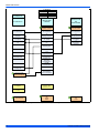
TABLE OF CONTENTS
GENERAL . . . . . . . . . . . . . . . . . . . . . . . . . . . . . . . . . . . . . . .
SAFETY . . . . . . . . . . . . . . . . . . . . . . . . . . . . . . . . . . . . . . . . .
UNIT INSTALLATION . . . . . . . . . . . . . . . . . . . . . . . . . . . . . .
EVACUATION . . . . . . . . . . . . . . . . . . . . . . . . . . . . . . . . . . . .
ELECTRICAL CONNECTIONS . . . . . . . . . . . . . . . . . . . . . . .
1
1
2
5
5
SYSTEM CHARGE . . . . . . . . . . . . . . . . . . . . . . . . . . . . . . .
INSTRUCTING THE OWNER . . . . . . . . . . . . . . . . . . . . . . .
AC CONTROL BOARD FUNCTIONALITY . . . . . . . . . . . . .
WIRING DIAGRAM . . . . . . . . . . . . . . . . . . . . . . . . . . . . . . .
11
11
12
16
LIST OF FIGURES
Typical Installation with Required Clearances . . . . . . . . . . . .
Tubing Hanger . . . . . . . . . . . . . . . . . . . . . . . . . . . . . . . . . . . .
Underground Installation . . . . . . . . . . . . . . . . . . . . . . . . . . . . .
Heat Protection . . . . . . . . . . . . . . . . . . . . . . . . . . . . . . . . . . . .
Typical Field Wiring . . . . . . . . . . . . . . . . . . . . . . . . . . . . . . . . .
Communications Harness Connection . . . . . . . . . . . . . . . . . .
CFM Selection Board . . . . . . . . . . . . . . . . . . . . . . . . . . . . . . .
Communicating AC with Communicating
Air Handler or Furnace . . . . . . . . . . . . . . . . . . . . . . . . . . . . . .
3
4
4
5
6
6
7
7
Communicating AC with Non-Communicating Air Handler
or Furnace using Communicating Interface Control . . . . . . . . 7
Thermostat Wiring – Single Stage Air Conditioner
(with AC control) – PSC Air Handler . . . . . . . . . . . . . . . . . . . . 8
Thermostat Wiring – Single Stage Air Conditioner
(with AC control) – VS Air Handler . . . . . . . . . . . . . . . . . . . . . 9
Thermostat Wiring – Single Stage Air Conditioner
(with AC control) – Modulating Furnace . . . . . . . . . . . . . . . . 10
Wiring Diagram (2 - 4 Ton) . . . . . . . . . . . . . . . . . . . . . . . . . . 16
Wiring Diagram (5 Ton) . . . . . . . . . . . . . . . . . . . . . . . . . . . . 17
LIST OF TABLES
R-410A Saturation Properties . . . . . . . . . . . . . . . . . . . . . . . .
TEST Input Functionality . . . . . . . . . . . . . . . . . . . . . . . . . . . .
Operational Mode Display . . . . . . . . . . . . . . . . . . . . . . . . . . .
Status Code Display . . . . . . . . . . . . . . . . . . . . . . . . . . . . . . .
12
13
13
13
SECTION I: GENERAL
The outdoor units are designed to be connected to a matching indoor
coil with sweat connect lines. Sweat connect units are factory charged
with refrigerant for the highest sales volume evaporator plus 15 feet of
field supplied lines.
Matching indoor coils are available with a thermal expansion valve or
an orifice liquid feed sized for the most common usage. The orifice size
and/or refrigerant charge may need to be changed for some system
combinations, elevation differences, or total line lengths. See tabular
data sheet provided in unit literature packet for charge requirements.
Refer to Application Data covering “General Piping Recommendations
and Refrigerant Line Length” (Part Number 247077).
Status Code Display . . . . . . . . . . . . . . . . . . . . . . . . . . . . . . .
Operational Fault Codes . . . . . . . . . . . . . . . . . . . . . . . . . . . .
Sensor or Switch Fault Codes . . . . . . . . . . . . . . . . . . . . . . .
Wiring Related Fault Codes . . . . . . . . . . . . . . . . . . . . . . . . .
13
14
14
14
SECTION II: SAFETY
This is a safety alert symbol. When you see this symbol on
labels or in manuals, be alert to the potential for personal
injury.
Understand and pay particular attention to the signal words DANGER,
WARNING, or CAUTION.
DANGER indicates an imminently hazardous situation, which, if not
avoided, will result in death or serious injury.
WARNING indicates a potentially hazardous situation, which, if not
avoided, could result in death or serious injury.
CAUTION indicates a potentially hazardous situation, which, if not
avoided may result in minor or moderate injury. It is also used to
alert against unsafe practices and hazards involving only property damage.
562156-UIM-A-0610
562156-UIM-A-0610
5. The unit should not be operated at outdoor temperatures below 65°
F without an approved low ambient operation accessory kit installed.
6. The maximum allowable line length for this product is 75 feet.
Improper installation may create a condition where the operation of
the product could cause personal injury or property damage.
Improper installation, adjustment, alteration, service, or maintenance can cause injury or property damage. Refer to this manual
for assistance or for additional information, consult a qualified contractor, installer, or service agency.
This product must be installed in strict compliance with the
enclosed installation instructions and any applicable local, state,
and national codes including, but not limited to building, electrical,
and mechanical codes.
SECTION III: UNIT INSTALLATION
LOCATION
Before starting the installation, select and check the suitability of the
location for both the indoor and outdoor unit. Observe all limitations and
clearance requirements.
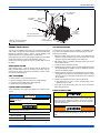
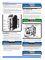
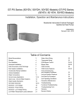
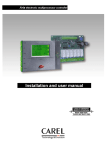
The outdoor unit must have sufficient clearance for air entrance to the
condenser coil, for air discharge, and for service access. See Figure 1
"Typical Installation with Required Clearances".
NOTICE
For multiple unit installations, units must be spaced a minimum of
24 inches apart (coil face to coil face).
R-410A systems operate at higher pressures than R-22 systems.
Do not use R-22 service equipment or components on R-410A
equipment. Service equipment Must Be Rated for R-410A.
INSPECTION
As soon as a unit is received, it should be inspected for possible damage during transit. If damage is evident, the extent of the damage
should be noted on the carrier’s delivery receipt. A separate request for
inspection by the carrier’s agent should be made in writing. See Local
Distributor for more information.
Requirements For Installing/Servicing R-410A Equipment
•
•
•
•
•
•
•
Gauge sets, hoses, refrigerant containers, and recovery systems
must be designed to handle the POE type oils and the higher
pressures of R-410A.
Manifold sets should be 800 PSIG high side and 250 PSIG low
side with 550 PSIG low side retard.
All hoses must have a 700 PSIG service pressure rating.
Leak detectors should be designed to detect HFC refrigerant.
Recovery equipment (including refrigerant recovery containers)
must be specifically designed to handle R-410A.
Do not use an R-22 TXV.
A liquid-line filter drier is required on every unit.
LIMITATIONS
The unit should be installed in accordance with all National, State, and
Local Safety Codes and the limitations listed below:
1. Limitations for the indoor unit, coil, and appropriate accessories
must also be observed.
2. Only variable speed air handlers or variable speed furnaces should
be used with these models.
3. The outdoor unit must not be installed with any duct work in the air
stream. The outdoor fan is the propeller type and is not designed to
operate against any additional external static pressure.
4. The maximum and minimum conditions for operation must be
observed to ensure a system that will give maximum performance
with minimum service.
2
If the unit is to be installed on a hot sun exposed roof or a black-topped
ground area, the unit should be raised sufficiently above the roof or
ground to avoid taking the accumulated layer of hot air into the outdoor
unit.
Provide an adequate structural support.
ADD-ON REPLACEMENT/RETROFIT
When this unit is being used as a replacement for an R-22 unit, it is
required that the outdoor unit, indoor coil, and metering device all be
replaced. Line-set change out is also recommended. The following
steps should be performed in order to insure proper system operation
and performance.
1. Change-out of the indoor coil to an approved R-410A coil with the
appropriate metering device.
2. Change-out of the line-set when replacing an R-22 unit with an
R-410A unit is highly recommended to reduce cross-contamination
of oils and refrigerants.
3. If change-out of the line set is not practical, then the following precautions should be taken.
•
Inspect the line set for kinks, sharp bends, or other restrictions,
and for corrosion.
• Determine if there are any low spots which might be serving as oil
traps.
• Flush the line set with a commercially available flush kit to
remove as much of the existing oil and contaminants as possible.
• Install a suction line filter-drier to trap any remaining contaminants, and remove after 50 hours of operation.
4. If the outdoor unit is being replaced due to a compressor burnout,
then installation of a 100% activated alumina suction-line filter drier
is required, in addition to the factory installed liquid-line drier. Operate the system for 10 hours. Monitor the suction drier pressure drop.
If the pressure drop exceeds 3 psig, replace both the suction-line
and liquid-line driers. After a total of 10 hours run time where the
suction-line pressure drop has not exceeded 3 psig, replace the liquid line drier, and remove the suction-line drier. Never leave a suction-line drier in the system longer than 50 hours of run time.
Johnson Controls Unitary Products
562156-UIM-A-0610
THERMOSTAT
NEC CLASS 1
WIRING
TO INDOOR
BLOWER
NEC CLASS 2
WIRING
60” OVERHEAD
CLEARANCE
WEATHERPROOF
DISCONNECT
SWITCH
TO COIL
24” SERVICE
ACCESS
CLEARANCE
SEAL OPENINGS WITH
PERMAGUM OR EQUIVALENT
10” COIL
CLEARANCE AREA
NOTE: ALL OUTDOOR WIRING
MUST BE WEATHERPROOF
FIGURE 1: Typical Installation with Required Clearances
GROUND INSTALLATION
TXV INSTALLATIONS
The unit may be installed at ground level on a solid base that will not
shift or settle, causing strain on the refrigerant lines and possible leaks.
Maintain the clearances shown in Figure 1 "Typical Installation with
Required Clearances" and install the unit in a level position.
The following are the basic steps for installation. For detailed instructions, refer to the Installation Instructions accompanying the TXV kit.
Install TXV kit as follows:
Normal operating sound levels may be objectionable if the unit is placed
directly under windows of certain rooms (bedrooms, study, etc.).
1. Relieve the holding charge from the indoor coil by depressing the
Schrader valve stem located in the end of the suction line. Cut the
spundown copper to allow installation of the suction line.
Isolate the unit from rain gutters to avoid any possible wash out of the
foundation.
2. After holding charge is completely discharged, loosen and remove
the schraeder cap seal.
ROOF INSTALLATION
3. Loosen and remove distributor cap seal.
When installing units on a roof, the structure must be capable of supporting the total weight of the unit, including a pad, lintel, rails, etc.,
which should be used to minimize the transmission of sound or vibration into the conditioned space.
UNIT PLACEMENT
1. Provide a base in the pre-determined location.
2. Remove the shipping carton and inspect for possible damage.
3. Compressor tie-down bolts should remain tightened.
4. Position the unit on the base provided.
5. Install the liquid line to the top of the thermal expansion valve with fitting supplied with the liquid line. Hand modify the liquid line to align
with casing opening. Hand tighten the liquid line and an additional
1/4 turn to seal.
6. Install the TXV equalizer line into the vapor line as follows:
a. Hand tighten the 1/4” SAE nut to the schraeder fitting and an
additional 1/3 turn to seal.
7. At this time do not attach sensing bulb. This will be covered later
after brazing of the lines.
LIQUID LINE FILTER-DRIER
The air conditioning unit’s copper spun filter/dryer is located on the liquid line.
NOTICE
Replacements for the liquid line drier must be exactly the same as
marked on the original factory drier. See Source 1 for O.E.M.
replacement driers.
Failure to do so or using a substitute drier or a granular type may
result in damage to the equipment.
Filter-Drier
Source 1 Part No.
Apply with Models
029-22195-000
All
Johnson Controls Unitary Products
4. Install the thermal expansion valve to the orifice distributor assembly
with supplied fittings. Hand tighten and turn an additional 1/4 turn to
seal. Do not overtighten fittings.
PIPING CONNECTIONS
This system uses R-410A refrigerant which operates at higher pressures than R-22. No other refrigerant may be used in this system.
Gauge sets, hoses, refrigerant containers, and recovery systems
must be designed to handle R-410A. If you are unsure, consult the
equipment manufacturer.
Never install a suction-line filter drier in the liquid line of an R-410A
system. Failure to follow this warning can cause a fire, injury or
death.
3
562156-UIM-A-0610
The outdoor condensing unit must be connected to the indoor evaporator coil using field supplied refrigerant grade copper tubing that is internally clean and dry. Units should be installed only with the tubing sizes
for approved system combinations as specified in tabular data sheet.
The charge given is applicable for total tubing lengths up to 15 feet. See
Application Data Part Number 247077 for installing tubing of longer
lengths and elevation differences.
TO INDOOR
COIL
LIQUID
LINE
TO OUTDOOR
COIL
INSULATED
VAPOR LINE
CAP
PVC
CONDUIT
NOTICE
Using a larger than specified line size could result in oil return problems. Using too small a line will result in loss of capacity and other
problems caused by insufficient refrigerant flow. Slope horizontal
vapor lines at least 1" every 20 feet toward the outdoor unit to facilitate proper oil return.
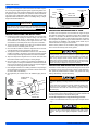
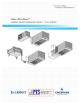
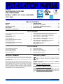
FIGURE 3: Underground Installation
PRECAUTIONS DURING BRAZING OF LINES
1. Install the lines with as few bends as possible. Care must be taken
not to damage the couplings or kink the tubing. Use clean hard
drawn copper tubing where no appreciable amount of bending
around obstruction is necessary. If soft copper must be used, care
must be taken to avoid sharp bends which may cause a restriction.
All outdoor unit and evaporator coil connections are copper-to-copper
and should be brazed with a phosphorous-copper alloy material such
as Silfos-5 or equivalent. DO NOT use soft solder. The outdoor units
have reusable service valves on both the liquid and vapor connections.
The total system refrigerant charge is retained within the outdoor unit
during shipping and installation. The reusable service valves are provided to evacuate and charge per this instruction.
2. The lines should be installed so that they will not obstruct service
access to the coil, air handling system, or filter.
Serious service problems can be avoided by taking adequate precautions to ensure an internally clean and dry system.
PRECAUTIONS DURING LINE INSTALLATION
3. Care must also be taken to isolate the refrigerant lines to minimize
noise transmission from the equipment to the structure.
4. The vapor line must be insulated with a minimum of 1/2" foam rubber
insulation (Armaflex or equivalent). Liquid lines that will be exposed
to direct sunlight and/or high temperatures must also be insulated.
5. Tape and suspend the refrigerant lines as shown. DO NOT allow
tube metal-to-metal contact. See Figure 2 "Tubing Hanger".
6. Use PVC piping as a conduit for all underground installations as
shown in Figure 3 "Underground Installation". Buried lines should be
kept as short as possible to minimize the build up of liquid refrigerant
in the vapor line during long periods of shutdown
7. Pack fiberglass insulation and a sealing material such as permagum
around refrigerant lines where they penetrate a wall to reduce vibration and to retain some flexibility.
8. See application part number 247077 for additional piping information.
SHEET METAL
HANGER
INCORRECT
TAPE
FIGURE 2: Tubing Hanger
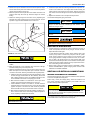
PRECAUTIONS DURING BRAZING SERVICE VALVE
Precautions should be taken to prevent heat damage to service valves
by wrapping a wet rag around it as shown in Figure 4 "Heat Protection".
Also, protect all painted surfaces, insulation, and plastic base during
brazing. After brazing, cool joint with wet rag.
This is not a backseating valve. The service access port has a
valve core. Opening or closing valve does not close service access
port.
If the valve stem is backed out past the chamfered retaining wall,
the O-ring can be damaged causing leakage or system pressure
could force the valve stem out of the valve body possibly causing
personal injury.
LIQUID
LINE
CORRECT
Dry nitrogen should always be supplied through the tubing while it
is being brazed, because the temperature is high enough to cause
oxidation of the copper unless an inert atmosphere is provided. The
flow of dry nitrogen should continue until the joint has cooled.
Always use a pressure regulator and safety valve to insure that only
low pressure dry nitrogen is introduced into the tubing. Only a small
flow is necessary to displace air and prevent oxidation.
INSULATED
VAPOR LINE
The valve can be opened by removing the plunger cap and fully inserting a hex wrench into the stem and backing out counter-clockwise until
valve stem just touches the chamfered retaining wall.
Connect the refrigerant lines using the following procedure:
1. Refer to the Tabular Data Sheet for proper vapor and liquid line sizing.
Do not leave the system open to the atmosphere. Unit damage
could occur due to moisture being absorbed by the POE oil in the
system. This type of oil is highly susceptible to moisture absorption.
4
Johnson Controls Unitary Products
562156-UIM-A-0610
2. Remove the cap and Schrader core from both the liquid and vapor
service valve service ports at the outdoor unit. Connect low pressure
nitrogen to the liquid line service port.
3. Braze the liquid line to the liquid valve at the outdoor unit. Be sure to
wrap the valve body with a wet rag. Allow the nitrogen to continue
flowing.
4. Relieve the holding charge from the indoor coil by depressing the
Schrader valve stem located in the end of the suction line. Cut the
spundown copper to allow installation of the suction line.
8. Protect the vapor valve with a wet rag and braze the vapor line connection to the outdoor unit. The nitrogen flow should be exiting the
system from the vapor service port connection. After this connection
has cooled, remove the nitrogen source from the liquid fitting service
port.
9. Replace the Schrader core in the liquid and vapor valves.
10.Leak test all refrigerant piping connections.
NOTICE
Line set and indoor coil can be pressurized to 250 psig with dry
nitrogen and leak tested with a bubble type leak detector. Then
release the nitrogen charge.
NOTICE
Do not use the system refrigerant in the outdoor unit to purge or
leak test.
Never attempt to repair any brazed connections while the system is
under pressure. Personal injury could result.
SECTION IV: EVACUATION
1. It will be necessary to evacuate the system to 500 microns or less. If
a leak is suspected, leak test with dry nitrogen to locate the leak.
Repair the leak and test again.
FIGURE 4: Heat Protection
The evaporator is pressurized.
5. If TXV has not been installed refer to Page 3 “TXV INSTALLATIONS”.
6. Braze the liquid line to the evaporator liquid connection. Nitrogen
should be flowing through the evaporator coil.
7. Slide the grommet away from the vapor connection at the indoor coil.
Braze the vapor line to the evaporator vapor connection. After the
connection has cooled, slide the grommet back into original position.
a. Install the TXV bulb to the vapor line near the equalizer line, using
the bulb clamp(s) furnished with the TXV assembly. Ensure the
bulb is making maximum contact. For detailed instructions, refer
to the Installation Instructions accompanying the TXV kit.
b. Bulb should be installed on a horizontal run of the vapor line if
possible. The bulb should be installed on top of the line.
c. If bulb installation is made on a vertical run, the bulb should be
located at least 16 inches from any bend, and on the tubing sides
opposite the plane of the bend. The bulb should be positioned
with the bulb tail at the top, so that the bulb acts as a reservoir.
d. Bulb should be insulated using thermal insulation provided to protect it from the effect of the surrounding ambient temperature.
Cover completely to insulate from air-stream.
To verify that the system has no leaks, simply close the valve to the
vacuum pump suction to isolate the pump and hold the system
under vacuum. Watch the micron gauge for a few minutes. If the
micron gauge indicates a steady and continuous rise, it’s an indication of a leak. If the gauge shows a rise, then levels off after a few
minutes and remains fairly constant, it’s an indication that the system
is leak free but still contains moisture and may require further evacuation if the reading is above 500 microns.
2. While system is being evacuated proceed to SECTION V ”ELECTRICAL CONNECTIONS”. System charging will be covered under
SECTION VI ”SYSTEM CHARGE”
SECTION V: ELECTRICAL CONNECTIONS
GENERAL INFORMATION & GROUNDING
Check the electrical supply to be sure that it meets the values specified
on the unit nameplate and wiring label.
Power wiring, control (low voltage) wiring, disconnect switches, and
over current protection must be supplied by the installer. Wire size
should be sized per NEC requirements.
All field wiring must USE COPPER CONDUCTORS ONLY and be
in accordance with Local, National, Fire, Safety, & Electrical Codes.
This unit must be grounded with a separate ground wire in accordance with the above codes.
The complete connection diagram and schematic wiring label is located
on the inside surface of the unit service access panel.
In all cases, mount the TXV bulb after vapor line is brazed and has
had sufficient time to cool.
Johnson Controls Unitary Products
5
562156-UIM-A-0610
FIELD CONNECTIONS POWER WIRING
1. Install the proper size weatherproof disconnect switch outdoors and
within sight of the unit.
2. Remove the screws at the bottom of the corner cover. Slide corner
cover down and remove from unit. See Figure 5 "Typical Field Wiring".
3. Run power wiring from the disconnect switch to the unit.
4. Remove the service access panel to gain access to the unit wiring.
Route wires from disconnect through power wiring opening provided
and into the unit control box.
5. Install the proper size time-delay fuses or circuit breaker, and make
the power supply connections.
Corner
Cover
Service
Access
Panel
NOTICE
To eliminate erratic operation, seal the hole in the wall at the thermostat with permagum or equivalent to prevent air drafts affecting
the operation of the thermostat.
FIELD CONNECTIONS CONTROL WIRING
(SERIAL COMMUNICATION)
1. The Communications Harness is provided with the Touch Screen
Communicating Control.
2. Route low voltage four conductor shielded thermostat communications harness into junction box and connect to communications port
on control board. See Figure 6 "Communications Harness Connection".
3. Route low voltage wiring into bottom of control box. Make low voltage wiring connections inside the junction box per Figures 8-9.
4. The complete connection diagram and schematic wiring label is
located on the inside surface of the unit service access panel.
If unit is going to be setup as a communicating system, the conventional wiring must be removed from the Outdoor Control Board, if
not, damage to control board or indoor control could occur.
Control
Wiring
COMMUNICATIONS PORT
CONTROL BOARD
COMMUNICATIONS
HARNESS
Power
Wiring
Ambient
Temperature
Sensor
FIGURE 5: Typical Field Wiring
FIELD CONNECTIONS CONTROL WIRING
(CONVENTIONAL)
1. Route low voltage wiring into bottom of control box. Make low voltage wiring connections inside the junction box per Figures 10-12
“Thermostat Wiring”.
JUNCTION
BOX
2. The complete connection diagram and schematic wiring label is
located on the inside surface of the unit service access panel.
3. Replace the corner cover and service access panel that were
removed in Steps 2 and 4 of the ”FIELD CONNECTIONS POWER
WIRING” section.
NOTICE
Ambient temperature sensor should extend below corner cover by
1”.
4. All field wiring to be in accordance with national electrical codes
(NEC) and/or local-city codes.
5. Mount the thermostat about 5 ft. above the floor, where it will be
exposed to normal room air circulation. Do not place it on an outside
wall or where it is exposed to the radiant effect from exposed glass
or appliances, drafts from outside doors, or supply air grilles.
6. Route the 24-volt control wiring (NEC Class 2) from the outdoor unit
to the indoor unit and thermostat.
FIGURE 6: Communications Harness Connection
5. Replace the corner cover and service access panel that were
removed in Steps 2 and 4 of the “Field Connections Power Wiring”
section.
NOTICE
Ambient temperature sensor should extend below corner cover by
1”.
6. Mount the thermostat about 5 ft. above the floor, where it will be
exposed to normal room air circulation. Do not place it on an outside
wall or where it is exposed to the radiant effect from exposed glass
or appliances, drafts from outside doors, or supply air grilles.
7. Route the 24-volt control wiring (NEC Class 2) from the outdoor unit
to the indoor unit and thermostat.
NOTICE
To eliminate erratic operation, seal the hole in the wall at the thermostat with Pergamum or equivalent to prevent air drafts affecting
the operation of the thermostat.
6
Johnson Controls Unitary Products
562156-UIM-A-0610
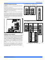
CFM SELECTION BOARD SETTINGS
For proper system operation the CFM Selection Board jumpers must be
set properly.
Refer to the Tech Guide for the recommended air flow settings for each
size condensing unit and matchup.
Set the cooling speed per the instructions for the air handler or furnace
by selecting the correct COOL and ADJ taps. Verify the airflow using
the LED display on the CFM selection board.
The HUMIDISTAT jumper must also be removed if a dehumidistat is
installed.
If a dehumidification control is installed, it is recommended that a minimum air flow of 325 cfm/ton be supplied at all times.
Touch Screen
Communicating
Control
Air Handler/Furnace
Communicating
Control
Air Conditioner
Communicating
Control
A+
A+
A+
R
R
R
GND
or C
GND
or C
GND
or C
B-
B-
B-
If installed as a communicating system (outdoor, indoor and thermostat), the system will automatically adjust to the optimal airflow settings.
These parameters can also be modified using the Touch Screen Communicating Control. Refer to the Touch Screen Communicating Control
owner’s manual for this procedure. Manual setting of the airflow jumpers on the ID equipment is not necessary with the Touch Screen Communicating Control.
R
C
Y1
HEAT
A
B
C
D
DELAY
COOL ADJUST
A
B
C
D
LED 2
Y2
FIGURE 8: Communicating AC with Communicating Air Handler or
Furnace
Touch Screen
Communicating
Control
Communicating
Indoor
Interface Control
Non-Communicating
Indoor Unit
Air Conditioner
Communicating
Control
A+
A+
A+
R
R
R
GND
or C
GND
or C
GND
or C
B-
B-
BR
FIGURE 7: CFM Selection Board
DEHUMIDIFICATION CONTROL
A dehumidification control accessory 2HU06700124 may be used with
variable speed air handlers or furnaces in high humidity areas. This
control works with the variable speed indoor unit to provide cooling at a
reduced air flow, lowering evaporator temperature and increasing latent
capacity. The humidistat in this control opens the humidistat contacts on
humidity rise. To install, refer to instructions packaged with the accessory and Figures 7-9. Prior to the installation of the dehumidification
control, the jumper across the HUMIDISTAT terminals on the indoor
variable speed air handler or furnace CFM selection board must be
removed.
During cooling, if the relative humidity in the space is higher than the
desired set point of the dehumidification control, the variable speed
blower motor will operate at lower speed until the dehumidification control is satisfied. A 40-60% relative humidity level is recommended to
achieve optimum comfort.
Johnson Controls Unitary Products
G
G
C
O
O
Y1
Y
Y2
Y
Y2
C
R
W
W2
Wire per
non-comm.
installation
manual
Assume that
connections
are from
thermostat
Y2
C
R
W
W2
DHUM
DHUM
HUM
HUM
FIGURE 9: Communicating AC with Non-Communicating Air Handler
or Furnace using Communicating Interface Control
7
562156-UIM-A-0610
For additional connection diagrams for all UPG equipment refer to “Low Voltage System Wiring” document available online at www.upgnet.com in the
Product Catalog Section.
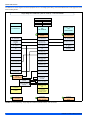
6LQJOH6WDJH$LU&RQGLWLRQHUZLWK$&FRQWURO ± 36&$LU+DQGOHU
,'02'(/6
$+3
$+;
0$
0;
7+(50267$7
6,1*/(67$*(
$,5
&21',7,21(5
36&
$,5+$1'/(5
67+683E
36&
$,5+$1'/(5
&21752/
6,1*/(67$*(
$,5&21',7,21(5
&
± 9ROW&RPPRQ
&20
± 9ROW&RPPRQ
&
± 9ROW&RPPRQ
<
)LUVW6WDJH
&RPSUHVVRU
<<
6HFRQGRU)XOO
6WDJH&RPSUHVVRU
<
)LUVW6WDJH&RPSUHVVRU
5
± 9ROW+RW
5
± 9ROW+RW
5
± 9ROW+RW
*
)DQ
*
)DQ
<
6HFRQG6WDJH
&RPSUHVVRU
:
)LUVW6WDJH+HDW
:
6HFRQG6WDJH+HDW
<
)LUVW
6WDJH&RPSUHVVRU
2
5HYHUVLQJ9DOYH
(QHUJL]HGLQ&RRO
:
6HFRQG6WDJH+HDW
;/
0DOIXQFWLRQ/LJKW
+80
+XPLGLW\6ZLWFK
2SHQRQ+XPLGLW\5LVH
:2%
)LUVW6WDJH+HDW
([WHUQDO+XPLGLVWDW
2SWLRQDO
2SHQRQ+XPLGLW\5LVH
+80287
9$&RXW
+XPLGLILHU
($&
9$&RXW
(OHFWURQLF$LU&OHDQHU
9$&+XPLGLILHU
2SWLRQDO
9$&
(OHFWURQLF$LU&OHDQHU
2SWLRQDO
0RYH+8067$7
MXPSHUWR³<(6´
LIKXPLGLVWDWLVWREH
XVHG
5HIHUWR$+
GRFXPHQWDWLRQ
IRU:DQG:HOHFWULF
KHDWVWDJLQJRSWLRQV
-XPSHUPXVWEHVHW
WR³*$6(/(&´
-XPSHUPXVWEHVHW
WR³(/(&´
3DUW1XPEHU
6+8
3DUW1XPEHUV
6$3 /HJDF\
3DUW1XPEHU
6$3
FIGURE 10: Thermostat Wiring – Single Stage Air Conditioner (with AC control) – PSC Air Handler
8
Johnson Controls Unitary Products
562156-UIM-A-0610
,'02'(/6
$9
09
7+(50267$7
9$5,$%/(
63(('
$,5+$1'/(5
67+683E
9$5,$%/(63(('
$,5+$1'/(5
&21752/
6,1*/(67$*(
$,5
&21',7,21(5
6,1*/(67$*(
$,5&21',7,21(5
&
± 9ROW&RPPRQ
&20
± 9ROW&RPPRQ
&
± 9ROW&RPPRQ
<
)LUVW6WDJH
&RPSUHVVRU
<<
6HFRQGRU)XOO
6WDJH&RPSUHVVRU
<
)LUVW6WDJH&RPSUHVVRU
5
± 9ROW+RW
5
± 9ROW+RW
5
± 9ROW+RW
*
)DQ
*
)DQ
<
6HFRQG6WDJH
&RPSUHVVRU
:
)LUVW6WDJH+HDW
:
6HFRQG6WDJH+HDW
<
)LUVW
6WDJH&RPSUHVVRU
2
5HYHUVLQJ9DOYH
(QHUJL]HGLQ&RRO
:
6HFRQG6WDJH+HDW
;/
0DOIXQFWLRQ/LJKW
+80
+XPLGLW\6ZLWFK
2SHQRQ+XPLGLW\5LVH
:2%
)LUVW6WDJH+HDW
([WHUQDO+XPLGLVWDW
2SWLRQDO
2SHQRQ+XPLGLW\5LVH
+80287
9$&RXW
+XPLGLILHU
($&
9$&RXW
(OHFWURQLF$LU&OHDQHU
9$&+XPLGLILHU
2SWLRQDO
9$&
(OHFWURQLF$LU&OHDQHU
2SWLRQDO
0RYHWKH+8067$7
MXPSHUWR³<(6´
LIKXPLGLVWDWLVWREH
XVHG
5HIHUWR$+
GRFXPHQWDWLRQ
IRU:DQG:HOHFWULF
KHDWVWDJLQJRSWLRQV
-XPSHUPXVWEHVHW
WR³*$6(/(&´
-XPSHUPXVWEHVHW
WR³(/(&´
3DUW1XPEHU
6+8
3DUW1XPEHU
6$3
3DUW1XPEHU
6$3
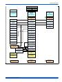
FIGURE 11: Thermostat Wiring – Single Stage Air Conditioner (with AC control) – VS Air Handler
Johnson Controls Unitary Products
9
562156-UIM-A-0610
,'02'(/6
7+(50267$7
</&&
7&
<0/0
<00
7/&
700
</&/&
6,1*/(67$*(
$,5
&21',7,21(5
02'8/$7,1*
)851$&(
67+683E
02'8/$7,1*
)851$&(&21752/
6,1*/(67$*(
$,5&21',7,21(5
&
± 9ROW&RPPRQ
&
± 9ROW&RPPRQ
&
± 9ROW&RPPRQ
<
)LUVW6WDJH
&RPSUHVVRU
<
)LUVW6WDJH&RPSUHVVRU
<
)LUVW6WDJH&RPSUHVVRU
5
± 9ROW+RW
5
± 9ROW+RW
5
± 9ROW+RW
*
)DQ
*
)DQ
<
6HFRQG6WDJH
&RPSUHVVRU
:
0RGXODWLQJ+HDW
<<
6HFRQGRU)XOO
6WDJH&RPSUHVVRU
2
5HYHUVLQJ9DOYH
(QHUJL]HGLQ&RRO
/2&203
6LQJOH6WDJH
&RPSUHVVRU287
+,&203
6HFRQG6WDJH
&RPSUHVVRU287
:
6HFRQG6WDJH+HDW
:2%
)LUVW6WDJH+HDW
'+80
'HKXPLGLILFDWLRQ
2SHQRQ+XPLGLW\5LVH
([WHUQDO+XPLGLVWDW
2SWLRQDO
2SHQRQ+XPLGLW\5LVH
0RYH+80,',67$7
MXPSHUWR³<(6´
LIKXPLGLVWDWLVWREHXVHG
-XPSHUPXVWEHVHW
WR³*$6(/(&´
-XPSHUPXVWEHVHW
WR³*$6´
3DUW1XPEHU
6+8
3DUW1XPEHU¶V
6$3
3DUW1XPEHU
6$3
FIGURE 12: Thermostat Wiring – Single Stage Air Conditioner (with AC control) – Modulating Furnace
10
Johnson Controls Unitary Products
562156-UIM-A-0610
SECTION VI: SYSTEM CHARGE
Refrigerant charging should only be carried out by a qualified air
conditioning contractor.
Subcooling Charging Method
This condensing unit must only be used with the matching thermostatic
expansion valve kit listed in the Tabular Data Sheet. This unit must be
charged during cooling operation (Y1) operation only. Charging
should be matched per the subcooling chart located on the rating plate.
1. Set the system running in the cooling (Y1) cooling mode by setting
the thermostat at least 6°F below the room temperature.
2. Operate the system for a minimum of 15-20 minutes.
R-410A refrigerant cylinders are rose colored, and have a dip tube
which allows liquid to flow out of the cylinder in the Upright Position. Always charge the system slowly with the tank in the upright
position.
3. Refer to the Tech Guide for the recommended airflow and verify this
indoor airflow (it should be about 400 SCFM per ton).
4. Measure the liquid refrigerant pressure P and temperature T at the
service valve.
5. Calculate the saturated liquid temperature ST from Table 1 "R-410A
Saturation Properties".
6. Subcooling temperature TC = Saturated Temperature (ST) - Liquid
Temp (T).
DO NOT attempt to pump “Total System Charge” into outdoor unit
for maintenance, service, etc. This may cause damage to the compressor and/or other components. the outdoor unit only has enough
volume for the factory charge, not the “Total System Charge”.
1. The factory charge in the outdoor unit includes enough charge for
the unit, a 15 ft. line set and the smallest rated indoor coil match-up.
Some indoor coil matches may require additional charge. See tabular data sheet provided in unit literature packet for charge requirements.
Example: The pressure P and temperature T measured at the liquid
service port is 360 Psig and 93°F. From Table 1, the saturated temperature for 360 Psig is 109°. The subcooling temperature TC =
109°-93°=16°F
Add charge if the calculated subcooling temperature TC in Step 6 is
lower than the recommended level. Remove and recover the refrigerant
if the subcooling TC is higher than the recommended level. See Table 1
for R-410A saturation temperatures.
2. Once line size/length and indoor coil adders have been figured,
weigh in this amount of charge by adding it through the liquid service
port while the indoor side of the system is still under a vacuum. The
vacuum that is on the indoor side of the system will allow you to add
most of the charge adder. If you are not able to add the full amount
then add the remainder after starting up the system to verify proper
subcooling. The subcooling charging method is explained further in
this section.
After disconnecting manifold gauge set check flare caps on service
ports to be sure they are leak tight. DO NOT OVERTIGHTEN (between
40 and 60 inch - lbs. maximum).
3. Release the refrigerant charge from the outdoor unit into the system.
Open both the liquid and vapor service valves at outdoor unit by
removing the plunger cap and with an allen wrench back out counter-clockwise until valve stem just touches the chamfered retaining
wall. ”PRECAUTIONS DURING BRAZING SERVICE VALVE”.
2. Determine indoor coil adjustment from tabular data sheet.
4. Replace plunger cap finger tight, then tighten an additional 1/12 turn
(1/2 hex flat). Cap must be replaced to prevent leaks.
5. Use the following subcooling charging method whenever additional
refrigerant is required for the system charge. A superheat charging
method is not suitable for TXV equipped systems.
Measurement Method
If a calibrated charging cylinder or accurate weighing device is available, add refrigerant accordingly.
The “Total System Charge” must be permanently stamped on the unit
data plate.
Total system charge is determined as follows:
1. Determine outdoor unit charge from tabular data sheet.
3. Calculate the line charge using the tabular data sheet if line length is
greater than 15 feet.
4. Total system charge = item 1 + item 2 + item 3.
5. Permanently stamp the unit data plate with the total amount of refrigerant in the system.
SECTION VII: INSTRUCTING THE OWNER
Assist owner with processing warranty cards and/or online registration.
Review Owners Manual, provide a copy to the owner, and provide guidance on proper operation and maintenance. Instruct the owner or the
operator how to start, stop, and adjust temperature setting.
The installer should also instruct the owner on proper operation and
maintenance of all other system components.
MAINTENANCE
Compressor damage will occur if system is improperly charged. On
new system installations, charge system per tabular data sheet for
the matched coil and follow guidelines in this instruction.
1. Dirt should not be allowed to accumulate on the outdoor coils or
other parts in the air circuit. Clean as often as necessary to keep
the unit clean. Use a brush, vacuum cleaner attachment, or other
suitable means.
2. The outdoor fan motor is permanently lubricated and does not
require periodic oiling.
Johnson Controls Unitary Products
11
562156-UIM-A-0610
5. The indoor coil and drain pan should be inspected and cleaned regularly to prevent odors and assure proper drainage.
NOTICE
On 5 Ton unit the outdoor fan motor is a permanent magnet DC
brushless type. The motor requires a separate Electronic Control to
operate. Do not attempt to replace this motor with a typical PSC
type. Damage to Electronic Control may result.
3. If the coil needs to be cleaned, use clean water to wash dust, dirt,
and debris from outdoor condensing coil.
NOTICE
DO NOT use coil cleaners to clean outdoor condensing coil. cleaners containing HF-, hydroxides, chlorides, and sulfates can greatly
reduce the lifetime of the aluminum condensing coil.
4. Refer to the furnace or air handler instructions for filter and blower
motor maintenance.
Do not connect manifold gauges unless trouble is suspected.
Approximately 3/4 ounce of refrigerant will be lost each time a standard manifold gauge is connected.
IT IS UNLAWFUL TO KNOWINGLY VENT, RELEASE OR DISCHARGE REFRIGERANT INTO THE OPEN AIR DURING
REPAIR, SERVICE, MAINTENANCE OR THE FINAL DISPOSAL
OF THIS UNIT.
WHEN THE SYSTEM IS FUNCTIONING PROPERLY AND THE
OWNER HAS BEEN FULLY INSTRUCTED, SECURE THE
OWNER’S APPROVAL.
TABLE 1: R-410A Saturation Properties
TEMP. °F
PRESSURE
PSIG
TEMP. °F
PRESSURE
PSIG
TEMP. °F
PRESSURE
PSIG
TEMP. °F
PRESSURE
PSIG
TEMP. °F
PRESSURE
PSIG
45
129.70
60
169.60
75
217.40
90
274.10
105
340.50
46
132.20
61
172.60
76
220.90
91
278.20
106
345.30
47
134.60
62
175.50
77
224.40
92
282.30
107
350.10
48
137.10
63
178.50
78
228.00
93
286.50
108
355.00
49
139.60
64
181.60
79
231.60
94
290.80
109
360.00
50
142.20
65
184.60
80
235.30
95
295.10
110
365.00
51
144.80
66
187.70
81
239.00
96
299.40
111
370.00
52
147.40
67
190.90
82
242.70
97
303.80
112
375.10
53
150.10
68
194.10
83
246.50
98
308.20
113
380.20
54
152.80
69
197.30
84
250.30
99
312.70
114
385.40
55
155.50
70
200.60
85
254.10
100
317.20
115
390.70
56
158.20
71
203.90
86
258.00
101
321.80
116
396.00
57
161.00
72
207.20
87
262.00
102
326.40
117
401.30
58
163.90
73
210.60
88
266.00
103
331.00
118
406.70
59
166.70
74
214.00
89
270.00
104
335.70
119
412.20
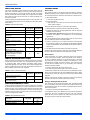
SECTION VIII: AC CONTROL BOARD
FUNCTIONALITY
ANIT-SHORT CYCLE DELAY
The control includes a five-minute anti-short cycle delay (ASCD) timer
to prevent the compressor from short cycling after a power interruption
or thermostat signal interruption. The ASCD timer is applied when the
control is first powered from the indoor unit thermostat and immediately
following the completion of a compressor run cycle. The compressor
and the outdoor fan will not operate during the five minutes that the
timer is active.
The ASCD timer can be bypassed by connecting the TEST terminals
for three seconds while the thermostat is calling for compressor operation (Y1 input signal energized).
12
LOW VOLTAGE DETECTION
The control monitors the transformer secondary (24 VAC) voltage and
provides low voltage protection for the AC unit and its components. In
particular, the control prevents contactor chatter during low voltage conditions. If the voltage drops below approximately 19 VAC, the control
will continue to energize any relays that are already energized but will
not energize any additional relays until the voltage level increases. If
the voltage drops below approximately 16 VAC, the control will immediately de-energize the relay outputs and will not energize any relays until
the voltage level increases. The control will store and display the appropriate fault codes when low voltage conditions occur.
TEST INPUT
The control includes a TEST input connector that can be used for various testing functions during installation and service. Table 2 summarizes the behavior of the control when the two TEST pins are
connected.
Johnson Controls Unitary Products
562156-UIM-A-0610
TABLE 2: TEST Input Functionality
Duration of
connection (seconds)
Control Behavior with no system
master signals present
Control behavior with system
master signals present
<2
No response
No response
Display compressor type TS, Ultratech, or
single stage compressor, Ignore LPS
Bypass ASCD (Reduce timer to zero immediately).
If Y1 (thermostat or communication) is present and the
high-pressure switch is closed, contactors will be energized.
Clear soft lockout
Clear soft lockout
Clear hard lockout
Clear hard lockout
Reset TS anticipation mode counter
to zero for TS systems.
Reset TS anticipation mode counter
to zero for TS systems.
2<
Reduce TS staging delays for TS
systems as described below.
Connection removed
Resume normal LED display
Connection not removed
Nothing more than previously explained
LED DIAGNOSTIC INDICATORS
OPERATIONAL MODE DISPLAY
The control includes two LED’s that display diagnostic information.
LED1 is red and LED2 is green. These LED’s are used to display operational mode, fault information. A third LED, LED3 is used to display
status information. LED3 is yellow. These LED’s are used to display
operational mode, status, and fault information.
The control will display its active operational mode using the onboard
LED’s when the TEST pins are connected while no thermostat signals
are energized. Table 3 "Operational Mode Display" describes the operational modes. The control will display the operational mode as long as
the TEST pins are shorted and no thermostat signals are energized.
When the TEST pin short is removed, the control will return to normal
LED displays.
OPERATIONAL MODE DETECTION
The control can be used in a variety of applications including AC units
with multistage compressors. The control uses various inputs to determine the proper mode of operation.
The control senses the connections that are made to M, M1, and M2
terminals and determines the correct operational mode for the control.
This is done each time power to the control is cycled. Therefore, it is
important that no loads be attached to the M1 or M2 terminals of the
control for single-stage compressors, and no loads be attached to the
M1 terminal of the control for a scroll two-stage compressor.
TABLE 3: Operational Mode Display
Compressor Type
LED1 (Red)
LED2 (Green)
1 flash
---
TS Compressor
2 flashes
---
UltraTech Compressor
3 flashes
---
Single Stage Compressor
STATUS CODE DISPLAY
The control also provides status codes using the LED’s. Status codes
indicate the state of the operation of the unit but do not represent a
fault. Tables 4 & 5 describes the LED displays during status codes. Status codes will not be displayed when a fault code is present.
Do not connect any loads to the M1 or M2 terminals of the control
for single-stage compressors, and no loads should be attached to
the M1 terminal of the control for scroll two-stage compressor.
Incorrect system behavior could result.
TABLE 4: Status Code Display
Description
Required Condition
LED1 (Red)
LED2 (Green)
No power to control
No power to control
OFF
OFF
First-stage compressor operation – TS or UltraTech
TS – M & M1 energized,
UltraTech – M energized,
Single Stage - NA
OFF
ON
Second-stage compressor operation - TS, UltraTech, or
Single Stage
TS and UltraTech – M & M2 energized,
Single Stage – M energized
ON
ON
Control normal operation – no communication or call for
compressor present
No faults active, Y1 or Y2 not present
OFF
2s ON / 2s OFF
Control normal operation – in ASCD period
No faults active, Y1 or Y2 present,
ASCD timer not expired
OFF
0.1 sec ON /
0.1 sec OFF
TABLE 5: Status Code Display
Description
Required Condition
Control normal operation – with active communication present
System is active and presently communicating successfully.
Control powered – without active communication present
System has 24 VAC present and the microprocessor is active.
Johnson Controls Unitary Products
LED3 (Yellow)
0.1 sec ON /
0.1 sec OFF
2s ON / 2s OFF
13
562156-UIM-A-0610
FAULT CODE DISPLAY
LOCKOUT MODES
The control will display any fault code that is currently active using the
LED’s. The control will display the fault code, pause two seconds, and
display the fault again. The control will continue the fault code display
until the condition that caused the fault code no longer exists. If multiple
fault codes are present at the same time, the control will display only
the most recent fault.
Soft Lockout
Table 6 describes the operational faults that the control can detect. The
control displays these types of errors by flashing the LED1 (Red) and/or
LED2 (Green).
TABLE 6: Operational Fault Codes
The control will cause a soft lockout during the following conditions.
Detailed descriptions of the conditions required for the control to enter
the soft lockout mode are contained in other sections of this document.
1. High-pressure switch
a. Two openings within six hours
2. Low-pressure switch
a. One opening of the switch for more than five seconds except
under certain conditions.
During the soft lockout mode, the control will do the following.
LED1 Flash
Code (Red)
LED2 Flash
Code (Green)
ON
OFF
2. Energize the LED’s with the appropriate flash codes as described
elsewhere in this document.
High-pressure switch fault (not in
lockout yet)
1
OFF
System in high-pressure switch
lockout
3. In communication applications the fault code will be stored in the
thermostat. (This feature is not available for non communicating
applications).
2
OFF
System in low-pressure switch
lockout
The control will reset the soft lockout condition when any of the following occur following removal of the fault condition.
4
OFF
Low Voltage (<19.2VAC) preventing
further relay outputs
5
OFF
Low Voltage (<16 VAC) stopped
current relay outputs
1. Power is cycled to the R or Y1 inputs of the control. This will cause
the soft lockout condition to be reset when the thermostat is satisfied
or when the thermostat is set to SYSTEM OFF and back to HEAT or
COOL mode.
6
OFF
Description
Control Failure
Operational Faults
9
ON
SENSOR OR SWITCH FAULT CODES
Table 7 describes the faults that the control can detect when a problem
is present with a sensor or switch. The control displays this type of error
by energizing LED1 (Red) constantly and flashing LED2 (Green).
These faults typically occur when an AC unit has been operating and a
problem occurs with a sensor or its wiring. These faults could also occur
during installation as the AC unit is configured.
TABLE 7: Sensor or Switch Fault Codes
LED1 Flash
Code (Red)
LED2 Flash
Code (Green)
Outdoor ambient temperature
sensor failure (short)
ON
1
Outdoor ambient temperature
sensor failure (open)
ON
2
Table 8 describes the faults that the control can detect when a problem
is present with the system wiring or jumper configurations. The control
displays this type of error by flashing LED1 (Red) and energizing LED2
(Green) constantly. These faults typically occur when the AC unit is first
installed or when a system component such as the room thermostat or
indoor unit is replaced or rewired.
TABLE 8: Wiring Related Fault Codes
LED1 Flash
Code (Red)
LED2 Flash
Code (Green)
Compressor contactor miswire
1
ON
Y2 present without Y1
2
ON
14
Hard Lockout
If four soft lockouts occur within a twelve-hour period, the control will
cause a hard lockout condition. These soft lockouts can be caused by
the same or different conditions. The control will function in the same
way during soft and hard lockout conditions. The difference is in the
requirements for resetting the lockout condition. The control will reset
the hard lockout condition when any of the following occur following
removal of the fault condition.
1. Power is removed from the R input of the control.
2. The TEST terminals are shorted for more than two seconds.
A hard lockout condition will not be reset when the thermostat is satisfied or when the thermostat is set to SYSTEM OFF and back to HEAT
or COOL mode. Power (24 VAC) to the control must be removed and
reapplied.
When the hard lockout condition is reset, the control will de-energize
the LED’s and respond to inputs/communication normally.
Wiring or Setting Related Lockouts
WIRING RELATED FAULT CODES
Description
2. The TEST terminals are shorted for more than two seconds.
When the soft lockout condition is reset, the control will stop displaying
the fault code and will respond to thermostat inputs normally.
High-pressure switch fault (with no
communication for compressor
operation and where Y1 and Y2
are not energized)
Description
1. De-energize the compressor contactor outputs (M, M1, & M2).
The control will not operate the compressor when the following faults
occur. These faults can be reset using the same methods used to reset
a soft lockout. However, two occurrences of these faults will not cause a
hard lockout condition.
1. Presence of Y2 thermostat signal without Y1.
If a compressor wiring error is detected, the control will not operate the
compressor. Once the compressor wiring error has been detected,
power (24 VAC) must be cycled to the control for the control to sense
the wiring change and clear the lockout condition.
Johnson Controls Unitary Products
562156-UIM-A-0610
COOLING OPERATION
First-Stage Cooling Operation
During first-stage cooling operation, the control will receive a thermostat
signal at the Y1 terminal. The control will energize the M compressor
output terminal. This signal energizes the coil on the compressor contactor causing the compressor to run.
Second Stage Cooling Operation
During second-stage cooling operation, the control will receive a thermostat signal from Y1 and Y2 inputs. The control will energize both the
M and M2 compressor output terminals. The M signal energizes the
compressor contactor causing the compressor to run. The M2 signal
applies 24VAC to the rectifier plug for the compressor solenoid allowing
the compressor to operate in second stage.
HIGH-PRESSURE SWITCH FAULT
The AC Unit is equipped with a high-pressure switch that is connected
to the control at the HPS terminals. If the high-pressure switch opens
for more than 40 milliseconds, the control will de-energize the compressor and store and display the appropriate fault code. If the pressure
switch closes and a thermostat call for compressor operation is present,
the control will apply the five-minute anti-short cycle delay timer and
start the compressor when the timer expires. If a call for compressor
operation is initiated while the high-pressure switch is open, the control
will use the logic associated with a high-pressure switch opening during
a call for compressor operation.
When the compressor is started following a high-pressure switch fault,
the control will start a six-hour timer based on accumulated compressor
run time. If the control senses another opening of the high-pressure
switch before the timer expires, it will cause a soft lockout condition.
The second opening of the high-pressure switch must be greater than
160 milliseconds for the lockout to occur. If the second opening is
between 40 and 160 milliseconds, the control will de-energize the compressor but not cause a soft lockout condition. If the control does not
sense a second high-pressure switch opening before the six-hour timer
expires, the timer and counter will be reset.
LOW-PRESSURE SWITCH FAULT
The AC unit is equipped with a low-pressure switch which is connected
to the control at the LPS terminals. If the low-pressure switch opens for
more than five seconds, the control will cause a soft lockout condition
and display the appropriate fault codes. If the control experiences multiple soft lockouts the control will enter a hard lockout as described in
another section of this document. However, the control will ignore the
low pressure switch input and not cause a soft lockout condition if it
opens during the following conditions.
•
•
OUTDOOR AMBIENT TEMPERATURE SENSOR
Ambient temperature sensor is used in communication applications
only. It is used to display outdoor temperature to the home owner via
the communicating thermostat.
•
•
Johnson Controls Unitary Products
First two minutes of compressor operation.
While TEST input pins are shorted while any thermostat input Y1
or Y2 signal is being received.
Has no effect on operation.
Not required for operation, but a fault code will be displayed when
sensor is not connected or if sensor is shorted.
15
562156-UIM-A-0610
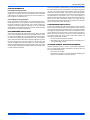
SECTION IX: WIRING DIAGRAM
FIGURE 13: Wiring Diagram (2 - 4 Ton)
16
Johnson Controls Unitary Products
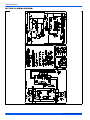
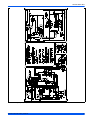
562156-UIM-A-0610
FIGURE 14: Wiring Diagram (5 Ton)
Johnson Controls Unitary Products
17
NOTES
Subject to change without notice. Published in U.S.A.
Copyright © 2010 by Johnson Controls, Inc. All rights reserved.
Johnson Controls Unitary Products
5005 York Drive
Norman, OK 73069
562156-UIM-A-0610
Supersedes: Nothing