1
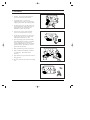
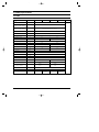
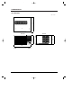
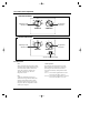
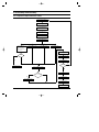
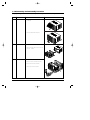
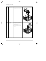
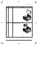
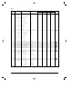
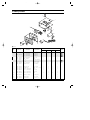
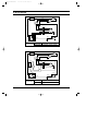
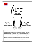
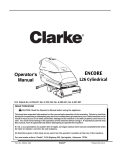
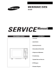
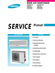
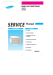
AW07A1SE/AW09A1SE-front
3/12/99 5:26 PM
Page 2
ROOM AIR CONDITIONER
AW07A0SE/AW07A1SE
AW09A0SE/AW09A1SE
SERVICE
AIR CONDITIONER
Manual
CONTENTS
1. Precautions
2. Product Specifications
3. Operating Instructions and
Installation
4. Disassembly and Reassembly
5. Troubleshooting
LOW
FAN
OFF
LOW
COOL
HI
FAN
6
4
8
HI
COOL
2
10
OPERAT
ION
12
COOLES
T
THERMO
STAT
6. Exploded Views and Parts List
7. Block Diagram
8. Wiring Diagram
AW07A1SE/AW09A1SE-1
3/12/99 5:27 PM
Page 1-1
1. Precautions
1. Warning: Prior to repair, disconnect the
power cord from the circuit breaker.
2. Use proper parts: Use only exact
replacement parts. (Also, we recommend
replacing parts rather than repairing them.)
3. Use the proper tools: Use the proper tools
and test equipment, and know how to use
equipment may cause problems laterintermittent contact, for example.
Fig. 1-1 Avoid Dangerous Contact
4. Power Cord: Prior to repair, check the
power cord and replace it if necessary.
5. Avoid using an extension cord, and avoid
tapping into a power cord. This practice
may result in malfunction or fire.
6. After completing repairs and reassembly,
check the insulation resistance, Procedure:
Prior to applying power, measure the
resistance between the power cord and the
ground terminal. The resistance must be
greater than 30 megohms.
Fig. 1-2 No Tapping and No Extension Cords
7. Make sure that the grounds are adequate.
8. Make sure that the installation conditions
are satisfactory. Relocate the unit if
necessary.
9. Keep children away from the unit while it is
being repaired.
10. Be sure to clean the unit and its surrounding
area.
Fig. 1-3 No Kids Nearby!
Fig. 1-4 Clean the Unit
Samsung Electronics
1-1
AW07A1SE/AW09A1SE-1
3/12/99 5:27 PM
Page 1-3
2. Product Specifications
2-1 Table
Item
Unit of Measure
Type
-
Window
mm (inch)
520 X 345 X 485 (20.5 X 13.6 X 19.1)
mm (inch)
571 X 449 X 546 (22.5 X 17.7 X 21.5)
Volt
220 - 240
-
Single
Dimensions:
(Width X Height X Depth)
Packing Size
AW07A0SE
AW07A1SE
(Width X Height X Depth)
Voltage:
Phase
Frequency
Hz
AW09A1SE
Operating Current
A
Power Consumption
W
750
FREON
4.5
1,000
R-22
g
410
420
KW
2.05
2.60
KW/Wh
2.05
2.6
Net Weight
kg
28
29
Condenser
Row
2 x 15
Condenser Fan
Type
Propeller Fan
Evaporator
Row
2 x 14
Evaporator Fan
Type
Blower
W
IC - 9630SWJ5B
Refrigerant Charge
Cooling Capacity
EER
Fan Motor
Compressor(Rotary)
Overload Protect
Compressor Capacitor
Model
44A070JW1E1
44B092JW1E5
-
MST24AMN - 12008
KRA1256 - 12007
25/370
µF/ VAC
Fan Motor Capacitor
20/370
Dual Type
-
Fan speed switch(High & Low)
Themo Control
-
Thermostat
Air Swing
-
-
Dual Type
3/370
2.5/370
Fan Speed Control
Samsung Electronics
Remarks
50
3.5
Refrigerant Type
AW09A0SE
M2LJ49ZR42
(5/6 RPM)
-
M2LJ49ZR42
(5/6 RPM)
2-1
AW07A1SE/AW09A1SE-1
3/12/99 5:27 PM
Page 1-4
2-2 Dimensions
2-2-1 Main Unit
485
Unit : mm
Front view
OFF
LOW
FAN
6
LOW
COOL
HI
FAN
345
345
Side view
HI
COOL
4
8
2
10
12
COOLEST
OPERATION
THERMOSTAT
520
2-2
Samsung Electronics
AW07A1SE/AW09A1SE-1
3/12/99 5:27 PM
Page 3-1
3. Installation and Operating Instructions
3-1 Installation
3-1-1 Selecting Area for Installation
1.
Make sure that you install the unit in an area
providing good ventilation. The air conditioner
must not be blocked by any obstacles affecting the
airflow near the air inlet and the air outlet.
2.
Make sure that you install the unit in an area that
allows good air handling. The installation area
must be able to endure vibration from the unit.
3.
Make sure that you install the unit away from heat
or vapor.
4.
Make sure that you install the unit in an area
which is cool and has adequate space.
5.
6. Make sure that you install the unit in an area which
provides easy drainage for condensed water.
7.
Make sure that you install the unit in area not
exposed to the rain or direct sunlight.
(Install a separate sunblind if exposed to direct
sunlight).
8. Make sure that you install the unit in an area
allowing good air movement. Do not install it in
a space that would cause noise amplification
of noise.
9.
Fix the unit firmly if mounted in a high place.
Make sure that you install the unit in an area away
from TVs, audio units, cordless phones,
fluorescent lighting fixtures and other electrical
appliances (at least 1 meter clearance).
Caution:
Do not use the air conditioner in the following environments : greasy areas (including areas near machines),
or marine areas. Contact your local dealer for advice.
Samsung Electronics
3-1
AW07A1SE/AW09A1SE-1
3/12/99 5:27 PM
Page 3-2
3-2 Controls and Components
<AW07A0SE/AW09A0SE>
OFF
LOW
FAN
Operating mode
selection dial
6
LOW
COOL
HI
FAN
8
4
HI
COOL
2
10
12
Temperature
control dial
COOLEST
OPERATION
THERMOSTAT
<AW07A1SE/AW09A1SE>
OFF
LOW
FAN
Operating mode
selection dial
6
LOW
COOL
HI
FAN
4
HI
COOL
8
2
10
12
Temperature
control dial
COOLEST
OPERATION
THERMOSTAT
Air flow blade swing switch
3-2-1 Thermostat
OFF :
When room temperature is lowered by the air
conditioner, the gas within the thermostat will
contract and cause a break in the electrical
contact. The compressor will then stop.
After the compressor stops, the room
temperature will rise.
ON :
As the room temperature increases to a
selected level, the gas within the thermostat
expands causing electrical contact, which
provides the source of electric power to the
compressor. The room temperature will fall
and the cycle will repeat.
3-2
Control Operation :
By turning the control knob clockwise (toward
higher numbers), the temperature will be cooler.
By turning the control knob counterclockwise
(toward lower numbers), the temperature will be
warmer.
Level 1 : Cool air will be supplied above 30~35¡C
Cool air will cease below 28~32.5¡C
Level 12 : Cool air will be supplied above 17.4~20.4¡C
Cool air will cease below 14.4~17.4¡C
Samsung Electronics
AW07A1SE/AW09A1SE-1
3/12/99 5:27 PM
Page 3-3
3-2-2 Operation
The fan selector switch offers high and low fan cooling control levels to assure maximum comfort.
The two fan speeds allow you to economically circulate room air flow on days when intense cooling is not required. When
combined with the thermostat(set to call for conditioned air), these controls cool, dehumidify, filter, and circulate room air,
with the fan continuing to circulate air even when the compressor is turned off.
3-2-3 Ventilation Control
Use the ventilation switch to exhaust unfresh air.
Open position : The air inside the room circulates, while exhausted is sent outside.
Closed position : The air inside the room circulates without exhaust.
3-2-4 Air Swing Switch(AW07A1SE/AW09A1SE)
¥ ON (
¥ OFF(
) : Automatic oscillation distributes the air flow throughout the room
(controls left and right wave fins)
) : Maintains a fixed direction of air flow, Set the Air Swing switch to OFF at the instant the wave
fins come to the desired position.
Samsung Electronics
3-3
AW07A1SE/AW09A1SE-1
3/12/99 5:27 PM
Page 4-1
4. Disassembly and Reassembly
4-1. Compressor Replacement Flow Chart
Locate cause of defect
Release refrigerant
Disconnect electrical
wiring from compressor
Cut refrigerant lines
from compressor
Plug disconnected lines
Replace compressor
Inspect electrical
wiring for defects,
and terminals for
correct and secure
connections
Solder discharge line
Solder suction line
Use nitrogen gas
Perform soldering function
Problem?
Fill system with nitrogen gas
Y
N
Check for leakage
Y
Leakage?
Corrective action
Check refrigerant oil level
N
Release nitrogen gas?
Low oil level?
Y
N
Evacuate system
Add oil as necessary
Recharge system
Pinch and braze filling tube
Samsung Electronics
4-1
AW07A1SE/AW09A1SE-1
3/12/99 5:27 PM
Page 4-2
4-2 Checking the oil
Put approximately 10cc oil into a transparent container and test it.
4-2-1 Oil quality
Oil Condition
Condition of
Refrigerant Cycle
Color
Odor
Normal
Straw Yellow
No Odor
Return with the system
Over-heated
Brown Color
-
Change the oil
Motor Damage
Dark Brown
Pungent oil
Change the oil
Remarks
4-2-2 Changing and adding refrigerant oil
1. Change the compressor - DO NOT recharge the oil as the compressor itself is
already charged.
2. Change the condenser .... add 50cc
3. Change the evaporator .... add 50cc
4. When the refrigerant is replaced .... add 30cc oil.
5. After vacuum is completed, the oil is filled through the high pressure side.
6. In the event of a refrigerant leak, generally it is not necessary to add oil.
(unless the oil has leaked significantly).
4-3 Refrigerant Oil Specifications
Model
Oil Charge
AW07A0SE
AW07A1SE
280cc
AW09A0SE
AW09A1SE
360cc
Oil specification
SONTEX 200LT
4-2
Samsung Electronics
AW07A1SE/AW09A1SE-1
3/12/99 5:28 PM
Page 4-3
4-3 Disassembly and Reassembly Procedure
Stop operating the air conditioner, and pull out the power cord before repair.
No.
①
Part name
Ass'y Grill
Procedures
Remarks
1. Pull the panel front and remove the screw
on the grille
2. Push the grille left side and pull up
➁
Ass'y Cabinet
1. Remove the two screws both side cabinet.
2. Pull the front both side, and remove the unit
from the cabinet.
➂
Ass'y Control
1. Remove the blade V and arm blade
2. Remove 2 screws, and earth wire screw.
3. Remove two lead wire assemblies.
4. Take out the control box forward.
Samsung Electronics
4-3
AW07A1SE/AW09A1SE-1
3/12/99 5:28 PM
Page 4-4
Disassembly and Reassembly
No.
Part name
Procedures
➃
Frame Up
1. Remove 6 screws on the Frame up
and remove the Frame up and the reinf
from case cond.
➄
Case Cond &
Propeller Fan
1. Remove two screws on the bottom side,
and 4 screws on the case cond.
Remarks
2. Pull up the case cond and separate the
cond case from the cond.
3. Remove the nut flange, and remove the
propeller fan
4-4
Samsung Electronics
AW07A1SE/AW09A1SE-1
3/12/99 5:28 PM
Page 4-5
Disassembly and Reassembly
No.
Part name
Procedures
➅
Cond Casing
1. Remove the cond casing
➆
Blower & Motor
1. Move the motor & blower toward the
evap, and lift up the motor & blower
from the frame low.
Samsung Electronics
Remarks
4-5
AW07A1SE/AW09A1SE-2
3/12/99 5:31 PM
Page 5-1
5. Troubleshooting
5-1 Special Precautions
5-1-1 Check the voltage of the of power source.
The input voltage shall be 220 - 240V~ / 50Hz
The air conditioner may not operate properly if the voltage is out of this range.
5-1-2 Check weak and fragile parts.
5-1-3 Check the connection of terminals.
5-1-4 When a malfunction occurs:
No
①
Malfunction
Check point
Compressor does not run. 1. check the thermostat position.
2. check the connection of the lead wire.
3. check the over load protector.
4. check the compressor.
Causes
1. Setting temp is lower than room temp.
2. Disconnection of the lead wire.
3. O.L.P is faulty
4. Compressor is faulty
➁ Motor does not run.
1. check the connection of the lead
wire & switch.
2. check the motor
1. disconnection of the lead wire
2. switch is faulty.
3. motor is faulty
➂ Low cooling capacity
1. check the refrigerant leakage.
2. check the evaporator condition
( freezing, blocked with dusts, etc. )
❈ Difference of temp. exists between
the suction side and the discharge
side at least 12°C
❈ Standard condition
Indoor : 27°C outdoor : 35°C
1. Caused by the pipe crack
2. shortage of refrigerant
3. clean the evaporator & air filter.
➃ Noise
1. check vibration of the pipe
2. check the propeller fan and blower
( not loose or broken ).
3. check bearing noise of the motor
4. check the compressor noise against
1. pipes are contact with the other parts.
2. the hex. nut is loose
3. the parts are broken
4. motor is faulty
5. compressor is faulty
that of other compressors.
Samsung Electronics
5-1
AW07A1SE/AW09A1SE-2
3/12/99 5:31 PM
Page 5-2
6. Exploded View and Parts List
22
23
20
25
24
26
1
3
2
4
5
6
9
8
13
10
7
14
28
18
19
11
16
21
12
17
15
27
6-1 Main unit
6-1
Samsung Electronics
AW07A1SE/AW09A1SE-2
3/12/99 5:31 PM
Page 5-3
■ Part List
Q'TY
No.
Code No.
Description
Remarks
Specification
AW07A0SE AW07A1SE AW09A0SE AW09A1SE
1
DB64 - 10158B
DB64 - 00014A
DB63 - 30158A
DB64 - 70093A
DB66 - 30191A
DB75 - 00001A
DB96 - 00045A
INLET - GRILL
INLET - GRILL
GUARD AIR FILTER
PANEL FRONT
BLADE - H PP
ASS’Y EVAP
ASS’Y EVAP
HIPS
8
9
10
DB90 - 00002B
DB66 - 30211A
DB66 - 30212A
DB66 - 70030A
DB67 - 50078A
DB31 - 00004C
11
12
13
14
15
16
17
18
2
3
4
5
6
7
19
20
21
22
23
24
25
26
27
28
1
1
1
HIPS
HIPS
PP
2 X 14
2 X 14
1
1
1
1
1
-
1
1
1
1
-
1
1
1
1
1
1
1
1
ASS’Y FRAME LOW
BLADE V
BLADE V, M
DAMPER
BLOWER
MOTOR
ASS’Y
HIPS
HIPS
PP
ABS
IC9430SWJ5B
1
1
1
1
1
1
1
1
1
1
1
1
1
1
1
1
1
1
1
1
DB67 - 50077A
DB90 - 00013B
DB90 - 00014C
DB61 - 00027B
DB75 - 00002A
FAN PROPELLER
ASS’Y CASE COND
ASS’Y FRAME UP
FRAME REINF
ASS’Y COND
ABS
PP
ASS’Y
PP
2 x 15
1
1
1
1
1
1
1
1
1
1
1
1
1
1
1
1
1
1
1
1
DB63 - 10388A
DB90 - 00004A
DB96 - 00046A
DB96 - 00009A
DB96 - 10736A
DB96 - 00008A
DB62 - 31953A
DB62 - 00009A
CAP DRAIN
ASS’Y BASE
TUBE CAPILLARY ASS’Y
TUBE CAPILLARY ASS’Y
ASS’Y TUBE-SUCTION
ASS’Y TUBE-SUCTION
TUBE-DISCHARGE
TUBE-DISCHARGE
CR
ASS’Y
ID 1.42 L1100
ID 1.3 L900
ASS’Y
ASS’Y
ASS’Y
ASS’Y
1
1
1
1
1
1
1
1
1
1
1
1
1
1
1
-
1
1
1
1
1
-
DB95 - 10065K
DB95 - 10065B
DB60 - 30028A
DB73 - 10027A
DB63 - 10504A
DB60 - 00001A
ASS’Y COMP
ASS’Y COMP
NUT WASHER
GROMMET-ISOLATOR
COVER TERMINAL
NUT-FLANGE
44A070JW1E1
44B092JW1E5
M8, ZPC
EPDM
NORYL, BLK
M5, SM20C
1
3
3
1
1
1
3
3
1
1
1
3
3
1
1
1
3
3
1
1
DB47 - 20001Y
DB47 - 20002U
DB90 - 00003A
DB93 - 00139A
–
–
–
OLP-POLYESTER
OLP-POLYESTER
ASS’Y CABINET
ASS’Y CONTROL M
ASS’Y CONTROL M
ASS’Y CONTROL M
ASS’Y CONTROL M
MST24AMN-12008
MRA12056-12007
ASS’Y
AW07A0SE
AW07A1SE
AW09A0SE
AW09A1SE
1
1
1
-
1
1
1
-
1
1
-
1
1
Samsung Electronics
6-2
AW07A1SE/AW09A1SE-2
3/12/99 5:31 PM
Page 5-4
6-2 Ass’y Control
2
1
4
6
5
3
7
9
8
10
12
13
11
■ Part List
Q'TY
No.
Code No.
Description
Remarks
Specification
AW07A0SE AW07A1SE AW09A0SE AW09A1SE
DB93 - 00139A
DB93 - 00139E
DB93 - 00139D
DB93 - 00139G
DB61 - 10202A
DB66 - 70031A
2501 - 001182
2501 - 001168
DB65 - 10008B
DB65 - 20065F
ASS’Y CONTROL M
ASS’Y CONTROL M
ASS’Y CONTROL M
ASS’Y CONTROL M
CASE CONTROL M
ARM - BLADE
C - OIL
C - OIL
CLIP - CAPACITOR
SWING MOTOR
AW07A0SE
AW07A1SE
AW09A0SE
AW09A1SE
SECC - M
ABS
2.5/25µF, 370VAC
3/30µF, 370VAC
SECC - P, TO.8
M2LJ49ZU32
1
1
1
1
-
1
1
1
1
1
1
1
1
1
1
-
1
1
1
1
1
1
10
DB34 - 90027C
DB47 - 20074A
DB64 - 70110A
DB64 - 40185A
DB64 - 40185C
DB64 - 50138B
SELECTOR S/W
THERMOSTAT
PANEL - CONTROL M
INLAY - CONTROL(C)
INLAY - CONTROL(C)
KNOB - TIMER ASS’Y
M250, 12HR
SRB - 315 - 4 - 8 - D
HIPS
TO.5 GRY
TO.5 GRY
ABS
1
1
1
1
2
1
1
1
1
2
1
1
1
1
2
1
1
1
1
2
11
12
13
DB34 - 90022A
DB39 - 10062U
DB65 - 10083A
SEESAW - SWITCH
POWER CORD
CLAMP CABLE
6A, 250V, 2Pin
UCP-2, 250V
NY66 DA - 5N
1
1
1
1
1
1
1
1
1
1
0
1
2
3
4
5
6
7
8
9
6-3
Samsung Electronics
AW07A1SE/AW09A1SE-2
3/12/99 5:31 PM
Page 7-1
7. Block Diagram
7-1 Refrigerating Cycle Block Diagram
PINCH PIPE
(SERVICE VALVE)
SUCTION LINE
DISCHARGE LINE
ACCUMULATOR/COMPRESSOR
EVAPORATOR
CONDENSER
CAPILLARY TUBE
PINCH PIPE
(SERVICE VALVE)
Samsung Electronics
7-1
AW07A1SE/AW09A1SE-2
3/12/99 5:31 PM
Page 8-1
8. Wiring Diagram
BLK
WHT
RED
THERMOSTAT
O.L.P
S
C
BLK
CAPACITOR
R
COMP
WHT
BLK
BLK
BLK
BLU
BLU
RED
RED
YEL
YEL
M
S
F.M
H
L
GRN/YEL
8
4 2
7
GRN
BLK
1
PLUG
SELECTOR - S/W
DIAGRAM-ELECTRIC
AW07A0SE
CAPACITOR : 2.5/25 uF x 370VAC
AW09A0SE
CAPACITOR : 3/30 uF x 370VAC
BLK
WHT
RED
THERMOSTAT
BLK
SEESAW-S/W
1
2
C
BLK
R
COMP
CAPACITOR
BLK
O.L.P
S
RED
G.M
RED
BLK
BLU
BLU
ORG
RED
YEL
YEL
M
S
F.M
H
L
GRN/YEL
ORG
BLK
8
4 2
7
1
BLK
PLUG
SELECTOR - S/W
DIAGRAM-ELECTRIC
Samsung Electronics
GRN
AW07A1SE
CAPACITOR : 2.5/25 uF x370VAC
AW09A1SE
CAPACITOR : 3/30uF x370VAC
8-1