1
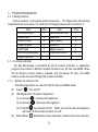
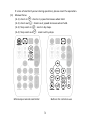
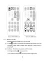
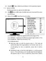
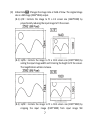
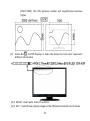
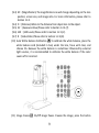
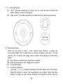
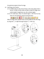
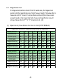
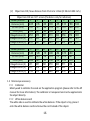
User’s Guide DiGi Microscope Version 1.2A Content 1. Products Introduction .......................... 2 1.1 Packing Contents ......................... 2 1.2 IR remote controller .................... 2 1.3 Microscope introduction: .......... 10 1.4 Microscope focus ....................... 13 1.5 Microscope accessory................ 16 2. Printed Notice .................................... 17 2.1 Maintenance .............................. 17 2.2 Product Specification ................. 18 2.3 Safety Instructions ..................... 19 1 1. Product Introduction 1.1 Packing Contents The box contains 1 microscope and 10 accessories. The Object Lens 4X is already assembled onto microscope; if it needs to be changed, please refer to Section 1.5. Item Q’ty Item Q’ty DiGi Microscope 1 White Balance Card 1 HDMI Cable 1 Calibrator 1 USB 2.0 Cable 1 User’s Guide 1 Power adaptor 1 Install CD 1 S107 Stand 1 Object Lens 4x 1 Stand assemble guide 1 IR Remote Control 1 Option Object Lens 10x 1.2 IR remote controller The Digi Microscope is controlled by the IR remote controller or application program and contains 3 different modes: Common Use, PC Cam and HDMI. When the far distance control mode is enabled, only the Power, PC Cam, and HDMI buttons can be accessed through the remote controller. 1.2.1 Buttons for Common Use The following buttons are used for both PC Cam and HDMI mode. (1) Power :Turn on/off. (2) LED Adjustment: 12 levels of brightness. (2-1) Increase :Increase LED brightness. (2-2) Decrease (3) :Decrease LED brightness. (2-3) On/Off :Turn the LED on/off. When turn on the LED, the brightness will return to the situation before turn off. Motor Reset (Recalibrates entire operation):Returns to the lens position. 2 (4) If a loss of electricity occur during operation, please reset the operation. Manual focus (4-1) Zoom in :Zooms in; speed increases when held. (4-2) Zoom out :Zooms out; speed increases when held. (4-3) Step zoom in (4-4) Step zoom out :zoom in by steps. :zoom out by steps. Buttons for common use Microscope remote controller 3 Buttons for PC CAM mode Buttons for HDMI mode 1.2.2 Buttons for PC CAM The following buttons are used only for PC Cam mode. (1) PC CAM :When in PC CAM mode, the USB cable must connect to a PC and microscope. Please disable software before switching to HDMI mode or powering off. (2) Autofocus:This function only operates on PC Cam mode. (2-1) Single Autofocus :Focuses one time. (2-2) Continuous autofocus :Re-focuses until the image is clear. 4 (3) Snapshot :Takes a 5M picture and delivers it to the application program. 1.2.3 Buttons for HDMI The following buttons are used only for HDMI mode. (1) HDMI :When in HDMI mode, the HDMI cable must connect with the screen and microscope. (2) Menu on Screen :Open/close menu for setting. (2-1) (2-2) (2-3) (2-4) BRIGHTNESS:Adjusts the brightness of the entire image. [1~31] CONTRAST:Emphasizes the difference between bright and dark. [1~31] SATURATION:Adjusts the color level. [1~31] EXPOSURE VALUE: [ON] Auto mode, use with the exposure value +/-. This mode will automatically adjust the image brightness. For the best result, turn on all LED lighting. For more on adjustment, please refer to Section 1.2.3-(7). [OFF] Manual mode, use with the LED brightness +/- and the exposure value +/-. This mode allows you to manually adjust the LED brightness and exposure value. For more on adjustment, please refer to Section 5 1.2.1-(2) and Section 1.2.3-(7). SHARPNESS: [ON] Sharpens the image. [OFF] Smooths the image. STATUS BAR: [ON] Displays the status bar on the top of screen. For more on the status bar, please refer to Section 1.2.3-(9). [OFF] Hides the status bar. (2-7) OBJECT LENS: Object lens type. (4x or 10x) Reset the settings whenever change another lens. Refer to Section 1.5. [4X] Object Lens 4x, turn on LED for lens 4x; in opposite, turn off LED for lens 10x. [10X]Object Lens 10x, turn off LED for lens 4x; in opposite, turn on LED for lens 10x. (2-8) LCD SIZE:Adjusts the screen size. The current setting is only for 7”~80”. (2-9) FACTORY: [NO] Stays on the current setting. [YES] Returns all settings to factory settings. (2-10)Vx.xx.xx:Firmware version. (2-5) (2-6) :Choose the previous item (3) Up (4) Down (5) Left (6) (7) Right :Choose the last value Exposure Value: 13 levels of exposure value are selectable, from +0.2~-2.0. (7-1) Increase :Use to increase exposure when the image is too dark. :Choose the next item :Choose the next value (7-2) Decrease :Use to decrease exposure when the image is too bright. 6 (8) Video Ratio :Changes the image ratio or Field of View. The original image size is a 5M image (2592*1944) output. (8-1) 4/3F:Formats the image to fit a 4:3 screen size (1440*1080) by proportionally reducing the input image to fit the screen. (8-2) 16/9S:Formats the image to fit a 16:9 screen size (1920*1080) by scaling the input image width and trimming the height to fit the screen. The magnification will also increase. (8-3) 16/9C:Formats the image to fit a 16:9 screen size (1920*1080) by cropping the input image (1920*1080) from input image 5M 7 (2595*1944). The FOV becomes smaller and magnification becomes higher. (9) Status Bar : On/Off Displays or hides the status bar. Each color represents different information. (9-1) ZOOM:Zoom path, totals 15 sections. (9-2) FOV:Field of View, display image on the effective horizontal size of screen. 8 (9-3) M:(Magnification) The magnification size will change depending on the lens position, screen size, and image ratio. For more information, please refer to Section 1.4.2. (9-4) D:(Distance) Refers to the distance from object lens to the object. (9-5) EV:(Exposure Value) Please refer to Section 1.2.3-(7). (9-6) LED:(LED Levels) Please refer to Section 1.2.1-(2). (9-7) R:(Video Ratio) Please refer to Section 1.2.3-(8). (10) Auto White Balance Calibration : To calibrate the white balance, place the white balance card (included in box) under the lens, focus until clear, and choose On. Because the white balance is sometimes influenced by external light sources, it is recommended to calibrate the white balance if the color seems off or incorrect. (11) Image Freeze : On/Off image freeze. Freezes the image; press the button 9 again to return to preview. (12) Sharpness : On/Off sharpness mode. Please refer to Section 1.2.3-(2). 1.3 Microscope introduction: 1.3.1 IR Remote Area/Indicator When both the HDMI and USB indicator lights are on, the microscope is in standby mode. Caution: Please remove the transparent protection sheet on the IR receiver area. a ○ b ○ (1) (2) (3) c ○ a : The indicator will blink whenever buttons IR remote control aiming area○ are pressed. The indicator will blink, if the indicator did not blink means the signal was not delivered and please repress again. b : When lit up, the device is in HDMI mode. HDMI indicator○ c : When lit up, the device is in USB mode. The light will flicker if USB indicator○ the microscope is not connected to a PC. 10 1.3.2 Power/USB/HDMI port d : Power supply is only compatible with the cord in the box. (1) Power○ d ○ (2) e : The USB cable is used to connect the microscope to a PC to access the USB○ application program. When the device is in PC Cam mode, connect the microscope to a PC through the USB cable from the box. Make sure to connect the USB cable first and then switch to PC Cam mode. e ○ 11 (3) f :The HDMI port is used to connect the microscope to a screen. When HDMI○ the device is in HDMI mode, connect the microscope to the screen using the HDMI cable from the box. * For TV screen connections, make sure to choose the homologous image ratio and format. f ○ 1.3.3 Stand gear box g on the Assemble the stand and then screw the microscope onto the universal joint ○ gear box. g ○ 12 1.3.4 LED/ Light socket h : Provides luminance for object lens 4x; total 30 LEDs (6 LEDS have (1) LED○ wider angles as shown in the figure). i : Provides luminance for object lens 10x. (Optional accessory) (2) Light socket○ h ○ i ○ 1.4 Microscope Focus There are two ways to focus. First, choose focus distance to adjust the microscope height, then tuning focus by remote controller until clear. On the contrary, first to choose the image sensor position then adjusts the microscope height. Focus distance: distance from object lens to object. Image sensor position: The image sensor position. 1.4.1 Focus Techniques (1) Fixed focus distance j or ○ k to adjust the distance from the object lens to the object. Use knob ○ When the distance is closer, the magnification size is higher. When the focus distance is fixed, use the remote controller or far distance control mode on 13 (2) the application program to focus the image. Fixed image sensor position (2-1) In HDMI mode, the status bar will show on the screen (please refer to Section 1.2.3-(9)). Use the remote controller to adjust the image sensor position based on magnification size, FOV, or distance height. (2-2) In PC CAM mode, choose the desired height or FOV from the drop down list in the application program (see figure below). When the image sensor position is fixed, as in (2-1) and (2-2), focus the image j to adjust the height and knob ○ k to fine tune. by using knob ○ j ○ j ○ k ○ k ○ 14 1.4.2 (1) Magnification chart 15 image sensor positions had set from the whole area, the image sensor position tells the magnification size, field of view, or height. The below chart is measured on 21.5” screen, it’s only a reference data, might not be accurate enough. Based on the image ratio, field of view and magnification size will change. Please refer to “F”, “S”, “C” in Section 1.2.3 – (8). Object lens 4X, focus distance from 2 cm to 22cm (0.787~8.66inch). Object lens 4X on 21.5” screen (this data is only for reference) Sensor position 1 2 3 4 5 6 7 Distance (cm) 21.8 18.1 11.1 8.02 6.37 5.25 4.46 F,S FOV (mm) 26.2 21.9 13.3 9.52 7.49 6.15 5.18 C FOV (mm) 19.4 16.2 9.80 7.04 5.54 4.55 3.83 F Magnification (X) 13 16 27 37 47 58 69 S Magnification (X) 17 21 35 49 62 77 91 C Magnification (X) 23 28 48 66 84 104 124 Sensor position Distance (cm) F,S FOV (mm) C FOV (mm) F Magnification (X) S Magnification (X) C Magnification (X) 9 3.49 3.99 2.95 89 118 160 10 3.13 3.56 2.63 100 133 180 11 2.85 3.22 2.38 111 147 199 15 12 2.62 2.94 2.18 121 161 217 13 2.44 2.71 2.01 132 175 237 14 2.26 2.50 1.85 143 190 257 15 2.13 2.34 1.73 152 202 273 8 3.91 4.52 3.34 79 105 142 (2) Object lens 10X, focus distance from 0.5mm to 1.0mm (0.196 to 0.393 inch.) Object lens 10X on 21.5” screen (this data is only for reference) Sensor position 1 2 3 4 5 6 7 Distance (mm) 9.85 9.35 9.00 8.65 8.35 8.10 7.88 F,S FOV (mm) 1.41 1.31 1.22 1.14 1.07 1.01 0.96 C FOV (mm) 1.04 0.97 0.90 0.84 0.79 0.75 0.71 F Magnification (X) 253 273 293 313 334 354 372 S Magnification (X) 337 363 390 417 445 471 495 C Magnification (X) 455 491 527 563 601 637 669 Sensor position Distance (mm) F,S FOV (mm) C FOV (mm) F Magnification (X) S Magnification (X) C Magnification (X) 9 7.46 0.87 0.64 411 547 739 10 7.28 0.83 0.61 431 574 775 11 7.10 0.79 0.58 452 602 813 12 6.96 0.76 0.56 470 626 846 13 6.84 0.73 0.54 490 653 882 14 6.74 0.70 0.52 511 681 919 8 7.66 0.91 0.67 393 523 707 15 6.64 0.67 0.50 534 711 961 1.5 Microscope accessory 1.5.1 Calibrator Mainly used to calibrate the scale on the application program (please refer to the AP manual for more information). The calibrator is transparent and can be applied onto the object directly. 1.5.2 White balance card The white side is used to calibrate the white balance. If the object is tiny, place it onto the white balance card and move the card instead of the object. 16 2. Printed Notice Please read the following information before operating. 2.1 Maintenance Please abide by the following rules while storing or using this product: 2.1.1 Keep dry: do not place the product in a humid environment. Dry surroundings help extend the life of the product. 2.1.2 Avoid temperature shock: temperature shock (for example, taking the product into a warm room from a cold environment) will cause internal condensation inside the machine. Please put the device inside the protection bag or handbag to prevent temperature shock, and avoid using the device in an environment with extreme temperatures. 2.1.3 Avoid dropping: the device may malfunction if it encounters strong collision, vibration, or distortion. 2.1.4 Turn the microscope off before cutting off the power supply : do not forced cut off the power supply. 2.1.5 Do not face the lens against strong light or sunshine for extended periods of time: Strong light rays may degrade sensitive elements and generate white stains on images. 2.1.6 Handle the device carefully: do not disassemble cables forcefully and avoid contact with the lens since they are subjected to damage. 2.1.7 Make sure to switch the power supply off and unplug the power cable if the device is not in operation for an extended period of time. Store the device in a dry envrionment with excellent ventilation. Do not expose the machine in an environment lower than -5ºC or higher than 50ºC. 2.1.8 While carrying, put the device inside the box to prevent it from being damaged. 17 2.2 Product Specification CMOS Sensor Lens Magnification Auxiliary source DC port HDMI port USB port Focus control Power supplier 5 million pixels CMOS senor Object lens 4X: 4/0.10,160/0.17; Object lens 10X: 10/0.25,160/0.17 Object lens 4X: 15x~270x; Object lens 10X: 260x~900x on 21.5” screen White LED × 30pcs Adaptor DC input Output 1080P(1920*1080 Pixel) image USB 2.0,3.0 compatible, connect with PC. IR remote controller/PC(application program) control adaptor (input:DC 5.0V/2.0A input:AC 100-240V 50/60Hz) Power Consumption (A/C) 0.225A (Max.) Size 106(L)×106(W)×152(T) mm Weight Host weight around 310 grams Temperature -5℃ ~ 50℃; Humidity-lower than 85% Operation environment (No Condensation) For any changes, please visit http://www.vitiny.com 18 2.3 Safety Instructions As an electronic product, please do not use the device in any place in which electronic products are prohibited. Keep the device away from water sources to avoid electric shock as it is not waterproof. Keep the device away from chemicals or substances with explosive or fire hazards. Switch the device off near gas stations. In the case that there are foreign substances or water inside the device, or the device is dropped or damaged, please switch off and remove the power supply to avoid fire and electric shock. Do not look steadily into Light sources after switching on the host as it is harmful to your eyes. Please use only the product accessories provided in the box for connections. Do not use any outside products without approval of original factory. Please remove the power supply from the microscope when not in use. Do not disassemble the machine for inspection. For any problems occurring in the machine itself, please power off the device and contact us through e-mail: [email protected] 19 Please ask the distributor to fill in the name of the shop, address, purchase date, and other contents to protect your rights and validate your one-year warranty since upon the purchase date. Contents of Warranty: The warranty is provided free of charge for faults caused by manufacturing within one year from the purchase date. Non-warranty: 1. Product appearance parts, such as the outer casing, knobs and LED cover, etc (charged spare parts are limited to one year after completing the product manufacturing). 2. Consumption goods of the host itself, such as LED lights and lens. 3. Product accessories and fittings, such as the power supplier, USB cable, HDMI cable, calibrator, white balance card, remote controller…etc. Services caused by any of the following situations in the period of the warranty shall not be provided free of charge: 1. Improper use or disassembly, repair or refitting. 2. Any damages to the device caused by external or environmental factors. 3. Discrepancy of product serial number, unfilled or unidentified warranty. Any inspection or repair service after the period of warranty will be charged as follows: (1) Service fees (including transportation fees) of product inspection. (2) Repair fees. (3) Fees of replaced parts ViTiny Service Center Tel: 07-657-9551 Fax: 07-657-9561 Address: 10 F., No.1, Section 1, Syuecheng Road, Dashu District, Kaohsiung City 840, Taiwan (R.O.C.) Website: http://www.vitiny.com ViTiny UM06 Warranty Product Model no S/L nos. Purchase d a t e Purchaser Te l DD/MM/YYYY no: Address Email Distributor Seal for Confirmation ( Stamp is necessary for validation of the Warranty ) ※Distributor’s seal shall include name of the shop, telephone and address※ HTTP://WWW.VITINY.COM © MicroLinks Technology Corp. All rights reserve