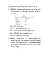
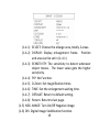
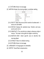
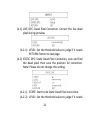
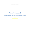
1
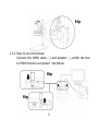
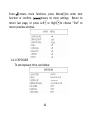
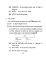
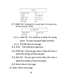
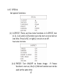
UM08 User’s Guide DiGi Microscope Version 1.0A Contents 1. Product Introduction ..........................2 1.1 Packing Contents ........................2 1.2 Assemble microscope with stand 2 1.3 IR Remote controller ...................4 1.4 Microscope menu functions........9 1.5 Microscope introduction:.......... 23 1.6 Microscope Focus ..................... 27 1.7 Microscope accessory ............... 31 2. Printed Notice .................................. 32 2.1 Maintenance ............................ 32 2.2 Product Specification ................ 33 2.3 Safety Instructions .................... 34 1 1. Product Introduction 1.1 Packing Contents The box contains 1 microscope and 8 accessories. The Object Lens 4X is already assembled onto microscope. Item DiGi Microscope HDMI Cable Power adaptor S107 Stand Stand assemble guide Q’ty 1 1 1 1 1 Item White Balance Card IR Remote Control User’s Guide Object Lens 4x Object Lens 10x Q’ty 1 1 1 1 Option 1.2 Assemble microscope with stand 1.2.1 Fix microscope Tighten the microscope onto stand ○,a. Refer to Stand assembling instruction for detailed explanation. 2 Błąd! 1.2.2 Start to use microscope Connect the HDMI cable ○,b and adaptor ○,c within the box to HDMI monitor and power. See below: Błąd! Błąd! 3 1.2.3 Power On/Off Press Power to turn on microscope. Choose HDMI mode or Auto on HDMI monitor to output image. 1.3 IR Remote controller The microscope operation and functions is controlled by the IR remote controller. (1) Power :Turn on/off. (2) HDMI :No Function. (3) PC CAM :No Function. (4) Snapshot :No Function. 4 (5) LED Adjustment: 12 levels of brightness. (5-1) Increase :Increase LED brightness. (5-2) Decrease :Decrease LED brightness. (5-3) On/Off :Turn the LED on/off. When turn on the LED, the brightness will return to the situation before turn off. (6) Motor Reset (Recalibrates entire operation):Returns to the lens position. If a loss of electricity occurred during operation, please reset the operation. (7) Manual focus (7-1) Zoom in :Zooms in; speed increases when held. (7-2) Zoom out :Zooms out; speed increases when held. (7-3) Step zoom in :zoom in by steps. (7-4) Step zoom out :zoom out by steps. (8) Autofocus: Press one time to search focus in current area, press and hold for 2 seconds to search focus in whole area. (8-1) Single Autofocus : Focuses one time. (8-2) Continuous autofocus :Re-focuses when image blurred. (9) Exposure Value: 18 levels of exposure value are selectable, from -9~Auto~+9. 5 (9-1) Increase :Use to increase exposure when the image is too dark. (9-2) Decrease :Use to decrease exposure when the image is too bright. (10) Menu on Screen :Open/close menu for setting. Refer to Section 1.4. (11) Up :Choose the previous item (12) Down :Choose the next item (13) Left :Choose the next value (14) Right :Choose the last value (15) Video Ratio :Digital zoom function can set x1.0, x2.0, x4.0, and x8.0. (16) Status Bar : Status bar tells Field of View (FOV), Magnification (MAG) or ON/OFF the status, see area ○,d. The area ○,e tells the operation status and only show 3 seconds. 6 Błąd! Błąd! (16-1) Area ○,d: (16-1-1) FOV:Field of View (FOV) display image on the effective horizontal size of screen. (16-1-2) MAG:(Magnification) The magnification size will change depending on the lens position, screen size, and image ratio. (16-1-3) WD: Working Distance. (16-2) Area ○,e: (16-2-1) OZ:Optical Zoom. Ex: OZ:↓500, ↓means zoom in, 500 means sensor position. (16-2-2) SZ:Step Zoom. Ex: SZ:↑500. Same format as OZ. (16-2-3) AFS:Single Autofocus. Ex: AFS►A500, “A” means 7 search focus in “current area”, 500 means sensor position. AFS►W500, “W” means search focus in “whole area”. (16-2-4) AFC:Continuous autofocus, “A” and “W” are same function as AFS. (16-2-5) LED:LED levels. Ex: LED:12, 12 means the LED level. (16-2-6) EV:Exposure Value. Ex: EV:↑5, means EV is +5, EV: ↓5 means EV is -5. (16-2-7) MR:Motor Reset. (16-2-8) DZ:Digital Zoom. Ex:DZ:x4.0 means digital enlarge 4x. (16-2-9) SHA:Sharpness. Ex: SHA►SET(5), means sharpness is 5. SHA►SET(15) means the maximum 15. (16-2-10) FRZ:Image Freeze. Ex: FRZ►ON, means freeze image, FRZ►OFF means unfreeze image. (16-2-11) WB:White Balance. Ex: WB►SET means calibrate white balance. (16-2-12) NONE:No Function. (17) Auto White Balance Calibration : To calibrate the white balance, place the white balance card (included in box) under the lens, focus until clear, and choose On. Because the white 8 balance is sometimes influenced by external light sources, it is recommended to calibrate the white balance if the color seems off or incorrect. (18) Image Freeze : ON/Off to freeze or unfreeze the image. (19) Sharpness : On/Off to set sharpness at Minimum and Maximum level. 1.4 Microscope menu functions There are 8 functions in menu, press Up and Down to choose item, Left and Right to turn on/off or adjust parameter. 9 Enter means more functions, press Menu to enter next function or confirm. means no more settings. Return to return last page, or press Left or Right to choose “End” to return preview window. 1.4.1 EXPOSURE To set exposure time, see below: 10 (1) Shutter: Digitally control amount of light, the amount is smaller the image is darker and the frame rate is also slower. (2) AGC (Auto Gain Control): auto control the brightness based on setting when light is not enough. (3) SENS-UP:Only available when item (2) AGC value is larger than 0, use to increase Senor to light’s sensibility. (4) Brightness Adjust image brightness. (5) D-WDR: Digital-wide dynamic range. Digitally adjusting exposure in areas of the frame to maintain optimum detail in both the shadows and highlights of the image. (6) DEFOG:De-Fog. When observing under strong light or special environment, use Defog function to see clear image. Below fig for De-Fog setting. (6-1) POS/SIZE:Adjust de-fog position and area. 11 (6-2) GRADATION:To set gradation levels near the edge of defog area. (6-3) DEFAULT:Return to default setting. (6-4) RETURN: Return to last page. 1.4.2 BACKLIGHT Press left/right button to choose turn on/off Backlight mode. (1) OFF:Disable backlight function. (2) WDR:Wide Dynamic Range. WDR allows an imaging system to correct for the intense back light surrounding a subject and thus enhances the ability to distinguish features and shapes on the subject. See below for setting WDR. (2-1) GAIN: Set WDR gain level to raise up brightness of darker image. (2-2) WDR OFFSET:Wide Dynamic Range OFFSET. (2-3) RETURN: Return to last page. 12 (3) BLC (Back Light Compensation) To adjust brightness for darker image in back light environment. (3-1) GAIN: To adjust brightness level. (3-2) AREA: Choose the back light compensation area and size. (3-3) DEFAULT: Return to default setting. (3-4) Return: Return to last page, or press left or right to choose “End” to return preview window. (4) HSBLC (High Suppress Back Light Compensation) To identify the over luminance area by backlight, and proceed masking the area. 13 (4-1) SELECT: Select the areas which needs to be adjusted. 4 areas are selectable. (4-2) DISPLAY: Display the selected area. (4-3) LEVEL: Set value to judge if the image is too bright. (4-4) MODE: Super back light compensation mode. (4-5) ALL DAY: Day mode. (4-6) NIGHT: Night mode. (4-7) BLACK MASK: Reverse the over exposed area (4-8) DEFAULT: Return to factory default setting. (4-9) RETURN: Return to last page. 1.4.3 MANUAL WB Calibrate the white balance. (1) AWB: Auto white balance. (2) ATW: Auto tracing white area and calibration. 14 (3) AWC->SET: Semi-auto white balance. Use to track the white color from current image. (4) MANUAL: Manually adjust blue and red values to find correct white color. Refer to below fig. 1.4.4 NR Noise Reduction:(NR) To obtain high quality output image and increase file compression. See below: (1) 2D NR:ON/OFF, Edge Preserving 2D NR. (2) 3D NR:ON/OFF, Motion Adaptive 3D NR. See below: 15 (3-1) SMART NR: Distinguish the moving object not moving noise, and auto close the “3D NR”. (3-1-1) SMART NR:The sensitivity to detect the moving object. The lower value gets higher sensitivity. (3-1-2) RETURN: Return to last page. (3-2) LEVEL:The threshold to judge noise. (3-3) START AGC:Start auto gain control. When AGC value is higher than setting, will start auto gain. (3-4) END AGC:End auto gain control. When AGC value is higher than setting, will end up auto gain. (3-5) Return: Return to last page. (3) Return: Return to last page. 16 1.4.5 SPECIAL Set special functions: (1) D-EFFECT: There are few more functions in D-EFFECT, but (1-3), (1-4) and (1-6) function can only turn on one item at one time. Press Left or right to turn on or off. See below functions: (1-1) FREEZE: Turn ON/OFF to freeze image. If Freeze function is turn on, the (1-2) Mirror function can not be used at the same time 17 (1-2) MIRROR: Image rotatory. (Horizontal or Vertical) (1-3) D-ZOOM: Digitally enlarge the chose area. Digital zoom selection can from 1-62 times. See below setting for D-Zoom. (1-3-1) PIP: No function. (1-3-2) D-Zoom: Set digital zoom times. (1-3-3) PAN&TILT: To set the enlarge position. (1-3-4) DEFAULT: Return to default setting. (1-3-5) RETURN: Return to last page. (1-4) SMART D-ZOOM: Assign 1 or 2 areas to enlarge the image from 1-62 times whenever detected the object moves. The Smart D-zoom will automatically enlarge the assigned area for few seconds and then return to original image. 18 (1-4-1) SELECT: Choose the enlarge area, totally 2 areas. (1-4-2) DISPLAY: Display enlargement frame. Position and area can be set in (1-4-1) (1-4-3) SENSITIVITY: The sensitivity to detect whenever object moves. The lower value gets the higher sensitivity. (1-4-4) PIP: No Function. (1-4-5) D-Zoom: Set magnification times. (1-4-6) TIME: Set the enlargement waiting time. (1-4-7) DEFAULT: Return to default setting. (1-4-8) Return: Return to last page. (1-5) NEG. IMAGE: Turn On/Off Negative image. (1-6) DIS: Digital Image Stabilization function. 19 (1-7) RETURN: Return to last page. (2) MOTION: Detect the moving object, see below setting. (2-1) SELECT: Select the areas which needs to be detected. 4 areas are selectable. (2-2) DISPLAY: Display the selected area. Position and area can be set in (2-1). (2-3) SENSITIVITY: The sensitivity to detect whenever object moves. The lower value gets the higher sensitivity. (2-4) MOTION VIEW:Mark specific area to identify the moving object. (2-5) DEFAULT: Return to default setting. (2-6) RETURN: Return to last page. (3) LANGUAGES: 16 languages are selectable. (4) DEFFECT: Dead Pixel compensation. 20 (4-1) LIVE DPC: Dead Pixel Correction. Correct the live dead pixel during preview. (4-2-1) LEVEL: Set the threshold value to judge if it needs RETURN: Return to last page. (4-2) STATIC DPC: Static Dead Pixel Correction, scan and find the dead pixel then save the position for correction. Note: Please do not change this setting. (4-2-1) START: Start to do Static Dead Pixel correction. (4-2-2) LEVEL: Set the threshold value to judge if it needs 21 to be corrected. (4-2-3) SENS-UP: Raise up the sensor’s sensitivity to compensate the dead pixel. (4-2-4) AGC: Auto Gain Control. When light is not enough, AGC will follow the threshold setting to compensate the dead pixel. (4-2-5) RETURN: Return to last page. (4-2-2) to be corrected. (5) VERSION: Firmware version. (6) RETURN: Return to last page. 1.4.6 ADJUST See image adjust as below fig. (1) SHARPNESS: Adjust Sharpness, higher value increases the higher contrast along/near edges of the image. (2) LSC:Lens Shading Correction. Use Lens shading correction to average the luminance of image. 22 1.4.7 RESET Return to factory default setting. Press Left/right button to choose “CHANGE” to return default. 1.4.8 RETURN Exit from menu. 1.5 Microscope introduction: 1.5.1 IR Remote Area/Indicator When both ○,g and ○,h LED indicator blinks, the microscope is in standby mode. Caution: Please remove the transparent protection sheet on the IR receiver area. 23 f ○ g ○ h ○ (1) IR remote control aiming area ○,f : The indicator will blink whenever buttons are pressed. If the indicator did not blink means the signal was not delivered and please repress again. (2) HDMI indicator ○,g:When lit up, the microscope is in HDMI mode. If light blinks, means microscope does not connect with monitor. 24 1.5.2 Power/USB/HDMI port Caution: Please hold the cable when remove from microscope and do not disassemble cables forcefully. i ○ Błąd! ○ Błąd! j k ○ i The HDMI port is used to connect the microscope to a (1) HDMI○,: screen. When the device is in HDMI mode, connect the microscope to the screen using the HDMI cable from the box. * For TV screen connections, make sure to choose the homologous image ratio and format. (2) USB○,j:USB port to use for future firmware update. (3) Power ○,K:Power adaptor is only compatible with the cord in the box. 25 1.5.3 Stand gear box Assemble the stand and then screw the microscope onto the universal joint ○,l on the gear box. Błąd! 1.5.4 LED/ Light socket (1) LED ○,m:Provides luminance for object lens 4x; total 30 LEDs. (2) Light socket ○,n : Provides luminance for object lens 10x. (Optional accessory) 26 Błąd! Błąd! 1.6 Microscope Focus There are two ways to focus. First, choose focus distance to adjust the microscope height, then tuning focus by remote controller until clear. On the contrary, first to choose the image sensor position then adjusts the microscope height. Focus distance: distance from object lens to object. Image sensor position: The image sensor position. 1.6.1 Focus Techniques (1) Fixed focus distance 27 Use knob ○,o or ○,p to adjust the distance from the object lens to the object. When the distance is closer, the magnification size is higher. When the focus distance is fixed, use the remote controller or far distance control mode on the application program to focus the image. (2) Fixed image sensor position The status bar will show on the screen (please refer to Section 1.3-(16)). Use the remote controller to adjust the image sensor position based on magnification size, FOV, or working distance. When the image sensor position is fixed, focus the image by using knob ○,o to adjust the height and knob ○,p to fine tune. 28 Błąd! Błąd! 1.6.2 Magnification chart 26 focus section setting is based on the whole focus area per 4x object lens. 10x object lens only have 15 focus sections. The sensor position tells the magnification size(Mag.), field of view(FOV), or working distance(WD). The below chart is measured on 4:3 ratio on 21.5” screen, it’s only a reference data, might not be accurate enough. Based on the image ratio (preview window size), field of view and magnification size will change. 29 (1) 4X object lens, focus distance from 22.5mm~226mm(0.885~8.897inch). 4X object lens on 21.5” (Reference data) Focus section 1 2 3 4 5 6 7 8 9 Sensor position 1615 1595 1565 1520 1460 1425 1380 1355 1325 WD(mm) 226 198 170 142 114 103 91.5 86.0 80.5 FOV(mm) 40 35 30 25 20 18 16 15 14 Mag. (X) 11.9 13.6 15.9 19.1 23.9 26.5 29.8 31.8 34.1 Focus section 10 11 12 Sensor position 1290 1250 1205 WD(mm) 75.0 69.5 64.0 FOV(mm) 13 12 11 Mag. (X) 36.7 39.8 43.3 13 1150 58.5 10 47.7 Focus section 19 20 21 Sensor position 885 815 730 WD (mm) 41.0 38.0 35.0 FOV(mm) 7 6.5 6 Mag. (X) 68.1 73.4 79.5 22 23 24 25 26 635 520 390 215 40 32.5 30.0 27.5 25.0 22.5 5.5 5 4.5 4 3.6 86.7 95.4 106 119 132 30 14 1115 55.5 9.5 50.2 15 1080 52.5 9 53.0 16 1040 49.5 8.5 56.1 17 995 47.0 8 59.6 18 940 44.0 7.5 63.6 10X object lens, focus distance from 6.2mm~10mm(0.244~0.393inch) 10X object lens on 21.5” (Reference data) Focus section 1 2 3 4 5 6 7 Sensor position 1850 1790 1720 1640 1550 1450 1340 WD (mm) 10 9.7 9.4 9.1 8.8 8.5 8.2 FOV(mm) 2.3 2.2 2.1 2.0 1.9 1.8 1.7 Mag. (X) 207 216 227 238 251 265 280 Focus section Sensor position WD (mm) FOV(mm) Mag. (X) 8 1220 7.9 1.6 298 9 1080 7.6 1.5 318 10 11 12 13 14 920 740 530 270 40 7.3 7.0 6.7 6.4 6.2 1.4 1.3 1.2 1.1 1.02 340 366 397 433 467 1.7 Microscope accessory 1.7.1 White balance card The white side is used to calibrate the white balance. If the object is tiny, place it onto the white balance card and move the card instead of the object. 31 2. Printed Notice Please read the following information before operating. Maintenance Please abide by the following rules while storing or using this product: 2.1.1 Keep dry: do not place the product in a humid environment. Dry surroundings help extend the life of the product. 2.1.2 Avoid temperature shock: temperature shock (for example, taking the product into a warm room from a cold environment) will cause internal condensation inside the machine. Please put the device inside the protection bag or handbag to prevent temperature shock, and avoid using the device in an environment with extreme temperatures. 2.1.3 Avoid dropping: the device may malfunction if it encounters strong collision, vibration, or distortion. 2.1.4 Turn the microscope off before cutting off the power supply : do not forced cut off the power supply. 2.1.5 Do not face the lens against strong light or sunshine for extended periods of time: Strong light rays may degrade sensitive elements and generate white stains on images. 2.1.6 Handle the device carefully: do not disassemble cables forcefully and avoid contact with the lens since they are subjected to damage. 2.1.7 Make sure to switch the power supply off and unplug the power cable if the device is not in operation for an extended period of time. Store the device in a dry environment with excellent ventilation. Do not expose the machine in an environment lower than -5ºC or higher than 50ºC. 2.1.8 While carrying, put the device inside the box to prevent from being damaged. 2.1 32 2.2 Product Specification CMOS Sensor Lens Magnification Auxiliary source DC port HDMI port Focus control Power supplier 2 million pixels CMOS sensor Object lens 4X: 4/0.10,160/0.17; Object lens 10X: 10/0.25,160/0.17 Object lens 4X: 12x~130x;1 Object lens 4X: 210x~460x on 21.5” monitor White LED × 30pcs Adaptor DC Input Output 1080P(1920*1080 Pixel) image IR remote control Adaptor (Output : DC 5.0V/2.0A Input : AC 100-240V 50/60Hz) 0.225A(Max) Power Consumption (A/C) Size 106(L)×106(W)×152(T) mm Weight Host weight around 310 grams Temperature -5℃ ~ 50℃; Humidity-lower than Operation environment 85% (No Condensation) For any changes, please visit http://www.vitiny.com 33 Safety Instructions As an electronic product, please do not use the device in any place in which electronic products are prohibited. Keep the device away from water sources to avoid electric shock as it is not waterproof. Keep the device away from chemicals or substances with explosive or fire hazards. Switch the device off near gas stations. In the case that there are foreign substances or water inside the device, or the device is dropped or damaged, please switch off and remove the power supply to avoid fire and electric shock. Do not look steadily into Light sources after switching on the host as it is harmful to your eyes. Please use only the product accessories provided in the box for connections. Do not use any outside products without approval of original factory. Please remove the power supply from the microscope when not in use. Do not disassemble the machine for inspection. For any problems occurring in the machine itself, please power off the device and contact us through e-mail: [email protected] 34 35 ViTiny UM08 Warranty Product Model no S/L nos. Purchase DD/MM/YYYY date Purchaser Tel no: Address Email Distributor Seal for Confirmation ( Stamp is necessary for validation of the Warranty ) ※Distributor’s seal shall include name of the shop, telephone and address※ Please ask the distributor to fill in the name of the shop, address, purchase date, and other contents to protect your rights and validate your one-year warranty since upon the purchase date. Contents of Warranty: The warranty is provided free of charge for faults caused by manufacturing within one year from the purchase date. Non-warranty: 1. Product appearance parts, such as the outer casing, knobs and LED cover, etc (charged spare parts are limited to one year after completing the product manufacturing). 2. Consumption goods of the host itself, such as LED lights and lens. 3. Product accessories and fittings, such as the power supplier, HDMI cable, white balance card, remote controller…etc. Services caused by any of the following situations in the period of the warranty shall not be provided free of charge: 1. Improper use or disassembly, repair or refitting. 2. Any damages to the device caused by external or environmental factors. 3. Discrepancy of product serial number, unfilled or unidentified warranty. Any inspection or repair service after the period of warranty will be charged as follows: (1) Service fees (including transportation fees) of product inspection. (2) Repair fees. (3) Fees of replaced parts ViTiny Service Center Tel: 07-657-9551 Fax: 07-657-9561 Address: 10 F., No.1, Section 1, Syuecheng Road, Dashu District, Kaohsiung City 840, Taiwan (R.O.C.) Website: http://www.vitiny.com HTTP://WWW.VITINY.COM © MicroLinks Technology Corp. All rights reserved.