1
PROFORM
CROSS TRAINER
TABLE
OF CONTENTS
IMPORTANT SAFETYPRECAUTIONS ...........................................................
BEFOREYOU BEGIN ......................................................................
ASSEMBLY....................................
. .........................................
ADJUSTING THE CROSS TRAINER e ..........................................................
OPERATING THE STEPPERCONSOLE .........................................................
1
2
3
8
10
OPERATING THE PERSONAL TRAINER COMPUTER...............................................
Calories ............................................................................
11
12
EXERCISEGUIDE ........................................................................
TROUBLE-SHOOTING AND MAINTENANCE ..................................................
ORDERING REPLACEMENTPARTS.....................................................
UMITEDWARRANTY ...............................................................
IMPORTANT
SAFETY
16
25
BackCover
Back Cover
PRECAUTIONS
WARNING: To reduce the risk of serious injury, read the following important safety precautions before using the
CROSSTRAINER e. Before beginning any exercise prngram, consultyour physician. This is especially important for
persons over the age of 35 or personswith pre-existing beal_ problems. PROFORM assumesno responsibilityfor
personal injury or property damage sustained by or through the use of this product.
1.
Read this owner's manual and the accompanying FI1NESSJOURNALcarefully before using the CROSSTRAINERe.
Use the CROSSTRAINER e only as described.
2.
Inspectand tighten all ports each time you use the CROSSTRAINERe. Replace any worn ports immediately.
3.
Do not use _
4.
Keep your hands away from moving parts. Always wear athletic shoes for foot protection.
5.
Keep small children away from the CROSSTRAINER • at all times.
6.
To prevent damage ta the weight system,do not put any pressureon the leg developer, arms or cables while the
weight selfing ischanging. If the lot bar or rower bar is attached ta the high pulley station, restit in the rack near the
high pulley station. (See OPERATINGTHEPERSONAL11UUNERCOMPUTERon page 11 of this owner's manual).
7.
Always stand on the foot plate when performing any exercise that could cause the CROSSTRAINERe to lip.
8.
Make sure that the cables remain in the grooves in the pulleys as you use the CROSSTRAINER e.
9.
The resistancecylinders become very hot during use. Allow the resistancecylinders to cool before touching
them. Cover the floor beneath the stepper for protection; o small amount of oil leakage is normal for hydraulic
transformer if it is damaged. Keep the power cord away from walkways and heated surfaces.
cylinders. When using the stepper, keep your feet on the pedals at all times. If you lift yonr feet off the pedals,
the pedals may become seporatecl from the resistancecylinders; resulting in injury.
10. If you feel pain or dizziness at any time while exercising, stop immediately and begin cooling down. Find out
what is wrong before continuing.
1
BEFORE
YOU
BEGIN
Congratulationsfor purchasing the revolutionary PROF<:::)RM
e CROSS TRAINER e. The CROSS TRAINER • combinesa
multi-stotionweight syslemwith a full-size stepperto let you enjoy Irue crosstraining workouts in the convenienceof
your own home. And to help you get the mosthorn everyworkout, the CROSS TRAINER • fealures the advanced PERSONAL TRAINERTM weight iralning computer.Whether your goal is improved cardiovascular illness,a shapely, toned
body or dmmatlc musclesize and strength, the CROSSTRAINER e will help you to achieve the specificresult_you want.
Foryour safety and benefit, mad Ibis owner's manual and the accompanylng FITNESSJOURNAL carefully before using
the CROSSTRAINER e. If you have additional questions,please call our Customer Service Deporlment tol_-freeat
1-800-999-3756, Monday through Friday, 6 a.m. until 6 p.m. Mountain Time (excluding holidays). To help usassist
you quickly, please note the model number and serial number of your CROSS TRAINER • before calling. The model
number is DR852040. The serial number can be found on a decal attached to the CROSS TRAINERe. The location of
He decal is shown in the drawing below. Write the serial numbe" in the following space for reference:
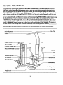
Beforereadingfurther, pleasereviewthe drawingbelow and familiarizeyourselfwith thepartsthat are labeled.
High PulleyStation.
Cable Clip
LatBar
Stepper Console
Stepper Handle
CUSTOM SMART CARD
Backrest
Arm
Seat
Resistance
Cylinder_
LegDevelopu,
Selector Knob
Serial No. Decal
Low PulleyStation
Foot Plate
WeightCoble.
2
ASSEMBLY
Assembly requires two persons.To assemblethe CROSS TRAINER e, usethe included videacassettoor follow the
instructionsbelow. Due to the weight of the CROSS TRAINER e, it shouldbe assembled in the location where it will be
used. Placeall parts in a cleared area and remove the packing materials. Do not dispose of the Packing materials until
assembly is completed. Make sure to lower the resistancecylinders and pedals before beginning assembly;,if the
resistance cylinders fall, Ihey may damage Ihe side shields. Read each assembly step and examine each drawing
carefully. Make sure that all parts are oriented as shown in the drawings.
The following tooJs (not included) ore required for assembly:, two 8' Adjustob.leWrenches _
Rubber Mallet _.
1.
and a
A small amount of soapy water is also requered.
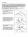
Set the Front Bose (7) and the Rear Base(8) on the
floor as shown. Tum the Rear Bose so the indented
holes are toward the floor.
Insertseven3/8" x 2 1/2" CarriageBolls(1) up
through the indicatedholesin theFrontand Rear
Bases(7, g}.
1
.
With the help of a secondperson, set the Tower
Frame (1 O) near the indicated ends of the Front and
Rear Bases(7, 8). The Tower Frame mustbe turned
so the Pedals (75, 76) are on the some side as the
extensionon the Front Bose. Raise the Tower Frame
and lower it onto the two indicated 3/8" x 2 1/2"
7
1
2
Carriage Bolls (1) in the Rear Bose.
76
Extension
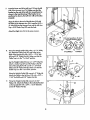
3.
Raise the front of the Tower Frame (10) and lower it
3
onto the two indicated 3/8" x 2 1/2" Carriage Bolls
(1) in the Front Base (7).
2
Adjust the position of the Tower Frame (1 O) so the
four indicated 3/8" x 2 1/2" Carriage Bolts(1) are
centered in the slottedhobs in the Tower Frame.
Thread a 3/8" Nut (2) with a 3/8" Lockwosher(3)
Extension
onto each Carriage Bolt. Do not tighten the Nuts
yet.
3
3
4. Slide the Brace (29) onto the threaded bolt protrud-
4
ing from the Tower Frame (10). Thread a 3/8"
N/lock Nut (6} onto the threaded bolt. Do not fighten the Nylock Nut yet.
Placeyour foot on the extension and slightlyraise
the _ont of the Tower Frame (10). Align the lower
end of the Brace (29) with the indicated 3/8" x
2 1/2" Carriage Bolt(1). Lower the Tower Frame so
the Brace slidesonto the Carriage Bolt. Thread a
3/8" Nut (2) with a 3/8" Lockwasher(3) onto the
Carriage Bolt. Do not tighten the Nut yet.
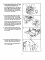
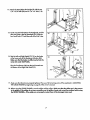
.
With the help of a second person, lift the Upright (9)
and lower it onto the two indicated 3/8" x 2 1/2"
Carriage Bolts (1) in the Rear Bose (8). Thread a
3/8" Nut'(2) and 3/8" Lockwasher (3) onto each
Carriage Bolt. Do not tighten the Nuts yet.
Attach the Front Bose (7) to the Upright (9) with two
3/8" x 3/4" Bolts (31).
Tighten the 3/8" Nylock Nut (6) attached in assembly step 4, and the seven 3/8" Nuts (2) attached in
assembly steps 3 through 5.
6.
9
Attach the Foot Plate (102) to the Upright (9) with
two 3/8" x 3/4" Bolts (31) and 3/8" N/lock Nuts
(61.
6
With the help of a secondperson, lift the Front Base
(7). Peel the backing off three Rubber Pods (48).
Presstwo onto the underside of the Front Base in the
48
indicated locations, and one onto the underside of
the Upright (9). Lower the Front Bose.
7
9
6
Presstwo Rubber Pads (48} onto the Rear Base(8)
in the some manner.
102
4
7.
Insertthe lower end of the LeftArm (15) into the left
side of the Moment Arm (74). Make sure that the
bracket on the end of the Left Arm is positioned as
shown in Iho inset drawing. If the bracket is not
positioned as shown, the Left Arm will not function
propq.'ly.
Align the hale in the end of the LeftArm (15) with
the holes in the Moment Arm (74). Insertthe 3/4" x
4" Axle (54) into the Moment Arm and the Left Arm.
Tap a 3/4'
\
15
PlasticCap (57) onto the Axle.
Attach the Right Arm (16) in the same manner.
/"
/
/
/
/
(_'_rrect position oF Arms
' against Moment Arm
8.
74
Wrap the Weight Cable (52) under a 3 1/2" Pulley
(5). Attach the Cable Trap (67) and Pulleyto the
back of the Upright (9) with a 3/8" x 1 3/4" Bolt
INCORRECT
(40) and 3/8" Nylock Nut (6). Make sure that the
Cable Trap is in the "7 o'clock_ position.
Lay the Weight Cable (52) aver a 3 1/2" Pulley(5).
Attach a Cable Trap (67) and the Pulleyto the [eft
side of the Upright (9) with a 3/8" x 1 3/4" Bolt
(40) and 3/8" Nylock Nut (6). Make sure that the
Cable Trap is in the "12 o'clock" position.
Wrap the Weight Cable (52) around a 2" Pulley(4).
Attach the Pulleyto the Left Arm (15) with a 3/8" x
1 3/4" Bolt(40) and 3/8" N/lock Nut (6).
°
40
67
5
5
67
Wrap the Weight Cable (52) around a 2 3/4"
Pulley(13). Attach the Pulleyto the indicated bracket
an the Upright (9) with a 3/8 = x 1 3/4" Bolt (40)
and 3/8" Nylock Nut (6).
9
5
CORRECT
10. Wrap the Weight Cable (52) around a 2" Pulley(4).
10
Attach the Pulley to the RightArm (16) with a 3/8", x
1 3/4" Bolt(40) and 3/8" Nylock Nut (6).
0
Lay the Weight Cable (52) over a 3 1/2" Pulley
(5).
Attach a CableTrap (67) and the Pulleytotheside
of the Upright (9) with a 3/8" x i 3/4" Bolt(40)
and 3/8" N/lock Nut (6). Make sure that the Cable
Trap is in the "12 o'clock" position.
11. Wrap the Weight Cable (52) under a 2" Pulley(4).
Attach the Pulleyto the bracket on the side of the
Moment Arm (74) with a 3/8" x 1 3/4" Bolt(40)
11
and 3/8' Nylock Nut (6). Make sure that the Weight
Cable is between the Pulleyand the indicated pin.
Attach the end of the Weight Cable (52) to the right
side of the Leg Developer (23) with a 3/8" x 2 1/4",
Bolt(45) and 3/8" Nylock Nut (6). Do not overtighten the Nylock Nut, the Cable must be able to swivel freely or it will be damaged.
] 2. Insertthe threaded bolt on the end of the Weight
Cable (52) into the AdjustmentBracket(53). Thread
12
the 5/16" Nut (82) exadty two completeturnsonto
the threaded bah.
13. Wet the upper ends of the Leftand Right Arms (15,
16) and the insidesof the two Large Pads (17) with
soapy water. Slide the Large Padsonto the Arms.
13
Attach the Backrest (19) to the Upright (9) with two
1/4", x 2 1/2, Bolls (46).
:"
_"_46
5
6
14. Attach the Seat (28) ta the Uprlght (9) wlth the two
1/4" x 3/4" Bolts(20) and a 1/4" x 2" Bolt (118).
14
15. Centerone PadTube (22) in theUpright(9), and the
otherPad Tube in the LegDeveloper(23). Slide
four Small Pads (171 onto the _ds of the Pad Tubes.
16. Restthe Leftand RightPedals(75, 76] on the hooks
at the lower endsof the Resistance
Cylinders(84).
Make sumthat the hooksam fully insertedinlo the
sameslolsunderIsethPedals.
16
84
Plug the Transformer (39) into the jack located near
the _oottomof the Right Side Shield (12).
76
17. Make sure that all parts are properly tightened. The use o_
c all remaining parts will be explained in ADJUSTING
THE CROSS TRAINER e, beginning on page 8 of this owneds manual.
18. Before using the CROSS TRAINER e, test the cables and the pulleys.Make sure that the cables are in the grooves
in the pulleys.
If the cablesdo not move smoothly over the pulleys, locate and correct the problem before using
the CROSS TRAINER e. If the cables are not properly muted, they will be damaged when used.
7
DJUSTING
THE
CROSS
TRAINER
e
The CROSS TRAINER e is designed to be changed ham stationto stationquickly and easily. The instructionsbelow
describe how each port of the CROSS TRAINER e can be adjusted. Pleaseread these instructionscarefully before using
the CROSS TRAINER e. Refer to poges 17 through 24 of this owner's manual to see how the CROSS TRAINER e should
be set up for each individual exercise.
IMPORTANT: For effective exercise, the CROSSTRAINER • must be set up correctly for each exercise. When attaching the lat bar, rower bar or strap, attach them direclly to the CROSS TRAINER• or use the chain to attach them;
make sure that the lat bar, rower bar or strap is in the correct starting position for each exercise. If there is any
slack in the cable or chain as you perform an exercise, the effectivenessof the exercise will be reduced.
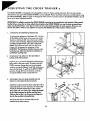
1.
CHANGING THE STEPPING RESISTANCE
To change the resistanceof the Pedals{75, 76), first
lift the Pedals off the hooksat the lower ends of the "
ResistanceCylinders (84}. Move the hooks to different slotsunder the Pedals.Make sure that the hooks
are fully inserted into the same slots under both
Pedals. The farther the hooks are from the Tower
Frame (10), the greater the resistancewill be.
WARNING: The ResistanceCylinders become very
hot during use. Allow the ResistanceCylinders to
cool before touching them.
2.
CHANGING THE ARMS TO THE BUTTERFLY
MODE AND PRESSMODE
The Arms (15, 16) can be changed to either the butterfly mode or the press mode. To perform the BUTTERFLYexercise, change the Arms to the butterfly
mode by turning the Selector Knob (55) clockwiseas
shown by the decal. To perform the BENCH PRESS
exercise, change the Arms to the pressmode by
turning the SelectorKnob counterclockwise.
3g
55
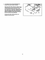
A'I'rACHING THE LAT BAR, ROWER BAR OR
STRAPTO THE HIGH PULLEY STATION
Attach the Lot Bar (36) to the Main Cable (51) with a
Cable Clip (33). For some exercises,the Chain (38)
shouldbe attached between the Lat Bar and the
Main Cable with two Cable Clips. Adjust the length
of the Chain between the bat Bar ond I_ Main
Cable so the tat Bar is in the correct starting position fortheexercise
tobeperformed.
The Rower Bor (34) or the Strap (35) can be
attached in the some manner.
8
4o
AITACHING THE EATBAR, ROWER BAR OR
STRAP TO THE LOW PULLEYSTATION
Attach the Lat Bar (36) to the Main Cable (51) with a
Cable Clip (33). For someexercises,the Chain (38)
shouldbe attached between the Lat Bar and the
38
Main Cable with two Cable Clips. Adjust Itm length
of the Chain between Itm Lat Bar and the Main
Cable so the Lat Bar is in the correct starting posl-
tionfor theexerclse
tobe perfarmed.
33
The Rower Bar (34) or the Strap (35) can be
attached in the same manner.
9
OPERATING
THE
STEPPER
CONSOLE
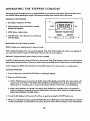
The stepper console is designed to give you instantfeedback as you exercise on the stepper. Please read theso instruclions carefully before opomling the console. Note: Removethe clear plasticfrom the front of the console.
DIAGRAM OF TIlE CONSOLE
1. LCD dlsplay--Display for all modes.
2. Mode indicators-Show which mode is currea_
selected
anddisplayed.
3. MODE button--Selects modes.
DIS'rANCE
MODE
4. ON/OFF button---Turnsthe power on and off, and
CALORIE
SCAN
ON/OFF
3
resetsthe display.
DESCRIPTION OF THE CONSOLE MODES
SPEED_Displays your stepping speed, in stepsper minute.
T_isplays
the length of lime you have been stepping. Note: Time will be counted only while you are stepping. If
you stop for ten secondsor longer, the TiME mode will pause until you resume stepping.
DISTANCE---Displays the total number of stepsyou have completed.
CALORIE--Displays the total number of Calories you have 10umed.Note: If the steppingresistanceis near the lowestor
highest setting,the actual numJ:_r of Caloriesyou have burned may be slightly lower or higher than the number displayed.
SCAN--Displays the SPEED,TIME, DISTANCE and CALORIE modes, for five secondseach, in a repeating cycle.
CONSOLE OPERATION
1. To turn on the power, pressthe ON/OFF bultonor simplybegin stepping.
2. Seled one of the five modes:
a. SCAN--When the power is turned on, the SCAN mode will be selected automatically. One mode indicator will
appear by the word 'SCAN." The SPEED,TIME, DISTANCE and CALORIEmodes will all be displayed, for five
secondseach, in a repeating cycle. A secondmode indicator will show which mode is currenlly displayed.
I0. SPEED,TIME, DISTANCE or CALORIE--The SPEED,TIME, DISTANCE or CALORIE mode con be selected for
continuousdisplay by repeatedly pressingthe MODE button.The modes will be selected in the following order:
SPEED,TIME, DISTANCE, CALORIE, SCAN.
3. To resetthe LCD display, turn the power off and then on again by pressingthe ON/OFF button twice.
4. When you are finishedexercising, pressthe ON/OFF buttonto turn off _ power. Note: If the pedals are not moved
and the €onsoJe bultonsare not pressed for _ur minutes,the powerwill turn off automaticallyto conservethe batteries.
10
OPERATING
THE
PERSONAL
TRAINER
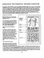
COMPUTER
The heart of the CROSS "IIU_NER e is the advanced PERSONA[.TRAINER weight Iraining computer.Wilh the PERSONAL TRAINER computer, you can change the weight seltingwith a touch of a bu#on. As you exercise, the computerwill
measure your range of motion, show the number of Calories you have burned and keep track of the repetitionsand
setsyou have completed. In Ibe trainer mode, you can select a specificmusclegroup, and the compufer will guide you
through a seriesof exercises_ will develop the selectod muscle group. Using the included CUSTOM SMART CARD,
you can create customexercise prngmms and storethem in memory for futureworkouts. PreprogrammedSMART
CARDS can also be purchased to help you achieve specificexercise goals. See the included brochure for more informarion. Please read Ihem imlru_m_ mrdully before _m_ing
the computer.
TURNING ON THE POWER
Hug the Iramformer into a 120-vaft outlet.
All indicators and displays on the computer
will flash three times.
PERSONAL
TRAINER
To turn on the power, pressthe POWER button. The four displays and various indicators
on the computer will light. The systemmotor
may be heard while the weight systemrecalibrates. Note: Always lure on the power
Computer
when using the CROSS TRAINER e.
chart
SELECTINGTHE TONE OR S'I1RENGTH
MODE
Displays
The PERSONAL TRAINER computeroffers
both a tone mode and a strength mode. If
your goal is to tone your musclesand develop ondumnce, the tone mode shoukJbe
selected. If you want to increase the size and
strengthoFyour muscles,the strength mode
Muscle
Stroke
Meter
Indicators
shouldbeselected.Whenthepoweris
turned on, the tone mode will be selected
automatically. The tone indicator will light.
To selectthe strengthmode, pressthe
STRENGTHbutton. The strength indicator will
Indicators
light.
USING THE MANUAL MODE
O
Whan the Power is lurned on, the camputer
will be in the manual mode. The lower port
of the computer shows 20 exercisesthat can
be performed on the CROSS TRAINER e. The indicator on exercise 1 will be flashing. Pressthe right or left arrow on
the NEXT button until the indicator is flashing on the first exercisethat you want to do. The number of the exercise that
you select will be shown in the CALORIES/EXERCISENO. display. Note: For help selectingan exercise, refer to the
musclechart on the upper port of the computer. Presson the musclegroup that you want to exercise_be sure to press
on the circled letter. As long as you continueto pre_ on the musclegroup, indicatorswill light on the lower port of the
computerto show you which exercise(s)will develop the selectedmuscle group.
11
Next, press theTONE or STRENGIH bunon, depending on whether you want Ibe first exerciseto be a _
or a _
exercise.The WEIGHT display willshowthe_
weight selting for the exercise that you have selected.
WARNING: The recommended v_ght selting may be too high or too low for you, depending upon such factors as
your _
size and physical condition, if you cannot complete the desired numbers of sets and repetitions, the
weight sufllng should be decreased. The weight setting can be changed by pressingthe increaseor decrease button
ber_
the WEIGHT display. Each time one of Ihe buttonsis pressed,the weight settingwill change by 1 pound. The
buttonscan be held down to change the weight seltingquickly. (Theweight range for the BENCH PRESSexercise is 30
to 250 ponnds;the weight range for _1 other exercisesis 15to 125 pounds.)
IM_RTANT:Wh_ d_ w_ht se_ngischanging,
_ motorwill beheardand_ SETS
andRIEPS
displays
willshow
a rapidly rotofing indicator. To prevent damage to I_ weight system,do not put any pressure on the leg developer,
orms or cables while the welght sefllng is chong'mg.If the lot ber or rower ber is attached to the high pulby stallon,
restit in the rack near _ high pulby station, if the computer sensespressure on the weight systemwhib I_ weight
senlng is changing, the WEIGHT display will show on error code {"EEE")for Iwo seconds, and Ibe weight selling will
stop changing. The WEIGHT display will then show the current weight setting. Make sure tlmt there is no pressure
on the leg dev_,
arms or cables. Pressthe increase or decrease button beneath the WEIGHT display again to
change the weight settingas desired. Wait for Ibe sound of the motor to stop before you continue.
The SETSand REPSdisplays will show the recommendednumbersOf setsond repetitions for the exercise that you have
selected. If desired, the number of sets or repetitionscan be changed by pressingthe increase or decrease bulton
beneath the SETSor REPSdisplay. Each time one oFthe buttonsis pressed, the number of sets or repetitionswill change
by 1. The range of setsis 1 to 9. The range of repetitionsis 2 to 20.
Begin the exercise that you have selected. (Refer to pages 17 through 20 of this owner's manual for information about
the proper form for the exercise.)During your first repetition, the computerwill measureyour range of motiorr--try to
move through the full range of motion for the exercise. During each following repetition, the STROKEmeter will show
your range of motiorr-_Ty to reach 100% during each repetition.As you exercise, the SETSand REPSdisplayswill show
the numbersof setsand repetitionsremaining to be completed.One tone will soundafter each repetition iscompleted,
two toneswill sound after each set is completed,and three toneswill so0nd after all repetitionsand sets have been completed. In addition, the CALORIESindicator will light,and the CAJ.ORIES/EXERCISE
NO. display will show the number of
Calories that you have burned.
IMPORTANT:For effective exercise, rest for 1 minute after each set if you are doing a tone exercise, and 3 minu_s
after each set if you am doing a slmngth exercise. Your body will bum Calories at all tlmes--at an increased rate
while you are performing repetitions, and at a decreased rote while yon are resting. As soon as you bugin the first
exercise, the computer will begin counting the Calories you are burning, both while you are performing repetitions
and while you are resting, in order to find the number of Calories you bum during your workout, note the number
that is shown us soonas you €ompleteyonr lost exercise.
After you have completed all of the repetitionsand setsfor the first exercise that you selected, pressthe right or left
arrow on the NEXT buttonto selectIbe nextexercise that you want to do. Repeat the procedure described above for the
next exercise. (Note: If you select an exercise that involvesonly one arm or leg, suchas the SINGLE LEG CURLexercise,
the numbersof repetitionsand setsshown in the SETSand REPSdisplays shouldbe performed once using the right arm
or leg, and once using the left arm or leg. After completingthe repetitionsand setsusing one arm or leg, pressthe right
arrow on the NEXT button, _
pressthe left arrow on the NEXT bul_, and then repeat the repetitionsand setsusing
the other arm or leg.) Selectas many exercisesas desired until your workout is completed.
USING
THE TRAINER
MODE
Pressthe TRAINER
_i_
i_
light.Next, referto themusclecharton the upperpartof tim computer.An indicatorwill be lightedon musclegroup"A." Ifyou went to exerciseo differentmusclegroupfirst,presson
thedesiredmusclegroup--be sureto presson thecircledletter.
_I
"_
_lJ
12
Once you have selmteclthe first musclagroup that you waat to exercise, mfm" to the lawer pad of the _.
_
m
mere indicatorswill be lighted, showingyou which exercise(s)to do to clevelopthe selecteclmusclegroup. One of the
indicators will be flashingto show you which exerciseto do first. If you want to skip the first exercise, pressthe right
arrow on the NEXT buuon until the indicator is flashing on the exercise _ you want to do first. The number of the
exercise will be shown in the CALORIES/EXERCISENO. display. Next, pressthe TONE or STRENGTHbutton, depending on whether you want the firstexercise to be a tone or a strengthexercise.The WEIGHT display will show the recommencledweight settingfor the first exercise. If desired, the weight settingcan be changed. Thiscan be done in the
same manner as when the computer is in the manual mode. The SETSand REPSdisplayswill show the recommended
numbers of setsand repetitionsfor the first exercise. If desired, the number of setsor repetitionscan be changed. This
can be clonein the same manner as when the computer is in the manual mode.
Begin the first exercise. As you exercise,the €ompu_" will providethe same feed!oockas when it isin the manual mode.
After you have completed all of the repetitionsand sets for the first exercise,pressthe right arrow on the NEXT bulton
to selectthe next exercise that you want to do. Do as many of the indicated exercisesas desired.
When you hard completedthe desi.redexercisesfor the first muscle group t_t you selected, presson the next muscle
group that you want to exercise.Do as many of the indicated exercisesas desired. Selectas many musclegroupsas
desired until your workout is completed.
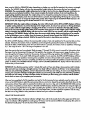
USING THE CUSTOM SMART CARD
CUSTOM
IMPORTANT: Before inserting or removing the
CUSTOM SMART CARD, press the POWER button 1olum off the power. Insertthe CUSTOM
SMART
SMART CARD into the left side of the computer.
Pressthe POWER button to turn on the power.
IMPORTANT:When the CUSTOM SMART CARD
is used, the exercise insert and the decal sheet
must be used or some weight settingswill not
be accurate.
The first step in creating an exercise program is
to select the exercises_ you want to include in
your first workout. Lay the exercise insert down
so the spacesnumbered 1 through 20 are on
top. Next, refer to pages 17 through 24 of this
owner's manual and select about 6 to 10 exercisesthat you want to include in the workout. For
each exercise that you select, apply a decal to
one of the first 6 to 10 spaceson the insert. I|
there is a printed decal for the exercise, apply
the printed decal; if there is not a printed decal,
apply a blank de_l and write the name of the
exercise on the decal. (Note: Whenever the
BENCH PRESSexercise is included in a workout,
the decal for the exercise mustbe applied to the
space numbered 1, 11, 21 or 31 on the insert. If
the BENCH PRESSexercise is not inclucled,those
t
0
_
p
0
I
0
0
0
•
_SNT
•
O
m
0
0
_
0
O
•
O
0
.._WE
N
O
•
s
O
,"4-/
I
0
_
0
•
0
I
0
i
spacesmustbe left emply.) Next, label all of the
decals on the insertwith a designation such as
"DAY 1." A sample workout is shownat the right.
13
After you have applied a decal to the exercise insertfor each of the exercism that you want to include in your first
workout, fit the four tabs on the insertinto the slob in the lower part of the computer. Make sure that the insertis turned
so the decals are visible. (The use of the remaining spaceson the insert will be explainedbelow.)
Next,a weight,setand repetitionselfingshouldbe programmedforeach of the exercises,
and theworkoutshouldbe
staredon theCUSTOMSMARTCARD.
Pressthe CREATEPROGRAM button. The indicator next to the button will light. Pressthe right or left arrow on the NEXT
button, if nec_sary, until the indicator is flashing on the first space on the exercise insertwhere a decal has been
applied. The number of the exercise will be shown in the C,AJ.ORIES/EXERCISE
NO. display. Next, pressthe TONE or
STRENGTH button, depending on whether you wont the first exerciseto be a tone or a sh'engthexercise.The indicator
next to the buttonyou presswill light. The WEIGHT, SETSand REPSdisplayswill show the recommendedweight setting
and numbers of sets and repetitionsfor the firstexercise.WARNING." The recommencledweight setting may be too
high or too low for you, depending on such factors as your body size and physical condition. If you cannot €on_
pleta the recommended numbers of sets and repetitions, I_ weight setting should be decreased. If desired, the
weight, set or repetition settingcan be changed by pressingthe increaseor decrease button below the WEIGHT, SETS
or REPSdisplay. The weight se,ing can be changed in incrementsof 1 pound; the buttons can be held down to change
the weight selting quiddy. The number of sets or repetitionscan be changed in incrementsof 1. The range of sets is 1 to
9. The range of repetitionsis 2 to 20. After you have programmed the desired weight, set and repetition settingsfor the
first exercise, press the STORE bulton. The indicator will remain lighted an the firstexercise an the exercise insert, and
the indicator will begin flashingan the next exercise on the insert. Pressthe TONE or STRFNGTH button and program
weight, set and repetition settings for the nextexercise as described above. Pressthe STORE button. Repeat for each of
the exercises on the insert.The workout will then be storedon the CUSTOM SMART CARD.
When you are ready to begin the workout, press the RUN PROGRAM button.The indicator next to the buttonwill light.
The indicators will light on all of the spacesan the exerciseinsertwhere decals have been applied. The indicator will be
flashing on the firstexercise of the workout. Begin the first exercise. (Refer to pages 17 through 24 of this owner's
manual for information about the proper form for the exercise.) As you exercise, the computer will provide the same
feedback as when it is in the manual mode. After you have completedall o| the sets and repetitionsfor the first exercise, press the right arrow on the NEXT button.The indicator will begin flashingon the nextexercise of the workout.
Performthe next exercise as described Qbove. Repeat until you have completed all of the exercises included in the
workout.
The workout can be revisedas your fitnesslevel increasesor your goQIschange. To revise the workout, first pressthe
CRF..ATEPROGRAM bulton. To revise the settings for an exercise, pressthe right or left arrow an the NEXT button until
the indicator is flashing on the exercise that you want to revise. Pressthe increase or decrease button below the
WEIGHT, SETSor REPSdisplay to change the setting. Pressthe STOREbutton. To delete on exercise, press the right or
left arrow on the NEXT bulton until the indicator is flashingon the exercise that you want to delete. Pressthe DELETE
button. Remove the decal for the exercise h'omthe exercise insert.To add an exercise, attach a decal to the insertand
pressthe right or left arrow on the NEXT button until the indicator is flashing on the new exercise on the insert. Program
weight, setand repetition seffings as described above. Pressthe STORE button.
Becausethem are 40 spaceson the exercise insert,a number of different workouts can be stored on the CUSTOM
SMART CARD at the same time. For example, your exerciseprogram could includethree different workouts--one for
Mondays, one for Wednesdays, and one for Fridays. Or, you could create two different workouts using the spaces
numbered 1 through 20 on the insert, and a training panner could create two different workouts using the spacesnumbered 21 through 40. To do one of the workouts, first pressthe RUN PROGRAM button. Pressthe right or left arrow on
the NEXT button until the indicator is flashing on the first exerciseof the workout that you want to do. Then, complete
the workout as described above. The CUSTOM SMART CARD can be programmed in a variety o| ways to fit your individual needs.
14
TURNING OFF THE POWER
To turn off the power, pressthe POWER button. Note: If no buttonson the computer are pressed for 30 minutes, the
power will turn off automal;cally. The transformershouldbe unplugged from the 120-volt outtetduring periodsof
nonuse.
15
EXERCISE
GUIDE
SAFETY
The CROSS TRAINER • is a tool, and learning to use it properly is essentialfor your safely as well as the successof
your exercise program. Read this owner's manual and the accompanying FITNESSJOURNAL carefully before using the
CROSS TRAINER e. Remember, the information in this owner's manual and in the FITNESSJOURNAL is general in
nature. For more information about exercise, consultyour physicianor obtain a reputable book about exercise.
WARNING: Before beginning any exercise program, consultyour physician. This is especially important for persons
over the age of 35 or persons with pre-existing
healthproblems.
THE FOUR BASIC TYPES OF EXERCISEPROGRAMS
STRENGTH
In order to increase the size and slmngth of your muscles,you mustsubjectyour musclesto above-normal workloads.
You mustalso progressivelyincrease the intensityof your exerciseso that your muscleswill continueto adapt and
grow. Each individual exercise con be tailored to the proper intensitylevel by changing the weight setting, or the number of repetitions or sets completed.The proper weight setting and numbers of sets and repetitionsfor each exercise
depends upon the individual user. Each workout shouldinclude about 6 to 10 different exercises. Selectexercises for
every major musclegroup, with emphasison the areas that you want to develop the mast. To give balance and variety
to your workouts, vary the exercisesfrom workout to workout. WARNING: If you are under age 17, workouts should
consistexclusively of tone exercises. Unsupervisedworkouts consistingexclusively of slrength exercises are not recommoncledby exercise physiologists.
TONING
To tone your muscles,select moderate weight settingsand increase the number of repetitions in each set. Work your
musclesby completing more repetitionsrather than by using high weight selfings.
LOSING WEIGHT
To lose weight, select low weight settings and increasethe number of repetitionsin each set. Exercisingon the stepper
will also help you to bum Calories and shed extra pounds.
CROSS TRAINING
In the pursuitof a completeand well-bolanced illnessprogram, many have found that crossh'aining is the answer. The
CROSS TRAINER e is ideal for crosstraining. By combining weight training with aerobic exercise, you con reshapeand
strengthenyour body, plusdevelop a strongerheart and lungs.
EXERCISEFORM
In order to obtoin the greotest benefitsfrom exercising, it is essentialto maintoin proper form. Maintaining proper form
means moving through the full range of motion for each exercise, and moving only the appropriate portsof the body.
On pages 17 through 24 of this owner's manual, you will find photographs showing the correct form for each exercise.
A descriptionof each exercise is also provided, along with a listof the muscles affected. Refer to the muscle chart in the
accompanying FITNESSJOURNAL to find the locationsof the muscles.As you exercise, the repetitionsin each set
shouldbe performed smoothlyand without pausing. The exertion phase of each repetition should lastonly about half
as long as the return phase. Restfor 1 minute after each set if you are doing a tone exercise, and 3 minutesafter each
set if you are doing a sh'engthexercise. Plan to spend the first two weeks learning the proper form for each exercise.
16
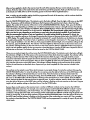
1.
BUTTERFLY
(15-125
Lbs.)
Musclesaffected: pectoralls major and minor, deltoids
Refer to adjuslmont 2 on page 8 of thisowner's manual. Change the arms to the buttmBy mnde. Sit on the seat and hold the pods on the arms as shown; your arms
shouldbe bent at 90* angles. Keep your back straight. Pressthe arms'together until
the pads touch. Returnto the starling position.
2.
BENCH
PRESS (30-250
Lbs.)
MusclesatTednd: pedoralis major and mlnor, anterior deltoids,
triceps
Refer to adjustment2 on page 8 of this owner's manual. Change the arms to Ibe
pressmode. Sit on the seat and hold the handles on the arms with an overhand grip.
Raiseyour elbows as shown. Keep your hack straight. Fullyextend your arms. Relum
to the starting position.
3.
FRONT
ARM
RAISE
(15-125
Lbs.)
Musc_oEected:
deltoids,
rhomboids
Referto adjustment 4 on page 9 of this owner's manual. Attach the strap to the low
pulley station. Stand with one heel on the foot plate. Hold the strap with an overhand
grip with your arm at your side. Keep your back straight. Raisethe strap until your
hand is level with your shoulderas shown. Returnto the starting position.
4.
UPRIGHT
ROW (15-125
Lbs.)
MuscLesaffected: biceps, deltoids, trapezius
Refer to adjustment 4 on page 9 oFthis owner's manual. Attach the rower bar to the
law pulley station. Stand with your feet on the foot plate. Hold the rower bar with an
overhand grip with your arms extended downward. Keep your back straight. IJfi the
rower bar untilyour hands are levelwith your chestas shown. Returnto the starting
position.
5.
SHOULDER
SHRUG
(15-125
Lbs.)
MusclesaEectnd:lrapezlus,rhomboids
Refer to adjustment 4 on page 9 of this owner's manual. Attach the rower bar to the
low pulley station. Stand with your feet on the foot plate. Hold the rower bar with an
overhand grip with your arms extended downward. Keep your back straight and
your arms at your sides.Shrug your shouldersup as far as possible. Returnto the
starlingposition.
17
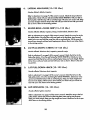
6.
LATERALARM
RAISE (15-125
Lbs.)
Muscles affected:deltoids, trapezius
Refer to adjustment4 on page 9 of thls owner's manual. Altach the strap ta II_ low
pulley station. Stand with your side toward the CROSS TRAINER • with your feet on
the foot plate. Hold the slmp with an overhand grip with your arm at your side. Keep
your back straight. Raise the strap to the side until your hand is level with your shoulder as shown. Returnto the startingposition.
7.
SEATED ROW--CLOSE
GRIP (15-125
Lbs.)
Musclesaffected:deltoids, trapezius, biceps, brachioradials, latissimusdersi
Refer to adjustment 4 on page 9 of this owner's manual. Attach the rower bar to the
low pulley station.Sit on the ft_0orwith your heelson the foot plate, lean forward,
extend your arms and hold the rower bar with an overhand grip. Pullthe rower bar
toward your stomachand lean back, keeping your elbows closeto your sides.Relum
to the starting position.
8.
LAT PULL-DOWN--CHEST
(15-125
Lbs.)
Musclesaffected: latissimus dorsi, trapezius, pedoralis major
Refer to adjustment 3 on page 8 of this owner's manual. Altach the lat bar to the
high pulley station. Sit on the seat facing the CROSS TRAINER e. Extendyour arms
upward and hold the lat bar with an overhand grip. Keep your back straight. Pullthe
lat bar down untilyour handsare legelwith your neck as shown. Returnto the starting position.
9.
LAT PULL-DOWN--BACK
(15-125
Lbs.)
Musclesaffected: latissimusdorsi, trapezlus
Refer to adjustment 3 on page 8 of this owner's manual. Attach the lat bar to the
high pulley station. Sit on the seat facing the CROSS TRAINER e. Extend your arms
upward and hold the lat bar with an overhand grip. Keep your back straight and
lean forward slightly. Pullthe lat bar down behind your head until your hands are
level with your neck. Relum to the starling position.
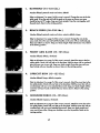
10.
HIP EXTENSION
(15-125
Lbs.)
Musclesaffected:gluteusmaximus
Refer ta adjustmeat 4 on page 9 of this owner's manual. Attach the slrap to the k_
pulley station. Stand with one foot on the foot plate. Insertone leg into the strap.
Keep your back straight. Keep your leg straight and move it backward as far as possible. Return to the startingposition.
18
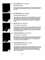
11.
LEG EXTENSION
(15-125
Lbs.)
Musclesaffected: quadriceps
Sit on the seat and positionyour feet under the pads on the leg developer. Keep your
back straight.Raise the leg developer until your legs are straight. Return to the starting position.
12.
HIP ABDUCTION
(15-125
Lbs.)
Musclesat_eded: abductor, gluteusmedius
Refer to adjustment4 on page 9 of this owner's mQnual. Attach the strap to the low
pulley station. Stand with your side toward the CROSS TRAINER e with or)e foot on
the foot plate. Insertyour outside leg into the strap. Keep your back straight.Keep
your leg straight and move it to the side as far as possible. Retam to the starting
position.
13.
BICEPS CURL (15-125
Lbs.)
Musclesat_eded: biceps, brachior_ials
Refer to acljustment ,4 on page 9 of this owner's manual. Attach the rower bar to the
low pulley station. Stand with your feet on the foot plate. Hold the rower bar with an
underhand grip with your arms extended downward. Keep your back straight and
your elbows close to your sides.Cud the rower bar up toward your chest as shown.
Returnto the startingposition.
14.
TRICEPS EXTENSION
(15-125
Lbs.)
Musclesot_.cted: triceps,brachioradials
Refer to adjustment3 on page 8 of this owner's manual. Attach the rower bar to the
high pulley station. Sit on the seat, hold the rower bar above your head and bend
your elbows. Keep your back straight and your elbows in. Slowly straightenyour
arms as shown. Returnto the startingposition.
15.
TRICEPS PRESS-DOWN
(15-125
Lbs.)
Musclesaffected: triceps, brachloradials
Referto adjustment3 on page 8 of this owner's manual. Attach the rower bar to the
high pulley station. Stand with your feet on the foot plate. Hold the rower bar with an
overhand grip with your hands at chestlevel. Keep your back straightand your
elbows close to your sides. Pressthe rower bar down until your arms am slraight.
Returnto the starting position.
19
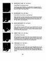
16.
SINGLE
LEG CURL (15-125
Mu_les otT_I:
Lbs.)
I_msh'ing,_strocnemius
Stand facing the CROSS TRAINER e and restthe back of one leg against the lower
pad on the leg developer. Raise the leg developer as far as possibleby bending your
leg as shown. Relum to the starting position.
17.
ABCRUNCH
(15-125
Lbs.)
Muscles alTm'tod:rectusabdominus, upper abdominals
Refer to.adjuslment3 on page 8 of thisowner's manual. Attach the strap to the high
pulley station.Sit on the seat and hold the sh'apbehind your head as shown. Keep
your back straight.Slowly bend forward at the waist until your upper body is at a
45 ° angle. Returnto the startingposition.
18.
BACK EXTENSION
(15-125
Lbs.)
Musclesaffected:hipextensors
Refer to adjuslment4 on page 9 of this owner's manual. Attach the lat bar to the low
pulley station. Sit on the floor with your heelson the foot plate. Crossyour arms and
hold the lot bar against your chestas shown. Keep your back straight.Bend back at
the waist. Relum to the starling positi.on.
19.
WRIST CURL (15-125
Lbs.)
Musclesaffected:brachloradials
Referto adjustment
4 on page 9 of this owner'smanual.Attachtherowerbar tothe
low pulleystation.Standwith yourfeeton the footplate.Holdthe rowerbar withan
overhandgripwithyourarmsextendeddownward.Keepyourarmsstationaryand
curlyourhandsup asfar aspossible.Returnto the startingposition.
20.
TOE RAISE (15-125
Lbs.)
Muscles affected:gastrocnemius
Refer to adjustment 4 on page 9 of this owner's manual. Altoch the rower bar to the
low pulley station. Stand with your feet on the foot plato. Hold the rower bar with an
overhand grip with your arms extended downward. Keep your back straightand
your arms at your sides. Riseup on your toesas far as possible. Return to the starling
position.
2O
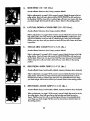
A.
SIDE BEND (15-125
Lbs.)
Musclesaffected: latissimusdorsi, biceps, posterior deltoids
Refer to adjustment4 on page 9 of this owner's manual. Attach lee strap to the !ow
pulley station. Stand with your side toward the CROSS TRAINER • with one foot on
Ifle foot plate. Hold the strap with an overhand grip with your arm at your side. Keep
your back sh'aight.Bendtoward the side as shown. Returnto the starling pasition:
B.
LAT PULL-DOWN--CLOSE
GRIP (15-125
Lbs.)
Musclesaffected:latissimus
dorsi,biceps,Posteriordeltoids
Refer to adjustment3 on page 8 of this owner's manual. Attach the rower bar to the
high puUey station. Sit on the seat facing the CROSS TRAINER e. Extendyour arms
upward and hold the rower bar with an underhand g_p. Keep your back straight.
Pullthe rower bar down until your hands are level with your neck. Relum to the starting position.
C.
SINGLE ARM CABLE FLY (15-125
Lbs.)
Muscles affected: latissimusdorsi, biceps, Posterior deltoids
Refer to adjustment3 on page 8 of this owner's manual. Attach the strap to the high
pulley station. Stand with your side toward the CROSS TRAINER • with one foot on
the foot Plate. Extend one arm upward and hold the strap. Keep your back straight.
Pull the strap down until your hand is level with your waist. Returnto the starting
position.
D.
BENT ROW--WIDE
GRIP (15-125
Lbs.)
Musdes atTected:biceps,brachioradials,deltoids,trapezlus, latissimusdorsi, rhomboids
Refer to adjustment4 on page 9 of this owner's manual. Attach the lat bar to the low
pulley station. Stand with your feet on the foot plate and bend forward as shown.
Hold the lot bar with on overhand grip with your arms extended downward. Keep
your back straight.Pullthe lot bar toward your stomach.Returnta lee startingposition.
E.
BENT ROW--CLOSE GRIP (15-125
Lbs.)
Musdes affected:biceps,brachioradlals,deltoids,h_apezius,latissimusdorsi,rhomboids
Refer to adjuslment 4 on page 9 of this owner's manual. Attach the rower bar to the
low pulley station. Stand with your feet on the foot plate and bend fo_vard as
shown. Hold the rower bar with an overhand grip with your arms extended downward. Keep your back straight. Pullthe rower bar toward your stomach.Return to
the starling position.
21
F.
SINGLE ARM BENT ROW (15--125
Lbs.)
_Musclesat_ecled:biceps,brachioradials,deltoids, h'apez.ius,lalissimusdorsi,rhomboids
Refer to adjustment
4 on page 9 of this owner's manual. Altoch the strap to the low
pulley station. Stand with your feet on the foot plc_ and bend forward as shown.
Hold the strap with on overhand grip with your arm extended downward. Keep your
back straight.Pullthe strap toward your stomach.Returnto the starting position.
G.
SEATED ROW--WIDE
GRIP (15-125
Lbs.)
Musclesaffected: deltoids, trapezius, biceps, brachioradials, latissimusdorsi
Refer to adjustment,4 on page 9 of this owner's manual. Attach the lot bar to the low
pulley station.Sit on the floor with your heelson the foot plate. Lean forward, extend
your arms and hold the lat bar with an overhand grip. Pullthe lot bar toward your
stomachand lean back. Returnto the startingposition.
H.
SINGLE ARM SEATED ROW (15--125
Lbs.)
Musclesaffecled:biceps,brachioradials,deltoids,trapezius,lalissimusdorsi,rhomboids
Refer to adjustment4 on page 9 of this owner's manual. Attach the strap to the low
pulley station. Sit on the floor with your heelson the foot plate. Lean forward, extend
one arm and hold the strap. Pull the strap toward your stomachand lean back, keeping your elbow closeto your side. Re'turnto the startingposition.
I.
REVERSEBICEPS CURL (15--125
Lbs.)
Musclesaffected:biceps, brachioradials
Refer to adjustment 4 on page 9 of this owner's manual. Attoch the rower bar to the
low pulley station. Stand with your heels on the foot plate. Hold the rower bar with
an overhand grip with your arms extended downward. Keep your back straight and
your elbows close to your sides.Curt the rower bar up toward your chestas shown.
Retain to the startingposition.
J.
ISOLATION
CURL (15--125
Lbs.)
Musclesaffected:biceps, brachloradials
Refer to adjustment 4 on page 9 of this owner's manual. Altach the strop to the low
pulley station.Stondwith your side toward the CROSS TRAINER e with one foot on
the foot plate. Hold the strap with on underhand grip with your arm extended clownward. Pullthe strap up until your hand is level with your chest. Retain to the starting
position.
22
K.
BENT ISOLATION CURL (15--125
Lbs.)
MusclesatTected:biceps, brachioradials
Rear to adjustment4 on page 9 oFthis owner's manual. Altach the strap to the low
pulley station. Stand with your side toward the CROSS TRAINER e, place one foot on
the foot plate and bend forward as shown. Hold the strap with an underhand grip
with your e[baw restingagainst your knee and your arm extended downward. Pull
the strap up until your hand is level with your chest. Returnto the starting position.
L.
REVERSE WRIST CURL (15--125
Lbs.)
Muscles
affec_l.,brach;oradials
Refer to adjustment4 on page 9 oFthis owner's manual. Attach the rower bar to the
law pulley station. Stand facing away from the CROSS TRAINER e with your heels on
the foot plate. Hold the rower bar behind your back as shown. Keep your arms stationary and cud your hands up as far as possible. Returnto the startingposition.
M.
REVERSE TRICEPS PRESS-DOWN
(15--125
Lbs.)
Musclesaffected: triceps, brachioradials
Refer to adjustment3 on page 8 of this owner's manual. Attach the rower bar to the
high pulley station. Stand with your feet on the foot plate. Hold the rower bar with an
underhand grip with your hands at chest level. Keep your back straightand your
elbows close to your sides.Pressthe rower bar down until your arms are straight.
Return to the startingposition.
N.
SINGLE ARM TRICEPS PRESS-DOWN
(15--125
Lbs.)
Musclesot_.cted: triceps, brachioradials
Refer to odiuslment3 on page 8 of this owner's manual. Attach the strap to the high
pulley station. Stand with your feet on the foot plate. Hold the strap with an overhand
grip with your hand at chest level. Keep your back straight and your elbow close to
your side. Pressthe strap down until your arm is straightas shown. Returnto the
starting position.
0.
REVERSE UPRIGHT
ROW (15--125
Lbs.)
Musclesaffected: biceps, deltoids, Irapezius
Refer to adjustment4 on page 9 of this owner's manual. Attach the rower bar to the
low pulley station. Stand facing away from the CROSS TRAINER e with your heelson
the foot plate. Hold the rower bar behind your back with your arms extended downward. Liftthe rower bar up as far as possible. Returnto the starting position.
23
P.
BENT LATERAL ARM RAISE (15-125
Lbs.)
MusclesaFfeded:deltoids,trapezius
Refer to adjustment4 on page 9 of this owner's manual. Altach the strap to the low
pulley station. Stand with your side toward the CROSS TRAINER e, place one foot on
the foot plate and bend for_vardas shown. Hold the strap with an overhand grip
with your arm at your side. Keep your back straight. Raise the strap to the side until
your hand is level with your shoulder. Returnto the starting position.
Q.
DEAD LIFT(15-125
Lbs.)
Musclesaffected: quadriceps
Referto adjustment4 on page9 of this owner'smanual.Attach the lat bar to the low
pulleystation.Standwith yourfeetonthe footplateand bendyourknees:asshown.
Holdthe lat bar withan overhandgrip. Keepyour headupand yourarmsand back
straight.Liftthelat bar by straightening
yourlegs.Returntothe startingposition.
R.
HIP ADDUCTION
(15-125
Lbs.)
Musclesaffected:adductor, gluteusmedius
Refer to adjustment4 on Page 9 of this owner's manual. Attach the strap to the low
pulley station. Stand with your side toward the CROSS TRAINER e with one foot on
the foot plate. Insertyour inside leg into the strap. Keep your back straight. Keep
your leg straightand move it to the s?deas far as Passible. Returnto the starting
position.
S.
FRONT KICK (15-125
Lbs.)
Musclesaffected: hip flexors, sortorius
Refer to adjustment 4 on page 9 of this owner's manual. Attach the strap to the low
pulley station. Stand facing awoy from the CROSS TRAINER e with one heel on the
foot pIQte.Insertone leg into the strap. Keep your leg straight and move it away from
the CROSS TRAINER e as far as passible. Returnto the starting position.
STEPPER
MusclesAffected: quadriceps, hip extensors
(Note: Do not includethis exercise in workoutscreated with the PERSONALTRAINER
computer.When the STEPPERis used, the stepperconsolewi!l provide feedback.)
Refer to adjuslment 1 on page 8 Of this owner's manual. Hold the stepperhandle and
begin stepping, alternately pressingthe left and right Pac_ls down with a smooth,
continuousmation---a continuousmotion mustbe maintained or bath pedals will sink
to the floor. Adjust the steppingresistanceif necessary.
24
TROUBLE-SHOOTING
AND
MAINTENANCE
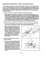
inspectand tighten all parts each time you usethe CROSS TRAINER e. Replace any worn parts immediately. Outside
surfaces of the CROSS TRAINER • can be cleaned using a damp cloth and mild detergent. Keep all liquidsaway from
Ihe stepper consoleand the PERSONALTRAINERcomputer.Most CROSSTRAINER• problems can be solved by following Itm stepsbelow. Find the applicable symptomand follow the step(s) listed. If further assistanceis needed, .callour
CustomerService Deporlment tall-free at 1-800"999-3756,
Time (excluding holidays).
Monday through Friday, 6 a.m. until 6 p.m. Mountain
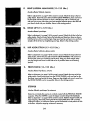
1. SYMPTOM: THE PERSONAL TRAINER COMPUTER DISPLAYS AN ERROR CODE ("EEE")
a. While theweight sefllngischanging, _
motorwill be heard and the SETSand PEPSdisplayswill show a rapidly
rotating indicator. To prevent damage ta.the weight system,do not put any pressurean the leg developer,arms
or cableswhile the weight settingis cbanglng. If the lat bar or rawer bar is attached to the high pulley station,restit
in the rack near the high pulley station.Wait for the soundof the motor to stop before you continue. IFthe computer sensespressure on the weight systemwhile the weight settingis changing, the WEIGHT display will show an
error code ("EEE') for two seconds,and the weight settlng will stopchanging. The WEIGHT display will then show
the current weight setting. Make sure that there is no pressureon the leg developer, arms or cables. Pressthe
increaseor decrease buttan beneath the WEIGHT display to change the weight seltingas desired.
2. SYMPTOM: THE MAIN CABLE DOES NOT MOVE SMOOTHLY, OR THERE IS SLACK IN THE MAIN CABLE
a. Inspectthe routingof the cables and make sure that they are in the grooves in all of the pulleys.If they are not,
correctthe problem. If the cables are not properly routed, they will be damaged when used.
b. If there is slack in the Main Cable (51), locate the
AdjustmentBracket(53) near the bottom of the
right side shield.Hold the end of theWeight Cable
53
52
S
{52) firmly, and slide the AdjustmentBracket farther onto the Weight Cable. Tightenthe 5/16" Nut
(82) against the AdjustmentBracket.Testt_ Main
Cable. If the motar stalls or hesitates,loosen the
5/16" Nut slightly. If the 5/16" Nut is tightened as
far as possibleand there is stillslack, the Main
Cable shouldbe replaced. See ORDERING
REPLACEMENTPARTSan the back cover of this
_*Tl_l
S monuol.
3. SYMPTOM: THE STEPPERCONSOLE DOES NOT
FUNCTION PROPERLY
a.
youstep,movethestepper
pedals
verticallyat
/
least8 inches. If your stepsare too shallow, the
movementof the stepperpedals will not be detected. If the stepper consolestilldoes not function
properly, the Reed Switch (99) can be adjusted
by
sliding the barrel of the Reed Switch up and down
slightly. Repeat until the stepperconsole displays
correct feedback. If necessary,the 3/4' Screw
(119) at_:hing the Reed Switch Bracket (120) can
be loosenedand the position oFthe Bracketcan be
/
119
adjusted.
25
99
\
/V_ounting
eeve
b°
If the LCD display becomesdim, the 1.5-voh watch
balteries in the Stepper Console (88) shouldbe
replaced. Using a short phillipsscrewdriver,
Backof
Ste_
Console
remove the two screws attaching the back of the
StepperConsole. Using the screwdriver, carefully
push the two batteries out of the battery clips; be
careful to note which way the batteries are turned.
Inserttwo new 1.5-volt watch batteries into the
1.5-Voh
Watch
Batteries
battery clips. Reattach the back of the Stepper
Console.
4.
SYMPTOM: THE POWER DOES NOT TURN ON
a.
Make surethat the lransformerisfully plugged intothe jack on the CROSS TRAINERe, and into a 120-voh outlet.
© 1994 Proform Fitness Products, Inc., a Subsidiary of Welder Health and Fitness,Inc.
26
ORDERING
REPLACEMENT
PARTS
To order replacement parts, simply call our CustomerServiceDepartment toll-free at 1-800-999-3756, Monday
through Friday, 6 a.m. until 6 p.m. Mountain Time (excluding holidays). To help usassistyou quickly, please be prepared to give the following information:
1. The MODEL NUMBER of the product (DR852040).
2. The NAME of the product (PROFORM®CROSSTRAINERe).
3. The SERIALNUMBER of the product (see BEFOREYOU BEGIN on page 2 of this owner's manual).
4. The KEY NUMBER and DESCRIPTIONof the part(s) from the PARTUST/EXPLODEDDRAWING accompanying this
owner's manual.
I
LIMITED
WARRANTY
Proform FitnessProducts,Inc. ("PROFORM") extendsa limi_l ten (10) year warranty on the frame and steel
parts. PROFORM warrants this product to be free from defects in workmanship and material, under normal
use and serviceconditions, for a period of ninety (90) days from the date of purchase. This warranty extends
only to the original purchaser. PROFORM'sobligation under this warranty is limited to replacing or repairing,
at PROFORM's option, the produd at one of its authorized service centers. All productsfor which warranty
claim is made mustbe receivedby PROFORM at one of itsauthorized service centers. All returnsmustbe preauthorized by PROFORM. This warronly does not extend to any product or damage to a productcaused by
or atlributeble to freight damage, abuse, misuse,improper or abnormal usage or repairs not provided by a
PROFORM authorized service center or for productsused for commercial or rental purposes. No other warranty beyond that specificallysetforth above is authorized by PROFORM.
PROFORM IS NOT RESPONSIBLEOR UABLEFOR INDIRECT, SPECIAL OR CONSEQUENTIAL DAMAGES
ARISING OUT OF OR IN CONNECTION WITH THE USE OR PERFORMANCE OF THE PRODUCTOR OTHER
DAMAGES WITH RESPECTTO ANY ECONOMIC LOSS, LOSS OF PROPERTY,LOSS OF REVENUES OR
PROFITS, LOSS OF ENJOYMENT OR USE, COSTS OF REMOVAL, INSTALLATION OR OTHER CONSEQUENTIAL DAMAGES OF WHATSOEVER NATURE. SOME STATES DO NOT ALLOW THE EXCLUSION OR
LIMITATION OF INCIDENTAL OR CONSEQUENTIAL DAMAGES. ACCORDINGLY, THE ABOVE UMITA11ON
MAY NOT APPLYTO YOU.
THE WARRANTY EXTENDED HEREUNDERiS IN UEU OF ANY AND ALL OTHER WARRANTIES AND ANY
IMPUED WARRANTIES OF MERCHANTABIUI"Y OR FITNESSFOR A PARTICULARPURPOSEIS UMITEDIN ITS
SCOPE AND DURATION TO THE TERMS SET FORTH HEREIN. SOME STATES DO NOT ALLOW UMITA"lIONS ON HOW LONG AN IMPUED WARR,_CC/YLASTS. ACCORDINGLY,_THE ABOVE UMITATION MAY
NOT APPLY TO YOU.
This warranty
gives you specificlegal rights. You may also have other rights which vary from stateto stale.
PROFORM FITNESS PRODUCTS,INC., 1500 S, 1000 W., LOGAN UT 84321-9813
PaflNo. 117164 R494B
Printed in USA