1
_vertible
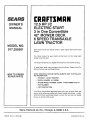
S_EA/ S
OWNER'S
MANUAL
MODEL NO.
917.255581
CRI:IFTZMIIN+
12.5 HP I/C
ELECTRIC START
3 in One Convertible
42" MOWER DECK
6 SPEED TRANSAXLE
LAWN TRACTOR
Caution:
Read and follow
all Safety Rules
and Instructions
Before Operating
This Equipment
• Assembly
, Operation
• Customer Responsibilities
° Service and Adjustment
° Repair Parts
!r
Sears, Roebuck and Co., Chicago, IL 60684 U.S.A.
SAFETY RULES
Safe Operation Practices for Ride-On Mowers
IMPORTANT: THIS CU-I-NNG MACHINE IS CAPABLE OFAMPUTATING HANDS AND FEETAND THROWING OBJECTS.
FAILUR E TO OBSERVE THE FOLLOWING SAFETY INSTRUCTIONS COULD RESULT IN SERIOUS INJU RY OR DEATH.
1.
GENERAL
-
Read, understand, and follow all instructions in the manual
and on the machine before starting.
Only allow responsible adults, who are familiar with the
instructions, to operate the machine.
Clear the area of objects such as rocks, toys, wire, etc.,
which could be picked up and thrown by the blade.
Be sure the area is clear of other people before mowing. Stop
machine if anyone enters the area.
Never carry passengers.
Do not mow in reverse unless absolutely necessary. Always
look down and behind before and while backing.
Be aware of the mower discharge direction and do not point
it at anyone. Do not operate the mower without either the
entire grass catcher or the guard in place.
Slow clown before turning.
Never leave a running machine unattended. Always turn off
blades, set parking brake, stop engine, and remove keys
before dismounting.
Turn off blades when not mowing.
Stop engine before removing grass catcher or unclogging
chute.
+
,,
•
•
=
=
,,
,,
+
=
•
+
•
II.
OPERATION
•
I11. CHILDREN
Tragic accidents can occur if the operator is not alert to the
presence of children.
Children are often attracted to the
machine and the mowing activity.
Never assume that
children will remain where you last saw them.
•
•
Before and when backing, look behind and down for small
children.
=
Never carry children. They may fall off and be seriously
injured or interfere with sale machine operation.
Never allow children to operate the machine.
Use extra care when approaching blind corners, shrubs,
trees, or other objects that may obscure vision.
•
•
IV.
•
OPERATION
•
+
,,
+
+
•
•
•
Mow up and down slopes, not across.
Remove obstacles such as rocks, tree limbs, etc.
Watch for holes, ruts, or bumps.
Uneven terrain could
overturn the machine. Tall grass can hide obstacles.
U'se slow speed. Choose alow gear sothat you will not have
to stop or shift while on the slope.
Follow the manufacturer's
recommendations
for wheel
weights or counterweights to improve stability.
Use extra care with grass catchers or other attachments.
These can change the stability of the machine.
Keep all movement on the slopes slow and gradual Do not
make sudden changes in speed or direction.
Avoid starting or stopping on a slope, if tires lose traction,
disengage the blades and proceed slowly straight down the
slope.
•
•
•
•
•
Donotturnonslopesunlessnecessary,
and gradua y downh i, if poss bte.
•
Do not mow near drop-offs, ditches, or embankments. The
mower could suddeniy turn over if a wheel is over the edge
of a cliff or ditch, or if an edge caves in.
Do not mow on wet grass. Reduced traction could cause
sliding.
Donottrytostabilizethemachinebyputtingyourfootonthe
ground.
+
+
andthen
Never refuel the machine indoors.
Never store the machine or fuel container inside where
there is an open flame, such as a water heater;
Never run a machine inside a closed area.
Keep nuts and bolts, especially blade attachment bolts, tight
and keep equipment in good condition.
Never tamper with safety devices.
Check their proper
operation regularly.
Keep machine free of grass, leaves, or other debris build-up.
Clean oil or fuel spillage. Allow machine to cool before
storing.
Stop and inspect the equipment if you strike an object.
Repair, if necessary, before restarting.
Never make adjustments or repairs with the engine running.
Grass catcher components are sub ect to wear, damage, and
deterioration, which could expose moving parts or a ow
ob ects to be thrown. Frequently check components and
rep ace w th manufacturer s recommended parts, when nec+
essary.
Mower blades are sharp and can cut. Wrap the blade(s) or
wear gloves, and use extra caution when servicing them.
Check brake operation frequently. Adjust and service as
required.
&
DO NOT:
•
SERVICE
Use extra care in handling gasoline and other fuels. They are
flammable and vapors are explosive.
Use only an approved container.
Never remove gas cap or add fuel with the engine
running. Allow engine to cool before refueling. Do not
smoke.
Slopes are a major factor related to loss-of-control
and
tipover accidents, which can result in severe injury or death.
All slopes require extra caution. If you cannot back up the
slope or if you feel uneasy on it, do not mow it.
DO:
•
,,
•
Keep children out of the mowing area and under the watchful
care el another responsible adult.
Be alert and turn machine off if children enter the area.
•
Mow only in daylight or good artificial light.
Do not operate the machine while under the influence of
alcohol or drugs.
Watch for traffic when operating near or crossing roadways.
Use extra care when loading or unloading the machine into
a trailer or truck.
SLOPE
Do not use grass catcher on steep slopes.
turn slowly
I
Look for this symbol to point out important safety precautions. It means CAU"I'ION!!!
BECOME ALERT!!!
YOUR
SAFETY IS INVOLVED.
CAUTION: Always disconnect spark plu g
wire and place wire where it cannot contact spark plug in order to prevent accidentalstarting
when setting up, transporting, adjusting or making repairs.
2
I
I
|
i
!
PRODUCT
CONGRATULATIONS
on your purchase of a Sears
Tractor.
It has been designed, engineered and manufactured to give you the best possible dependability and
performance.
Should you experience any problem you cannot easily
remedy
please contact your nearest Sears Service
Center/Department.
We have competent, well-trained
technicians and the proper tools to service or repair this
unit.
Please read and retain this manual. The instructions will
enable you to assemble and maintain your unit properly.
Always observe the SAFETY RULES.
MODEL
NUMBER
917.255581
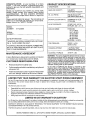
SPECIFICATIONS
HORSEPOWER:
12.5
GASOLINE CAPACITY:
5 QUARTS
UNLEADED REGULAR
OIL (3.0 PINTS):
SAE 30 (Above 32°F)
SAE 5W-30 (Below 32°F)
SPARK PLUG (GAP.030 IN.):
CHAMPION RJ-19LM
STD361458
VALVE CLEARANCE:
INTAKE .005 - .007 IN.
EXHAUST .009 - .011 IN.
GROUND SPEED:
FORWARD
1st 1.10 MPH
2nd 1.40 MPH
3rd 2.00 MPH
4th 3.00 MPH
5th 4.20 MPH
6th 5.0O MPH
REVERSE: 1.50 MPH
TIRE PRESSURE:
FRONT: 14 PSI
REAR: 10 PSI
CHARGING SYSTEM:
3 AMPS BATTERY
5 AMPS HEADLIGHTS
BLADE BOLT TORQUE:
30-35 FT. LBS.
SERIAL
NUMBER
DATE OF PU RCHAS E
THE MODELAND SERIAL NUMBERS WILL BE FOUND
ON A PLATE UNDER THE SEAT.
YOU SHOULD RECORD BOTH SERIAL NUMBERAND
DATE OF PURCHASE AND KEEP IN A SAFE PLACE
FOR FUTURE REFERENCE.
MAINTENANCE
AGREEMENT
WARNING: This unit is equipped with an internal combustion engine and should not be used on or near any unimproved forest-covered r brush-covered or grass-covered
land unless the engine s exhaust system is equipped with
a spark arrester meeting appligable local or state laws {if
a_ny). If a spark arrester Is used, it should be maintained m
effective working order by the operator.
A Sears Maintenance Agreement is available on this product. Contact your nearest Sears store for details.
CUSTOMER
RESPONSIBILITIES
•
Read and observe the safety rules.
•
Follow a regular schedule in maintaining, caring for and
using your unit.
•
Follow the instructions under "Customer Responsibilities" and "Storage" sections of this owner's manual.
In the state of California the above is required by law
(_Section 4442 of the California Public Resources Code).
Other states may have similar laws. Federal laws apply on
federal lands. A spark arrester for the muffler is available
through your nearest Sears Authorized Service Center
(See REPAIR PARTS section of this manual).
®
LIMITED TWO YEAR WARRANTY
ON ELECTRIC
START RIDING EQUIPMENT
For two (2) years from the date of purchase, if this ridingequipment is maintained, Lubricatedand tuned up according to the
instructions in the owner's manual, Sears will repair or replace, free of charge, any parts found to be defective in material or
workmanship.
This Warranty does not cover:
•
•
•
Expendable items which become worn during normal use, such as blades, spark plugs, air cleaners and belts.
Tire replacement or repair caused by puncturesfrom outside objects, such as nails, thorns, stumps, or glass.
Repairs necessary because of operator abuse, negligence, improper storage or accident or the failure to maintainthe
equipment according to the instructions contained Jnthe owner's manual.
Riding equipment used for commercial or rental purposes.
LIMITED 90 DAY WARRANTY
ON BATTERY
For 90 daysfrom date of purchase, if any battery included with this riding equipment proves defective in material or workmanship
and our _estingdeter:r0inesthe battery will not hold a charge, Sears will replace the battery at no charge....
WARRANTY SERVICE IS AVAILABLE BY RETURNING THE RIDING EQUIPMENT TO THE NEAREST SEARS SERVICE
CENTER/DEPARTMENT IN THE UNITED STATES.
This Warranty gives you specific legal rights, and you may also have other rights which may vary from state to state.
SEARS, ROEBUCK AND CO., D/731CR-W, SEARS TOWER, CHICAGO, ILLINOIS 60684
3
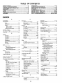
TABLE OF CONTENTS
SAFETY RULES ............................................................
2
PRODUCT SPECIFICATIONS ....................................... 3
CUSTOMER RESPONSIBILITIES ..................... 3, 15-18
WARRANTY ...................................................................
3
TABLE OF CONTENTS .................................................
4
INDEX .............................................................................
4
TRACTOR ACCESSORIES ........................................... 5
ASSEMBLY ..............................................................
7-10
OPERATION ...........................................................
11-14
MAINTENANCE SCHEDULE ...................................... 15
SERVICE AND ADJUSTMENTS ............................ 19-24
STORAGE ....................................................................
25
TROUBLESHOOTING ............................................
26-27
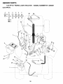
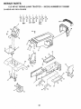
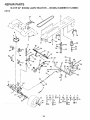
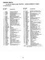
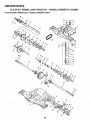
REPAIR PARTS - TRACTOR ................................. 30-45
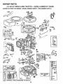
REPAIR PARTS - ENGINE ..................................... 46-50
PARTS ORDERING/SERVICE ................... BACK PAGE
INDEX
A
Accessories ............................................
Adjustments:
Brake ...........................................
Carb ureto r ........................... ........
Mower
Front-To-Back ........................
Side-To-Side ..........................
Throttle Control Cable .................
5
21
24
20
20
24
Air Filter, Engine ................................. 18
Air Screen, Engine .............................. 18
Assembly .........................................
7-10
B
Battery:
Charging ........................................
8
Cleaning ......................................
17
Installation ..................................... 9
Levels .......................................
8,17
Preparation .................................... 8
Starting with Weak Battery .......... 22
Storage ........................................
25
Terminals .................................... 17
Belt:
Motion Drive
RemoVaVReplacement ........... 21
Mower Blade Drive
RemovaVReplacement
........... 21
Blade:
Sharpening ..................................
Replacement ...............................
Brake Adjustment ...............................
16
16
21
C
Carburetor Adjustment ....................... 24
Controls, Tractor ................................. 11
Customer Responsibilities ............. 15-18
Engine:
Air Filter ...................................
18
Air Filter Foam Pre-C]eaner .... 18
Air Screen, Engine .................. 18
Battery ...................................... 17
Cooling Fins, Engine ............... 18
Engine Oit ................................ 17
Fuel Filter ................................ 18
Spark Plugs ............................. 18
Tractor:
......................
Blade .......................................
16
Lubrication Chart ..................... 15
Maintenance Schedule ............ 15
Tire Care ......................... 8,16,22
Cutting Height, Mower ........................ 12
E
Electrical:
Interlocks and Relays .................. 23
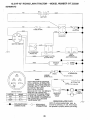
Schematic ................................... 29
Wiring Diagram ............................ 30
Engine:
Air Filter ....................................... 18
Air Filter Foam Pre-Cleaner ........ 18
A r Screen ................................... 18
Cooling Fins, Engine ................... 18
Oil Change .................................. 17
Oil Level ................................. 13,17
Oil Type ....................................... 17
Preparation .................................. 13
Repair Parts ........................... 46-50
Starting ........................................
14
Operation .......................................
11-14
Operating Mower ...:............................ 13
Options:
Accessories .;................................. 5
Spark Arrester .......................... 3,40
P
Parking Brake ................................ 11-12
Parts Bag ..............................................
6
Parts, Replacement/Repair
........... 30-45
Product Specifications ........................... 3
R
Repair Parts ..................................
S
30-45
Storage ........................................
25
F
Filter:
Air Filter .......................................
18
Air Filter Foam Pre-Cleaner ........ 18
Fuel .............................................
18
Safety Rules .......................................... 2
Seat ......................................................
8
Service and Adjustments ............... 19-24
Carburetor ........................... ;....... 24
Fuse ............................................
23
Hood Removal/Installation.,
........ 23
Motion Drive Belt
Fuel:
Type ............................................
Storage ........................................
Fuse ....................................................
H
Hood RemovaVInstallation ..................
L
Leveling Mower Deck .........................
Lubrication:
Chart ...........................................
M
Maintenance Schedule .......................
Mower:
Remova!/Replacement
........... 21
Mower Blade Drive Belt
Removal/Replacement
........... 21
Mower Adjustment
Front- to-Back ......................... 20
Side-to-Side ............................ 20
Mower Removal .......................... 19
Tire Care ............................. 8,16,22
Slope Guide Sheet ............................. 51
Spark Plugs ........................................
18
Specifications .......................................
3
Starting the Engine ........................ 13-14
Steering Wheel ....... ......................... 7,22
13
25
23
23
20
15
15
Adjustment, Front-to-Back ...........
Adjustment, Side-to-Side ............
Blade Sharpening ........................
Blade Replacement .....................
Cutting Height ..............................
Tnstallation...................................
20
20
16
16
12
19
Stopping the Tractor ........................... 12
Storage ...............................................
25
T
"l'hrottle Control Cable
Adjustment .................................. 24
Tires ............................................ ,....8,16,22
Operation ....................................
Removal ......................................
13
19
Trouble Shooting Chart .................. 26-27
Mowing Tips .......................................
14
Transaxle:
Muffler ================================================
18
Repair Parts ......................... ,.,..44-45
Spark Arrester ..........................
Mulcher Plate ...............................
3,40
10
O
Oil:
Cold Weather Conditions ....... 13,17
Engine ......................................... 17
Storage ........................................ 25
4
W
Warranty ...............................................
Wiring Diagram ...................................
Wiring Schematic ................................
3
30
29
ACCESSORIES
AND ATTACHMENTS
These accessories and attachments were available when the tractor was purchased. They are also available at most Sears retail outlets,
catalog and service centers. Most Sears stores can order these items for you when you provide the model number of your tractor.
ENGINE
SPARK PLUG
MAINTENANCE
MUFFLER
AIR RLTER
GAS CAN
ENGINE OIL
STABILIZER
BLADES
BELTS
PERFORMANCE
Sears offers a wide variety of attachments that fit your tractor. Many of these are listed below with brief explanations of how they can help
you. This list was current at the time of publication; however, it may change in future years - more attachments may be added, changes
may be made in these attachments, or some may no longer be available or fit your model. Contact your nearest Sears store for the
accessories and attachments that are available for your tractor.
Most of these attachments do not require additional hitches or conversion kits (these that do are indicated) and are designed for easy
attaching and detaching.
PERMANEX
BAGGER lets you collect grass clippings and
leaves for a healthier, nearer looking lawn. Two Permane×
containers hold 30-gallon plastic bags.
LAWN SWEEPERS
SNOW BLADE for snow removal only. 14-inch high, 42-inch
wide blade clears 38-inch path when angled left or right. Raises,
lowers with side lever. Adjustable skids; replaceable, reversible
scraper bar. (Use with tire chains, wheel weights, or rear drawbar
weight.)
let you collect grass clippings and leaves.
LAWN VAGS for powerful collection of heavy grass clippings and
leaves. Wand attachment to pick up debris in hard-to-reach
places.
SNOWTHROWER has40-inch swatl_. Drum-typeauger
handles
powdery and wet/heavy snow. Mounts easily with simple pin
arrangement. Discharge chute adjusts from tractor seat. 6-inch
diameter spout discharges snow 10 to 50 feet. Lift controlled at
tractor seat. (Use with chains, wheel weights, or rear drawbar
weight.)
CARTS make hauling easy. Variety of sizes available.
ROLLER for smoother lawn surface.
36-inch wide, 18-inch
diameter water-tight drum holds up to 390 Ibs. of weight. Rounded
edges prevent harm to tuff. Adjustable scraper automatically
cleans drum.
TIRE CHAINS are heavy duty; closely sp_ced extra-large
links give smooth ride, outstanding traction.
SPREADER/SEEDERS
make seeding, fertilizing, and weed
killing easy. Broadcast spreaders are also useful for granular
de-icers and sand.
cross
WHEEL WEIGHTS for rear wheels provide needed traction for
snow removal or dozing heavy materials. In pairs. (30 Ibs. each.)
TRACTOR CAB has heavy duty vinyl fabric over tubular steel
frame, ABS plastic top; clear plastic windshield offers 360 degree
visibility. Hinged metal doors with catch. Keeps operator warm
and dry. Remove vinyl and windshields for use as sun protector
in summer: (Catalog only.)
CORING AERATOR takes small plugs out of soil to al!ow moisture and nutrients to reach grass roots. 36-inch swath. 24
hardened steel coring tips. 150 lb. capacity weight tray.
AERATOR promotes deep root growth for a healthy lawn. Tapered 2.5-inch steel spikes mounted on 10-inch diameter discs
puncture holes in soil at close intervals to let moisture soak in.
Steel weight tray for increased penetration.
Optional accessories for tractor cab: tinted/tempered
solid
safety glass windshield with hand operated wiper; 12-volt amber
caution light for mounting on cab top. (Catalog only.)
MULCH RAKE/DETHATCHER
loosens soil and flips thatch and
matted leaves to lawn surface for easy pickup. Twenty spring tine
teeth. Usefultopreparebareareasforseeding.
Availableforfront
or rear mounting.
TRACTOR COVER protects tractor from weather.
Made of
Evolution 3 fabric (water-repellent, extremely breathable, light
weight, soft, non-abrasive, pliable in all temperatures, durable,
stainfteadpuncture resistant, will not shrink or stretch.) (Catalog
only.)
SPRAYERS use 12wolt DC electric motor that connects to the
tractor battery or other 12-volt source.
Includes booms for
automatic spraying when put{ing, and hand held wand for spot
spraying.
Wand has adjustable spray pattern. For applying
herbicides, insecticides, fungicides, and liquid fertilizers.
TILLER has 5 hp engine and 36-inch swath to prepare seed beds,
cultivate, and compost garden residue. Tiller has its own built-in
lift and depth control system and does NOT require a sleeve hitch.
Fits any lawn, yard, or garden tractor. Simply hook up to the
tractor drawbar and go!
5
CONTENTS
Parts Bag contents
OF HARDWARE
shown full size
PACK
Parts packed
separately
in carton
O
(2) Sheet
Metal
Seat
Screws
#10-16 x 1/2
Battery acid
Plate
(1) Locknut 3/8-24
(1) 2-3/8" Diameter Washer
IF-
Mulcher
'l
I I'
Steering
Wheel
Battery
"
!
!
!
I
(1) Shoulder Bolt 5/16-18
Steering
Boot
(1) Hex Bolt 1/2-13 x 1
I
I
!
I
Owner's Manual
Parts Bag
m
(1) Lock Washer 1/2
(1) Washer
Parts bag contents
not shown
full size
17/32 x 1-3/16x 12 Gauge
,
(2) Screws
#10 x 5/8
(2) Lock Washers
#10
(2) Washers
Steering Wheel
Adapter
Steering
Bushing
(2) Weld Nuts #10
Wheel
Insert
(2) Latch Hook
Assemblys
(2) Keys
3/16 x 3/4 x 16 Gauge
-//
(2) Hex Bolts !/4-20 x 3/4
![
_-
i
i
.........
_
........
i
(2) Hex_._NutS1/4-20
i
-i
J,
\
(2) Washers 9/32 x 5/8 x 16 Gauge
(2) Lock Washers
1/4
15 = Slope Sheet
Battery Caps
and Instructions
ASSEMBLY
Your new tractor has been assembled at the factory with exception of those parts left unassembled for shipping purposes.
To ensure safe and proper operation of your tractor all parts and hardware you assemble must be tightened securely. Use
the correct tools as necessary to insure their proper tightness,
TOOLS
REQUIRED
FOR ASSEMBLY
A socket wrench set will make assembly easier, Standard
wrench sizes are listed.
(1) 5/16" wrench
Tire pressure gauge
(2) 7/16" wrenches
Phillips Screwdriver
(1) 1/2" wrench
Utility knife
_._
INSERT
....._
3/8-24 HEX LOCKNUT
_
2-3/8 DIA. WASHER
(1) 9/16" wrench
(1) 3/4" wrench
STEERING
Sw g;dNG
When right and left hand is mentioned in this manual, it
means when you are in the operating position (seated
behind the steering wheel).
ADAPTER
STEERING
TO REMOVE
@
STEERING
UNIT FROM CARTON
UNPACK CARTON
Remove all accessible loose parts and parts cartons
from carton (See page 6).
Cut along dotted lines on carton, from top to bottom, all
four corners of carton and lay panels flat.
.
STEERING
_HAFT
" TAB
HOLE
Check for any additional loose parts or cartons and
remove.
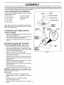
BEFORE
ATTACH
ROLLING
STEERING
UNIT OFF SKID
WHEEL
(See Fig. 1)
•
Slide the steering bushing over the steering shaft.
•
Raise steering shaft forward until screw holes in dash
line up with steering bushing, Install two (2) sheet
metal screws and tighten securely.
•
Position steering boot over steering shaft.
•
Align tabs of steering boot over slots and hole in dash
and push down to secure.
•
Slide steering wheel adapter onto upper steering shaft.
Position front wheels of the tractor so they are pointing
straight forward.
Position steering wheel so cross bars are horizontal
(left to right) and slide onto adapter.
•
Assemble large flat washer and 3/8-24 hex Iocknut and
tighten securely.
•
Snap insert into center of steering wheel.
Remove protective plastic from tractor hood and grill,
IMPORTANT:
CHECK
FOR AND REMOVE
ANY
STAPLES iN SKID THAT MAY PUNCTURETIRES WHERE
UNIT IS TO ROLL OFF SKID,
(See Fig. 8)..............
•
Raise attachment lift lever to its highest position.
•
Release
pedal.
.
.
Place gearshift lever in "NEUTRAL" position.
Roll unit backwards off skid.
parking brake by depressing
clutch/brake
Remove banding holding discharge guard up against
tractor.
WHEEL
FIG. 1
SCREW
ASSEMBLY
HOW TO SET UP YOUR TRACTOR
INSTALL
PREPARE BATTERY (See Fig. 2)
Adjust seat before tightening adjustment bolt.
•
SEAT (See Fig. 3)
Remove cardboard packing on seat pan.
CAUTION: Wear eye and face shield.
•
Place seat on pan and assemble shoulder bolt.
Wash hands or clothing immediately if
accidentally in contactwith battery acid.
,
Assemble adjustment bolt, Iockwasherandflatwasher
loosely. Do not tighten.
°
Tighten shoulder bolt securely.
Do not acid
smoke.
Fumes from charged
battery
are explosive.
•
Lower seat into operating position and sit on seat.
Read the instructions included with the
battery vent caps. Always wear gloves,
clothing and goggles to protect your
hands, skin and eyes.
•
°
Slide seat until a comfortable position is reached which
allows you to press clutch!brake pedal all the way down
(See Fig. 8).
Get off seat without moving its adjusted position.
•
Raise seat and tighten adjustment bolt securely.
Your unit has a battery charging system which is sufficient
for normal use. However, periodic charging of the battery
with an automotive charger will extend its life.
®
See instructions packed with vent caps in parts bag.
,=
Fill battery with acid. Fill each cell until it reaches the
bottom of the vent wells. Do not overfill.
•
Allow battery to stand and settle for at least thirty
minutes. After standing, check the level of acid. If
below the vent wells, add more acid until the correct
level is reached.
SEAT
SEAT PAN
SHOULDER
BOLT
While battery is standing (after adding acid) and later, while
battery is being charged, continue with assembly of unit.
IMPORTANT:
TO MAXIMIZE THE LiFE OF YOUR
BATTERY, IT IS NECESSARY THAT THE BATTERY BE
CHARGED
BEFORE USE. FAILURE TO CHARGE
BATTERY CAN RESULT IN A SHORTENED BATTERY
LIFE.
o
ADJUSTMENT
BOLT
Charge battery at a rate of 6 amperes for 1 hour. Use
a 12 volt battery charger. Observe all safety precautions
required for battery charging.
o
Check the acid level after the battery is charged. If the
acid has fallen below the correct level, add distilled or
iron free water.
•
Install the vent caps to cover the vent wells. Wash the
top of the battery with water to remove any acid, then
wipe dry.
•
Check battery case for leakage to make sure that no
damage has occurred in handling.
•
FLATWASHER
FIG. 3
CHECK
CHECK DECK LEVELNESS
For best cutting,results, mower housing should be properly
leveled. See TO LEVEL MOWER HOUSING" in the
Service and Adjustments section of this manual.
CHECK
FOR
PROPER
POSITION
OF
ALL
BELTS
CUT AWAY VIEW
See the figures that are shown for replacing motion and
mower b ad_ drve belts n the Serv ce andAdjustments
section
of this manual. Verify that the belts are routed
correctly.
.....
CHECK
BATTERY
CELL ACID
LEVEL
FIG. 2
PRESSURE
Reduce tirepressure
to PSI shown in "PRODUCT
SPECIFICATIONS" on page 3 of this manual.
on how to install battery.
VENTWELL
TIRE
The tires on your unit were overinflated at the factory for
shipping purposes. Correct tire pressure is important for
best cutting performance.
Dispose of excess battery acid. Neutralize
acid for
disposal by adding it to four inches of water in a five
gallon plastic container. Stir with a wooden or plastic
paddle while adding baking soda until the addition of
more soda causes no more foaming.
Follow instructions
LOCK WASHER
8
BRAKE
SYSTEM
After you learn how to operate your tractor, check to see
that the brake is properly adjusted. See "TO ADJUST
BRAKE" in the Service and Adjustments section of this
manual.
ASSEMBLY
INSTALL
BATTERY
(See Figs. 4 & 5)
CAUTION: Do not short battery termF
rials. Before installing battery, remove
rings, etc.
metal bracelets,
wristwatch
bands,
Positive terminal must be connected
first to prevent sparking from accidental grounding.
Lift seat to raised position.
•
Open battery box door.
•
Lower battery into battery box with battery terminals
toward front of unit.
BATTERY
BOX DOO_
Be sure battery drain tube is attached to battery box.
First connect RED battery cable to positive (+) battery
terminal with hex bolt, flat washer, lock washer and hex
nut as shown. Tighten securely.
.
•
Connect BLACK grounding cable to negative (-) battery terminal with remaining hex bolt, flat washer, lock
washer and hex nut. Tighten securely.
Close battery box door.
VENT CAPS
FIG. 5
Open battery box door for:
Inspection for secure connections
ware).
(to tighten hard-
Inspection for corrosion.
•
Testing battery.
•
Jumping (if required).
•
Periodic charging.
BATTERY
BOX DOOR
POSITIVE
NEGATIVE
(RED) CABLE
(BLACK)
CABLE
HF_X
BOLT
POSITIVE (+) TERMINAL
NEGATIVE (-) TERMINAL
FiG. 4
9
ASSEMBLY
INSTALL
MULCHER
PLATE
TO CONVERT TO BAGGING
(See Figs. 6 & 7)
OR DISCHARGING
Simply remove mulcher plate and store in a safe place.
Your mower is now ready for discharging or installation of
optional grass catcher accessory.
Install two latch hooks, to mulcher plate using screw,
...... 4_a..s_er, lock washer, and weld nut as shown.
NOTE: Pre-assemble weld nut to latch hook by inserting weld nut from the top with hook pointing down.
,/CHECKLIST
Tighten hardware securely.
•
Raise and hold deflector shield in upright position.
,
•
Place front of mulcher plate over front of mower deck
opening and slide into place, as shown.
Hook front latch into hole on front of mower deck.
BEFORE YOU OPERATE AND ENJOY YOUR NEW
TRACTOR, WE WISH TO ASSURE THAT YOU RECEIVE
THE BEST PERFORMANCE AND SA TISFACTION FROM
THIS QUALITY PRODUCT.
,
Hook rear latch into hole on back of mower deck.
PLEASE REVIEW THE FOLLOWING CHECKLIST:
CAUTION: Do not remove diseharg_
from mower. Raise and hold guard when I
attaching mulcher plate and allow it to J
rest on plate while in operation.
J
WELD NUT
/
\\\
FROM THE TOP _/F
WELD
HOOK POINTS
DOWN
LOCK
NUTWASHERsCREW
\"
LATCH
HOOK
,/
All assembly instructions have been completed.
,/
No remaining loose parts in carton.
,/
Battery is properly prepared and charged.
1 hour at 6 amps).
,,"
Seat is adjusted comfortably and tightened securely.
¢'
Al! tires are properly inflated. (For shipping purposes,
the tires were overinflated at the factory).
,,/
Be sure mower deck is properly leveled side-to-side/
front-to-rear for best cutting results. 0-ires must be
properly inflated for leveling).
¢'
Check mower and drive belts. Be sure they are routed
properly around pulleys and inside all belt keepers.
¢"
Check wiring. See that all connections are still secure
and wires are properly clamped.
HOOK
LOCK
WHILE LEARNING HOWTO USE YOUR TRACTOR, PAY
EXTRA A TTENTION TO THE FOLLOWING IMPORTANT
ITEMS:
/
WASHER
WASHER
',
MULCHER
PLATE
WASHER
\
WELD
NUT
_""_SCREW
¢'
Engine oil is at proper level.
¢'
Fuel tank is filled with fresh, clean, regular unleaded
gasoline.
Become familiar with all controls - their location and
function. Operate them before you start the engine.
,/
FIG. 6
v"
DEFLECTOR
SHIELD
LATCH
HOOKS
f
IMinimum
FIG. 7
10
Be sure brake system is in safe operating condition.
0
KNOW YOUR TRACTOR
READ
THIS
OWNER'S
MANUAL
AND
SAFETY
RULES
BEFORE
OPERATING
YOUR
TRACTOR
Comparethe illustrationswith your tractor to familiarize yourself with the locations ofvarious controls and adjustments. Save
this manual for future reference.
UFTLEVER
PLUNGER
ATTACHMENT
CLUTCH LEVER
ATTACHMENT
LIFr LEVER
LIGHT SWITCH
CONTROL
MOWER DECK
HEIGHT ADJUSTMENT
POSfflONS
CLUTCH/BRAKE
PEDAL
[
]
GEARSHIFT
LEVER
IGNITION
SWITCH
FIG. 8
Sears tractors conform to the safety standards of the American National Standards Institute.
ATTACHMENT CLUTCH LEVER: Used to engage the
mower blades, or other attachments mounted to your
tractor.
GEARSHIFT LEVER: Selects the speed and direction of
tractor.
ATTACHMENT LIFT LEVER: Used to raise, lower, and
adjust the mower deck or other attachments mounted to
your tractor.
LIFT LEVER PLUNGER: Used to release attachment lift
lever when changing its position.
LIGHT SWITCH: Turns the headlights on and off.
THROTTLE!CHOKE
CONTROL: Used for starting and
controlling engine speed.
CLUTCH!BRAKE
PEDAL:
Used for declutching and
braking the tractor and starting the engine.
PARKING BRAKE:
brake position.
Locks clutch/brake
IGNITION SWITCH:
engine.
pedal into the
11
Used for starting and stopping the
OPERATION
The operation of any tractor can result in foreign objects thrown into the eyes, which can
result in severe eye damage. Always wear safety glasses or eye shields while operating
your tractor or performing any adjustments or repairs. We recommend wide vision safety
mask for over the spectacles or standard safety glasses, available at Sears Retail or
Catalog stores.
HOW TO USE YOUR TRACTOR
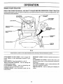
TO SET PARKING
•
BRAKE
NOTE: Under certain conditions when unit is standing idle
with the engine running, hot engine exhaust gases may
cause "browning" of grass. To eliminate this possibility,
always stop engine when stopping unit on grass areas.
(See Fig. 9)
Depress clutch!brake pedal into full "BRAKE" position
and hold.
CAUTION: Always stop unit completely,
as described above, before leaving the
operator's
position; to empty grass
catcher, etc.
Place parking brake lever in "ENGAGED" position and
release pressure from clutch/brake pedal. Pedal should
remain in "BRAKE" position. Make sure parking brake
will hold vehicle secure.
"DISENGAGED'
POSITION
ATTACHMENT
CLUTCH LEVER
"ENGAGED"
POSITION
•
TO USE THROTTLE
CONTROL
(See Fig. 9)
Always operate engine at full throttle.
PARKING
BRAKE
"ENGAGED'
POSITION
•
Operating engine at less than full throttle reduces the
battery charging rate.
•
Full throttle offers the best bagging and mower performance.
IGNITION
KEY
TO MOVE FORWARD
Fig. 9)
THROTTLF.J
CHOKE
CONTROL.
LEVER
AND BACKWARD
(See
The direction and speed of movement is controlled by the
gearshift lever.
•
Start tractor with clutch!brake pedal depressed and
gearshift lever in "NEUTRAL" position.
Move gearshift lever to desired position.
GEARSHIFT
LEVER
•
Slowly release clutch/brake pedal to start movement.
iMPORTANT: BRING TRACTOR TO A COMPLETE STOP
BEFORE SHIFTING OR CHANGING GEARS. FAILURE
TO DO SO WILL SHORTEN I'HE USEFUL LIFE OF YOUR
TRANSAXLE.
"BRAKE"
POSITION
CLUTCH/BRAKE
PEDAL "DRIVE = POSITION
PARKING BRAKE
"DISENGAGED" POSITION
TO ADJUST
Fig, 8)
FIG. 9
STOPPING
MOWER BLADES -
•
Move attachment clutch lever to "DISENGAGED"
sition.
po-
Depress clutch/brake pedal into full "BRAKE" position.
lever to "NEUTRAL" position.
......
lift lever determines the
Grasp lift lever.
For best cutting performance, grass over 6 inches in
height should be mowed twice. Make the first cut
relatively high; the second to desired height.
Turn ignition key to "OFF" position and remove key.
Always remove key when leaving vehicle to prevent
unauthorized use.
Never use choke to stop engine.
(See
The average lawn should be cut approximately 2-1/2 ......
inches during the cool season and over 3 inches during
hot months. For healthier and better looking lawns,
mow often and after moderate growth.
NOTE: Failure to move throttle control to "SLOW" position
and allowing engine to idle before stopping may cause
engine to "backfire".
;
HEIGHT
Press plunger with thumb and move lever to desired
position.
Thecutting height rangeis approximately 1-1/2to 4". The
heights are measured from the ground to the blade tip with
the engine not running. These heights are approximate
and may vary depending upon soil conditions, height of
grass and tyDes of grass being mowed.
GROUND DRIVE -
, .. Move throttle control to "SLOW" position.
CUTTING
The position of the attachment
cutting height.
(See Fig. 9)
Move gearshift
ENGINE -
MOWER
12
OPERATION
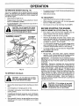
TO OPERATE
MOWER
(See Fig. 10)
Your unit is equipped with an operator presence sensing
switch. Any attempt by the operator to leave the seat with
the engine running and the attachment clutch engaged will
shut off the engine.
+
Select desired height of cut.
-
Engage mower by slowly moving attachment clutch
lever to "ENGAGED" position.
TO STOP MOWER - Move attachment clutch lever to
"DISENGAGED" position.
+
without either the entire grass catcher,
CAUTION:
Doequipped,
not operate
the mower
on mowers so
mulcher
plate,
or the discharge guard in place.
ATrACHMENTCLUTCHLEVER
"DISENGAGED"POSITION
"ENGAGED"
POSITION
A'I3"ACHMENT
LIFT LEVER
HIGH POSITION
•
To restart movement, slowly release parking brake and
clutch/brake pedal.
•
Make all tums slowly.
TO TRANSPORT
•
Raise attachment lift control to highest position.
+
When pushing or towing your unit, be sure gearshift
lever is in "NEUTRAL" position.
,
Do not push or tow unit at more than five (5) MPH.
BEFORE
CHECK
STARTING
THE ENGINE
ENGINE OIL LEVEL (See Fig. 16)
•
The engine in your unit has been shipped, from the
factory, already filled with summer weight oil.
•
Check engine oil with unit on level ground.
+
Remove oi! fill dipstick and wipe clean, replace and
screw cap tight, wait for a few seconds, remove and
read oil level. If necessary, add oil until "FULL" mark
on dipstick is reached. Do not overfill.
•
For cold weather operation you should change oil for
easier starting (see "OIL VISCOSITY CHART" in the
Customer Responsibilities section of this manual).
•
To change engine oil, see the Customer Responsibilities sectMon in this manual.
LOW
POSITION
ADD GASOLINE
+
Fill fuel tank. Use fresh, clean, regular unleaded
gasoline. (Use of leaded gasolinewill increase carbon
and lead oxide deposits and reduce valve life).
IMPORTANT:
WHEN OPERATING IN TEMPERATURES
BELOW 32° F(0°C), USE FRESH, CLEAN WINTER GRADE
GASOLINE TO HELP INSURE GOOD COLD WEATHER
STARTING.
FIG. 10
TO OPERATE
ON HILLS
hills with slopes greater than 15° and
CAUTION:
Do not drive up or down
do not drive across any slope.
WARNING:
Experience indicates that alcohol blended
fuels (called gasohol or using ethanol or methanol) can
attract moisture which leads to separation and formation of
acids during storage. Acidic gas can damage the fuel
system of an engine while in storage. To avoid engine
problems, the fuel system should be emptied before storage of 30 days or longer. Drain the gas tank, start the
engine and let it run until the fuel lines and carburetor are
empty_ Use fresh fuel next season. See Storage Instructions for additional information.
Never use engine or
carburetor cleaner products in the fuel tank or permanent
damage may occur.
•
Choose the slowest speed before starting up or down
hills_
filler neck. Do not overfill. Wipe off any
CAUTION:
spilled
oil orFill
fuel.to Do
bottom
not store,
of gas
spill
tank
or
+
Avoid stopping or changing speed on hills,
use gasoline near an open flame.
,
If slowing is necessary,
slower position.
°
if stopping is absolutely necessary, push clutch/brake
pedal quickly to brake position and engage parking
brake.
•
Move gearshift lever to 1st gear and be sure you have
allowed room for tractor to roll slightly as you restart
movement.
move throttle control lever to
.....................
!3 ¸
OPERATION
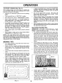
TO START ENGINE (See Fig. 9)
•
When starting engine for the first time or if engine has
run out of fuel, it will take extra cranking time to move
fuel from the tank to the engine.
•
Depress the clutch/brake
brake.
-
Place gearshift lever in "NEUTRAL"
•
Move attachment clutch to "DISENGAGED" position.
-
Move throttle control lever to "CHOKE" position for
cold engine start.
For warm engine start, move
throttle control to "FAST" position.
•
•
Do not mow grass when it is wet.
plug mower and leave undesirable
grass to dry before mowing.
pedal and set the parking
position:
When operating attachments, select a ground speed
that will suit the terrain and give best performance of
the attachment being used.
MULCHING
NOTE: If at a high altitude (above 3000 feet) or in cold
temperatures (below 32 ° F), the carburetor fuel mixture
may need to be adjusted for best engine performance.
See "TO ADJUST CARBURETOR" in the Service and
Adjustments section of this manual.
TIPS
Tire chains cannot be used when the mower ho(Jsing is attached to unit.
Mower should be properly leveled for best mowing
performance. See "TO LEVEL MOWER HOUSING"
m the Service and Adjustments
section of this
manual.
The left hand side of mower should be used for trimming.
-
Drive so that clippings are discharged onto the area
that has been cut. Have the cut area to the right of
the machine. This will result in a more even distribution of clippings and more uniform cutting.
•
MOWING
TIPS
IMPORTANT:
FOR BEST PERFORMANCE,
KEEP
MOWER HOUSING FREE OF BUILT-UP GRASS AND
TRASH. CLEAN AFTER EACH USE.
The special mulching blade will recut the grass clippings many times and reduce them in size so that as
they fall onto the lawn they will disperse into the grass
and not be noticed. Also, the mulched grass will
biodegrade quickly to provide nutrients for the lawn.
Always mulch with your highest engine (blade) speed
as this will provide the best recurring action of the
blades.
When engine starts, move throttle control to desired
position.
Allow engine to warm up for a few minutes before
engaging drive or attachment clutch.
•
Wet grass will
clumps. Allow
Always operate engine at full throttle when mowing
to assure better mowing performance and proper
discharge of material.
Regulate ground speed by
selecting a low enough gear to give the mower
cutting performance as well as the quality of cut
desired.
Tum ignition key clockwise to "START" position and
release key as soon as engine starts. Do not run
starter continuously for more than fifteen seconds
per minute. If engine does not start after several
attempts, move throttle control to "FAST" position,
wait a few minutes and try again.
MOWING
If grass is extremely tall, it should be mowed twice
to reduce load and possible fire hazard from dried
clippings. Make first cut relatively high; the second
to the desired height.
-
Avoid Cutting your lawn when it is wet. Wet grass
tends to form clumps and interferes with the mulching
action. The best time to mow your lawn is the early
afternoon. At this time the grass has dried and the
newly cut area will not be exposed to the direct sun.
For best results, adjust the mower cutting height so
that the mower cuts off only the top one-third of the
grass blades (See Fig. 12). For extremely heavy
mulching, reduce your width of cut and mow slowly.
MAX 1/3-
When mowing large areas, start by turning to the
right so that clippings will discharge away from
shrubs, fences, driveways, etc. After one or two
rounds, mow in the opposite direction making left
hand turns until finished(See
Fig. 11).
FIG. 12
•
Certain types of grass and grass conditions may ....
....require that an-a.rea be muich_ a second time- to
completely hide the clippings. When doing a second
cut, mow across or perpendicular to the first cut path.
•
Change you r cutting pattern from week to week: Mow
north to south one week then change to east to west
the next week, This will help prevent matting and
graining of the lawn.
FIG. 11
14
m
CUSTOMER
RESPONSIBILITIES
,
T
Check Brake Operation
V _
If
Check Tire Pressure
V _
if
Check for LooseFasteners
Sharpen/Replace Mower Blades
v'
,,
,
_##'4
LubricationChart
!_ #_
T
Check Battery Level/Recharge
0
Clean Batteryand Terminals
t/
if
IV _
V s
F:_ Check Transmission Cooling
Adjust Blade Belt(s) Tension
_/'s
Adjust Motion Drive Belt(s) Tension
_##s
Check Engine Oil
Level
Change EngineOil
E
Clean
N
Clean Air Screen
G
Inspect
I
rN
if
_##
_
t_t_,3
Air Filter
Muffler/Spark
t_#'_
_2
__
Arrestor
Replace Oil Filter (If equipped)
V_,2
Clean EngineCooling Fins
Replace Spark Plug
_'2
if
ReplaceAir FilterPaper Cartridge
_2
Replace Fuel Filier
_
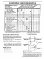
1 - Change more often when operating under a heavy load or In high ambient temperatures.
2 - Service more often when operating In dirty or dusty Conditions.
GENERAL
I
3 _ If equipped with oil filter, change otl every 50 hours.
4 - Replace blades more often when mowing in sandy soil.
5 - If equipped with adjustable system,
LUBRICATION
RECOMMENDATIONS
CHART
The warranty on this tractor does not cover items that have
been subjected to operator abuse or neg[igence.
To
receive full varue from the warranty, operator must maintain
tractor as instructed in this manual.
(_
Some adjustments will need tO be made periodically to
properly maintain your tractor.
BEARING
- FRONT WH EEL (_)
BEARING ZERK
ZERK
All adjustments in the Service and Adjustments section of
this manual should be checked at least once each season.
•
Once a year you should replace the spark plug, clean
or replace air filter, and check blades and belts for
wear. A new spark plug and clean air filter assure
proper air-fuel mixture and help your engine run better
and last longer.
BEFORE
EACH
(_ ATTACHM
CLUTCH
PIVOT(S)
EN'
USE
•
Check engine oil level.
•
Check brake operation ....
•
•
Check tire pressure.
Check for loose fasteners.
PIVOTS
(_) SAE 30 OR lOW30 MOTOR OiL API - SG
(_)GENERAL
(_REFER
15
PURPOSE GREASE
TO CUSTOMER
RESPONSIBILITIES
"ENGINE"
SECTION
IMPORTANT:
DO NOT OILER
GREASE THE PIVOT POINTS
WHICH HAVE SPECIAL NYLON BEARINGS,
VISCOUS LUBRICANTS WILL ATTRACT
DUST AND DIRTTHAT
WILL SHORTEN
THE LIFE OF THE SELF-LUBRICATING
BEARINGS.
IF YOU
FEEL THEY MUST BE LUBRICATED,
USE ONLY A DRY, POWDERED GRAPHITE
TYPE LUBRICANT
SPARINGLY.
CUSTOMER
RESPONSIBILITIES
TRACTOR
Always observe safety rules when performing any maintenance.
BRAKE
OPERATION
If unit requires more than six (6) feet stopping distance at
high speed in highest gear, than brake must be adjusted.
(See "TO ADJUST BRAKE" in Service and Adjustments
section of this manual).
TIRES
•
Maintain proper air pressure in all tires (See "PRODUCT SPECIFICATIONS" on page 3 of this manual).
•
Keep tires free of gasoline, oil, or insect control chemicals which can harm rubber.
•
Avoid stumps, stones, deep ruts, sharp objects and
other hazards that may cause tire damage.
BLADE
F'ATWASHER
O,T O.ADEo "
*A GRADE 8 HEAT TREATED BOLT CAN BE
IDENTIFIED BY SIX LINES ON THE BOLT HEAD.
CARE
For best results mower blades must be kept sharp. The
blades can be sharpened with a file or on a grinding wheel.
We suggest they be sharpened or replaced after every 25
hours of mowing. Check blades more often if mowing in
sandy conditions.
•
FIG. 13
TO SHARPEN
Do not attempt to sharpen blades while they are on the
mower.
Replace bent or damaged blades.
BLADE
REMOVAL
(See Fig. 13)
-
Raise mower to highest position to allow access to
blades.
•
Remove hex bolt, Iockwasherand
blade.
o
Install new or resharpened blade with trailing edge up
towards deck as shown.
•
Reassemble hex bolt, lock washer and flat washer in
exact order as shown.
BLADE (See Fig. 14)
Care should be taken to keep the blade balanced. An
unbalanced blade will cause excessive vibration and eventual damage to mower and engine.
.
"['hebladecan be sharpened with a file or on a grinding
wheel. Do not attempt to sharpen while on the mower.
flat washer securing
•
To check blade barance, you will need a 5/8'_diameter
steel bolt, pin, or a cone balancer. (When usinga cone
balancer, follow the instructions supplied with balancer).
•
Slide blade on to an unthreaded portion of the steel bolt
or pin and hold the bolt or pin parallel with the ground.
If blade is balanced, it should remain in a horizontal
position. If either end of the blade moves downward,
sharpen the heavy end until the blade is balanced.
NOTE: Do not use a nail for balancing blade. The lobes of
the center hole may appear to be centered, but are not.
Tighten bolt securely (30-35 R. Lbs. torque).
IMPORTANT: BLADE BOLT IS GRADE 8 HEATTREATED.
CENTER HOLE
5/8" BOLT
ORPIN
........................
..BLADE
/
/
FIG. 14
16
CUSTOMER
BATI'ERY
RESPONSIBILITIES
ENGINE
(See Fig. 15)
Your unit has a battery charging system which is sufficient
for normal use. However, pedodic charging of the battery
with an automotive charger will extend it's life.
,
LUBRICATION
Only use high quality detergent oil rated with API service
classification SG. Select the oil s SAE viscosity grade
according to your expected operating temperature.
Acid solution level in each battery cell should be even
with bottoms of vent wells. Add only distilled or iron free
water if necessary. Do not overfill.
CUT AWAY VIEW
I
L------J
/VENT
I-----.J
,
,
_
I"
RECOMMENDED
oF .20 °
°C -29°
LEVEL
FIG. 15
•
•
0o
-18 °
32 o
0°
80 °
27_
100_
38 °
NOTE: Although multi-viscosity oils (5W30, 10W30 etc.)
improve starting in cold weather, these multi-viscosity oils
will result in increased oil consumption when used above
32°F. Check your engine oil level more frequently to avoid
possible engine damage from running low on oil.
Check the crankcase oil level before starting the engine
and after each eight (8) hours of continuous use. Tighten
oil fill cap/dipstick securely each time you check the oil
level.
TO CHANGE ENGINE OIL (See Fig. 16)
•
Be sure vehicle is on level surface.
Rinse the battery with plain water and dry.
Clean terminals and battery cable ends with wire brush
until bright:
Coat terminals with grease or petroleum jel[y.
Reinstali battery (See "INSTALL BATTERY" in the
Assembly section of this manual).
•
•
Oil will drain more freely when warm.
Catch oil in a suitable container.
•
Remove oil fill dipstick. Be careful not to allow dirt to
enter the engine when changing oil.
Remove drain plug.
After oil has drained completely, replace oil drain plug
and tighten securely.
Refill engine with oil through oil fill dipstick tube. Pour
slowly. Do not overfill. For approximate capacity see
Product Specifications on page 3 of this manual.
•
V-BELTS
Use gauge on oil fill dipstick for checking level. Besure
dipstick cap is tightened securely for accurate reading.
Keep oil at "FULL" line on dipstick.
Check V-belts for deterioration and wear after 1O0 hours
and replace if necessary. The belts are not adjustable.
Replace belts if they begin to slip from wear.
TRANSAXLE
60o
16°
Change the oil after the first two hours of operation and
every 25 hours thereafter or at least once a year if the
tractor is not used for 25 hours in one year.
Keep battery and terminals clean.
Keep battery bolts tight.
Keep vent caps tight and small vent holes in caps open.
Recharge at 6 amperes for ! hour.
CLEAN BATTERY AND TERMINALS -
Corrosion and dirt on the battery and terminals can cause
the battery to "leak" power.
•
Remove terminal guard.
•
Disconnect BLACK battery cable first then RED battery cable and remove battery from tractor.
•
Wash battery with solution of four tablespoons of
baking soda to one gallon of water. Be careful not to get
the soda solution into the cells.
•
GRADES
CAP
VENT
WELL
ELL,O,O
•
•
•
TO
SAE VISCOSITY
OIL FILL
CAP/DiPSTICK
COOLING
Keep transaxle free from build-up of dirt and chaff which
can restrict cooling.
OIL DRAIN
PLUG
RG. 16
17
CUSTOMER
RESPONSIBILITIES
AIR FILTER FOAM PRE-CLEANER (See Fig.
17)
Your engine will not run properly and may be damaged by
using a dirty air filter. Cleanthe foam pre-cleaner element
after every 25 hours of operation, more often if used in very
dusty, dirty conditions.
,
Remove knob and cover.
•
Remove cartridge nut and replace cartridge.
•
Reassemble and tighten securely.
NOTE: Do not attempt to clean or oil the paper cartridge.
Replace paper cartridge once a year or after every 100
hours of operation, more often if used in very dusty, dirty
conditions.
•
Wash foam pre-cleaner
•
Wrap foam pre-cleaner in cloth and squeeze dry.
•
Lightly coat foam pre-cleaner with clean engine oil.
Squeeze in towel to remove excess oi!. Do not saturate.
STARTER
HOUSING
in liquid detergent and water.
OIL FILL
DIPSTICK
LK
PLUG
ENGINE COOLING RNS
FIG. 18
•
Install foam pre-cleaner over paper cartridge.
MUFFLER
•
Reassemble cover and secure with knobs.
_nspect and replace corroded muffler and spark arrester (if
equipped) as it could create a fire hazard and/or damage.
COVER
KNOB
SPARK PLUGS
Replace spark plugs at the beginning of each mowing
season or after every 100 hours of use, whichever comes
first. Spark plug type and gap setting is shown in "PRODUCT SPECIFICATIONS" on page 3 of this manual.
IN-LINE FUEL FILTER
(See Fig. 19)
Fuelfilter should be replaced once each season. Iffuel filter
becomes clogged, obstructing fuel flow to carburetor, replacement is required.
•
With engine cool, remove filter and plug fuel line
sections.
,
•
FIG. 17
Place new fuel filter in position in fuel line.
Be sure there are no fuel line leaks and clamps are
properly positioned.
Immediately wipe up any spilled gasoline.
AIR SCREEN (See Fig. 18)
The engine air screen must be kept free of dirt and chaff to
prevent engine damage from overheating. Clean with a
wire brush or compressed air to remove dirt and stubborn
dried gum fibers.
ENGINE
COOLING
FINS (See Fig. 18)
Remove any dust, dirt or o11from engine cooling fins to
prevent engine damage from overheating.
•
Remove oil fill dipstick and cover opening to prevent
entry of dirt.
FUEL
FILTER
CLEANING
FIG. 19
IMPORTANT:
FOR BEST PERFORMANCE,
KEEP
MOWER HOUSING FREE OF BUILD-UP, GRASS AND
TRASH. CLEAN UNDERSIDE OF MOWER HOUSING
AFTER EACH USE.
Remove screws from blower housing arid !ift hous ng
off engine: ......................
".
C!esn engine, battery, seat, finish, etc. of all foreign
matter.
•
Remove the screws securing the starter housing and
lift housing off engine.
•
Keep finished surfaces and wheels free of ait gasoline,
oil, etc,
•
Use compressed air or stiff bristle brush to thoroughly
clean engine cooling fins.
=
Protect painted surfaces with automotive type wax.
•
To reassemble,
reverse above procedure.
We do not recommend using a garden hose to clean your
unit unless the electrical system, muffler, air filter and
carburetor are covered to keep water out. Water in engine
18 can result in a shortened engine life.
SERVICE AND ADJUSTMENTS
CAUTION:
i
®
BEFORE PERFORMING ANY SERVICE OR ADJUSTMENTS:
Place gearshift lever in "NEUTRAL" position.
Depress clutch/brake pedal fully and set parking brake.
Place attachment clutch in "DISENGAGED" position.
Turn ignition key "OFF" and remove key.
Make sure the blades and all moving parts have completely stopped.
Discon nect spark plug wire from spark plug and place wire where it cannot come in contact with
plug.
TRACTOR
SEE NOTE ABOVE
CORRECT
TRUNNION
POSI_IIOfl
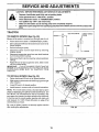
TO REMOVE MOWER (See Fig. 20)
Mower will be easier to remove from the right side of unit.
•
•
Place attachment clutch in "DISENGAGED" position.
Move attachment lift lever forwardto lower mower to its
lowest position.
•
Roll belt off engine pulley.
•
Disconnect clutch rod from clutch lever by removing
retainer spring.
•
Disconnect suspension arms from rear deck brackets
by removing retainer springs.
•
Disconnect front links from deck by removing retainer
springs.
W/i, I
CLUTCH
ROD
Raise lift lever to raise suspension arms. Slide mower
out from under tractor.
IMPORTANT:
IF AN ATTACHMENT OTHER THAN THE
MOWER IS TO BE MOUNTED TO THE TRACTOR, BOTH
SUSPENSION
ARMS MUST BE REMOVED FROM
TRACTOR.
CLUTCH LEVER
RETAINER
SPRING
•
SUSPENSION
ARMS
TO INSTALL MOWER (See Fig. 20)
•
Raise attachment lift lever to its highest position.
•
Slide mower under tractor with discharge guardto right
side of tractor.
•
•
Lower lift lever to its lowest position.
Install mower in reverse order of removal instructions.
NO'rE: The mower clutch rod has a trunnionthat has been
preset, at the factory, for optimum mower performance. DO
NOTMOVETHETRUNNIONONTHECLUTCH
ROD. Iffor
any reason the trunnion has been moved on the clutch rod,
it must be reset to correct position (parallel with clutch rod)
and measure 10-11/32" (Check dimension on edge of flat
work surface as shown).
RETAINER
SPRINGS
(bothsid_)
Be sure to tighten trunnion nut securely against trunnion
after making any adjustments.
FIG. 20
19
SERVICE AND ADJUSTMENTS
TO LEVEL MOWER
HOUSING
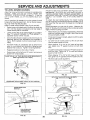
FRONT-TO-BACK ADJUSTMENT (See Figs. 23 and 24) IMPORTANT: DECK MUST BE LEVEL SIDE-TO-SIDE. IF
THE FOLLOWENG FRONT-TO-BACK ADJUSTMENT IS
NECESSARY, BE SURE TO ADJUST BOTH FRONT LINKS
EQUALLY SO MOWER WILL STAY LEVEL SIDE-TOSIDE.
To obtain the best cutting results, the mower housing
should be ad usted so that the front is approximately 1/4" to
3/4" lower than the rear when the mower s n its highest
position.
Check adjustment on right side of tractor. Measure distance "D" directly in front and behind the mandrel at bottom
edge of mower housing as shown.
Adjust the mower while tractor is parked on level ground or
driveway.
Make sure tires are properly inflated (See
"PRODUCT SPECIFICATIONS" on page 3). If tires are
over or under inflated, you will not properly adiust your
mower.
You will need two (2) standard 2 x 4 short pieces of wood
to make the following adjustment. Simi!ar blocks measuring 1-1/2" thick may also be used.
SIDE-TO-SIDE ADJUSTMENT (See Figs.21 and 22) •
Raise mower with attachment lift control to allow two
(2) 1-1/2" thick blocks to be placed under rear edge of
mower directly behind mandrels.
•
Lower mower deck to its lowest height of cut position
(See 'q-O ADJUST MOWER CUTTING HEIGHT" in
Operation section of this manual).
o
On both sides of tractor, loosen, but do not remove, the
fasteners securing the adjustable pivot brackets to
frame. Both brackets must be loose enough to move
freely.
•
Pull down firmly on suspension arm to remove any
slack in pivot bracket and hold while tightening rear
fastener first to secure. Tighten remaining fastener.
•
•
Repeat procedure on other side of tractor.
Raise mower with attachment lift control and remove
blocks from under mower.
•
Before making any necessary adjustments, check that
both front links are equal in length. Both links should
be approximately 10-3/8".
•
If links are not equal in length, adjust one link to same
length as other link.
To lower front of mower loosen nut "E" on both front
links an equal number of turns.
When distance "D" is 1/4" to 3/4" lower at front than
rear, tighten nuts "F" against trunnion on both front
links.
•
•
To raise front of mower, loosen nut"F" from trunnion on
both front links. Tighten nut "E" on both front links an
equal number of turns.
When distance "D" is 1/4" to 3/4" lower at front than
rear, tighten nut "F" against trunnion on both front links.
PLACE TWO (2) 1-1/2" THICK BLOCKS UNDER REAR EDGE OF
DECK (Use wood 2 × 4's or equiv.)
Recheck side-to-side adjustment.
_x
_%_ \
\\
Io
oo,
MANDREL
t" oo:>:
FIG. 23
BOTH FRONT LINKS MUST BE EQUAL IN LENGTH
:i:..........
MOWER MUST BE IN LOWEST HEIGHT OF CUT POSITION
FIG. 21
ADJUSTABLE
BRACKET
PIVOT
FASTENERS
SUSPENSION
ARM
'E"
NUT"F
PULL DOWN AND
TIGHTEN REAR
FASTENER FIRST
FRONT LINKS
FIG. 22
20
TRUNNION
FIG. 24
HH''r_I
'll""
'"H
_
Ul
m
SERVICE AND ADJUSTMENTS
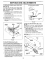
TO REPLACE
MOWER
BLADE
DRIVE
BELT
WITH PARKING BRAKE "ENGAGED"
(See Fig. 25)
The mower blade drive belt may be replaced without
tools. Park the tractor on level surface. Engage parking
brake. For assistance, there is a belt installation guide
decal on the mower housing.
BELT REMOVAL •
Place attachment clutch in "DISENGAGED" position.
•
Move attachment lift lever forward to lower mower to
its lowest position.
•
Roll belt off engine pulley.
•
Work belt off both mandrel pulleys and idler pulleys.
N_T "A"
NUT
•
Pull belt away from mower.
BELT INSTALLATION •
Install new belt in reverse order of removal.
•
'_
PERATING
ARM
Make sure belt is in all pulley grooves and inside all
belt guides.
FIG. 26
ENGINE PULLEY
MANDREL
PULLEY
TO REPLACE
Fig. 27)
IDLER
PULLEYS
MOTION
DRIVE
BELT (See
Park the tractor on level area. Engage parking brake.
For assistance, there is a belt installation guide decal on
bottom side of left footrest.
•
Remove mower (See "TO REMOVE MOWER" in this
section of this manual).
•
Remove belt from stationary idler and clutching idler.
•
Remove belt from engine pulley.
,,
Roll belt over top of transaxle pulley.
•
Install new belt by reversing above procedure.
IMPORTANT:
REPLACE
IN THIS MANUAL.
ONLY WITH
MANDREL
PULLEY
BELT LISTED
FRAME
FIG. 25
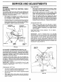
TO ADJUST BRAKE (See Fig. 26)
Your unit is equipped with an adjustable brake system
which is mounted on the right side of the transaxle.
If unit requires more than six (6) feet stopping distance at
high speed in highest gear, then brake must be adjusted.
•
Depress clutch/brake pedal and engage parking brake.
•
Measure distance between brake operating arm and
nut "A" on brake rod.
•
If distance is other than 1-1/2", disengage parking
brake, loosen jam nut and turn nut "A" until distance
becomes 1-1/2". Retighten jam nut against nut-"A"_
•
Engage parking brake and recheck distance.
•
Road test unit for proper stopping distance as stated
above. Readjust if necessary. If stopping distance is
still greater than six (6) feet in highest gear, further
maintenance is necessary. Contact your nearest authorized service center.
CLUTCHIN(
TRANSAXLE
PULLEY
STATIONARY
IDLER
ENGINE
PULLEY
FIG. 27
21
SERVICE AND ADJUSTMENTS
TO ADJUST
STEERING
WHEEL
ALIGNMENT
TO START ENGINE WITH A WEAK
(See Fig, 29)
If steering wheel crossbars are not horizontal (left to right)
when wheels are positioned st raight forward, removesteering wheel and reassemble per instructions in the Assembly
section of this manual.
CAUTION: Lead-acid batteries generate explosive gases. Keep sparks, flame
and smoking materials away from batteries.
Always wear eye protection
when around batteries.
FRONT WHEEL TOE'IN/CAMBER
The front wheel toe-in and camber are not adjustable on
your tractor. If damage has occurred to affect the front
wheel toe-in or camber, contact your nearest authorized
service center.
TO REMOVE
WHEEL
FOR REPAIRS
If your battery is too weak to start the engine, it should be
recharged. If "jumper cables" are used for emergency
starting, follow this procedure:
IMPORTANT:
YOUR UNIT IS EQUIPPED WiTH A 12
VOLT NEGATIVE GROUNDED SYSTEM. THE OTHER
VEHICLE MUST ALSO BE A 12 VOLT NEGATIVE
GROUNDED SYSTEM. DO NOT USE YOUR TRACTOR
BATTERY TO START OTHER VEHICLES.
(See
Fig. 28)
*
Block up axle securely.
,
Remove axle cover, retaining ring and washers to allow
wheel removal (rear wheel contains a square key - Do
not lose).
o
Repair tire and reassemble.
*
On rear wheels only: align grooves in rear wheel hub
and axle. Insert squarekey.
-
Replace washers and snap retaining ring securely in
axle groove:
=
Replace axle cover.
BATTERY
TO ATTACH JUMPER CABLES •
Connect each end of the RED cable to the POSITIVE
(+) terminal of each battery, taking care not to short
against chassis.
•
Connect one end of the BLACK cable to the NEGATIVE (-) terminal of fully charged battery.
•
Connect the other end of the BLACK cable to a good
CHASSIS G ROU ND, away from fuel tank and battery.
TO REMOVE CABLES, REVERSE ORDER •
•
WASHERS
BLACK cable first from chassis and fully charged
battery.
RED cable last from both batteries.
POSITIVE TERMINAL
NEGATIVE TERMINAL
RETAINING
RING
Q
AXLECOVER
I
_. SQUAREKEY
(REAR WHEEL ONLY)
FIG. 28
CABLES
CHARGED
BA'FrERY
!
................
....................
POSITIVE TERMINAL
"
NEGATIVE TERMINAL
FIG. 29
22
Fir
SERVICE AND ADJUSTMENTS
TO REPLACE
FUSE (See Fig. 30)
TO REMOVE
Replace with 30 amp automotive-type plug-in fuse. The
fuse holder is located in the engine compartment, directly
in front of the dash.
i
FUSE
HOLDER
HOOD AND GRILL
(See Fig. 31)
when removing retainer spdngs from
CAUTION:
Muffler is hot. Be careful
hood pivot brackets.
_
°
Raise hood.
•
Unsnap headlight wire connector.
•
Remove retainer springs from hood pivot brackets.
°
Stand in front of tractor. Grasp
forward and lift off of tractor.
•
To reinstall, slide hood pivot brackets into slots in
frame. Replace retainer springs.
Reconnect headlight wire connector and close hood.
o
hood at sides, tilt
HEADLIGHT
WIRE
CONNECTOR
HOOD
FIG. 30
TO REPLACE
HEADLIGHT
BULB
•
Raise hood.
•
Pull bulb holder out of the hole in the backside of the
grill.
•
Replace bulb in holder and push bulb holder securely
back into the hole in the backside of the grill.
Close hood.
•
INTERLOCKS
AND RELAYS
REMOVE
RETAINER
SPRINGS
Loose or damaged wiring may cause your tractor to run
poorly, stop running or prevent it from starting.
°
Check wiring. See electrical wiring diagram in Repair
Parts section of this manual.
FIG. 31
23
!
SERVICE AND ADJUSTMENTS
FINAL SE-I-rING -
ENGINE
TO ADJUST THRO'I-rLE
(See Fig. 32)
CONTROL
CABLE
The throttle control has been preset at the factory and
adjustment should not be necessary. Checkadjustment as
described below before loosening cable. If adjustment is
necessary, proceed as follows:
,,
With engine not running, move throttle control lever
from "SLOW" to "CHOKE" posit_on. Slowly move lever
from "CHOKE" to "FAST" position.
,,
Checkthat holes "A" in governorcontro! leverand hole
in governor plate line-up. If holes "A" are not aligned,
Ioosenclamp screw and movethrottle cable until holes
are aligned. Tighten clamp screw securely.
"
Start engine and allow to warm for five minutes. Make
final adjustments with engine running and shift/motion
control lever in "NEUTRAL" position.
,,
Move throttle control lever to "SLOW" position. With
finger, rotate and hold throttle lever against idle speed
screw. Turn idle speed screw to attain 1750 RPM.
•
While still holding throttle lever against idle speed
screw, turn idle rnixture valve in (clockwise) until engine beginsto die and then turn out (cou nterclockwise)
until engine runs rough. Turn valve to a point midway
between those two positions. Release throttle lever.
ACCELERATION
•
GOVERNOR
CONTROLLEVER
TEST -
Move throttle control lever from "SLOW" to "FAST"
position. If engine hesitates or dies, turn idle mixture
valveout (counterclockwise) 1/8turn. Repeattest and
continue to adjust, if necessary, until engine accelerates smoothly.
GOVERNOR
CONTROLPLATE
High speed stop is factory adjusted.
damage may result.
Do not adjust -
IMPORTANT:
NEVER TAMPER
WITH THE ENGINE
GOVERNOR,
WHICH IS FACTORY SET FOR PROPER
ENGINE SPEED. OVERSPEEDINGTHE
ENGINE ABOVE
THE
FACTORY
HIGH
SPEED
SETTING
CAN
BE
DANGEROUS.
IF YOU THINK THE ENGINE-GOVERNED
HIGH SPEED NEEDS ADJUSTING,
CONTACT
YOUR
NEAREST AUTHORIZED
SERVICE CENTER, WHICH HAS
PROPER EQUIPMENT AND EXPERTENCE TO MAKE ANY
NECESSARY
ADJ USTM ENTS.
HOLES"A"
CLAMP
SCREW
THROTTLE
CABLE
FIG. 32
TO ADJUST
CARBURETOR
THROTTLE
LEVER
IDLE SPEED
SCREW
(See Fig. 33)
The carburetor has been preset at the factory and adjustment should not be necessary. However, minor adjustment may be required to compensate for differences in fuel,
temperature, altitude or load. If the carburetor does need
adjustment, proceed as follows:
In general, turning idle mixture valve in (clockwise) decreases the supply of fuel to the engine giving a leaner fueV
air mixture. Turning the idle mixture valve out (counterclockwise) increases the supply of fuel to the engine giving
a richer fuel/air mixture.
IMPORTANT: DAMAGE TO THE NEEDLE VALVE AND
THE SEAT IN CARBURETOR MAY RESULT IF SCREW IS
TURNED IN TOO TIGHT.
J
J
PRELIMINARY SETTING -
Air cleaner assembly must be assembled to the carburetor when making carburetor adjustments ...........
"
Be sure the throttle control cable is adjusted properly
(see above).
-
With engine off turn idle mixture valve in (clockwise)
closing it finger tight and then turn out (counterclockwise ) 1 full turn.
IDLEMIXTURE
VALVE
FIG. 33
24
.....
STORAGE
ENGINE
Immediately prepare your tractor for storage at the end of
t he season or ifthe unit will not be used for 30 days or more.
__fore
FUEL SYSTEM
IMPORTANT:
IT IS IMPORTANT TO PREVENT GUM
DEPOSITS FROM FORMING IN ESSENTIAL
FUEL
SYSTEM PARTS SUCH AS CARBURETOR, FUEL FILTER,
FUEL HOSE, OR TANK DURING STORAGE.
ALSO;
EXPERIENCE INDICATES THAT ALCOHOL BLENDED
FUELS (CALLED GASOHOL OR USING ETHANOL OR
METHANOL) CAN ATTRACT MOISTURE WHICH LEADS
TO SEPARATION AND FORMATION OF ACIDS DLIRING
STORAGE.
ACIDIC GAS CAN DAMAGE THE FUEL
SYSTEM OF AN ENGINE WHILE IN STORAGE.
sCAU'FION: Never store the tractor with
where fumes may reach an open flame
gasoline in the tank inside a building
or spark.
Allow the engine to cool
toring in any enclosure.
TRACTOR
-
Drain the fuel tank.
Remove mower from tractor for winter storage. When
mower is to be stored for a period of time, clean it thoroughly, remove all dirt, grease, leaves, etc. Store in a
clean, dry area.
,
Start the engine and let it run until the fuel lines and
carburetor are empty.
•
Never use engine or carburetor cleaner products in the
fuel tank or permanent damage may occur.
Use fresh fuel next season.
Clean entire tractor (See"CLEANING" in the Customer
Responsibilities section of this manual).
o
•
NOTE: Fuel stabilizer is an acceptable alternative ' in
minimizing the formation of fuel gum deposits during storage. Add stabilizer to gasoline in fuel tank or storage
container. Always follow the mix ratio found on stabilizer
container. Run engine at least 10 minutes after adding
stabilizer to allow the stabilizer to reach the carburetor. Do
not drain the gas tank and carburetor if using fuel stabilizer.
Inspect and replace belts, if necessary (See belt replace ment instructionsin the Service and Adjustments
section of this manual).
Lubricate as shown in the Customer Responsibilities
section of this manual.
Be sure that all nuts, bolts and screws are securely
fastened. Inspect moving partsfordamage, breakage
and wear. Replace if necessary.
•
ENGINE OIL
Touch up all rusted or chipped paint surfaces; sand
lightly before painting.
Drain oil (with engine warm)and replace with clean engine
oil. (See "ENGINE" in the Customer Responsibilities
section of this manual).
BA'n'ERY
•
Fully charge the battery for storage.
CYLINDERS
=
After a period of time in storage, battery may require
recharging.
•
Remove spark plug(s).
•
Pour one ounce of oil through spark plug hole(s) into
cylinder(s).
•
Turn ignitionkey to"START" position for a few seconds
to distribute oil.
•
Replace with new spark plug(s).
To help prevent corrosion and power leakage during
long periods of storage, battery cables should be
disconnected and battery cleaned thoroughly (see"TO
CLEAN BATTERY AND TERMINALS" in the Customer Responsibilities section of this manual).
.
After cleaning, leave cables disconnected and place
cables where they cannot come in contact with battery
terminals.
•
Be sure battery drain tube is securely attached.
OTHER
Do not store gasoline from one season to another.
•
Replace your gasoline can if your can starts to rust.
Rust and/or dirt in your gasoline will cause problems.
•
If possible, store your unit indoors and cover it to give
protection from dust and dirt.
°
Cover your unit with a suitable protective cover that
does not retain moisture. Do not use plastic. Plastic
cannot breathe which allows condensation to form and
will cause your unit to rust.
IMPORTANT: NEVER COVER TRACTOR WHILE ENGINE
AND EXHAUST AREAS ARE STILL WARM.
25
TROUBLESHOOTING
PROBLEM
Will not start
CAUSE
NTS
CORRECTION
1.
Out of fuel.
2.
3.
4.
5.
6.
7.
Engine not "CHOKED" properly.
Engine flooded.
Bad spark plug.
Dirty air filter.
Dirty fuel filter.
Water in fuel.
1.
2.
3.
4.
5.
6.
7.
8.
9.
10.
Loose or damaged widng.
Carburetor out of adjustment.
Engine valves out ef adjustment.
8.
9.
10.
Fill fuel tank.
See "TO START ENGINE" in Operation section.
Wait several minutes before attempting to start.
Replace spark plug.
Clean/replace air filter.
Replace fuel filter.
Drain fuel tank and carburetor, refill tank with fresh
gasoline and replace fuel filter.
Check all wiring.
Contact an authorized serVice facility.
Contact an authorized serVice facility.
i
i
Hard to start
1.
2.
3.
4.
5.
6.
7.
8.
Dirtyairtiiter.
Bad spark plug.
Weakordead
battery.
Dirty fuel filter.
Stale or dirty fuel.
Loose er damaged wiring.
Carburetor out of adjustment.
Engine valves out of adjustment.
1.
2.
3.
4.
5.
6.
7.
8.
Clean/replace air filter.
Replace spark plug.
Recharge or replace battery.
Replace fuel filter.
Drain fue! tank and refill with fresh gasoline.
Check all wiring.
Contact an authorized serVice facility.
Contact an authorized serVice facility.
Engine will not turn over
1.
2.
3.
4.
Clutch/brake pedal not depressed.
Attachment clutch is engaged.
Weak or dead battery.
Blown fuse.
5.
6.
7.
8.
9.
Corroded battery terminals.
Loose or damaged wiring.
Faulty ignition switch.
Faulty solenoid or starter.
Faulty operator presence switch(ee).
1.
2.
3.
4.
5.
6.
7.
8.
9,
Depress clutch/brake pedal.
Disengage attachment clutch.
Recharge or replace battery.
Replace fuse.
Clean battery terminals.
Check all wiring.
Check]replace ignition switch.
Check]replace solenoid orstarter.
Contact an authorized service facility.
Engine clicks but will not
start
1.
2.
3.
4.
Weakordead
battery.
Corroded battery terminals.
Loose or damaged wiring.
Faulty solenoid or starter.
1.
2.
3.
4.
Recharge or replace battery.
Clean battery terminals.
Check all wiring.
Check]replace solenoid or starter.
Loss of power
1.
2.
3.
4.
5.
6.
7.
8.
9.
Cutting too much grass/too fast.
Throttle in "CHOKE" position.
Build-up of grass, leaves and trash under mower.
Dirty air filter,
Low oil leve!/dirty oil.
Faulty spark plug.
Dirty fuel filter.
Stale or dirty fuel.
Water in fuel
1.
2.
3.
4.
5.
6.
7.
8.
9.
Set in "Higher Cut" position/reduce speed.
Adjust throttle control:
Clean underside of mower housing.
Clean/replace air filter.
Check oil level/change oil.
Clean and regap or change spark plug.
Replace fuel filter.
Drain fuel tankand refill with fresh gasoline.
Drain fuel tank and carburetor, mfifi tank with fresh
10.
11.
12.
13.
14.
15.
Excessive
vibration
Spark plug wire loose.
Dirty engine air screen/tins.
Dirty/clogged muffler.
Loose or damaged wiring.
Carburetor out of adjustment.
Engine valves out of adjustment.
!.
2.
Worn, bent or loose blade.
Bent blade mandrel.
3:
Loose/dam age d part(_',
10.
tl.
12.
13.
14.
15.
1.
2t
3.
26
gasoline and replace fuel filter.
Connect and tighten spark plug wire.
Clean engine air screen/fins.
Cleanlreplace muffler.
Checkall wiring.
Contact an authorized service facility.
Contact an authorized service facility.
Replace blade. Tighten blade bolt.
Rep!aceblade mandre.
....
Tighten loose part(s). Replace damaged parts.
.
TROUBLESHOOTING
=
,
_
lr
POINTS
==,_ n=
w
CORRECTION
PROBLEM
CAUSE
Engine continues torun
when operstorleavesseat
with at_chment_utch
1.
Faulty operator-safety presence
1.
2.
3.
4.
Worn, bent or loess blade.
Mower deck not level.
Buildup of grass, leaves, and trash under mower.
Bent blade mandrel.
5.
Clogged mower deck vent holes from buildup of
grass, leaves, and trash around mandrels.
Mower blades will not
rotate
1.
2.
3.
4.
Poor grass discharge
1.
Check widng, switches and connections.
If not
corrected, contact an authorized service facility.
1.
2.
3.
4.
5.
Replace blade. Tighten blade holt.
Level mowerdeck.
Clean underside of mower housing.
Replace blade mandrel.
Clean around mandrels to open vent boles.
Obstruction in clutch mechanism.
Wom/damaged mower drive belt.
Frozen idler pulley.
Frozen blade mandrel.
1.
2.
3.
4.
Remove
Replace
Replace
Replace
1.
2.
3.
4.
Engine speed too stow.
Travel speed too fast.
Wet grass.
Mower deck not level.
1.
2.
3.
4.
Place throttle cor_trol in "FAST" position.
Shift to slower speed.
A]Iow grass to dry before mowing.
Level mower deck.
5.
6.
7.
8.
Low/uneven tire air pressure.
Worn, bent or loose blade.
Buildup of grass, leaves and trash under mower.
Mower drive belt worn.
9.
10.
11.
Blades improperly installed.
Improper blades used.
Clogged mower deck vent holes from buildup el
grass, leaves, and trash around mandrels.
control system.
engaged
Poor cut - uneven
m
Headlight(s) not working
(if so equipped)
5.
6.
7.
8.
9.
10.
lt.
obstnJction.
mower dr_ve belt.
idler pulley.
blade mandrel.
Checktires for proper air pressure.
Reptacelsharpen blade. 3qghten blade bolt.
Clean underside of mower housing.
Replace mower drive belt.
Reinstall blades sharp edge down.
Replace with blades listed in this manual.
Clean around mandrels to open vent holes.
1.
Switch is "0 FF".
1.
Turn switch "ON".
2.
3.
4.
5.
Bulb(e) burned out.
Faulty light switch.
Loose or damaged wiring.
Blown fuse.
2.
3.
4.
5.
Replace bulb(s).
Checldreplace light switch.
Check wiring and connections.
Replace fuse.
1.
2.
Bad battery celi(s).
Poor cable connections.
1.
2.
Replace battery.
CheokJc_ean all connections.
3.
4.
Faulty regulator (if so equipped).
Faulty alternator.
3.
4.
Replace regulator.
Replace alternator.
!
Battery will not charge
Engine "backfires"
when turning engine
"OFF"
Engine throttle control not set at "SLOW"
position for 30 seconds before stopping engine.
27
Move throttle control to 'SLOW' position and allow
to idle for 30 seconds before stopping engine.
•
SERVICE NOTES
28
j,,
12.5 HP 42" RIDING LAWN TRACTOR
= = MODEL NUMBER
917.255581
SCHEMATIC
ollio
÷Ill--
RED
BATTERY
| .....
I
RED
I
RED
!
I
FUSE 30 AMP.
WHITE
I
=
I
I
_
I
STARTER
L
IF
SOLENOID
BLACK
IGNITION SWITCH
I
I
-
1
l
L) I
I
_7
j
I
I
I
I
If-.,
I
CLUTCH/BRAKE
(PEDAL
UP)
BLACK
7I
I
.,-_.
I
BLACK
I
I
I
I
I
I
I
t_
I
I
BLACK
SEAT
SWITCH
(NOT OCCUPIED)
(CLUTCH OFF)
BLACK
(_
IGNITION
UNIT
PLUG
SPARK
b
RED
3 AMPS DO
@ 3600 RPM
(BATTERY IN LINE)
ALTERNATOR
"
20 VOLTS AC (MIN.)
NOTE
ORA.GE CL
YOUR TRACTOR IS EQUIPPED
"_" 5 AMPS
ALTERNATOR
WITH A SPECIAL ALTERNATOR
SYSTEM. THE LIGHTS ARE NOT
CONNECTED TO THE BA-I-FERY,
@ 11 VOLTS AC @ SSGO RPM.
BUT HAVE THEIR OWN
ELECTRICAL SOURCE.
BECAUSE
OF THIS, THE BRIGHTiGNITION SWITCH
NESS OF THE LIGHTS WILL
CHANGE WITH ENGINE SPEED.
POS|TION
CIRCUIT
AT IDLE THE LIGHTS WILL DIM.
OFF
M + G
AS THE ENGINE IS SPEEDED UP,
ON
B+L
THE LIGHTS WILL BECOME
START
B+ S
THEIR BRIGHTEST.
WIRING INSULATED CLIPS
............
_
...........................
NOTE: If wiring ;nsulated clips were reNON-REMOVABLE
_4_-REMOVABLE
moved for servicing of unit, they should
CONNECTIONS
CONNECTIONS
be replaced to properly secure your wiring.
29
D
P
,"-/"7
REPAIR PARTS
12.5 HP 42" RIDING LAWN TRACTOR
- - MODEL NUMBER
ELECTRICAL
A
B
C
D
E
F
32
12
13
0
35
33
37
\
t
L
28
I
I
I
/
I
I
I
II
Ill
It
I
I
\
I
3O
917.255581
REPAIR PARTS
12.5 HP 42" RIDING LAWN TRACTOR
° - MODEL NUMBER
917.255581
ELECTRICAL
KEY PART
NO. NO.
DESCRIPTION
1
2
3
4
5
6
7
8
9
10
11
12
13
14
15
16
17
18
19
20
Battery 12 Volt 25 Amp
Starter Swtc
Nut ignition
Harness Ign B&s Fender HI
Cable Ground 6ga 12 black
Cable Battery 6 Ga 43"red
Cable Battery 6ga 11 "red
Case Battery Hng Mech W/lid
Clamp Hose Olive
Solenoid
Lockwasher
Nut Jam Hex 1/4-20 Unc
Bolt Fin Hex 1/4-20uncx1/2 Gr5
Washer
Nut
Cover Termina! Red
Switch Intlk Clutch Red 4 Term
Screw
Switch lntlk Clutch Red 2 Term
Screw
121265X
STD365402
124211X
132653
4207J
132202
4799J
129965
109596X
109081X
STD551125
73350400
74780408
STD551225
STD541425
131563
109553X
STD601005
!04445X
STD601005
KEY PART
NO, NO.
DESCRIPTION
21
22
23
24
25
26
27
2B
29
30
31
32
33
34
35
36
37
Switch Plunger Nc Gray
Caps Battery 20/25/30 Amp
Bolt Hex Hd 1/4-20unc X 3/4
Washer
Washer
Nut
Key Ign Molded Craftsman
Fuse 30 Amp Auto Green
Tube Plastic 12"
Cover Sw Key BIk 1 25 Text Sit
Switch Light BIk BIk Red
Harness ,_JocketLight
Bulb Light #1141
Bracket Switch Clutch
Screw
Bracket Switch interlock
Screw
121305X
121264X
74760412
STD551025
STD551125
STD541025
109310X
108824X
109238X
123620X
110712X
127441X
7662J
108236X
STD601005
130890
STD601005
NOTE: All component dimensions given in U.S. inches
1 inch = 25.4 mm
31
REPAIR PARTS
12.5 HP 42" RIDING LAWN TRACTOR
CHASSIS
= - MODEL NUMBER 917,255581
AND ENCLOSURES
A
B
D
E
F
G
I
K
L
29
9
28
10
J
!
E
o_; ,! o
6
21_
22
18
"
21
11
17
37
8
3O
33
13
G
31
32
REPAIR PARTS
12.5 HP 42" RIDING LAWN TRACTOR
CHASSIS
- - MODEL NUMBER
917.255581
AND ENCLOSURES
KEY
NO.
PART
NO.
1
2
3
6
7
8
9
10
11
12
13
14
15
16
17
18
19
20
21
135034
130805
17490612
126595X010
17490608
126471X
126604X010
5479J
135464
121794X
124031X012
17490608
74180512
STD541431
131445X459
126938X
STD512505
STD551125
122933X
DESCRIPTION
Chassis Weldment
Drawbar 11 Ga 46 5"wheel Base
Screw Thdrol 3/8-16x3/4 Ty-tt
Saddle Silkscreened
Screw Thdrol 3/8-16xl/2 Ty-tt
Clip insulated 406 Mtg Hole
Dash Silkscreened Sears Eng
Plug Button BIk 359 Dia
Panel Pnt Dash Lh
Cover Access Black Square
Panel Slkscr Dash Rh Weldment
Screw Thdrol 3/8-18xl/2 Ty-tt
Screw Mach Trhd 5/16-18uncx3/4
Nut
Hood Asm Pnt Weld Dover Slpe
Bumper Hood
Screw
Washer
Rivet Ratchet Nylon
KEY
NO,
PART
NO,
22
23
24
25
26
27
28
29
30
31
32
33
34
35
36
37
38
39
124479X
4921H
STD523707
19131312
STD541437
17490808
126741X
124029X
126599X459
109873X
17490612
105465X459
105464X459
STD533707
STD541437
105466X
134775
134774
DESCRIPTION
Washer Nylon BIk 28x 75x 19
Retainer Spring
Bolt
Washer 13/32 X 13/16 X 12 Ga
Nut
Screw Thdrol 3/8-16xl/2 Ty-tt
Grille Black
Lens Headlight Bar Clear
Fender Pnt
Bracket Pnt Fender
Screw Thdrol 3/8-16x3/4 Ty-tt
Footrest Pnt Lh
Footrest Pnt Rh (dover Gray)
Bolt
Nut
Pad Footrest Rbr Sq Craftsman
Bracket, Assembly, Pivot R.H.
Bracket, Assembly, Pivot L.H.
NOTE: All component dimensions given in U.S. inches
1 inch = 25.4 mm
33
REPAIR PARTS
12.5 HP 42" RIDING
LAWN TRACTOR
- - MODEL NUMBER 917.255581
DRIVE
89
45
37
22
36
23
27
77
___
..........
_--.
:.
_ ;,
A
i._*',_"._
_ 9_
34
B
C
D
E
F
G
_ s_
H
I
J
REPAIR PARTS
12.5 HP 42" RIDING LAWN TRACTOR
'- MODEL NUMBER
917,255581
DRIVE
KEY PART ;,
NO. NO.
DESCRIPTION
1
2
3
4
5
6
8
10
11
12
13
14
17
18
19
20
21
22
23
24
25
26
27
28
29
30
31
32
33
34
35
36
37
38
39
40
41
42
43
44
45
46
47
48
49
Transaxle 6 sp. Dana 4360-7
Spring Extension Brake
Pulley Transaxle 18"tires
Ring Retainer # 5100-62
Strap Torque Rh Pnt BIk
Screw Thdrol 5/16-18 X 3/4 Tyt
Lever Shift Weld Pnt
Pin Cotter
Washer Shift Plate
Washer 15/32x3/4x16Ga.
Bolt Fin Hex 1/4-28unfx3/4 Gr8
Washer
Strap Pnt Torque Lh
Bolt
Nut
Screw Thdrol 3/8-16x3/4 Ty-tt
Knob Rd 1/2-13 Plstc Thds BIk
Rod, Brake
Locknut
Nut
Spring Rod Brake 2 00 Zinc
Washer
Pin
Rod Brake Parking Lt
Cap Parking Brake Red
Bracket Mtg Transaxle
Keeper Belt Lh Lt 14 Ga
Bolt
Nut
Shaft Asm Pedal Foot 1 930
Bearing Nylon BIk 629 Id
Washer
Roll Pin
Pulley Idler Flat
Bolt
Spacer Split 395 X 59 Bzp
Keeper Belt Retainer
Washer 13/32 X 13/16 X 12 Ga
Nut
Bearing, Nylon
Washer Hardened
Ring Klip #t5304-50
Pulley Idler V Groove Ptastic
Bellcrank Asm
Retainer Belt Style Spring
120898X
110422X
123666X
12000028
121520X
17490512
127270
76020416
105701X
19151216
71040412
STD551125
121250X
S'i'D523707
STD541437
17490512
106933X
130804
STD541437
STD541237
106888X
STD551037
STD581210
128904
124236X
130807
127275X
STD523107
STD541431
122424X
120183X
STD551062
STD571810
123674X
STD523727
4470J
109070X
19131312
STD541437
105706X
110812X
12000039
127783
123789X
123205X
KEY PART
NO. NO.
50
51
52
53
54
55
56
57
58
59
60
61
62
63
64
65
68
67
68
69
70
71
72
73
74
75
76
77
78
80
81
82
83
84
85
86
87
88
89
90
91
100
STD523715
STD541437
STD551037
105710X
STD561210
105709X
STD561210
130801
127274X
104777X
19131312
17490612
8883R
134825
71170764
STD551143
129921
STD523710
19131312
STD541437
134683
STD523710
19132012
STD541437
109502X
121749X
STD581075
123583X
121748X
131488
136932
123782X
19171216
132182
73530400
71208
1'9212016
12000008
131636
t24346X
STD523707
17490612
DESCRIPTION
Bolt
Nut
Washer
Link Clutch 7 66
Pin
Spring Return Clutch 6 75
Fill
V-bett Ground Drive 95 25
Keeper Belt Rh Lt PntJzinc 16g
Retainer Belt Chassis Lh Zinc
Washer 13/32 X 13/16 X 12 Ga
Screw Thdrol 3/8-16x3/4 Ty-tt
Cover Pedal BIk Round
Pulley Engine
Bolt Fin Hex 7/1 6-20 x 4 Gr.5
Washer
Keeper Belt Engine Lh Lt
Bolt
Washer 13/32 X 13/16 X 12 Ga
Nut
Guide Belt Dr Mower Rh
Bolt
Washer 13/32 X 1-1/4 X 12 Ga
Nut
Spacer Split 80 X 94
Washer 25/32 X 1 1/4 X 16 Ga
E Ring
Key Square 2 0 X 1845/1865
Washer 25/32 X 1 5/8 X 16ga
Arm, Shift
Shaft Asm., Cross Stretch
Spring Torsion
Washer 17/32 x 3/4 x 16 Ga.
Rod Tie Shft. Adj. Ball
Nut, Nylock
Bushing Pivot
Washer
Ring, E
Console Shift 6sp W/ign Lt
Nut Self-thd Wsh-hd 1/4 Zinc
Bolt
Screw Thdrol 3/8 - 16 x 3/4
NOTE: All component dimensions given in U.S. inches
1 inch = 25.4 mm
35
/
3_
REPAIR PARTS
12.5 HP 42" RIDING LAWN TRACTOR
STEERING
- - MODEL NUMBER
917.255581
ASSEMBLY
KEY
NO.
PART
NO.
1
2
3
4
5
6
7
8
9
10
11
12
13
14
15
16
17
18
19
20
21
22
23
133741
131450
135227
135228
6266H
121748X
19272016
12000029
3366R
130468
STD551137
73610600
110438X
74011056
73601000
!32624
132614
57079
124035X
126684X
S'1"D551125
71070410
127501
DESCRIPTION
Wheel Steering
Axle Asm Front
Spindle Asm Lh
Spindle Asm Rh
Bearing Race Thrust Harden
Washer 25/32 X 1 5/8 X 16ga
Washer 27/32 X 1 1/4 X 16 Ga
Ring Klip #t5304-75
Bearing Col Strg BIk
Link DragSol Ball Jt 20 064
Lockwasher
Nut Fin Hex 3/8-24 Unf
Spacer Bearing Axle Front
Bolt Hex 5/8-11 Unc X 3-1/2
Nut Hex Jam Lk W/wh 5/8-11 Unc
Pin Axle 5/8 X1 55/1 54Lg
Shaft Asm Strg 5/8 X 15 19 Lt
Washer Thrust 515x 750x 033
-Support Shaft
Washer Shim 1/4 X 5/8 X 062
Washer
Screw Hex Socket 1/4-20 X 5/8
Shaft Asm Pittman
KEY
NO.
PART
NO.
24
25
26
27
28
29
30
31
32
33
34
35
36
37
38
39
40
41
42
43
44
45
46
109816X
124036X
12000029
124034X
6266H
17490612
STD551137
73610600
130465
120754X
19131416
STD561210
132196
STD811005
133742
19133808
STD541537
104820X
124417X
121749X
121748X
12000029
121232X
DESCRIPTION
Nyliner Snap In
Bracket Steering
Ring Klip #t5304-75
Gear Sector
BearingRace Thrust Harden
ScrewThdrol 3/8-16x3/4 Ty-tt
Lockwasher
Nut Fin Hex 3/8-24 Unf
Rod Tie Wire Form 19 75 Mech
Bushing Rod Tie BIk Lt
Washer 13/32 X 7/6 X 16ga
Pin
Bushing Strg 5/8 Id Dash
Screw
Insert Cap Strg Wh Au Gen BIk
Washer 13/32 X 2-3/8 X 8 Ga
Gripco NUt
Adaptor Wheel Strg 640/635id
Boot Shaft Steering
Washer 25/32 X 1 1/4 X 16 Ga
Washer 25/32 X 1 5/8 X 16ga
Ring Klip #t530_-_75
Cap Spindle Fr Top BIk
NOTE: A(I component dimensions given in U.S. inches
1 inch = 25.4 mm
/
37
REPAIR PARTS
12.5 HP 42" RIDING
LAWN TRACTOR
- - MODEL NUMBER 917.255581
SEAT ASSEMBLY
10
11
t.
...
"- Sa,
.,,>/. I -.,
%
x
f
/
{
15
,!
=
16
15
12
A
_19
13
KEY PART
NO, NO.
1
2
3
4
5
6
7
8
9
10
11
12
13
14
127438X
126656X
STD523707
19131210
2751R
STD541437
124181X
1749061619131614
131451
121251X
121246X
121248X
72050411
B
KEY PART
NO. NO.
DESCRIPTION
Seat V-450 BIIdred Craftsman
Bracket Pnt Pivot Seat (blk)
Bolt
Washer13/32 X 3/4 X10 Ga
Clip Line Fuel 13/32 Mtg Hole
Nut
Spring Seat Cprsn 2 250 BIk Zi
ScrewTIidroi
318-16 X i ryLtt
.........
Washer 13/32 X 1 X 14 Ga
Pan Pnt Seat (blk)
Strip Foam Gray Or Black
Bracket Pnt Mounting Switch
Bushing Snap Blk Nyl 50 Id
Bolt Rdhd Sht Nk 1/4-20xl-3/8
15
16
17
18
19
20
21
22
23
24
25
26
134300
i21250X
123976X
STD511005
73951000
4171R
105529X
STD541431
74780814
19171912
127018X
STD551150
C
D
@6
E
_I'T
DESCRIPTION
Spacer Split 2B X 88 Zinc
Spring Cprsn 1 27 BIk Pnt
Nut Lock 1/4 Lge Fig Gr 5 Zinc
Screw
Nut Keps #10-32 Unf
Clip insulated 11/32 Mtg Hole
Bolt Shoulder 5/16-18 Unc Blkz
Nut
Bolt Fin Hex 1/2-13 X 7/8 Gr 5
Washer 17/32 X 1-3/16 X 12 Ga
Bolt Shoulder 5/16-18 X 62
Lockwasher
NOTE: All component dimensions given in U.S. inches
1 inch = 25.4 mm
38
REPAIR PARTS
12.5 HP 42" RIDING LAWN TRACTOR
- - MODEL NUMBER
917.255581
DECALS
9
13
18
6
3
7
19
5
11
15
7
4
10
8
12
16
13
2
14
KEY PART
NO. NO.
1
2
3
4
5
6
7
8
9
10
11
108456X
127908
128381
128382
132874
133644
136332
133178
128314
133796
4900J
WHEELS
KEY PART
NO. NO.
DESCRIPTION
Decal
Decal
Decal
Decal
Decal
Decal
Decal
Decal
Decal
Decal
Decal
Instruction Operat Eng
Eng 12 5hp Ic Gold Craft
Hood Rh Craftsman Lt4000
Hood Lh Craftsman Lt4000
Grille Lt4000 Craft Usa
Maint Cust Sears Domesti
Panel Side I/c Gold Wht
Mower 3 In One Conv
Fender Craftsman White
Caution English
Clutch/brake English
12
13
14
15
16
17
18
19
--
109199X
131473
130981
121343X
3713J
133179
132268
131265
135828
DESCRIPTION
Decal V-belt Dr Sch Tractor E
Decal Chassis 6sp 42"
Decal V-belt Schematic 42"eng
Decal Danger English
Decal Rota Blades English
Decal Mower Qc System
Decal Insr Wh Strg Crafts Usa
Decal, Lightbox Grill
Manual Owners
NOTE: All component dimensions given in U.S. inches
1 inch = 25.4 mm
& TIRES
KEY PART
NO. NO.
i,g
1
2
3
4
5
6
7
8
9
10
11
59192
65139
106222X
59904
106732X311
278H
9040H ....
106108X311
106268X
7152J
104757X
DESCRIPTION
Cap Valve Tire
Stem Valve
Tire F Ts 15 X 6 0 - 6 Service
Tube Front (Service Item Only)
Rim Asm 6"front White Service
Fitting Grease (Front Whee! Only)
Bearing Flange (Front Wheel Only)
Rim Asm 8"rear White Service
Tire R Ts 18x9 5-8 C Service
Tube Rear (Service Item Only)
Cap Axle BIk 1 50 X 1 00
11
NOTE: All component dimensions given in U.S. inches
1 inch = 25.4 mm
39
REPAIR PARTS
12.5 HP 42" RIDING
LAWN TRACTOR
- - MODEL NUMBER
917.255581
ENGINE
1
3O
36
F
32
37
29
/
OPTION
AL EQU IPM ENT
Spark Arrester
B
C
2
D
9
F_.
6
17
F
G
35
H
24
18
21
20
@1o
19
4O
REPAIR PARTS
12.5 HP 42" RIDING LAWN TRACTOR
.. - MODEL NUMBER
917.255581
ENGINE
KEY
NO.
!
2
3
4
5
6
7
8
9
10
11
12
13
14
15
16
17
18
19
20
PART
NO.
132759
17720410
131953
125610X
101326L
17030808
STD551025
STD551125
STD522510
STD541031
STD551131
71070510
125593X
13280324
13200300
STD551237
17490620 •
105736X
105839X
105838X
KEY
NO.
DESCRIPTION
Control Throt Rh BIk Pd115 10
Screw Hex Thd Cut 1/4-20x5/8 T
Engine B&s 12 5 Icq Dual 1 Vt
Muffler Exhaust B&s Lt Dom
Deflector Muffler # 222573
Screw Spiderloc Hexhd#Sxl/2 Ab
Washer
Washer
Bolt
Nut
Lockwasher
Screw Hexhd Cap 5/16-18x5/8
Gasket 1 313 Id Tin Plated
Nipple Pipe 3/8 Npt X 3"
Elbow Std 90 Degree3/8-18 Npt
Washer
ScrewThdrol 3/8-16x1-1/4 Tytt
Shield Pnt Heat
Receptacle _/4 Turn Dacrotized
Retainer 1/4 Turn 365odx 222id
21
22
23
24
25
26
27
29
30
31
32
33
34
35
36
37
38
PART
NO.
STD551025
123650X
128953X
STD601005
124027X
17030808
105037X
121851X
127057X
109202X
123549X
123487X
124028X
17490412
19091416
101335K
---
DESCRIPTION
Washer
Stud 1/4 Turn (replaces 105751
Shield Pnt Heat Browning Grass
Screw
Shield Pnt Heat Hood U
Screw Spiderloc Hexhd#Sxl/2 Ab
Strip Foam 16
Arrestor Spark
Pinch Weld Hood Black 2 00
Tank Fuel 1 25 Fr
Cap Asm Fuel W/sym Vented
Clamp Hose BIk
Bushing Snap Nyl BIk Fuel Line
Screw Hexwsh Thdrol 1/4-20x3/4
Washer 9/32 X 7/8 X 16ga
Line Fuel 9 50"
Plug Oil Drain (Order From Engine
Manufacturer)
NOTE: All component dimensions
1 inch = 25.4 mm
4i
given in U.S, inches
REPAIR PARTS
12.5 HP 42" RIDING LAWN TRACTOR
42" MOWER
-- MODEL NUMBER
9!7.255581
DECK
83
82
45
19
__4
17
18
\"
12
13
I
87
85
8
9
42
90 89
REPAIR PARTS
12.5 HP 42" RIDING LAWN TRACTOR
42" MOWER
6
7
8
9
10
11
12
13
14
15
16
17
18
19
20
21
22
23
24
25
26
27
28
29
33
34
35
36
37
38
39
40
41
42
43
44
45
46
47
917.255581
DECK
KEY PART
NO. NO.
1
2
3
4
5
- - MODEL NUMBER
130970
130969
110485X
128774
133172
129895
134149
129962
STD551137
850857
128961
130968
131491
131267
110452X
123713X
19111016 '
105304X
S'1"D541431
STD533106
STD624008
127218
73350800
130171
73800800
135388
135563
130832
134619
133844
78158
129963
129861
73050900
STD533717
133943
131494
122052X
19131612
133502
133503
S'i-D541437
72110618
133835
KEY PART
DESCRIPTION
NO, NO.
DESCRIPTION
Bolt Shldr 10-24 Zinc Gr 5 4-"_
Roller Asm Cam Follower 42"dec
Nut
Bolt Shoulder 5/1 6-18 Unc Blkz
Arm Asm Brake Pad
Washer Hardened Smaller
Spring Extension
Rod Pivot W/nibs
Cotter Pin
Rod Clutch Secondary W/nibs
Guard Mandrel Lh 42"
Rod Clutch Primary W/nibs
Nut
Trunnion Adj 3/8-16 Unc x 1 30
Retainer
Screw Hex Thd Cut 1/4-20x5/8 T
Bushing_ 747 Od x 794 Lg Brass
Spring Return
Arm Clutch Secondary
Bolt Shoulder 3/8-16 Unc 1 44
Ring Klip #t5304-75
Washer 25/32 x 1 5/8 X 16ga
Keeper Spring 4 000
Knob Rd 3/8-16 Plstc Thds BIk
Arm Asm Clutch Primary
Spring Clutch Mower 2 750 Zinc
E Ring
Washer 21/32 x 7/8 x 16ga
Shaft Asm Pnt Lft W/wo/inf Hgt
Pin Groove 1 500 Zinc
Bearing Nylon BIk 629 ld
Rod Asm Lever 9 219 Bend Stake
Spring Cprsn 3 750 Oiled
Plunger Lever Lift
Button Plunger Red
Grip Handle Fluted BIk
Bracket Stiffener
Cover 42" mulcher
Screw
Washer Lock #10
Washer #10
Nut Weld
Latch Assembly
Deck Assembly Complete
Mandrel Asm (Includes Key #'s 58,10-12 39 And 41)
NOTE: All component dimensions given in U.S. inches
1 inch = 25.4 mm
48
49
50
51
52
53
54
55
56
57
58
59
60
61
62
63
64
65
66
67
68
69
70
71
72
73
74
75
76
77
78
79
80
81
82
83
84
85
86
87
88
89
90
Housing Asm Mower 42"
V-belt Mower 42" 92 40
Bearing Ball Mandrel
Housing Mandrel Vented (machd)
Shaft Asm Mandrel
_nc_udes Key #6)
earing Ball #6204 (mandrel)
Blade 42"mower Mulching
Washer Hard Blade Mower Vented
Lockwasher
Bolt 3/8-24xl 25 Gr8 Patched
Stripper Mower Vented
Shield Deflector 42' Black
Rod Hinge 42"6 75 Wig
Bracket Deflector Mower 42"
Nut Push Phos & Oil
Spring Torsion Deflector 2 52
Washer 11/32 x 5/8x 16 Ga
Cap Sleeve 80x 112 BIk Mower
Nut
Bolt
Ret Spring
Link Front
Nut Jam Hex 1/2-13 Uric
Trunnion BIk Zinc
Nylon Washer Ins Nut 1/2-t3 Unc
Link Lift Rh
Pin Spring Sltd 5/16 x 750
Arm Suspension Rear
Link Lift Lh
Arm Asm Idler 42"
Bolt 5/16-18 x 1 25 T/t
Washer Spacer Mower Vented
Pulley Mandrel 42"
Nut 9!16top Lock Flng Oil Dip
Bolt
Washer Hardened
Pulley idler Flat
aaCerRetainer Pm Mower
sher 13/32 x I x 12 Ga
Spacer Arm Idler Upper Hdn 42"
Stiffener Arm Idler Upper 42"
Nut
Bolt Rdhd Sqnk 3/8-16 x 2-1/4
Fastner Christmas Tree
43
131340
133940
STD541410
1O5529X
131845
133944
131335
133551
STD560907
133504
134238
133550
STD541237
1332O5
STD624003
17720410
127498
13! 870
127847
128903
12000029
121748X
127845
106932X
133573
128759
STD581062
19211416
122507X
1 O5767X
120183X
122514X
122512X
122364X
122365X
125631 X
134753
134079
71161010
10071000
1906! 216
2029J
130758
133171
130794
REPAIR PARTS
12.5 HP 42" RIDING LAWN TRACTOR ° - MODEL NUMBER 917.255581
FOOTF_JDANA "rRANSAXLE
= MODEL NUMBER
4360=7
20
21
3O
31
26
27
32
33
36
35
19
37
19
41
54
44
_17
45
55
46
56
47
57
48
49
59
50
56
51
55
19
60
58
59
44
REPAIR PARTS
12.5 HP 42" RIDING LAWN TRACTOR
FOOTE/DANA
KEY PART
NO. NO.
120458X
2274J
3
4
5
6
7
8
12
13
14
15
16
17
18,
19
20
21
22
23
24
25
26
27
28
29
3O
31
32
33
34
35
36
37
38
68003
105904X
105905X
120460X
120461X
120462X
120463X
120464X
120465X
120466X
83818
120467X
2286J
22.67J
3413J
2233J
2232J
2231J
2230J
2229J
2228J
2227J
2226J
105906X
6725J
120415X
2257J
110077X
110076X
105909X
105910X
105911X
108976X
105913X
120468X
2242J
120469X
2244J
105916X
120470X
110070X
108977X
109254X
120405X
108980X
120406X
10B455X
105925X
2232J
108978X
110079X
39
40
12047iX
120472X
9
10
11
....
_
TRANSAXLE
- - MODEL NUMBER
917.255581
- MODEL NUMBER4360-7
DESCRIPTION
Housin& Upper
Screw,Tapping, Large
1/4-20 x .734
Ball, Detent
Spring, Detent
Screw, Set
Shifter Assembly
O-Ring
* Washer, Plain .505 x .942 x .006
* Washer, Plain .505 x .942 x .010
* Washer, Plain .505 x .942 x .015
* Washer Plain .505 x .942 x .020
* Washer Plain .505 x .942 x .026
* Washer Plain .505 x .942 x .030
* Washer Plain .505 x .942 x .040
Ring, Retaining
Ring, Retaining
* Washer. Plain .632 x 1.00 x .010
* Washer Plain .632 x 1.00 x .020
* Washer Plain .632 x 1.00 x .026
* Washer Plain .632 x 1.00 x .031
* Washer Plain .632 x 1.00 x .036
* Washer Plain .632 x 1.00 x .041
* Washer Plain .632 x 1.00 x .046
* Washer Plain .632 x 1.00 x .050
* Washer Plain .632 x 1.00 x .060
* Washer, Plain .632 x 1.00 x .082
O-Ring
Washer, Plain .632 x 1.38 x .046
Key, Woodruff #9
Assembly, Kit, Input Shaft
Pinion, Bevel, 14 Teeth
Ring, Retaining
Chain, 24 Pitches
Bearing, Flange
Gear, Spur, 14 Teeth
Collar, Clutch
Key, Clutch
Key, Woodruff
Shaft, [ntermediate
Key, Woodruff #61
Ring, Retaining
Sprocket, 18 Teeth
Spacer
Gear, Spur, 37 Teeth
Gear, Spur, 35 Teeth
Gear, Spur, 30 Teeth
Gear, Spur, 25 Teeth
Gear, Spur, 22 Teeth
Gear, Spur, 19 Teeth
Washer, Plain .640 x 1.37 x .061
Washer, Plain .632 x 1.00 x .026
....
Spacer .630 × t .00 x-.169
Assembly, Gear, Combination of
12 Teeth and 35 Teeth
Shaft, Idler
Spacer .635 x,875 x .755
KEY PART
NO. NO.
41
42
43
44
45
46
47
48
49
50
51
52
53
54
55
56
57
58
59
60
61
62
63
64
65
66
67
105928X
110084X
108983X
105930X
105931X
105932X
3417J
106097X
2264J
106098X
2265J
106586X
106587X
106588X
2263J
120473X
105933X
106151X
120407X
106589X
120408)(
105937X
2226J
2272J
2263J
1204747,
110081X
105941X
110071X
120952X
110082X
120475X
120476X
120961X
7294J
108989X
120953X
120954)(
120955X
68
69
70
71
72
108992X
108996X
120956X
73810500
106596X
73
74
75
120993X
120951X
120416X
DESCRIPTION
Sprocket, 9 Teeth
Gear, Bevel, 42 Teeth
*Washer, Plain .758 x 1.12 x .010
* Washer Plain .758 x 1.12 x .015
* Washer Plain .758 x 1.12 x .020
* Washer Plain .758 x 1.12 x .025
* Washer Plain .758 x 1.25 x .020
* Washer Plain .758 x 1.25 x .025
* Washer Plain .758 x 1.25 x .031
* Washer Plain .758 x 1.25 x .035
* Washer Plain .758 x 1.25 x .040
* Washer Plain .758 x 1.25 x .045
* Washer Plain .758 x 1.25 x .050
* Washer Plain .758 x 1.25 x .055
* Washer Plain .758 x 1.25 x .062
Shaft, Drive
Gear, Spur, 12 Teeth
Gear, Spur, 15 Teeth
Gear, Spur, 20 Teeth
Gear, Spur, 25 Teeth
Gear, Spur, 28 Teeth
Gear, Spur, 31 Teeth
Washer, Plain .632 x 1.00 x .060
Seal, Felt
Washer, Plain .758 x 1.25 x .062
Axle, Left Hand
Gear, Miter, 15 Teeth
Ring, Retaining
Gear, Spur, 32 Teeth
Shaft, Cross
Gear, Miter, 15 Teeth
Axle, Right Hand
Housing, Lower
Puck, Friction
Disc, Brake
Spacer
Jaw, Brake
Pin, Dowel
Screw, Tapping, Large
5/16-18 x 2.25
Lever, Actuating
Washer, Plain .321 x 1.00 x .055
Bracket, Anti-Rotation
Locknut 5/16-24
Screw, Tapping, Large
5/16-18 x 1.44
Washer, Plain .343 x .81 x .059
Puck, Friction
Grease
Use In Various Combinations To Maintain Proper
Clearances ......
*'k
Order Key Number 15
NOTE: All component dimensions given in U.S. inches
1 inch = 25.4 mm
45
REPAIR PARTS
12.5 HP 42" RIDING LAWN TRACTOR
BRIGGS
& STRATTON
ENGINE ° MODEL NUMBER
-- MODEL NUMBER
286707, TYPE NUMBER
917.255581
0437-01
_)
6S7
663
307
837
_15 6 4
14
1021 1020
757
_2
219
1358 GASKET
SET
J
p5_5
524
*SPECIAL TOOLS REQUIRED TO INSTALL.
46
REPAIR PARTS
12.5 HP 42" RIDING LAWN TRACTOR
BRIGGS
& STRATTON
ENGINE - MODEL
I21 CARBURE'f'OR
131
-- MODEL NUMBER
NUMBER
286707, TYPE NUMBER
917.255581
0437-01
OVERHAUL KIT
141
130
,_ 618
965
53
105
52. i
535
164
224
125
47
Y
445
1711
REPAIR PARTS:
12.5 HP 42" RIDING LAWN TRACTOR-BRIGGS
& STRATrON
ENGINE - MODEL
3Q9
NUMBER
MODEL NUMBER
917.255581
286707, TYPE NUMBER
0437-01
_1o
Housing Length '-_
803
80t
NOTE:
To Identify Brlggs and Stretton manufactured
starter motors, measure the housing length.
KEY NUMBER
MANUFACTURER
Briggs &
Stratton
12V
Housing
Length
3-21/32 =
309
310
31 t
510
544
801
802
Motor and Thru Bolt
Brush
Drive
Armature Drive End Cap End Cap Assy. Housing
Drive Assy. Assembly Assembly Assembly Assembly
Assembly
Commutator Assembly
494325
94003
395538 490421**
390837
394856
395537*
*Includes Brush Set
**includes
803
#398003
#280104
#490467
#94288
Clutch Assembly
Gear
Retainer and Pin
Roll Pin
(Key Number
(Key Number
(Key Number
(Key Number
4B2
513)
783)
876)
896)
/27
48
398159
REPAIR PARTS
12.5 HP 42" RIDING LAWN TRACTOR
BRIGGS
& STRA'I-I'ON
KEY PART
NO, NO.
1
2
490450
261623
3
5
7
8
9
10
11
12
391086
494240
271866
391406
27803
94621
280100
271916
271997
271996
94622
93415
94239
49O466
94196
494238
291675
94624
492326
13
14
15
16
18
20
22
23
24
25
26
27
28
29
222698
394661
394662
394663
394664
391780
392331
391781
391782
391783
260924
299691
391286
490348
490469
31
32
33
34
35
36
37,
40
41
42
45
46
51
222299
92909
262246
262247
65906
26828
223752
221596
292260
93630
262248
212897
281170
52
270872
53
75
94637
224O61
ENGINE
oMODEL
- = MODEL NUMBER
NUMBER
286707, TYPE NUMBER
KEY PART
NO. NO.
DESCRIPTION
Cylinder Assembly
Bearing, Cylinder (Requires Special
Tools For Installation)
* Seal, Oil
Head, Cylinder
* Gasket, Cylinder Head
Breather Assembly
Gasket, Valve Cover
Screw, Sems
Tube, Breather
* Gasket, Crankcase Cover 1/64"
* Gasket, Crankcase Cover .005"
* Gasket, Crankcase Cover .009"
Screw, Cylinder Head 3"
Screw, Cylinder Head 3/4"
Plug, Oil Drain
Crankshaft
Key,'lqming Gear
Base, Engine
* Seal, Oil
Screw, Sems, Base Mounting
Flywheel and Ring Gear Assembly,
Magneto
Key, Rywheel
Piston Assembly, Standard
Piston Assembly .010" Oversize
Piston Assembly .020" Oversize
Piston Assembly .030" Oversize
Ring Set, Piston, Standard
Ring Set, Piston, Chrome, Standard
Ring Set, Piston .010" Oversize
Ring Set, Piston .020" Oversize
Ring Set, Piston .030" Oversize
Lock, Piston Pin
Pin Assembly, Piston, Standard
Pin Assembly, Piston .005" Over
Rod Assembly, Connecting
Rod Assembly, Connecting
.020" Undersize Crankpin Bore
Lock, Connecting Rod Screw
Screw, Connecting Rod
Valve, Exhaust
Valve, Intake
Spring, Intake Valve
Spring, Exhaust Valve
Guard, Flywheel
Retainer, Intake Valve
Rotocoil, Exhaust Valve
Retainer, Exhaust Valve Rotocoil
Tappet-Valve
Gear, Cam
*** Gasket, Carburetor
(Carburetor to Etbow)
* Gasket, Carburetor
(Elbow to Cylinder)
Stud, Carburetor Mounting
Washer, Spring
78
95
98
104
105
106
108
118
121
93805
94098
494382
231789
231790
281169
224540
494383
494384
123 94616
125 494392
130
131
133
137
138
141
142
224539
494379
494381
281165
281164
494380
231793
494499
147
164
171
187
188
201
209
216
219
231794
213811
281051
393815
93535
262767
260871
262766
490815
222
494887
224 94513
225 231058
227 493935
230 222450
232 262785
240 394358
265 221535
284 94419
284A 94326
304 224504
305 94619
306 224545
307 94623
308 491490
917.255581
0437-01
DESCRIPTION
Screw, Sems
** Screw, Throttle
Screw, Idle Speed
** Pin, Float Hinge
** Valve Assembly, Inlet Needle
Inlet Valve Seat
Valve, Choke
** Valve, Needle
Carburetor Overhaul Kit (Includes
Items marked ** and ***)
Screw, Elbow Mounting
Carburetor Assembly
(Choke-A-Matic)
Valve, Throttle
Shaft and Lever, Throttle
Float, Carburetor
*** Gasket, Float Bowl
*** Washer, Float Bowl Screw
** Shaft and Lever, Choke
** Nozzle/Jet, Carburetor
High Altitude Kit:
231796
Pilot Jet, High Altitude
281164
Seal, Bowl Screw
** Pilot, Jet
Carburetor, Elbow
Nut, Air Cleaner Mounting
Line, Fuel, 11 (Cut To Suit)
Screw, Sems 3/4"
Link, Governor
Spring, Governor
Link, Choke
Oil Slinger, Governor Gear and
Bracket Assembly
Plate, Governor Control
_Choke-A-Matic)
crew, Sem, Air Cleaner
Crank, Governor, 1/4" Diameter
Lever Assembly, Governor
Washer, Governor Crank, 1/4" I.D.
Spring, Governor Link
Filter, Fuel
Clamp, Casing
Screw, Clamp Mounting
Screw, Air Cleaner
Housing, Blower, Red
Screw, Sems, Blower Housing
Mounting
Shield, Cylinder
Screw, Sems, Cylinder Shield Mtg.
Cover, Cylinder Head
* Included in Gasket Set (494241)
** Included in Carburetor Overhaul Kit (494384)
Ihcluded iii b0th Carburetor OVerhaUl Kit (494384)
and Carburetor Gasket Set (494386)
NOTE; All component dimensions given in U.S. inches
1 inch = 25.4 mm
49
REPAIR PARTS
12.5 HP 42" RIDING LAWN TRACTOR'
BRIGGS
& STRA'I-I'ON
KEY PART
NO. NO.
309
---
332
333
334
337
92284
492341
93381
802592
346
356
358
93705
494328
494241
363
383
422
423
445
455
467
468
474
482
523
524
525
535
537
552
562
592
601
611
614
615
618
634
634A
634B
635
646
657
19203
89838
223721
93984
493909
222561
493903
222562
393474
93621
490327
68838
280741
272403
281106
231597
92613
231082
93053
494451
93306
93307
262803
281168
491323
281167
66538
224486
93496
- MODEL NUMBER 917o255581
ENGINE - MODEL NUMBER
KEY PART
NO. NO;
DESCRIPTION
Motor, Starting, 12 Volt (see chart
on illustrated pages for replacement
parts for Starting Motors)
Nut, Hex
Armature, Magneto
Screw, Seres, Armature Mounting
Plug, Spark, (1-7/8" or 47 mm)
(Resistor Type)
Screw, Hex Head
Wire, Ground
Gasket Set (Includes all items
marked *)
Puller, Flywheel
Wrench, Spark PILIg
Clamp, Oil FillerTube
Screw, Sems
Cartridge, Air Cleaner
Cup, Screen Mounting
Knob, Air Cleaner
Screen, Flush Rotating
Stator, Alternator, Dual Circuit
Screw, Seres
Cap and Dipstick, Oil Filler
Seal, Filler Tube
Tube, Oil Filler
Element, Air Cleaner
* O-Ring, Air Cleaner
Bushing, Governor Crank, 1/4" I.D.
Bolt, Governor Lever
Nut, Hex #10-24
Clamp, Fue! Pipe
Fuel Inlet Tube
Cotter, Hair Pin
Retainer, E-Ring
Spring, Choke Return
** Seal, Choke Shaft
* Seal, Governor
Washer, Throttle Shaft
Elbow, Spark Plug
Brace, Air Cleaner
Screw, Sems
286707, TYPE NUMBER
663 94620
668 280848
726 392134
727 490324
728 93535
729 281159
741 262135
757 212359
758 399891
759 298909
761 93875
837 231109
842 270920
847 490474
851 221798
"'869--261463
870 210940
871 261961
872 281104
875 494237
877 393456
955
965
975
977
94642
94108
494378
494386
987
1005
1006
1020
1021
281166
280687
223726
262243
94160
0437=01
DESCRIPTION
Screw, Hex Head
Spacer
Gear, Ring (includes Mounting
Pads)
Cover, Starter (Includes Mounting
Screws)
Screw, Seres
Clip, Lead Wire
Gear, Timing
Link, Counterweight
Counterweight Assembly
Pin, Counterweight
Screw, Counterweight
Spacer, Muffler Mounting
Seal, Oil Filler Cap
Fill Group, Oil
Terminal, Ignition Cable
Seat, Intake Valve, Standard
Seat, Exhaust Valve, Standard
Guide, Exhaust Valve
Cover, Air Cleaner
Body, Air Cleaner
Diode and Connector Assembly,
Dual Circuit
** Screw, Fuel Bowl
Locknut, Air Cleaner Mounting
Bowl Assembly, Carburetor
Carburetor Gasket Kit (Includes
items marked ***)
** Seal, Throttle Shaft
Fan, Flywheel
Retainer, Fan
Eccentric
Pin, Eccentric
* Included in Gasket Set (494241),
** Included in Carburetor Overhaul Kit (494384)
*** Included in both Carburetor Overhaul Kit (494384)
and Carburetor Gasket Set (494386)
NOTE: All component dimensions given in U.S. inches
1 inch = 25.4 mm
50
i
SUGGESTED
I
GUIDE FOR SIGHTING SLOPES FOR SAFE OPERATION
ONLY RiDE UPAND
NOT ACROSS HILL
""
SIGHTING
IIDE
SIGHT AND HOLD THIS LEVEL WITH
SKY LINE OR TREE.
15 ° MAX.
I_
Ii_
Operate your Tractor up and down the face of slopes (not I
greater than 15°.), never across the face. Make turns gradu- I
aiJy to prevent t=pping or !oss of control, Exercise extreme J
!!]
caut=on when changing
direction on slopes.
J
DOWN HILL,
[RgFTSMRN
OWNER'S
MANUAL
12.5 HP I/C
ELECTRIC START
3 in One Convertible
42" MOWER DECK
6 SPEED TRANSAXLE
LAWN TRACTOR
MODEL NO.
917.255581
Each tractor has its own model number.
number.
Each engine has its own model
The modet number for your tractor will be found on the model plate
located under the seat.
The model number for your engine will be found on the blower housing.
All parts listed herein may be ordered from any Sears, Roebuck and Co.
Service Centers and most Retail Stores.
HOW TO ORDER
REPAIR PARTS
WHEN ORDERING REPAIR PARTS; ALWAYS
ING INFORMATION:
• PRODUCT-
LAWN
• MODEL NUMBER-
GIVE THE FOLLOW-
TRACT'OR
917.255581
° ENGINE MODEL NUMBER• PART NUMBER
286707, TYPE NUMBER 0437-01
" PART DESCRIPTION
Your Sears merchandise has added value when you consider Sears has
service units nationwide staffed with Sears trained technicians.,, professional technicians specifically trained to insure that we meet our pledge
to you, we service what we sell.
Sears,
Roebuck
and Co., Chicago,
IL 60684 U.S.A.
n
135828
Rev. 3 06.09,92
PRINTED INU,S.A.