1
Controller Reference
Manual
Customer Service
For a Printer Driver for your Digital
Duplicator, contact:
The nearest authorized supplier for your digital duplicator.
For Customer Support and Service, contact:
The nearest authorized supplier for your digital duplicator.
Controller
Reference Manual
Part Number – RM026AW0
First Edition – January 1999
1999 Elesys, Inc. All rights reserved.
Notice
ELESYS MAKES NO WARRANTY OF
ANY KIND WITH REGARD TO THIS
MATERIAL INCLUDING, BUT NOT
LIMITED TO, THE IMPLIED
WARRANTIES OF
MERCHANTABILITY AND FITNESS
FOR A PARTICULAR PURPOSE.
Elesys shall not be liable for errors contained herein
or for incidental consequential damages in connection
with the furnishing, performance, or use of this
material.
1999 Elesys, Inc. All rights reserved.
Governmental rights to this product are restricted.
See license agreement.
This document contains proprietary information
which is protected by copyright. All rights are
reserved. No part of this document may be
photocopied, reproduced, or translated to another
language without the prior written consent of Elesys.
The information contained in this document is subject
to change without notice.
Printing History
This manual was created using text formatting
software on personal computer. The body text is
printed in Times New Roman fonts, and chapter and
section heads are printed in Arial fonts.
First Edition – January 1999
Trademark Credits
iv
Elesys and Print Boss are registered trademarks of
Elesys, Inc. Adobe, the Adobe Logo, PageMaker,
PostScript, PostScript 3, the PostScript Logo, and
TIFF are trademarks of Adobe Systems Incorporated
which may be registered in certain jurisdictions. CG
Times is a product and Type Director is a U.S.
registered trademark of AGFA Corporation, Agfa
Division, Miles Inc. Macintosh computer, Apple
computer and LaserWriter are products of Apple
Computer, Inc. TrueType and AppleTalk are
trademarks of Apple Computer, Inc. Centronics is a
U.S. registered trademark of Centronics Data
Computer Corporation. WordPerfect is a product and
trademark of Corel Inc. Hewlett-Packard LaserJet is
a product and PCL-5e is a registered trademark of
the Hewlett-Packard Company, IBM by International
Business Machines Corp., Pentium, Pentium II, and
Intel by Intel Corp. Century Schoolbook is a U.S.
registered trademark of Kingsley-ATF Type
Corporation. Microsoft , MS-DOS, Windows and
Windows NT are either U.S. registered trademarks or
trademarks of Microsoft Corporation. Arial, Times
New Roman, and Monotype are registered trademarks
of The Monotype Corporation plc. Netscape and
Netscape Navigator are trademarks of Netscape
Communications Corporation. PANTONE is a
trademark of Pantone, Inc. UNIX is a registered
trademark in the United States and other countries.
Licensed exclusively through X/Open Company, Ltd.
Product names mentioned in the text of this document
may be trademarks and/or registered trademarks of
their respective companies.
All references to PostScript on the screen or in this
guide or manual are references either to the PostScript
interpreter or to the PostScript Language.
Conventions
This manual uses the following conventions:
Bold indicates emphasis or a minor heading
Italic refers to a document title or is used for
emphasis.
COMPUTER type indicates text visible on a computer
screen
The cursive l is used in examples to distinguish the
letter l from the numeral 1 (one). The character • is
used in examples to distinguish the numeral 0 from
the letter O.
v
Note
Caution
Warning
vi
Notes contain important information set off from the
text. Special note headings, such as Network Note,
indicate specific kinds of notes.
Caution messages appear before procedures which, if
not observed, could result in loss of data or damage to
equipment.
Warning messages alert you to a specific
procedure or practice which, if not followed
correctly, could cause serious personal
injury.
Table of Contents
1. Spot Color Printing ........................................................................ 1
Introduction ................................................................................................. 1
An Example Using Adobe PageMaker ......................................................... 2
2. PostScript Printing......................................................................... 7
Introduction ................................................................................................. 7
PostScript Language ................................................................................... 8
Typefaces ................................................................................................. 10
Troubleshooting ........................................................................................ 14
Generating a List of PostScript 3 Fonts Stored In Your Controller .............. 15
Related Documentation ............................................................................. 17
3. PCL Printing ................................................................................. 19
Introduction ............................................................................................... 19
Typefaces ................................................................................................. 20
Intellifont and TrueType............................................................................ 22
Selecting Fonts ......................................................................................... 27
Default Font .............................................................................................. 27
Font Selection Priority ............................................................................... 28
Generating a List of PCL-5e Fonts Stored In Your Controller ..................... 29
Related Documentation ............................................................................. 31
Appendix A: Controller I/O Port Specifications............................. 33
Introduction ............................................................................................... 33
Parallel Port Connection........................................................................... 34
LocalTalk Connection............................................................................... 37
Local Area Network Connection ................................................................ 39
Controller ⇔ Digital Duplicator Cable Specifications .................................. 40
Appendix B: Upgrading Controller Memory .................................. 41
Introduction ............................................................................................... 41
Memory (SIMM) ........................................................................................ 42
Board Installation ...................................................................................... 42
Testing a Memory Upgrade ....................................................................... 55
Troubleshooting a Memory Upgrade.......................................................... 58
Appendix C: Font Basics................................................................. 61
Introduction ............................................................................................... 61
Elements of a Font .................................................................................... 62
Screen Fonts for Windows......................................................................... 65
Selecting Fonts ......................................................................................... 66
Default Font .............................................................................................. 66
Considerations for Shared Printer Environments........................................ 67
Font Selection Priority ............................................................................... 68
vii
Appendix D: PCL Symbol Sets ....................................................... 69
Introduction ............................................................................................... 69
ISO Symbol Set Substitution ..................................................................... 72
Glossary............................................................................................ 73
Index.................................................................................................. 85
viii
List of Figures
Figure 1-1.1. Spot color printing. .................................................................. 1
Figure 1-1.2. Open Adobe PageMaker. ......................................................... 2
Figure 1-1.3. Enter the number of copies to be made..................................... 3
Figure 1-1.4. Select the Color button............................................................. 3
Figure 1-1.5. Activate Separations. ............................................................... 4
Figure 1-1.6. Turn off all colors. ................................................................... 4
Figure 1-1.7. Select your ink color. ............................................................... 5
Figure 1-1.8. Enable printing for the color. ................................................... 5
Figure 1-1.9. Load the color drum into the digital duplicator......................... 5
Figure 1-1.10. Print the selected color. .......................................................... 6
Figure 2-3.2.1. Internal PostScript 3 Typefaces, Page 1............................... 11
Figure 2-3.2.2. Internal PostScript 3 Typefaces, Page 2............................... 12
Figure 2-5.1 Diagnostic Page sample report. ............................................... 16
Figure 3-2.1. Internal PCL-5e Typefaces..................................................... 21
Figure 3-3.3. Roman-8 and PC-8 Symbol Sets ............................................ 23
Figure 3-3.4. Selecting the controller’s active symbol set............................ 24
Figure 3-7.1 PCL Test Page sample report. ................................................. 30
Figure A-5.1. Local Area Network Port Connector Contact Numbering ...... 39
Figure B-1.1. Example of a single-sided SIMM with one PD
jumper installed. ................................................................... 44
Figure B-1.1. Example of a double-sided SIMM. ........................................ 44
Figure B-1.3. Removing top cover hold-down screws. ................................ 48
Figure B-1.4. Removing top cover. ............................................................. 49
Figure B-1.5. Locating SIMM slot 1. .......................................................... 49
Figure B-1.6. Locate the SIMM locking tabs............................................... 50
Figure B-1.7. Removing an existing SIMM board....................................... 51
Figure B-1.8. Positioning the SIMM. .......................................................... 52
Figure B-1.9. Seating the SIMM board in the socket. .................................. 53
Figure B-1.10. Securing the SIMM board in the socket. .............................. 54
Figure B-1.11. ‘Ready to Print’ status light condition.................................. 55
ix
Figure B-1.12. Using the Diagnostic Test Page to verify correct memory
installation. ........................................................................... 56
Figure C-2.1. Four Typefaces from the Times New Roman Family............. 62
Figure C-2.2. Examples of Various Point Sizes ........................................... 63
Figure C-2.3. Pitch...................................................................................... 63
Figure C-2.4. Portrait and Landscape Orientations ...................................... 64
x
List of Tables
Table 2-4.1. PostScript Troubleshooting ..................................................... 14
Table A-2.1. IEEE 1284 A-to-C Connector Contact Numbering.................. 35
Table A-4.1. LocalTalk Connector Contact Numbering................................ 38
Table B-1.1. Supported memory configurations. ......................................... 46
Table B-1.2. Troubleshooting – Incorrect Diagnostic Test Page. ................. 58
Table B-1.3. Troubleshooting - status light problem.................................... 59
Table D-2.1. Intellifont Symbol Sets ........................................................... 71
Table D-2.2. TrueType Symbol Sets ........................................................... 71
Table D-4.1. ISO Substitution Characters.................................................... 72
xi
xii
1
Spot Color Printing
Introduction
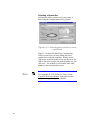
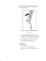
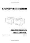
This chapter provides instructions on how to setup
and use your digital duplicator in applications
requiring spot color printing.
Figure 1-1.1. Spot color printing.
1
An Example Using
Adobe PageMaker
Step 1
The following steps will lead you through the process
of creating a four-pass color print using desktop
publishing software such as Adobe PageMaker.
Locate the page or document you wish to print and
open it in Adobe PageMaker. For our color page
example, we will use the picture shown in the Adobe
PageMaker file below.
Figure 1-1.2. Open Adobe PageMaker.
Step 2
2
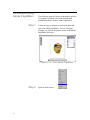
Open the Print screen.
Step 3
Enter the number of copies to be made.
Figure 1-1.3. Enter the number of copies to
be made.
Step 4
Select the
button.
Figure 1-1.4. Select the Color button.
3
Step 5
Activate the Separations feature.
Figure 1-1.5. Activate Separations.
Note: this step only needs to be done for the first
color.
Step 6
Perform the color selection process by turning off all
colors. Do this by selecting the
button.
Figure 1-1.6. Turn off all colors.
4
Step 7
Now select/highlight the ink color that matches the
drum you’ll be using (in our example, it will be
Cyan), then check the Print this ink box.
Figure 1-1.7. Select your ink color.
Figure 1-1.8. Enable printing for the color.
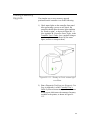
Step 8
Put the corresponding drum color into the duplicator,
and make sure the proper amount of paper is loaded
into the paper input tray.
Figure 1-1.9. Load the color drum into the
digital duplicator.
5
Step 9
Press the
color separation.
button to print the selected
Figure 1-1.10. Print the selected color.
Step 10
6
Repeat Steps 2 through 4, then 6 through 9 until all
four colors have been printed (CMYK).
2
PostScript Printing
Introduction
This chapter provides instructions on how to setup
and use your digital duplicator for printing PostScript
files. It includes information about:
q
PostScript Language
« PostScript Printer Drivers
« Memory Requirements
q
Typefaces
q
Troubleshooting
q
Generating a List of PostScript 3 Fonts Stored In
Your Controller
q
Related Documentation
7
PostScript Language
PostScript Printer
Drivers
The controller contains genuine PostScript Level 3
software from Adobe, which is backward compatible
with earlier versions of PostScript software.
To use software applications which support
PostScript, you must select a PostScript language
printer driver from within your application. For best
results, use the driver/PPD for your digital duplicator
installed during the Configuration Utility software
setup (see Chapter 2, Using Your Controller in the
Controller User’s Guide).
If, for some reason, that driver is not available (for
example, if you are using a version of Windows
earlier than Windows 95), you may use one of the
standard drivers that came with your operating system
or software, such as:
1. Apple LaserWriter II NT/NTX
2. HP LaserJet 4
3. Generic PostScript
If your software does not offer a PostScript language
printer driver selection, it may not support PostScript
printing. For more information, see your software
documentation or contact your software vendor.
Note
8
A file printed using the PostScript language may print
differently than in other printer languages because the
characters and spacing in your Adobe fonts may
differ. Differences that exist between PostScript
drivers can also cause this to happen.
Memory Requirements
The standard amount of memory which comes with
your controller is sufficient to handle the
requirements for PostScript printing.
9
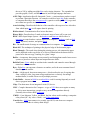
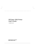
Typefaces
The PostScript 3 language contains 136 scalable
typefaces drawn from 40 typeface families, all
licensed from Adobe Systems, Inc. Many more
additional typefaces compatible with your controller
are available from the Adobe Type Library. These
typefaces can be purchased and used with your digital
duplicator.
Since PostScript typefaces require software support,
check your software documentation for information
about using PostScript typefaces.
Note
You should not use PostScript typefaces in
combination with PCL typefaces resident in your
controller or with other typefaces supported by PCL,
in the same document. Language switching allows
you to use either PostScript or PCL-supported type,
but not both simultaneously.
If you send a document with both PCL and PostScript
fonts, the controller will pick a printer language –
either PCL or PostScript – print the fonts native to it,
and interpret the others. Thus some fonts may not
print as expected.
For more information on Adobe typefaces available
for your software, point your Internet web browser to:
http://www.adobe.com
10
Figure 2-3.2.1. Internal PostScript 3 Typefaces, Page 1
11
Figure 2-3.2.2. Internal PostScript 3 Typefaces, Page 2
12
Adobe, the Adobe logo, Carta, PostScript, the
PostScript logo, and Tekton are registered trademarks
of Adobe Systems Incorporated. Macintosh,
TrueType, and Apple are trademarks of Apple
Computer, Inc. registered in the U.S. and other
countries. Apple Chancery, Chicago, Monaco, and
New York are trademarks of Apple Computer, Inc.
registered in the U.S. and other countries, used under
license. Geneva is a trademark of Apple Computer,
Inc., used under license. Microsoft and Windows are
registered trademarks of Microsoft Corporation in the
U.S. and other countries. Wingdings is either a
registered trademark or trademark of Microsoft
Corporation in the United States and or other
countries. Hoefler Text, Hoefler Text Italic, Hoefler
Text Black, Hoefler Text Black Italic and Hoefler
Text, Ornaments were designed by the Hoefler Type
Foundry. Times New Roman is a registered
trademark of the Monotype Corporation and may be
registered in certain jurisdictions. Albertus, Arial,
Gill Sans, Joanna, and Times New Roman are
trademarks of the Monotype Corporation and may be
registered in certain jurisdictions. Antique Olive is a
registered trademark of Marcel Olive. ITC Avant
Garde Gothic, ITC Bookman, ITC Lubalin Graph,
ITC Mona Lisa, ITC Zapf Chancery, and ITC Zapf
Dingbats are registered trademarks of International
Typeface Corporation. Eurostile is a trademark of
Nebiolo. *Helvetica, Optima, Palatino, Times, and
Univers are registered trademarks of Linotype-Hell
AG and/or its subsidiaries. Clarendon and Stempel
Garamond are trademarks of Linotype-Hell AG
and/or its subsidiaries. Marigold and Oxford are
trademarks of AlphaOmega Typography. Coronet is
a trademark of the Ludlow Type Foundry. Other
brand or product names are the trademarks or
registered trademarks of their respective holders.
13
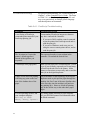
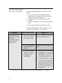
Troubleshooting
For general troubleshooting, see Troubleshooting in
Chapter 7, of the Controller User’s Guide. The items
in Table 2-4.1 are PostScript language-specific and
may occur particularly in multiple printer language
and shared printer environments.
Table 2-4.1. PostScript Troubleshooting
Condition
Recommended Action
A text listing of PostScript
commands prints instead of your
PostScript printing job.
A non-standard PostScript interpreter character
may have confused the controller.
•
•
14
If you are in DOS, send the control command
to put the printer into PostScript mode and resend the print job.
If you are in Windows, make sure you are
using the correct custom printer driver, and resend the print job.
The job prints in Courier (the
printer’s default typeface)
instead of the typeface you
requested.
The requested typeface is not resident in the
controller. Download the desired font.
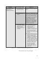
A PostScript error page prints.
Make sure the print job is a PostScript job. Check
to see if your software expected you to send setup
or PostScript header files to the printer. Make
whatever corrections are necessary and re-send the
print job to the digital duplicator.
A page set for bleed-off printing
is missing any print on the first
part of the leading edge of the
paper.
Due to the nature of the technology in the digital
duplicator used to pick/pull the paper through the
machine, the first 5 mm of the page (leading edge,
or the first edge into the machine) will not have
any printing on it. However, bleed-off printing
may be doe all the way to the other three paper
edges.
You are operating in DOS, and
your computer displays:
Writing to LPTn:
Abort, Retry, Ignore?
Try setting infinite timeouts on your computer.
See your MS-DOS manual for information about
the Mode command.
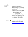
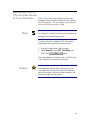
Generating a List of
PostScript 3 Fonts
Stored In Your
Controller
A list of PostScript 3 fonts available in your
controller for PostScript print jobs may be printed on
the digital duplicator using the Diagnostic Page
report. This list includes only permanent fonts stored
in the controller’s ROM.
To print a list of the controller’s PostScript 3 fonts on
the digital duplicator, perform the following steps:
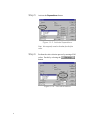
1. Start the Configuration Utility program.
2. Under Reports, select Diagnostic Page, and
click on the
button.
The digital duplicator will print the Diagnostic Page
report (which is the same as the Diagnostic Test Page,
obtained by pressing the Diagnostic Test Page button
on the rear of the controller chassis), which includes
the list of all PostScript 3 fonts in the controller’s
permanent font memory.
Caution
Generating this printout deletes all temporary soft
fonts (the fonts your software has downloaded for a
specific document). Because of this, temporary soft
fonts do not appear on the report.
15
Figure 2-5.1 Diagnostic Page sample report.
16
Related
Documentation
If you wish to learn more about the PostScript
language, the following books are available at book
stores or publishing houses.
PostScript Language Reference Manual: Second
Edition, Adobe Systems Incorporated. Menlo Park:
Addison-Wesley Publishing Company, Inc. ISBN 0201-181127-4
PostScript Language Tutorial and Cookbook, Adobe
Systems Incorporated. Menlo Park: Addison-Wesley
Publishing Company, Inc. ISBN 0-201-10179-3.
PostScript Language Program Design. Adobe
Systems Incorporated. Menlo Park: Addison-Wesley
Publishing Company, Inc., December 1988.
Learning PostScript: a Visual Approach, Ross Smith,
published by Peachpit Press. ISBN 0-938-151-12-6.
For more information on Adobe PostScript, point
your Internet web browser to:
http://www.adobe.com
17
18
3
PCL Printing
Introduction
This chapter provides instructions on how to use the
controller’s internal fonts that run under PCL. The
following topics are covered in this chapter:
q
Typefaces
« Microsoft DOS and Windows support
« Available type sizes
q
Intellifont and TrueType
« Intellifont
« TrueType
« Symbol Sets
« Selecting font features using PCL commands
q
Selecting Fonts
q
Default Font
q
Font Selection Priority
q
Generating a List of the PCL-5e Fonts Stored in
your Controller
q
Related Documentation
For information regarding the use of PostScript fonts,
see Chapter 2, PostScript Printing.
19
Typefaces
Microsoft DOS
Windows Support
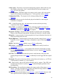
Your controller contains 45 internal scalable
typefaces and a 16.67-pitch bitmapped Line Printer
font. This broad selection of typefaces will support
most types of office documents, from spreadsheets
and reports to letters, presentations, and advertising
literature.
Whether your software runs under MSDOS or
Microsoft Windows, you can access any of the
internal typefaces, along with hundreds of accessory
typefaces available through third-party typeface
vendors.
Available Type Sizes
Depending upon the capabilities of your software,
you can size the proportionally spaced internal
typefaces from .25 point to 999.75 points, in quarterpoint increments.
Note
You should not use PostScript typefaces in
combination with PCL typefaces resident in your
controller or with other typefaces supported by PCL,
in the same document. Language switching allows
you to use either PostScript or PCL-supported type,
but not both simultaneously.
If you send a document with both PCL and PostScript
fonts, the controller will pick a printer language –
either PCL or PostScript – print the fonts native to it,
and interpret the others. Thus some fonts may not
print as expected.
20
Intellifont
Albertus
Albertus Extrabold
Antique Olive
Antique Olive Italic
Marigold
CG Omega
CG Omega Italic
CG Omega Bold
Antique Olive Bold
CG Omega Bold Italic
Clarendon Condensed
Coronet
Courier
Courier Italic
Courier Bold
Courier Bold Italic
Garamond Antiqua
Garamond Kursiv
Garamond Halbfett
Garamond Kursiv Halbfett
Letter Gothic
Letter Gothic Italic
Letter Gothic Bold
CG Times
CG Times Italic
CG Times Bold
CG Times Bold Italic
Univers Medium
Univers Medium Italic
Univers Bold
Univers Bold Italic
Univers Medium Condensed
Univers Medium Condensed Italic
Univers Bold Condensed
Univers Bold Condensed Italic
Line Printer (16.67 pitch, 8.5 point only)
TrueType
Arial
Arial Italic
Times New Roman
Arial Bold
Arial Bold Italic
Times New Roman Bold
Times New Roman Bold Italic
Symbol αβχ∆ΕΦΓ
Wingdings abcdefg
Times New Roman Italic
Figure 3-2.1. Internal PCL-5e Typefaces
21
Intellifont and
TrueType
22
In your controller, the Intellifont and TrueType font
scaling technologies both run under PLC-5e, giving
you rapid font scaling inside the controller itself.
Intellifont
Intellifont is a font scaling technology developed by
the AGFA division of Miles Inc. It is used on many
scalable printers, including the digital duplicator
controller. Most software packages support them,
including Microsoft Windows and Corel WordPerfect
applications.
TrueType
TrueType is a font scaling technology developed by
the Microsoft Corporation and Apple Computer, Inc.
Your controller has 14 internal typefaces that match
the TrueType typefaces included with Microsoft
Windows. This enhances Windows’ printing
performance and quality, because Windows
applications do not have to download these typefaces
to the controller.
Note
You can access both Intellifont and TrueType type
scaling technologies through Microsoft Windows and
other applications.
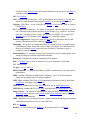
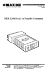
Symbol Sets
A “symbol set” or “character set” (see Figure 3-3.3) is
a collection of letters, numbers, and symbols designed
for specific applications such as scientific equations,
legal citations, and international languages.
Figure 3-3.3. Roman-8 and PC-8 Symbol Sets
23
Selecting a Symbol Set
Selecting the active symbol set for your printer is
done using the Configuration Utility program.
Figure 3-3.4. Selecting the controller’s active
symbol set.
Figure 3-3.4 shows the area of the Configuration
Utility screen where you may change the active
symbol set used by the controller. Simply use the
right arrow to pull down the screen, use the bar to the
right of the list to scroll to the desired symbol set, and
click on it. The symbol set will remain active until
another is selected using this screen.
Note
24
See Appendix D, PCL Symbol Set Tables, in the
Controller Reference Manual, for details as to the
symbol sets supported by the controller.
Software Symbol Set Availability
There are two things you should know about symbol
set availability:
1. Your software may support all of your
controller’s symbol sets, or just a few of them.
Refer to your software documentation for more
information on what symbol sets, character sets,
or code pages it supports.
2. Typefaces are designed to work with specific
symbol sets. For example, the Arial typeface
design does not include characters to support the
Math-8 symbol set.
Refer to Appendix D, PCL Symbol Sets, in this
manual to see which symbol sets work with the
typefaces you are using.
Entering Symbols into Text
If you want to print a symbol such as infinity ( ∞ ),
you must first select the symbol set that contains that
character.
For example, the ∞ sign is character #236 in the PC-8
symbol set (see Appendix D, PCL Symbol Sets).
Your software documentation will contain
instructions for entering special symbols into your
text. Look in the software documentation’s index for
phrases such as “compose feature”, “composite
characters,” “symbol sets,” “character sets,” “code
pages,” or “extended characters.”
25
Selecting font features
using PCL codes
26
If you are writing programs or using software that
requires you to enter PCL codes to select fonts or font
characteristics, you can find the PCL codes for
selecting fonts in any typeface reference guide. Also,
refer to the items listed in the Related Documentation
section of this chapter.
Selecting Fonts
Fonts are selected through the software you are using.
Look in your software documentation for topics such
as “font selection,” “base font,” “printer setup,” “print
options’” “font appearance’” “change font,” or “select
type.”
Default Font
The default PCL font in the printer is 10 pitch
Courier with the Roman-8 symbol set. The printer
uses this font unless your software sends (or you
manually send) a printer font selection command to
request a font in place of the default.
27
Font Selection
Priority
In PCL mode, if both a scalable typeface and a
bitmapped typeface are available from the same
source, the selection criteria applied depends upon the
dpi print resolution of the digital duplicator:
1. For 600 dpi digital duplicators:
a. 600 dpi bitmapped font
b. scalable font
c. 300 dpi bitmapped font
2. For 400 dpi digital duplicators:
a. 400 dpi bitmapped font
b. scalable font
c. 300 dpi bitmapped font
3. For 300 dpi digital duplicators:
a. 300 dpi bitmapped font
b. scalable font
28
Generating a List of
PCL-5e Fonts Stored
In Your Controller
Note
The PCL Test Page report lists the typefaces and
bitmapped fonts currently available in your controller
for PCL print jobs. This list includes only permanent
fonts stored in the controller’s ROM.
See Chapter 2, PostScript Printing, for instructions on
printing a list of PostScript typefaces.
To print a list of the controller’s PCL fonts on the
digital duplicator, perform the following steps:
3. Start the Configuration Utility program.
4. Under Reports, select PCL Test Page, and
click on the
button.
The digital duplicator will print a list of all PCL fonts
in the controller’s permanent font memory.
Caution
Generating this printout deletes all temporary soft
fonts (the fonts your software has downloaded for a
specific document). Because of this, temporary soft
fonts do not appear on the report.
29
Figure 3-7.1 PCL Test Page sample report.
30
Related
Documentation
If you wish to learn more about PCL, HP-GL/2, or
PJL, order the Technical Reference Manual bundle
for an HP LaserJet printer from the Hewlett Packard
Company. The HP part number (as of 6/17/97) for
the Technical Reference Manual bundle is:
5021-0377
The documentation includes:
•
•
•
•
PCL 5/HP-GL/2 Technical Reference Manual
PJL Technical Reference Manual
PCL 5 Comparison Guide
PCL 5 Quick Reference Guide
The documentation package may be obtained by
telephoning HP Parts Direct at 1 800 227 8164 (US).
In other countries, contact your local HP office.
For additional information, point your Internet web
browser to:
http://www.hp.com/
31
32
A
Controller I/O Port Specifications
Introduction
This appendix provides information about connecting
your controller to your computer. Your controller
supports connection to a computer for printing from a
bi-directional parallel/ECP interface (PC), a
LocalTalk interface (Mac), and a Local Area Network
interface.
This appendix contains the following information:
q
Configuring Your Printer
q
Parallel Port Connection
« IEEE 1284 Parallel Port Characteristics
« IEEE 1284 Port Pinout
« MSDOS Commands for Parallel Port Use
q
LocalTalk Connection
« LocalTalk Port Characteristics
« LocalTalk Port Pinout
q
Local Area Network Connection
« LAN Port Characteristics
« LAN Port Pinout
q
Caution
Controller ⇔ Digital Duplicator Cable
Specifications
Proper Grounding: Ensure that all interface cables
and host computer(s) or other equipment attached to
the controller follow proper grounding methods for
electronic equipment in accordance with local
electrical codes.
33
Parallel Port
Connection
Connecting to the parallel interface is generally the
fastest method of sending data to your controller. It is
probably the best choice especially if you use many
soft fonts in your document, or if you print complex
graphics.
The high-performance parallel input/output port on
the controller utilizes the IEEE 1284 – 1994 design,
supporting hardware-enhanced, nibble-mode reversedirection data transfer, for high-speed communication
between the computer and controller. Be sure to use
a cable conforming to this design standard to realize
the full data speed benefit from this interface.
IEEE 1284 Parallel Port
Characteristics
Maximum data speed: 2 MBytes/sec.
Maximum cable length: 10 meters (30 feet).
Chassis connector type: IEEE 1284 Type C (MiniCentronics).
Design standard:
Note
IEEE 1284 – 1994.
To use this interface, the parallel port (e.g., LPT1:) on
your computer must be configured as an ECP (not
EPP) Printer Port.
For more information on the parallel port, point your
Internet web browser to:
http://www.fapo.com/ieee1284.htm
34
IEEE 1284 Parallel Port
Pinout
Computer End
1284A Connector
Pin
1
18
2
19
3
19
4
20
5
20
6
21
7
2
8
22
9
22
10
24
11
23
12
24
13
24
14
25
15
23
16
25
17
25
(nc)
(nc)
Signal
nStrobe
Rtn
Data_1
Rtn
Data_2
Rtn
Data_3
Rtn
Data_4
Rtn
Data_5
Rtn
Data_6
Rtn
Data_7
Rtn
Data_8
Rtn
nAck
Rtn
Busy
Rtn
PE
Rtn
Select
Rtn
nAutoFeed
Rtn
nFault
Rtn
nInit
Rtn
nSelectIn
Rtn
+5V/Host_Avail
Perph_Avail
Controller End
1284C Connector
Pin
15
33
6
24
7
25
8
26
9
27
10
28
11
29
12
30
13
31
3
21
1
19
5
23
2
20
17
35
4
22
14
32
16
34
18
36
Table A-2.1. IEEE 1284 A-to-C Connector Contact Numbering
35
MSDOS Commands for
Parallel Port Use
In the MSDOS environment, most personal
computers default to a parallel printer port for
printing. To ensure that your computer is sending
information to your parallel printer port, type the
following MS-DOS command at your MS-DOS
prompt or include it in your AUTOEXEC.BAT file:
MODE LPT:,,P
For MS-DOS version 4.0 and above, enter:
MODE LPT:,,B
Note
36
This example assumes that your are using parallel
printer port LPT1. If you are using LPT2 or LPT3,
replace LPT1 in the example with the printer port that
you are using.
LocalTalk
Connection
LocalTalk Port
Characteristics
The LocalTalk interface is used by the Macintosh
series of computers designed and built by Apple
Computer, Inc. It is a bi-directional port and supports
the AppleTalk local area network (LAN) protocol.
Maximum data speed:
230.4Kbs / 28.8KBytes/sec.
Maximum cable length: 300 meters (1000 feet).
Chassis connector type: 8-pin mini-DIN female.
Design standard:
Apple proprietary.
For more information on AppleTalk and LocalTalk,
point your Internet web browser to:
http://www.cisco.com/univercd/cc/td/doc/cisintwk/ito
_doc/55142.htm
- or http://www.apple.com
37
LocalTalk Port
Pinout
Contact Number
Signal Name
1
(not connected)
2
(not connected)
3
- Data Out
4
Ground
5
- Data In
6
+ Data Out
7
(not connected)
8
+ Data In
Table A-4.1. LocalTalk Connector Contact
Numbering.
38
Local Area Network
Connection
The Local Area Network Port provides an interface to
an Ethernet, 10BASE-T LAN.
Refer to Using the Local Area Network Port in
Chapter 2, Using Your Printer, of the Controller
User’s Guide for instructions on using this interface.
Local Area Network
Port Characteristics
Maximum data speed: 10 Mbps.
Maximum cable length: 100 meters (300 feet), UTP
cable.
Chassis connector type: RJ-45.
Design standard:
Ethernet.
IEEE 802.3i, 10BASE-T
Local Area Network
Port Pinout
I/O Pin #
UTP Wire color
Ethernet Signal Name
1
brown
Transmit +
2
brown/white
Transmit -
3
orange
Receive +
4
green
5
green/white
6
orange/white
7
blue
8
blue/white
Receive -
Figure A-5.1. Local Area Network Port Connector Contact Numbering
39
Controller ⇔ Digital
Duplicator Cable
Specifications
Caution
Compatibility
The cable connecting the controller to the digital
duplicator has been constructed to provide the highest
image quality to your digital duplicator.
A 10-ft (3 m) cable has been provided with your
controller and is the recommended cable to be used
for this purpose. Use of a cable other than the one
supplied with your controller may adversely affect the
image quality received and printed by your digital
duplicator.
Max. Cable length:
3 meters (10 feet).
Chassis connector types:
Controller:
IEEE 1284 Type A, Male
(DB25M).
40
Digital Duplicator:
IEEE 1284 Type A, Female
(DB25F).
Design standard:
IEEE 1284 – 1994.
B
Upgrading Controller Memory
Introduction
This appendix covers:
q
Memory (SIMM) Board Installation.
q
Testing a Memory Upgrade.
q
Troubleshooting a Memory Upgrade.
The controller has two SIMM (Single In-line Memory
Module) slots. Use them to install additional printer
memory. The controller may have up to 256 Mbytes
of memory installed.
To be sure of compatibility with your controller,
purchase SIMM boards from the authorized supplier
of supplies and options for your model of controller.
Caution
Unauthorized installation or upgrading of memory
will void your warranty.
If you have any questions, call your local sales or
service representative for the digital duplicator or
controller.
41
Memory (SIMM)
Board Installation
Note
Follow these instructions to install memory SIMM
boards. Always install SIMM boards in the same
manner.
The following general guidelines apply to installing
memory in the controller.
1) The controller must have at least the minimum/
standard amount of memory installed, as specified
under the Printer Features section of the
Controller User’s Guide in order to function
correctly.
2) The controller must have a SIMM board installed
in slot 1.
Outline for Memory Upgrades
1. Remove any existing/already installed SIMMs.
2. Install existing and new SIMMs per the SIMM-slot placement rules.
SIMM-slot placement rules.
Case 1 – After removing any existing SIMM(s), a
total of one SIMM is to be installed.
This situation would occur if, for example, you were
to replace a partially- or non-functioning SIMM with
a new one. In this situation, simply substitute a new
SIMM for the existing one, using only slot 1. The new
SIMM must meet or exceed the minimum memory
requirements for your controller. For the sake of
future upgrade compatibility, if the new SIMM is of
the single-sided configuration (see figure B-1.1), it
should have a PD (Presence Detect) jumper installed.
42
Case 2 – After removing any existing SIMM(s),
two SIMMs are to be installed, at least one of
which is a double-sided SIMM (see figure B-1.2).
In this configuration, the double-sided SIMM board
must be installed into slot 1. This is regardless of
respective memory sizes of the SIMM boards – the
double-sided board always goes into slot 1. If both
SIMMs are double-sided, it does not matter which
one goes into which slot.
Case 3 – After removing any existing SIMM(s),
two single-sided SIMMs are to be installed (see
figures B-1.1).
This configuration could occur if, for example, you
wanted to simply add a second SIMM to the
controller’s factory-shipped configuration. In this
case, the single-sided SIMM to be installed into slot 2
must have a PD jumper installed.
Unsupported Memory Configurations
Memory configurations not listed under the rules
above are not supported, or will not yield the correct
amount of memory for the controller. This includes
any combination of boards which:
1) Does not yield the minimum amount of memory
needed by the controller.
2) Utilizes 1 or 2 Mbyte SIMMs.
3) Utilizes a single-sided SIMM in slot 2 that does
not have a PD jumper installed.
If you believe your memory configuration is
supported, but it is not yielding the correct amount of
memory, see the section on Troubleshooting a
Memory Upgrade located at the end of this Appendix.
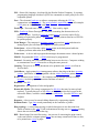
43
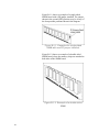
Figure B-1.1 shows an example of a single-sided
SIMM board with a PD jumper installed. The jumper,
shown in the second (PD2) position, may be in any of
the four possible positions shown in the diagram.
Figure B-1.1. Example of a single-sided
SIMM with one PD jumper installed.
Figure B-1.2 shows an example of a double-sided
SIMM board, where the memory chips are attached to
both sides of the SIMM board.
Figure B-1.2. Example of a double-sided
SIMM.
44
Note
All memory boards used in upgrading the memory
configuration of the controller must adhere to the
JEDEC standards for 72-pin SIMMs. Single-sided
SIMMs placed in slot 2 must have at least one of the
Presence Detect jumpers in place: PD1, PD2, PD3,
or PD4.
For more information, locate JEDEC Standard No.
21-C, pp. 4.4.2-1 through 4.4.2-16. A copy of these
pages may be obtained by searching the following
web site:
http://www.jedec.org.
45
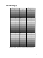
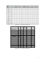
Table B-1.1 is provided as a guide when upgrading
memory.
It is recommended that memory be upgraded only in
the configurations shown.
Total Controller Memory
8
12
16
16
20
24
32
32
36
40
40
48
64
64
68
68
72
80
96
128
128
132
136
144
160
196
256
MBytes
MBytes
MBytes
MBytes
MBytes
MBytes
MBytes
MBytes
MBytes
MBytes
MBytes
MBytes
MBytes
MBytes
MBytes
MBytes
MBytes
MBytes
MBytes
MBytes
MBytes
MBytes
MBytes
MBytes
MBytes
MBytes
MBytes
Slot 1
8
8
8
16
16
8
16
32
32
32
8
32
32
64
64
4
8
16
32
64
128
128
128
128
128
128
128
MByte
MByte
MByte
MByte
MByte
MByte
MByte
MByte
MByte
MByte
MByte
MByte
MByte
MByte
MByte
MByte
MByte
MByte
MByte
MByte
MByte
MByte
MByte
MByte
MByte
MByte
MByte
SIMM ds
SIMM ds
SIMM ds
SIMM
SIMM
SIMM ds
SIMM
SIMM
SIMM ds
SIMM ds
SIMM ds
SIMM ds
SIMM ds
SIMM
SIMM
SIMM
SIMM ds
SIMM
SIMM ds
SIMM
SIMM ds
SIMM ds
SIMM ds
SIMM ds
SIMM ds
SIMM ds
SIMM ds
Slot 2
4
8
4
16
16
4
8
32
16
32
4
64
64
64
64
64
4
8
16
32
64
128
(empty)
MByte SIMM
MByte SIMM ds
(empty)
MByte SIMM ssj
MByte SIMM
MByte SIMM ssj
(empty)
MByte SIMM
MByte SIMM ds
MByte SIMM ds
MByte SIMM
MByte SIMM ds
(empty)
MByte SIMM ssj
MByte SIMM ssj
MByte SIMM
MByte SIMM ssj
MByte SIMM
MByte SIMM ssj
(empty)
MByte SIMM
MByte SIMM
MByte SIMM
MByte SIMM ds
MByte SIMM
MByte SIMM ds
Notes:
ds – Typically, the configuration of this SIMM is double-sided.
ssj – In single-sided configuration, this SIMM must have the PD jumper installed for the memory upgrade
to function correctly.
Table B-1.1. Supported memory configurations.
46
Protecting the SIMM
Board
SIMM boards can be easily damaged by small
amounts of static electricity. To remove any static
electricity from your body:
F Touch the surface of the antistatic package before
removing the board from its package. When
handling the board, frequently touch bare metal
on the printer or the antistatic bag or wear an
antistatic wrist strap.
F Avoid moving about the work area to prevent
generating static electricity.
F Handle the board carefully at all times.
Avoid
flexing it or touching its components.
Caution
When removing a board from the antistatic package,
avoid touching the metal traces on the SIMM board
through handling only by the edges.
47
Installation
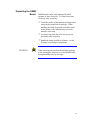
Warning
The following section describes procedures to remove
the controller’s top cover and insert a SIMM board.
Hazardous voltages are present in the printer
controller. Never remove any cover or work
near exposed electrical parts while the power
cord is connected.
Accessing the SIMM Slots.
1. Switch the controller OFF
2. Unplug the power cord from the controller.
3. Position the controller so the right side is facing
you.
4. Place the antistatic bag containing the SIMM
board(s) near the controller.
5. Use a Phillips #2 screwdriver to remove the four
screws holding the top cover to the chassis.
Figure B-1.3. Removing top cover hold-down
screws.
48
6. Remove the top cover from the chassis.
Figure B-1.4. Removing top cover.
7. Locate the memory SIMM memory slots. Note
the location of slot 1. If only one SIMM is
present, it is always located in slot 1.
Figure B-1.5. Locating SIMM slot 1.
49
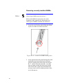
Removing currently installed SIMMs.
Note
Always begin SIMM removal with slot 1.
Refer to the SIMM-slot placement rules at the
beginning of this Appendix for information as to
which type of SIMM is installed into which slot.
1. Locate the metal locking tabs holding the SIMM
in place on either side of the board slot.
Figure B-1.6. Locate the SIMM locking tabs.
2. Gently push down on the metal locking tabs while
rotating the board toward the back of the slot shown as rotating down and to the left in Figure
B-1.7 - until it clears the metal tabs. As it may
take two hands to hold down the metal locking
tabs on both sides of the board simultaneously,
you may want to call for another person to assist
you in this process.
50
Figure B-1.7. Removing an existing SIMM
board.
3. Remove the existing SIMM and place into an
antistatic bag.
51
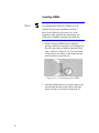
Installing SIMMs.
Note
For configurations where two SIMMs are to be
installed, always begin installation with slot 2.
Refer to the SIMM-slot placement rules at the
beginning of this Appendix for information as to
which type of SIMM is installed into which slot.
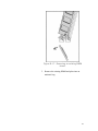
1. Remove the new SIMM from its antistatic
package. Hold the board with your forefingers on
the side edges and your thumbs against the back
edge, as shown in Figure B-1.8. Turn the board
so the notch on one end is on the bottom and the
metal teeth face toward the slot.
Figure B-1.8. Positioning the SIMM.
2. Hold the SIMM board at a 30-degree angle to the
slot and push the edge of the board evenly and
firmly into the slot, as shown in Figure B-1.9.
52
Figure B-1.9. Seating the SIMM board in the
socket.
53
Rotate the board to the right until the board ‘clicks’
into the metal locking tabs, securing the board in
place - see Figure B-1.10.
Figure B-1.10. Securing the SIMM board in
the socket.
3. Gently rock the SIMM back and forth. If it is
seated correctly, it will not lift away from the slot.
If it lifts up, you have not pushed it firmly enough
into the slot, and you must try installing again.
4. If another SIMM is to be installed (i.e., slot 1),
simply repeat these installation steps.
Finishing up
1. Replace the top cover.
2. Replace the top cover hold down screws.
3. Plug in the power cord and switch the controller
ON.
54
Testing a Memory
Upgrade
The simplest way to test a memory upgrade
performed on the controller is to do the following:
1) Check status lights on the controller front panel.
After performing a power-on self check, the
controller should show the status light condition
for “Ready to print”, as shown in Figure B-1.11.
(See Appendix B, Controller Status Lights, in the
Controller User’s Guide, for a complete listing as
to what conditions are indicated by the status
lights, and how to interpret them.)
Figure B-1.11. ‘Ready to Print’ status light
condition.
2) Print a Diagnostic Test Page (see Diagnostic Test
Page in Appendix A of the Controller User’s
Guide if you need instructions), and note the area
on the report which states the amount of memory
available to the printer, as shown in Figure B1.12.
55
Figure B-1.12. Using the Diagnostic Test Page to verify correct memory
installation.
Printing this page verifies that the
a) controller is able to communicate with the
digital duplicator,
b) memory installation was done correctly,
c) amount of memory you installed is what you
expected, and
d) memory is functioning correctly.
56
If the test page does not indicate the correct amount
of memory, or there is some other problem, proceed
with the next section (troubleshooting).
57
Troubleshooting a
Memory Upgrade
A memory upgrade/installation can fail for several
reasons:
1) In a two-memory-board installation, a singlesided memory card has been installed into slot 1
that does not have a PD jumper.
2) A memory board is not seated properly when
installed.
3) Memory is installed correctly but is of insufficient
size.
4) One or both of the memory boards has failed.
Check the following tables for the symptom you are
experiencing to identify a course of action.
Symptom
Most Probable Causes
What to do
The Diagnostic Test
Page indicates that the
controller is
recognizing memory,
but it is not of the
expected size.
1) The SIMM installed in
slot 1 is not a doublesided memory card.
Procure a SIMM that is doublesided and install into slot 1.
2) The SIMM installed in
slot 2 is not seated
properly
Properly re-install the SIMM in
slot 2.
3) The installed SIMM(s)
has (have) a memory
size that is actually
smaller than it’s
specification.
a) Check to make sure the board
part numbers are correct for
the SIMM size. If not, obtain
and install the correct ones
for the desired memory size.
b) The SIMM could have a fault
in which it only reports part
(for example, one-half) of the
memory for which it is rated.
In this case, the board must
be returned to the vendor for
replacement.
Table B-1.2. Troubleshooting – Incorrect Diagnostic Test Page.
58
Symptom
Most Probable Causes
What to do
The controller status
lights indicate a
controller unit failure.
1) The SIMM in slot 1 is
not seated correctly.
Properly re-install the SIMM in
slot 1.
2) The SIMM in slot 1 is
at fault.
If you have a SIMM in slot 2 and
it has a memory size sufficiently
large for the standard memory
requirements of your controller,
try installing it in the slot 1
position. If the controller
responds positively to this, you
probably have a faulty SIMM,
which must be returned to the
vendor for replacement.
3) Total memory being
reported is less than the
standard memory
configuration for your
controller.
a) The combination of SIMMs
yields a size under the
standard memory
configuration for your
controller. You must install
the minimum amount of
memory so the controller will
function.
b) SIMMs in either slot do not
report the correct amount of
memory available to the
controller. Try swapping the
SIMMs from slot 1 to 2 to
see if the controller will give
a ‘ready to print’ status. If it
will not, and you are sure the
SIMMs are of the correct
size, they are probably
defective and must be
returned to the vendor for
replacement.
Table B-1.3. Troubleshooting - status light problem.
If the problems persist, call your supplier.
59
60
C
Font Basics
Introduction
This appendix contains basic information about fonts.
The following topics are covered:
q
Elements of a Font
q
Screen Fonts for Windows
q
Selecting Fonts
q
Default Font
q
Considerations For Shared Printer Environments
q
Font Selection Priority
61
Elements of a Font
Typeface
When you select a typeface through your word
processing program or other software, you may be
prompted to select a point size or pitch. When you
set up your page layout, you will also choose whether
the text will be in portrait or landscape orientation.
This combination of a typeface, a specific point size,
and an orientation is called a “font”.
A “typeface” is the name for a specific design of
characters and symbols. For example, “Times New
Roman” is one typeface and “Times New Roman
Bold Italic” is another typeface (see Figure C-2.1).
Both those typefaces belong to the Times New
Roman typeface “family”.
Times New Roman
Times New Roman Bold
Times New Roman Italic
Times New Roman Bold Italic
Figure C-2.1. Four Typefaces from the Times
New Roman Family
Note
62
When you make a bold or italic, you are actually
telling the software to select a different typeface.
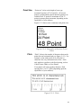
Point Size
“Point size” refers to the height of your type
measured in points (1/72 of an inch). All of your
printer’s proportionally spaced internal typefaces are
scalable from .25 point to a maximum of 999.75
points in quarter-point increments, depending on the
capabilities of your software.
Figure C-2.2 shows some commonly used point sizes.
8 Point
10 Point
12 Point
14 Point
18 Point
24 Point
48 Point
Figure C-2.2. Examples of Various Point
Sizes
Pitch
“Pitch” refers to the number of characters that can be
printed in one horizontal inch (see Figure C-2.3). For
example, a font with a pitch of 10 will print 10
characters for every horizontal inch of text. Pitch
only applies to typefaces with fixed spacing, such as
Courier, letter Gothic, or Line Printer.
Your printer will scale typefaces that have fixed
spacing from .5 to 85.7 pitch (depending upon the
capabilities of your software).
Figure C-2.3. Pitch
63
Orientation
Portrait orientation is vertical – see Figure C-2.4, Item
1. Landscape orientation is horizontal – see Figure C2.4, Item 2. When the printer receives a software
command to print in landscape orientation, it will
automatically rotate any internal and accessory font to
print along the wide edge of your paper (landscape
mode).
Figure C-2.4. Portrait and Landscape
Orientations
Other Font
Characteristics
64
A font has other characteristics such as stroke,
weight, style, and spacing (proportional or fixedpitch). Your software will probably not ask you to
enter codes for these font characteristics.
Screen Fonts for
Windows
To achieve true WYSIWYG (“what you see is what
you get”) capability for software running under
Microsoft Windows, you must have screen fonts that
match your printer fonts.
65
Selecting Fonts
Fonts are selected through the software you are using.
Look in your software documentation for topics such
as “font selection,” “base font,” “printer setup,” “print
options”, “font appearance”, “change font,” or “select
type.”
Here are a couple of simple rules to remember
regarding font selection:
1) Do not mix PCL and PostScript fonts in the same
document. The controller must switch
personalities in order to print one font versus the
other, and it cannot do this halfway through a
print job. Instead, it will try to substitute a
suitable PCL font for the PostScript font being
called for, or vice-versa, and your document will
not look right when printed. For this reason, you
should use all PCL or all PostScript fonts in a
single document
2) Be sure to use the correct printer driver for the
fonts you are using – either PCL or PostScript.
Default Font
66
The default font depends upon the printer language/
driver you are using. If you are using PCL, look
under Default Font in Chapter 3, PCL Printing, in
this manual. If you are using PostScript, look under
Default Font in Chapter 2, PostScript Printing, in this
manual.
Considerations for
Shared Printer
Environments
Your digital duplicator may be connected to other
computers besides yours. This is done one of several
ways:
1. Two computers may use the digital duplicator
simultaneously using either of the two direct
connection interfaces on the back of the controller
(parallel or LocalTalk).
2. Your organization may be using a switch box to
connect two or more computers, one at a time, to
the digital duplicator.
3. The controller may be connected to a LAN,
providing access to the digital duplicator to any
number of users.
A combination of any of the above three methods.
Be sure to check with the other users of the digital
duplicator before you download or remove soft fonts
and typefaces. This will conserve memory and help
you avoid unexpected printer output.
67
Font Selection
Priority
This is the order in which your controller selects its
fonts:
1. First, the controller looks for a downloaded soft
font.
2. If the requested font is not available as a diskbased font (“soft font”), the controller checks for
fonts in its memory (SIMM).
3. If the font is not available in it’s memory, the
controller selects one of its internal fonts.
When choosing a font, the font must be available
from one of the above sources. If the font you request
is not available, the controller selects the closest
match based on individual font characteristics.
68
D
PCL Symbol Sets
Introduction
Symbol sets are unique groupings of characters
(alphabetic, numeric, punctuation, and special
symbols) designed to meet the requirements of
specific languages and occupations. To help you
choose and use the proper symbol set, this appendix
contains:
q
Tables showing which symbol sets are supported
by each of the controller’s internal typefaces.
q
Substitution table for accessing ISO symbols from
the Roman-8 symbol set.
For information as to the characters available in each
of the symbol sets, see the Related Documentation
section of the Chapter 3, PCL Printing, in this
Controller Reference Manual.
Note
For PostScript symbol sets, see your software
documentation. For general information, see Chapter
2, PostScript Printing, in this manual
69
Software Support
Although all the characters and symbols shown on the
tables are printable, your software might not support
some of them. Check your software documentation
to see which symbol sets are supported. Look for
phrases such as “code pages,” “extended characters,”
and “character sets.”
Typeface Support
Typefaces are designed to include limited
combinations of characters and symbols. Some
typefaces, such as Wingdings, support only one
specific symbol set. Other typefaces, such as CG
Times and Univers, support almost all of the
controller’s available symbol sets.
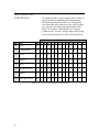
Use Table D-2.1 and Table D-2.2 to determine which
symbol sets to use with the typefaces you have
chosen. These tables also contain information to help
you select symbol sets through your software
application using PCL commands.
Note
70
Symbol sets other than those described here are
available with various software products, such as
word processors, spreadsheets, and desktop
publishing programs.
Table D-2.1. Intellifont Symbol Sets
Configuration Utility
Symbol Set Name
ID
Arial
Times
New
Roman
Desktop
ISO 8859-1 Latin 1
Legal
Math-8
MS Publishing
PC-8
PC-8 D/N
PC-850
Pi Font
PS Math
PS Text
Roman-8
Ventura Int’l
Ventura Math
Ventura US
Windows 3.0 Latin 1
Symbol
Wingdings
7J
0N
1U
8M
6J
10U
11U
12U
15U
5M
10J
8U
13J
6M
14J
9U
19M
579L
ü
ü
ü
ü
ü
ü
ü
ü
ü
ü
ü
ü
ü
ü
ü
ü
ü
ü
ü
ü
ü
ü
Wingdings
Symbol
ü
ü
Table D-2.2. TrueType Symbol Sets
71
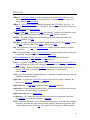
ISO Symbol Set
Substitution
This table provides a quick reference for the values of
special characters contained in ISO (International
Standards Organization) symbol sets. ISO symbol
sets contain the same characters as the ASCII symbol
set, except for the character positions listed in this
table. For example, within the ISO 21 (German)
symbol set, the “section” sign (§) replaces the @ sign
used in decimal position 64 of the ASCII symbol set.
Decimal Character Equivalents
91 92 93 94 96 123 124
ISO
Name
ID
35
36
64
125
126
6
ASCII
0U
#
$
@
[
\
]
ˆ
‘
{
|
}
~
4
United Kingdom
1E
£
$
@
[
\
]
^
`
{
|
}
¯
69
French
1F
£
$
´
°
¸
§
^
µ
¾
ù
À
“
21
German
1G
#
$
§
ƒ
š
¥
^
`
¬
Ø
ò
¢
15
Italian
0I
£
$
§
º
¸
¾
^
ù
´
à
À
Ò
11
Swedish for Names
0S
#
¤
‹
ƒ
š
•
¥
¾
¬
Ø
¯
ò
17
Spanish
2S
£
$
§
¡
N
¿
^
`
°
Ô
¸
~
60
Norwegian version 1
0D
#
$
@
€
•
•
^
`
³
ø
¯
¯
Table D-4.1. ISO Substitution Characters
72
Glossary
10Base-2 - IEEE 802.3 Ethernet standard implemented on thin coaxial (RG58) cable,
where 10 = 10 Mbps transmission rate and Base = baseband. May have up to 185
meters between network nodes.
10Base-T - IEEE 802.3 Ethernet standard implemented on UTP cable, where 10 = 10
Mbps transmission rate and Base = baseband. May have up to 100 meters between a
network node and a network drop.
25 MHz vs 100 MHz - These refer to CPU clock speeds. Generally, the higher the clock
speed, the faster the computational speed of the CPU, and the computer.
300 DPI - A printer resolution specification stating that the length and width of the
master will have 300 DPI.
300x400 - A printer resolution specification stating that the length of the master will have
300 DPI, while the width of the master will have 400 DPI.
386 - First-generation 32-bit x86 microprocessor introduced to the market by the Intel
Corporation.
486 - Second-generation 32-bit x86 microprocessor introduced to the market by the Intel
Corporation, incorporating a dedicated math coprocessor.
64 Bit Architecture - A CPU, memory, and I/O system that transfers data and
instructions using an 8 byte-at-a-time (64 bits) process.
Adobe - A software company that produces the PostScript printer drivers and PostScript
fonts and language used by your computer to communicate with the controller.
Adobe Certified - Indicates that the hardware or software has passed a rigorous set of
tests by Adobe and is certified to perform printing tasks as stated by the
manufacturer.
ANSI - American National Standards Institute – a standards committee that develops and
publishes technical standards.
AppleTalk - A proprietary network layer protocol developed by Apple Computer, Inc.
for use in its Macintosh series of computers.
AppleTalk Port - An I/O port that adheres to the AppleTalk standard.
Application - Computer programs which allow computer users to perform some specific
task such as word processing, accounting, etc.
Application software - See Application.
Architecture - The design and implementation of connecting components, interfaces,
and protocols in a computer, program, or network.
ASCII - American Standard Code for Information Interchange - A standard for encoding
characters (including the upper and lowercase alphabet, numerals, punctuation, and
control character) using seven bits. The standard is 128 characters; IBM expanded
73
the set to 256 by adding an eighth bit to each existing character. The expanded set
provides graphic, Greek, scientific, financial, and foreign language characters.
ASIC Chip - Application-Specific Integrated Circuit – a semiconductor product created
to perform a particular function. An example would be a logic chip in the controller
or computer that allows the microprocessor (a generic or non-specific IC), to get and
move data in a specific environment.
Auto Switching - Describes the behavior of the controller with respect to how it decides
from which input port it will capture data for printing.
Bi-directional - Communication flow in two directions.
Binary Digit - Describes base-2 math or electronic states of zero (off) or one (on).
BIOS - Basic Input Output System – the hardware and firmware which allows a
processor to control and use various aspects of a computer’s hardware (such as disk
drives, keyboard, monitor, and printer ports).
Bit - The smallest unit of storage or communication in a computer. See Binary Digit.
Bleed Off - The technique of printing to the physical edge of the document paper.
Bleed Through - The result when, during the printing process, ink saturates the paper
and is deposited on the copy below it, or leaves residual ink on the drum which is
passed on to the next copy, resulting in a ‘ghost’ image.
Buffer - A temporary data storage area necessarily used during data transfer between two
systems or processes whose input and output data rates differ.
Built-In Fonts - Fonts which are resident in the controller and cannot be erased through
normal use of the controller.
Byte - Eight bits, can represent a character or number, and is the most common form of
data storage and transfer.
Cache – A high-speed, short-term storage area. Also describes the act of copying data
from a relatively slow, long-term storage medium into a relatively fast storage
medium/buffer, to enable fast access by multiple processes.
Cache Buffer - An area in RAM or on a hard drive used for storing frequently accessed
data or program instructions.
Chip - The short name for an integrated circuit (IC) device.
CISC - Complex Instruction Set Computer – a type of CPU that can recognize as many
as 100 or more instructions, enough to carry out most computations directly.
Generally slower than a RISC processor.
CMYK - Cyan, Magenta, Yellow, and Black, the four colors used in making a composite
color picture (K = key color = black) – see Color separations.
Coaxial wire - LAN interconnect wire, usually type RG58, runs from one computer
workstation to another in a daisy-chain design.
74
Collate copies - The feature of most print management programs which sends one page
after another to the printer. Note: must be turned off to prevent creating a new
master for each copy printed.
Color separations - Individual, single-color images used to create a full-color printed
image with a multiple-pass printing process. Colors typically used are CMYK.
Configuration Utility - The program used to manage printing tasks on a digital
duplicator.
Connectivity - The term used to describe the physical methods for connecting the
controller to a computer.
CPU - Central Processing Unit – the instruction execution and data processing
component of the computer hardware.
Daisy Chain - A method described by serially connecting together several devices.
Peripheral devices that use a SCSI port, such as a CDROM, hard disk and scanner,
can be daisy chained to one SCSI port of a computer.
Diagnostic Test Page - Generated by the controller in response to the corresponding
button on the back panel being pushed. It displays the controller’s internal settings.
Dialog Box - A pop-up window in some programs used to get information from the user
before proceeding with some task.
Digital Duplicator - A duplication device that takes electronic images from a scanner or
controller, creates a master of the image, and produces copies of that image on plain
paper.
DIMM - Dual Inline Memory Module, a type of RAM configuration
DIP Switch - A switch in DIP (Dual Inline Pin) configuration, usually located on a
circuit board of a device.
DOS - Disk Operating System – a non-graphical line-oriented command-driven singletask program that provides application software access to computer BIOS functions,
primarily the disk drives.
Dot Gain - Describes the result when ink spreads a small amount on the paper after
passing through the holes in the master, to ultimately become bigger than the original
hole.
Download - The process of moving software or data from one location (e.g., an FTP site
on the Internet) to another (e.g., your computer).
DPI - Dots Per Inch – dots are the smallest printable units by a printer. Thus, DPI is the
resolution specification of a printer or screen communicating the graininess of the
resulting image.
DPI Resolution - The specification relating to the image quality of the printer or screen
display. Generally, the higher the DPI rating, the better the image, and the more
memory the product must use to create the image.
DRAM - Dynamic-refresh Random Access Memory - a type of RAM IC that uses solid
state capacitor elements requiring continuous refresh to store information.
75
Drivers - A file containing information needed by an application program or operating
system to operate a peripheral such as a monitor or printer.
Duplexing - Printing on both sides of a sheet of paper. Digital duplicators print duplex
by having the user pass the paper through the digital duplicator a second time.
ECP - Enhanced Capability Port - An improved parallel port supporting two-way
communication between the computer and the controller.
EEPROM - Electrically Erasable PROM – a form of EPROM that may be erased and reprogrammed in-circuit. See Flash ROM.
EPP - See ECP.
EPROM - Electrically Programmable ROM – a ROM chip that can be re-programmed.
In a controller, the EPROM contains the latest versions of the firmware, and the
PostScript and PCL5e interpreters.
EPS - Encapsulated PostScript – a method of storing a high-resolution graphic image in
the PostScript page description language.
EPS Files - A file containing an image saved in the EPS format.
Ethernet - The common name given the LAN technology standard described by IEEE
802.3. The Xerox Company originally developed Ethernet.
EtherTalk - The name given by Apple Computer to the process of using the AppleTalk
protocol on an Ethernet LAN.
External drive - A hard drive, ZIP drive, JAZ drive, CDROM drive, floppy drive, etc.
with its own case, cables and power supply, external to the computer. It is usually
connected to the computer through a SCSI or parallel port.
Firmware - This is the operating system (BIOS) software of the computer or controller
stored in ROM.
Firmware Version - This number communicates which revision of firmware is resident
in the controller or computer.
Flash Memory - A type of ROM that may be electrically reprogrammed (updated or
upgraded) though software rather than having to remove/replace it.
Flash ROM - See Flash Memory.
Floppy drive – The mechanism that writes and reads data to and from 3.5” floppy disks.
Font - An arrangement of screen or printing dots forming a certain style of character
numbers, letters, or symbols.
Font Caching - Storing fonts in RAM or a hard drive speed up printing.
Font Matching - The process the controller uses to select a font for printing based on the
instructions it receives from the printer driver. For example, when a document
containing TrueType fonts is sent to the controller using a PostScript printer driver,
the controller performs font matching to match each TrueType font with an
equivalent, resident PostScript font. The same process is done if a document
containing PostScript fonts is sent to the controller using the PCL printer driver. The
76
closeness of the matched font to the original determines how accurately the fonts are
reproduced on the printed page.
GB - See Gigabyte
GDI - Graphical Device Interface - software that utilizes the computer’s CPU and other
resources, rather than dedicated internal hardware, to perform the RIP function.
Gigabyte - GB, GByte - A unit of measure for memory or disk storage capacity equal to
1,024 MBytes.
GUI - Graphical User Interface – the feature of a program where the interaction with the
user is through high-resolution graphical screen displays (e.g., windows), and using
tools like a computer mouse, versus a line-by-line text method. For example, MS
Windows uses a GUI method, while MSDOS uses a line entry method.
Halftone computation - The process used by a RIP device to determine the size and
density of dot placement when rendering a halftone image.
Halftoning - The process of creating the illusion of continuous tone on a printed image
by breaking the image down into a series of dots. Varying the sizes and densities of
the dots in a halftone screen creates the optical illusion of variations of gray or
continuous color in the image.
Hard Disk/Drive - A computer storage device which uses a fixed, rotating platter as the
storage medium for computer applications and data.
Hardware - The physical, tangible components of the product.
Hub – A 10base-T device used to connect two or more computers to each other.
I/O - Input/Output.
I/O port – see I/O and Port.
IBM Compatible - A computer that adheres to IBM’s standards and is the equivalent in
performance.
IEEE - Institute of Electrical and Electronic Engineers – the U.S.–based standardssetting and governing body of electrical engineers.
IEEE 1284 - Standard 1284 of the IEEE containing specifications of the bi-directional
parallel port used in the controller and PC.
IEEE 802.3 - Standard 802.3 of the IEEE describing the 10 Mbit Ethernet LAN.
IEEE 802.3u - Standard 802.3u of the IEEE describing the 100 Mbit Ethernet LAN.
Image Overlay - The process of combining two digitized images onto a single digital
duplicator master utilizing 1) the scanner in the digital duplicator and 2) a digitized
image sent to the controller.
ISDN - Integrated Services Digital Network - digital telephone technology permitting the
simultaneous transmission of voice, data, and video.
KB - see Kilobyte.
Kilobyte - A unit of measure for memory or disk storage equal to 1,024 bytes.
77
Knocking Out - Light type is knocked out of a dark background.
LAN - Local Area Network - a method using hardware and software to connect two or
more computers together, to share information. Typically, a LAN connection is made
via coaxial or UTP cables, or by means of line-of-sight infrared signals.
Leading Edge - Refers to the edge of the paper that first enters the paper input side of the
digital duplicator.
Trailing Edge - Refers to the edge of the paper that last exits the paper output side of the
digital duplicator.
LED - Light Emitting Diodes – lamps which emit light using semiconductor (versus
incandescent) technology.
LocalTalk Cable - The cable conforming to the Apple-proprietary LocalTalk
specifications used to connect two LocalTalk ports.
LocalTalk Port - An Apple-proprietary, serial port on the Macintosh computer which
communicates via the AppleTalk protocol.
LPI - Lines Per Inch – the number of lines of characters per inch of vertical page space.
Mac - The short form of Macintosh, the name of the personal computer produced by
Apple Computer, Inc.
Mac Clone - A computer that adheres to Apple Macintosh standards and is the equivalent
in performance.
Main Board - See Motherboard.
Master Interlock - The term used to describe the condition where the digital duplicator
refuses to make a new master because it is still using the current one. Typically, this
occurs when the requested copy count has not run to 0, or a just-created master has
only produced a proof copy.
Master Making - The process where the digital duplicator is creating the vellum master.
MB - see Megabyte
Mbps - Megabits-per-second - a unit of data communications speed measurement equal
to one million bits per second.
Megabyte - A unit of measure for memory or disk storage equal to 1,024 KBytes.
Megahertz - Also described as MHz, a unit of frequency measurement equal to one
million Hertz (cycles per second).
Memory - The component of a computer or controller where either temporary or
permanent storage of data or CPU instructions takes place.
MHz - See Megahertz.
Microprocessor - The CPU of a computer or controller. Typical implementations in
PC’s include the x86 family from Intel, AMD and Cyrix for the PC-family, and the
68000 and G3 (RISC) families for the Apple Macintosh.
Microsoft Windows NT - See Windows NT 3.5 or Windows NT 4.0.
78
MIPS - Millions of Instructions Per Second – a term used to compare the execution
speed of two CPUs.
MIPS Processor - A CPU or microprocessor made by the MIPS Technologies, Inc.
MMX - Matrix Multiply eXtensions - a set of instruction set extensions incorporated into
later versions of x86 Pentium-level and higher microprocessors, enabling direct highspeed processing of multimedia data, including voice, audio, and video.
Moire - An interference pattern which usually results in distortion of an image, caused by
overlaying the dots of different separation colors, or by printing a higher-resolution
image (e.g. 400 dpi or 600 dpi) on a lower-resolution printer (e.g. 300 dpi).
Motherboard - The main board of the computer or controller which houses the CPU. It
distributes signals to and receives information and power from plug-in (‘daughter’)
boards, such as a power supply and LAN interface.
MSDOS - A version of DOS written by the Microsoft Corporation for x86 computers.
Multitasking - The term used to describe the feature of some operating systems where
the computer may have several programs open and operating simultaneously.
Nanoseconds - 1x10⁻⁹ seconds, or one-billionth of a second in time.
NetBEUI - NetBIOS Extended User Interface - a network transfer protocol that defines
the network layer of Microsoft and IBM local area networks.
NetWare - A proprietary NOS manufactured by Novell for local area networks.
Network - The term used to describe the connecting of two or more computers together
for the purpose of sharing data and common resources such as printers and disk
drives.
Network Address - A unique number that identifies a physical network node.
Network Drop - The physical port where a connection to a LAN by a computer may be
made. A functioning network drop is usually attached to a hub.
NIC - Network Interface Controller – a board or card that connects to the motherboard of
the computer or controller, providing the necessary electrical interface to
communicate over a LAN.
NIC Utility - A software program design to assist the user in setting up and managing the
NIC.
Node - Any network station or component with a unique network address.
Node Address - A unique number that identifies a device on a network
Non-parity - The situation where parity checking is not done (see Parity).
NOS – Network Operating System - the software providing a computer access to LAN
resources.
Novell - The software manufacturer that invented, develops and distributes NetWare.
NT - New Technology – applied to Microsoft Windows, is the name for the nonthreading technology used to implement the multitasking feature.
79
NVRAM – Non-Volatile RAM – memory into which the CPU may write data it needs to
be kept intact if the power is lost. Batter-backed-up RAM is a type of NVRAM.
On-Line – Signals that the digital duplicator is ready to accept data and instructions from
the controller.
OS - Operating System – the software that allows a program to or user to make use of the
resources (disk drives, ports, display) of a computer.
Over Printing - Black type is over printed on light backgrounds.
PANTONE Colors - Used for printing inks. Each PANTONE color has a specified
CMYK equivalent. To select a PANTONE color, first determine the ink color you
want, using either the PANTONE Color Formula Guide 747XR or an ink chart
obtained from your printer. PANTONE books are available from printers and graphic
arts supply stores.
Parallel Cable - The cable used to connect the parallel port of the computer to the
parallel input port of the controller.
Parallel Port - The port on the back of the computer, most commonly designated LPT1,
which synchronously transfers one byte at a time between the computer and a
peripheral.
Parity - The quality of oddness or evenness. Used in simple error detection schemes:
when comparing two numbers, parity exists if both are odd or even; no parity exists
of one is even and one is odd.
PC Clone - A computer that adheres to the IBM design standards and is the equivalent in
performance
PCL5 - Version 5 of the Printer Control Language for laser printers developed by the
Hewlett Packard Company. It is a set of commands that tell a printer and print driver
how to print a document.
PCL5e - An enhanced version of PCL5, capable of translating documents sent in either
PostScript or PCL5/5e. See PCL5
PDF - Portable Document Format – developed by Adobe to represent documents
independent of the software, hardware, and operating system used to create the
original document file.
PDL - Page Description Language, developed by Adobe to format documents sent to a
printer. See PostScript.
Peer-To-Peer - Describes a network arrangement where workstations (peers)
communicate with one another without the need for a server.
Pentium - A 32 bit, x86-class CISC microprocessor designed and manufactured by Intel
and introduced in 1993.
Pentium II - A version of the Pentium microprocessor incorporating MMX and L2
(Level 2) cache technologies.
Peripheral - A physical device (such as a printer or disk subsystem) that is externally
attached to a workstation or a network.
80
PJL - Printer Job Language - developed by the Hewlett Packard Company. It is printer
programming language which uses @PJL line commands to send a print job to a PJLcompatible printer.
Port - The electronic hardware or software components allowing the CPU to
communicate with peripherals. The serial, parallel, AppleTalk ports are all examples
of I/O ports on controllers, PCs and Macs.
PostScript - The trade name of the Adobe PDL. First used by Apple.
PPD - PostScript Printer Description – a text file containing the characteristics of a
particular printer. Used by a PostScript printer driver to correctly send a file for
printing on a particular printer. All PostScript-capable printers must have a PPD file
to operate properly.
Print Manger - The computer’s operating system program that spools and otherwise
manages print jobs sent from the computer to various printers.
Print Queue - A list of files that a print spooler prints in the background while the
computer performs other tasks in the foreground.
Print server - A device and/or program that manages documents sent to a shared printer.
PROM - Programmable ROM – a ROM which may be programmed.
Protocol - Governing rules for communicating between two devices. Computers wishing
to communicate over a LAN must do so using the same protocol.
Queuing - The process of saving documents to be printed in the spooler, on a first-infirst-out basis.
QuickDraw - Apple printer driver/management software that ships with their operating
system. QuickDraw is NOT compatible with the Adobe PostScript printer driver.
RAM - Random Access Memory - the computers non-permanent primary working
memory, in which program instructions and data are stored.
Rasterize - See RIP.
Registration - the alignment of color and graphics.
Removable Media - The storage component of a disk drive that may be removed and
replaced. Typically these are of 100 Mbyte or larger capacities and, except for the
removable feature, would be considered to be a hard drive. See also ZIP Drive and
SyQuest.
Repeater - A device used to extend cabling distances by regenerating signals.
Resident Fonts - Type fonts stored permanently in the controller or printer.
Ring topology - A closed-loop topology in which data passes in one direction from
station to station on the LAN. Each workstation on the ring acts as a repeater, passing
data to the next workstation on the ring.
RIP - Raster Image Processor/Processing – the process of converting the print control
codes sent from the computer printer driver into an image constricted of lines or dots,
to be printed on a screen or paper.
81
RISC - Reduced Instruction Set Computer – a CPU architecture in which the number of
instructions that the microprocessor can execute is reduced to a minimum, resulting in
increased processing speed.
ROM - Read-Only Memory – an IC or other device used for permanent storage of data or
instructions for the CPU.
Scanner - A peripheral device that digitizes artwork or photographs and stores the image
as a file that you can merge with text in many word processing and page layout
programs.
Scanning - The process of using a scanner to capture an image for use in an electronic
medium.
Screen - The display screen or area of the computer.
SCSI - Small Computer System Interface (pronounced ‘scuzzy’). An interface to the
CPU bus allowing it to communicate with addressed devices such as hard disk drives,
CDROM drives, scanners and laser printers.
Separations – See Color separations.
Serial Cable - The cable used to connect two serial port for the purpose of data
communications between them.
Serial Port - A port that sends and receives data in serial fashion, one bit at a time,
asynchronously.
Server - A network device that provides services to client stations. Services include
shared disks, files, and printers.
Set Off - The process of ink from the front of a freshly-printed copy adhering to the back
surface of the next copy to land on top of it.
Shielded Twisted Pair Cable - Twisted pair wire surrounded by a foil or mesh shield to
reduce susceptibility to outside interference and noise.
SIMM - Single In-line Memory Module - A plug-in memory unit containing the chips
that constitute the RAM in the controller (computer, laser printer etc.)
Soft Fonts - Type fonts downloaded to RAM space provided for them in the controller.
Software - Program instructions written to cause the computer to perform a task or set of
tasks.
Spooling - See queuing.
Spot Color - Unblended color. Use spot colors to achieve exact color match.
SPP - Standard Parallel Port – an older parallel port definition that transfers data in one
direction only, from the computer to the peripheral.
SPX - Sequenced Packet Exchange - a NetWare network protocol using IPX to deliver
messages, then guaranteeing delivery of the messages and maintaining the order of
the messages on the packet stream.
Star topology - A LAN topology in which each workstation connects to a central device
82
Star-wired topology - A ring network (such as a token-passing ring) cabled through
centralized hubs or connection devices to create a physical star topology.
Switch - An mechanical, electronic, or software device that allows a user to start/enable
or stop/disable a process.
SyQuest - A manufacturer of removable-media hard and tape drives.
TB - See Terabyte.
TCP/IP -Transmission Control Protocol/Internet Protocol - a communication protocol for
internet routing and reliable message delivery, originally endorsed by the U.S.
Department of Defense and implemented on ARPANET. TCP/IP is the basis of the
Internet and is widely used in local area networks.
Terabyte -TB, TByte - a unit of measure for memory or disk storage capacity equal to
1,024 GB.
Terminal - A keyboard and display screen through which users can access a host
computer.
TIFF - Tagged Image File Format - TIFF files are often used to hold scanned
photographic images.
Tints - A lightened color created by controlling the number and size of the dots used to
print the color.
Token Ring - A type of network topology developed by IBM for Unix systems.
Trapping - A technique in which adjacent colors are slightly overprinted, eliminating
white-space gaps.
True Adobe PS - Not an emulated version of PostScript, but a true implementation of the
language. See also Adobe Certified.
TrueType fonts - Font technology developed by Apple Computer that ships with
Microsoft Windows.
TWAIN - Technology Without An Important Name – the protocol that allows a scanner
to send images it creates directly into a user’s word processing page layout program.
TWAIN Compliant – Incorporates the TWAIN protocol.
Unidirectional - Communication flow in one direction only (i.e., input or output, but not
both).
Update - The term used to describe a revision of software or firmware incorporating
changes designed to eliminate issues of non-conformance to specifications.
Upgrade - The term used to describe a revision of software or firmware incorporating
changes designed to enhance or provide new functionality.
USB - Universal Serial Buss - a high-speed serial data buss capable of transferring data
up to 12 Mbps.
UTP - Unshielded Twisted Pair – 4, twisted-pair wires combined as a single cable. Used
to connect components of a 10Base-T LAN installation.
83
Vellum - The cloth-like material used to make a master in the digital duplicator.
Video Board - The electrical interface on the digital duplicator to which a controller
communicates in order to print a page. THIS IS A RICOH PRODUCT AND MUST
BE INSTALLED INTO ALL DIGITAL DUPLICATORS BEFORE THE
CONTROLLER CAN BE UTILIZED.
Video Card - See Video Board.
Video Interface - See Video Board.
Virus - A computer program, usually very small, potentially damaging to a computer,
software program, or data.
Vr4300 Chip - The microprocessor used in the CPIF-22/23/24/26/27.
WAN - Wide Area Network - a network linking computers, terminals, and other
equipment over a large geographic area.
Windows 3.1 - A 16-bit implementation of a GUI-based OS. The product does not
employ a multitasking feature, but does add a GUI interface to DOS, and allows more
than one program to be open at once.
Windows 95/98 - A 32-bit implementation of a GUI-based OS utilizing a threading
technology in its implementation of multitasking. Invented, developed, and marketed
by the Microsoft Corporation.
Windows NT 3.5 - A 32-bit implementation of a GUI-based OS utilizing a non-threading
technology to allow multitasking. It has a user interface similar to Windows 3.1.
Invented, developed, and marketed by the Microsoft Corporation.
Windows NT 4.0 - Similar to Windows NT 3.5 but with a user interface similar to
Windows 95. Invented, developed, and marketed by the Microsoft Corporation.
ZIP Drive - A removable-media drive manufactured by Iomega, providing 100 MBytes
of storage space.
84
Index
A
Adobe, iv, 2, 8, 10, 13, 17, 73, 80, 81, 83
ANSI, 73
Application, 8, 70, 75, 76
Architecture, 82
ASCII, 72, 73
ASIC Chip, 74
B
BIOS, 74, 75, 76
C
CDROM, 75, 76, 82
Character, v, 14, 23, 25, 70, 72, 73, 74, 76
Chip, 74, 76
CISC, 74, 80
CMYK, 6, 74, 75, 80
Color, 1, 2, 4, 5, 6, 39, 74, 77, 80, 81, 82, 83
Compatibility, 41, 42
Configuration, 8, 15, 24, 29, 42, 43, 45, 46, 59, 71, 75
Connect, 67, 77, 78, 80, 82, 83
Controller
Installing, 42, 54, 59
Setting up, 79
CPU, 73, 74, 75, 77, 78, 79, 80, 81, 82
D
Daisy Chain, 75
Diagnostic Test Page, 15, 55, 56, 58, 75
DOS, 14, 19, 20, 75, 79, 84
Download, 22, 67
DPI Resolution, 73, 75
Driver, 8, 14, 66, 73, 76, 80, 81
E
EPS, 76
EPS Files, 76
Error, 14, 80
F
Floppy Drive, 76
Fonts, iv, 8, 10, 14, 15, 19, 20, 22, 26, 27, 28, 29, 61,
62, 63, 64, 65, 66, 68, 73, 76, 81, 82, 83
Font Matching, 76
PCL5, 76, 80
Soft Fonts, 15, 29, 34, 67
True Adobe PS, 83
TrueType, iv, 13, 19, 21, 22, 71, 76, 83
G
GDI, 77
GUI, 77, 84
H
Hardware, 73, 74, 75, 77, 78, 80, 81
I
IBM Compatible, 77
IEEE 1284, 33, 34, 35, 40, 77
Image, 40, 74, 75, 76, 77, 79, 81, 82
ISDN, 77
L
Leading Edge, 14
LED, 78
Local Area Network, 33, 37, 39, 67, 73, 74, 76, 77, 78,
79, 80, 81, 82, 83, 84
Coaxial Wire, 73, 78
Hub, 79
Network Address, 79
Network Drop, 73, 79
Network Node, 73, 79
NIC, 79
NOS, 79
Novell, 79
Protocols
AppleTalk, iv, 37, 73, 76, 78, 81
IP, 83
IPX, 82
NetBEUI, 79
NetWare, 79, 82
SPX, 82
TCP/IP, 83
Repeater, 81
Server, 80, 81
Standards
Ethernet, 39, 73, 76, 77
EtherTalk, 76
IEEE 802.3, 39, 73, 76, 77
IEEE 802.3u, 77
Star topology, 83
Tools
NIC Utility, 79
UTP, 39, 73, 78, 83
WAN, 84
LocalTalk Cable, 78
LPI, 78
85
M
Mac, 78
Macintosh, iv, 13, 37, 73, 78
Main Board, 79
Managing, 79
Master, 73, 75, 77, 78, 84
Master Interlock, 78
Master Making, 78
Mbps, 39, 73, 78, 83
Megahertz, 73, 78
Memory, 9, 15, 29, 41, 42, 43, 44, 45, 46, 49, 55, 56,
57, 58, 59, 67, 68, 73, 75, 77, 78, 80, 81, 82, 83
Bit, 74, 80, 82
Buffer, 74
Byte, 80
Cache, 80
DIMM, 75
DRAM, 75
EEPROM, 76
EPROM, 76
Firmware, 74, 76, 83
Flash ROM, 76
Gigabyte, 77, 83
Kilobyte, 77
Megabyte, 46, 78
NVRAM, 80
Parity, 79, 80
PROM, 76, 81
RAM, 74, 75, 76, 80, 81, 82
ROM, 15, 29, 76, 81, 82
SIMM, 41, 42, 43, 44, 46, 47, 48, 49, 50, 51, 52,
53, 54, 58, 59, 68, 82
Terabyte, 83
Microprocessor, 73, 74, 79, 80, 82, 84
MIPS, 79
MIPS Processor, 79
MMX, 79, 80
Monitor, 74, 76
Motherboard, 79
MS Windows, v, 8, 13, 14, 19, 20, 22, 61, 65, 71, 77,
78, 79, 83, 84
3.1, 84
95/98, 8, 84
NT, 78
NT4, v, 8, 78, 79, 84
MSDOS, 20, 33, 36, 77, 79
Multitasking, 79, 84
O
Operating System, 8, 76, 79, 80, 81, 84
P
PANTONE, v, 80
Paper, 5, 14, 64, 74, 75, 76, 78, 81
PDF, 80
PDL, 80, 81
Pentium, v, 80
Pentium II, v, 80
86
Peripheral, 76, 80, 82
Port, 34, 36, 37, 73, 74, 75, 76, 77, 78, 79, 80, 82
AppleTalk Port, 73
Bi-directional, 33, 37, 77
ECP, 33, 34, 76
EPP, 34, 76
I/O, 33, 39, 73, 77, 81
LocalTalk, 33, 37, 38, 78
Parallel, 34, 76, 77, 80, 82
SPP, 82
USB, 33, 67, 83
PostScript, iv, v, 7, 8, 9, 10, 11, 12, 13, 14, 15, 17, 19,
20, 29, 66, 69, 73, 76, 80, 81, 83
PPD, 8, 81
Print Boss, iv
Print Manger, 81
Printer Drivers, 73
Protocol, 37, 73, 76, 78, 79, 81, 82, 83
Q
Queuing, 82
R
Report, 15, 16, 29, 30, 55, 59
Resolution, 28, 73, 75
RIP, 77, 81
RISC, 74, 78, 82
S
Scanner, 75, 77, 82, 83
Screen, v, 2, 24, 65, 75, 76, 77, 81, 82, 83
SCSI, 75, 76, 82
Separations, 74, 75, 82
Serial port, 78, 82
Service, 41
Set off, vi
Shared, 14, 81, 82
Spot Color, 1, 82
Status, 55, 59
light, 55, 59
Support, 8, 10, 19, 20, 22, 25, 70
Switch, 54, 66, 67, 75
T
TIFF, iv, 83
Troubleshooting, 14, 57
TWAIN, 83
U
Upgrade, 42, 46, 55, 58
V
Vellum, 78
Vr4300 Chip, 84
W
Warranty, 41
Z
ZIP Drive, 81, 84
87
88
Copyright
1999
Elesys Inc.
Printed in the USA 01/99
Manual Part Number
RM026AW0
RM026AW0