1
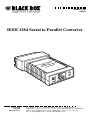
AUGUST 1999
PI049A
IEEE 1284 Serial to Parallel Converter
84 llel
E 12 ara
IEEal to Pverter
i
Ser Con
CUSTOMER
SUPPORT
INFORMATION
Order toll-free in the U.S.: Call 877-877-BBOX (outside U.S. call 724-746-5500)
FREE technical support 24 hours a day, 7 days a week: Call 724-746-5500 or fax 724-746-0746
Mailing address: Black Box Corporation, 1000 Park Drive, Lawrence, PA 15055-1018
Web site: www.blackbox.com • E-mail: [email protected]
IEEE 1284 SERIAL TO PARALLEL CONVERTER
TRADEMARKS USED IN THIS MANUAL
Centronics is a registered trademark of Centronics Corporation.
DEC is a trademark of Digital Equipment Corporation.
Hewlett-Packard and LaserJet are registered trademarks of Hewlett-Packard.
Any other trademarks used in this manual are acknowledged to be the property of
the trademark owners.
1
IEEE 1284 SERIAL TO PARALLEL CONVERTER
FEDERAL COMMUNICATIONS COMMISSION
AND
CANADIAN DEPARTMENT OF COMMUNICATIONS
RADIO FREQUENCY INTERFERENCE STATEMENTS
This equipment generates, uses, and can radiate radio frequency energy and if not
installed and used properly, that is, in strict accordance with the manufacturer’s
instructions, may cause interference to radio communication. It has been tested
and found to comply with the limits for a Class A computing device in accordance
with the specifications in Subpart J of Part 15 of FCC rules, which are designed to
provide reasonable protection against such interference when the equipment is
operated in a commercial environment. Operation of this equipment in a
residential area is likely to cause interference, in which case the user at his own
expense will be required to take whatever measures may be necessary to correct the
interference.
Changes or modifications not expressly approved by the party responsible for
compliance could void the user’s authority to operate the equipment.
This digital apparatus does not exceed the Class A limits for radio noise emission from digital
apparatus set out in the Radio Interference Regulation of Industry Canada.
Le présent appareil numérique n’émet pas de bruits radioélectriques dépassant les limites
applicables aux appareils numériques de la classe A prescrites dans le Règlement sur le
brouillage radioélectrique publié par Industrie Canada.
2
IEEE 1284 SERIAL TO PARALLEL CONVERTER
NORMAS OFICIALES MEXICANAS (NOM)
ELECTRICAL SAFETY STATEMENT
INSTRUCCIONES DE SEGURIDAD
1. Todas las instrucciones de seguridad y operación deberán ser leídas antes de
que el aparato eléctrico sea operado.
2. Las instrucciones de seguridad y operación deberán ser guardadas para
referencia futura.
3. Todas las advertencias en el aparato eléctrico y en sus instrucciones de
operación deben ser respetadas.
4. Todas las instrucciones de operación y uso deben ser seguidas.
5. El aparato eléctrico no deberá ser usado cerca del agua—por ejemplo, cerca
de la tina de baño, lavabo, sótano mojado o cerca de una alberca, etc..
6. El aparato eléctrico debe ser usado únicamente con carritos o pedestales que
sean recomendados por el fabricante.
7. El aparato eléctrico debe ser montado a la pared o al techo sólo como sea
recomendado por el fabricante.
8. Servicio—El usuario no debe intentar dar servicio al equipo eléctrico más allá
a lo descrito en las instrucciones de operación. Todo otro servicio deberá ser
referido a personal de servicio calificado.
9. El aparato eléctrico debe ser situado de tal manera que su posición no
interfiera su uso. La colocación del aparato eléctrico sobre una cama, sofá,
alfombra o superficie similar puede bloquea la ventilación, no se debe colocar
en libreros o gabinetes que impidan el flujo de aire por los orificios de
ventilación.
10. El equipo eléctrico deber ser situado fuera del alcance de fuentes de calor
como radiadores, registros de calor, estufas u otros aparatos (incluyendo
amplificadores) que producen calor.
11. El aparato eléctrico deberá ser connectado a una fuente de poder sólo del
tipo descrito en el instructivo de operación, o como se indique en el aparato.
3
IEEE 1284 SERIAL TO PARALLEL CONVERTER
12. Precaución debe ser tomada de tal manera que la tierra fisica y la polarización
del equipo no sea eliminada.
13. Los cables de la fuente de poder deben ser guiados de tal manera que no
sean pisados ni pellizcados por objetos colocados sobre o contra ellos,
poniendo particular atención a los contactos y receptáculos donde salen del
aparato.
14. El equipo eléctrico debe ser limpiado únicamente de acuerdo a las
recomendaciones del fabricante.
15. En caso de existir, una antena externa deberá ser localizada lejos de las lineas
de energia.
16. El cable de corriente deberá ser desconectado del cuando el equipo no sea
usado por un largo periodo de tiempo.
17. Cuidado debe ser tomado de tal manera que objectos liquidos no sean
derramados sobre la cubierta u orificios de ventilación.
18. Servicio por personal calificado deberá ser provisto cuando:
A: El cable de poder o el contacto ha sido dañado; u
B: Objectos han caído o líquido ha sido derramado dentro del aparato; o
C: El aparato ha sido expuesto a la lluvia; o
D: El aparato parece no operar normalmente o muestra un cambio en su
desempeño; o
E: El aparato ha sido tirado o su cubierta ha sido dañada.
4
IEEE 1284 SERIAL TO PARALLEL CONVERTER
CE Notice
The CE symbol on your IEEE 1284 Serial to Parallel Converter indicates that it is in
compliance with the Electromagnetic Compatibility (EMC) directive and the Low
Voltage Directive (LVD) of the Union European (EU).
5
IEEE 1284 SERIAL TO PARALLEL CONVERTER
Contents
Chapter
Page
1.
Specifications ......................................................................................................7
2.
Introduction ........................................................................................................8
3.
2.1
Description ..............................................................................................8
2.2
Features ....................................................................................................8
Configuration ......................................................................................................9
3.1
Configuration Switches ..........................................................................9
3.2
Detailed Switch Settings ..........................................................................9
4.
Installation ........................................................................................................11
5.
Operation ..........................................................................................................12
Appendix: Interface Connections ..........................................................................13
6
IEEE 1284 SERIAL TO PARALLEL CONVERTER
1. Specifications
Transmission Format—
Serial side: Asynchronous, full duplex; Parallel side:
IEEE 1284 BiTronics, supporting Compatibility and
Nibble Modes (switchable)
Data Rates—
9.6, 19.2, 38.4, and 115.2 kbps
Range—
Meets capacitive and resistive load requirements of
RS-232 and RS-423
ESD Protection—
4KV
Connectors—
Parallel connection: Male 36-pin Centronics® or MiniCentronics 36; Serial connection: DEC™ MMJ jack,
RJ-45 jack, or DB25 (male or female)
Temperature Range—
32 to 140°F (0 to 60°C)
Humidity Tolerance—
5 to 95% noncondensing
Altitude Tolerance—
Up to 10,100 feet (3078.5 m)
Power Supply—
Power derived from RS-232/423 and IEEE-1284
interfaces
NOTE
IEEE 1284 B interface must support the optional 5V on pin 18, and IEEE
1284 C must support interface pin 36 (peripheral logic high). Otherwise,
power must be supplied using the optional AC wallmount power supply
(PS095).
Size—
3"H x 2"W x 0.75"D (7.6 x 5.1 x 1.9 cm)
Weight —
0.5 lb. (0.2 kg)
7
IEEE 1284 SERIAL TO PARALLEL CONVERTER
2. Introduction
2.1 Description
The IEEE 1284 Serial to Parallel Converter lets you connect RS-232/423 serial
hardware to a printer or other device equipped with a BiTronics parallel interface.
Able to work in either Level 1 Compatible or Nibble modes (according to the IEEE
1284 standard), the Converter supports the high speeds necessary for graphicsintensive laser-printer applications.
On the serial side, the Converter translates Nibble operations into standard
Hewlett-Packard® LaserJet® IV serial printer escape sequences. This allows
operation with standard printer drivers. On the parallel side, the Model 2030
translates all commands received from the serial device into BiTronics Nibble
operations or Compatible operations (depending upon the mode selected).
The IEEE 1284 Serial to Parallel Converter works with all BiTronics Level 1
compatible hardware, including Level 2 hardware with Level 1 backward
compatibility. Power may be supplied by both interfaces, or by an optional plug-in
AC adapter (PS095).
2.2 Features
• Supports data rates up to 115.2 kbps.
• Supports two IEEE 1284 BiTronics modes: Compatible and Nibble (switchable).
• 4KV ESD protection on serial interface.
• Power derived from both interfaces, or from external AC power supply.
• LEDs for Power and Data mode (distinctive blinking).
• Male 36-pin Centronics or Mini-Centronics 36 for parallel connection.
• DEC MMJ jack, RJ-45 jack, or DB25 (male or female) for serial connection.
• Miniature size.
8
IEEE 1284 SERIAL TO PARALLEL CONVERTER
3. Configuration
3.1 Configuration Switches
The Converter uses a set of eight external DIP switches that allow configuration to
a wide range of applications. Because all eight switches are in one externally
accessible DIP-switch package, there is no need to open the case for configuration.
The configuration switches allow you to select data rates, parity, word length, and
flow-control selection.
To set the switches:
1. Open the Converter’s case by inserting a small flat-blade screwdriver in the
slot on either side of the case and twisting gently.
2. Having exposed the PC board, you will see the miniature DIP-switch packet on
the side of the board nearest the Centronics® connector.
3. Use a small screwdriver and gently push each switch to its proper setting. The
ON position is printed on the switch packet.
4. Fit the case halves and end plate together and push to snap closed.
3.2 Detailed Switch Settings
The DIP switches on the Converter’s PC board are labeled 1 through 8. Only
switches 1 through 4 are used. Switches 5 through 8 have no function.
SWITCH 1: HARDWARE/SOFTWARE CONTROL
The setting for Switch 1 determines whether the Converter will use hardware or
software (X-on/X-off) flow control.
Flow Control
Hardware
Software
SW1
OFF (factory default)
ON
9
IEEE 1284 SERIAL TO PARALLEL CONVERTER
SWITCH 2: REVERSE FLOW CONTROL
The setting for Switch 2 determines whether the serial device receives reverse flow
control information from the printer (see IEEE 1284 specification for details on
reverse flow control).
Reverse Flow Control
Hardware (Nibble)
None (Compatible)
SW2
OFF (factory default)
ON
SWITCHES 3 AND 4: DATA RATE
Switches 3 and 4 set the serial data rate for the Converter.
Data Rate
9600 bps
19,200 bps
38,400 bps
115,200 bps
SW3
OFF (factory default)
OFF
ON
ON
SWITCHES 5 THROUGH 8: FUTURE USE
10
SW4
OFF (factory default)
ON
OFF
ON
IEEE 1284 SERIAL TO PARALLEL CONVERTER
4. Installation
Once you have configured the Converter, follow these installation instructions.
1. Plug the Converter directly into the 36-pin Centronics® interface. Where
necessary, a short (no more than 6 ft. or 1.8 m) parallel printer cable may be
used.
2. The RS-232 interface is wired as a DCE (see below) according to the EIA-561
standard. Connect the Converter to your serial RS-232 DTE device using a
straight-through modular cable.
RJ-45 (DCE)
1
2
3
4
5
6
7
8
Signal
----------------------------DSR
----------------------------CD
----------------------------DTR
----------------------------SG
----------------------------RD
----------------------------TD
----------------------------CTS
----------------------------RTS
3. The Converter derives power from the RS-232/423 and IEEE 1284 interfaces.
IMPORTANT
For the Converter to operate as an interface-powered device, the IEEE
1284 B interface must support the optional 5V on pin 18, and IEEE 1284
C must support interface pin 36 (peripheral logic high). If the IEEE 1284
interface does not meet these requirements, you must supply power to
the Converter using the optional wallmount AC power supply (PS095).
11
IEEE 1284 SERIAL TO PARALLEL CONVERTER
5. Operation
Once the Converter is properly configured and installed, it should operate
transparently—as if it were a standard cable connection. There is no ON/OFF
switch.
LED Status Monitors
The Converter features two easy-to-read status LEDs. The green LED glows when
optional AC power (from the optional PS095 power supply) is applied to the unit.
The red LED indicator blinks to show data activity. Since there is only one
indicator, it uses different LED codes to demonstrate various messages. The
following chart describes these codes.
LED Codes
● ● — ● ——— ● ● — ● ———
Computer is sending data.
● ——— ● ——— ● ———
Serial device is connected; computer is not
sending data.
● ● ——— ● ● ———
Both serial and parallel devices are connected;
computer not sending data.
● — ● ——— ● — ● ————
Printer not ready, data held in buffer.
● ● ● ● ———● ● ● ●
Computer ignoring flow control, data lost.
Key
●
—
———
12
Blink
Short pause
Long pause
IEEE 1284 SERIAL TO PARALLEL CONVERTER
Appendix: Interface Connections
36-Pin Centronics Parallel Port Connections
Pin
Description
1
2
3
4
5
6
7
8
9
10
11
12
13
16
17
18
Strobe
Data bit 0
Data bit 1
Data bit 2
Data bit 3
Data bit 4
Data bit 5
Data bit 6
Data bit 7
Acknowledge
Busy
Paper end
Select
Logic Ground
Chassis Ground
+5 volts
(19, 20, 21, 22, 23, 24,
25, 26, 27, 28, 29, 30)
Init
Error
nSelectIn
31
32
36
Direction
Output
}
I/O
Input (active low)
Input (active high)
}
Ground
Note: All other pins are unconnected.
13
© Copyright 1999. Black Box Corporation. All rights reserved.
1000 Park Drive
•
Lawrence, PA 15055-1018
•
724-746-5500
•
Fax 724-746-0746