1
CÓPIA NÃO CONTROLADA
®
®
G031/G032/G049/G054
SERVICE MANUAL
000832MIU
RICOH GROUP COMPANIES
CÓPIA NÃO CONTROLADA
CÓPIA NÃO CONTROLADA
CÓPIA NÃO CONTROLADA
CÓPIA NÃO CONTROLADA
®
®
G031/G032/G049/G054
SERVICE MANUAL
RICOH GROUP COMPANIES
CÓPIA NÃO CONTROLADA
CÓPIA NÃO CONTROLADA
CÓPIA NÃO CONTROLADA
CÓPIA NÃO CONTROLADA
G031/G032/G049/G054
SERVICE MANUAL
000832MIU
CÓPIA NÃO CONTROLADA
CÓPIA NÃO CONTROLADA
CÓPIA NÃO CONTROLADA
CÓPIA NÃO CONTROLADA
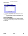
It is the reader's responsibility when discussing the information contained within this
document to maintain a level of confidentiality that is in the best interest of Ricoh
Corporation and its member companies.
NO PART OF THIS DOCUMENT MAY BE REPRODUCED IN ANY
FASHION AND DISTRIBUTED WITHOUT THE PRIOR
PERMISSION OF RICOH CORPORATION.
All product names, domain names or product illustrations, including desktop images,
used in this document are trademarks, registered trademarks or the property of their
respective companies.
They are used throughout this book in an informational or editorial fashion only and for
the benefit of such companies. No such use, or the use of any trade name, or web
site is intended to convey endorsement or other affiliation with Ricoh products.
2000 RICOH Corporation. All rights reserved.
CÓPIA NÃO CONTROLADA
CÓPIA NÃO CONTROLADA
CÓPIA NÃO CONTROLADA
CÓPIA NÃO CONTROLADA
WARNING
The Service Manual contains information
regarding
service
techniques,
procedures,
processes and spare parts of office equipment
distributed by Ricoh Corporation. Users of this
manual should be either service trained or
certified by successfully completing a Ricoh
Technical Training Program.
Untrained and uncertified users utilizing
information contained in this service manual to
repair or modify Ricoh equipment risk personal
injury, damage to property. or loss of warranty
protection.
Ricoh Corporation
CÓPIA NÃO CONTROLADA
CÓPIA NÃO CONTROLADA
CÓPIA NÃO CONTROLADA
CÓPIA NÃO CONTROLADA
Rev. 7/2000
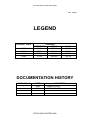
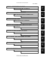
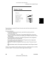
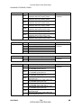
LEGEND
PRODUCT CODE
G031
G032
G049
G054
COMPANY
GESTETNER
RICOH
P7020
AP2000
P7014
AP1400
P7021
AP2100
P7016
AP1600
SAVIN
SLP20
SLP14
SLP21
SLP16
DOCUMENTATION HISTORY
REV. NO.
*
DATE
5/99
4/2000
COMMENTS
Original Printing
G049/G054 Addition
CÓPIA NÃO CONTROLADA
CÓPIA NÃO CONTROLADA
CÓPIA NÃO CONTROLADA
CÓPIA NÃO CONTROLADA
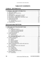
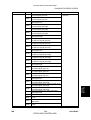
TABLE OF CONTENTS
OVERALL INFORMATION
1. OVERALL MACHINE INFORMATION ........................................ 1-1
1.1
1.2
1.3
1.4
1.5
1.6
1.7
1.8
SPECIFICATIONS.....................................................................................1-1
MACHINE CONFIGURATION ...................................................................1-5
PAPER PATH............................................................................................1-6
MECHANICAL COMPONENT LAYOUT....................................................1-7
ELECTRICAL COMPONENT LAYOUT .....................................................1-8
ELECTRICAL COMPONENT DESCRIPTIONS ......................................1-10
PRINTING PROCESS .............................................................................1-12
BOARD STRUCTURE.............................................................................1-14
1.8.1 OVERVIEW ....................................................................................1-14
1.8.2 MAJOR COMPONENTS ................................................................1-15
1.9 COMPARISON ........................................................................................1-16
DETAILED DESCRIPTIONS
2. DETAILED SECTION DESCRIPTIONS ...................................... 2-1
2.1 PRINTING .................................................................................................2-1
2.1.1 IMAGE DATA PATH .........................................................................2-1
2.1.2 PRINTER CONTROL BOARD..........................................................2-2
2.1.3 IMAGE DATA PROCESSIING..........................................................2-3
2.1.4 HOST INTERFACE ..........................................................................2-4
2.2 LASER EXPOSURE ..................................................................................2-5
2.2.1 OVERVIEW ......................................................................................2-5
2.2.2 OPTICAL PATH................................................................................2-6
2.2.3 AUTO POWER CONTROL (APC) ....................................................2-8
2.2.4 LD SAFETY SWITCH .......................................................................2-9
2.3 TONER CARTRIDGE ..............................................................................2-10
2.3.1 OVERVIEW ....................................................................................2-10
2.3.2 DRIVE.............................................................................................2-11
2.3.3 DRUM CHARGE.............................................................................2-12
2.3.4 DEVELOPMENT.............................................................................2-13
2.3.5 DRUM CLEANING..........................................................................2-15
2.4 IMAGE TRANSFER AND PAPER SEPARATION ...................................2-16
2.4.1 OVERVIEW ....................................................................................2-16
2.4.2 TRANSFER ROLLER CLEANING..................................................2-17
2.5 PAPER FEED..........................................................................................2-18
2.5.1 OVERVIEW ....................................................................................2-18
2.5.2 PAPER TRAY .................................................................................2-20
2.5.3 BY-PASS TRAY..............................................................................2-25
2.5.4 PAPER REGISTRATION................................................................2-27
2.6 IMAGE FUSING ......................................................................................2-29
2.6.1 OVERVIEW ....................................................................................2-29
SM
i
CÓPIA NÃO CONTROLADA
G031/G032/G049/G054
CÓPIA NÃO CONTROLADA
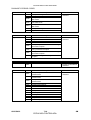
2.6.2 FUSING ..........................................................................................2-30
2.6.3 FUSING UNIT DRIVE.....................................................................2-30
2.6.4 PRESSURE ROLLER/PAPER EXIT...............................................2-31
2.6.5 FUSING UNIT DRIVE RELEASE ...................................................2-31
2.6.6 NEW FUSING UNIT DETECTION (STINGER - P3 ONLY) ............2-32
2.6.7 FUSING TEMPERATURE CONTROL............................................2-33
2.6.8 OVERHEAT PROTECTION............................................................2-35
2.6.9 ENERGY SAVER MODE................................................................2-36
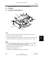
2.7 COVER OPEN DETECTION ...................................................................2-37
2.7.1 FRONT COVER LOCK...................................................................2-37
2.7.2 FRONT COVER SAFETY SWITCH................................................2-37
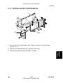
2.7.3 REMOVING THE FUSING UNIT ....................................................2-38
2.8 ENGINE CONTROL BOARD...................................................................2-39
2.8.1 PCB LAYOUT .................................................................................2-39
2.8.2 DEVICES ........................................................................................2-40
2.8.3 STRUCTURE..................................................................................2-41
2.8.4 CONNECTION TO THE ECB .........................................................2-42
2.9 SIGNAL TABLE .......................................................................................2-44
2.10 PRINTER CONTROL BOARD...............................................................2-47
2.10.1 PCB LAYOUT ...............................................................................2-47
2.10.2 DEVICES ......................................................................................2-48
INSTALLATION
3. INSTALLATION .......................................................................... 3-1
3.1 INSTALLATION REQUIREMENTS ...........................................................3-1
3.1.1 ENVIRONMENT ...............................................................................3-1
3.1.2 POWER REQUIREMENTS ..............................................................3-1
3.2 PRINTER INSTALLATION ........................................................................3-2
3.3 PAPER FEED UNIT INSTALLATION ........................................................3-2
3.4 ENVELOPE FEEDER INSTALLATION .....................................................3-2
3.5 HARD DISK INSTALLATION.....................................................................3-2
3.6 MEMORY UNIT INSTALLATION...............................................................3-2
3.7 NETWORK INTERFACE BOARD INSTALLATION...................................3-2
3.8 CHECKING THE CONNECTIONS ............................................................3-3
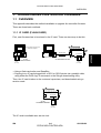
3.8.1 CONNECTION BETWEEN MAIN PRINTER CONTROL BOARD
(AND RELATED OPTIONS: HDD, RAM SIMM, NIC) AND
OPTIONAL HDD & PERIPHERALS .................................................3-3
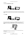
3.8.2 CONNECTION BETWEEN PRINTER CONTROL BOARD AND
NETWORK INTERFACE BOARD ....................................................3-6
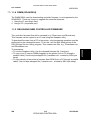
3.8.3 PRINTING THE NETWORK INTERFACE BOARD
CONFIGURATION SHEET...............................................................3-6
SERVICE TABLES AND PROCEDURES
4. SERVICE PROCEDURES AND TABLES ................................... 4-1
4.1 OVERVIEW ...............................................................................................4-1
4.2 SERVICE PROGRAM MODE....................................................................4-2
G031/G032/G049/G054
ii
CÓPIA NÃO CONTROLADA
SM
CÓPIA NÃO CONTROLADA
Rev. 01/2003
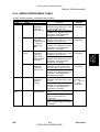
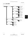
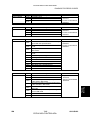
4.2.1 ENABLING AND DISABLING SERVICE PROGRAM MODE ...........4-2
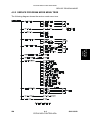
4.2.2 SERVICE PROGRAM MODE MENU TREE.....................................4-3
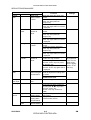
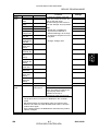
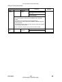
4.2.3 SERVICE MODE MENU TABLE ......................................................4-5
4.2.4 PRINT LOG ......................................................................................4-9
4.2.5 PRINTER ID ...................................................................................4-13
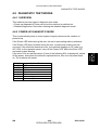
4.3 IC CARD BOOT SERVICE MODE ..........................................................4-15
4.3.1 OVERVIEW ....................................................................................4-15
4.3.2 ENABLING AND DISABLING IC CARD BOOT SERVICE
MODE.............................................................................................4-15
4.3.3 IC CARD BOOT SERVICE MODE TREE .......................................4-16
4.3.4 SERVICE MENU TABLE ................................................................4-17
4.4 EEPROM AND NVRAM RESET PROCEDURES ...................................4-18
4.5 DOWNLOADING NEW CONTROLLER SOFTWARE .............................4-19
4.5.1 OVERVIEW ....................................................................................4-19
4.5.2 DOWNLOADING NEW FIRMWARE FROM AN IC CARD .............4-20
4.6 USER MENU ...........................................................................................4-23
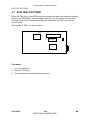
4.7 ECB TEST PATTERN .............................................................................4-24
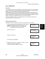
4.8 DIAGNOSTIC TEST MODES ..................................................................4-25
4.8.1 OVERVIEW ....................................................................................4-25
4.8.2 POWER-UP DIAGNOSTIC MODE .................................................4-25
4.8.3 DETAILED DIAGNOSTIC MODE ...................................................4-26
4.8.4 DIAGNOSTIC TEST DETAILS .......................................................4-27
4.9 FIRMWARE HISTORY ............................................................................4-29
4.9.1 CONTROLLER FIRMWARE HISTORY (G031)..............................4-29
4.9.2 CONTROLLER FIRMWARE HISTORY (G032)..............................4-30
PREVENTIVE MAINTENANCE
5. PREVENTIVE MAINTENANCE.................................................... 5-1
5.1 PREVENTIVE MAINTENANCE SCHEDULE ............................................5-1
REPLACEMENT AND ADJUSTMENT
6. REPLACEMENT AND ADJUSTMENT ........................................ 6-1
6.1 COVERS ...................................................................................................6-1
6.1.1 EXTERIOR COVER REMOVAL .......................................................6-1
6.1.2 FRONT COVER REMOVAL .............................................................6-2
6.1.3 CONTROL BOARD COVER REMOVAL ..........................................6-3
6.2 FUSING UNIT............................................................................................6-4
6.2.1 FUSING UNIT REPLACEMENT .......................................................6-4
6.2.2 HOT ROLLER AND FUSING LAMP REPLACEMENT .....................6-5
6.2.3 PRESSURE ROLLER REPLACEMENT...........................................6-7
6.2.4 FUSING THERMOFUSE REPLACEMENT ......................................6-8
6.2.5 FUSING DRAWER CONNECTOR REPLACEMENT .......................6-9
6.3 TRANSFER ROLLER ..............................................................................6-10
6.3.1 TRANSFER ROLLER REPLACEMENT .........................................6-10
6.4 PAPER FEED..........................................................................................6-11
6.4.1 BY-PASS TRAY REMOVAL ...........................................................6-11
SM
iii
CÓPIA NÃO CONTROLADA
G031/G032/G049/G054
Rev. 03/2000
CÓPIA NÃO CONTROLADA
6.4.2 BY-PASS FEED ROLLER REPLACEMENT ..................................6-12
6.4.3 PAPER FEED ROLLER REPLACEMENT......................................6-15
6.4.4 RELAY ROLLER REPLACEMENT (STINGER - P4 ONLY) ...........6-17
6.4.5 FRICTION PAD REPLACEMENT...................................................6-18
6.4.6 TRAY PAPER FEED CLUTCH REPLACEMENT ...........................6-19
6.5 LASER UNIT ...........................................................................................6-20
6.5.1 CAUTION DECAL LOCATIONS .....................................................6-20
6.5.2 LASER UNIT/SHIELD GLASS REPLACEMENT ............................6-21
6.5.3 LD UNIT/LASER SYNCHRONIZATION DETECTOR
REPLACEMENT.............................................................................6-22
6.5.4 POLYGONAL MIRROR MOTOR REPLACEMENT ........................6-23
6.5.5 LD UNIT/POLYGONAL MIRROR MOTOR REPLACEMENT .........6-24
6.6 OTHERS..................................................................................................6-25
6.6.1 TONER NEAR-END SENSOR REPLACEMENT............................6-25
6.6.2 MAIN MOTOR/GEAR BOX REMOVAL ..........................................6-26
6.6.3 ENGINE CONTROL BOARD REPLACEMENT ..............................6-27
6.6.4 PRINTER CONTROL BOARD REPLACEMENT ............................6-28
6.6.5 HIGH VOLTAGE SUPPLY BOARD ................................................6-29
6.6.6 POWER SUPPLY UNIT REPLACEMENT ......................................6-30
6.7 PRINT REGISTRATION ADJUSTMENT .................................................6-31
TROUBLESHOOTING
7. TROUBLESHOOTING ................................................................ 7-1
7.1 OPERATOR ERRORS ..............................................................................7-1
7.2 PRINTER ENGINE SC CODES ................................................................7-6
7.3 DIAGNOSTIC ERROR CODES.................................................................7-9
7.3.1 DIAGNOSTIC ERROR CODE TABLE..............................................7-9
7.4 ELECTRICAL COMPONENT DEFECTS.................................................7-17
7.4.1 SENSORS ......................................................................................7-17
7.4.2 SWITCHES.....................................................................................7-17
7.4.3 FUSES............................................................................................7-17
ENVELOPE FEEDER G913
1. OVERALL INFORMATION.......................................................... 8-1
1.1 SPECIFICATIONS.....................................................................................8-1
1.2 MECHANICAL COMPONENT LAYOUT....................................................8-1
2. DETAILED SECTION DESCRIPTIONS ...................................... 8-2
2.1 PAPER LIFT ..............................................................................................8-2
3. INSTALLATION .......................................................................... 8-3
4. REPLACEMENT AND ADJUSTMENT........................................ 8-4
4.1 FRICTION PAD REPLACEMENT .............................................................8-4
G031/G032/G049/G054
iv
CÓPIA NÃO CONTROLADA
SM
CÓPIA NÃO CONTROLADA
PAPER FEED UNIT G914/G915
1. OVERALL MACHINE INFORMATION ........................................ 9-1
1.1 SPECIFICATIONS.....................................................................................9-1
1.1.1 STINGER - P3 ..................................................................................9-1
1.1.2 STINGER - P4 ..................................................................................9-1
1.2 MECHANICAL COMPONENT LAYOUT....................................................9-2
1.3 ELECTRICAL COMPONENT LAYOUT .....................................................9-3
1.4 ELECTRICAL COMPONENT DESCRIPTION...........................................9-4
2. DETAILED SECTION DESCRIPTIONS ...................................... 9-5
2.1
2.2
2.3
2.4
2.5
PAPER SIZE DETECTION........................................................................9-5
PAPER LIFT ..............................................................................................9-5
PAPER END DETECTION ........................................................................9-5
PAPER NEAR END DETECTION .............................................................9-5
PAPER FEED............................................................................................9-6
3. INSTALLATION .......................................................................... 9-8
4. REPLACEMENT AND ADJUSTMENT........................................ 9-9
4.1 PAPER FEED UNIT (OPTION FOR STINGER - P3) ................................9-9
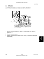
4.1.1 PAPER FEED ASSEMBLY REMOVAL ............................................9-9
4.1.2 DRIVE ROLLER REPLACEMENT..................................................9-10
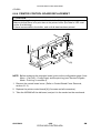
4.1.3 PAPER FEED MOTOR REPLACEMENT.......................................9-11
4.1.4 PAPER FEED CLUTCH REMOVAL ...............................................9-12
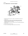
4.1.5 PAPER FEED UNIT BOARD/PAPER SIZE SWITCH
REPLACEMENT.............................................................................9-13
4.2 PAPER FEED UNIT (OPTION FOR STINGER - P4) ..............................9-14
4.2.1 PAPER FEED ROLLER/PAPER FEED CLUTCH
REPLACEMENT.............................................................................9-14
4.2.2 PAPER DRIVE ROLLER REPLACEMENT ....................................9-15
4.2.3 DRIVE ROLLER IDLER/FRICTION PAD REPLACEMENT ............9-16
4.2.4 PAPER FEED MOTOR/PAPER FEED UNIT BOARD
REPLACEMENT.............................................................................9-17
NETWORK INTERFACE BOARD G919 (TYPE2000)
1. OVERALL MACHINE INFORMATION ...................................... 10-1
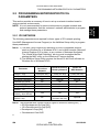
1.1 SPECIFICATIONS...................................................................................10-1
2. INSTALLATION PROCEDURE................................................. 10-2
2.1 HARDWARE INSTALLATION .................................................................10-2
2.1.1 SERIAL NUMBER AND MAC ADDRESS.......................................10-2
2.1.2 STATUS SHEET.............................................................................10-2
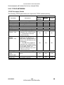
2.2 PROGRAMMING NETWORK/PROTOCOL PARAMETERS...................10-3
2.2.1 IPX NETWORK...............................................................................10-3
2.2.2 TCP/IP NETWORK.........................................................................10-4
2.2.3 ETHERTALK (APPLETALK) NETWORK .......................................10-5
SM
v
CÓPIA NÃO CONTROLADA
G031/G032/G049/G054
CÓPIA NÃO CONTROLADA
Rev. 01/2003
2.3 SETUP FOR VARIOUS NETWORK TYPES ...........................................10-6
2.3.1 PEER-TO-PEER NETWORK..........................................................10-6
2.3.2 NOVELL NETWARE NETWORK ...................................................10-7
2.3.3 TCP/IP NETWORK.........................................................................10-7
3. SERVICE TABLES AND PROCEDURES.................................. 10-8
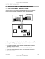
3.1 FACTORY RESET (NVRAM CLEAR) .....................................................10-8
3.2 FLASH ROM UPDATE ............................................................................10-9
3.2.1 INTRODUCTION ............................................................................10-9
3.2.2 FLASHUP UTILITY (FOR NOVELL IPX NETWORKS) ................10-10
3.2.3 FTPDL UTILITY (FOR TCP/IP NETWORKS) ...............................10-13
4. TROUBLESHOOTING ............................................................. 10-16
4.1 LED INDICATIONS ................................................................................10-16
4.2 NIB FIRMWARE MODIFICATION HISTORY..………………...…………10-17
G049/G054 SERVICE MANUAL
OVERALL INFORMATION
1. OVERALL MACHINE INFORMATION....................................... 11-1
1.1 SPECIFICATIONS...................................................................................11-1
1.2 MACHINE CONFIGURATION .................................................................11-2
DETAILED DESCRIPTIONS
2. DETAILED SECTION DESCRIPTIONS ..................................... 11-3
2.5 PAPER FEED………………………………………………………………….11-3
2.5.1 OVERVIEW GO54..........................................................................11-3
2.10 PRINTER CONTROL BOARD........................................ ……………….11-3
2.10.2 DEVICES………………………………………………………………11-5
3. G049/G054 FIRMWARE HISTORY............................................ 11-6
3.1
3.2
3.3
3.4
G049 ENGINE FIRMWARE MODIFICATION HISTORY ..........................11-6
G054 ENGINE FIRMWARE MODIFICATION HISTORY ..........................11-6
G049 CONTROLLER FIRMWARE MODIFICATION HISTORY ...............11-7
G054 CONTROLLER FIRMWARE MODIFICATION HISTORY ...............11-8
G031/G032/G049/G054
vi
CÓPIA NÃO CONTROLADA
SM
CÓPIA NÃO CONTROLADA
APPENDIX
1. DOWNLOADING CONTROLLER FIRMWARE ........... APPENDIX-1
1.1 OVERVIEW ...............................................................................APPENDIX-1
1.1.1 IC CARD (FLASH CARD) .................................................APPENDIX-1
1.1.2 PC, VIA PARALLEL PORT ...............................................APPENDIX-2
1.1.3 DIMM ................................................................................APPENDIX-2
1.1.4 RELEASING NEW CONTROLLER FIRMWARE ..............APPENDIX-3
1.2 SERVICE TOOLS......................................................................APPENDIX-4
1.2.1 OPERATION PANEL........................................................APPENDIX-4
1.2.2 SERVICE TOOL MENUS .................................................APPENDIX-5
1.2.3 STINGER SERVICE UTILITY (SSU) ................................APPENDIX-7
1.3 USING AN IC CARD .................................................................APPENDIX-8
1.3.1 PREPARING THE IC CARD.............................................APPENDIX-8
1.3.2 DOWNLOADING FROM THE IC CARD TO
THE PRINTER................................................................APPENDIX-13
1.4 USING A DIMM .......................................................................APPENDIX-14
1.4.1 PREPARING THE DIMM................................................APPENDIX-14
1.4.2 DOWNLOADING FROM THE DIMM TO
THE PRINTER................................................................APPENDIX-19
1.5 COPYING FROM A PC DIRECTLY ........................................APPENDIX-20
1.5.1 PREPARATION ..............................................................APPENDIX-20
1.5.2 DOWNLOADING TO THE FLASH MEMORY.................APPENDIX-22
1.6 SSU TROUBLESHOOTING ....................................................APPENDIX-26
SM
vii
CÓPIA NÃO CONTROLADA
G031/G032/G049/G054
CÓPIA NÃO CONTROLADA
CÓPIA NÃO CONTROLADA
CÓPIA NÃO CONTROLADA
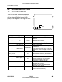
IMPORTANT SAFETY NOTICES
PREVENTION OF PHYSICAL INJURY
1. Before disassembling or assembling parts of the printer and peripherals,
make sure that the printer power cord is unplugged.
2. The wall outlet should be near the printer and easily accessible.
3. If any adjustment or operation check has to be made with exterior covers off
or open while the main switch is turned on, keep hands away from electrified
or mechanically driven components.
4. If a print job has started (the Data In LED has started blinking) before the
printer completes the warm-up or initializing period, keep hands away from
the mechanical and electrical components because the printer starts making
prints as soon as the warm-up period is completed.
5. The inside and the metal parts of the fusing unit become extremely hot while
the printer is operating. Avoid touching those components with your bare
hands.
HEALTH SAFETY CONDITIONS
Toner is non-toxic, but if you get it in your eyes by accident, it may cause
temporary eye discomfort. Try to remove with eye drops or flush with water as
first aid. If unsuccessful, get medical attention.
SAFETY AND ECOLOGICAL NOTES FOR DISPOSAL
1. Do not incinerate the toner cassettes. Toner dust may ignite suddenly when
exposed to an open flame.
2. Dispose of toner cassettes in accordance with local regulations. (This is a
non-toxic unit.)
3. Dispose of replaced parts in accordance with local regulations.
SM
a
CÓPIA NÃO CONTROLADA
G031/G032
CÓPIA NÃO CONTROLADA
LASER SAFETY
The Center for Devices and Radiological Health (CDRH) prohibits the repair of
laser-based optical units in the field. The optical housing unit can only be repaired
in a factory or at a location with the requisite equipment. The laser subsystem is
replaceable in the field by a qualified Customer Engineer. The laser chassis is not
repairable in the field. Customer engineers are therefore directed to return all
chassis and laser subsystems to the factory or service depot when replacement of
the optical subsystem is required.
WARNING
Use of controls, or adjustment, or performance of procedures other than
those specified in this manual may result in hazardous radiation exposure.
WARNING FOR LASER UNIT
WARNING: Turn off the main switch before attempting any of the
procedures in the Laser Unit section. Laser beams can
seriously damage your eyes.
CAUTION MARKING:
G031/G032
b
CÓPIA NÃO CONTROLADA
SM
CÓPIA NÃO CONTROLADA
INSTALLATION G031/G032
G049/G054 SERVICE MANUAL
SERVICE PROCEDURES AND TABLES G031/G032
APPENDIX
PREVENTIVE MAINTENANCE G031/G032
TAB
POSITION 2
TROUBLESHOOTING G031/G032
TAB
POSITION 7
ENVELOPE FEEDER G913
TAB
POSITION 8
REPLACEMENT AND ADJUSTMENT G031/G032
TAB
POSITION 3
NETWORK INTERFACE BOARD G919
TAB
POSITION 4
DETAILED DESCRIPTIONS G031/G032
TAB
POSITION 5
PAPER FEED UNIT G914/G915
TAB
POSITION 6
OVERALL INFORMATION G031/G032
TAB
POSITION 1
Rev. 04/2000
CÓPIA NÃO CONTROLADA
CÓPIA NÃO CONTROLADA
CÓPIA NÃO CONTROLADA
CÓPIA NÃO CONTROLADA
OVERALL INFORMATION
CÓPIA NÃO CONTROLADA
CÓPIA NÃO CONTROLADA
CÓPIA NÃO CONTROLADA
CÓPIA NÃO CONTROLADA
SPECIFICATIONS
Overall
Information
1. OVERALL MACHINE INFORMATION
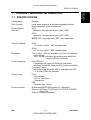
1.1 SPECIFICATIONS
Configuration:
Desktop
Print Process:
Laser beam scanning & electrophotographic printing
Monocomponent toner development
Printing Speed
(600 dpi):
G031:
Maximum 20 pages per minute (A4/LT LEF)
G032:
Maximum 14 pages per minute (A4/LT SEF)
NOTE: LEF, long edge feed. SEF, short edge feed
First Print Speed:
G031:
5.5 s or less (A4/LT - LEF, standard tray)
G032:
6.5 s or less (A4/LT - SEF, standard tray)
Resolution:
True 1,200 x 1,200 dpi (available for PCL6 or PostScript)
600 x 600 dpi
300 x 300 dpi (simulated by doubling pixel width and
height at 600 dpi resolution)
Printer Language
PCL6/PCL5e
Compatible with Laser Jet 5N driver and printer.
Windows 3.1x/95/98, Windows NT4.0 drivers available.
PostScript Level II
Windows 95/98, Windows NT4.0, and Macintosh (OS
7.5 or later) PPDs are available.
Printer Fonts:
PCL6
35 Intellifonts
10 True Type fonts
1 Bitmap font
PS2
35 Adobe type 1 fonts
Printer Interface:
Bi-directional IEEE1284 parallel x 1 (Standard)
Ethernet (100 Base-TX/10 Base-T for TCP/IP, IPX/SPX,
EtherTalk)
RS232C interface (Optional)
SM
1-1
CÓPIA NÃO CONTROLADA
G031/G032
CÓPIA NÃO CONTROLADA
Rev. 04/2000
SPECIFICATIONS
Printing Paper Size:
⇒Printing Paper Weight:
Power Source:
G031:
Maximum A3/11" x 17"
Minimum A5 LEF - Standard Tray
B6 SEF - By-pass Tray
A5 LEF - Optional PFU
Custom paper size (PCL 6/PS): By-pass Tray
11.69" x 17" ~ 3.88" x 5.83"
(297 x 431.8 ~ 98.4 x 148 mm)
Envelope: By-pass & Envelope Feeder
Com#10, C6, DL, Monarch
G032:
Maximum A4/LG (only A4/LT for Standard Tray)
Minimum A4/LT – Standard Tray
B6 SEF - By-pass Tray
A5 LEF - Optional PFU
Custom paper size (PCL 6/PS): By-pass Tray
8.5" x 14" ~ 3.88" x 5.83"
(216 x 355.6 ~ 98.4 x 148 mm)
Envelope: By-pass & Envelope Feeder
Com#10, C6, DL, Monarch
Paper tray: 60 ~ 90 g/m2, 16 ~ 24 lb
By-pass:
60 ~ 162 g/m2, 16 ~ 43 lb
G031:
120 V, 60 Hz: More than 8.0 A (for North America)
220 V ~ 240 V, 50/60 Hz: More than 8.0 A (for Europe)
G032:
120 V, 60 Hz: More than 6.0 A (for North America)
220 V ~ 240 V, 50/60 Hz: More than 5.0 A (for Europe)
Power Consumption:
Maximum
Printing
Energy Saver
G031
G032
795 W or less
480 W or less
30 W or less
600 W or less
380 W or less
30 W or less
Noise Emission (All Options Installed):
Sound Power Level
Printing
Stand-by
G031
G032
64 dB or less
48 dB or less
59 dB or less
48 dB or less
NOTE: The above measurements were made in accordance with ISO 9296 at
the operator position.
G031/G032
1-2
CÓPIA NÃO CONTROLADA
SM
CÓPIA NÃO CONTROLADA
Dimensions (Printer only):
Width
450 mm (17.7")
360 mm (14.2")
G031
G032
Depth
420 mm (16.6")
420 mm (16.6")
Height
270 mm (10.6")
270 mm (10.6")
Weight:
G031: Less than 15 kg (33 Ib.)
G032: Less than 12 kg (27 Ib.)
Warm-up Time
Less than 39 seconds: 23°C
Energy Saver Mode
30 min. is the standard setting; it can be changed with the
Job Control menu
Print Paper Capacity:
Standard Tray: 250 sheets
By-pass Tray: 100 sheets
10 envelopes (G031)
5 envelopes (G032)
Optional Paper Feed Unit: 500 sheets x 2 (G031)
500 sheets x 1 (G032)
Optional Envelope Feeder: 60 envelopes
Memory:
Standard 8 MB, up to 40 MB with optional SIMM.
Toner Cartridge Information:
G031
Pre-set
Toner Cartridge
Average
3,000 pages/crtg.;
200g
G032
Commercial
Toner Cartridge
Average
14,000 pages/crtg.;
750g
Measurement Conditions:
Commercial
Toner Cartridge
Average
8,000 pages/crtg.;
430g
1) 5% test pattern
2) A4 paper
3) LEF for G031, SEF for G032
4) Continuous printing
Optional Equipment:
•
•
•
•
•
•
•
•
Output Paper Capacity:
250 sheets
SM
Pre-set
Toner Cartridge
Average
3,000 pages/crtg.;
200g
A3/DLT paper feed unit (unique for G031)
A4/LT paper feed unit (unique for G031)
Paper feed unit (unique for G032)
Envelope feeder (unique for G031)
Envelope feeder (unique for G032)
Network Interface Board
1.6 GB HDD unit (hard disk drive unit)
RS232 board
1-3
CÓPIA NÃO CONTROLADA
G031/G032
Overall
Information
SPECIFICATIONS
CÓPIA NÃO CONTROLADA
SPECIFICATIONS
Utility Software
(Main frame CD-ROM):
•
•
•
•
•
Printer Drivers
PS PPD files
Font Manager
Aficio Manager
Operating Instructions (G031/G032 -22, -27, -29)
Utility Software
(Optional Network Interface
Board):
•
•
•
•
•
•
•
IP-P2P
IPXP2P
MAP
Bootpl
NW setup
NIB User’s Manual
Acrobat Reader
Maintenance Kit:
•
•
•
•
•
Fusing Unit x 1
Transfer Unit x 1
Friction Pad x 1
Paper Feed Roller x 3 (G031)
Paper Feed Roller x 1 (G032)
G031/G032
1-4
CÓPIA NÃO CONTROLADA
SM
CÓPIA NÃO CONTROLADA
MACHINE CONFIGURATION
Overall
Information
1.2 MACHINE CONFIGURATION
Internal Options
[G]
G031-17, 22, 27, 29
G032-17, 22, 27, 29
[E]
[F]
[H, I]
[A]
[B]
[C]
[D]
G031V500.WMF
No.
G031
A
B
G032
C
D
Item
Machine Code
Paper Feed Unit Type 2000 (A4/LT)
Paper Feed Unit Type 2000 (A3/DLT)
*Envelope Feeder Type 2000
G915-17, -27
G914-17, -27
G913-17
Paper Feed Unit Type 1400
Envelope Feeder Type 1400
Internal Options
E
Network Interface Board Type 2000
F
RS232C Board Type 2000
G
Hard Disk Drive Type 2000
H
Memory Unit Type 204 (16 MB)
I
Memory Unit Type 204 (32 MB)
G914-57
G913-57
G919-17
G527-17
G690-17
G688-04
G688-05
*NOTE: The envelope feeder for the G031 can only be installed in place of the
optional 2nd paper tray.
SM
1-5
CÓPIA NÃO CONTROLADA
G031/G032
CÓPIA NÃO CONTROLADA
PAPER PATH
1.3 PAPER PATH
G031
Output Tray
By-pass Tray
Paper Tray
G031V503.WMF
G032
Output Tray
By-pass Tray
G031V504.WMF
Paper Tray
G031/G032
1-6
CÓPIA NÃO CONTROLADA
SM
CÓPIA NÃO CONTROLADA
MECHANICAL COMPONENT LAYOUT
Overall
Information
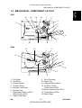
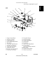
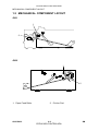
1.4 MECHANICAL COMPONENT LAYOUT
G031
12
13
14
15
1
2
3
11
4
5
6
7
9
10
8
G031V505.WMF
G032
15
12
1
2
3
11
4
5
6
7
10
1.
2.
3.
4.
5.
6.
7.
9
Exit Roller
Hot Roller
Pressure Roller
Transfer Roller
By-pass Feed Roller
By-pass Tray
Registration Rollers (G031)
Relay Roller (G032)
8. Paper Feed Roller
SM
8
G031V506.WMF
9. Toner Cartridge
10. Paper Tray
11. Polygonal Mirror Motor
12. 1st Mirror (G031)
F-theta Lens (G032)
13. Barrel Toroidal Lens (G031)
14. F-theta Mirror (G031)
15. Shield Glass
1-7
CÓPIA NÃO CONTROLADA
G031/G032
CÓPIA NÃO CONTROLADA
ELECTRICAL COMPONENT LAYOUT
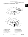
1.5 ELECTRICAL COMPONENT LAYOUT
G031
23
22
21
20
24
19
25
18
1
17
2
16
3
15
4
14
5
13
6
12
11
7
8
10
9
G031V501.WMF
1. Laser Synchronization Detector
2. Engine Control Board
3. Exhaust Fan Motor
4. High Voltage Supply Board
5. LD Drive Board
6. Main Motor
7. Tray Paper Feed Clutch
8. By-pass Feed Solenoid
9. Tray Paper Size Switch
10. Registration Sensor
11. By-pass Tray Paper Sensor
12. Registration Clutch
13. Toner Near-end Sensor
G031/G032
14. Tray Paper End Sensor
15. Fusing Thermistor
16. Tray Paper Near-end Sensor
17. Control Panel Board
18. Fusing Exit Sensor
19. Fusing Lamp
20. Thermofuse
21. Front Cover Safety Switch
22. Power Supply Unit
23. Main Switch
24. Polygonal Mirror Motor
25. Printer Control Board
1-8
CÓPIA NÃO CONTROLADA
SM
CÓPIA NÃO CONTROLADA
G032
19
18
Overall
Information
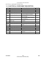
ELECTRICAL COMPONENT LAYOUT
20
17
21
16
1
15
14
2
13
12
3
4
5
11
10
9
8
6
7
G031V502.WMF
1. Engine Control Board
2. Exhaust Fan Motor
3. Power Supply Unit
4. High Voltage Supply Board
5. Main Motor
6. Tray Paper Feed Solenoid
7. By-pass Feed Solenoid
8. Toner Near-end Sensor
9. Registration Sensor
10. By-pass Tray Paper Sensor
11. Tray Paper End Sensor
SM
12. Fusing Exit Sensor
13. Fusing Thermistor
14. Control Panel Board
15. Fusing Lamp
16. Thermofuse
17. Front Cover Safety Switch
18. LD Drive Board
(with synchronization detector)
19. Main Switch
20. Polygonal Mirror Motor
21. Printer Control Board
1-9
CÓPIA NÃO CONTROLADA
G031/G032
CÓPIA NÃO CONTROLADA
ELECTRICAL COMPONENT DESCRIPTIONS
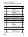
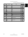
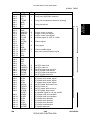
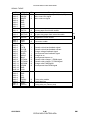
1.6 ELECTRICAL COMPONENT DESCRIPTIONS
Refer to the electrical component layout and the point-to-point diagram on the
waterproof paper in the pocket for the locations of these components.
Symbol
Description
Printed Circuit Boards
High Voltage Supply
PCB1 Board
PCB2
PCB3
PCB4
PCB5
Power Supply Unit
(PSU)
LD Drive Board
Control Panel
Engine Control Board
(ECB)
Printer Control Board
PCB6
Motors
M1
M2
M3
Main
Polygonal Mirror
Exhaust Fan
Sensors
S1
Fusing Exit
Tray Paper End
S2
S3
S4
Tray Paper Near-end
(G031)
By-pass Tray Paper
Registration
S5
S6
Toner Near-end
Switches
SW1
Main
Front Cover Safety
SW2
SW3
Tray Paper Size
(G031)
G031/G032
Note
Supplies high voltage to the drum
charge roller, development roller, and
transfer roller.
Provides dc power to the system and
ac power to the fusing lamp.
Controls the laser diode.
Controls the display panel, LED, and
the touch key pad.
Controls all base engine functions
either directly or through other control
boards.
Controls the PC interface, print image
processing, operation panel, and
other controller options.
Index No.
G031 G032
4
4
22
3
5
18
17
14
2
1
25
21
Drives the main body components.
Turns the polygonal mirror.
Removes heat from the printer.
6
24
3
5
20
2
Detects misfeeds.
Informs the CPU when the paper tray
runs out of paper.
Informs the CPU when the amount of
paper in the tray becomes low (50±30
sheets).
Informs the CPU when there is paper
on the by-pass tray.
Detects the leading edge of the paper
to determine when to stop the paper
feed clutch, and detects misfeeds.
Detects when toner is low.
18
12
14
11
16
—
11
10
10
9
13
8
Supplies power to the machine.
Cuts the +5VLD and +24 V dc power
lines and detects whether the front
cover is open or not.
Determines the size of paper in the
paper tray, based on the dial setting.
23
19
21
17
9
—
1-10
CÓPIA NÃO CONTROLADA
SM
CÓPIA NÃO CONTROLADA
Symbol
Description
Magnetic Clutches
Tray Paper Feed
MC1
(G031)
Registration
MC2
(G031)
Starts paper feed from the paper tray.
Lamps
L1
—
12
—
8
7
—
6
Heats the hot roller.
19
15
Monitors the temperature of the hot
roller.
15
13
Provides back-up overheat protection
in the fusing unit.
20
16
1
—
Starts paper feed from the by-pass
tray.
Starts paper feed from the paper tray.
Tray Paper Feed
(G032)
Fusing
Thermistors
Fusing
TH1
Thermofuses
Fusing
TF1
Index No.
G031 G032
7
Drives the registration rollers.
Solenoids
By-pass Feed
SOL1
SOL2
Note
Others
LSD1
SM
Laser Synchronization
Detector
(G031)
Detects the laser beam at the start of
the main scan.
1-11
CÓPIA NÃO CONTROLADA
G031/G032
Overall
Information
ELECTRICAL COMPONENT DESCRIPTIONS
CÓPIA NÃO CONTROLADA
PRINTING PROCESS
1.7 PRINTING PROCESS
6
1
OPC
5
–600 V
2
–100 V
4
3
–400 V
G031V507.WMF
G031/4 use an all-in-one type of toner cartridge that includes the drum, toner,
development roller, charge roller and other components.
1. DRUM CHARGE
In the dark, the charge roller gives a negative charge of –600 volts to the organic
photo-conductive (OPC) drum. The charge remains on the surface of the drum
because the OPC layer has a high electrical resistance in the dark.
2. LASER EXPOSURE
The processed print image data from the engine control board (ECB) is transferred
to the drum by a laser beam, which forms an electrical latent image on the drum
surface. The areas exposed by the laser beam drop to about –100 volts.
3. DEVELOPMENT
The magnetic development brush on the development roller approaches the latent
image on the drum. The development roller gives a negative bias of –400 volts to
the toner. Toner particles jump and electrostatically attach to the areas of the drum
surface where the laser reduced the negative charge on the drum.
G031/G032
1-12
CÓPIA NÃO CONTROLADA
SM
CÓPIA NÃO CONTROLADA
4. IMAGE TRANSFER
Paper is fed to the area between the drum surface and the transfer roller at the
proper time for aligning the print paper and the developed image on the drum
surface. Then, the transfer roller applies a positive current to the reverse side of the
paper (the size of the current depends on the resolution and the paper size). This
pulls the toner particles from the drum surface to the paper. At the same time, the
paper is attracted to the transfer roller.
5. PAPER SEPARATION
Paper separates from the drum as a result of the electrostatic attraction between
the paper and the transfer roller. The discharge plate helps separate the paper
from the drum.
6. CLEANING
The cleaning blade removes any toner remaining on the drum surface after the
image is transferred to the paper.
7. QUENCHING
There is no quenching mechanism.
SM
1-13
CÓPIA NÃO CONTROLADA
G031/G032
Overall
Information
PRINTING PROCESS
CÓPIA NÃO CONTROLADA
BOARD STRUCTURE
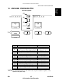
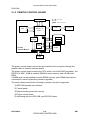
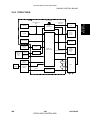
1.8 BOARD STRUCTURE
1.8.1 OVERVIEW
Motors &
Clutches
Laser
Diode
LD Drive
Board
Sensors
High Voltage
Supply Board
Video I/F
Printer
Control
Board
Control
Panel
Board
Engine
Control
Board
(ECB)
Paper Feed
Unit
+5 V/+24 V
Power
Supply
Unit
(PSU)
Fusing
Unit
G031V508.WMF
The engine control firmware controls the components connected to the engine
control board (ECB). The printer control board controls the control panel board.
The printer control board is also connected to the personal computer.
G031/G032
1-14
CÓPIA NÃO CONTROLADA
SM
CÓPIA NÃO CONTROLADA
1.8.2 MAJOR COMPONENTS
1. Engine Control Board (ECB)
This is the printer engine control board. It controls the following functions:
• Engine sequence
• Machine control, printer engine control
• Timing control for peripherals
• Video control
• Drive control for the sensors, motors, solenoids, and high voltage supply
board
• PWM control for edge smoothing (PWM is done on the printer control board)
2. Printer Control Board
This is the machine’s main control board. It controls the following functions:
• IEEE 1284 parallel port
• Edge smoothing and toner saving
• Engine control board
• Control panel board
• Interfacing with the HDD and NIB
3. LD Drive Board
This is the laser diode drive circuit board.
4. Power Supply Unit (PSU)
Provides dc power to the system and ac power to the fusing lamp.
5. High Voltage Supply Board
Supplies high voltage to the drum charge roller, development roller, and transfer
roller.
6. Fusing Unit
Fuses toner to the paper. The fusing lamp is controlled by the ECB.
7. Control Panel Board
Controls the display panel, the LED, and the touch keypad.
SM
1-15
CÓPIA NÃO CONTROLADA
G031/G032
Overall
Information
BOARD STRUCTURE
CÓPIA NÃO CONTROLADA
COMPARISON
1.9 COMPARISON
G031
G032
250 sheets
250 sheets
Standard Paper Tray
100 sheets
100 sheets
Standard Bypass Tray
500 sheets
500 sheets x 2
Optional Paper Tray
Envelope Feeder
10 envelopes
5 envelopes
Output Paper
250 sheets
Capacity
Input Paper Size
A3/11" x 17" ~ A5 (LEF)
A4 ~ A5 (LEF)
(Std./Opt. Tray)
Input Paper Size
A3/11" x 17" ~ B6 (SEF) free: A4/LG ~ B6 (SEF) free:
(By-pass Tray)
11.69" x 17" ~ 3.88" x 5.83"
8.5" x 14" ~ 3.88" x 5.83"
5.5 s or less
6.5 s or less
First Print Speed
(A4/LT ~ LEF, Standard Tray) (A4/LT ~ SEF, Standard Tray)
Duplex Printing
N/A
Memory
8 MB/40 MB
8 MB/40 MB
(Std./Max. with Opt.)
HDD (Option)
1.6 GB
PCL6 (35 Intellifonts, 10 True Type fonts and 1 bitmap font)
Fonts
PS2 (35 Adobe type 1 fonts)
Interface
Bi-directional parallel x 1
Ethernet (100 Base-Tx/10 Base-T for TCP/IP, IPX/SPX, Ether
Talk)
RS232C (Optional)
Warm-up Time
Utilities
Dimensions
(mm: W x D x H)
Less than 39 seconds: 23°C (73°F)
Aficio Manager
360 x 420 x 270 mm
450 x 420 x 270 mm
(with Std. Tray adjusted for A4) (with Std. Tray adjusted for A4)
450 x 555 x 270 mm
(with Std. Tray adjusted for A3)
Less than 15 kg (33 lb.)
Less than 12 kg (27 lb.)
Toner Cartridge: 14 K
Toner Cartridge: 8 K
Maintenance Kit: 80 K
Maintenance Kit: 60 K
Laser beam scanning & electrophotographic printing
Monocomponent development
Weight
Consumable Yield
PM Kit
Technology
Resolution
Continuous Print
Speed
Power Consumption
Drivers
Halftoning
Electrical Sorting
Diagnostic Test Mode
Test Print
Hex Dump List
Smoothing
Rotated Sorting
Toner Saving Mode
PDL Auto Change
Overlays (PCL)
Auto Cassette Change
Energy Saver
G031/G032
True 1,200 x 1,200 dpi (PCL6/PS)
600 x 600 dpi (PCL6/PCL5e/PS)
300 x 300 dpi (PCL5e/PS)
20 ppm (A4 SEF)
14 ppm (A4 LEF)
V20
250 sheets
100 sheets
500 sheets x 2 + 1,500 sheets
100 envelopes
Standard Output Tray: 400 sheets
External Tray: 100 sheets
A3/11" x 17" ~ A5/5.5" x 8.5" (LEF)
A3/11"x17" ~ A5/5.5" x 8.5" (SEF)
Option
8 MB/68 MB
PCL5e (35 Intellifont, 10 True Type
font and 1 bitmap font)
PS2 (35 Adobe type 1 fonts)
Bi-directional parallel (Standard)
Ethernet (10 Base 2/T for
IPX/SPX, TCP/IP, Apple Talk)
Token Ring (4 Mbps, 16 Mbps for
IPS/SPX, TCP/IP, Apple Talk)
Less than 60 seconds: 23°C (73°F)
530 x 625 x 472 mm
(with by-pass tray closed, without
the optional paper tray unit, without
options)
Less than 44.5 kg (99 lb.)
Laser beam scanning &
electrophotographic printing
Dualcomponent development
600 dpi, 400 dpi (available when
the PostScript option is installed),
300 dpi (simulated by doubling
pixel width and height at 600 dpi
resolution)
25 ppm (A4/LT LEF)
Max. 795 W
Max. 600 W
Max. 950 W
PCL version : Windows 3.1xx, 95,
PCL6/5e version : Windows 3.1x, 95(98), Windows NT 4.0
PS PPD: Windows 95 (98), Windows NT 4.0, Macintosh OS 7.5 Windows NT 3.51/4.0 (PCL & PS
version: Macintosh)
or later
P
P
P
P
P
P
N/A
P
P
P
P
P
P
P
P
P
P
P
N/A
P
P
P
P
P
1-16
CÓPIA NÃO CONTROLADA
P
P
P
P
P (N/A from Driver)
P
N/A
P
P
N/A
P
P
SM
CÓPIA NÃO CONTROLADA
DETAILED DESCRIPTIONS
CÓPIA NÃO CONTROLADA
CÓPIA NÃO CONTROLADA
CÓPIA NÃO CONTROLADA
CÓPIA NÃO CONTROLADA
PRINTING
2. DETAILED SECTION DESCRIPTIONS
2.1 PRINTING
PC AT
Compatible
Detailed
Descriptions
2.1.1 IMAGE DATA PATH
Macintosh
Ethernet
Parallel
NIB
Optional Bus I/F
CN.
LD Drive
Board
Drum
LD Unit
Gate
Array
ECB
ROCKY W
Printer Control Board
G031D502.WMF
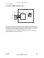
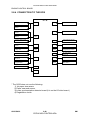
The printer control board receives the print data from the host computer (AT
compatible Windows PC or Macintosh).
• For the G031, the printer control board has two OBI (Optional Bus Interface)
connectors to connect a network interface board (NIB), RS232C interface, or
HDD unit.
• For the G032, the printer control board has one OBI connector.
The printer control board generates the print image data and sends it with
commands to the ECB (Engine Control Board).
The printer control board contains the image processing ASIC (ROCKY W). The
ROCKY W ASIC controls the image processing, IEEE1284 interface, DRAM, edge
smoothing, and toner saving. (ASIC: Application Specific Integrated Circuit)
The ECB contains a gate array. The gate array controls LD print timing control and
the serial interface to the printer control board.
Finally, the ECB sends the video data to the LD drive board.
SM
2-1
CÓPIA NÃO CONTROLADA
G031/G032
CÓPIA NÃO CONTROLADA
PRINTING
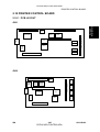
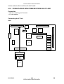
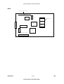
2.1.2 PRINTER CONTROL BOARD
Parallel I/F
32-bit Data
Address/Command
ECB
CPU
LD Unit
ROCKY W
(ASIC)
Option Board
NIB
Resident
DRAM
HDD
RS232C
Code
ROM
DIMM
Printer
Control Board
SIMM
G031D503.WMF
The printer control board receives the print data from the computer through the
parallel cable or network interface board.
The printer control board contains the CPU (which is a 64-bit RISC processor), the
ROCKY W ASIC, 8 MB of resident DRAM for main memory, and a 8 MB code
ROM.
A SIMM card can be installed for extra DRAM memory and a DIMM card can be
connected for service purposes (firmware upgrade).
The control board controls the following to produce the print image data.
1) IEEE1284 parallel port interface
2) Control panel
3) Edge smoothing and toner saving
4) Engine control board
5) Interfacing with the HDD, NIB, and RS232C board.
G031/G032
2-2
CÓPIA NÃO CONTROLADA
SM
CÓPIA NÃO CONTROLADA
PRINTING
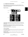
2.1.3 IMAGE DATA PROCESSIING
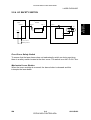
Edge smoothing and toner saving are performed by an ASIC (ROCKY W). The
edge smoothing and toner saving modes can be switched on/off with the machine’s
control panel or the printer driver.
Detailed
Descriptions
Edge Smoothing
Main Scan Direction
4/4
Fig. A
3/4
2/4
1/4
0
Sub Scan
Direction
Fig. B
Fig. C
G031D504.WMF
Jagged edges on characters as shown in the above illustration are reduced using
edge smoothing. Edge smoothing changes the laser pulse duration and position for
certain pixels.
Fig. A shows the four possible pulse durations, and Fig. B shows how the laser
pulse can be in one of three positions within the pixel. Fig. C shows an example of
how edge smoothing is used.
Edge smoothing is not done for 1,200-dpi printing.
Toner Saving Mode
Toner saving is done by reducing the number of black dots in the printed image. An
8 x 8 matrix filter is used.
As a result, less toner is used to create the latent image on the drum and black
areas print as gray.
The printer driver prevents edge smoothing and toner saving mode from being
used at the same time.
SM
2-3
CÓPIA NÃO CONTROLADA
G031/G032
CÓPIA NÃO CONTROLADA
PRINTING
2.1.4 HOST INTERFACE
Bi-directional Parallel Interface
G031D505.WMF
A 36-pin bi-directional parallel interface connector (female) is used.
The bi-directional parallel interface on the controller works in three modes;
Compatible, Nibble and ECP modes. These modes are standardized by IEEE
1284.
G031/G032
2-4
CÓPIA NÃO CONTROLADA
SM
CÓPIA NÃO CONTROLADA
LASER EXPOSURE
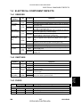
2.2 LASER EXPOSURE
This machine uses a laser diode to produce electrostatic images on an OPC drum.
The laser diode unit converts image data from the ECB into laser pulses, and the
optical components direct these pulses to the drum.
Exposure of the drum by the laser beam creates the latent image. The laser beam
makes the main scan while drum rotation controls the sub scan.
Strength of the beam output
Strength of the beam on the drum
Printing
G031
5 mW
0.636 mW
Binary (2 bits/pixel)
G032
5 mW
0.43 mW
Binary (2 bits/pixel)
There are two polygon motor speeds:
- G031 Resolution (dpi)
600
1,200
Modes
Motor Speed (rpm) Data Frequency (MHz)
300/600 dpi printing
22478.22
22.0926
1,200 dpi printing
22478.22
44.1851
- G032 Resolution (dpi)
600
1,200
Modes
Motor Speed (rpm) Data Frequency (MHz)
300/600 dpi printing
22377.62
15.0528
1,200 dpi printing
22377.62
30.1056
Differences between 1,200 dpi and 600 dpi printing
To produce 1,200 dpi, the machine uses a different data frequency for the main
scan and a different line speed for the sub scan, compared with 600 dpi printing.
For 1,200 dpi printing, the polygon motor works at the same speed as for 600 dpi
printing but the data frequency is twice as fast as in 600 dpi printing.
The paper at 1,200 dpi is fed at half the speed used for 600 dpi, as follows.
Paper feed line speed
600 dpi printing
92 mm/s
1,200 dpi printing
46 mm/s
The beam diameter for 1,200 dpi printing is the same as for 600 dpi printing.
SM
2-5
CÓPIA NÃO CONTROLADA
G031/G032
Detailed
Descriptions
2.2.1 OVERVIEW
CÓPIA NÃO CONTROLADA
LASER EXPOSURE
2.2.2 OPTICAL PATH
G031
[A]
[J]
[B]
[E]
[C]
[K]
[H]
[D]
[G]
[F]
G031D506.WMF
[C]
[A]
G032
[B]
[E]
[J]
[K]
[I]
[D]
G031D507.WMF
[A]:
[B]:
[C]:
[D]:
[E]:
[F]:
G031/G032
Polygonal Mirror
Cylindrical Lenses
LD Drive Board
Drum
LD Shutter
F-Theta Mirror
[G]: BTL (Barrel Toroidal Lens)
[H]: 1st Mirror
[I]: F-theta Lens
[J]: Laser Synchronization Detector
[K]: Shield Glass
2-6
CÓPIA NÃO CONTROLADA
SM
CÓPIA NÃO CONTROLADA
LASER EXPOSURE
The optical path from the laser diode to the drum is shown on the previous page.
G031
The laser beam goes to the F-theta mirror [F], 1st mirror [H] and BTL [G]. Then, the
beam reaches the drum [D] through the shield glass [K].
The beam reflected by the polygonal mirror writes the pixels of the latent image on
the drum. The F-theta mirror [F] ensures constant intervals between the pixels. The
BTL [G] corrects for irregularities in the polygonal mirror faces.
The laser synchronization detector [J] synchronizes the start of the main scan.
G032
The G032 has a shorter beam path than the G031.
The beam which is reflected by the polygonal mirror goes to the F-theta lens [I].
The beam reaches the drum [D] through the shield glass [K]. The F-theta lens [I]
does the functions of both the F-theta [F] mirror and the BTL [G].
The LD drive board for the G032 contains the laser synchronization detector.
SM
2-7
CÓPIA NÃO CONTROLADA
G031/G032
Detailed
Descriptions
The LD drive board [C] outputs the laser beam to the polygonal mirror [A] through
the cylindrical lenses [B], which focus the laser beam.
CÓPIA NÃO CONTROLADA
LASER EXPOSURE
2.2.3 AUTO POWER CONTROL (APC)
LD Drive Board
5V
CN1-7
LD
PD
VCC
APC
VIDEO
LD Driver
DPI select
LD OFF
G031D508.WMF
To prevent the intensity of the laser beam from changing because of temperature,
the machine monitors the laser beam with a photodiode (PD). The PD is enclosed
in the laser diode. The PD passes an electrical current to the LD driver IC and this
IC adjusts its output level to keep the laser diode output constant.
The laser diode power level is adjusted on the production line. Do not touch the
variable resistors on the LD unit in the field.
G031/G032
2-8
CÓPIA NÃO CONTROLADA
SM
CÓPIA NÃO CONTROLADA
LASER EXPOSURE
2.2.4 LD SAFETY SWITCH
Engine Control
Board
CN104-1
CN16-1
LD Drive Board
CN7-7
CN1-7
LD
Voltage
Regulator
+24V
CN103-1
PD
LD Driver
CN103-2
Front Cover
Safety Switch
G031D500.WMF
Front Cover Safety Switch
To ensure that the laser beam does not inadvertently switch on during servicing,
there is a safety switch located at the front cover. The switch is on the LD 24 V line.
Mechanical Laser Shutter
When the toner cartridge is removed, the laser shutter is released and this
interrupts the laser beam.
SM
2-9
CÓPIA NÃO CONTROLADA
G031/G032
Detailed
Descriptions
Power Supply
Unit
CÓPIA NÃO CONTROLADA
TONER CARTRIDGE
2.3 TONER CARTRIDGE
2.3.1 OVERVIEW
[A]
[B]
[C]
[D]
[E]
[I]
[H]
[G]
[F]
G031D509.WMF
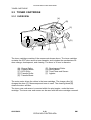
The toner cartridge consists of the components shown above. The toner cartridge
contains the OPC drum and the toner cassette, and includes the mechanisms for
drum charge, development, and cleaning. The drum is 30 mm in diameter.
[A]:
[B]:
[C]:
[D]:
[E]:
Charge Roller
Cleaning Blade
OPC Drum
Transfer Roller
Transfer Blade
[F]: Development Roller
[G]: Mixing Blade
[H]: Toner Near-end Sensor
[I]: Agitator
The main motor drives the rollers in the toner cartridge. The charge roller [A]
charges the drum [C]. Monocomponent toner is used. The cleaning blade [B]
cleans the drum surface.
The toner near end sensor is mounted within the print engine, under the toner
cartridge. The toner near end sensor can be seen with the toner cartridge removed.
G031/G032
2-10
CÓPIA NÃO CONTROLADA
SM
CÓPIA NÃO CONTROLADA
TONER CARTRIDGE
2.3.2 DRIVE
[B]
Detailed
Descriptions
[A]
[D]
[C]
G031D510.WMF
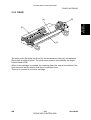
The main motor [B] drives the drum [C], the development roller [A], and agitators
[D] through a series of gears. The main motor speed is controlled by the engine
control board (ECB).
When a new cartridge is installed, the machine clears the near-end condition if the
toner near-end sensor detects that there is sufficient toner.
There is no counter for the toner cartridge.
SM
2-11
CÓPIA NÃO CONTROLADA
G031/G032
CÓPIA NÃO CONTROLADA
TONER CARTRIDGE
2.3.3 DRUM CHARGE
[A]
[B]
[E]
[C]
[D]
G031D511.WMF
This machine uses a drum charge roller system instead of a scorotron corona wire
system to charge the drum. The drum charge roller [A] always contacts the surface
of the drum [E] because of the charge roller pressure springs [C], and gives a
negative charge to the drum surface. While the drum is rotating, the drum charge
roller also turns because of friction between the roller and the drum.
The drum charge roller system generates less ozone than a scorotron corona wire
charge system. Due to this, there is no ozone filter in the machine.
The high voltage supply board gives a negative dc voltage to the drum charge
roller through the charge roller terminal [B], charge roller pressure spring [C], and
the charge roller bushing [D]. This gives the drum surface a negative charge of 600 V.
The high voltage supply board also applies 2 kVp-p 1 kHz ac to the charge roller.
This ac removes any remaining voltage on the drum.
The toner cartridge has no cleaning pad, temperature control, or contact
mechanism for the drum charge roller. The material of the drum charge roller
allows a simple mechanism. The drum charge roller is part of the toner cartridge,
so when the toner runs out, the drum charge roller is changed at the same time.
This happens before the drum charge roller gets dirty.
G031/G032
2-12
CÓPIA NÃO CONTROLADA
SM
CÓPIA NÃO CONTROLADA
TONER CARTRIDGE
2.3.4 DEVELOPMENT
Overview
[A]
[G]
[B]
[E]
[D]
[C]
G031D509.WMF
This machine uses monocomponent toner. The G031 has two agitators [F] in the
toner cartridge(shown above). The G032 has one agitator.
The agitator(s) [F] and the mixing blade [D] mix the toner in the toner cartridge and
transport it to the development roller [C]. Friction between the transported toner
and the doctor blade [A] gives the toner a negative charge.
Internal permanent magnets in the development roller attract the toner to the
development roller sleeve. The doctor blade trims the toner to the desired
thickness on the development roller sleeve. The development roller does not
contact the drum [G]. There is a small gap between the toner on the surface of the
development roller sleeve and the drum. Toner jumps across this gap to develop
the latent image.
The development bias consists of ac and dc components. The ac component
improves the transfer of toner.
The transfer blade [B] is charged to the same voltage as the development bias.
This helps to keep the toner on the drum.
The toner near-end sensor [E] is located under the toner cartridge. The sensor
monitors the toner concentration through the plastic housing of the toner cartridge.
SM
2-13
CÓPIA NÃO CONTROLADA
G031/G032
Detailed
Descriptions
[F]
CÓPIA NÃO CONTROLADA
TONER CARTRIDGE
Toner Near-End Sensor
The toner near-end sensor monitors the toner concentration by checking the
magnetic field strength.
When the reading goes down to a threshold value, the machine enters the nearend condition. There is no toner end condition (the user replaces the cartridge
when the print quality has become unacceptable). The threshold value cannot be
changed.
No adjustment is required after the sensor is replaced.
Toner Supply
The toner in the toner cartridge is mixed by the agitator(s) and mixing blade. The
toner near-end sensor is not used to control toner supply. When the machine is
turned on or the front cover is closed, the agitator(s) and the mixing blade rotate to
mix the toner for a brief period.
Development Bias
The high voltage supply unit gives the development roller a charge of –400 V dc
and an ac component of 1.8 kVp-p 1.8 kHz ac is also used. To prevent toner from
transferring to non-image areas on the drum, the development bias is different for
image areas and non-image areas.
G031/G032
2-14
CÓPIA NÃO CONTROLADA
SM
CÓPIA NÃO CONTROLADA
TONER CARTRIDGE
2.3.5 DRUM CLEANING
[D]
[C]
Detailed
Descriptions
[A]
[B]
G031D512.WMF
The cleaning blade [A] removes any toner remaining on the drum after the image is
transferred to the paper. The toner remaining on the drum is scraped off by the
cleaning blade and transferred to the collection area. The mylar sheet [B] prevents
the toner from dropping out of the cleaning unit.
The toner cartridge in the commercial toner cartridge has a toner collection coil [C]
and scraper [D]. These improve the collection of waste toner.
There is no toner recycling mechanism.
SM
2-15
CÓPIA NÃO CONTROLADA
G031/G032
CÓPIA NÃO CONTROLADA
IMAGE TRANSFER AND PAPER SEPARATION
2.4 IMAGE TRANSFER AND PAPER SEPARATION
2.4.1 OVERVIEW
[C]
[A]
[B]
G031D513.WMF
The machine uses a transfer roller [A] which touches the surface of the drum [B].
The high voltage supply unit supplies a positive current to the transfer roller. A
feedback circuit inside the machine automatically keeps the transfer current
constant.
The transfer current depends on the paper size. For A3/11” x 17” paper in the
G031, 7µA is supplied, and for A4/LT paper in the G032, 6µA is supplied (for 600
dpi resolution in both of these cases).
The transfer roller attracts the toner from the drum onto the paper.
Drive from the drum through a gear drives the transfer roller.
The discharge plate [C] and the curvature of the drum helps the paper to separate
from the drum. The discharge plate is connected to ground.
G031/G032
2-16
CÓPIA NÃO CONTROLADA
SM
CÓPIA NÃO CONTROLADA
IMAGE TRANSFER AND PAPER SEPARATION
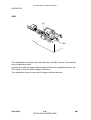
2.4.2 TRANSFER ROLLER CLEANING
During transfer roller cleaning, the high voltage supply unit supplies a negative
cleaning bias to the transfer roller. The negatively charged toner on the transfer
roller is then transferred back to the drum. Then a positive cleaning bias is applied
to the transfer roller to push back to the drum any toner which was positively
charged by the transfer roller.
The machine goes through the cleaning mode in the following conditions:
• After a printer jam has been cleared.
• Just after the power is switched on.
• After 10 sheets of paper have been printed and the print job has finished.
SM
2-17
CÓPIA NÃO CONTROLADA
G031/G032
Detailed
Descriptions
If the paper size is smaller than the printed image, or if a paper jam occurs during
printing, toner may be transfered to the roller surface. To prevent this toner from
transferring to the back side of the printouts, the transfer roller has to be cleaned
before the next printing run.
CÓPIA NÃO CONTROLADA
PAPER FEED
2.5 PAPER FEED
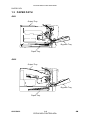
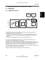
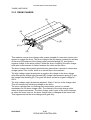
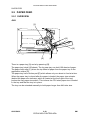
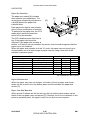
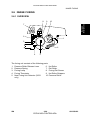
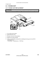
2.5.1 OVERVIEW
G031
[C]
[D]
[B]
[A]
[E]
G031D514.WMF
There is a paper tray [A] and a by-pass tray [B].
The paper tray holds 250 sheets. The by-pass tray can hold 100 sheets of paper.
The paper feed roller [C] drives the top sheet of paper from the paper tray to the
registration rollers [D].
The paper tray has a friction pad [E] which allows only one sheet to feed at a time.
When the paper tray is closed after the paper is loaded, the paper size actuator
(behind the paper size indicator, which is located at the front right of the tray)
pushes the tray paper size switch. This informs the CPU what paper size is loaded
in the tray and that the tray is in place.
The tray can be extended manually to hold paper longer than A4/Letter size.
G031/G032
2-18
CÓPIA NÃO CONTROLADA
SM
CÓPIA NÃO CONTROLADA
PAPER FEED
Detailed
Descriptions
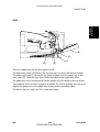
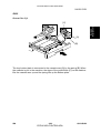
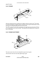
G032
[B]
[D]
[C]
[A]
[E]
G031D515.WMF
There is a paper tray [A] and a by-pass tray [B].
The paper tray holds 250 sheets. The by-pass tray can hold 100 sheets of paper.
The paper feed roller [C] drives the top sheet of paper from the paper tray to the
relay roller [D]. Then the relay roller feeds the paper to the registration area.
The paper tray has a friction pad [E] which allows only one sheet to feed at a time.
This machine does not have a paper size switch. So, before printing, the user must
register the paper size in the paper tray at the printer’s operation panel.
The built-in tray can only hold A4 or letter size paper.
SM
2-19
CÓPIA NÃO CONTROLADA
G031/G032
CÓPIA NÃO CONTROLADA
PAPER FEED
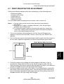
2.5.2 PAPER TRAY
G031
Tray Extension
The tray can be extended manually
to hold paper longer than A4/Letter
size. The default setting of the tray
length is for short paper. To use
longer paper, release the catches
[A] at both sides, then extend the
tray and re-lock the catches.
[A]
The paper sizes in the table given
below can be used.
G031D516.WMF
Tray mode
Possible Paper Sizes
Short
A5 Landscape, B5 Landscape, A4 Landscape, 71/4" x 101/2" Landscape,
(default)
81/2" x 11" Landscape, 81/2" x 11" Portrait, A4 Portrait
81/2" x 13" Portrait, 8" x 13" Portrait, 81/4" x 13" Portrait, 81/2" x 14"
Long
Portrait, B4 Portrait, A3 Portrait, 11" x 17" Portrait
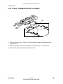
Bottom Plate Lift
[C]
The tray bottom plate [B] is connected
to the cassette arms [C] by springs
[D]. When the cassette is put in the
machine, the slopes of the guide
blocks [E] on the machine lift the
cassette arms up and the springs
keep the stack of paper at the correct
height. When the paper is used up,
the springs pull the tray bottom plate
up as shown in the picture.
[E]
[D]
[B]
G031/G032
2-20
CÓPIA NÃO CONTROLADA
G031D517.WMF
SM
CÓPIA NÃO CONTROLADA
PAPER FEED
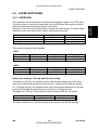
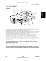
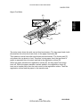
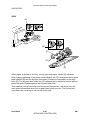
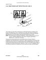
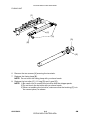
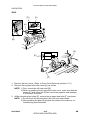
Paper Feed Drive
[E]
Detailed
Descriptions
[F]
[A]
[B]
[C]
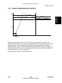
[D]
G031D518.WMF
The main motor drives the pick-up and feed mechanism. The tray paper feed clutch
[A] transfers drive from the main motor to the paper feed roller [B].
This machine uses a feed roller and friction pad mechanism. The friction pad [C]
only allows the top sheet to feed. Therefore, during paper feed, the top sheet of
paper is separated from the stack and fed to the registration rollers [D].
When the paper actuates the registration sensor [E], the tray paper feed clutch
turns off. When the paper reaches a certain position, the registration clutch [F]
turns on to transfer drive from the main motor to the registration rollers. Then the
registration rollers feed the paper to the transfer area.
SM
2-21
CÓPIA NÃO CONTROLADA
G031/G032
CÓPIA NÃO CONTROLADA
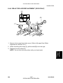
PAPER FEED
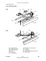
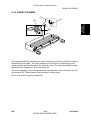
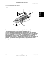
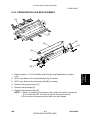
Paper Size Detection
[A]
The paper size switch [A] includes
three sensors (microswitches). The
sensors are actuated by actuators on
a dial [B] behind the paper size
indicator plate.
[C]
[D]
Each paper size has its own actuator,
with a unique combination of notches.
To determine the paper size, the CPU
reads which switches have been
turned off by the actuator.
[B]
The CPU disables paper feed from a
G031D519.WMF
tray if the paper size cannot be
detected. If the paper size actuator is
broken, or if there is no tray installed, the printer control board recognizes that the
paper tray is not installed.
When the paper size actuator is at the "@" mark, the paper tray can be set up to
accommodate one of a wider range of paper sizes by using a user tool at the
machine’s operation panel.
Models
North America
81/2" x 14" Portrait
A4 Landscape
81/2" x 11" Portrait
Europe
A5 Landscape
A4 Landscape
A4 Portrait
81/2" x 13" Portrait
81/2" x 11" Landscape
11" x 17" Portrait
81/2" x 13" Portrait
81/2" x 11" Landscape
A3 Portrait
@
@
Left
On
On
On
Off
Off
On
Off
Switch Location
Center
Right
On
On
Off
Off
On
Off
On
On
On
Off
Off
On
Off
On
On: Pushed Off: Not Pushed
Paper End Detection
When the paper tray runs out of paper, the feeler of the tray paper end sensor
drops into the cutout in the tray bottom plate and this activates the paper end
sensor [C].
Paper Near End Detection
When almost 50 sheets are left on the tray, the tray bottom plate pushes up the
feeler of the tray paper near end sensor [D]. However, there is no indication on the
printer’s operation panel; the signal is only for use by the host computer.
G031/G032
2-22
CÓPIA NÃO CONTROLADA
SM
CÓPIA NÃO CONTROLADA
PAPER FEED
G032
Bottom Plate Lift
[A]
[B]
G031D520.WMF
The tray bottom plate is connected to the cassette arm [A] by the spring [B]. When
the cassette is put in the machine, the slope of the guide block [C] on the machine
lifts the cassette arm up and the spring lifts up the bottom plate.
SM
2-23
CÓPIA NÃO CONTROLADA
G031/G032
Detailed
Descriptions
[C]
CÓPIA NÃO CONTROLADA
PAPER FEED
Paper Feed Drive
[B]
[D]
[E]
[C]
[F]
[A]
[G]
[I]
[H]
G031D521.WMF
The main motor drives the pick-up and feed mechanism through the paper pick-up
drive gear [D].
To pick up paper, the tray paper feed solenoid [A] turns on and the gear stopper [B]
comes off the paper feed roller gear [C]. This gear does not move immediately,
because the gap in the teeth prevent it from engaging the drive gear [D]. It is first
turned clockwise by a spring until its teeth engage with the drive gear, which now
drives the paper feed roller [E].
At the same time, the cam behind the paper feed roller gear moves the stopper
release lever [G], and this releases the bottom plate stopper [H]. The bottom plate
can then lift the top of the paper stack to the correct height for paper feed.
This machine uses a feed roller and friction pad mechanism. The friction pad [F]
only allows the top sheet to feed to the relay roller [I].
After one turn, the paper feed roller gear stops because the part of the gear without
teeth is now back at the starting position, opposite the pick-up drive gear. The gear
stopper and bottom plate stopper also return to their previous positions
Then the relay rollers feed the paper to the transfer area.
NOTE: If the gear stopper comes off the paper feed roller gear as a result of shock
or vibration and paper is placed in the tray, the machine starts to feed
paper as soon as it is turned on. To fix this problem, remove all paper from
the paper tray then turn on the machine.
Paper End Detection
This is the same as for the G031. There is no near-end detection.
G031/G032
2-24
CÓPIA NÃO CONTROLADA
SM
CÓPIA NÃO CONTROLADA
PAPER FEED
2.5.3 BY-PASS TRAY
G031
Detailed
Descriptions
[A]
[B]
[F]
[G]
[C]
G031D522.WMF
[D]
[E]
G031D523.WMF
When paper is placed on the tray, the by-pass tray paper feeler [A] is pushed up
and the actuator leaves the by-pass tray paper sensor [B].
After image processing in the printer control board, the CPU energizes the by-pass
feed solenoid and the by-pass feed roller [C] starts to feed paper to the registration
roller [D]. The by-pass feed roller has two cams [E] and these cams release the bypass tray bottom plate to press the stack of paper against the by-pass feed roller.
This machine uses a feed roller and friction pad mechanism, with drive from the
main motor transmitted when the by-pass feed clutch turns on. The friction pad
only allows the top sheet to feed to the registration rollers.
When the paper leading edge activates the registration sensor [F], the registration
clutch [G] turns on.
SM
2-25
CÓPIA NÃO CONTROLADA
G031/G032
CÓPIA NÃO CONTROLADA
PAPER FEED
G032
[A]
[B]
G031D524.WMF
[C]
[D]
[E]
G031D525.WMF
When paper is placed on the tray, the by-pass tray paper sensor [A] activates.
After image processing in the printer control board, the CPU energizes the by-pass
feed solenoid [B] and the by-pass feed roller [C] starts to feed paper to the relay
roller [D]. The by-pass feed roller cam [E] releases the by-pass tray bottom plate to
press the stack of paper against the by-pass feed roller.
This machine uses a feed roller and friction pad mechanism, with drive from the
main motor transmitted when the by-pass feed clutch turns on. The friction pad
only allows the top sheet to feed to the relay roller.
G031/G032
2-26
CÓPIA NÃO CONTROLADA
SM
CÓPIA NÃO CONTROLADA
PAPER FEED
2.5.4 PAPER REGISTRATION
G031
[B]
Detailed
Descriptions
[A]
[D]
[C]
G031D518.WMF
Main motor rotation is transmitted to the registration clutch gear [A].
The registration sensor [B] is just before the registration rollers [C].
When the paper leading edge activates the registration sensor, the registration
clutch [D] turns off and the registration rollers stop turning. However, the tray paper
feed roller clutch stays on for a bit longer. This delay allows time for the paper to
press against the registration rollers and buckle slightly to correct skew. The
registration clutch energizes at the proper time to align the paper with the image on
the drum. The registration rollers feed the paper to the image transfer section.
The registration sensor is also used for paper misfeed detection.
SM
2-27
CÓPIA NÃO CONTROLADA
G031/G032
CÓPIA NÃO CONTROLADA
PAPER FEED
G032
[A]
[B]
G031D526.WMF
The registration sensor [A] is just after the relay roller [B]. However, this machine
has no registration roller.
A certain time after the paper leading edge activates the registration sensor, the
CPU starts to write the latent image on the drum.
The registration sensor is also used for paper misfeed detection.
G031/G032
2-28
CÓPIA NÃO CONTROLADA
SM
CÓPIA NÃO CONTROLADA
IMAGE FUSING
2.6 IMAGE FUSING
2.6.1 OVERVIEW
8
9
10
Detailed
Descriptions
7
6
1
5
2
4
3
G031D527.WMF
The fusing unit consists of the following parts.
1.
2.
3.
4.
5.
SM
Pressure Roller Release Lever
Pressure Spring
Fusing Lamp
Fusing Thermistor
New Fusing Unit Detector (G031
only)
6. Hot Roller
7. Exit Roller
8. Fusing Exit Sensor
9. Hot Roller Strippers
10. Pressure Roller
2-29
CÓPIA NÃO CONTROLADA
G031/G032
CÓPIA NÃO CONTROLADA
IMAGE FUSING
2.6.2 FUSING
[D]
[A]
[C]
[B]
G031D528.WMF
After the image has been transferred, the paper enters the fusing unit. The image
is fused to the paper by applying heat and pressure through the combination of hot
roller [A], the fusing lamp [B], and the pressure roller.
The CPU monitors the hot roller temperature through the fusing thermistor [C] that
is in contact with the hot roller surface. The thermofuse [D] protects the fusing unit
from overheating.
2.6.3 FUSING UNIT DRIVE
[B]
[A]
G031D529.WMF
The main motor drives the hot roller [A] through a train of gears.
The hot roller drives the exit roller [B] through a gear.
G031/G032
2-30
CÓPIA NÃO CONTROLADA
SM
CÓPIA NÃO CONTROLADA
IMAGE FUSING
2.6.4 PRESSURE ROLLER/PAPER EXIT
Detailed
Descriptions
[C]
[A]
[B]
G031D530.WMF
During printing, the pressure roller [A] is pressed against the hot roller [B] by
springs.
The hot roller strippers [C] separate the paper from the hot roller and direct it to the
exit roller. Then the exit roller feeds the paper to the paper tray.
2.6.5 FUSING UNIT DRIVE RELEASE
[A]
G031D531.WMF
When the pressure roller release levers [A] are pushed down, the pressure roller
moves away so that jammed paper can be removed.
SM
2-31
CÓPIA NÃO CONTROLADA
G031/G032
CÓPIA NÃO CONTROLADA
IMAGE FUSING
2.6.6 NEW FUSING UNIT DETECTION (G031 ONLY)
[D]
[C]
[A]
[B]
G031D532.WMF
The fusing unit in the G031 maintenance kit has this detection mechanism (the
fusing unit obtained as a service part does not). When the fusing unit has been
replaced, the CPU detects the new unit and automatically removes the “Replace
Maintenance Kit” from the display and resets the maintenance counter.
NOTE: The G032 doesn’t have this mechanism, so after replacing the fusing unit,
clear the “Replace Maintenance Kit” status using the “User Menu –
Maintenance – PM Clear” procedure.
There are two terminals [A] at the rear left side of the fusing unit. Before
installation, these terminals are in contact [C]. When the machine is turned on after
installing the new fusing unit, the projection on the ring [B] attached to the left end
of the hot roller disconnects the terminals [D]. When the CPU detects the change in
the signal from these terminals from ‘shorted’ to ‘open’, the CPU recognizes that a
new fusing unit has been installed and it then resets the counter and the display.
G031/G032
2-32
CÓPIA NÃO CONTROLADA
SM
CÓPIA NÃO CONTROLADA
IMAGE FUSING
2.6.7 FUSING TEMPERATURE CONTROL
(°C)
200
printing [B]
Detailed
Descriptions
standby [A]
170
100
2 minutes
Main SW on
G031D533.WMF
When the main switch turns on, the CPU turns on the fusing lamp. When the
thermistor detects the ‘ready to print’ temperature (170°C), the machine can start to
print at any time. The lamp stays on until the thermistor detects the standby
temperature [A]. Then, the CPU maintains this temperature using on-off control. To
start printing, the CPU raises the temperature to the printing temperature [B] and
maintains it as shown on the next page.
In energy saver mode, the fusing lamp is off.
SM
2-33
CÓPIA NÃO CONTROLADA
G031/G032
CÓPIA NÃO CONTROLADA
IMAGE FUSING
The CPU controls the temperature as shown in the following tables to keep the
fusing lamp at the appropriate temperature for each condition.
G031
Condition
Ready to print
Standby mode
Printing
Normal paper
(600 dpi) Thick paper (> 155 g/m², 41 lb)
Printing
Normal paper
(1,200 dpi) Thick paper (> 155 g/m², 41 lb)
Power on →
Within 2 minutes
170°C
185°C
195°C
195°C
165°C → 160°C *
165°C
After 2 minutes
170°C
175°C
185°C
195°C
160°C → 155°C *
160°C
*: After 26 seconds at 1,200 dpi using normal paper, the temperature is reduced.
G032
Condition
Ready to print
Standby mode
Printing
Normal paper
(600 dpi) Thick paper (> 155 g/m², 41 lb)
Printing
Normal paper
(1,200 dpi) Thick paper (> 155 g/m², 41 lb)
Power on →
Within 2 minutes
170°C
175°C
185°C
185°C
150°C → 145°C *
150°C
After 2 minutes
170°C
165°C
175°C
185°C
145°C → 140°C *
145°C
*: After 15 seconds at 1,200 dpi using normal paper, the temperature is reduced.
G031/G032
2-34
CÓPIA NÃO CONTROLADA
SM
CÓPIA NÃO CONTROLADA
IMAGE FUSING
Detailed
Descriptions
[B]
[A]
G031D528.WMF
The fusing temperature is controlled using the fusing thermistor [A].
The CPU checks the output from the fusing thermistor once a second. The CPU
compares the current and previous temperature, then decides the power-on ratio
for the next second. To maintain the target temperature, the CPU controls the
fusing lamp power-on ratio as shown in the following table.
Current minus Target
Previous minus Current Over –3°C Within –3°C
0
Within +3°C Over +3°C
100%
60%
60%
60%
0%
Over –3°C
100%
60%
60%
40%
0%
Within –3°C
0
100%
60%
60%
40%
0%
100%
60%
60%
40%
0%
Within +3°C
100%
60%
0%
0%
0%
Over +3°C
Ratio (%): The proportion of time that the fusing lamp power is on
2.6.8 OVERHEAT PROTECTION
If the hot roller temperature becomes greater than 230°C for more than 1 second,
the CPU cuts off the power to the fusing lamp. At this time, SC543 will be
generated.
Even if the thermistor overheat protection fails, there is a thermofuse in series with
the common ground line of the fusing lamp. If the temperature of the thermofuse
[B] reaches 169°C, the thermofuse opens, removing power from the fusing lamp.
At this time, the printer stops operating.
SM
2-35
CÓPIA NÃO CONTROLADA
G031/G032
CÓPIA NÃO CONTROLADA
IMAGE FUSING
2.6.9 ENERGY SAVER MODE
When the machine is not used, the energy saver feature reduces power
consumption by switching off the fusing lamp.
Entering Energy Saver Mode
Energy saver mode starts after the machine has been idle for a certain time. This
time is specified by the user. The following choices are available.
• Off (energy saver mode never activates)
• 15 minutes
• 30 minutes (default)
• 1 hour
• 2 hours
• 3 hours
This feature is adjusted using the Job Control menu at the printer’s operation
panel.
NOTE: When the machine is in energy saver mode, the CPU turns off the fusing
lamp. Therefore, the time from the print start command to the start of
printing is longer than in normal standby mode.
Leaving Energy Saver Mode
The machine leaves energy saver mode when one of the following happens.
• Print command received from the PC
• Front cover opened and closed
• Paper tray pulled out and replaced
• Any operation panel keys pressed
G031/G032
2-36
CÓPIA NÃO CONTROLADA
SM
CÓPIA NÃO CONTROLADA
COVER OPEN DETECTION
2.7 COVER OPEN DETECTION
Detailed
Descriptions
2.7.1 FRONT COVER LOCK
[A]
[B]
G031D534.WMF
There is a hook [A] at the front and rear of the machine. When the front cover is
closed, the hooks catch the lock levers [B].
To open the front cover, push the cover open levers at both sides of the front
cover.
2.7.2 FRONT COVER SAFETY SWITCH
[C]
[A]
[B]
G031D535.WMF
When the user opens the front cover, the safety switch release lever [A] moves and
the safety switch release cam [B] rotates as shown in the picture. Then the front
cover safety switch [C] turns off.
If the front cover safety switch turns off, the +24V line from PSU to ECB is cut. As a
result, the power for the LD driver is cut.
SM
2-37
CÓPIA NÃO CONTROLADA
G031/G032
CÓPIA NÃO CONTROLADA
COVER OPEN DETECTION
2.7.3 REMOVING THE FUSING UNIT
[C]
[A]
[D]
[E]
[B]
G031D536.WMF
When the fusing unit is not in the machine [A], the stopper [B] blocks the safety
switch release lever [C]. Therefore, the front cover cannot be closed.
When the fusing unit is installed properly [D], the projection on the fusing unit [E]
lifts up the stopper. Therefore, the safety switch release lever can pass and the
front cover can be closed.
G031/G032
2-38
CÓPIA NÃO CONTROLADA
SM
CÓPIA NÃO CONTROLADA
ENGINE CONTROL BOARD
2.8 ENGINE CONTROL BOARD
2.8.1 PCB LAYOUT
EPROM
TB1
Gate
Array
EEPROM
SRAM
CN11 CN12 CN13 CN14
CN2
CN10
CN9
CPU
H8/3002
Engine
I/F
CN8
CN1
CN7
CN4
CN6
Detailed
Descriptions
CN3
CN5
CN15
CN16
G031D540.WMF
SM
2-39
CÓPIA NÃO CONTROLADA
G031/G032
CÓPIA NÃO CONTROLADA
ENGINE CONTROL BOARD
2.8.2 DEVICES
The engine control board controls the printer engine system.
Devices
CPU
Gate Array (GAZELLE)
EPROM
EEPROM
SRAM
TB1
G031/G032
Functions
16-bit microprocessor
Internal RAM: 512 bits
Serial communication control for I/F controller
Laser printing control
Power width modulation (PWM) timer.
LD driver sample hold function
Pattern generation
Fusing unit control timer
I/O port
128 K engine firmware ROM
Service maintenance information (counters, registration,
etc.) 1 kbit
32 KB
The test pattern will be printed when TB1 is shorted.
2-40
CÓPIA NÃO CONTROLADA
SM
CÓPIA NÃO CONTROLADA
ENGINE CONTROL BOARD
2.8.3 STRUCTURE
ECB
Thermistor
Sensors
EPROM
CPU
(H8/3002)
SRAM
Video I/F
EEPROM
Motors
Clutches
Fan
Motor
Clutch
Driver
Fusing Control
Driver
High
Voltage
Supply
Unit
Sensors
Sync.
Detector
Laser
Diode
Printer
Control
Board
Sensors
GAZELLE
(Video & I/O)
Optional
Paper
Feed
Unit
Fusing
Unit
+5V
PSU
LD Drive
Board
+24V
+5VS
Regulator
G031D541.WMF
SM
2-41
CÓPIA NÃO CONTROLADA
G031/G032
Detailed
Descriptions
XTL: 16MHz
Address/Data
Bus
CÓPIA NÃO CONTROLADA
ENGINE CONTROL BOARD
2.8.4 CONNECTION TO THE ECB
ECB
Registration Sensor
CN3
CN1
Printer Control Board
CN16
PSU
CN15
High Voltage Supply
Unit
By-pass Paper End
Sensor
1st Tray Paper End
Sensor
*Paper Near-end
Sensor
CN4
*1st Tray Paper Size
Sensor
Toner Near-end
Sensor
CN5
CN14
Exhaust Fan Motor
Fusing Unit
CN6
CN13
*Registration Clutch
CN12
By-pass Feed
Solenoid
CN11
Paper Feed Clutch
CN10
Main Motor
LD Drive Board
*Laser Synch.
Detector
CN7
Polygon Motor
2nd/3rd PFU
CN8
CN9
G031D542.WMF
* The G032 does not use the following:
1) 1st paper size sensor
2) Paper near end sensor
3) Laser synchronization detector board (It is on the LD drive board.)
4) Registration clutch
G031/G032
2-42
CÓPIA NÃO CONTROLADA
SM
CÓPIA NÃO CONTROLADA
CN
CN1
CN3
CN4
CN5
CN6
CN7
CN8/9
CN10
CN11
CN12
CN13
CN14
CN15
CN16
SM
Description
Supplies +5 V to the printer control board. Also passes the video, engine
control, and the serial data signals
Signals from the registration sensor and by-pass paper end sensor
Signals from the 1st tray paper size and paper end sensors. For the
G031, also from the 1st tray paper near-end sensor.
Signal from the toner near-end sensor
Signals from the fusing unit thermistor (hot roller temperature) and the fusing
exit sensor.
Determines whether a 120 V or 200 V fusing unit is installed.
Automatic laser power control signal, video signal
Polygon motor on/off and rotation speed control
Detects the polygon motor lock condition.
Signal from the laser synchronization detector (The detector is built into the LD
drive board in the G032.)
Signals from the sensors in the optional paper feed units. Control for the
clutches and motors
Main motor on/off control, and main motor lock detection
Turns the 1st tray paper feed clutch/solenoid on/off
Turns the by-pass tray solenoid on/off
Turns the registration clutch on/off (only used for G031)
Turns the fan motor on/off and controls the fan motor speed.
Controls the charge voltage, development bias, and transfer roller bias.
+5 V and +24 V from the PSU. The interlock switch cuts the +24 V when the
front cover is opened.
Controls the fusing unit safety relay
Turns the power to the fusing unit on/off.
2-43
CÓPIA NÃO CONTROLADA
G031/G032
Detailed
Descriptions
ENGINE CONTROL BOARD
CÓPIA NÃO CONTROLADA
SIGNAL TABLE
2.9 SIGNAL TABLE
CN
CN1-A1
CN1-A2
CN1-A3
CN1-A4
CN1-A5
CN1-A6
CN1-A7
CN1-A8
CN1-A9
Signal
GND
GND
+5V
N.C
FGATE
PPRDY
/RDY
/SBSY
/SCLK
I/O
CN1-A10
CN1-B1
CN1-B2
CN1-B3
CN1-B4
CN1-B5
CN1-B6
CN1-B7
CN1-B8
CN1-B9
/STS
/VIDEO
GND
+5V
+5V
/BD
CPRDY
/PRINT
/CBSY
/CCLK
O
I
CN1-B10
CN2-1
CN2-2
CN2-3
CN2-4
CN3-1
CN3-2
CN3-3
CN3-4
CN3-5
CN3-6
CN4-1
CN4-2
CN4-3
CN4-4
CN4-5
CN4-6
CN4-7
CN4-8
CN5-1
CN5-2
CN5-3
CN5-4
CN6-1
CN6-2
/CMD
+5V
/RXD
/TXD
GND
GND
/REGST
+5V
GND
MPEND
+5V
GND
FPEND
GND
/FPNE
FPS0
FPS1
GND
FPS2
GND
/TEND
N.C
+5V
GND
/FSET0
I
Main scan synchronization signal.
Controller power ready
Printing request
Enables communication from the controller
Synchronization clock for serial communication
from the controller
Serial command from the controller
I
O
Designer use only
Designer use only
I
Registration sensor signal
I
By-pass tray paper end signal
G031/G032
O
O
O
O
O
O
I
I
I
I
Description
Sub scan data printing area signal
Printing ready
Printing enable
Enables communication with the controller
Synchronization clock for serial communication
with the controller
Serial status to the controller
Video data
P3
I
1st tray paper end signal
I
I
I
1st tray paper near-end signal
1st tray paper size signal
1st tray paper size signal
I
1st tray paper size signal
I
Toner near-end condition
I
Fusing unit 100V/200V selection
2-44
CÓPIA NÃO CONTROLADA
P4
SM
CÓPIA NÃO CONTROLADA
SIGNAL TABLE
CN9-9
CN9-10
CN9-11
CN9-12
CN9-13
CN9-14
CN9-15
SM
Signal
/FSET1
/FSET2
+5V
FTEMP
GND
/EXIT
+5V
+24V
GND
XSMSTA
/SMLOK
SMCK
CHLDP
+5VS
APCSH
GND
/VD
GND
/LD EN
/DETP
+5V
GND
+24V
GND
GND
+5V
SNDCK
XSNDFD
XSNDCL
SPSEN
EPEND
/OTSET
CHG2
OPS0
OPS1
OPS2
TRDCK
/TRDFD
/TRDCL
TPSEN
/FCSET
OPNE0
OPNE1
OPS0
OPS1
OPS2
OPEND
XOTSET
I/O
I
I
Description
Fusing unit 100V/200V selection
Fusing unit 100V/200V selection
I
Fusing unit temperature detection (analog)
I
Fusing exit sensor
P3
P4
I
O
I
O
O
Polygon motor on signal
Polygon motor lock signal
Polygon motor clock signal
LD power signal (L: 600, H: 1200)
O
LD drive signal
O
LD on signal
O
I
LD drive enable signal
Main scan synchronization signal
O
O
O
I
I
I
O
I
I
I
O
O
O
I
I
I
I
I
I
I
I
I
2nd PFU motor lock
2nd PFU motor on
2nd PFU paper end clutch on
2nd PFU paper feed sensor
2nd PFU paper end detection
2nd PFU paper detection
2nd/3rd PFU sensor select
PFU paper size sensor signal
PFU paper size sensor signal
PFU paper size sensor signal
3rd PFU paper feed motor lock
3rd PFU motor on
3rd PFU paper feed clutch on
3rd PFU paper feed sensor
No cassette signal for 1st tray (G032)
PFU paper near end condition
PFU paper near end condition
PFU paper size detection
PFU paper size detection
PFU paper size detection
PFU paper end detection
PFU paper detection
2-45
CÓPIA NÃO CONTROLADA
G031/G032
Detailed
Descriptions
CN
CN6-3
CN6-4
CN6-5
CN6-6
CN6-7
CN6-8
CN6-9
CN7-1
CN7-2
CN7-3
CN7-4
CN7-5
CN7-6
CN7-7
CN7-8
CN7-9
CN7-10
CN7-11
CN7-12
CN7-13
CN7-14
CN7-15
CN8-1
CN8-2
CN8-3
CN8-4
CN8-5
CN8-6
CN8-7
CN8-8
CN8-9
CN8-10
CN9-1
CN9-2
CN9-3
CN9-4
CN9-5
CN9-6
CN9-7
CN9-8
CÓPIA NÃO CONTROLADA
SIGNAL TABLE
CN
CN10-1
CN10-2
CN10-3
CN10-4
CN10-5
CN10-6
CN10-7
CN11-1
CN11-2
CN12-1
CN12-2
CN13-1
CN13-2
CN14-1
CN14-2
CN15-1
CN15-2
CN15-3
CN15-4
CN15-5
CN15-6
CN15-7
CN15-8
CN15-9
CN15-10
CN15-11
CN15-12
CN15-13
CN15-14
CN16-1
CN16-2
CN16-3
CN16-4
CN16-5
CN16-6
CN17-1
CN17-2
G031/G032
Signal
CHMMS
HMLOK
/MMTR
GND
GND
+24V
+24V
+24V
/FSTCL
+24V
/MLTSOL
+24V
/REGCL
+24V
/FAN
N.C
N.C
CVFB
TCCFB
MCVFB
BIUFB
/MCAC
/BIAC
TCPWMTCPWM+
MCPWM
BIPWM
GND
+24V
+24V
GND
+5V
GND
/FURLY
/HEAT
+24V
/FULRY
I/O
I
I
O
Description
Main motor speed signal (H: 600, L: 1,200)
Main motor lock signal
Main motor on signal
O
1st tray paper feed clutch enable
O
By-pass tray paper feed solenoid enable
O
Registration clutch enable
O
Fan motor enable
I
I
I
I
O
O
O
O
O
O
Transfer roller bias feedback signal
Transfer roller bias feedback current
Charge voltage feedback signal
Development bias feedback signal
Charge ac on
Development bias ac on
Transfer roller charge (-) PWM signal
Transfer roller charge (+) PWM signal
Charge roller PWM signal
Development bias PWM signal
O
O
Fusing relay enable
Fusing lamp on
P3
Fusing relay on (Factory use)
2-46
CÓPIA NÃO CONTROLADA
SM
CÓPIA NÃO CONTROLADA
PRINTER CONTROL BOARD
2.10 PRINTER CONTROL BOARD
2.10.1 PCB LAYOUT
Option Bus (CN2)
DIP
SW
Flash
ROM
EEPROM
Flash
ROM
Engine
I/F
DIMM SLOT
CPU
RAM
Control
Panel
RAM
ASIC
SIMM Connector
Option Bus (CN3)
Detailed
Descriptions
G031
RAM
RAM
Centronics I/F
G031D538.WMF
G032
Engine
I/F
RAM
CPU
Control
Panel
EEPROM
ASIC
RAM
DIMM SLOT
RAM
Flash
ROM
RAM
Flash
ROM
DIP
SW
SIMM Connector
Font
ROM
Option Bus (CN2)
Centronics I/F
G031D539.WMF
SM
2-47
CÓPIA NÃO CONTROLADA
G031/G032
CÓPIA NÃO CONTROLADA
PRINTER CONTROL BOARD
2.10.2 DEVICES
Devices
CPU
ASIC: ROCKY W
Code ROM
DRAM
EEPROM
Centronics I/F
OPTION I/F
Optional RAM I/F
DIMM I/F
DIP SW
Description
133MHz VR4310
Memory map control
Reset signal
DRAM control
DMA control
FCI control (edge smoothing, toner saving)
Interrupt control
Engine serial communication control
Interval control
Centronics I/F
I/O port
Flash ROM (8 MB) 32 bit
8 MB (16 Mbit DRAM x 4)
2 KB (NVRAM)
Bi-directional parallel interface (standardized by IEEE1284)
G031: 2 slots
RS232C
Ethernet (100 Base-Tx, 10 Base-T)
Hard disk drive
IC Card adapter for up-dating controller firmware (CN3)
G032: 1 slot
Ethernet (100 Base-Tx, 10 Base-T)
Hard disk drive
IC Card adapter for up-dating controller firmware
SIMM x 1 slot, 16 MB or 32 MB SIMM
1 slot
1
2
3
4
– OFF –
G031D537.WMF
SW No.
1
2
3
4
G031/G032
Setting
Description
OFF
Booting from Flash ROM
ON
Booting from IC card using adapter
Not used
Not used
Not used
2-48
CÓPIA NÃO CONTROLADA
SM
CÓPIA NÃO CONTROLADA
INSTALLATION
CÓPIA NÃO CONTROLADA
CÓPIA NÃO CONTROLADA
CÓPIA NÃO CONTROLADA
CÓPIA NÃO CONTROLADA
INSTALLATION REQUIREMENTS
3. INSTALLATION
3.1 INSTALLATION REQUIREMENTS
3.1.1 ENVIRONMENT
1. Temperature Range: 10°C to 32°C (50°F to 89.6°F)
2. Humidity Range: 15% to 80% RH
3. Ambient Illumination: Less than 1,500 lux (do not expose to direct sunlight.)
4. Ventilation: Room air should turn over at least 3 times/hr/person
6. Avoid areas which are exposed to sudden temperature changes. This includes:
1) Areas directly exposed to cool air from an air conditioner.
2) Areas directly exposed to heat from a heater.
7. Do not place the machine in an area where it will be exposed to corrosive
gases.
8. Do not install the machine at any location over 2,000 m (6,500 ft.) above sea
level.
9. Place the machine on a strong and level base. (Inclination on any side should
be no more 5 mm.)
10. Do not place the machine where it may be subjected to strong vibrations.
3.1.2 POWER REQUIREMENTS
CAUTION
1.
2.
3.
4.
Make sure that the wall outlet is near the machine and easily accessible.
Make sure the plug is firmly inserted in the outlet.
Avoid multi-wiring.
Be sure to ground the machine.
1. Input voltage level: Stinger - P3
120 V, 60 Hz: More than 8.0 A (for North America)
220 V ~ 240 V, 50/60 Hz: More than 8.0 A (for Europe)
Stinger - P4
120 V, 60 Hz: More than 6.0 A (for North America)
220 V ~ 240 V, 50/60 Hz: More than 5.0 A (for Europe)
2. Permissible voltage fluctuation : 5%
3. Do not set anything on the power cord.
SM
3-1
CÓPIA NÃO CONTROLADA
G031/G032
Installation
5. Ambient Dust: Less than 0.10 mg /m3 (2.7 x 10⁻⁶ oz/yd3)
CÓPIA NÃO CONTROLADA
PRINTER INSTALLATION
12 March 1999
3.2 PRINTER INSTALLATION
See the “Quick Installation Guide” sheet that comes with the printer.
3.3 PAPER FEED UNIT INSTALLATION
See the “Installing the Paper Feed Unit” section in the Operating Instructions.
3.4 ENVELOPE FEEDER INSTALLATION
See the “Installing the Envelope Feeder” section in the Operating Instructions.
3.5 HARD DISK INSTALLATION
See the “Hard Disk Installation” sheet that comes with the option.
3.6 MEMORY UNIT INSTALLATION
See the “Installing the Memory Unit” section in the Operating Instructions.
3.7 NETWORK INTERFACE BOARD INSTALLATION
See the “Installing the Network Interface Board” section in the Operating
Instructions.
G031/G032
3-2
CÓPIA NÃO CONTROLADA
SM
CÓPIA NÃO CONTROLADA
CHECKING THE CONNECTIONS
3.8 CHECKING THE CONNECTIONS
3.8.1 CONNECTION BETWEEN MAIN PRINTER CONTROL
BOARD (AND RELATED OPTIONS: HDD, RAM SIMM, NIC)
AND OPTIONAL HDD & PERIPHERALS
Installation
G031/032-17
G031I501.WMF
G031/032-22, -27, -29
G031I502.WMF
Please refer to the key names and locations in the above illustration.
1. Plug in the power cord and turn on the main switch. Then “Ready” is displayed.
2. Press the “Menu” key to enter the Main Menu.
3. Press the “Arrow” key to select List Print.
4. Press the “Enter” key to enter the List Print menu.
5. Press the “Enter” key twice to print the System Config. page.
NOTE: For more detailed information about the machine operation panel settings,
refer to the Operating Instructions.
SM
3-3
CÓPIA NÃO CONTROLADA
G031/G032
CÓPIA NÃO CONTROLADA
CHECKING THE CONNECTIONS
12 March 1999
An example of the configuration page follows.
Model Name
Configuration Page
Reference
Firmware Version
Engine Version
Pages Printed
Maintenance Counter
Total Installed RAM
Hard Disk
Network Card
DIMM Card
Host Interface
2.23.22
1.1
123456
43456
36 MB
815 MB
Ethernet
Attached
Print Language
Network Setup
IP Address
Subnet Mask
Gateway Address
RS232C Setup
Baud Rate
Parity
Flow Control
Data Bits
Stop Bits
DTR Polarity
Auto
133.139.211.6
255.255.255.0
133.139.211.1
9,600
None
Xon/Xoff
8
1
High
Paper Input
Tray Priority
Tray Locking
Tray Size
By-pass Tray
Tray 1
Tray 2
Tray 3
Thick Paper
Tray 1
None
Letter
Letter
Letter
Letter
Off
8 1/2
8 1/2
8 1/2
8 1/2
Print Quality
Edge Smoothing
Resolution
Image Density
Toner Saving
Off
1,200 dpi
Normal
On
PostScript Version
Print PS Errors
72.103
off
Ethernet
1
On
30 seconds
30 minutes
Off
On
PCL Menu
Orientation
Form Length
Font Source
Font Number
Font Height
Font Pitch
Symbol Set
11
11
11
11
PostScript
System
Copies
Jam Recovery
I/O Timeout
Energy Saver
Auto Continue
Page Protect
x
x
x
x
Software Version
Hardware Address
Novell (IPX/SPX)
Pserver Name
Frame Type
TCP/IP
IP Address
Gateway
Subnet Mask
5.01
00:00:C9:00:00:07:82
RDP-000123
802.2
133.139.211.6
133.139.211.1
255.255.255.0
Portrait
60
Internal
0
12.00
10.00
Roman 8
G031I500.WMF
G031/G032
3-4
CÓPIA NÃO CONTROLADA
SM
CÓPIA NÃO CONTROLADA
CHECKING THE CONNECTIONS
Model Name
Reference
2.23.22
1.1
123456
43456
36 MB
815 MB
Ethernet
Attached
[A]
[B]
[C]
[D]
[E]
[F]
[G]
Installation
Firmware Version
Engine Version
Pages Printed
Maintenance Counter
Total Installed RAM
Hard Disk
Network Card
DIMM Card
G031I500.WMF
The maintenance counter [C] shows the main motor work time counter (the unit is
5000 seconds).
Check the following:
• For the main printer control board, check that the machine prints the
configuration page fully.
• For the RAM SIMM, confirm that “Total Installed RAM” [D] on the printout
shows the size of the module just installed, plus 8 Mbytes (the base memory
on the board).
• For the hard disk, confirm that “Hard Disk” [E] printed on the configuration
page shows the size of the hard disk.
• For the NIB, confirm that “Network Card” [F] printed on the configuration
page shows the type of network card.
• For the PCL version of the printer control board, check “Firmware Version”
[A].
• For the software version of the engine control board, check “Engine Version”
[B].
If there are any problems with the above check items, reinstall the printer controller
and other options. Then set up the machine again and test it again.
SM
3-5
CÓPIA NÃO CONTROLADA
G031/G032
CÓPIA NÃO CONTROLADA
CHECKING THE CONNECTIONS
12 March 1999
3.8.2 CONNECTION BETWEEN PRINTER CONTROL BOARD
AND NETWORK INTERFACE BOARD
There are three ways to check the connection between the main printer control
board and the network interface board.
• Check that the configuration page includes Ethernet settings.
• Check the “NIB Setup” menu in the Host Interface menu on the machine’s
operation panel.
• Print out the Network Interface Board Configuration Sheet with the network
information (see below).
3.8.3 PRINTING THE NETWORK INTERFACE BOARD
CONFIGURATION SHEET
NOTE: The NIB configuration sheet will be printed out once just after turning on for
the first time when the NIB is installed.
1. Install the network interface board.
2. Turn on the main switch and wait for a few minutes.
3. The configuration sheet will be printed automatically.
NOTE: If the printer does not print the network interface board configuration sheet,
check the NIB setup menu in the Host Interface menu (user program
mode). If this menu is not displayed, the NIB is not connected properly.
If any problem occurs during the above steps, reinstall the NIB and other options,
then set the machine up again and test it again.
G031/G032
3-6
CÓPIA NÃO CONTROLADA
SM
CÓPIA NÃO CONTROLADA
SERVICE TABLES AND PROCEDURES
CÓPIA NÃO CONTROLADA
CÓPIA NÃO CONTROLADA
CÓPIA NÃO CONTROLADA
CÓPIA NÃO CONTROLADA
OVERVIEW
4. SERVICE PROCEDURES AND TABLES
4.1 OVERVIEW
There are three service menus with this machine.
• Service Program Mode: This contains most of the field procedures, and is
covered in section 4.2
• IC Card Boot Service Mode: Most of these features are covered in the Appendix,
which describes procedures that are mainly for use in the service station.
• Service Tool Menu: This is also covered in the Appendix.
Operation panel
Service
Tables and
Procedures
Please refer to the illustration for the key names and their locations.
G031M501.WMF
G031M506.WMF
SM
4-1
CÓPIA NÃO CONTROLADA
G031/G032
CÓPIA NÃO CONTROLADA
SERVICE PROGRAM MODE
4.2 SERVICE PROGRAM MODE
CAUTION
Before accessing the service menu, do the following:
Confirm that there is no print data in the printer buffer (the Data In LED
must not be lit or blinking).
If there is some data in the buffer, wait until all data has been printed.
4.2.1 ENABLING AND DISABLING SERVICE PROGRAM MODE
Enabling the Service Mode
1. Turn the machine on while pressing the “On Line” key and “Escape” key
together until the service mode menu appears on the display.
2. When the machine goes into the service mode, all LEDs are lit.
3. Use the “arrow” keys to scroll through the menu listing. To select an item, press
the “Enter” key. Then the sub-menu will appear.
4. To return to the 1st level menu, press the “Escape” key several times.
NOTE: If the “On Line” key and “Escape” key are not pressed together while
turning on, the service mode menu will not be available.
Disabling the Service Mode
There are two ways to exit the service mode.
1. Turning off and on
1) Turn off the machine.
2) Wait for a few seconds and then turn it on again. The user mode menu will
appear.
2. “Form Feed” key and “Escape” key
1) Press the “Form Feed” key and “Escape” key together.
2) Wait a few seconds. The machine exits service mode automatically.
3) The printer starts to initialize.
G031/G032
4-2
CÓPIA NÃO CONTROLADA
SM
CÓPIA NÃO CONTROLADA
SERVICE PROGRAM MODE
4.2.2 SERVICE PROGRAM MODE MENU TREE
Service
Tables and
Procedures
The following diagram shows the service mode menu tree.
G031M500.WMF
SM
4-3
CÓPIA NÃO CONTROLADA
G031/G032
CÓPIA NÃO CONTROLADA
SERVICE PROGRAM MODE
Accessing the Required Program
Select each program level in sequence.
1. Scroll through the 1st level programs using the “Up/Down arrow” keys. Then
press the “Enter” key.
2. Scroll through the items in the next lowest level using the “Up/Down arrow”
keys. To go back to a higher level, press the “Escape” key.
Inputting a Value or Setting for a Service Program
1. Enter the required program mode as explained above.
NOTE: The setting appearing initially on the display is the current setting.
2. Select the required setting using the “Up/Down arrow” keys, then press the
“Enter” key.
NOTE: The previous value remains if the “Enter” key is not pressed.
3. Exit service mode.
G031/G032
4-4
CÓPIA NÃO CONTROLADA
SM
CÓPIA NÃO CONTROLADA
SERVICE PROGRAM MODE
4.2.3 SERVICE MODE MENU TABLE
In the Function column, comments are in italics.
Menu Level
Level 1
Level 2
Main Scan Tray 1
Side-to-side
Registration
(Feed from
Paper Tray 1)
Function
Adjusts the printing side-to-side
registration from paper tray 1 using
the frame on the Print Log.
Use the “ / ” keys to increase or
decrease. See “Replacement and
Adjustment - Print Registration
Adjustments” for details.
Adjusts the printing side-to-side
Side-to-Side
Tray 2
registration from paper tray 2 using
Registration
(Feed from Tray the frame on the Print Log.
2 - Optional
Use the “ / ” keys to increase or
Paper Feed
decrease. See “Replacement and
Unit)
Adjustment - Print Registration
Adjustments” for details.
Tray 3
Side-to-side
Adjusts the printing side-to-side
(G031)
Registration
registration from paper tray 3 using
(Feed from
the frame on the Print Log.
Paper Tray 3 - Use the “ / ” keys to increase or
Optional Paper decrease. See “Replacement and
Feed Unit)
Adjustment - Print Registration
Adjustments” for details.
Adjusts the printing side-to-side
By-pass Tray Side-to-Side
registration from the bypass tray
Registration
using the frame on the Print Log.
(Feed from
Bypass Tray)
Use the “ / ” keys to increase or
decrease. See “Replacement and
Adjustment - Print Registration
Adjustments” for details.
Normal Feed Leading Edge
Adjusts the printing leading edge
Registration
registration using the frame on the
(Normal
Print Log.
Printing)
Use the “ / ” keys to increase or
decrease. See “Replacement and
Adjustment - Print Registration
Adjustments” for details.
Total Print
Total Print &
Views and resets the total print
Counter Reset counter.
To view the counter, press the
“Enter” key then press the
“Escape” key.
To reset the counter, press the
“Enter” key again after the counter
is displayed.
Settings
–0.3 ~ +0.3 mm
0.1 mm/step
VW
–0.3 ~ +0.3 mm
0.1 mm/step
VW
–0.3 ~ +0.3 mm
0.1 mm/step
Service
Tables and
Procedures
VW
–0.3 ~ +0.3 mm
0.1 mm/step
VW
Sub Scan
VW
Counter
Clear
SM
4-5
CÓPIA NÃO CONTROLADA
–0.3 ~ +0.3 mm
for G031
–0.2 ~ +0.2 mm
for G032
0.1 mm/step
G031/G032
CÓPIA NÃO CONTROLADA
SERVICE PROGRAM MODE
Level 1
Counter
Clear
Menu Level
Level 2
Paper Feed Paper Feed
Roller Counter
& Reset
Transfer
Roller
Fusing
Error Log &
Counter
EEPROM
Clear
Fusing
Error Clear
Print Log
Function
Views and resets the paper feed
counter.
To view the counter, press the
“Enter” key then press the
“Escape” key.
To reset the counter, press the
“Enter” key again after the counter
is displayed.
Transfer Roller Views and resets the transfer roller
Counter &
counter.
Reset
To view the counter, press the
“Enter” key then press the
“Escape” key.
To reset the counter, press the
“Enter” key again after the counter
is displayed.
Fusing Counter Views and resets the fusing
& Reset
counter.
To view the counter, press the
“Enter” key then press the
“Escape” key.
To reset the counter, press the
“Enter” key again after the counter
is displayed.
Views and resets the error log list
Error Log/
and the error log counters.
Counter &
Reset
To view the log and counters,
press the “Enter” key then press
the “Escape” key.
To clear the log and counters,
press the “Enter” key again after it
is displayed.
Memory All
Resets all software counters. Also,
Clear on Engine resets all adjustment settings and
Control Board
log entries.
Normally, this service mode
should not be used.
Clear the Fuser Resets a fusing unit error.
Error
Prints the print log
To print the log sheet, select the
tray using the “ / ” keys then
press the “Enter” key.
See the “Print Log” section for
details.
ROM Version
Displays the Engine Control Board
Display (ECB)
ROM version.
F/W Version
Displays the main printer control
Display (Main
board firmware version.
Control Board)
NIB Firmware
Displays the NIB firmware version.
version Display
Settings
Up to ten errors
are registered.
These are the
same as the
‘Error Logging’
entries on the
Print Log.
VW
ROM
Version
Engine
Controller
Network
ROM
G031/G032
4-6
CÓPIA NÃO CONTROLADA
SM
CÓPIA NÃO CONTROLADA
SERVICE PROGRAM MODE
Product
Name
Menu Level
Level 2
Main Motor
1,200 dpi
Motor
Polygon
Motor
Laser Enable
Charger ON
1,200 dpi
Charger ON
Development
Bias ON
1,200 dpi
Development
Bias ON
Registration
Clutch ON
(G031)
By-pass
Solenoid ON
Feed Clutch
ON
(G031)
Feed
Solenoid ON
(G032)
2nd Feed
Clutch ON
2nd Feed
Motor ON
3rd Feed
Clutch ON
(G031)
3rd Feed
Motor ON
(G031)
Fan Motor
Plug and Play
Model Name
Function
Settings
To check the outputs, press the
“Enter” key. Press the “Enter” key
again to stop the check.
The menu will go back to level 2
when the “Escape” key is pressed.
Note:
1. OK/NG are not displayed.
2. To prevent mechanical or
electrical damage, do not keep
an electrical component on for a
long time.
Charger: Charge roller
Service
Tables and
Procedures
Level 1
Output
Check
Select the product name
Use the “ / ” keys to select the
name. This name is used for the
plug and play name and is
indicated on the top of
configuration page and print log.
VW
Note:
1. The product name is stored in the NVRAM on the controller
board.
2. Macintosh printers use the product name as a printer name.
3. When the IC Card boot menu NVRAM clear is done, store the
product name again.
4. User settings stored in the NVRAM are reset when the product
name is changed.
SM
4-7
CÓPIA NÃO CONTROLADA
G031/G032
CÓPIA NÃO CONTROLADA
SERVICE PROGRAM MODE
Level 1
Serial
Number
Menu Level
Level 2
Printer ID
Setting
Function
Settings
Views and stores the printer ID
To view the printer ID, press the
“Enter” key.
Normally, the printer ID should
not be changed.
Note:
1. The serial number is stored in the NVRAM on the controller
board.
2. The printer ID is checked during font downloading.
3. Store the same number when the NVRAM is cleared with the IC
card boot menu.
4. The product number of the controller board is used as the printer
ID and stored in the factory.
See the “Printer ID” section how to store the serial number.
Diag.
Clear
G031/G032
Diagnostic Error Clear the diagnostic error log.
Log Clear
To clear the log, press the “Enter”
key.
4-8
CÓPIA NÃO CONTROLADA
SM
CÓPIA NÃO CONTROLADA
SERVICE PROGRAM MODE
4.2.4 PRINT LOG
Sample
An example of the print log follows.
[A]
98877669-MODEL NAME
ROM version
Engine ROM version
Controller ROM version
Network ROM version
: V1.10
: V1.00
: V5.32
Register Setting
Sub Scan (-3.0 mm to +3.0 mm)
Normal Feed
Main Scan (-3.0 mm to +3.0 mm)
By-pass Tray
Tray 1
Tray 2
Tray 3
[B]
[C]
[D]
[E]
: -0.5
:
:
:
:
+0.5
+1.0
+1.0
+1.0
Transition
Density
Total Print Count
Motor Work Time
Paper Feed Roller Counter
Transfer Roller Counter
Fuser Counter
:
:
:
:
:
:
:
Normal
Light 2
1
0
0
0
0
Error Logging
1. Paper Feed Jam
2.
3.
4.
5.
6.
7.
8.
9.
10.
: 00000010 [Unit: 200 pages]
:
:
:
:
:
:
:
:
:
Diagnostic Error Logging
1. OPTION DIMM
2. OPTION NIC
3. ASIC P1284
4. OPTION NIC
5. ASIC P1284
6. ASIC P1284
7.
8.
9.
10.
:
:
:
:
:
:
:
:
:
:
0
0
0
0
0
0
X
X
X
X
X
X
A4
[2/2]
DLTR [1/4]
FREE [2/4]
[F]
[G]
[Unit:
[Unit:
[Unit:
[Unit:
[Unit:
1010
1301
0902
1301
0902
0902
1 page]
5000 sec]
5000 sec]
5000 sec]
5000 sec]
[H]
[I]
[J]
[K]
G031M508.WMF
SM
4-9
CÓPIA NÃO CONTROLADA
G031/G032
Service
Tables and
Procedures
PRINT LOG
CÓPIA NÃO CONTROLADA
SERVICE PROGRAM MODE
Printing the Log Sheet
To print the log sheet, do the following.
1. Turn on the machine while pressing the “On Line” key and “Escape” key
together to enter the service mode.
NOTE: For the key locations, see “Enabling and Disabling Service Program
Mode”.
2. Use the “arrow” keys until “PRINT LOG” appears. Then press the “Enter” key.
3. Use the “arrow” keys to select the appropriate tray then press the “Enter” key.
Items on the Log Sheet
[A]: Serial Number and Model Name (Printer ID)
The serial number and model name are stored in the NVRAM on the printer control
board. The Printer ID consists of the serial number and the model name together.
- Serial Number The 8-digit serial number is stored in the factory. Each printer control board has a
serial number and it is printed on the PCB.
Normally, when the printer control board is changed, the NVRAM on the board is
removed and then installed on the new board. In this case, do not change the
serial number (the machine’s Printer ID must never be changed, regardless of the
printer control board serial number). After clearing the NVRAM or replacing the
NVRAM, the original number must be stored again, using ‘Serial Number’ in
service program mode.
See the “Printer ID” section for the purpose of the printer ID and how to store it.
- Model Name The model name is the same as the product name input with service program
mode. The model name is stored in the factory and is used for the “plug and play”
name. Normally, the product name does not have to be changed in the field. After
clearing the NVRAM or replacing the NVRAM, restore the model name using
‘Product Name’ in service program mode.
NOTE: When the model name is restored by service program mode in the field,
the NVRAM will be partially cleared (user settings such as print quality
settings and system settings on the configuration sheet are reset).
If the NVRAM was cleared and the product name was lost, when the log sheet is
printed, “?????” is marked on the log print.
Refer to the “IC Card Boot Service Menu” section for how to reset the NVRAM.
[B]: Engine ROM version
The engine control board firmware version. This firmware can only be updated by
replacing the EPROM on the engine control board.
G031/G032
4-10
CÓPIA NÃO CONTROLADA
SM
CÓPIA NÃO CONTROLADA
SERVICE PROGRAM MODE
[C]: Controller ROM version
The printer control board firmware version. The controller firmware consists of PCL
firmware, PostScript firmware and diagnostic firmware. The controller ROM version
changes when one or more of these is updated.
The controller firmware version is stored in the NVRAM on the printer control
board. Only the controller firmware can be installed by the IC card, DIMM card and
downloading from PC. The engine firmware and NIB firmware cannot be installed
using these methods.
[D]: Network ROM version
The NIB firmware version. The firmware can be updated with utility software on a
PC connected to the NIB through the network.
[F]: Tray paper status
This shows the paper size and amount of paper remaining. The remaining paper is
showed in 2 steps (for the 1st tray) or 4 steps (for the 2nd and 3rd trays). “0/4” means
no paper and “4/4” means the tray is full.
[G]: Transition/Density
This shows the transfer current and image density settings in the engine board.
These are user settings, and they go to normal when the EEPROM is cleared.
[H]: Counters
These counters can be reset using counter clear in the service program mode
menu, except for the motor work time. All counters are cleared when the EEPROM
is cleared.
The motor work time, paper feed roller counter, transfer roller counter, and fusing
unit counter are counted by the main motor rotation. The counters go up by one
every 5,000 seconds of motor working time.
These counters (except the motor work time) can be checked on the display using
the service program mode. To see the motor work time, look at “Maintenance
Counter” on the configuration page.
The paper feed roller counter, transfer roller counter and fuser counter are
automatically reset when new fusing unit in the Maintenance KIT is installed
(G031).
When the PM clear is performed by user menu, these counters are reset.
SM
4-11
CÓPIA NÃO CONTROLADA
G031/G032
Service
Tables and
Procedures
[E]: Sub Scan/Main Scan
Registration has been adjusted in the factory. The settings are stored in the
EEPROM on the ECB. When the EEPROM is cleared with service program mode
or is replaced in the field, the settings go to the defaults. Before clearing or
replacing the EEPROM, note the current values, then re-input them afterwards.
CÓPIA NÃO CONTROLADA
SERVICE PROGRAM MODE
[I]: Error Logging
The ten latest engine errors are logged. The counters go up every 200 prints. For
example, if the counter shows 10, the error occurred somewhere between print
numbers 2,000 and 2,199.
The errors included here are:
• Paper Feed Jam
• Transport Jam
• Paper Exit Jam
• Fuser Reload Error (could not return to the ‘ready to print’ temperature)
• Fuser Heater High Error
• Fuser Heater Low Error
• Synchronizing Pulse Error (for the laser)
• Polygon Motor Error
• Main Motor Error
• High Voltage Error (high voltage power supply)
The log is stored in the EEPROM and can be cleared using counter clear in the
service program mode menu.
[J]: Diagnostic Error Logging
The ten latest errors are logged. The log is stored in the NVRAM and can be
cleared by ‘Diag clear’ in the service program mode menu. When the printer control
board is replaced and the old NVRAM is installed on the new board, the diagnostic
errors should be cleared because these errors occurred with the old printer control
board.
e.g. 0 x 1010
Error code (see section 7 for details of the codes).
Means that the following is a hex number.
[K]: Print Log Frame
This frame is drawn a sixth of an inch (4.2 mm) from the paper edges. The
registration is adjusted in the factory. If the registration has drifted, adjust the sub
scan or the main scan (see “Replacement and Adjustment - Print Registration
Adjustment”).
G031/G032
4-12
CÓPIA NÃO CONTROLADA
SM
CÓPIA NÃO CONTROLADA
SERVICE PROGRAM MODE
4.2.5 PRINTER ID
Overview
The user can buy fonts and install them in the printer hard disk. The font software
uses the printer ID to prevent the fonts from being downloaded to several printers
illegally. The fonts must be downloaded to one printer only.
The original printer ID is stored in the NVRAM on the printer control board in the
factory. The serial number of the printer control board is used for the ID. When the
printer control board is replaced in the field, the old NVRAM is installed on the new
board. In this case, the printer ID does not need to be restored.
When the NVRAM is cleared or changed because of a hardware problem, the
original printer ID must be restored.
Restoring the Printer ID
1. Turn on the printer while pressing the “Online” key and
“Escape” key together to enter the service menu.
NOTE: For the key locations, see “Enabling and
Disabling Service Program Mode”.
Use the “arrow” key.
Service Mode:
1. Main Scan
G031M528.WMF
Service Mode:
10. Serial Number
G031M510.WMF
Press the “Enter” key.
Serial Number:
80900082
G031M511.WMF
An 8-digit numeral appears.
2. Press the “Online” key, “Form feed”, “Menu” key, and
“Up arrow” key at the same time
A cursor will appear under the 1st digit.
Serial Number:
8 0900082
G031M512.WMF
SM
4-13
CÓPIA NÃO CONTROLADA
G031/G032
Service
Tables and
Procedures
The printer ID can be stored using the service program mode as follows.
CÓPIA NÃO CONTROLADA
SERVICE PROGRAM MODE
3. Use the “arrow” key to change the number and press
Serial Number:
the “Enter” key to store the displayed number.
1 0 000000
NOTE: Store the same number which had been
stored previously (see the top of the Print Log
G031M513.WMF
sheet).
The printer control board has a serial number printed on the board, but
if the old board had been replaced earlier, the serial number on the
new board must not be used for the Printer ID.
4. Then the cursor shifts to the right.
Serial Number:
1234567 8
G031M514.WMF
5. To store the number in the display, press the “Enter”
key.
Service Mode:
10. Serial Number
G031M510.WMF
6. The display goes back to the top menu.
7. Use the “arrow” keys to select “PRINT LOG”.
Service Mode:
3. PRINT LOG
G031M515.WMF
8. Print the log sheet and check that the printer ID at the top of the page (serial
number and model name) is correct.
G031/G032
4-14
CÓPIA NÃO CONTROLADA
SM
CÓPIA NÃO CONTROLADA
IC CARD BOOT SERVICE MODE
4.3 IC CARD BOOT SERVICE MODE
4.3.1 OVERVIEW
The IC card booting service menu is accessed only by booting from an IC card.
The IC card is prepared as a service tool.
NOTE: A blank IC card cannot be used to boot up the printer.
4.3.2 ENABLING AND DISABLING IC CARD BOOT SERVICE
MODE
To enter the service mode
1. Turn the printer off.
3. Plug the IC card into the IC card adapter, then connect it to the option bus
connector.
NOTE: The G031 has two option bus connectors. The left connector can only
be used for this function.
4. Turn the printer on. The IC card boot service menu will be displayed.
To exit the service mode
1. Turn the printer off.
2. Remove the IC card and IC card adapter.
3. Turn DIP SW 1 to off.
4. Turn on the printer again.
5. Then, the user menu will appear.
NOTE: Don’t forget to return DIP SW1 to the off position. Otherwise the printer will
not boot.
SM
4-15
CÓPIA NÃO CONTROLADA
G031/G032
Service
Tables and
Procedures
2. Turn on DIP SW 1 on the printer control board.
CÓPIA NÃO CONTROLADA
IC CARD BOOT SERVICE MODE
4.3.3 IC CARD BOOT SERVICE MODE TREE
SERVICE MENU
UPDATE FIRMWARE
DOWNLOAD FIRMWARE
PATTERN GENERATOR
REPEAT
TOTAL PATTERN
2x2
4x4
BROWN FOX
FLAG SHIP
FOX PATTERN
BLANK
REAL 1,200 dpi
REGISTRATION ADJUSTMENT
FREE SIZE
HEADER ATTACH
EEPROM CLEAR
CLEAR COUNTER
VERSION INFORMATION
COPY TO CARD
COPY TO DIMM
CLEAR NVRAM
G031M526.WMF
Accessing the Required Program
Select each program level in sequence.
1. Scroll through the 1st level programs using the “Up/Down arrow” keys. Then
press the “Enter” key.
2. Scroll through the items in the next lowest level using the “Up/Down arrow”
keys.
3. To go back to a higher level, press the “Escape” key.
G031/G032
4-16
CÓPIA NÃO CONTROLADA
SM
CÓPIA NÃO CONTROLADA
IC CARD BOOT SERVICE MODE
Menu Item
Update Firmware
Download Firmware
Copy to DIMM
Copy to CARD
Clear NVRAM
TEST Print
SM
Function
Update controller firmware using an IC card.
For details, see the appendix, and “Downloading New Controller
Software” in this section.
Download firmware from a PC through a parallel cable.
See the appendix for details.
Download firmware to a DIMM card from a PC through a parallel
cable.
See the appendix for details.
Download firmware to an IC card from a PC through a parallel
cable.
See the appendix for details.
Clear the NVRAM
To clear the NVRAM, press the “Enter” key twice.
Normally, NVRAM clear should not be used.
Note: This resets all the settings stored in the NVRAM to their
default settings. This procedure is required only after
replacing the NVRAM chip.
Print controller generated test pattern (Factory use)
See the appendix for details.
4-17
CÓPIA NÃO CONTROLADA
G031/G032
Service
Tables and
Procedures
4.3.4 SERVICE MENU TABLE
CÓPIA NÃO CONTROLADA
EEPROM AND NVRAM RESET PROCEDURES
4.4 EEPROM AND NVRAM RESET PROCEDURES
The following table shows what data is stored in the EEPROM and NVRAM.
EEPROM (ECB)
Registration settings
Transfer current settings
Image density
Motor work time
Paper feed roller counter
Transfer roller counter
Fusing unit counter
Error logging
NVRAM (Printer Control Board)
User settings for the controller
Product name (plug and play)
Controller serial number
Diagnostic error logging
Controller firmware version
NOTE: When the EEPROM or NVRAM is cleared, all the data in the memory
shown above is cleared.
Memory clear procedures
• Service Program Mode - EEPROM Clear
• IC Card Boot Service Mode – NVRAM Clear
G031/G032
4-18
CÓPIA NÃO CONTROLADA
SM
CÓPIA NÃO CONTROLADA
DOWNLOADING NEW CONTROLLER SOFTWARE
4.5 DOWNLOADING NEW CONTROLLER SOFTWARE
4.5.1 OVERVIEW
This section explains how to upgrade the controller firmware using an IC card, also
known as a flash card. (Other methods are available for this model, and these are
explained in the appendix.)
The engine board and NIB firmware cannot be upgraded in this way.
• The NIB has special procedures (see the manual for the NIB)
• The engine firmware is upgraded by changing the ROM.
The firmware has to be stored on the IC card in advance, either using SwapBox or
the service tool menu. This is also covered in the appendix. (The service tool menu
allows firmware to be copied from a PC, through a parallel cable, to an IC card
plugged into the printer.)
If power is interrupted during downloading, the printer can boot again with the
previous firmware except if it happens while downloading the boot area. In this
case, the printer must be booted with an IC card.
NOTE: For additional details see Appendix, “Downloading Controller Firmware
for G031/G032
SM
4-19
CÓPIA NÃO CONTROLADA
G031/G032
Service
Tables and
Procedures
To connect the IC card to the printer, an IC card adapter is required. This adapter
plugs into one of the option bus connectors on the printer control board. The IC
card adapter is provided as a service tool.
CÓPIA NÃO CONTROLADA
DOWNLOADING NEW CONTROLLER SOFTWARE
4.5.2 DOWNLOADING NEW FIRMWARE FROM AN IC CARD
Preparation
• IC card containing new firmware
• IC card adapter
Connecting the IC Card
G031
Option Bus (CN3)
Option Bus (CN2)
DIP SW
1
4
Flash
ROM
DIP SW 1
Flash
ROM
EEPROM
CPU
Font ROM
RAM
RAM
SIMM Connector
ECB I/F
DIMM Slot
Control
Panel I/F
RAM
ASIC
RAM
RAM
Centronics I/F
RAM
IC Card Adapter
IC Card
G031M502.WMF
G031/G032
4-20
CÓPIA NÃO CONTROLADA
SM
CÓPIA NÃO CONTROLADA
DOWNLOADING NEW CONTROLLER SOFTWARE
G032
Option Bus (CN2)
DIP SW
1
4
DIP SW 1
RAM
Flash
ROM
RAM
Control
Panel I/F
Flash
ROM
DIMM Slot
SIMM Connector
ECB I/F
CPU
EEPROM
Font ROM
Service
Tables and
Procedures
ASIC
Centronics I/F
IC Card Adapter
IC Card
G031M503.WMF
Downloading Procedure
1. Turn off the printer.
2. Change DIP SW1 to ON on the printer control board.
3. Attach the IC card to the IC card adapter, then plug the adapter into the option
bus connector.
NOTE: G031 has two option bus connectors. Only the connector on the left
side can be used for downloading.
4. Turn on the printer. The printer will boot from the firmware in the IC card.
NOTE: Don’t use a blank IC card. Otherwise the printer will not boot up.
SM
4-21
CÓPIA NÃO CONTROLADA
G031/G032
CÓPIA NÃO CONTROLADA
DOWNLOADING NEW CONTROLLER SOFTWARE
5. The service menu will appear as follows. Do the
following step by step.
NOTE: The term “Stinger” indicates either the G032
or G032 printer.
Stinger Service
1. Update Firm
G031M509.WMF
Press the “Enter” key.
1. Update Firm
Sure?
G031M529.WMF
Press the “Form Feed” key.
Stinger Firm ver
Wait 62
G031M530.WMF
The counter on the display counts down to zero.
Stinger Firm ver
Successful
G031M531.WMF
6. The above display shows that updating has finished.
7. Turn off the printer.
8. Detach the IC card and the IC card adapter.
9. Change DIP SW1 to off.
10. Turn the printer on and enter the service program mode.
11. Print the log print and check the controller firmware version.
12. Return to the user mode.
NOTE: There are two ways to go back to the user mode from the service mode.
1) Press the “Form Feed” key and the “Escape” key together. Then
initialization will start.
2) Turn the printer off and on.
3) If an error occurs, after initializing the printer for the first time after a
firmware update, it may be necessary to perform the update again.
G031/G032
4-22
CÓPIA NÃO CONTROLADA
SM
CÓPIA NÃO CONTROLADA
USER MENU
USER MENU
USER MENU CHART
JOB CONTROL
PAPER INPUT
TRAY PRIORITY
TRAY LOCKING
PAPER SIZE
THICK PAPER
PRINT QUALITY
EDGE SMOOTHING
RESOLUTION
IMAGE DENSITY
TONER SAVING
SYSTEM
COPIES
I/O TIMEOUT
ENERGY SAVER
AUTO CONTINUE
PAGE PROTECT
PCL MENU
ORIENTATION
FORM LENGTH
FONT SOURCE
FONT NUMBER
FONT HEIGHT
FONT PITCH
PS MENU
PRINT PS ERR.
(PRINT PS ERRORS)
SYMBOL SET
HOST INTERFACE
PRINTER LANG.
(PRINTER LANGUAGE)
NETWORK SETUP
MAINTENANCE
SYSTEM RESET
MENU RESET
HEX DUMP
PM CLEAR
LIST PRINT
CONFIG. PAGE
PCL FONT LIST
PS FONT LIST
IP ADDRESS
SUBNET MASK
GATEWAY
G031M507.WMF
SM
4-23
CÓPIA NÃO CONTROLADA
G031/G032
Service
Tables and
Procedures
4.6
CÓPIA NÃO CONTROLADA
ECB TEST PATTERN
4.7 ECB TEST PATTERN
When the TB1 pins on the ECB board are shorted, the lattice test pattern is printed
out from the ECB board. This test pattern does not use the printer control board.
This test helps to find whether the problem is caused by the ECB or the printer
control board.
The location of TB1 is as shown below.
ECB
EEPROM
TB1
Engine ROM
G031M527.WMF
Procedure
1. Turn the printer on.
2. Short the TB1 pins.
3. The test pattern is automatically printed out.
G031/G032
4-24
CÓPIA NÃO CONTROLADA
SM
CÓPIA NÃO CONTROLADA
DIAGNOSTIC TEST MODES
4.8 DIAGNOSTIC TEST MODES
4.8.1 OVERVIEW
This machine has two types of diagnostic test mode.
• Power-up diagnostics: Done every time the machine is switched on
• Detailed diagnostics: Done after entering the detailed diagnostic mode
4.8.2 POWER-UP DIAGNOSTIC MODE
This is automatically done to check system integrity whenever the machine is
powered up.
If the Power LED blinks during this test, the test is proceeding without problems.
If the error is for an optional device (if one of the following SCs is displayed), switch
off the power, disconnect the defective optional device, then turn the power back
on. The machine will restart.
SC Code
SC2600
SC2700
SC2800
SC2900
SC3100
SC3200
SC3201
SM
Optional Device
HDD
NIB
DIMM
RS232C
SIMM
Unknown Option
Unknown Option
4-25
CÓPIA NÃO CONTROLADA
G031/G032
Service
Tables and
Procedures
If the Power LED does not blink during the test, it means that a fatal error has
occurred. If the machine detects an error, the machine displays an SC code (e.g.
SC 2100) on the operation panel, turns off the Power LED, blinks the Error LED,
and stops system booting.
CÓPIA NÃO CONTROLADA
DIAGNOSTIC TEST MODES
4.8.3 DETAILED DIAGNOSTIC MODE
Entering Detailed Diagnostic Mode
To enter this mode, turn the machine off and on while pressing the “On Line” key
and the “Enter” key together.
During the Test
While testing, the machine displays the component being tested.
If the Power LED blinks, the test is proceeding without problems.
If the Power LED does not blink, a fatal error has occurred. If the machine has
detected an error, the machine displays the error code (e.g. 0101) on the operation
panel, turns off the Power LED, blinks the Error LED, and stops the test.
If an error occurs during the test, press the “Escape” key and the “Form Feed” key
together to continue the test. However, if the error is one of those in the ‘Power-up
and Detailed Diagnostics Modes – Program Execution Errors” table (see section 7,
‘Troubleshooting’), the test cannot continue.
If the Centronics or RS232C loopback connector is not plugged in, an error will
occur for the device with the missing connector
Print Log Output
The print log is printed automatically after the detailed diagnostic test has finished.
G031/G032
4-26
CÓPIA NÃO CONTROLADA
SM
CÓPIA NÃO CONTROLADA
DIAGNOSTIC TEST MODES
4.8.4 DIAGNOSTIC TEST DETAILS
Always executed
VR4300 (CPU) Timer
Code ROM
Resident DRAM
VR4300 Exception
Mode
Normal Detail
Function
Tests the timer of the CPU
Tests the code ROM
Tests the resident DRAM
Tests the exception interrupt function of
the CPU
Tests the cache memory of the CPU
Teats the FPU of the CPU
Tests the timer of the ASIC
Tests the NVRAM
Tests the parallel interface (IEEE1284)
Tests the engine control board I/F of the
ASIC
Tests the font ROM
Tests the PVDMA of the ASIC
Executed if they are installed
Optional SIMM
HDD
NIB
RS232C Loopback Test
Tests the SIMM
Tests the HDD
Tests the NIB
Makes a serial interface loopback test
(RS232C)
VR4300 Cache
VR4300 FPU
ASIC Timer
NVRAM
ASIC P1284
ASIC Engine I/F
Font ROM
ASIC PVDMA
The option tests are executed only if these devices are detected.
The parallel and the RS232C loopback tests require the loopback connectors to be
connected. If these connectors are not attached, the tests for these components
will result in an error.
SM
4-27
CÓPIA NÃO CONTROLADA
G031/G032
Service
Tables and
Procedures
Item
CÓPIA NÃO CONTROLADA
DIAGNOSTIC TEST MODES
Loopback Connector for the Centronics Interface
\STROBE
DATA1
DATA2
DATA3
DATA4
DATA5
DATA6
DATA7
DATA8
/ACK
BUSY
PE
SELECT
/CAN
/NC
GND
GND
1
2
3
4
5
6
7
8
9
10
11
12
13
14
15
16
17
/DIAG
GND
18
19
GND
/IPRIME
/FAULT
NC
NC
NC
/SELECIN
30
31
32
33
34
35
36
G031M504.WMF
Loopback Connector for the RS232C Interface
TXD
RTS
DTR
RXD
2
4
20
3
CTS
DSR
5
6
G031M505.WMF
G031/G032
4-28
CÓPIA NÃO CONTROLADA
SM
CÓPIA NÃO CONTROLADA
FIRMWARE HISTORY
Rev. 01/2003
4.9 FIRMWARE HISTORY
4.9.1 G031 CONTROLLER FIRMWARE MODIFICATION HISTORY
FIRMWARE
LEVEL
SERIAL
NUMBER
FIRMWARE
VERSION
Initial Production
G0315915 E
1st Mass
Production
1.05
•
G0315915 G
June 1999
Production
2.01
G0315915 K
August 1999
Production
2.03
G0315915 L
Prod.
Discontinued
2.05
G0315915 N
Prod.
Discontinued
2.07
DESCRIPTION OF MODIFICATION
HDD and Serial Port functions have been
added (Phase 2).
• Wrinkling at 1200 dpi.
⇒
•
When the print job starts, while
displaying “Tray x add paper”, Aficio
Manager displays “Paper out”.
•
The Font Download function has been
added.
•
The paper size signal from AS400 cannot
be recognized properly.
•
The engine firmware version is not
printed on the Configuration sheet
correctly.
•
The right edge is not printed.
•
Print error after alternately printing Unix
file Î Windows PS file Î Unix file.
•
Printing stalls when using PS driver
under Windows XP.
G0315915 P
Prod.
Discontinued
2.08
•
Printer option now supports Mac OS X
version 10.1 (Native) and newer.
G0315915 Q
Prod.
Discontinued
2.09
SM
4-29
CÓPIA NÃO CONTROLADA
G031/G032
Service
Tables and
Procedures
G031 CONTROLLER FIRMWARE MODIFICATION HISTORY
CÓPIA NÃO CONTROLADA
Rev. 01/2003
FIRMWARE HISTORY
4.9.2 G032 CONTROLLER FIRMWARE MODIFICATION HISTORY
G032 CONTROLLER FIRMWARE MODIFICATION HISTORY
FIRMWARE
LEVEL
SERIAL
NUMBER
FIRMWARE
VERSION
Initial Production
G0325915 E
1st Mass
Production
1.05
• HDD and Serial Port functions have been
added (Phase 2).
• The printing job does not restart when the
paper is added into the standard tray after
interrupting the job by the paper end.
G0325915 G
June 1999
Production
2.01
• Wrinkling at 1200 dpi.
G0325915 K
August 1999
Production
2.03
G0325915 L
Prod.
Discontinued
2.05
G0325915 N
Prod.
Discontinued
2.07
DESCRIPTION OF MODIFICATION
• When the print job starts, while displaying
“Tray x add paper”, Aficio Manager
displays “Paper out”.
• The Font Download function has been
added.
• The paper size signal from AS400 cannot
be recognized properly.
⇒
• The engine firmware version is not printed
on the Configuration sheet correctly.
•
The right edge is not printed.
•
Print error after alternately printing Unix
file Î Windows PS file Î Unix file.
•
Printing stalls when using PS driver
under Windows XP.
G0325915 P
Prod.
Discontinued
2.08
•
Printer option now supports Mac OS X
version 10.1 (Native) and newer.
G0325915 Q
Prod.
Discontinued
2.09
G031/G032
4-30
CÓPIA NÃO CONTROLADA
SM
CÓPIA NÃO CONTROLADA
PREVENTIVE MAINTENANCE
CÓPIA NÃO CONTROLADA
CÓPIA NÃO CONTROLADA
CÓPIA NÃO CONTROLADA
CÓPIA NÃO CONTROLADA
PREVENTIVE MAINTENANCE SCHEDULE
5. PREVENTIVE MAINTENANCE
5.1 PREVENTIVE MAINTENANCE SCHEDULE
All PM will be done by the user. A maintenance kit is available for the user.
The maintenance kit contains the following items.
• Fusing Unit
• Transfer Roller
• Paper Feed Roller (3 pcs for the G031, 1 pc for the G032)
• Friction Pad
When the maintenance counter reaches 80 for the G031 and 60 for the G032,
"REPLACE MAINTENANCE KIT" is displayed.
After replacing the parts in the maintenance kit for the G032, PM clear in the user’s
maintenance menu is required to reset the display. This is not needed for the
G031, because the G031 automatically resets the display when it detects the new
fusing unit.
Symbol key: C: Clean, R: Replace, L: Lubricate, I: Inspect
PM
Main Frame
Fusing Unit
Transfer Roller
Paper Feed Roller
Friction Pad
Registration Roller (G031)
Shield Glass
Bypass Tray Paper Feed Roller
Bypass Tray Friction Pad
Relay Roller (G032)
Paper Feed Unit
Paper Feed Roller
Friction Pad
Drive Roller
SM
G031
80
G032
60
R
R
R
R
R
R
R
R
R
5-1
CÓPIA NÃO CONTROLADA
EM
Remarks
C
C
C
C
C
C
C
Clean with water
Clean with water
Clean with water
Clean with water
Clean with water
Clean with water
Clean with water
C
C
C
Clean with water
Clean with water
Clean with water
G031/G032
Preventive
Maintenance
Item
CÓPIA NÃO CONTROLADA
CÓPIA NÃO CONTROLADA
CÓPIA NÃO CONTROLADA
REPLACEMENT AND ADJUSTMENT
CÓPIA NÃO CONTROLADA
CÓPIA NÃO CONTROLADA
CÓPIA NÃO CONTROLADA
CÓPIA NÃO CONTROLADA
12 March 1999
COVERS
6. REPLACEMENT AND ADJUSTMENT
6.1 COVERS
6.1.1 EXTERIOR COVER REMOVAL
[A]
[D]
[C]
[B]
G031R507.WMF
G031
2. Remove the top cover [A] (two screws).
3. Pull the hook [B] towards the outside, then remove the left cover [C] (1 screw).
4. Slightly shift the right cover [D] towards the rear, then remove it (1 screw).
G032
NOTE: Before removing the exterior covers, remove the printer from the paper
feed unit (if the optional paper feed unit is installed).
1. Remove the fusing unit. (Refer to Fusing Unit Replacement, section 6.2.1.)
2. Remove the top cover [A] (two screws).
3. Slightly pull out the paper tray.
4. Remove the left and right covers [B, D] (1 screw each).
SM
6-1
CÓPIA NÃO CONTROLADA
G031/G032
Replacement
and
Adjustment
1. Remove the fusing unit. (Refer to Fusing Unit Replacement, section 6.2.1.)
CÓPIA NÃO CONTROLADA
COVERS
6.1.2 FRONT COVER REMOVAL
[F]
[E]
[A]
[C]
[G]
[B]
G031R509.WMF
[D]
G031R508.WMF
1. Remove the by-pass tray. (Refer to By-pass Tray Removal, section 6.4.1.)
2. Open the front cover.
3. Remove the operation panel [A] (2 screws and 1 connector).
4. Remove the lock lever [B].
5. Remove the cable cover [C] (1 screw).
6. Release the shutter arm [D] as shown.
7. Remove the clamp (G031, 1 screw) or cable cover [E] (G032, 1 screw).
8. Remove the two screws [F] securing the cables.
9. Remove the front cover [G].
G031/G032
6-2
CÓPIA NÃO CONTROLADA
SM
CÓPIA NÃO CONTROLADA
12 March 1999
COVERS
6.1.3 CONTROL BOARD COVER REMOVAL
[A]
[B]
G031R510.WMF
1. Remove the top, left and right covers. (Refer to Exterior Cover Removal,
section 6.1.1.)
2. Remove the shielding plate [A] (5 screws, G031 only).
Replacement
and
Adjustment
3. Remove the control board cover [B] (11 screws).
SM
6-3
CÓPIA NÃO CONTROLADA
G031/G032
CÓPIA NÃO CONTROLADA
FUSING UNIT
6.2 FUSING UNIT
6.2.1 FUSING UNIT REPLACEMENT
CAUTION
Be careful when removing the fusing unit, because it could be very hot.
[A]
[B]
[A]
G031R511.WMF
1. Turn off the main switch.
2. Open the front cover.
3. Release the levers [A] as shown.
4. Replace the fusing unit [B].
5. Perform the PM clear (except after installing the fusing unit in the G031
maintenance kit).
• User Menu – Maintenance – PM Clear
G031/G032
6-4
CÓPIA NÃO CONTROLADA
SM
CÓPIA NÃO CONTROLADA
12 March 1999
FUSING UNIT
6.2.2 HOT ROLLER AND FUSING LAMP REPLACEMENT
[B]
[A]
[E]
[D]
[C]
G031R542.WMF
1. Remove the fusing unit. (Refer to Fusing Unit Replacement, section 6.2.1.)
2. Remove the fusing cover [A] (2 screws).
4. Remove the bracket [C] and the spring [D]. (G031 has two brackets [C] and two
springs [D], G032 has one of each.)
5. Separate the fusing unit (2 screws [E]).
SM
6-5
CÓPIA NÃO CONTROLADA
G031/G032
Replacement
and
Adjustment
3. Remove the fusing exit sensor [B].
CÓPIA NÃO CONTROLADA
FUSING UNIT
[F]
[C]
[A]
[D]
[B]
G031R512.WMF
[E]
G031R547.WMF
6. Remove the two screws [A] securing the terminals.
7. Replace the fusing lamp [B].
NOTE: Do not touch the fusing lamp with your bare hands.
8. Replace the hot roller [C] (1 C-ring [D] and 1 gear [E]).
NOTE: 1) Be careful not to scratch the hot roller with the stripper pawls.
2) Do not touch the hot roller with your bare hands.
3) When re-installing the hot roller, make sure that the bushing [F] is in
the correct place, as shown.
G031/G032
6-6
CÓPIA NÃO CONTROLADA
SM
CÓPIA NÃO CONTROLADA
12 March 1999
FUSING UNIT
6.2.3 PRESSURE ROLLER REPLACEMENT
[A]
[B]
[C]
[E]
G031R555.WMF
[D]
[F]
[C]
[D]
1. Perform steps 1 to 5 of Hot Roller and Fusing Lamp Replacement, section
6.2.2.
2. G031 only: Remove the exit guide plate [A] (2 screws).
3. G031 only: Remove the entrance guide [B] (3 screws).
4. Remove the pressure arms [C].
5. Remove the bushings [D].
6. Replace the pressure roller [E].
NOTE: 1) When re-installing the pressure roller, make sure that the green pin
[F] is at the left side, as shown (near the fusing exit sensor).
2) Do not touch the pressure roller with your bare hands.
SM
6-7
CÓPIA NÃO CONTROLADA
G031/G032
Replacement
and
Adjustment
G031R543.WMF
CÓPIA NÃO CONTROLADA
FUSING UNIT
6.2.4 FUSING THERMOFUSE REPLACEMENT
[B]
[A]
G031R544.WMF
1. Remove the hot roller. (Refer to Hot Roller and Fusing Lamp Replacement,
section 6.2.2.)
2. Remove the two screw covers [A] (230 V machine only, 1 screw each).
3. Replace the fusing thermofuse [B] (2 screws).
G031/G032
6-8
CÓPIA NÃO CONTROLADA
SM
CÓPIA NÃO CONTROLADA
12 March 1999
FUSING UNIT
6.2.5 FUSING DRAWER CONNECTOR REPLACEMENT
[E]
[C]
[B]
[A]
[D]
[D]
[C]
G031R545.WMF
1. Remove the hot roller. (Refer to Hot Roller and Fusing Lamp Replacement,
section 6.2.2.)
2. Remove the two screw covers [A] (230 V machine only, 1 screw each).
4. Remove the two cable covers [C] (1 screw each).
NOTE: When re-installing the cable covers, secure the cable under the cover
correctly.
5. Remove the three screws [D] securing the cable.
6. Replace the fusing drawer connector [E] (1 screw).
SM
6-9
CÓPIA NÃO CONTROLADA
G031/G032
Replacement
and
Adjustment
3. Remove the screw [B] securing the thermistor.
CÓPIA NÃO CONTROLADA
TRANSFER ROLLER
6.3 TRANSFER ROLLER
6.3.1 TRANSFER ROLLER REPLACEMENT
[B]
[A]
G031R513.WMF
1. Open the front cover.
2. Open the transfer roller cover [A].
3. Replace the transfer roller [B].
NOTE: Do not touch the transfer roller with your bare hands.
G031/G032
6-10
CÓPIA NÃO CONTROLADA
SM
CÓPIA NÃO CONTROLADA
12 March 1999
PAPER FEED
6.4 PAPER FEED
6.4.1 BY-PASS TRAY REMOVAL
- G031
[B]
- G032 [A]
G031R514.WMF
[C]
[E]
[F]
G031R541.WMF
G031
1. Open the by-pass tray [A].
2. While lifting the hooks [B], lower the by-pass tray and remove it as shown [C].
G032
1. Open the by-pass tray [D].
2. Draw out the paper cassette.
3. While moving the hooks [E] inwards, lower the by-pass tray and remove it as
shown [F].
SM
6-11
CÓPIA NÃO CONTROLADA
G031/G032
Replacement
and
Adjustment
[D]
CÓPIA NÃO CONTROLADA
PAPER FEED
6.4.2 BY-PASS FEED ROLLER REPLACEMENT
G031
[B]
[A]
[C]
G031R515.WMF
1. Remove the right cover. (Refer to Exterior Cover Removal, section 6.1.1.)
2. While releasing the hook [A], remove the by-pass feed roller cover [B], as
shown.
NOTE: Remove the by-pass feed roller cover carefully (it is attached tightly).
Otherwise, the feeler [C] may be damaged.
3. Remove the feeler [C].
G031/G032
6-12
CÓPIA NÃO CONTROLADA
SM
CÓPIA NÃO CONTROLADA
12 March 1999
PAPER FEED
[F]
[E]
[C]
G031R517.WMF
[A]
[B]
G031R516.WMF
4. Remove the by-pass feed solenoid [A] (1 screw).
NOTE: When reinstalling the by-pass feed solenoid, make sure that the
projection [B] on the by-pass feed clutch [C] touches the underside of
the bracket [D].
5. While unhooking the hook [E] from the by-pass feed clutch, remove the by-pass
feed roller [F], as shown.
NOTE: Do not touch the by-pass feed roller with your bare hands.
SM
6-13
CÓPIA NÃO CONTROLADA
G031/G032
Replacement
and
Adjustment
[D]
CÓPIA NÃO CONTROLADA
PAPER FEED
G032
[D]
[C]
[A]
[B]
[G]
G031R518.WMF
[E]
[F]
G031R519.WMF
1. Remove the front cover. (Refer to Front Cover Removal, section 6.1.2.)
2. Remove the by-pass feed roller cover [A], as shown.
NOTE: 1) First, unhook the left rear hook [B].
2) When re-installing the by-pass feed roller cover, make sure that the
sensor [C] and connector [D] are connected together and attached
to the frame, as shown.
3. While unhooking the hooks [E], remove the by-pass feed roller [F], as shown.
NOTE: 1) Do not touch the by-pass feed roller with your bare hands.
2) While pushing the gear [G] towards the inside of the mahcine, reinstall the by-pass feed roller.
G031/G032
6-14
CÓPIA NÃO CONTROLADA
SM
CÓPIA NÃO CONTROLADA
12 March 1999
PAPER FEED
6.4.3 PAPER FEED ROLLER REPLACEMENT
G031
[B]
[A]
G031R520.WMF
1. Draw out the paper cassette.
Replacement
and
Adjustment
2. While releasing the spring mechanism [A], remove the paper feed roller [B].
NOTE: Do not touch the paper feed roller with your bare hands.
SM
6-15
CÓPIA NÃO CONTROLADA
G031/G032
CÓPIA NÃO CONTROLADA
PAPER FEED
G032
[A]
[B]
G031R521.WMF
1. Draw out the paper cassette.
2. While releasing the hook [A], remove the paper feed roller [B].
NOTE: Do not touch the paper feed roller with your bare hands.
G031/G032
6-16
CÓPIA NÃO CONTROLADA
SM
CÓPIA NÃO CONTROLADA
12 March 1999
PAPER FEED
6.4.4 RELAY ROLLER REPLACEMENT (G032 ONLY)
[A]
[B]
[C]
G031R522.WMF
1. Remove the by-pass feed roller cover. (Refer to By-pass Feed Roller
Replacement, section 6.4.2.)
2. While unhooking the hooks [A], pull the shaft [B] out to the right.
Replacement
and
Adjustment
3. Replace the relay rollers [C].
NOTE: Do not touch the relay rollers with your bare hands.
SM
6-17
CÓPIA NÃO CONTROLADA
G031/G032
CÓPIA NÃO CONTROLADA
PAPER FEED
6.4.5 FRICTION PAD REPLACEMENT
[B]
[A]
G031R523.WMF
1. Draw out the paper cassette.
2. Remove the paper from the paper tray. Turn the tray upside down and place it
on a flat surface.
3. While unhooking the hooks [A], remove the friction pad [B], as shown.
NOTE: Be sure to unhook the hooks. Otherwise, they may be broken.
G031/G032
6-18
CÓPIA NÃO CONTROLADA
SM
CÓPIA NÃO CONTROLADA
12 March 1999
PAPER FEED
6.4.6 TRAY PAPER FEED CLUTCH REPLACEMENT
[A]
[C]
[B]
G031R524.WMF
1. Remove the control board cover. (Refer to Control Board Cover Removal,
section 6.1.3.)
2. Remove the paper feed roller. (Refer to Paper Feed Roller Replacement,
section 6.4.3.)
4. Replace the tray paper feed clutch [C] (1 connector on the engine control
board).
SM
6-19
CÓPIA NÃO CONTROLADA
G031/G032
Replacement
and
Adjustment
3. While unhooking the hook [A], pull the shaft [B] out to the left.
CÓPIA NÃO CONTROLADA
LASER UNIT
6.5 LASER UNIT
WARNING
Turn off the main switch and unplug the machine before attempting any of
the procedures in this section. Laser beams can seriously damage your
eyes.
6.5.1 CAUTION DECAL LOCATIONS
Caution decals are located in the laser section as shown below.
- G031 -
G031R501.WMF
- G032 -
G031R500.WMF
G031/G032
6-20
CÓPIA NÃO CONTROLADA
SM
CÓPIA NÃO CONTROLADA
12 March 1999
LASER UNIT
6.5.2 LASER UNIT/SHIELD GLASS REPLACEMENT
[A]
[C]
[F]
[D]
[B]
[E]
G031R502.WMF
Laser Unit
2. Remove the laser unit [A] (4 screws and 3 connectors [G031] or 2 connector
[G032]).
NOTE: 1) Disconnect connectors [B] and [C] first. When connector [D] is
accessible, disconnect it.
2) When removing or re-installing the laser unit, make sure not to
damage the shield glass [E] located just under the unit.
Shield Glass
1. Remove the laser unit as described above.
2. Replace the shield glass [E].
SM
6-21
CÓPIA NÃO CONTROLADA
G031/G032
Replacement
and
Adjustment
1. Remove the top cover. (Refer to Exterior Cover Removal, section 6.1.1.)
CÓPIA NÃO CONTROLADA
LASER UNIT
6.5.3 LD UNIT/LASER SYNCHRONIZATION DETECTOR
REPLACEMENT
G031
[E]
[C]
[D]
[A]
[B]
G031R503.WMF
LD Unit
1. Remove the laser unit. (Refer to Laser Unit/Shield Glass Replacement, section
6.5.1.)
2. Replace the LD unit [A] by removing the screws [B] as shown.
NOTE: Do not touch VR101 [C] and VR102 [D], because they are adjusted in the
factory before shipment.
Laser Synchronization Detector
1. Remove the laser unit. (Refer to Laser Unit/Shield Glass Replacement, section
6.5.1.)
2. Replace the laser synchronization detector [E] (1 screw).
G031/G032
6-22
CÓPIA NÃO CONTROLADA
SM
CÓPIA NÃO CONTROLADA
12 March 1999
LASER UNIT
6.5.4 POLYGONAL MIRROR MOTOR REPLACEMENT
G031
[B]
[A]
[C]
NOTE: When doing the following steps, take care not to damage the mirror surface
with the tip of the screwdriver.
1. Remove the top cover. (Refer to Exterior Cover Removal, section 6.1.1.)
2. Remove the laser unit top cover [A] (5 screws and 1 grounding plate [B]).
3. Replace the polygonal mirror motor [C] (4 screws and 1 connector).
SM
6-23
CÓPIA NÃO CONTROLADA
G031/G032
Replacement
and
Adjustment
G031R504.WMF
CÓPIA NÃO CONTROLADA
LASER UNIT
6.5.5 LD UNIT/POLYGONAL MIRROR MOTOR REPLACEMENT
G032
[B]
[A]
[C]
[D]
G031R506.WMF
LD Unit
1. Remove the top cover. (Refer to Exterior Cover Removal, section 6.1.1.)
2. Remove the laser unit top cover [A] (2 screws and 1 grounding plate [B]).
3. Replace the LD unit [C] (2 screws and 1 connector).
NOTE: Do not touch VR101 on the LD unit, because it is adjusted in the factory
before shipment.
Polygonal Mirror Motor
NOTE: When doing the following steps, take care not to damage the mirror surface
with the tip of the screwdriver.
1. Remove the top cover. (Refer to Exterior Cover Removal, section 6.1.1.)
2. Remove the laser unit top cover [A] (2 screws and 1 grounding plate [B]).
3. Replace the polygonal mirror motor [D] (4 screws and 1 connector).
G031/G032
6-24
CÓPIA NÃO CONTROLADA
SM
CÓPIA NÃO CONTROLADA
12 March 1999
OTHERS
6.6 OTHERS
6.6.1 TONER NEAR-END SENSOR REPLACEMENT
[A]
G031R535.WMF
1. Remove the control board cover. (Refer to Control Board Cover Removal,
section 6.1.3.)
3. Replace the toner near-end sensor [A], as shown (1 connector on the engine
control board).
SM
6-25
CÓPIA NÃO CONTROLADA
G031/G032
Replacement
and
Adjustment
2. Remove the toner cassette.
CÓPIA NÃO CONTROLADA
OTHERS
6.6.2 MAIN MOTOR/GEAR BOX REMOVAL
[D]
[A]
[B]
[C]
G031R536.WMF
Main Motor
1. Remove the right cover. (Refer to Exterior Cover Removal, section 6.1.1.)
2. Remove the main motor [A] (3 screws and 1 connector).
Gear Box
1. Remove the control board cover. (Refer to Control Board Cover Removal,
section 6.1.3.)
2. Remove the by-pass feed clutch [B]. (Refer to By-pass Feed Roller
Replacement, section 6.4.2.)
3. Remove the main motor. (Refer to Main Motor Removal.)
4. Remove the registration clutch [C] (1 snap ring).
5. Remove the gear box [D] (5 screws).
G031/G032
6-26
CÓPIA NÃO CONTROLADA
SM
CÓPIA NÃO CONTROLADA
12 March 1999
OTHERS
6.6.3 ENGINE CONTROL BOARD REPLACEMENT
CAUTION
Before replacing the engine control board, do the following:
Make sure that there is no print data in the printer buffer (the Data In LED must
not be lit or blinking).
It there is some data in the buffer, wait until all data has been printed.
[B]
[A]
G031R537.WMF
1. Remove the control board cover. (Refer to Control Board Cover Removal,
section 6.1.3.)
2. Replace the engine control board [A]. (4 screws and all connectors).
3. Take the EEPROM (IC5) [B] off the old board, and put it on the new board.
SM
6-27
CÓPIA NÃO CONTROLADA
G031/G032
Replacement
and
Adjustment
NOTE: Before replacing the engine board, print out the print log (see “Service
Program Mode - Print Log” in section 4).
CÓPIA NÃO CONTROLADA
OTHERS
6.6.4 PRINTER CONTROL BOARD REPLACEMENT
CAUTION
Before replacing the engine control board, do the following:
Make sure that there is no print data in the printer buffer (the Data In LED must
not be lit or blinking).
It there is some data in the buffer, wait until all data has been printed.
[A]
G031R538.WMF
NOTE: Before replacing the controller board, print out the configuration page (User
Menu – List Print – Config Page) and the print log (see “Service Program
Mode - Print Log” in section 4).
1. Remove the control board cover. (Refer to Control Board Cover Removal,
section 6.1.3.)
2. Replace the printer control board [A] (6 screws and all connectors).
3. Take the NVRAM off the old board, and put it in the socket on the new board.
G031/G032
6-28
CÓPIA NÃO CONTROLADA
SM
CÓPIA NÃO CONTROLADA
12 March 1999
OTHERS
6.6.5 HIGH VOLTAGE SUPPLY BOARD
[A]
G031R539.WMF
1. Remove the control board cover. (Refer to Control Board Cover Removal,
section 6.1.3.)
3. Remove the engine control board. (Refer to Engine Control Board
Replacement, section 6.6.3.)
4. Remove the high voltage supply board [A] (3 screws and 4 connectors).
NOTE: Do not touch the variable resistors on the high voltage supply board,
because they are adjusted in the factory before shipment.
SM
6-29
CÓPIA NÃO CONTROLADA
G031/G032
Replacement
and
Adjustment
2. Remove the LD unit. (Refer to LD Unit/Laser Synchronization Detector
Replacement section 6.5.3 for G031, or LD Unit/Polygonal Mirror Motor
Replacement section 6.5.5. for G032.)
CÓPIA NÃO CONTROLADA
OTHERS
6.6.6 POWER SUPPLY UNIT REPLACEMENT
[A]
[B]
G031R540.WMF
1. Remove the control board cover. (Refer to Control Board Cover Removal,
section 6.1.3.)
2. Remove the LD unit. (Refer to LD Unit/Laser Synchronization Detector
Replacement section 6.5.3 for G031, or LD Unit/Polygonal Mirror Motor
Replacement section 6.5.5. for G032.)
3. Remove the printer control board. (Refer to Printer Control Board Replacement,
section 6.6.4.)
4. Remove the bracket [A] (2 screws).
5. Remove the power supply unit [B] (4 screws and 4 connectors).
G031/G032
6-30
CÓPIA NÃO CONTROLADA
SM
CÓPIA NÃO CONTROLADA
12 March 1999
PRINT REGISTRATION ADJUSTMENT
6.7 PRINT REGISTRATION ADJUSTMENT
Perform the following adjustment(s) after replacing any of the following parts:
• Rollers and gears
• Polygon mirror motor
• Paper feed unit
• Paper side fence
• Memory All Clear
For more details about accessing service modes, refer to section 4.
NOTE: 1) Use the frame on the service mode print log for the following
procedures.
2) Place A4 or LT paper in all paper feed trays, since the print log is
available only in these sizes.
3) To change the paper feed tray for printing the print log, change the
‘output tray’ setting inside the print log mode of the service program
menu to the desired paper feed tray.
1. Turn on the machine while pressing the “On line” key and “Escape” key
together to enter the service mode. Use the “arrow” key until “PRINT LOG”
appears.
2. Print out the print log from the desired paper feed tray and check the margin at
all four sides. Adjust the registration to meet the specification given below.
- PRINT MARGIN SPECIFICATION 4.2 mm
Plus direction
All paper feed trays
Specification
4.2 mm
Replacement
and
Adjustment
4.2 mm
Print Log
G031R546.WMF
3. Check the margin at the leading and trailing edges of the frame. If out of
specification, adjust with Sub Scan in the service program mode. This will
adjust the paper feed timing, and will affect all paper feed trays. If the setting is
moved in the plus direction, the top margin will be bigger.
4. Check the margin at both sides of the frame. If out of specification, adjust with
Main Scan in the service program mode. This will adjust the laser start timing,
and is individually adjusted for each paper feed tray. If the setting is moved in
the plus direction, the right margin will be bigger.
SM
6-31
CÓPIA NÃO CONTROLADA
G031/G032
CÓPIA NÃO CONTROLADA
CÓPIA NÃO CONTROLADA
CÓPIA NÃO CONTROLADA
TROUBLESHOOTING
CÓPIA NÃO CONTROLADA
CÓPIA NÃO CONTROLADA
CÓPIA NÃO CONTROLADA
CÓPIA NÃO CONTROLADA
OPERATOR ERRORS
7. TROUBLESHOOTING
7.1 OPERATOR ERRORS
Function
Front Cover Open
Paper Size Error
Paper Misfeed
Toner Cartridge Installation Error
Fusing Unit Installation Error
Maintenance Kit Replacement Time
Tray Installation Error
Paper End
Paper Tray Error
Memory Overflow
Print Overrun
Hard Disk Error
Network Interface Board Error
RS232C Board Error
Memory Unit (SIMM) Error
Right Optional Board Error
Left Optional Board Error (Stinger-P3 only)
Error Message
Close Front Cover
Check Paper Size Tray XX
Remove Misfeed Front Cover & Tray
Remove Misfeed Open Front Cover
Replace Toner Cartridge
Replacing Fusing Unit
Replace Maintenance Kit
Install Tray XX
Tray XX: Add paper
Load Tray XX: {paper size}
Load By-pass Tray XX: {paper size}
Memory Overflow
Print Overrun
Error SC 2600
Error SC 2700
Error SC 2900
Error SC 3100
Error SC 3200
Error SC 3201
NOTE: XX, indicates that paper tray or paper size is variable.
Front Cover Open
Message:
Close Front Cover
Definition:
The front cover is open.
Reset Method:
Close the front cover.
Message:
Check Paper Size Tray XX
Definition:
The paper size setting of the tray differs from the actual paper size in the tray.
Reset Method:
• Pull out the paper tray and check the paper size setting then put the tray
back.
• Press “Enter” and load the correct size of paper into the tray.
SM
7-1
CÓPIA NÃO CONTROLADA
G031/G032
Troubleshooting
Paper Size Error
CÓPIA NÃO CONTROLADA
OPERATOR ERRORS
Paper Misfeed
Message:
• Remove Misfeed Front Cover & Tray
• Remove Misfeed Open Front Cover
Definition:
There is a misfeed in the printer.
Reset Method:
Remove the misfed paper.
Toner Cartridge Installation Error
Message:
Replace Toner Cartridge
Definition:
The toner cartridge is not installated correctly or toner has almost run out.
Reset Method:
• Set the toner cartridge correctly.
• If the image density gets too light, replace the toner cartridge.
NOTE: This machine only has a toner near-end sensor. There is no toner end
sensor.
Fusing Unit Installation Error
Message:
Replacing Fusing Unit
Definition:
The fusing unit is not installed correctly.
Reset Method:
Set the fusing unit correctly.
Maintenance Kit Replacing Time
Message:
Replace Maintenance Kit
Definition:
It is time to replace the parts in the maintenance kit.
Reset Method:
• G031: Replace the maintenance kit.
• G032: Replace the maintenance kit, then do the User Tools – Maintenance –
PM Clear procedure.
G031/G032
7-2
CÓPIA NÃO CONTROLADA
SM
CÓPIA NÃO CONTROLADA
OPERATOR ERRORS
Tray Installation Error
Message:
Install Tray XX
Definition:
Tray XX is not installed correctly.
Reset Method:
Set the tray correctly.
Paper End
Message:
Tray XX: Add Paper
Definition:
Paper has run out in tray XX.
Reset Method:
Load paper.
Paper Tray Error
NOTE: 1) When “Auto Select” is specified for the paper source using the printer
driver, this message might appear when there is paper of the correct
size but in the different feed direction in any of the trays.
2) The page is printed on the incorrect paper size in tray XX (or the bypass tray) in the following cases.
a) If you press “Enter” without loading the correct paper.
b) If a specified period of time has passed with the Auto Continue
feature on. (Auto Continue does not work if this error exists.) If that
happens, you cannot continue printing if there is a paper size error.
You should take one of the following actions to clear this error.
• Press “Enter”.
• Open and close any of the trays.
SM
7-3
CÓPIA NÃO CONTROLADA
G031/G032
Troubleshooting
Message:
• Load Tray XX: {paper size}
• Load Bypass Tray: {paper size}
Definition:
• Tray XX (or the by-pass tray) is empty.
• The actual size of paper loaded in tray XX (or the by-pass tray) does not
match the size for which the page was created.
Reset Method:
Load paper of the correct size in the specified feed direction into tray XX (or the
by-pass tray), and print automatically. If not, check that the paper size setting in
the tray is correct.
CÓPIA NÃO CONTROLADA
OPERATOR ERRORS
Memory Overflow
Message:
Memory Overflow
Definition:
There is not enough memory to print the data.
Reset Method:
If the “Auto Continue” feature is on or when the “Enter” key is pressed, the data
in the memory is printed out. To clear this message, change the print resolution
from 1,200 dpi to 600 dpi or 300 dpi, and try printing again. If the job cannot be
printed completely, you should increase the memory capacity.
Print Overrun
Message:
Print Overrun
Definition:
The data sent to the printer was too complex.
Reset Method:
Press “Enter” to print out the data sent to the printer. If you do not want to lose
any of the transferred data, set the “Page Protect” feature to “On” before
printing the job. If you cannot clear this message, simplify the print job.
NOTE: Make sure to return the “Page Protect” feature to “Off” after the print job.
With the “Page Protect” feature “On”, printer performance might be
reduced.
Hard Disk Error
Message:
Error SC_2600
Definition:
Error in the optional HDD.
Reset Method:
Remove the HDD from the printer and turn the printer’s main switch off and on.
Then try to do the print job again.
Network Interface Board Error
Message:
Error SC_2700
Definition:
Error in the optional network interface board.
Reset Method:
Remove the network interface board from the printer and turn the printer’s main
switch off and on. Then try to do the print job again.
G031/G032
7-4
CÓPIA NÃO CONTROLADA
SM
CÓPIA NÃO CONTROLADA
OPERATOR ERRORS
RS232C Board Error
Message:
Error SC_2900
Definition:
Error in the optional RS232C board.
Reset Method:
Remove the RS232C board from the printer and turn the printer’s main switch
off and on. Then try to do the print job again.
Memory Unit (SIMM) Error
Message:
Error SC_3100
Definition:
Error in the optional memory unit (SIMM).
Reset Method:
Remove the memory unit from the printer and turn the printer’s main switch off
and on. Then try to do the print job again.
NOTE: If you remove the memory unit, you might not be able to print a job that
contains large or complex data.
Right Optional Board Error
Message:
Error SC_3200
Definition:
Error in the right optional board.
Reset Method:
Remove the right optional board from the printer and turn the printer’s main
switch off and on. Then try to do the print job again.
Message:
Error SC_3201
Definition:
Error in the left optional board.
Reset Method:
Remove the left optional board from the printer and turn the printer’s main
switch off and on. Then try to do the print job again.
SM
7-5
CÓPIA NÃO CONTROLADA
G031/G032
Troubleshooting
Left Optional Board Error
CÓPIA NÃO CONTROLADA
PRINTER ENGINE SC CODES
7.2 PRINTER ENGINE SC CODES
SC No.
302
320
322
500
542
543
544
998
999
Function
High Voltage Power Supply Error
Polygon Mirror Motor Error
Laser Synchronization Error
Main Motor Error
Fusing Temperature Warm-up Error
Fusing High Temperature Error
Fusing Low Temperature Error
Fusing Unit Mismatch
Communication Error
NOTE: To clear SC codes from SC542 to SC544, repair the machine then use
Fuser Error Clear in service mode (turn on the machine while pressing ‘On
Line’ and ‘Escape’ to access this). Other SC codes are automatically
cleared after the machine is repaired.
SC302: High Voltage Power Supply Error
Definition:
A charge roller current leak signal is detected.
A transfer roller current leak signal is detected.
A development bias leak signal is detected.
Possible Causes:
• Charge roller damaged.
• Transfer roller damaged.
• Discharge brush grounding problem
• High voltage supply board defective
• Poor PSU connection
SC320: Polygon Mirror Motor Error
Definition:
The polygon mirror motor does not reach its operating speed within 10 seconds
after the polygon mirror motor on signal, or the lock signal is not detected for
more than 10 seconds continuously during operation.
Possible Causes:
• Polygon mirror motor defective
• Poor connection between the polygon mirror motor driver and the engine
control board
• Engine control board defective
G031/G032
7-6
CÓPIA NÃO CONTROLADA
SM
CÓPIA NÃO CONTROLADA
PRINTER ENGINE SC CODES
SC322: Laser Synchronization Error
Definition:
The laser synchronization signal cannot be detected by the main scan
synchronization detector board for more than 4 consecutive 100 ms intervals.
Possible Causes:
• Laser synchronization detector out of position
• Laser synchronization detector defective
• Engine control board defective
SC500: Main Motor Error
Definition:
A main motor lock signal is detected for more than 1 second or the lock signal
is not detected for more than 500 ms during rotation.
Possible Causes:
• Too much load on the drive mechanism
• Main motor defective
SC542: Fusing Temperature Warm-up Error
Definition:
The fusing temperature does not reach 80°C within 60 seconds after the main
switch is turned on or after the covers have been closed. Or, during warmingup, the fusing temperature does not change by at least 3°C within 5 seconds.
Possible Causes:
• Fusing thermistor defective or out of position
• Fusing lamp open
• Fusing thermofuse open
• Power supply unit defective
• Poor fusing unit connection
• Engine control board defective
Definition:
A fusing temperature of over 230°C is detected for 1 second by the fusing
thermistor.
Possible Causes
• Fusing thermistor defective
• Power supply unit defective
SM
7-7
CÓPIA NÃO CONTROLADA
G031/G032
Troubleshooting
SC543: Fusing High Temperature Error
CÓPIA NÃO CONTROLADA
PRINTER ENGINE SC CODES
SC544: Fusing Low Temperature Error
Definition:
A fusing temperature of lower than 100°C is detected for 1 second by the
fusing thermistor (this error does not apply when the machine is in energy
saver mode).
Possible causes
• Fusing thermistor defective
• Power supply unit defective
SC998: Fusing Unit Mismatch
Definition:
The fusing unit for a different area is installed in the machine.
Possible causes
• Wrong fusing unit
SC999: Communication Error
Definition:
Communication error between engine and control board.
Possible causes
• Command error or parity error between engine and control board.
G031/G032
7-8
CÓPIA NÃO CONTROLADA
SM
CÓPIA NÃO CONTROLADA
DIAGNOSTIC ERROR CODES
7.3 DIAGNOSTIC ERROR CODES
7.3.1 DIAGNOSTIC ERROR CODE TABLE
The diagnostic error codes are shown in the following table.
Power-up Diagnostic Mode
VR4300 (CPU)
Timer
Code ROM
Resident DRAM
VR4300 Exception
VR4300 Cache
VR4300 FPU
ASIC Timer
NVRAM
ASIC P1284
(parallel port)
ASIC Engine I/F
Font ROM
ASIC PVDMA
Optional DIMM
Optional SIMM
HDD
NIB
RS232C Test
Device
Code
Error
Code
01
SC2102
02
SC2100
03
SC2101
04
SC2102
05
SC2102
06
SC2102
07
SC2104
08
SC2105
09
--
0A
SC2500
0B
SC2103
0D
SC2104
10
SC2800
11
SC3100
12
SC2600
13
SC2700
14
SC2900
15
SC3200
15
SC3201
Option0
Option1
(Only G031)
SM
Description
Possible Cause
• Printer Control Board
defective
Flash ROM check sum error
• Printer Control Board
defective
Resident DRAM check error
• Printer Control Board
defective
Exception interrupt check error • Printer Control Board
defective
Data cache or instruction cache • Printer Control Board
check error
defective
Floating point operation error
• Printer Control Board
defective
ASIC timer error
• Printer Control Board
defective
NVRAM check error
• Printer Control Board
defective
Not tested during power-up
diagnostics
Engine interface check error
• Printer Control Board
defective
Font ROM CRC check error
• Printer Control Board
defective
PVDMA operation error in the
• Printer Control Board
ASIC
defective
DIMM check error
• Remove the DIMM
SIMM check error
• Optional SIMM
defective
HDD check error
• Optional HDD
defective
NIB check error
• Optional NIB
defective
RS232C test error
• Optional RS232C
defective
Unidentified or unsupported
• Optional device in the
device in the right option slot
right option slot
defective
Unidentified or unsupported
• Optional device in the
device in the left option slot
left option slot
defective
CPU (VR4300) timer error
7-9
CÓPIA NÃO CONTROLADA
G031/G032
Troubleshooting
Device Name
CÓPIA NÃO CONTROLADA
DIAGNOSTIC ERROR CODES
Power-up and Detailed Diagnostic Modes – Program Execution Errors
Error Code
∗∗A1
∗∗A2
∗∗A3
∗∗A4
∗∗A5
∗∗A6
∗∗A7
∗∗A8
∗∗A9
∗∗AA
∗∗AB
∗∗AC
∗∗AD
∗∗AF
∗∗B7
∗∗B8
∗∗E0
∗∗E1
∗∗E2
∗∗E3
∗∗E4
∗∗E5
Description
Accessing error for prohibited address
Unmatched load or fetch address for TLB
Unmatched store address for TLB
Load or fetch address error
Store address error
Bus error for fetch
Bus error for load or store
System call exception
Break point exception
Fetch unsupported command
Co-processor exception
Overflow exception
Trap command exception
Floating point operation exception
Watch exception
Data access or fetch with vertical address
Interrupt 0 exception
Interrupt 1 exception
Interrupt 2 exception
Interrupt 3 exception
Interrupt 4 exception
Interrupt 5 exception
Possible Cause
• Printer Control Board defective
The above “∗∗” means the device code for which the diagnostic program error occurred
during its device test. For details of the device codes, refer to the ‘Device Code” column of
the “Power-up Diagnostic Mode” table.
G031/G032
7-10
CÓPIA NÃO CONTROLADA
SM
CÓPIA NÃO CONTROLADA
DIAGNOSTIC ERROR CODES
Device.
VR4300 Timer
Code
0101
0102
0103
0104
Description
Clock frequency error
Interrupt error
Exception interrupt error
Interrupt masking error
Possible Cause
• Printer Control Board
defective
Device.
Code ROM
Code
Description
Sum check error
Possible Cause
• Printer Control Board
defective
Device.
Resident DRAM
Code
0301
Description
Write and read check error
Possible Cause
• Printer Control Board
defective
Device.
VR4300
Exception
Code
Possible Cause
• Printer Control Board
defective
040B
040C
040D
Description
Error during the address error check with
load or fetch instructions
Error during the address error check with
storing instructions
Error during the bus error check with jump
instructions
Error during the bus error check with load
or storing instructions
Error during the system call check with
SYSCALL instructions
Error during the break point check with
BREAK instructions
Error during the unsupported instructions
check of the VR4300
Coprocessor check error
Overflow check error
Error during the trap check with the TRAP
instructions
Floating point calculation check error
Error during the watch-LO register check
VR4300 TLB register check error
Code
0501
0502
0503
0504
0511
0512
0513
0514
0515
Description
Instruction cache size error
Instruction cache hit error
Instruction cache write back error
Instruction cache clear error
Data cache size error
Data cache hit error
Data cache write back error
Data cache write back clear error
Data cache clear error
Possible Cause
• Printer Control Board
defective
0201
0401
0402
0403
0404
0405
0406
0407
0408
0409
040A
Device.
VR4300 Cache
SM
7-11
CÓPIA NÃO CONTROLADA
G031/G032
Troubleshooting
Detailed Diagnostic Mode – Other Errors
CÓPIA NÃO CONTROLADA
DIAGNOSTIC ERROR CODES
Device.
VR4300 FPU
Code
0601
0602
0603
0604
0605
0606
0607
0608
Description
Addition error during floating point
operations with low accuracy mode
Subtraction error during floating point
operations with low accuracy mode
Division error during floating point
operations with low accuracy mode
Multiplication error during floating point
operations with low accuracy mode
Addition error during floating point
operations with high accuracy mode
Subtraction error during floating point
operations with high accuracy mode
Division error during floating point
operations with high accuracy mode
Multiplication error during floating point
operations with high accuracy mode
Possible Cause
• Printer Control Board
defective
Device.
ASIC Timer
Code
0701
0702
0703
0704
0705
Description
ASIC interrupt request error
VR4300 interrupt request error
Interrupt check error
Interrupt mask error
Timer frequency error
Possible Cause
• Printer Control Board
defective
Device.
NVRAM
Code
0802
0804
Description
NVRAM verification check error
Write error
Possible Cause
• Printer Control Board
defective
Device.
ASIC P1284
Code
0901
0902
0903
0904
0905
0906
0907
0908
0909
090A
G031/G032
Description
Timeout error
Interrupt request error of the ASIC when
the STROBE signal goes low
Interrupt request error of the VR4300 when
the STROBE signal goes low
Interrupt start error of the VR4300 when
the STROBE signal goes low
Interrupt masking error when the STROBE
signal goes low
Interrupt request error of the ASIC when
the STROBE signal goes high
Interrupt request error of the VR4300 when
the STROBE signal goes high
Interrupt start error of the VR4300 when
the STROBE signal goes high
Interrupt masking error when the STROBE
signal goes high
Interrupt request error of the ASIC when
the INIT signal goes low
7-12
CÓPIA NÃO CONTROLADA
Possible Cause
• Printer Control Board
defective
SM
CÓPIA NÃO CONTROLADA
Device.
ASIC P1284
Code
090B
090C
090D
090E
090F
0910
0911
0912
0913
0914
0915
0916
0917
0918
0919
091A
091B
091C
091D
091E
091F
0920
0921
0922
0923
0924
0925
SM
Description
Possible Cause
Interrupt request error of the VR4300 when • Printer Control Board
the INIT signal goes low
defective
Interrupt start error of the VR4300 when
the INIT signal goes low
Interrupt masking error when the INIT
signal goes low
Interrupt request error of the ASIC when
the INIT signal goes high
Interrupt request error of the VR4300 when
the INIT signal goes high
Interrupt start error of the VR4300 when
the INIT signal goes high
Interrupt masking error when the INIT
signal goes high
Interrupt request error of the ASIC when
the SELECT signal goes low
Interrupt request error of the VR4300 when
the SELECT signal goes low
Interrupt start error of the VR4300 when
the SELECT signal goes low
Interrupt masking error when the SELECT
signal goes low
Interrupt request error of the ASIC when
the SELECT signal goes high
Interrupt request error of the VR4300 when
the SELECT signal goes high
Interrupt start error of the VR4300 when
the SELECT signal goes high
Interrupt masking error when the SELECT
signal goes high
Interrupt request error of the ASIC when
the FEED signal goes low
Interrupt request error of the VR4300 when
the FEED signal goes low
Interrupt start error of the VR4300 when
the FEED signal goes low
Interrupt masking error when the FEED
signal goes low
Interrupt request error of the ASIC when
the FEED signal goes high
Interrupt request error of the VR4300 when
the FEED signal goes high
Interrupt start error of the VR4300 when
the FEED signal goes high
Interrupt masking error when the FEED
signal goes high
Loopback data error
Interrupt request error of the ASIC in DMA
mode
Interrupt request error of the VR4300 in
DMA mode
Interrupt start error of the VR4300 in DMA
mode
7-13
CÓPIA NÃO CONTROLADA
G031/G032
Troubleshooting
DIAGNOSTIC ERROR CODES
CÓPIA NÃO CONTROLADA
DIAGNOSTIC ERROR CODES
Device.
ASIC P1284
Code
0926
0927
0928
0929
092A
092B
092C
Device.
Engine I/F
Code
0A01
0A02
0A03
0A04
0A05
0A06
0A07
0A08
Device.
Font ROM
Code
Device.
ASIC PVDMA
Code
0B01
0D01
0D02
0D03
0D04
0D05
0D06
0D07
0D08
0D09
0D0A
0D0B
0D0C
0D0D
G031/G032
Description
Interrupt masking error in DMA mode
Loopback data error in DMA mode
Interrupt request error of the ASIC in ECP
DMA mode
Interrupt request error of the VR4300 in
ECP DMA mode
Interrupt start error of the VR4300 in ECP
DMA mode
Interrupt masking error in ECP DMA mode
Loopback data error in ECP DMA mode
Possible Cause
• Printer Control Board
defective
Description
Transmission timeout
Reception timeout
Reception parity error
Data error
Interrupt request error of the ASIC during
command reception
Interrupt request error of the VR4300
during command reception
Interrupt start error of the VR4300 during
command reception
Interrupt masking error during command
reception
Possible Cause
• Printer Control Board
defective
Description
Font ROM CRC check error
Possible Cause
• Printer Control Board
defective
Description
Interrupt request error of the ASIC in
PVDMA mode
Interrupt request error of the VR4300 in
PVDMA mode
Interrupt start error of the VR4300 in
PVDMA mode
Interrupt masking error in PVDMA mode
PVDMA mode timeout
PVDMA read bus error
PVDMA write bus error
FILL operation error
MOVE operation error
HALF operation error
QUART operation error
K3 operation error
K3 double operation error
Possible Cause
• Printer Control Board
defective
7-14
CÓPIA NÃO CONTROLADA
SM
CÓPIA NÃO CONTROLADA
Device.
Optional DIMM
Device.
Optional SIMM
Device.
HDD
Code
1010
1011
1012
Description
Formatting error
Version error
NVRAM version error
Possible Cause
• Optional DIMM
defective
• Printer Control Board
defective
Code
1102
1103
1104
1105
Description
SIMM size error: Unsupported SIMM size
8MB SIMM check error
16MB SIMM check error
32MB SIMM check error
Possible Cause
• Optional SIMM
defective
• Printer Control Board
defective
Code
Description
The CPU did not receive the device ready
signal after the specified time.
Interrupt request error of the ASIC in HDD
mode
Interrupt request error of the VR4300 in
HDD mode
Interrupt start error of the VR4300 in HDD
mode
HDD interrupt masking error
HDD register error
HDD buffer RAM error
HDD ECC error
HDD ROM/RAM error
HDD diagnostic command error
HDD data transmission error
HDD read verification error
Possible Cause
• Optional HDD
defective
• Printer Control Board
defective
1201
1202
1203
1204
1205
1206
1207
1208
1209
120A
120B
120C
Device.
NIB
Code
1301
1302
1303
1304
1305
1306
1307
1308
SM
Description
Possible Cause
Initialization error
• Optional NIB
defective
Command timeout error
•
Printer Control Board
Command reception interrupt request error
defective
of the ASIC in NIB mode
Command reception interrupt request error
of the VR4300 in NIB mode
Command reception interrupt start error in
NIB mode
Command reception interrupt masking
error in NIB mode
NIB command error
NIB buffer full error
7-15
CÓPIA NÃO CONTROLADA
G031/G032
Troubleshooting
DIAGNOSTIC ERROR CODES
CÓPIA NÃO CONTROLADA
DIAGNOSTIC ERROR CODES
Device.
RS232C
Code
1401
1402
Description
Initialization error
Empty interrupt request error of the ASIC in
RS232C mode
Empty interrupt request error of the
VR4300 in RS232C mode
Empty interrupt start error of the VR4300 in
RS232C mode
Empty interrupt masking error of the in
RS232C mode
DSR error
Command timeout error
Loopback error
Possible Cause
Optional RS232C
defective
Printer Control Board
defective
Code
1501
Description
Unidentified or unsupported device in the
right option slot
1502
Unidentified or unsupported device in the
left option slot (only G031)
Possible Cause
Optional device in the
right option slot
defective
Optional device in the
left option slot defective
1403
1404
1405
1406
1407
1408
Device.
Option Error
G031/G032
7-16
CÓPIA NÃO CONTROLADA
SM
CÓPIA NÃO CONTROLADA
ELECTRICAL COMPONENT DEFECTS
7.4 ELECTRICAL COMPONENT DEFECTS
7.4.1 SENSORS
Component
(Symbol)
Fusing Exit
(S1)
Tray Paper
End (S2)
Tray Paper
Near-end (S3)
By-pass Tray
Paper Set
(S4)
CN
Condition
Symptom
6-8
(ECB)
Open
Shorted
A paper jam at the fusing unit whenever a print is made.
The Paper Jam message appears even if there is no paper.
The Paper End message appears even if paper is placed in
the paper tray.
The Paper End message does not appear even if there is
no paper in the paper tray.
The Paper Near End message does not appear on the PC
even if the paper tray is almost empty.
The Paper Near End message appears on the PC even if
enough paper is placed in the paper tray.
When selecting the by-pass tray, the Paper End message
does not appear even if there is no paper in the by-pass
tray.
When selecting the by-pass tray, the Paper End message
appears even if there is paper in the by-pass tray.
A paper jam at the registration roller when a print is made.
The Paper Jam message appears even if there is no jam.
Toner is not added, even if there is not enough toner in the
toner supply unit.
Toner is added, even if there is enough toner in the toner
supply unit.
4-1
(ECB)
4-4
(ECB)
3-5
(ECB)
Open
Shorted
Open
Shorted
Open
Shorted
Registration
(S5)
Toner Nearend (S6)
3-2
(ECB)
5-2
(ECB)
Open
Shorted
Open
Shorted
7.4.2 SWITCHES
Front Cover
Safety (SW2)
Tray Paper
Size (SW3)
CN
Condition
Symptom
101-1,2
(PSU)
Open
Shorted
The machine does not turn on.
The machine does not turn off.
The Cover Open message is displayed even if the front
cover is closed.
The Cover Open message is not displayed even if the front
cover is open.
The CPU cannot detect the proper paper size, and misfeeds
may occur when a print is made.
103-1,2
(PSU)
4-5,6,8
(ECB)
Open
Shorted
Open
Shorted
Troubleshooting
Component
(Symbol)
Main (SW1)
7.4.3 FUSES
Rating
Symptom when turning on the main switch
115 V
220 ~ 240 V
Power Supply Board
FU1
5 A/125 V 3.15 A/250 V No response.
FU2
15 A/250 V 6.3 A/250 V After turning on the main switch, SC542 is displayed.
FU3
5 A/125 V
5 A/250 V No response.
Fuse
SM
7-17
CÓPIA NÃO CONTROLADA
G031/G032
CÓPIA NÃO CONTROLADA
CÓPIA NÃO CONTROLADA
CÓPIA NÃO CONTROLADA
ENVELOPE FEEDER G913
CÓPIA NÃO CONTROLADA
CÓPIA NÃO CONTROLADA
CÓPIA NÃO CONTROLADA
CÓPIA NÃO CONTROLADA
SPECIFICATIONS
1. OVERALL INFORMATION
1.1 SPECIFICATIONS
Envelope Size:
Com#10 (4.125" x 9.5")
C6 (114 x 162 mm, 4.49" x 6.38")
DL (4.33" x 8.66")
Monarch (3.875" x 7.5")
Paper Weight:
72 g/m² ~ 90 g/m², 19 ~ 24 lb
Capacity:
60 envelopes (72 ~ 90 g/m², 19 ~ 24 lb)
Size (W x D x H):
G031:
450 mm x 552 mm x 91 mm (17.7" x 21.7" x 3.6")
G032:
360 mm x 421 mm x 119 mm (14.2" x 16.6" x 4.7")
Weight:
G031: 2.5 kg
G032: 1.6 kg
1.2 MECHANICAL COMPONENT LAYOUT
Envelope
Feeder G913
This optional unit is a tray that slides into the optional paper feed unit, replacing the
paper tray. This unit includes a friction pad. The layout is same as the paper tray.
Refer to the paper feed unit manual (section 1.2) for the friction pad layout.
SM
8-1
CÓPIA NÃO CONTROLADA
G031/G032
CÓPIA NÃO CONTROLADA
PAPER LIFT
2. DETAILED SECTION DESCRIPTIONS
2.1 PAPER LIFT
Refer to the paper feed section in the service manual for the main body.
G031/G032
8-2
CÓPIA NÃO CONTROLADA
SM
CÓPIA NÃO CONTROLADA
PAPER LIFT
3. INSTALLATION
Envelope
Feeder G913
See the “Installing the Envelope Feeder” in section 2 (Installing Options) of the
operating instructions.
SM
8-3
CÓPIA NÃO CONTROLADA
G031/G032
CÓPIA NÃO CONTROLADA
FRICTION PAD REPLACEMENT
4. REPLACEMENT AND ADJUSTMENT
4.1 FRICTION PAD REPLACEMENT
[B]
[A]
G913R500.WMF
1. Draw out the envelope feeder.
2. While unhooking hooks [A], replace the friction pad [B], as shown.
NOTE: Make sure to unhook the hooks, or the hooks may be damaged.
G031/G032
8-4
CÓPIA NÃO CONTROLADA
SM
CÓPIA NÃO CONTROLADA
PAPER FEED UNIT G914/G915
CÓPIA NÃO CONTROLADA
CÓPIA NÃO CONTROLADA
CÓPIA NÃO CONTROLADA
CÓPIA NÃO CONTROLADA
SPECIFICATIONS
Paper Feed
Unit
G914/G915
1. OVERALL MACHINE INFORMATION
1.1 SPECIFICATIONS
1.1.1 G031 (PAPER FEED UNIT G915-17, G914-17)
Copy Paper Size:
Maximum A3/11" x 17"
Minimum A5 (lengthwise)
Copy Paper Weight:
60 ~ 90 g/m2, 16 ~ 24 lb
Dimensions (W x D x H):
450 mm x 528.8 mm x 125 mm
Tray Capacity:
500 sheets
Weight:
Less than 5.7 kg (13 lb)
1.1.2 G032 (PAPER FEED UNIT G914-57)
Copy Paper Size:
Maximum A4/8.5" x 11" (sideways)
Minimum A5 (lengthwise)
Copy Paper Weight:
60 ~ 90 g/m2, 16 ~ 24 lb
Dimensions (W x D x H):
360 mm x 385 mm x 123 mm
Tray Capacity:
500 sheets
Weight:
Less than 4.0 kg (9 lb)
NOTE: See page 1-5 for Machine Configuration Table
SM
9-1
CÓPIA NÃO CONTROLADA
G031/G032
CÓPIA NÃO CONTROLADA
MECHANICAL COMPONENT LAYOUT
1.2 MECHANICAL COMPONENT LAYOUT
G031
1
2
G914V500.WMF
G032
1
2
G914V501.WMF
1. Paper Feed Roller
G031/G032
2. Friction Pad
9-2
CÓPIA NÃO CONTROLADA
SM
CÓPIA NÃO CONTROLADA
ELECTRICAL COMPONENT LAYOUT
Paper Feed
Unit
G914/G915
1.3 ELECTRICAL COMPONENT LAYOUT
G031
1
2
3
4
8
7
5
6
G914V502.WMF
G032
9
8
7
6
5
1
2
3
4
G914V503.WMF
1. Paper Feed Unit Board
6. PFU Paper End Sensor
2. Paper Feed Motor
7. PFU Paper Near-end Sensor
3. PFU Paper Feed Clutch
8. PFU Paper Near-end Sensor
4. PFU Paper Size Switch
9. PFU Cassette Sensor
(G032 only)
5. PFU Paper Feed Sensor
SM
9-3
CÓPIA NÃO CONTROLADA
G031/G032
CÓPIA NÃO CONTROLADA
ELECTRICAL COMPONENT DESCRIPTION
1.4 ELECTRICAL COMPONENT DESCRIPTION
Symbol
Name
Motor
M1
Paper Feed Motor
Function
Drives all the rollers
Index No.
2
Sensors
S1
S2
S3, S4
S5
Detects the paper from the paper
tray and also detects misfeeds.
PFU Paper End Sensor
Informs the CPU when there is no
paper in the tray
PFU Paper Near-end Sensor Informs the CPU of the estimated
remaining paper amount (there are
4 signal patterns)
PFU Cassette Sensor
Detects whether the main cassette
(G032 only)
is installed
PFU Paper Feed Sensor
5
6
7, 8
9
Switch
SW1
Clutch
MC1
PFU Paper Size Switch
Detects the paper size selected by
the dial
4
PFU Paper Feed Clutch
Starts paper feed
3
PFU Paper Feed Unit Board
Interfaces the sensor signals with
the printer
1
PCB
PCB1
G031/G032
9-4
CÓPIA NÃO CONTROLADA
SM
CÓPIA NÃO CONTROLADA
2. DETAILED SECTION DESCRIPTIONS
2.1 PAPER SIZE DETECTION
Refer to Paper Size Detection for G031 (section 2 of the manual for the main
body).
2.2 PAPER LIFT
Refer to Paper Lift, (section 2 of the manual for the main body).
2.3 PAPER END DETECTION
[A]
G032
G031
[A]
G914D500.WMF
G914D501.WMF
When the paper tray runs out of paper, the actuator [A] of the paper end sensor
drops into the cutout in the tray bottom plate and this activates the paper end
sensor.
2.4 PAPER NEAR END DETECTION
When the paper in the paper tray is running out, the actuator of the tray paper near
end sensor activates the paper near end sensors. The signals from the sensors
indicate whether there are 450, 250, or 50 sheets remaining. There is no indicator
on the machine’s operation panel; it is only possible to check from a PC.
SM
9-5
CÓPIA NÃO CONTROLADA
G031/G032
Paper Feed
Unit
G914/G915
PAPER SIZE DETECTION
CÓPIA NÃO CONTROLADA
PAPER FEED
2.5 PAPER FEED
[B]
G031
[A]
G032
G914D502.WMF
[A]
[B]
G914D503.WMF
The paper feed motor drives the PFU paper feed clutch gear [A] and the drive roller
gear [B] through several gears.
The paper feed unit uses a feed roller and friction pad mechanism. The friction pad
only allows the top sheet to be fed.
G031/G032
9-6
CÓPIA NÃO CONTROLADA
SM
CÓPIA NÃO CONTROLADA
Paper Feed
Unit
G914/G915
PAPER FEED
G031
[A]
[A]
G032
G914D504.WMF
G914D505.WMF
The PFU paper feed clutch turns on at the same time as the paper feed motor
starts. The paper actuates the PFU paper feed sensor [A], and the drive roller
feeds the paper to the registration rollers.
SM
9-7
CÓPIA NÃO CONTROLADA
G031/G032
CÓPIA NÃO CONTROLADA
PAPER FEED
3. INSTALLATION
See the “Paper Feed Unit Installation” sheet that comes with the Operating
Instructions.
G031/G032
9-8
CÓPIA NÃO CONTROLADA
SM
CÓPIA NÃO CONTROLADA
PAPER FEED UNIT (OPTION FOR G031)
Paper Feed
Unit
G914/G915
4. REPLACEMENT AND ADJUSTMENT
4.1 PAPER FEED UNIT (OPTION FOR G031)
4.1.1 PAPER FEED ASSEMBLY REMOVAL
[A]
[B]
G914R500.WMF
1. Remove the top cover [A] (7 screws).
2. Remove the paper feed assembly [B] (3 screws and 5 connectors).
SM
9-9
CÓPIA NÃO CONTROLADA
G031/G032
CÓPIA NÃO CONTROLADA
PAPER FEED UNIT (OPTION FOR G031)
4.1.2 DRIVE ROLLER REPLACEMENT
[A]
G914R501.WMF
1. Remove the paper feed assembly. (Refer to Paper Feed Assembly Removal.)
2. Replace the drive roller [A] (2 snap rings).
Do not touch the drive roller with your bare hands.
G031/G032
9-10
CÓPIA NÃO CONTROLADA
SM
CÓPIA NÃO CONTROLADA
PAPER FEED UNIT (OPTION FOR G031)
Paper Feed
Unit
G914/G915
4.1.3 PAPER FEED MOTOR REPLACEMENT
[A]
G914R502.WMF
1. Remove the paper feed assembly. (Refer to Paper Feed Assembly Removal.)
2. Replace the paper feed motor [A] (2 screws).
SM
9-11
CÓPIA NÃO CONTROLADA
G031/G032
CÓPIA NÃO CONTROLADA
PAPER FEED UNIT (OPTION FOR G031)
4.1.4 PAPER FEED CLUTCH REMOVAL
[A]
[B]
[C]
G914R503.WMF
1. Remove the paper feed assembly. (Refer to Paper Feed Assembly Removal.)
2. Remove the paper feed roller. (Refer to Paper Feed Roller Replacement in the
service manual for the main body.)
3. While unhooking the hooks [A], pull the shaft [B] out to the right, as shown.
4. Replace the paper feed clutch [C].
G031/G032
9-12
CÓPIA NÃO CONTROLADA
SM
CÓPIA NÃO CONTROLADA
PAPER FEED UNIT (OPTION FOR G031)
Paper Feed
Unit
G914/G915
4.1.5 PAPER FEED UNIT BOARD/PAPER SIZE SWITCH
REPLACEMENT
[A]
[B]
G914R504.WMF
Paper Feed Unit Board
1. Remove the top cover. (Refer to Paper Feed Assembly Removal.)
2. Replace the paper feed unit board [A] (1 screw and 8 connectors).
Paper Size Switch
1. Remove the top cover. (Refer to Paper Feed Assembly Removal.)
2. Replace the paper size switch [B] (1 connector).
SM
9-13
CÓPIA NÃO CONTROLADA
G031/G032
CÓPIA NÃO CONTROLADA
PAPER FEED UNIT (OPTION FOR G032)
4.2 PAPER FEED UNIT (OPTION FOR G032)
4.2.1 PAPER FEED ROLLER/PAPER FEED CLUTCH
REPLACEMENT
[D]
[B]
[C]
[A]
[E]
G914R505.WMF
1. Draw out the paper cassette.
2. Remove the snap ring [A].
3. Release the lever [B] as shown.
4. Lower the shaft [C], then remove the paper feed clutch [D].
5. Replace the paper feed roller [E].
Do not touch the paper feed roller with your bare hands.
G031/G032
9-14
CÓPIA NÃO CONTROLADA
SM
CÓPIA NÃO CONTROLADA
PAPER FEED UNIT (OPTION FOR G032)
Paper Feed
Unit
G914/G915
4.2.2 PAPER DRIVE ROLLER REPLACEMENT
[E]
[C]
[A]
[D]
[B]
G914R506.WMF
1. Draw out the paper cassette.
2. Remove the snap ring [A].
3. While releasing the lever [B], remove the paper drive roller assembly [C].
4. Replace the paper drive roller (bushing [D], gear [E], and lever [B]).
Do not touch the paper drive roller with your bare hands.
SM
9-15
CÓPIA NÃO CONTROLADA
G031/G032
CÓPIA NÃO CONTROLADA
PAPER FEED UNIT (OPTION FOR G032)
4.2.3 DRIVE ROLLER IDLER/FRICTION PAD REPLACEMENT
[A]
[E]
[C]
[C]
[D]
[B]
G914R507.WMF
Drive Roller Idler
1. Draw out the paper cassette.
2. Remove the relay roller cover [A] (4 hooks).
3. Remove the two springs [B] and two bushings [C].
4. Replace the relay roller [D].
Friction Pad
1. Draw out the paper cassette.
2. Replace the friction pad [E] (2 hooks and 1 spring).
Be sure to unhook the hooks. Otherwise, the hooks may be broken.
G031/G032
9-16
CÓPIA NÃO CONTROLADA
SM
CÓPIA NÃO CONTROLADA
PAPER FEED UNIT (OPTION FOR G032)
Paper Feed
Unit
G914/G915
4.2.4 PAPER FEED MOTOR/PAPER FEED UNIT BOARD
REPLACEMENT
[B]
[A]
[C]
[E]
[D]
G914R508.WMF
G914R509.WMF
Paper Feed Motor
1. Remove the paper feed roller shaft. (Refer to Paper Feed Roller Replacement.)
2. Remove the paper drive roller assembly. (Refer to Paper Drive Roller
Replacement.)
3. Remove the cover [A] (1 screw).
4. Remove the two grounding plates [B] (1 screw each).
5. Remove the paper feed motor assembly [C].
6. Replace the paper feed motor (2 screws) [D].
Paper Feed Unit Board
1. Remove the paper feed motor assembly [C]. (Refer to Paper Feed Motor
Replacement.)
2. Replace the paper feed unit board [E] (2 screws and all connectors).
SM
9-17
CÓPIA NÃO CONTROLADA
G031/G032
CÓPIA NÃO CONTROLADA
CÓPIA NÃO CONTROLADA
CÓPIA NÃO CONTROLADA
NETWORK INTERFACE BOARD G919
TYPE 2000
CÓPIA NÃO CONTROLADA
CÓPIA NÃO CONTROLADA
CÓPIA NÃO CONTROLADA
CÓPIA NÃO CONTROLADA
SPECIFICATIONS
1. OVERALL MACHINE INFORMATION
Item
Type
Network Topology
Network Interface
Protocols
SNMP Support
Required Cable
Utility Software
Other
SM
Specification
Internal Network Interface Board
Ethernet (10 Base-T) and Fast Ethernet (100 Base-TX)
RJ45 x 1
IPX, TCP/IP, EtherTalk
• IP and IPX SNMP support of MIB-2 and proprietary NIC MIB.
• SNMP support of standard MIB and proprietary printer MIBs on
compatible printers.
STP (Shielded Twisted-Pair) cable
Category Type 5 or better
Note: A cable is not enclosed with this option.
• MAP (Management Access Protocol)
• IPX peer-to-peer printing
• IP peer-to-peer printing
• BOOTP (16-bit and 32-bit)
• NetWare setup utility
• Built-in web server
• Built-in Telnet server
• Firmware update over an IPX or IP network
10-1
CÓPIA NÃO CONTROLADA
G031/G032
Network
Interface
Board G919
1.1 SPECIFICATIONS
CÓPIA NÃO CONTROLADA
HARDWARE INSTALLATION
12 March 1999
2. INSTALLATION PROCEDURE
2.1 HARDWARE INSTALLATION
Refer to the base engine or printer controller installation instructions for how to
install the network interface board.
2.1.1 SERIAL NUMBER AND MAC ADDRESS
Check the serial number and MAC
(Media Access Control) address that are
printed on the network interface board
(NIB).
The serial number is a 6-digit number,
and is unique to each board.
The MAC address (LAN ADDR.) is a 12digit hexadecimal number. The upper 6
digits are always “0040AF”, and the lower
6 digits are unique to each board.
S/N: X X X X X X
LAN ADDR: 0040AF X X X X X X
G919I500.WMF
2.1.2 STATUS SHEET
By default, the NIB (network interface board) prints a status sheet every time after
the machine is powered-up or the NIB has reset itself.
NOTE: Connect a network cable to the NIB before turning on the machine or
resetting the NIB. Otherwise, the machine will take several minutes to print
the status sheet, and the information on it may not be accurate.
Keep the status sheet with the machine, because it has the following information.
• Unit serial number
• Firmware version
• Network (MAC) address
• Network/Protocol information
G031/G032
10-2
CÓPIA NÃO CONTROLADA
SM
CÓPIA NÃO CONTROLADA
PROGRAMMING NETWORK/PROTOCOL PARAMETERS
This section provides a summary of how to set up a network interface board in
various network environments.
NOTE: It is not recommended for service technicians to program network and
protocol parameters. Ask the customer’s network administrator to program
and manage these parameters.
2.2.1 IPX NETWORK
The following parameters are required for three types of IPX network printing.
Use MAP (Management Access Program) or the NetWare Setup utility to program
these parameters.
NOTE: 1) The MAP utility requires the Microsoft IPX/SPX compatible protocol
stack on Windows 9x or Windows NT4.0, and a Web browser (Microsoft
Internet Explorer 3.02 or later, or any version of Netscape Navigator).
The “World Wide Web Publishing” service must be stopped before
starting the MAP utility on the Windows NT server desktop.
2) The NetWare Setup Utility requires the Novell 32-bit Client software on
Windows 9x or Windows NT4.0.
Parameter
Enable NetWare
(Default = Yes)
Print Server Name
Print Server Password
Preferred File Server
Preferred NDS Context
Preferred NDS Tree
Print Queue Scan Rate
(Default = 1 s)
Ethernet Frame Type
(Default = Auto-Sense)
Disable Bindery
(Default = No)
Peer-to-Peer
Serverless
Network
Yes
(Check the box)
Yes
No
No
No
No
Novell 2.x/3.x/4.x
Bindery Network
Novell 4.x
NDS Network
Yes
(Check the box)
Yes
Optional
Yes
No
No
Yes
(Check the box)
Yes
Optional
No
Yes
Yes
No
Yes
Yes
Yes
Yes
Yes
No
No
(Uncheck the box)
Optional
NOTE: The preferred NDS context must be typed in without a starting dot ( . ).
• OU=Development.O=Corp [OK]
• .OU=Development.O=Corp [NG]
• Development.Corp [OK]
• .Development.Corp [NG]
n
SM
10-3
CÓPIA NÃO CONTROLADA
G031/G032
Network
Interface
Board G919
2.2 PROGRAMMING NETWORK/PROTOCOL
PARAMETERS
CÓPIA NÃO CONTROLADA
PROGRAMMING NETWORK/PROTOCOL PARAMETERS
12 March 1999
2.2.2 TCP/IP NETWORK
TCP/IP Parameter Details
The following TCP/IP parameters are required for TCP/IP network printing.
Parameter
IP Parameters
IP Address
Subnet Mask
Default Gateway
TCP Parameters
Base Port Number
DHCP Parameters
Enable DHCP
(Default = Yes)
IP Address in
NVRAM
(Default = Yes)
LPD Parameters
Enable LPD
Banner
(Default = No)
Available PDLs
for NIC Port
G031/G032
How to Change Parameters
Operation
MAP/Web
Panel/
Telnet
Browser
BOOTPL
Description
IP address of the NIB
Subnet mask for local subnet
Gateway IP address
Yes
Yes
Yes
Yes
Yes
Yes
Yes
Yes
Yes
Port number to receive print jobs
No
Yes
Yes
No
Yes
No
No
Yes
No
No
Yes
Yes
No
Yes
Yes
Yes – The NIB obtains IP
parameters from a DHCP server.
No – IP parameters must be
specified manually.
Yes – Once the NIB has been
assigned an IP address by a
DHCP server, the NIB saves the
address in the NVRAM and uses
it permanently.
No – The NIB tries to obtain IP
parameters from a DHCP server
every time the machine is turned
on or the NIB is reset. The
assigned IP address may not be
the same every time.
Enables or disables the LPD
banner
Available printer languages are
automatically selected.
10-4
CÓPIA NÃO CONTROLADA
SM
CÓPIA NÃO CONTROLADA
PROGRAMMING NETWORK/PROTOCOL PARAMETERS
Possible Problems with DHCP Parameter Settings
In this case, the other host in conflict with the NIB must have a manually
assigned IP address. Find the host, using the ping and arp commands for
example, and assign a correct address.
2. IP address changes after restarting the machine
If DHCP is enabled but an IP address is not saved in the NVRAM, the NIB may
have a different IP address from the one set before restarting the machine. As
a result, the NIB cannot receive any print jobs, because the jobs are sent to the
previously assigned IP address.
There are two solutions for this problem.
The first one is simply enable the “IP Address in NVRAM” parameter and
assign a correct IP address. The second one is to reserve the IP address on
the DHCP server for the NIB’s Ethernet (MAC) Address.
2.2.3 ETHERTALK (APPLETALK) NETWORK
The following parameters are required for AppleTalk networks. These parameters
are automatically configured at startup as follows:
Parameter
AppleTalk Enable/Disable
Printer Name
Zone Name
Default Setting
Enabled
Plug&Play name
Default zone
How to change the parameter
MAP, web browser and telnet.
See Note.
See Note.
NOTE: 1) The Apple LaserWriter utility can change both the printer name and the
zone name. The Apple Printer Utility can change the printer name only.
2) Even if the printer name and zone name are changed with a utility, the
changed names will be reset to the defaults at the next power-on, due to
NIB-to-Controller interface limitations.
SM
10-5
CÓPIA NÃO CONTROLADA
G031/G032
Network
Interface
Board G919
1. IP address conflicts with another host
If DHCP is enabled and an IP Address is saved in NVRAM, and the saved
address conflicts with another host, the NIB does not show any errors. As a
result, the NIB cannot receive any print jobs, because the IP protocol is
disabled automatically at startup.
CÓPIA NÃO CONTROLADA
SETUP FOR VARIOUS NETWORK TYPES
12 March 1999
2.3 SETUP FOR VARIOUS NETWORK TYPES
2.3.1 PEER-TO-PEER NETWORK
Windows for Workgroups
There is no guaranteed way to print directly to the NIB port. Amn alternative is to
share a printer connected to an LPT port on a workstation.
NOTE: Net BEUI is not supported.
Windows 95/98
The Peer-to-Peer printing software that is included with the NIB allows Windows
95/98 PC’s to communicate directly with network attached printers. A network
server, such as NetWare or Windows NT, is not required for Peer-to-Peer printing.
The Peer-to-Peer printing software must be installed on each PC that will use Peerto-Peer printing. Once the Peer-to-Peer printing Software is installed, all NIBs on
the network automatically appear in the list of available printer ports.
The Peer-to-Peer printing software can also be used in networks where servers are
present; however, often the server printer services are utilized instead. Server
based priint services offer centralized printing management and spooling and do
not require software (other than the printer driver) to be installed on each PC.
The Peer-to-Peer IPX and the Peer-to-Peer IP utilities install redirection to the NIB.
The Peer-to-Peer IPX port appears as “RDP_xxxxx” (xxxxxx is the board’s serial
number) by default.
The Peer-to-Peer IP port appears as “IP Address (10001)”.
Both work as a local port of the host computer.
Windows NT (Workgroup Network)
In addition to Peer-to-Peer IPX and Peer-to-Peer IP printing, Windows NT supports
LPR printing using TCP/IP protocol.
Use the following parameters to set up an LPR port on an NT workstation.
• Name or address of the server providing lpd: IP Address of the NIB
• Name of the printer or print queue on that server: PORT1 (uppercase)
After installing a printer connected to the LPR port, share the printer for other
workgroup members.
G031/G032
10-6
CÓPIA NÃO CONTROLADA
SM
CÓPIA NÃO CONTROLADA
SETUP FOR VARIOUS NETWORK TYPES
2.3.2 NOVELL NETWARE NETWORK
Bindery Network
Or, use PCONCOLE to set up printers, print queues, and print servers in the server
bindery, then use MAP (Management Access Program) to setup NetWare
parameters in the NIB.
NOTE: 1) The NetWare Setup utility requires Novell 32-bit client on Windows 9x or
NT. Also, supervisor privileges are required to do the complete setup.
2) The MAP utility requires the Microsoft IPX/SPX SPX compatible protocol
stack on Windows 9x or Windows NT4.0, and a Web browser (Microsoft
Internet Explorer 3.02 or later, or any version of Netscape Navigator ).
NDS Network
Use the NetWare Setup utility to set up everything for NetWare printing in a single
procedure.
Or, use PCONCOLE or NetWare Administrator to set up printers, print queues, and
print servers in the server bindery, then use MAP (Management Access Program)
to set up NetWare parameters in the NIB.
NOTE: The NIB does not support the “Notification” function on NetWare NDS
networks.
2.3.3 TCP/IP NETWORK
LPR/LPD Printing
The NIB supports standard lpd. If a Windows or UNIX workstation has an lpr
spooler, it can send print jobs to the NIB directly.
FTP Printing
This printer does not support FTP printing.
SM
10-7
CÓPIA NÃO CONTROLADA
G031/G032
Network
Interface
Board G919
Use the NetWare Setup utility to set up everything for NetWare printing in a single
procedure.
CÓPIA NÃO CONTROLADA
FACTORY RESET (NVRAM CLEAR)
12 March 1999
3. SERVICE TABLES AND PROCEDURES
3.1 FACTORY RESET (NVRAM CLEAR)
When the machine or the network interface board has moved to a different
location, reset the NVRAM contents to the factory defaults as follows.
OP1
Fact
Default
ON
Bypass
Fact
Factory Reset
OP7
G919M500.WMF
1. Remove the network interface board and the NIB cover (4 screws). Then
change the FACT jumper setting as shown above.
2. Install the network interface board and turn on the machine.
3. The green LED flashes 3 times, then the amber and green LEDs light
alternately (once per second).
4. Turn off the machine and remove the network interface board.
5. Reset the jumper setting to the default, and reassemble the machine.
6. Turn on the machine.
G031/G032
10-8
CÓPIA NÃO CONTROLADA
SM
CÓPIA NÃO CONTROLADA
FLASH ROM UPDATE
3.2 FLASH ROM UPDATE
3.2.1 INTRODUCTION
A firmware file (*.upd, *.upp, *.upt, or *.upu file) is normally distributed as a ZIP file
(e.g., RIC221.ZIP). The update procedure is the same for each of these file types.
Before starting the firmware update utility, you need to unzip the file to a temporary
directory on a host computer.
Two types of utility software, FlashUP and FTPDL, are provided as ‘ZIP’ files with
this document. Use the FlashUP utility for Novell server based IPX networks, or
use the FTPDL utility for TCP/IP networks. You do not need to install both because
they have the same function.
NOTE: Before using the FTPDL utility, the NIB must be configured with an IP
address and subnet mask.
IPX Network
No NetWare server
Not possible
NetWare 2.x server
Use FlashUP
NetWare 3.x server
Use FlashUP
NetWare 4.x server
Bindery Enabled
Use FlashUP
Bindery Disabled
Not possible
TCP/IP Network
Use FTPDL
NetBEUI Network
Not possible
G919M501.WMF
SM
10-9
CÓPIA NÃO CONTROLADA
G031/G032
Network
Interface
Board G919
Before you update network interface card firmware, you must obtain the latest
firmware file and set up an update utility that is suitable for the network
environment.
CÓPIA NÃO CONTROLADA
FLASH ROM UPDATE
12 March 1999
3.2.2 FLASHUP UTILITY (FOR NOVELL IPX NETWORKS)
System Requirements
• Windows 3.1x/95/98, Windows NT3.5x/4.0
• Novell compatible IPX protocol installed
• Novell compatible NetWare client software installed
Network Requirements
• NetWare 2.x/3.x/4.x server running in Bindery mode
Installation Procedure
1. Unzip Flash_up.ZIP to a temporary folder (directory). The following files should
be extracted there.
FLASH_UP.ZIP
File size
Date
-----------------280,481
07-10-96
8,192
09-07-95
238,568
11-10-98
5,984
04-29-96
156,070
11-10-98
5
11-10-98
686
11-06-98
44,608
07-24-96
33
11-10-98
64,864
07-31-96
392
11-10-98
166
11-10-98
-----------------800,049 bytes
Time
---------02:15:12
20:22:40
13:46:00
08:25:22
13:45:52
13:46:00
08:54:26
04:00:00
13:45:54
12:50:10
13:45:50
13:45:58
----------
Name
------------_INST16.EX_
_ISDEL.EXE
_SETUP.1
_SETUP.DLL
_SETUP.LIB
DISK1.ID
Readme.txt
SETUP.EXE
SETUP.INI
SETUP.INS
SETUP.ISS
SETUP.PKG
------------12 files
2. Run “Setup.exe” from the folder (directory).
3. Click “Next >” in the “Welcome” dialog box.
4. Read the readme.txt file displayed in the “Readme Information” dialog box, then
click “Next >”.
5. In the “Destination Location” dialog box, choose a folder (directory) to install the
software, then click “Next >”.
6. Confirm the program folder (group) name, then click “Next >”.
7. After the software has been installed, click “Finish” in the “Setup Complete”
dialog box.
G031/G032
10-10
CÓPIA NÃO CONTROLADA
SM
CÓPIA NÃO CONTROLADA
FLASH ROM UPDATE
Firmware Update Procedure
1. Login to the NetWare network as “supervisor” or a user with supervisor
privileges.
Network
Interface
Board G919
2. Start the FlashUP utility.
3. Choose a new firmware file and click “OK”.
4. Choose a network interface card (or multiple cards) from the unit names listed
in the dialog box, then click “OK”. The update will start.
5. If you do not see the desired unit in the list, click “Show All” to display all
network interface cards that are currently logged in to the server.
If you still cannot see the unit, click “Cancel”, restart the machine (printer), and
try again.
SM
10-11
CÓPIA NÃO CONTROLADA
G031/G032
CÓPIA NÃO CONTROLADA
FLASH ROM UPDATE
12 March 1999
6. After the firmware has been downloaded successfully, the following message
pops up. Then click “OK” to finish.
7. The Print Server Card then updates its flash ROM. The machine will print a
status report after the flash ROM update has finished.
CAUTION: Do not turn off the machine until after it prints a status sheet (after
automatic re-initialization). Otherwise the, new firmware may not be
programmed to the flash ROM successfully.
Recovery from Failed Download
Even if the firmware download has failed, a firmware download is still possible.
The NIB while in a “down” status appears as DWN_xxx_xxxxxx in the dialog box in
step 4 above. Download the firmware again to the NIB in the “down” status using
the FlashUp utility.
G031/G032
10-12
CÓPIA NÃO CONTROLADA
SM
CÓPIA NÃO CONTROLADA
FLASH ROM UPDATE
3.2.3 FTPDL UTILITY (FOR TCP/IP NETWORKS)
System Requirements
Network Requirements
• The target network interface board (NIB) must have a valid IP address.
NOTE: If the NIB is in the “DOWN” status, this utility cannot be used because
no IP address is assigned to the NIB. Use the “Flashup” utility instead.
Installation
1. Unzip ftpdl.ZIP to a temporary folder (directory). The following files should be
extracted there.
FTPDL.ZIP
File size
Date
-----------------280,481
07-10-96
8,192
09-07-95
668,293
12-21-98
5,984
04-29-96
156,374
12-21-98
5
12-21-98
1,146
12-21-98
44,608
07-24-96
33
12-21-98
64,864
07-31-96
391
12-21-98
226
12-21-98
-----------------1,230,597 bytes
Time
---------02:15:12
20:22:40
16:52:20
08:25:22
16:52:06
16:52:20
16:50:54
04:00:00
16:52:10
12:50:10
16:52:04
16:52:20
----------
Name
------------_INST16.EX_
_ISDEL.EXE
_SETUP.1
_SETUP.DLL
_SETUP.LIB
DISK1.ID
Readme.txt
SETUP.EXE
SETUP.INI
SETUP.INS
SETUP.ISS
SETUP.PKG
------------12 files
1. Run “Setup.exe” from the folder (directory).
2. Click “Next >” in the “Welcome” dialog box.
3. Read the readme.txt file displayed in the “Readme Information” dialog box, then
click “Next >”.
4. In the “Destination Location” dialog box, choose a folder (directory) to install the
software, then click “Next >”.
5. Confirm the program folder (group) name, then click “Next >”.
6. After the software has been installed, click “Finish” in the “Setup Complete”
dialog box.
SM
10-13
CÓPIA NÃO CONTROLADA
G031/G032
Network
Interface
Board G919
• Windows 3.1x/95/98, Windows NT4.0
• TCP/IP protocol installed
CÓPIA NÃO CONTROLADA
FLASH ROM UPDATE
12 March 1999
Firmware Update Procedure
1. Start the FTPDL utility.
2. Choose [FIle] - [Download].
3. Choose a new firmware file and click “OK”.
4. Enter the IP address of the network interface card in which you wish to update
the firmware, then click “OK”.
G031/G032
10-14
CÓPIA NÃO CONTROLADA
SM
CÓPIA NÃO CONTROLADA
FLASH ROM UPDATE
Network
Interface
Board G919
5. Enter the password programmed in the network interface card (“sysadm” is the
default), then click “OK”.
6. After sending the flash ROM image file to the network interface card, the card
updates its firmware.
7. After the firmware has been downloaded, click “OK” to finish.
8. The Print Server Card then updates its flash ROM. The machine will print a
status report after the flash ROM update has finished.
CAUTION: Do not turn off the machine until after it prints a status sheet.
Recovery from Failed Download
If the firmware download using FTPDL has failed, use the FlashUP utility to recover
the NIB. This is because the NIB may no longer contain the IP parameters after a
failed download.
SM
10-15
CÓPIA NÃO CONTROLADA
G031/G032
CÓPIA NÃO CONTROLADA
LED INDICATIONS
12 March 1999
4. TROUBLESHOOTING
4.1 LED INDICATIONS
Two LEDs visible from the outside, one
amber and one green, indicate the status
of the network interface board (NIB).
Refer to the diagram on the right for their
location.
amber
green
G919T500.WMF
Amber
(left)
Green
(right)
Status
Blinks
On
Normal
---
On
Normal
---
Blinks 3 times,
then stays on
Normal
---
Blinks rapidly
Initialization
Error
Blinks for 10 s,
then goes off
Blinks
Initialization
Error
---
Blinks rapidly 4
times, then off
Error
---
Blinks rapidly
Error
Blink alternately
G031/G032
Condition(s)
NVRAM reset
• The NIB is receiving a packet from the
Ethernet.
• The machine has just been turned on. The
NIB then initializes itself.
• The NIB is waiting for a print job.
• The NIB has finished initialization, and will
print a status sheet.
• The NIB detected a bad RAM chip during
initialization.
• Turn the machine off and on. If the NIB
detects the same error again, replace the
NIB.
• The NIB detected a data error in the flash
ROM (firmware) during initialization.
• Recover the firmware by downloading it
through the network.
• The NIB detected an Ethernet hardware
error.
• Check the Ethernet connections and
restart the machine. If the error is
frequent, try replacing the NIB.
• The NIB has lost connection to the
NetWare file server(s).
• Check the cable connection and the
NetWare server status.
• The NIB has reset its NVRAM to the
factory defaults. (Refer to section 3.1 for
how to reset the NVRAM.)
10-16
CÓPIA NÃO CONTROLADA
SM
CÓPIA NÃO CONTROLADA
FIRMWARE HISTORY
Rev. 01/2003
4.2 FIRMWARE HISTORY
G919 NIB FIRMWARE MODIFICATION HISTORY
1.
Rst538.upd
April 2000
Production
5.55
Rst565a.upd
Jan. 2001
Production
5.65a
Rst572b.upd
Oct. ’01
Production
5.72b
2.
3.
1.
2.
3.
4.
5.
⇒
1.
2.
3.
4.
The field problem of poor performance
with NetWare has been fixed.
CIDR is supported.
It is possible to select TCP/IP enable or
disable.
IPP printing (v1.0) is supported. (See
Note 1.)
AS400 problem in Australia—system
hung up with remote print from AS400—
has been fixed.
(The countermeasure for NIB 450e has
been included in NIB type 2000)
VAX/VMS problem—job remains in the
queue after printing from VAX system—
has been fixed.
(The countermeasure for NIB 450e has
been included in NIB type 2000)
IP fragmentation problem with token
ring/Ethernet converter has been fixed.
It is possible to fix network speed at
100M or 10M bps.
NIB450E disconnects from network.
Socket Printing response interval (to
FIN) reduced from 2sec to 100ms.
Memory size for the entire PostScript
Banner increased from 120 bytes to 256
bytes. This is for the entire Banner,
which includes the host name, user
name and file name.
Ghost server problem: Multicast hash
table used for Ethernet driver. This
allows only specific AppleTalk multicasts
instead of all multicasts, preventing the
NIC from crashing during multicast
storms.
SERIAL
NUMBER
First Production
FIRMWARE
VERSION
5.38
Other changes:
Software modified to support WINS.
SM
10-17
CÓPIA NÃO CONTROLADA
G031/G032
Network
Interface
Board G919
First release.
FIRMWARE
LEVEL
Rst538.upd
DESCRIPTION OF MODIFICATION
CÓPIA NÃO CONTROLADA
FIRMWARE HISTORY
Rev. 01/2003
G919 NIB FIRMWARE MODIFICATION HISTORY
DESCRIPTION OF MODIFICATION
⇒
1. Network connection is broken.
2. Panel freezes when multiple buttons are
pressed continuously.
FIRMWARE
LEVEL
Rst576c.upd
SERIAL
NUMBER
Sept. ’02
Production
FIRMWARE
VERSION
5.76c
Other changes:
1. The following IP protocols can be
enabled/disabled: HTTP, Telnet, FTP,
SNMP, IPP, LPR, and Rawsocket.
2. SNMP Community name can be
changed.
3. SAP interval can be changed.
4. Software now supports NetWare 6.
5. SNMP security improved (CERT test
path).
Note 1: IPP printing
Only G049 and G054 support this feature. (not supported by G031/G032)
Windows 2000 or Windows 98/ME allow IPP printing. IPP client program must be installed in
Windows 98/ME before using the feature. The IPP client program, WPNPINS.exe, is on the
Microsoft Web site.
With the Add printer wizard, an IPP port can be specified as follows:
URL) http://XXX.XXX.XXX:631/Print
XXX is the IP address of the printer.
Note 2: Network speed
The network speed can be fixed at100Mbps or 10Mbps by built-in web browser.
Be aware that the machine will never communicate with the host if the wrong network speed
has been set by accident.
G031/G032
10-18
CÓPIA NÃO CONTROLADA
SM
CÓPIA NÃO CONTROLADA
G049/G054
SERVICE MANUAL
CÓPIA NÃO CONTROLADA
CÓPIA NÃO CONTROLADA
CÓPIA NÃO CONTROLADA
CÓPIA NÃO CONTROLADA
1. OVERALL MACHINE INFORMATION
1.1 SPECIFICATIONS
Printing Speed:
(600 dpi)
G049:
Maximum 21 pages per minute (A4/LT LEF)
G054:
Maximum 16 pages per minute (A4/LT SEF)
Printer Language:
PCL6/PCL5e
Compatible with Laser Jet 4000/5000 driver and printer.
Windows 3.1x/9x, Windows NT4.0/2000 drivers is available.
PostScript Level II
Windows 3.1x/9x, Windows NT4.0/2000 drivers and
Macintosh (OS 7.5 or later) is available.
Printing Paper Weight
Paper tray: 60 – 90 g/m2, 16 – 24 lb.
Power Source:
G049
120 V, 60 Hz: More than 6.6 A (for North America)
220 – 240 V, 50/60 Hz More than 3.5 A (for Europe)
G054
120 V, 60 Hz: More than 4.7 A (for North America)
220 – 240 V, 50/60 Hz More than 2.4 A (for Europe)
Power Consumption:
Maximum
Printing
Energy Saver
G049
795 W or less
510 W or less
30 W or less
Noise Emission (All Options Installed):
Sound Power Level:
G049
US
EU
Printing
64 dB or less 63 dB or less
Stand- by
47 dB or less 46 dB or less
G054
560 W or less
380 W or less
15 W or less
G054
US
62 dB or less
47 dB or less
EU
61 dB or less
47 dB or less
NOTE: The above measurements were made in accordance with ISO 7779 from the
operators’ position.
Memory:
Standard 16 MB, up to 80 MB with optional DIMM.
NOTE: Both G049 and G054 are equipped with one DIMM slot.
SM
11-1
CÓPIA NÃO CONTROLADA
G049/G054
G049/G054
NOTE: The new information for the G049/G054 is underlined in bold face.
CÓPIA NÃO CONTROLADA
Utility Software
1. Printer Drivers
2. PS PPD Files
3. Font manager
4. Aficio Manager
5. Operating Instructions (G049/G054 – 22, 27)
6. Port Navi
1.2 MACHINE CONFIGURATION
Internal Options
No.
Item
Machine Code
H
Printer Feature Expander Type 185 32MB
G688 - 10
I
Printer Feature Expander Type 185 64MB
G688 - 11
G049/G054
11-2
CÓPIA NÃO CONTROLADA
SM
CÓPIA NÃO CONTROLADA
2. DETAILED SECTION DESCRIPTIONS
2.5 PAPER FEED
2.5.1 OVERVIEW G054
The built-in tray for the G032 can only hold A4/letter size. However, the G054 tray
can handle A4/letter or shorter.
G049/G054
The paper feed speed for the G049/G054 is the same as that of the G031/G032.
However, the feeding interval has been decreased in the G049/G054, allowing a
higher PPM.
2.10 PRINTER CONTROL BOARD
PCB LAYOUT
G049
Flash
ROM
Option Bus (CN 3)
DIP SW
Option Bus (CN 2)
Engine I/F
RAM
DIMM Slot
ASIC
RAM
EEPROM
CPU
Centronics I/F
Control Panel
SM
11-3
CÓPIA NÃO CONTROLADA
G049/G054
CÓPIA NÃO CONTROLADA
G054
Flash
ROM
DIP SW
Option Bus (CN 2)
DIMM Slot
Engine I/F
RAM
ASIC
RAM
EEPROM
CPU
Control Panel
Centronics I/F
G049/G054
11-4
CÓPIA NÃO CONTROLADA
SM
CÓPIA NÃO CONTROLADA
Rev. 01/2003
2.10.2 DEVICES
Devices
Code ROM
DRAM
EEPROM
Centronics I/F
Option I/F
⇒
Optional RAM I/F
DIMM I/F
DIP SW
133 MHz VR4310
Memory map control
Reset signal
DRAM control
DMA control
FCI control (edge smoothing, toner saving)
Interrupt control
Engine serial communication control
Interval control
Centronics I/F
I/O port
Flash ROM (2 MB) 32 bit
16 MB (16 bit DRAM × 2)
2 KB (NVRAM)
Bi-directional parallel interface (standardized by IEEE 1284)
G049: 2 slots
RS232C
Ethernet (100 Base-Tx, 10 Base-T)
Hard disk drive
IC Card adapter for up-dating controller firmware
(CN 3)
G054: 1 slot
RS232C
Ethernet (100 base-Tx, 10 Base-T)
Hard disk drive
IC Card adapter for up-dating controller firmware
DIMM × 1 slot, 32 or 64 MB DIMM
1 slot
SW No.
1
2
3
4
Setting
OFF
ON
OFF
Requires
Controller
firmware
version 1.35
or newer.
SM
G049/G054
CPU
ASIC: ROCKY Z
Description
ON
11-5
CÓPIA NÃO CONTROLADA
Description
Booting from Flash ROM
Booting from IC Card
Not used
Not used
Paper handling of the ByPass- By-Pass tray size
select in drive is used
regardless of paper size set
by Op Pane.
By-Pass print available only
for the same set by the Op
Panel.
G049/G054
CÓPIA NÃO CONTROLADA
Rev. 01/2003
3. G049/G054 FIRMWARE HISTORY
⇒ 3.1 G049 ENGINE FIRMWARE MODIFICATION HISTORY
G049 ENGINE FIRMWARE MODIFICATION HISTORY
DESCRIPTION OF MODIFICATION
First Mass Production
FIRMWARE
LEVEL
SERIAL
NUMBER
FIRMWARE
VERSION
G0295172
1st mass
Production
0.04
⇒ 3.2 G054 ENGINE FIRMWARE MODIFICATION HISTORY
G054 ENGINE FIRMWARE MODIFICATION HISTORY
FIRMWARE
LEVEL
SERIAL
NUMBER
FIRMWARE
VERSION
First Mass Production
G0305157B
1st mass
Production
1.00
To meet EMI standard, the fusing temperature control
was changed.
G0305157C
July 2000
Production
1.01
DESCRIPTION OF MODIFICATION
Condition
Power on
Within 2 minutes After 2 minutes
Ready to print (old)
170
170
Ready to print (new)
600dpi
164
164
1200dpi
135
135
Standby mode (old)
175
165
Standby mode (new)
600dpi
164 - 173
133 - 173
1200dpi
135 – 145
105 - 145
G049/G054
11-6
CÓPIA NÃO CONTROLADA
SM
CÓPIA NÃO CONTROLADA
Rev. 01/2003
3.3 G049 CONTROLLER FIRMWARE MODIFICATION HISTORY
⇒
DESCRIPTION OF MODIFICATION
FIRMWARE
LEVEL
SERIAL
NUMBER
FIRMWARE
VERSION
•
Initial Production
G0495910 A
1st Mass
Production
1.11
•
When using PCL5e, the right side line of
a table is not printed.
In the condition of Word
2000/PCLXL/1200dpi, images created by
WordArt are not printed correctly.
PS fonts download to HDD slowly.
Printing stalls when using the PS driver
under Windows XP.
G0495910 B
Jan. 2001
Production
1.29
G0495910 D
Production
Discontinued
1.36
Added Euro Symbol Sets PC858, Latin
9, and Roman 9.
Added Euro currency codes to existing
symbol sets MC Text and PS Math.
Changed symbol sets Win3.1 Latin1 8E,
9E, and Win 3.1 Baltic FF so that they
appear on outputs the same as with HP
printers.
G0495910 E
Production
Discontinued
1.38
•
•
•
•
•
•
SM
11-7
CÓPIA NÃO CONTROLADA
G049/G054
G049/G054
G049 CONTROLLER FIRMWARE MODIFICATION HISTORY
CÓPIA NÃO CONTROLADA
Rev. 01/2003
CONTROLLER FIRMWARE MODIFICATION HISTORY
⇒ 3.4 G054G054
CONTROLLER FIRMWARE MODIFICATION HISTORY
DESCRIPTION OF MODIFICATION
FIRMWARE
LEVEL
SERIAL
NUMBER
FIRMWARE
VERSION
•
Initial Production
G0545910 A
1st Mass
Production
1.11
•
When using PCL5e, the right side line of
a table is not printed.
In the condition of Word
2000/PCLXL/1200dpi, images created by
WordArt are not printed correctly.
PS fonts download to HDD slowly.
G0545910 B
Nov.2000
Production
1.29
The paper handling of the by-pass tray can
be selected by Dip SW 4.
• Dip SW 4: Off (Default)
When the by-pass tray is selected by
driver, the paper size selected by driver
is available regardless of the paper size
set by the operation panel.
• Dip SW 4:On
The print is available only when the
paper size selected by driver is the same
as that set by the operation panel. (This
is the way the the machine worked prior
to the modification.)
• Printing stalls when using the PS driver
under Windows XP.
G0545910 C
June 2001
Production
1.35
G0545910 D
Production
Discontinued
1.36
G0545910 E
Production
Discontinued
1.38
•
•
•
•
•
Added Euro Symbol Sets PC858, Latin
9, and Roman 9.
Added Euro currency codes to existing
symbol sets MC Text and PS Math.
Changed symbol sets Win3.1 Latin1 8E,
9E, and Win 3.1 Baltic FF so that they
appear on outputs the same as with HP
printers.
G049/G054
11-8
CÓPIA NÃO CONTROLADA
SM
CÓPIA NÃO CONTROLADA
APPENDIX
Downloading Controller Firmware
for G031/G032
NOTE: In the following section the G031/G032 printer is occasionally referred to as
the “Stinger”. This reference will be seen in computer screen captures and
in various documentation throughout this section. The Stinger P3 = G031
and the Stinger P4 = G032.
NOTE: The Appendix is designed to be used in conjunction with material found in
sections 4.3 through 4.6 of the Service Manual.
CÓPIA NÃO CONTROLADA
CÓPIA NÃO CONTROLADA
CÓPIA NÃO CONTROLADA
CÓPIA NÃO CONTROLADA
OVERVIEW
1. DOWNLOADING CONTROLLER FIRMWARE
1.1 OVERVIEW
This appendix describes the methods available to upgrade the controller firmware.
There are three basic methods.
1.1.1 IC CARD (FLASH CARD)
First, new firmware has to be stored in the IC card. There are two ways to do this.
IBM Compatible with Flash Card
Writer and SwapBox
Parallel Cable
Flash
Card
(IC Card)
AT THE
SERVICE STATION
Printer
AT THE SERVICE STATION
G031X548.WMF
Flash
Card
(IC Card)
G031X549.WMF
• Using a flash card writer and SwapBox
• Copying to an IC card plugged into a G031 or G032 printer via a parallel cable,
using either the DOS copy /b command or the Stinger downloading utility.
Then, the IC card is taken to the customer’s premises, and downloaded using a
service mode.
IC Card Slot
AT THE
CUSTOMER'S PREMISES
Flash
Card
(IC Card)
G031X550.WMF
The IC card is available as a service tool.
SM
A-1
CÓPIA NÃO CONTROLADA
G031/G032
APPENDIX
IBM Compatible
IC Card Slot
CÓPIA NÃO CONTROLADA
OVERVIEW
1.1.2 PC, VIA PARALLEL PORT
Parallel Cable
IBM Compatible
Printer
AT THE CUSTOMER'S PREMISES
G031X551.WMF
At the customer site, new firmware can be downloaded to the printer from a PC via
a parallel cable using either the DOS copy /b command or the Stinger downloading
utility.
1.1.3 DIMM
Parallel Cable
DIMM Slot
IBM Compatible
Printer
DIMM
AT THE SERVICE STATION
G031X552.WMF
First, the new firmware must be stored on an 8 MB DIMM. This is done by copying
the firmware from a PC to a DIMM plugged into a G032 or G032 printer via a
parallel cable, using either the DOS copy /b command or the Stinger downloading
utility.
DIMM Slot
Printer
AT THE
CUSTOMER'S PREMISES
DIMM
G031X553.WMF
Then, the IC card is taken to the customer’s premises, and downloaded using a
service mode.
The DIMM card is available as a service tool.
G031/G032
A-2
CÓPIA NÃO CONTROLADA
SM
CÓPIA NÃO CONTROLADA
Rev. 04/2000
⇒ 1.1.4
OVERVIEW
DIMM (GO49/G054)
The DIMM ROM, used for downloading controller firmware, is not supported by the
G049/G054. There are 2 ways to upgrade the controller firmware:
1. Using the IC card (flash card).
2. Using a PC (via parallel port)
1.1.5 RELEASING NEW CONTROLLER FIRMWARE
Two controller firmware files will be released (e.g. P3card.rom and P4card.rom).
This firmware can be copied to an IC card using the Swapbox utility.
To summarize:
• To use the Swapbox utility: Use the released firmware file (*card.rom)
• To copy to an IC card or DIMM plugged into the printer (from a PC through a
parallel cable): Use the byte-swapped file (*carddwn.rom - created by SSU byte
swap)
• To copy directly to the printer’s firmware flash ROM (from a PC through a parallel
cable): Use the byte-swapped file (*carddwn.rom - created by SSU byte swap)
SM
A-3
CÓPIA NÃO CONTROLADA
G031/G032
APPENDIX
To download firmware from a PC to the printer, a byte-swapping operation must be
performed on the released firmware. To do this, use the Byte Swap button of the
SSU (Stinger Service Utility) program. This creates new files, e.g., P3carddwn.rom
and P4carddwn.rom.
CÓPIA NÃO CONTROLADA
SERVICE TOOLS
1.2 SERVICE TOOLS
1.2.1 OPERATION PANEL
The locations of the keys on the operation panel are shown below.
G031X504.WMF
G031X506.WMF
G031/G032
A-4
CÓPIA NÃO CONTROLADA
SM
CÓPIA NÃO CONTROLADA
SERVICE TOOLS
1.2.2 SERVICE TOOL MENUS
There are two service menus that include tools for downloading firmware. These
are the IC card boot service menu and the service tool menu.
IC Card Boot Service Menu
Entering This Menu
1. Turn the printer off.
2. Turn on DIP SW 1 on the printer control board.
3. Plug the IC card into the IC card adapter, then connect it to the option bus
connector on the printer control board.
NOTE: The G031 has two option bus connectors. The left connector can only
be used for this function.
Do not use a blank IC card.
Menu Contents
The IC card boot service menu contains the following features.
Menu
Update Firmware
Download Firmware
Copy to DIMM
Copy to CARD
Clear NVRAM
TEST Print
SM
Function
Update controller firmware using an IC card.
For details, see this appendix, and “Downloading New Controller
Software” in section 4 of the service manual.
Downloading firmware into the printer’s flash memory from a PC
through a parallel cable.
See this appendix for details.
Download firmware to a DIMM card from a PC through a parallel
cable.
See this appendix for details.
Download firmware to an IC card from a PC through a parallel
cable.
See this appendix for details.
Clear the NVRAM
To clear the NVRAM, press the “Enter” key twice.
Normally, NVRAM clear should not be used.
Note: This resets all the settings stored in the NVRAM to their
default settings. This procedure is required only after
replacing the NVRAM chip.
Print controller generated test pattern (Listed below – for factory
use only)
A-5
CÓPIA NÃO CONTROLADA
G031/G032
APPENDIX
4. Turn the printer on. The IC card boot service menu will be displayed.
CÓPIA NÃO CONTROLADA
SERVICE TOOLS
TEST Print menu
Sub menu
Repeat
Total Pattern
2x2
4x4
Brown Fox
Flag Ship
Fox Pattern
Blank
Real 1,200 dpi
Regist Adjustment
Free Size
Header Attach
EEPROM Clear
Clear Counter
Version Info
Function
Repeat latest action
Print total pattern
Print 2 x 2 dots pattern for uniformity
Print 4 x 4 dots pattern for uniformity
Print “Brown Fox” words
Print checker pattern and black square
Print “Brown” words and black square
Print all blank data
Print total pattern by 1200dpi
Adjust main/sub registration
Print 2 x 2 pattern on free size paper
Print with header
dpi
: 600 dpi/1,200 dpi/real 1,200 dpi
Paper : Thick/Normal/Special sheet
Tray : CS-S standard cassette
: CS-1 second tray
: CS-2 third tray
: CS-M bypass tray
Page : number of prints
Clear the EEPROM on the ECB (Factory use)
Clear the counters (Factory use)
View the software version of pattern generator.
Exiting This Menu
1. Turn the printer off.
2. Remove the IC card and IC card adapter.
3. Turn DIP SW 1 to off.
4. Turn on the printer again.
5. Then, the user menu will appear.
NOTE: Don’t forget to return DIP SW1 to the off position. Otherwise the printer will
not boot.
G031/G032
A-6
CÓPIA NÃO CONTROLADA
SM
CÓPIA NÃO CONTROLADA
SERVICE TOOLS
Service Tool Menu
Entering This Menu
1. Turn off the printer.
2. Turn on the printer again while pressing the “On Line” and “Menu” keys
together.
3. The service tool menu will be displayed.
NOTE: An IC card is not required to boot up to the service tool menu.
Menu Item
Factory Test Pattern
Downloading
Clear NVRAM
Copy to CARD
DIMM to Memory
Contents
This is the same as in the IC card boot service menu.
This is the same as in the IC card boot service menu.
This is the same as in the IC card boot service menu.
This is the same as in the IC card boot service menu.
Downloads from a DIMM card plugged into the printer into the
flash memory.
1.2.3 STINGER SERVICE UTILITY (SSU)
To download firmware from a PC to the printer, SSU running on a Windows PC can
be used.
NOTE: Use only the “Download” menu and “Byte Swap” buttons. The other
buttons are for designer use only.
a) Download button:
Downloads new controller firmware into the printer.
b) Byte Swap menu:
Makes a byte-swapped file for downloading from PC to printer via a parallel
cable.
SSU will be provided as an SSU.ZIP file. The SSU.ZIP includes seven files, as
follows:
• download.hed
• gzip.exe
• Paiview.exe
• Pindump.exe
• stinger.exe
• stinger.ico
• Xpaipal.smp
SM
A-7
CÓPIA NÃO CONTROLADA
G031/G032
APPENDIX
Menu Contents
CÓPIA NÃO CONTROLADA
USING AN IC CARD
1.3 USING AN IC CARD
1.3.1 PREPARING THE IC CARD
Two Methods
There are two ways to do this:
• Swapbox
• Copy to an IC card plugged into the printer, from a PC via a parallel cable
The Swapbox method is covered in a separate manual. In this appendix, we will
concentrate on the second method.
If there is any firmware already on the IC card, it will be overwritten.
Preparation
In summary, the procedure is as follows:
1. Make a byte-swapped file of the firmware file on a PC.
• Use the Byte Swap button in the Stinger Service Utility.
2. Copy this file from the PC to an IC card plugged into a G031 or G032 printer,
via a parallel cable.
• The computer must be connected to the printer with a parallel cable.
• The IC card must be connected to the IC card adapter before being plugged
into the printer.
• Use either the Stinger Service Utility (for use with Windows systems) or MSDOS (use the ‘copy /b’ command).
NOTE: When using the Windows utility, all Windows utility files must be copied to
the same directory.
When using MS-DOS, download the download.hed file first (supplied with
the Stinger Service Utility), then download the controller firmware file.
G031/G032
A-8
CÓPIA NÃO CONTROLADA
SM
CÓPIA NÃO CONTROLADA
USING AN IC CARD
Byte Swap Procedure
APPENDIX
1. Start the service utility (click ‘stinger.exe’ or the SSU icon)
G031X523.PCX
2. Click the Byte Swap button.
G031X540.PCX
3. Select the source file name (eg. P3card.rom) from the file list.
4. Enter the destination file name (eg. P3carddwn.rom).
NOTE: Any destination file name can be used. However, the recommended file
name is XXXdwm.rom. Using a standard naming system such as this
will prevent confusion later.
5. Click Enter then click Exit. In the source file directory, XXXdwn.rom is created
as the byte-swapped file.
SM
A-9
CÓPIA NÃO CONTROLADA
G031/G032
CÓPIA NÃO CONTROLADA
USING AN IC CARD
Downloading to the IC Card
The firmware can be downloaded either with the Windows SSU utility or using MSDOS.
Stinger Service Utility
First, prepare the printer.
1. Turn off the printer.
2. Connect the IC card to the IC card adapter, then connect the adapter to the
option bus connector on the printer control board.
NOTE: G031 has two option bus connectors. The left side connector is used
for the downloading.
Do not turn DIP SW 1 on, or the printer will boot from the IC card.
3. Turn the printer on while pressing the “On Line” key
and “Menu” key together to enter the service tool
menu.
Service Tool
1. Test Print
G031X532.WMF
4. Use the “arrow” key to select “Copy to card”.
Stinger Service
3. Copy to card
G031X539.WMF
5. Press the “Enter” key then the “Form Feed” key.
Please Download
Wating
G031X519.WMF
G031/G032
A-10
CÓPIA NÃO CONTROLADA
SM
CÓPIA NÃO CONTROLADA
USING AN IC CARD
Second, prepare the PC
APPENDIX
6. Start the utility (click stinger.exe or the SSU icon). The downloading utility
window is opened.
G031X523.PCX
7. Click the Download button in the Stinger utility window.
The download window is displayed.
G031X524.PCX
SM
A-11
CÓPIA NÃO CONTROLADA
G031/G032
CÓPIA NÃO CONTROLADA
USING AN IC CARD
8. Click the “Reference” key and select the firmware file that you wish to download
(eg. P3carddwn.rom).
G031X525.PCX
NOTE: Only a byte-swapped file can be used for the download.
9. Then click the Enter button. The download is started.
• The bar in the download window of the SSU goes
up to 100 %.
• The finishing message is displayed in the Windows
utility.
• When the downloading is finished, a message is
displayed on the printer.
Downloading Dat
Wait 60
G031X538.WMF
Successfully
G031X536.WMF
10. Turn the printer off then on, and enter the service
program mode.
11. Print the log print and check the controller firmware version.
12. Return to the user mode.
NOTE: There are two ways to go back to user mode from the service tool mode.
1) Press the “▲/▼ ” keys together. Then press the “Form Feed” key and
the “Escape” key together. Then the initialization will start.
2) Turn the printer off and then on.
G031/G032
A-12
CÓPIA NÃO CONTROLADA
SM
CÓPIA NÃO CONTROLADA
Rev. 04/2000
USING AN IC CARD
1.3.2 DOWNLOADING FROM THE IC CARD TO THE PRINTER
APPENDIX
This is explained in ‘Downloading New Controller Software’ in section 4 of the
service manual.
SM
A-13
CÓPIA NÃO CONTROLADA
G031/G032
CÓPIA NÃO CONTROLADA
USING A DIMM
1.4 USING A DIMM
1.4.1 PREPARING THE DIMM
Preparation
In summary, the procedure is as follows:
1. Make a byte-swapped file of the firmware file on a PC.
• Use the Byte Swap button in the Stinger Service Utility.
2. Copy this file from the PC to a DIMM card plugged into a G031 or G032 printer,
via a parallel cable.
• The computer must be connected to the printer with a parallel cable.
• Use either the Stinger Service Utility (for use with Windows systems) or MSDOS (use the ‘copy /b’ command).
NOTE: When using the Windows utility, all Windows utility files must be copied to
the same directory.
When using MS-DOS, download the download.hed file first (supplied with
the Stinger Service Utility), then download the controller firmware file.
Byte Swap Procedure
1. Start the service utility (click ‘stinger.exe’ or the SSU icon)
G031X523.PCX
G031/G032
A-14
CÓPIA NÃO CONTROLADA
SM
CÓPIA NÃO CONTROLADA
USING A DIMM
2. Click the Byte Swap button.
G031X540.PCX
3. Select the source file name (eg. P3card.rom) from the file list.
5. Click Enter then click Exit. In the source file directory, XXXdwn.rom is created
as the byte-swapped file.
Downloading to the DIMM card
The firmware can be downloaded either with the Windows SSU utility or using MSDOS. Any firmware already included on the DIMM card will be overwritten.
Stinger Service Utility
First, prepare the printer.
1. Turn off the printer.
2. Change DIP SW1 to ON on the printer control board.
3. Connect the IC card to the IC card adapter, then connect the adapter to the
option bus connector on the printer control board.
NOTE: G031 has two option bus connectors. The left side connector is used
for the downloading.
The IC card must contain firmware for the printer; a blank IC card will
not boot up the printer.
4. Plug the DIMM card into the printer control board.
5. Turn on the printer. Then the printer will boot from the firmware in the IC card.
• The service menu will appear as follows.
Stinger Service
1. Update Firmwr
G031X537.WMF
SM
A-15
CÓPIA NÃO CONTROLADA
G031/G032
APPENDIX
4. Enter the destination file name (eg. P3carddwn.rom).
NOTE: Any destination file name can be used. However, the recommended file
name is XXXdwm.rom. Using a standard naming system such as this
will prevent confusion later.
CÓPIA NÃO CONTROLADA
USING A DIMM
6. Use the “arrow” key to select “Copy to DIMM”.
Stinger Service
3. Copy to DIMM
G031X522.WMF
7. Press the “Enter” key then the “Form Feed” key.
Please Download
Wating
G031X519.WMF
Second, prepare the PC
8. Start the utility (click stinger.exe or the SSU icon). The downloading utility
window is opened.
G031X523.PCX
9. Click the Download button in the Stinger utility window.
G031/G032
A-16
CÓPIA NÃO CONTROLADA
SM
CÓPIA NÃO CONTROLADA
USING A DIMM
10. The download window is displayed.
11. Click the “Reference” key and select the firmware file that you wish to download
(eg. P3carddwn.rom).
G031X525.PCX
NOTE: Only a byte-swapped file can be used for the download.
SM
A-17
CÓPIA NÃO CONTROLADA
G031/G032
APPENDIX
G031X524.PCX
CÓPIA NÃO CONTROLADA
USING A DIMM
Rev. 04/2000
12. Then click the Enter button. The download is started.
• The bar in the download window of the SSU goes
up to 100 %.
• The finishing message is displayed in the Windows
utility.
• When the downloading is finished, a message is
displayed on the printer.
Downloading Dat
Wait 60
G031X538.WMF
Successfully
G031X536.WMF
13. Turn the printer off then on, and enter the service mode.
14. Print the log print and check the controller firmware version.
15. Turn the printer off and then on to return to the user mode.
The DIMM card now contains new firmware. The following procedure explains how
to install the new firmware into the printer’s flash memory.
G031/G032
A-18
CÓPIA NÃO CONTROLADA
SM
CÓPIA NÃO CONTROLADA
USING A DIMM
1.4.2 DOWNLOADING FROM THE DIMM TO THE PRINTER
The firmware on a DIMM card can be copied to the flash ROM inside the printer.
To install the firmware, use the printer’s service tool menu as shown below.
NOTE: The printer cannot boot from a DIMM card.
1. Turn off the printer.
2. Plug the DIMM card into the printer control board.
3. Turn the printer on while pressing the “Online” and
“Menu” keys together, to enter the service tool menu.
Service Tool
1. Test Print
G031X532.WMF
4. Use the “arrow” key to select “DIMM to Memory”.
Service Tool
5. DIMM to Memory
5. Press the “Enter” key.
5. DIMM to Memory
Sure?
G031X542.WMF
6. Press the “Form Feed” key. Then downloading starts.
STINGER version
Wait
G031X543.WMF
7. This message shows that downloading has finished
successfully.
STINGER version
Successfully
G031X544.WMF
8. Turn off the printer.
9. Detach the DIMM card.
10. Turn the printer on again and enter the service mode.
NOTE: If SC2800 appears, you forgot to take the DIMM out.
11. Print the log print and check the controller firmware version.
12. Return to user mode.
NOTE: There are two ways to go back to user mode from the service mode.
1) Press the “Form Feed” key and the “Escape” key together. Then
initialization will start.
2) Turn the printer off then on.
SM
A-19
CÓPIA NÃO CONTROLADA
G031/G032
APPENDIX
G031X541.WMF
CÓPIA NÃO CONTROLADA
COPYING FROM A PC DIRECTLY
1.5 COPYING FROM A PC DIRECTLY
1.5.1 PREPARATION
In summary, the procedure is as follows:
1. Make a byte-swapped file of the firmware file on a PC.
• Use the Byte Swap button in the Stinger Service Utility.
2. Copy this file from the PC to the G031 or G032 printer, via a parallel cable.
• The computer must be connected to the printer with a parallel cable.
• Use either the Stinger Service Utility (for use with Windows systems) or MSDOS (use the ‘copy /b’ command).
NOTE: When using the Windows utility, all Windows utility files must be copied to
the same directory.
When using MS-DOS, download the download.hed file first (supplied with
the Stinger Service Utility), then download the controller firmware file.
Byte Swap Procedure
1. Start the service utility (click ‘stinger.exe’ or the SSU icon)
G031X523.PCX
G031/G032
A-20
CÓPIA NÃO CONTROLADA
SM
CÓPIA NÃO CONTROLADA
COPYING FROM A PC DIRECTLY
1. Click the Byte Swap button.
G031X540.PCX
2. Select the source file name (eg. P3card.rom) from the file list.
4. Click Enter then click Exit. In the source file directory, XXXdwn.rom is created
as the byte-swapped file.
SM
A-21
CÓPIA NÃO CONTROLADA
G031/G032
APPENDIX
3. Enter the destination file name (eg. P3carddwn.rom).
NOTE: Any destination file name can be used. However, the recommended file
name is XXXdwn.rom. Using a standard naming system such as this
will prevent confusion later.
CÓPIA NÃO CONTROLADA
COPYING FROM A PC DIRECTLY
1.5.2 DOWNLOADING TO THE FLASH MEMORY
MS-DOS Procedure
First, prepare the printer.
1. Turn the printer off.
2. Turn the printer on while pressing the “On Line” key
and the “Menu” key together to enter the service tool
menu.
Service Tool
1. Test Print
G031X532.WMF
3. Use the “arrow” keys to select Download.
Service Tool
2. Download
G031X533.WMF
4. Press the “Enter” key then press the “Form Feed” key.
Please Download
Waiting
Then, prepare the host PC
G031X519.WMF
5. Start DOS, or open a DOS window.
6. Do the following steps.
C: > cd <path name for download.hed and controller firmware> <Enter>
C: > copy /b download.hed prn <Enter>
---- wait for five or more minutes ---During this period, the printer display is as shown.
C: > copy/ b <download file name eg. XXXdwn.rom>
prn <Enter>
Downloding Data
Wait :
G031X534.WMF
The C: prompt returns.
7. When the download is finished, the printer’s display is
as shown.
Successfully
G031X536.WMF
8. Turn the printer off then on, then enter the service mode.
9. Print the log print and check the controller firmware version.
10. Return to the user mode.
NOTE: There are two ways to go back to user mode from the service tool mode.
1) Press the “▲/▼” keys together. Then press the “Form Feed” key and the
“Escape” key together. Then initialization will start.
2) Turn the printer off and on.
G031/G032
A-22
CÓPIA NÃO CONTROLADA
SM
CÓPIA NÃO CONTROLADA
COPYING FROM A PC DIRECTLY
Windows Procedure
First, prepare the printer.
1. Turn the printer off.
2. Turn the printer on while pressing the “On Line” key
and the “Menu” key together to enter the service tool
menu.
Service Tool
1. Test Print
G031X532.WMF
3. Use the “arrow” keys to select Download.
Service Tool
2. Download
G031X533.WMF
Please Download
Waiting
G031X519.WMF
Second, prepare the PC
5. Start the utility (click stinger.exe or the SSU icon). The downloading utility
window is opened.
G031X523.PCX
SM
A-23
CÓPIA NÃO CONTROLADA
G031/G032
APPENDIX
4. Press the “Enter” key then press the “Form Feed” key.
CÓPIA NÃO CONTROLADA
COPYING FROM A PC DIRECTLY
6. Click the Download button in the Stinger utility window.
7. The download window is displayed.
G031X524.PCX
8. Click the “Reference” key and select the firmware file that you wish to download
(eg. P3carddwn.rom).
G031X525.PCX
NOTE: Only a byte-swapped file can be used for the download.
G031/G032
A-24
CÓPIA NÃO CONTROLADA
SM
CÓPIA NÃO CONTROLADA
COPYING FROM A PC DIRECTLY
9. Then click the Enter button. The download starts.
---- wait for a few minutes ---During this period, the printer display is as shown.
Downloding Data
Wait 60
G031X535.WMF
• The bar in the download window of the SSU goes up to 100 %.
• The finishing message is displayed.
• When the download is finished, the printer display is
as shown.
Successfully
G031X536.WMF
10. Turn the printer off then on, and enter the service mode.
12. Return to the user mode.
NOTE: There are two ways to go back to user mode from the service tool mode.
1) Press the “▲/▼ ” keys together. Then press the “Form Feed” key and
the “Escape” key together. Then initialization will start.
2) Turn the printer off and then on.
SM
A-25
CÓPIA NÃO CONTROLADA
G031/G032
APPENDIX
11. Print the log print and check the controller firmware version.
CÓPIA NÃO CONTROLADA
SSU TROUBLESHOOTING
1.6 SSU TROUBLESHOOTING
This section explains problems that may occur when using the SSU (Stinger
service utility).
When ‘stinger.exe’ or the SSU icon is clicked, SSU starts. The following error
messages may appear when the download button is clicked. These errors are
created by SSU.
1. “LPTx open error”
2. “File (filename.P00) Write error”
3. “File (filename.P00) Create Error”
Symptoms
1. “LPT2 open error”
This may appear in a message window when the download button is clicked to
start downloading.
SSU uses the lpt1 port to send the data. When the default printer is connected to
the lpt2 port, for example, the SSU cannot send the data to lpt1 and tit tries to send
the data to lpt2. However, SSU cannot open lpt2.
The default printer must be connected to lpt1.
Countermeasure:
Connect the port of the default printer to lpt1 (use the port setting in the Details tab
of the printer properties).
2. “File (filename.P00) Write error”
SSU checks the rom file attribute when it starts to send the data. This error
message appears when the file attribute is read-only.
Countermeasure:
Open the file properties (using Windows Explorer) and uncheck the read-only
attribute.
3. “File (filename.P00) Create Error”
SSU creates a temporary file in the same directory as the rom file. If the rom file is
on a CD-ROM for example, SSU cannot create a temporary file. Also, if the rom file
is in a network directory that is not shared, SSU cannot create a temporary file.
Countermeasure:
The rom file must be in a local directory.
G031/G032
A-26
CÓPIA NÃO CONTROLADA
SM