1
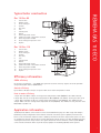
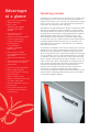
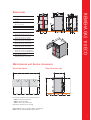
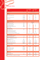
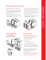
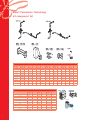
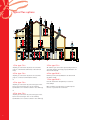
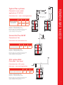
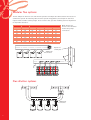
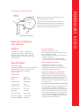
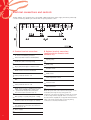
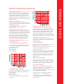
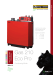
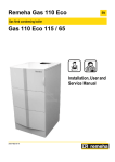
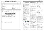
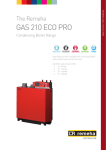
REMEHA GAS 110 ECO
High efficiency floor standing
fully condensing boiler with
ultra low NOx emission
for single and modular/
cascade applications
GAS 110 ECO
CONDENSING
Outputs: Gas 110 Eco
- 65
13.3 - 65 kW
- 115
18.4 - 113.8 kW
Gas
110 Eco
Modular / Cascade
Gas Fired Condensing Boiler
TreadLightly
ON THE PLANET
Introduction
Remeha Gas 110 Eco boilers are floor
standing gas-fired condensing boilers
fitted with an "Open Therm" control
interface which enable
direct weather
compensation using Remeha single
and multi boilers controls or the
customer can choose to use external
control options supplied by others
without affecting boiler performance.
The Remeha Gas 110 Eco has been
developed specifically to fit directly
into the same floor area as a
traditional boiler of equal output.
This will promote the benefit of
higher energy efficiency and lower
carbon emissions. They are designed
for sealed and open vented heating
systems, with a maximum operating
temperature of 90°C. Installation is
recommended where possible on low
temperature heating installations.
Boiler description
The Remeha Gas 110 Eco 115 / 65 are floor standing, condensing
boilers. The one piece, cast aluminium heat exchanger and other
major components are contained within a sealed air box. This forms
the main boiler casing with a removable front section for
maintenance purposes. All electrical and electronic controls are
contained within the boiler casing.
The combined flue gas outlet and combustion air inlet are mounted
on the top of the boiler, with the flow, return, gas and condensate
connections located at the rear of the boiler. The boiler is suitable
for room-sealed or open flue applications. It has been designed for
central heating and indirect hot water production. It must be
installed on a fully pumped system and is suitable for use on both
sealed and open vented installations (minimum operating pressure
of 0.5 bar open vented and 0.8 bar pressurised).
The pre-mix, down-firing gas burner (NG or LPG) with its gas/air
ratio control system, ensures clean, trouble free operation with
higher than average efficiencies (of up to 110% NCV) in the
condensing mode, combined with ultra low NOx and minimum CO
emissions. The standard control package allows actual and set
values to be read and adjusted on the built-in digital display which
also provides normal operating and fault code indication. An
intelligent, advanced boiler control (abc) continuously monitors the
boiler conditions, varying the heat output to suit the system load.
The control is able to react to external “negative” influences in the
rest of the system (flow rates and air/gas supply problems)
maintaining boiler output for as long as possible without resorting
to a lock out condition. At worst the boiler will reduce its output
and/or shut down (shut-off mode); awaiting the “negative”
conditions to return to normal before re-starting. The ‘abc’ control
cannot override the standard flame safety controls.
Declaration of compliance
Contents
2
page
We hereby certify that the series of appliances specified hereinafter
is in compliance with the standard model described in the EC
declaration of compliance, and that it is manufactured and
marketed in compliance with the requirements and standards of the
following European Directives.
Introduction/Boiler description
2
Typical boiler construction
3
Efficiency/Application information
3
Product type:
Gas fired condensing boiler
Advantages at a glance/Operating principle
4
Formats:
Remeha Gas 110 Eco 115 / 65
Dimensions
5
Standards & rules:
Maintenance and Service clearances
5
Technical data
6
- 90/396/EEC Gas Appliance Directive
Reference Standards: EN 437; EN 483;
EN 625; EN 677
Modular/cascade boiler options
7
Smart Connection Technology
8
Typical installations
9
Typical flue options
10
Flue systems
11
Modular flue systems
12
Inspecting
organisation:
Flue dilution systems
12
Values:
Electrical installations and controls
13
Electrical connections and controls
14
Optional controls and accessories
15
Manufacturer:
Broag-Remeha Ltd, Remeha House,
Molly Millars Lane RG41 2QP WOKINGHAM, Berks
- 2006/95/EC Low Voltage Directive
Reference Standard: EN 60.335.1
- 2004/108/EC Electromagnetic Compatibility Directive
Generic standards: EN1000-6-3 ; EN 61000-6-1
- 92/42/EEC Efficiency Directive ****
Gastec
NOx (mg/kWh) dry @ 0% O2
Gas 110 Eco 65 25 21 - DIN 4702 Teil 8
Gas 110 Eco 115 30 31 - EN 297A3
CE-0063BS3826
Gas 110 Eco 65
1.
2.
3.
4.
5.
6.
7.
8.
9.
10.
11.
12.
13.
Fan air inlet
Return sensor
Heat exchanger
Venturi
Gas valve
Fan
Control panel
Burner
Flow temperature sensor
Ignition electrode + Ionisation electrode
Flame inspection window
Heat exchanger inspection cover
Siphon
Gas 110 Eco 115
1.
2.
3.
4.
5.
6.
7.
8.
9.
10.
11.
12.
13.
Fan air inlet
Return sensor
Heat exchanger
Venturi
Gas valve
Fan
Control panel
Burner
Flow temperature sensor
Ignition electrode + Ionisation electrode
Flame inspection window
Heat exchanger inspection cover
Siphon
REMEHA GAS 110 ECO
Typical boiler construction
Efficiency information
SBEM efficiency
65–97.57% 115–96.45% – The SBEM ‘heat generator seasonal efficiency’ figures are based upon GCV
using formula (30% *0.81) + (100%*0.19)
Annual efficiency
Up to 109% at Hi (98% at Hs) at an input of 30% and a return temperature of 30°C.
Heat to water efficiency
a. Up to 99% at Hi (89% at Hs) at an average water temperature of 70°C (80/60ºC) - Gas 110 Eco 65 only.
b. Up to 98% at Hi at an average water temperature of 70°C (80/60ºC) - Gas 110 Eco 115 only, also 88% at Hs.
c. Up to 110% at Hi (99% at Hs) at an average water temperature of 35°C (40/30ºC) - Gas 110 Eco 65 only.
d. Up to 106% at Hi at an average water temperature of 35°C (40/30ºC) - Gas 110 Eco 115 only, also 95% at Hs.
Note: NCV = Hi, GCV = Hs
Application information
The Remeha Gas 110 Eco can be used on all new and refurbishment projects in both single and multiple
(modular/cascade) configurations. Conventional and room-sealed flue system capability means that the
boiler can be sited almost anywhere within a building. The Remeha weather compensators options are able
to communicate directly with the boiler controls (two wire) to make full use of its fully modulating feature,
ensuring that the boiler closely matches the system demand at all times. External control systems (BMS)
can be interfaced with the boiler to provide on/off, high/low or modulating (0-10v) control options.
3
Advantages
at a glance
• High efficiency: 110% NCV at
40/30ºC (99% GCV)
• Boiler control:
a) Modulating (18-100%)
b) High/low (18-100%)
c) On/off
• Conventional or “room
sealed” flue options
• The boiler is particularly suitable
for retro-fit applications,
having a small footprint
• Premix burner for
clean combustion
• Low NOx <35mg/kWh
(02=0%, dry)
• Quiet operation <48 dBA
• Cascade / Modular packages for
up to 6 boilers
• Quick and easy installation
• Advanced boiler control, Remeha’s
‘abc’, for reliable heat delivery
• Digital display
• Data file for storing information
• Remote signalling options
• Cast aluminium heat exchanger
• Easy maintenance
• Built-in calorifier control
• Options for modular control and/
or weather compensator
• Control 0-10V signal or volt free
• PC connection
• For use with natural gas and
L.P.G. (Some models require a
conversion kit)
4
Operating principle
Combustion air is drawn into the closed air box, by a variable speed
fan, through the air inlet connection from the plant room (open
flued) or from outside via the concentric flue system (room-sealed).
On the inlet side of the fan is a specially designed venturi which is
connected to the outlet side of the gas valve.
Depending on the demand (under the dictates of flow/return sensor
and other external/internal control inputs) the electronic control
unit directly monitors the volume of gas and air being delivered to
the premix burner. This mixture is initially ignited by the combined
ignition/ionisation probe which then monitors the state of the
flame. Should the flame not ignite or be unstable, within the preset safety time cycle, the controls will shut the boiler down (after 5
attempts) requiring manual intervention to reset the boiler. The
digital display will also indicate a flashing fault code confirming
the reason for the failure.
The products of combustion in the form of hot flue gases are forced
through the heat exchanger, transferring their heat to the system
water (the flue gas temperature is reduced to approximately 5°C
above the temperature of the system return water) then discharged
via the condensate collector, vertically through the flue connection
to atmosphere. Because of the low flue gas exit temperature there
will be a vapour cloud formed at the flue gas terminal – this is not
smoke, simply water vapour formed during the combustion process.
If the controls allow the flow and therefore return temperature to
fall below dew point (55°C) this water vapour will begin to
condense out in the boiler transferring it’s latent heat into the
system water, increasing the output of the boiler without
increasing gas consumption. Condensation formed within the boiler
and flue system is discharged from the boiler to an external drain
via the drain pan/siphon supplied.
1
2
3
4
5
REMEHA GAS 110 ECO
Dimensions
Heating outlet
R 1 1/4
Heating return
R 1 1/4
Condensates discharge
(Ø 25 mm external)
Automatic air vent
Gas inlet R 3/4
A
Remeha Gas 110 Eco 65: 1100 mm
Remeha Gas 110 Eco 115: 1322 mm
B Remeha Gas 110 Eco 65: 410 mm
Remeha Gas 110 Eco 115: 632 mm
C Remeha Gas 110 Eco 65: 124 mm
Remeha Gas 110 Eco 115: 346 mm
D Remeha Gas 110 Eco 65: 968 mm
Remeha Gas 110 Eco 115: 1190 mm
E Remeha Gas 110 Eco 65: 152 mm
Remeha Gas 110 Eco 115: 374 mm
ØF Forced flue connection
Remeha Gas 110 Eco 65: Ø 100/150 mm
Remeha Gas 110 Eco 115: Ø 100/150 mm
R Thread
(1) Basic dimension 21 mm
adjustment possible: 21 to 40 mm
Maintenance and Service clearances
View from above
View from the side
Clear space should be left around the boiler :
- 700mm in front of the boiler
- 400mm above the boiler
- 100mm each side of the boiler
(Facilitates removal of the casing)
Note: 300mm refers to singular boiler installations,
600mm refers to modular boiler applications.
5
Technical data
Boiler type
CE identification no
Remeha
Gas 110 Eco
65
Remeha
Gas 110 Eco
115
****
CE-0063BS3826
min. kW
max. kW
min. kW
max. kW
min. kW
max. kW
Modulating, 0 - 10V or on/off
12
16.6
61
107
13.3
18.4
65
113.8
12.2
17.2
62
111
General
Input control
Nominal output (80/60 °C) pn
Nominal output (50/30 °C) pn
Nominal input
Gas and flue gas side
Category
Inlet gas pressure natural gas
Inlet gas pressure propane
Gas consumption natural Gas
Gas consumption propane
NOx emission (dry 0% O2) EN297 A3
NOx classification
Residual fan pressure
Mass flue Gas flow rate
Mass flue Gas flow rate
CO2 content in flue gases natural gas
CO2 content in flue gases propane
Average flue gas temperature (75/60 ºC)
Type classification with respect to flue gas discharge
mbar
mbar
M3/h
Kg/h
mg/kWh
min
max
ºC
II2h3p / I2h
17/30
37/50
6.6
11.7
4.8
N/A
32
35
5
5
100
250
21
29
104
178
9
9
10.7
N/A
65
67.9
B23 C13 C33 C43 C53 C63 C83
Central heating side
High limit temperature (adjustable)
Operating temperature range
Minimum working pressure sealed system
Minimum working pressure open vented
Maximum working pressure
Water content
Hydraulic resistance at Δt = 20 ºC
Hydraulic resistance at Δt = 11 ºC
Nominal water flow rate Δt = 20 ºC
Nominal water flow rate Δt = 11 ºC
Condensation water pH
ºC
ºC
bar
bar
bar
litres
mbar(kpa)
mbar(kpa)
M3/h(l/s)
M3/h(l/s)
110
90
0.8
0.5
4
6.5
175 (17.5)
580 (58)
2.62(0.73)
4.76(1.32)
3 -5
110
90
0.8
0.5
4
7.5
230 (23)
830 (83)
4.6(1.28)
8.36(2.32)
3-5
V/Ph/Hz
min Watt
max Watt
max Watt
IP
230/1/50
30
85
190
21
230/1/50
40
240
190
21
ºC
RAL
116
0-40
White/2002 Red
133
0-40
White/2002 Red
< 48
< 52.5
Electrical
Main voltage
Input power (without pump)
Input power (without pump)
Input power (pump only)
Insulation class
Other
Shipping weight
Environment temperature
Colour of casing
Noise level at a distance of 1M from the boiler dB(A)
6
Smart Connection Technology
Broags new ‘Smart Connection Technology’ modular
pipe work kit has been designed to reduce installation
time and simplify the planning of the primary circuit
layout, for up to 6 boilers.
The pipe work kit comprises of a flow & return
assembly to each boiler which incorporates a suitably
sized circulation pump, safety relief valve set at 3 Bar
and isolation valves.
Smart Connection
Technology kit
assembly detail
Each manifold (one per boiler) simply bolts together at
700mm centres, with a low loss header and connecting
/ blanking flanges completing the installation.
The standard manifold provides connections for both
in-line and back to back boiler configurations, simply
blank off the connections not used with the caps
contained within the kit.
The pipe work kits have been designed to operate at a
15 ºC ΔT with the primary pump set on speed 2 on the
65 model and speed 3 on the 115 model.
REMEHA GAS 110 ECO
Modular/cascade boiler options
Further options
The following options can be
specified at time of order:
- 0-10v control interface
(Temperature or output)
- Flue gas damper
- Facility to fit outside sensor
- Rematic 2945 CK3 controller
- Rematic MC4 controller (4 boilers max)
- Celcia 20 controller single or multiple boilers
(multiple boilers in conjunction with MC4)
Note 1: When connecting the interlocks or
communication wires of more than one boiler
in parallel observe and match the
connection polarity.
Note 2: Unless otherwise stated at the time of
ordering, the boiler will be delivered with the
standard control fitted. Additional options will be
supplied for on-site fitting by others.
7
Smart Connection Technology
kit component list
Smart Connection Technology kit - component list
In line
kit option
Pipework
kit
Qty
Pump
Qty
Header
Qty
Counter
flanges
Qty
Blank
flanges
Qty
Blanking
caps
Qty
LL header
Qty
2 x 65
100011490
2
S10004
2
100011703
2
112632
1
111701
1
111708
2
114658
1
3 x 65
100011490
3
S10004
3
100011703
3
112632
1
111701
1
111708
3
114658
1
4 x 65
100011490
4
S10004
4
100011703
4
112632
1
111701
1
111708
4
114658
1
5 x 65
100011490
5
S10004
5
100011703
5
112632
1
111701
1
111708
5
114658
1
6 x 65
100011490
6
S10004
6
100011703
6
112632
1
111701
1
111708
6
114658
1
2 x 115
100011491
2
S10004
2
100011703
2
112632
1
111701
1
111708
2
114658
1
3 x 115
100011491
3
S10004
3
100011703
3
112632
1
111701
1
111708
3
114658
1
4 x 115
100011491
4
S10004
4
100011703
4
112632
1
111701
1
111708
4
114658
1
5 x 115
100011491
5
S10004
5
100011492
5
112633
1
111703
1
111708
5
114661
1
6 x 115
100011491
6
S10004
6
100011492
6
112633
1
111703
1
111708
6
114661
1
Smart Connection Technology kit - optional parts list
8
In line kit option
LLH
insulation
Qty
Header
bends
Qty
Flue
damper
Qty
2 x 65
111067
1
111788
1
100002685
2
3 x 65
111067
1
111788
1
100002685
3
4 x 65
111067
1
111788
1
100002685
4
5 x 65
111067
1
111788
1
100002685
5
6 x 65
111067
1
111788
1
100002685
6
2 x 115
111067
1
111788
1
100002685
2
3 x 115
111067
1
111788
1
100002685
3
4 x 115
111067
1
111788
1
100002685
4
5 x 115
111067
1
111790
1
100002685
5
6 x 115
111067
1
111790
1
100002685
6
100002685
Single boiler
Single boiler, DHW priority
with low loss header
REMEHA GAS 110 ECO
Typical installations
Modular/cascade
boiler configuration
Note 1: These layouts do not constitute a design. Calculations must be
carried out to ensure pipework and pumps are sized to match boiler
nominal flows against system design flow requirements.
Note 2: All connections are to the back of the boiler
9
Typical flue options
1 Flue type C13 :
5 Flue type C53 :
Air/flue gas connection by means of concentric
pipes to a horizontal terminal (so-called forced
flue)
Air and flue gas connection separated by means of
a bi-flow adapter and single pipes (combustive air
taken from outside)
2 Flue type C33 :
6 Flue type B23P :
Air/flue gas connection by means of concentric
pipes to a vertical terminal (roof outlet)
Chimney connection (combustive air taken from
the boiler room)
or
7 Flue type B23P :
3 Flue type C33 :
Cascade installation Compulsory accessories:
Flue damper
Air/flue gas connection by concentric pipes in the
boiler room and single pipes in the chimney
(combustive air in counter current in the chimney)
or
4 Flue type C33 :
Air/flue gas connection by concentric pipes in the
boiler room and single "flex" in the chimney
(combustive air in counter current in the chimney)
10
Note: If further classification is required please
refer to a specialist flue contractor
Concentric room-sealed
applications (C13/C33)
Calculation data - room sealed applications
Flue
option
Gas 110
65
Gas 110
115
C13
9M
5.9 M
C33
11.5 M
9.4 M
Maximum Length O/L
Using 100/150mm
Concentric Flue
90° Elbow = An equivalent length of 1.9 M
45° Elbow = An equivalent length of 1.2 M
Inspection Tee = An equivalent length of 3.3 M
Note: Flue Lengths can be extended by using larger diameter
flue pipe. For further clarification please consult a flue
specialist and Broag Technical Department.
C13
Convential flue B23P
Conventional flue
C33
REMEHA GAS 110 ECO
Typical flue systems
Calculation data conventional flue
Maximum Length O/L
Using 100 Single Wall Flue
Flue
option
Gas 110
65
Gas 110
115
B23P
27 M
19 M
90° Elbow = An equivalent length of 4.9 M
45° Elbow = An equivalent length of 1.4 M
Inspection Tee = An equivalent length of 5.3 M
Note: Flue Lengths can be extended by using larger diameter
flue pipe. For further clarification please consult a flue
specialist and Broag Technical Department.
CLV system B53
(Twin pipe - two zone)
Calculation data –CLV system
(twin pipe – two zone) applications
Maximum Length O/L
Using 2 No 100mm Single Wall Flues
Flue
option
Gas 110
65
Gas 110
115
C53
23 M
(11 M Air / 5
M Gas)
16 M
90° Elbow = An equivalent length of 5 M
45° Elbow = An equivalent length of 1.2 M
Inspection Tee = An equivalent length of 5.3M
Note: Flue Lengths can be extended by using larger diameter
flue pipe. For further clarification please consult a flue
specialist and Broag Technical Department.
11
Modular flue systems
The flue damper kit allows for safe and efficient operation of multiple Gas 110 Eco boilers when used on a
common flue system. The following table offers flue system sizing guidance, based upon the total heat
output and the available chimney height. Please consult a flue specialist and Broag technical department
for any further assistance.
Heat output P
Boiler types
kW
122
183
244
305
366
214
321
428
535
642
2x65
3x65
4x65
5x65
6x65
2x115
3x115
4x115
5x115
6x115
Note: Connect the
boilers to the horizontal
header using swept
connections.
Ød-ØD(mm)
H-2-5m
H-5-9m
H-9-13m
H-13-17m
155
220
265
305
340
200
285
345
395
440
145
200
240
275
300
185
255
305
345
385
145
195
230
255
280
180
240
285
323
355
145
190
225
250
275
180
235
275
315
345
Tapered cone
c/w bird guard
100mm boiler
connections
Flue dilution systems
100mm boiler
connections
12
Flue dilution systems continued
Opening in
duct 2 x D
Note: Please contact a flue specialist for assistance
with Flue dilution system design.
* Typical modular flue dilution system showing the
flue break necessary for use on all pre-mix boilers, to
the flue break prevents the dilution fan effecting the
gas/air ratio control system within the boiler.
Drain
Typical duct entry detail
Electrical installation
and controls
General
Fuse specification
The Remeha Gas 110 Eco is supplied as
standard with electronic control and flame
ionisation safety controls, with a specially
designed microprocessor at the heart of the
control system.
The boiler is protected by fuses:
On the 203v power supply located in the control
panel 6.3amps (fast acting).
On the control box located on the bottom right
hand side of the boiler.
- control circuit 230v 2 amps (fast acting).
- control circuit 24v d.c. 4 amps (slow acting).
Specifications
Boiler temperature control
Electrical supply
The Remeha Gas 110 Eco has electronic
temperature control with flow and return
temperature sensors. The flow temperature can
be adjusted between 20 and 90°C.
The Remeha Gas 110 Eco must have a permanent
230V-50Hz single phase supply rated at 6.3
amps. The control unit is not phase/
neutral sensitive.
High limit temperature protection
Manufacture:
Gasmodul
Model:
MCBA 1461 D
Supply voltage:
230 V/50 Hz
The high limit, temperature protection device
switches off and locks out the boiler when the
flow temperature exceeds the high limit set point
(adjustable). When the fault is corrected the
boiler can be restarted by using the reset key on
the control panel.
Electrical rating:
10 VA
Low water protection (flow and content)
Pre-purge time:
0.3 seconds
Post-purge time:
10 seconds
Safety time:
3 seconds
Anti-hunting time:
150 seconds
Pump run on (HTG):
1 -15 minutes
Pump run on (DHW):
5 minutes
The Remeha Gas 110 Eco are supplied with a low
water protection on the basis of temperature
measurement. By modulating back at the moment
that the water flow threatens to fall too low, the
boiler is kept operating for as long as possible. In
the event of low flow (F/R st > 45°C) the boiler
will shut off and not lockout. If the boiler is fired
dry it will go to lockout (code 18).
Control box
REMEHA GAS 110 ECO
Bellmouth
2 x D + 50
13
Electrical connections and controls
The Gas 110 Eco 115 / 65 must have a fixed 230V - 50Hz single phase mains supply. It must be powered by
a circuit containing a double pole switch with an opening distance 3 mm.
A. Standard terminal connections
1
0 - 10 V or modulating controller
when used with interface S55443 (VFC)
2
3
15
System pump
Enable On / Off or 1st stage firing
16
17
High / low (2nd stage) or outdoor sensor
18
20
DHW sensor or volt free thermostat
21
22
4
5
DHW pump
6
7
Outdoor sensor
8
9
10 Safety interlock link 10 – 14
11
12
N.A.
13
14
Safety interlock link 14 – 10
15
16
DHW diverting valve or DHW primary pump,
17 240 V signal to BMS (power supply live)
- optional Flue damper kit connections
18 use 18 for neutral and link 16 to 23.
19
Boiler pump or system pump (max. 1 Amp)
20
21
Common alarm volt free (opens on failure)
22
23 Boiler run volt free (closes on run) optional
Flue damper kit connections use 24 for live
24 and link 23 to 16.
25
26 Power supply
27
F3 6.3 A fuse
14
B. Optional terminal connections
(supplied with the Rematic 2945
controller kit)
DHW sensor
23
24
Flow temperature sensor
25
34
Internal sensor
35
36
Extension timer
37
Note: The power and control terminal wiring strip can be
accessed by removing the top casing panel and
instrument cover plate. All external connections are made
on the 27 way terminal strip (A). There is a facility for a
second terminal strip (B), this is supplied with the Rematic
2945 controller kit and provides all necessary wiring
connections to interface with the boiler.
a) Rematic 2945 3C K - Part KT196/110 to KT201/110
This controller provides optimum start, single zone
weather compensation and priority DHW (if required).
Fit the controller in the boiler. Connection takes place
using the supplied rematic adapter plate and the
supplied interface that can be integrated in the control
panel. Refer to the relevant controller documentation for
detailed information.
b) Celcia 20 controller - Part 58222
This controller provides Optimiser/compensator for use
on single or multiple boilers (comminicates according to
the OpenTherm protocol).
c) Modulating cascade controller
rematic MC4 - Part KT821 to KT824
The rematic MC4 modular / cascade control unit is
supplied with the Celcia 20 controller and is suitable for
the modulated control of 2 to 4 Remeha Gas 110 ECO
units in modular/cascade in conjunction with the Celcia
20 controller. This controller is wall-mounted and
communicates according to the OpenTherm protocol.
Several rematic MC controllers can be combined to
control more than 4 boilers. Refer to the relevant
controller documentation for detailed information.
d) Analogue control (0-10v) - Part S55443
Two formats available :
1. Temperature based (10 to 90°C)
Set the minimum and maximum temperatures required
on the basis of the voltage supplied by an external
analog signal (0-10V DC).
0 volt = boiler off
0.5 volt = boiler on
1 volt = boiler 10°C
5 volts = 50°C etc.
e) Optional flue damper - Part S00002685
The flue damper kit is for use on all modular and
common flue systems, it should be fitted in the vertical
position between the boiler and the header tee. A slip
coupling should be accommodated to allow for future
access and servicing. Supplied within the kit is a link
wire, which links terminals 16 & 23 on the Standard
terminal strip - A (page 14). Live is supplied via terminal
24 and neutral via terminal 18, earth bonding is required.
f) Optional outside sensor - Part S62372
REMEHA GAS 110 ECO
Optional controls and accessories
The sensor can be fitted to boiler controls to give simple
outside weather compensation or in conjunction with
the Celcia controller.
3. Frost protection
Install the boiler in a frost-free room. The built-in frost
protection system is activated as follows :
Below 7°C the system pump will be switched on if it is
connected to the boiler. Pump terminals on
boiler terminals 19 & 20.
Below 3°C the boiler will be switched on, but is limited
to a flow temperature of 10°C, when both will switch off.
Note: This control function is designed to protect the
boiler only, for full frost protection of the system and
building, a frost thermostat or weather compensator
should be used.
Boiler or system pump
A system pump can be connected to the boiler (230-150 supply max. current rating of 1 amp). If the system
pump requires more than 1 amp the terminals can only
be used to provide a switch signal to a pump relay.
System water quality
2. Output based (18-100%)
Set the minimum and maximum outputs required on the
basis of the voltage supplied by an external analog
signal (0-10V DC).
0 volt = boiler off
0.5 volt = boiler on 10%
1-10 volt = boiler modulates between 10 and 100%
on demand.
Before operation the system should be thoroughly
flushed and re-filled with mains cold water. As the heat
exchanger is aluminium, if water treatment is
considered, a minimum pH level of 7 and a maximum pH
level of 9 MUST NOT BE EXCEEDED.
The water treatments recommended by Broag are :
- Fernox "Copal ®"
- Sentinal "X-100 ®"
- In addition to strainers we recommend the use of a
low loss header to further protect the boiler from
system impurities.
15
TreadLightly
GAS 110 ECO
CONDENSING
Broag Ltd. Head Office
Remeha House
Molly Millars Lane
Wokingham
Berkshire RG41 2QP
T: 0118 978 3434
F: 0118 978 6977
E: [email protected]
www.uk.remeha.com
The data published in this technical sales leaflet is based on the latest information (at date of
publication) and may be subject to revisions. It should be read in conjunction with our full technical
brochure (available on request). We reserve the right to continuous development in both design and
manufacture, therefore any changes to the technology employed may not be retrospective, nor may we
be obliged to adjust earlier supplies accordingly.
Issue 1 date: 01/05/08
Broag UK is committed to carbon offsetting
Designed and produced by Sans Frontiere Marketing Communications – 01273 487 800 – www.sansfrontiere.co.uk
ON THE PLANET