1
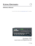
System 7SC
System Switcher
68-499-01
Printed in the USA
Precautions
Safety Instructions • English
This symbol is intended to alert the user of important operating and maintenance
(servicing) instructions in the literature provided with the equipment.
This symbol is intended to alert the user of the presence of uninsulated dangerous
voltage within the product's enclosure that may present a risk of electric shock.
Warning
Power sources • This equipment should be operated only from the power source indicated on the
product. This equipment is intended to be used with a main power system with a grounded
(neutral) conductor. The third (grounding) pin is a safety feature, do not attempt to bypass or
disable it.
Caution
Power disconnection • To remove power from the equipment safely, remove all power cords from
the rear of the equipment, or the desktop power module (if detachable), or from the power
source receptacle (wall plug).
Read Instructions • Read and understand all safety and operating instructions before using the
equipment.
Power cord protection • Power cords should be routed so that they are not likely to be stepped on or
pinched by items placed upon or against them.
Retain Instructions • The safety instructions should be kept for future reference.
Servicing • Refer all servicing to qualified service personnel. There are no user-serviceable parts
inside. To prevent the risk of shock, do not attempt to service this equipment yourself because
opening or removing covers may expose you to dangerous voltage or other hazards.
Follow Warnings • Follow all warnings and instructions marked on the equipment or in the user
information.
Avoid Attachments • Do not use tools or attachments that are not recommended by the equipment
manufacturer because they may be hazardous.
Slots and openings • If the equipment has slots or holes in the enclosure, these are provided to
prevent overheating of sensitive components inside. These openings must never be blocked by
other objects.
Lithium battery • There is a danger of explosion if battery is incorrectly replaced. Replace it only
with the same or equivalent type recommended by the manufacturer. Dispose of used batteries
according to the manufacturer's instructions.
Consignes de Sécurité • Français
Avertissement
Ce symbole sert à avertir l’utilisateur que la documentation fournie avec le matériel
contient des instructions importantes concernant l’exploitation et la maintenance
(réparation).
Alimentations• Ne faire fonctionner ce matériel qu’avec la source d’alimentation indiquée sur
l’appareil. Ce matériel doit être utilisé avec une alimentation principale comportant un fil de
terre (neutre). Le troisième contact (de mise à la terre) constitue un dispositif de sécurité :
n’essayez pas de la contourner ni de la désactiver.
Ce symbole sert à avertir l’utilisateur de la présence dans le boîtier de l’appareil de
tensions dangereuses non isolées posant des risques d’électrocution.
Déconnexion de l’alimentation• Pour mettre le matériel hors tension sans danger, déconnectez tous
les cordons d’alimentation de l’arrière de l’appareil ou du module d’alimentation de bureau (s’il
est amovible) ou encore de la prise secteur.
Attention
Lire les instructions• Prendre connaissance de toutes les consignes de sécurité et d’exploitation avant
d’utiliser le matériel.
Conserver les instructions• Ranger les consignes de sécurité afin de pouvoir les consulter à l’avenir.
Respecter les avertissements • Observer tous les avertissements et consignes marqués sur le matériel ou
présentés dans la documentation utilisateur.
Eviter les pièces de fixation • Ne pas utiliser de pièces de fixation ni d’outils non recommandés par le
fabricant du matériel car cela risquerait de poser certains dangers.
Protection du cordon d’alimentation • Acheminer les cordons d’alimentation de manière à ce que
personne ne risque de marcher dessus et à ce qu’ils ne soient pas écrasés ou pincés par des
objets.
Réparation-maintenance • Faire exécuter toutes les interventions de réparation-maintenance par un
technicien qualifié. Aucun des éléments internes ne peut être réparé par l’utilisateur. Afin
d’éviter tout danger d’électrocution, l’utilisateur ne doit pas essayer de procéder lui-même à ces
opérations car l’ouverture ou le retrait des couvercles risquent de l’exposer à de hautes tensions
et autres dangers.
Fentes et orifices • Si le boîtier de l’appareil comporte des fentes ou des orifices, ceux-ci servent à
empêcher les composants internes sensibles de surchauffer. Ces ouvertures ne doivent jamais
être bloquées par des objets.
Lithium Batterie • Il a danger d'explosion s'll y a remplacment incorrect de la batterie. Remplacer
uniquement avec une batterie du meme type ou d'un ype equivalent recommande par le
constructeur. Mettre au reut les batteries usagees conformement aux instructions du fabricant.
Sicherheitsanleitungen • Deutsch
Vorsicht
Dieses Symbol soll dem Benutzer in der im Lieferumfang enthaltenen
Dokumentation besonders wichtige Hinweise zur Bedienung und Wartung
(Instandhaltung) geben.
Stromquellen • Dieses Gerät sollte nur über die auf dem Produkt angegebene Stromquelle betrieben
werden. Dieses Gerät wurde für eine Verwendung mit einer Hauptstromleitung mit einem
geerdeten (neutralen) Leiter konzipiert. Der dritte Kontakt ist für einen Erdanschluß, und stellt
eine Sicherheitsfunktion dar. Diese sollte nicht umgangen oder außer Betrieb gesetzt werden.
Dieses Symbol soll den Benutzer darauf aufmerksam machen, daß im Inneren des
Gehäuses dieses Produktes gefährliche Spannungen, die nicht isoliert sind und
die einen elektrischen Schock verursachen können, herrschen.
Stromunterbrechung • Um das Gerät auf sichere Weise vom Netz zu trennen, sollten Sie alle
Netzkabel aus der Rückseite des Gerätes, aus der externen Stomversorgung (falls dies möglich
ist) oder aus der Wandsteckdose ziehen.
Achtung
Lesen der Anleitungen • Bevor Sie das Gerät zum ersten Mal verwenden, sollten Sie alle Sicherheits-und
Bedienungsanleitungen genau durchlesen und verstehen.
Aufbewahren der Anleitungen • Die Hinweise zur elektrischen Sicherheit des Produktes sollten Sie
aufbewahren, damit Sie im Bedarfsfall darauf zurückgreifen können.
Befolgen der Warnhinweise • Befolgen Sie alle Warnhinweise und Anleitungen auf dem Gerät oder in
der Benutzerdokumentation.
Keine Zusatzgeräte • Verwenden Sie keine Werkzeuge oder Zusatzgeräte, die nicht ausdrücklich vom
Hersteller empfohlen wurden, da diese eine Gefahrenquelle darstellen können.
Instrucciones de seguridad • Español
Schutz des Netzkabels • Netzkabel sollten stets so verlegt werden, daß sie nicht im Weg liegen und
niemand darauf treten kann oder Objekte darauf- oder unmittelbar dagegengestellt werden
können.
Wartung • Alle Wartungsmaßnahmen sollten nur von qualifiziertem Servicepersonal durchgeführt
werden. Die internen Komponenten des Gerätes sind wartungsfrei. Zur Vermeidung eines
elektrischen Schocks versuchen Sie in keinem Fall, dieses Gerät selbst öffnen, da beim Entfernen
der Abdeckungen die Gefahr eines elektrischen Schlags und/oder andere Gefahren bestehen.
Schlitze und Öffnungen • Wenn das Gerät Schlitze oder Löcher im Gehäuse aufweist, dienen diese
zur Vermeidung einer Überhitzung der empfindlichen Teile im Inneren. Diese Öffnungen dürfen
niemals von anderen Objekten blockiert werden.
Litium-Batterie • Explosionsgefahr, falls die Batterie nicht richtig ersetzt wird. Ersetzen Sie
verbrauchte Batterien nur durch den gleichen oder einen vergleichbaren Batterietyp, der auch
vom Hersteller empfohlen wird. Entsorgen Sie verbrauchte Batterien bitte gemäß den
Herstelleranweisungen.
Advertencia
Este símbolo se utiliza para advertir al usuario sobre instrucciones importantes de
operación y mantenimiento (o cambio de partes) que se desean destacar en el
contenido de la documentación suministrada con los equipos.
Alimentación eléctrica • Este equipo debe conectarse únicamente a la fuente/tipo de alimentación
eléctrica indicada en el mismo. La alimentación eléctrica de este equipo debe provenir de un
sistema de distribución general con conductor neutro a tierra. La tercera pata (puesta a tierra) es
una medida de seguridad, no puentearia ni eliminaria.
Este símbolo se utiliza para advertir al usuario sobre la presencia de elementos con
voltaje peligroso sin protección aislante, que puedan encontrarse dentro de la caja
o alojamiento del producto, y que puedan representar riesgo de electrocución.
Desconexión de alimentación eléctrica • Para desconectar con seguridad la acometida de
alimentación eléctrica al equipo, desenchufar todos los cables de alimentación en el panel trasero
del equipo, o desenchufar el módulo de alimentación (si fuera independiente), o desenchufar el
cable del receptáculo de la pared.
Precaucion
Leer las instrucciones • Leer y analizar todas las instrucciones de operación y seguridad, antes de usar
el equipo.
Conservar las instrucciones • Conservar las instrucciones de seguridad para futura consulta.
Obedecer las advertencias • Todas las advertencias e instrucciones marcadas en el equipo o en la
documentación del usuario, deben ser obedecidas.
Evitar el uso de accesorios • No usar herramientas o accesorios que no sean especificamente
recomendados por el fabricante, ya que podrian implicar riesgos.
Protección del cables de alimentación • Los cables de alimentación eléctrica se deben instalar en
lugares donde no sean pisados ni apretados por objetos que se puedan apoyar sobre ellos.
Reparaciones/mantenimiento • Solicitar siempre los servicios técnicos de personal calificado. En el
interior no hay partes a las que el usuario deba acceder. Para evitar riesgo de electrocución, no
intentar personalmente la reparación/mantenimiento de este equipo, ya que al abrir o extraer las
tapas puede quedar expuesto a voltajes peligrosos u otros riesgos.
Ranuras y aberturas • Si el equipo posee ranuras o orificios en su caja/alojamiento, es para evitar el
sobrecalientamiento de componentes internos sensibles. Estas aberturas nunca se deben obstruir
con otros objetos.
Batería de litio • Existe riesgo de explosión si esta batería se coloca en la posición incorrecta. Cambiar
esta batería únicamente con el mismo tipo (o su equivalente) recomendado por el fabricante.
Desachar las baterías usadas siguiendo las instrucciones del fabricante.
Table of Contents
Chapter 1 • Introduction ....................................................................................................... 1-1
About this Manual ............................................................................................................. 1-2
About the System 7SC ...................................................................................................... 1-2
What is the System 7SC? .................................................................................................... 1-2
Controlling the switcher and an A/V system .................................................................... 1-2
Features and Options ........................................................................................................ 1-4
Features .............................................................................................................................. 1-4
Options and accessories ..................................................................................................... 1-5
Chapter 2 • Installation .......................................................................................................... 2-1
Mounting the Switcher .................................................................................................... 2-2
Tabletop use ....................................................................................................................... 2-2
Rack mounting ................................................................................................................... 2-2
Cabling and Panel Views ................................................................................................. 2-2
Power, video, and audio connections ............................................................................... 2-4
Front panel inputs ............................................................................................................... 2-4
Rear panel inputs ................................................................................................................ 2-5
Outputs ................................................................................................................................ 2-6
Control device connections ............................................................................................... 2-8
Connecting and Slaving a Switcher ......................................................................... 2-12
Labeling Buttons on the System 7SC and SCPs ................................................. 2-14
Button-Label Generator software ................................................................................... 2-14
Installing the software ...................................................................................................... 2-14
Using the software ............................................................................................................ 2-14
Installing labels in the System 7SC’s buttons .................................................................. 2-16
Chapter 3 • Operation and Configuration ................................................................. 3-1
Front Panel Features and Basic Operation ............................................................. 3-2
Control features ................................................................................................................. 3-2
Adjustment features .......................................................................................................... 3-4
Input selection features ..................................................................................................... 3-5
Miscellaneous features ...................................................................................................... 3-5
IR and RS-232 Projector Control .................................................................................. 3-6
Projector control memory ................................................................................................. 3-6
Optimizing the System .................................................................................................... 3-7
Setting up a DVD source ................................................................................................... 3-7
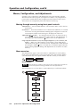
Menus, Configuration, and Adjustments ............................................................... 3-8
Moving through menus by using front panel controls ................................................... 3-8
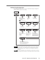
Menu overview .................................................................................................................. 3-8
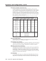
Switcher Setup/Configuration ........................................................................................... 3-9
Scaler Rate (resolution and refresh rate) ......................................................................... 3-10
Scaler Sync (RGB format) .................................................................................................. 3-10
Scaler Polarity (sync polarity) ........................................................................................... 3-10
System 7SC • Table of Contents
i
Table of Contents, cont’d
RGB Delay (Triple-Action Switching™) .............................................................................. 3-10
Scaler Blue Out .................................................................................................................. 3-10
Edge Smoothing ................................................................................................................ 3-11
Add Slave (slaving switchers) ........................................................................................... 3-11
Autoselect #7 (front panel input automatic signal type selection) ............................... 3-11
Audio/Video Adjustments ............................................................................................... 3-12
Input Config(uration) (signal format) .............................................................................. 3-12
Audio Level ........................................................................................................................ 3-12
Blank Input (blanking adjustment) .................................................................................. 3-13
Image Size ......................................................................................................................... 3-13
Size Input ........................................................................................................................... 3-13
IR Learning Configuration ............................................................................................... 3-14
Clearing IR commands from memories ............................................................................ 3-15
Initiating IR learning ......................................................................................................... 3-16
Information System/Options ........................................................................................... 3-17
Reset to Default (clearing settings and adjustments) ..................................................... 3-17
Global system reset ........................................................................................................... 3-17
Image adjustments .......................................................................................................... 3-17
Color, tint, brightness, contrast, detail ............................................................................ 3-17
Centering ........................................................................................................................... 3-18
Executive mode ................................................................................................................ 3-18
Remote Control of the System 7SC ......................................................................... 3-19
SCP control pads .............................................................................................................. 3-19
IR 701 infrared remote control ....................................................................................... 3-20
Selecting an input ............................................................................................................. 3-20
Chapter 4 • Serial Communication ................................................................................. 4-1
RS-232 Programmer’s Guide .......................................................................................... 4-2
Host-to-switcher communications .................................................................................... 4-2
Switcher-initiated messages ............................................................................................... 4-2
Error responses .................................................................................................................... 4-2
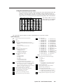
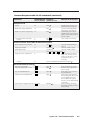
Using the command/response tables ................................................................................. 4-3
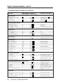
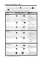
Command/response table for SIS commands .................................................................... 4-4
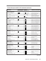
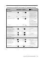
Command/response table for special function SIS commands ......................................... 4-8
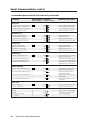
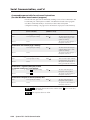
Command/response table for advanced instructions ............................................................
(for the Windows-based control program) ..................................................................... 4-10
Control Software for Windows .................................................................................. 4-11
Installing the software .................................................................................................... 4-11
Using the control program .............................................................................................. 4-11
Mini Mode ......................................................................................................................... 4-11
User Mode ......................................................................................................................... 4-12
I/O Configurations ............................................................................................................. 4-12
Real Time Adjustments ..................................................................................................... 4-13
Projector Driver ................................................................................................................. 4-14
Room & Misc. Options ...................................................................................................... 4-15
Saving and restoring configurations ............................................................................... 4-15
Using the help program ................................................................................................... 4-16
Downloading and using projector drivers ....................................................................... 4-16
Key to file names .............................................................................................................. 4-16
ii
System 7SC • Table of Contents
Appendix A • Appendix ........................................................................................................ A-1
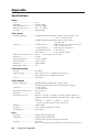
Specifications ....................................................................................................................... A-2
Part Numbers and Accessories .................................................................................... A-5
Included parts ................................................................................................................... A-5
Accessories ......................................................................................................................... A-5
Firmware Upgrade Installation ................................................................................... A-6
Glossary .................................................................................................................................. A-8
68-499-01 Rev. C
Printed in the USA
03 02
All trademarks mentioned in this manual are the properties of their respective owners.
System 7SC • Table of Contents
iii
Table of Contents, cont’d
iv
System 7SC • Table of Contents
System 7SC
1
Chapter One
Introduction
About this Manual
About the System 7SC
Features and Options
Introduction
About this Manual
This manual discusses how to install, operate and configure Extron’s System 7SC
switcher and how to operate the IR 701 infrared remote control that is included
with the System 7SC. For information on installing and operating related
accessories, see the user’s guides for the following products: Extron’s Power Sensor
(part #68-391-01), IR Broadcaster (part #68-392-02); and the SCP/AAP A, SCP 200,
and SCP 250 control pads (part #68-511-01).
Throughout this manual the terms “System 7” and “System 7SC” are used
interchangeably to refer to the same product.
About the System 7SC
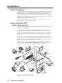
What is the System 7SC?
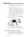
The System 7SC is a seven input, configurable switcher with a built-in video scaler
and projector control ability.
The System 7SC provides central control and integration for small audio/video
(A/V) installations. It offers video and audio switching, room controls, and
projector control. Each of these functions can be controlled at the front panel, by a
hardwired control pad, by infrared remote control (the IR 701), or via RS-232
control.
The switcher can control video and audio input settings; display functions such as
power, video mute and video modes; and room functions, such as lowering or
raising display screens or powering lights on or off. The System 7SC also has the
ability to “learn” infrared projector control commands.
The System 7SC accepts computer-video (RGB), component video, S-video and
composite video, and each input is separately configurable. The switcher also
accepts seven line-level, balanced or unbalanced stereo audio inputs.
Video
Camera
Stereo Audio
Plasma Display
To Input 7
Front Panel
Laptop w/Audio
RS-232 Control
V
S
PUT
OUT H
B
Projector
Control
G
R
6
H/C
HV
R
R-Y
5
RGB
er
Disp
Pow
ol
ntr
Co lay
ns
lay
e
DispMut
ctio
Fun
e
Mut
io
Aud e
Mod
1
Volu
ut
2
me
Inp
5
n
ctio 3
Sele
6
9
4
7
0
m
Roo
G/Y
VID
B
B-Y
1
B
B-Y
AY
AY
REL
E
A
B
C
D
E
H
I J
RS-
232
2
3
4
5
6
7
12V
L
TRO
J CON
PRO
PWR
LAYOR
DISP
SENS
RGB out
PWR
T
2
TAC
CON
1
REL
B
B-Y OUT
IO R
AUD
L
G/Y
VID
V
H/C
R
R-Y
12V
B
B-Y
G/Y
VID
V
G/Y
VID
V
G
OJ
IR/PR M
COM
G/Y
VID
V
H/C
R
R-Y
H/C
H/C
L
D
TRO
C
B
CON
A
V
H/C
R
R-Y
4
TS
INPU
3
R
R-Y
2
R
R-Y
1
F
6 R
L
1
5 R
8
m
Roo
V
Screen
Control
L
2
ENT
ER
LOR
FT
CO
SHI
IN 4 R
B
IO
B-Y
AUD L
3 R
G/Y
VID
L
T
TIN
ge
NT
Ima
CO
B
B-Y
2 R
Adju
L
stm
1 R
GH
BRI
ents
T
L
AIL
DET
Sys
mo
701 te
Re
IR
tem
IR 701 Remote
System 7SC
INPU
T
ID PIN 4
ID PIN 11
BUF
MONFERE
ITORD LOC
OUT AL
PUT
H.
Control
& Power
SHIF
T
VGA
INTE
RFAC RGB
E W 109 xi
/ADS
P
7 Inputs
RGBHV
Projector
IO
AUD UME
VOL
W ME
SHO
MAX
MIN
/
AY
PL
DIS TE
MU
HI
GH
75
INPU
AU
PC Computer
Document Camera
DVD Player
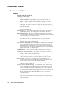
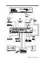
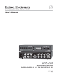
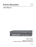
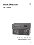
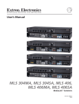
A typical System 7SC application
1-2
System 7SC • Introduction
DI
Z
Oh
R
WE
PO
DE
MO
AP
P/A
SC
A
m
T
RG
B
40
8
O
Extron RGB 508
with SCP/AAP A
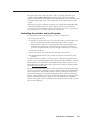
The System 7SC scales composite video, S-video, and component video up to
computer-video (RGBHV/RGBS/RGsB), which can be output to two display
devices via individually buffered BNC and 15-pin HD ports. The System 7SC offers
one fixed level (preamp) stereo audio output and one variable level stereo audio
output.
Rear panel ports allow connection of remote control keypads, the IR Emitter and/
or the optional IR Broadcaster, an optional display power sensor, hardwired
projector control, and an RS-232 controller. The System 7SC also has a power port
to provide power for accessories such as SCP control pads.
Controlling the switcher and an A/V system
The System 7SC can be controlled using one or more of these items:
• The front panel controls.
• A computer, a touch screen panel, or any other device that can send and receive
the serial communications through the RS-232 port. Extron’s Simple
Instruction Set™ (SIS™) is a set of simple keystroke commands that can be
used with any such devices, and Extron’s control software for Windows
provides a graphical interface for controlling the switcher from a computer.
• A contact closure device.
• Extron control pads, such as the SCP 250, SCP 200, or SCP/AAP A.
• The included IR 701 remote control, which can perform all of the front panel
functions.
For the System 7SC switcher to control a projector, it must be programmed. The
switcher can be programmed by having it learn projector IR commands, or Extron’s
IR/RS-232 library of commands can be loaded into the switcher’s memory. The
IR/RS-232 library and the latest control software are available on the Extron Web
site at http://www.extron.com.
The System 7SC learns new projector control commands from infrared (IR) signals
it receives via its front panel IR port or from commands input via an RS-232 device.
These commands are stored in the switcher’s memory and assigned to the front
panel control (Display Power, Display Mute, Mode, Room 1, Room 2) and input
buttons. When a button is pressed, the switcher transmits the stored signals to the
projector via the IR comm port or the projector control RS-232 port. The IR 701,
optional control pads, and/or an RS-232 control system can also be used to execute
these stored commands.
System 7SC • Introduction
1-3
Introduction, cont’d
Features and Options
Features
350 MHz (-3dB) video bandwidth
Configurable video inputs —
• Inputs 1 to 6 — Six sets of 5 BNC connectors on the rear panel accept
RGBHV/RGBS/RGsB computer video, component video, S-video or
composite video input, and are individually configurable.
• Input 7 — Input 7 (on the front panel) includes a VGA-type 15-pin HD
connector for RGB computer video input, a 4-pin mini DIN connector for Svideo input, and one RCA connector for composite video input. Input 7 can
be configured for one of these video formats, or it can be set to automatically
detect the active input.
This input is buffered and can drive a signal approximately 50 feet (15
meters) using Extron cable.
Switcher slaving — Input 1 can be used to connect and control a slaved switcher,
expanding the capacity of the System 7SC to a maximum of 16 inputs.
Buffered video outputs — Five rear-panel BNC connectors and one VGA-type
15-pin HD port provide connections for RGB output. Both outputs (the BNCs
or the 15-pin HD port) are active at all times.
Seven balanced or unbalanced stereo audio inputs — The front panel mini stereo
jack or RCA connectors (for unbalanced input only), and six rear panel
captive screw connectors accept audio inputs. Each input’s gain and
attenuation levels can be individually set.
Two balanced or unbalanced stereo audio outputs — One fixed line level output
(for a recording device) and one variable line level output (for use with an
amplifier or mixer) are provided on 3.5 mm, 5-pole captive screw terminals.
The variable line level output can be controlled via the front panel, the IR 701,
optional control pads, or an RS-232 system.
Audio breakaway — Audio and video can be switched separately via RS-232.
Four ways to control the switcher — The switcher’s front panel, a computer or
other RS-232 control device, the included IR 701 remote control, or a remote
keypad can all be used to control the switcher.
RS-232 configuration — The System 7SC can be configured by using the Extron
control software for Windows, or by using a third party control system.
Room controls — Two relays are provided for controlling lights, window
coverings, a display screen or another item in the room. The Room control
buttons can be set to also send an IR or RS-232 command.
Projector control — The System 7SC can control the projector’s display power,
video mute and mode functions.
Projector control command learning — The switcher can “learn” new projector
control commands by storing IR signals it receives through the front panel,
via files downloaded from Extron’s command library, or from commands
entered via the Windows-based control program. Learned commands can be
associated with any of the front panel input selection or control buttons, and
they are output through the IR Emitter/IR Broadcaster or the projector
control RS-232 port.
Inactivity projector shutdown timer — Using the included control software, the
switcher can be set to monitor the time elapsed since the last input selection
(or other function) and to send a command to turn the projector off after a set
period of inactivity.
1-4
System 7SC • Introduction
Triple-Action Switching™ — With this method, a blank screen is displayed while
the System 7SC switches between inputs.
Built-in video scaler — This feature scales all composite, S-video and component
video signals up to computer-video rates for output on RGB display devices.
Accu-RATE Frame Lock™ — The Extron Accu-RATE Frame Lock™ (patent
pending) eliminates artifacts from scaled motion video by eliminating frame
rate conversion. It locks the output frame rate to the input frame rate of the
active input. The result is a switching system that eliminates image tears and
other artifacts from motion video.
Dynamic Motion Interpolation™ (DMI™) — This video processing technique is an
advanced motion prediction and compensation method that treats motion
content and still content with different algorithms to yield high fidelity images.
3:2 pulldown detection for NTSC and 2:2 film detection for PAL video sources —
These advanced film mode processing features help maximize image detail
and sharpness for video sources that originated from film. When film is
converted to NTSC video, the film frame rate has to be matched to the video
frame rate in a process called 3:2 pulldown. Jaggies and other image artifacts
can result if conventional deinterlacing techniques are used on film-source
video. The System 7SC’s advanced film mode processing recognizes signals
that originated from film. The System 7SC then applies video processing
algorithms that optimize the conversion of video that was made with the 3:2
pulldown process. This results in richly detailed images with sharply
defined lines. A similar process is used for PAL film-source video.
Versatile mounting options — The System 7SC can be rack mounted, or it can be
placed on a table or other furniture. Rubber feet and rack mounting
hardware are included.
Options and accessories
The System 7SC’s optional equipment expands a user’s ability to control system
devices. Optional equipment includes:
• Display power sensor — This sensor (part #60-271-01) detects whether the
projector’s power is on or off.
• SCP control pads — Up to sixteen (16) Extron SCP/AAP A, SCP 200, and/or
SCP 250 control pads can be connected via a rear panel port. Each SCP
replicates some or all of the System 7SC’s front panel controls.
• IR Broadcaster — The Extron IR Broadcaster (part #60-272-02) has a greater
range than the IR Emitter and transmits signals over a wide area.
System 7SC • Introduction
1-5
Introduction, cont’d
1-6
System 7SC • Introduction
System 7SC
2
Chapter Two
Installation
Mounting the Switcher
Cabling and Panel Views
Connecting and Slaving a Switcher
Labeling Buttons on the System 7SC and SCPs
Installation
Mounting the Switcher
Tabletop use
The System 7SC comes with rack mounting brackets and rubber feet. For tabletop
use, attach a self-adhesive rubber foot to each corner of the bottom of the unit.
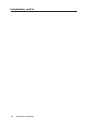
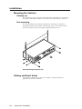
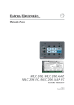
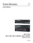
Rack mounting
For rack mounting, do not install the rubber feet. Attach the provided rack
mounting brackets to the switcher with machine screws, as shown below, then
fasten the switcher to the rack using the supplied machine screws.
VO
IG
BR
CO
LO
R
TIN
HT
CO
NT
T
MEN
ER
AIL AD
DET
JU
NEX
T
Y
LA
ME
C
EM
IR
U
LU
ST
RX
N
AR
LE
7S
ST
SY
DISP
TX
RX
UT
MP
CO
T7
INPUDIO
AU
R
O
DE
S-VI
L
O
VIDE
CO
P
DIS
R
PW
P
DIS
TE
MU
NTR
OL
DE
MO
OM
RO
1
OM
RO
2
7
6
5
4
3
2
1
Rack mounting the System 7SC
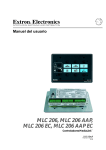
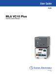
Cabling and Panel Views
The diagram on the next page shows an example of a typical System 7SC
application and cable connections.
2-2
System 7SC • Installation
CONTROL
DISP
PWR
DISP
MUTE
MODE
ROOM
1
ROOM
2
COLOR TINT
BRIGHT CONT
DETAIL
ADJUST
VOLUME
MENU
1
2
3
4
5
6
7
NEXT
DISPLAY
INPUT 7
VIDEO
VIDEO
S-VIDEO
S-VIDEO
AUDIO
LL
COMPUTER
IR
RX LEARN
TX
RX
RR
SYSTEM 7SC
System 7SC
Front Panel
Laptop
Computer
Laptop
Computer
Current
Sensor
AC
Power
POWER SENSOR
Display
Power
Sensor
Document
Camera
RGB 440
Plasma Display
VCR
Projector
OUTPUTS
INPUTS
Anaheim, CA
100- 240
50/60 Hz
1.3A MAX.
R
R-Y
H/HV
R
R-Y
H/HV
R
R-Y
H/HV
R
R-Y
H/HV
R
R-Y
H/HV
R
R-Y
H/HV
G/Y
VID
V
G/Y
VID
V
G/Y
VID
V
G/Y
VID
V
G/Y
VID
V
G/Y
VID
V
1
2
3
4
B/C
B-Y
AUDIO OUT
B/C
B-Y
B/C
B-Y
AUDIO IN
B/C
B-Y
FIXED
L 1 R
L 2 R
L 3 R
L 4 R
L 5 R
L 6 R
L
VARIABLE
R
L
5
G
B
H/HV
V
Host Computer/
RS-232 Control
System
6
B/C
B-Y
B/C
B-Y
1
RS-232
RGB
SCP/AAP CONTROL
A B CD E A B CD E
R
R
ABCDE
A B CD E A B CD E
1 2 3 4 5 6 7
2
CONTACT CLOSURE
RELAY 1
RELAY 2
DISPLAY PWR
SENSOR
IR COMM
A B C D E F G H I J
PROJ CONTROL
System 7SC
Rear Panel
IR Emitter
or
Emitter
Comm.
IR BROADCASTER
Recording Device
Audio Amplifier
IR Broadcaster
Lighting
Shades/drapes
Room Control
VCR
H. SHIFT
HIGH Z
SHOW ME
MAX/
MIN
AUTO
AUDIO
AUDIO
VOLUME
75 Ohm
POWER
INPUT
POWER
Computer
DISPLAY
MUTE
MODE
Doc. Camera
SCP / AAP A
DISPLAY
POWER
MUTE
AUDIO
DVD Player
MAX/
MODE
IR
MIN
VOLUME
RGB 508
WITH ADSP TM
player
Dis
Pow
RGB 508 with
SCP/AAP A
Con
trol
Func
tions
play
te
DisMu
te
Mu
Inpu
o
e
um
Vol
2
6
m
Roo
0
Audi
de
Mo
1
5
9
t Selec
tion
3
4
7
1
m
Roo
8
ROOM
1
ROOM
2
1
2
3
4
5
6
7
2
TER
EN
R
LO
CO
IFT
SH
T
TIN
ge
Ima
NT
CO
Contact Closure
Keypad
T
IGH
BR
nts
me
just
Ad
IL
TA
DE
Sy
ste
1
70 te
mo
Re
IR
m
IR 701 Remote
SCP 250
SCP 250
System 7SC • Installation
2-3
Installation, cont’d
Power, video, and audio conections
With the exception of input 7 on the front panel, all input and output connectors
are on the rear panel.
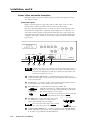
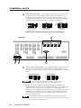
Front panel inputs
Input 7 on the front panel accepts video and one audio input. Only one video
format and one audio port will be active at a time on the front panel.
The active input type (RGB, S-video, or composite video) can be selected via the
LCD menu (see chapter three, “Operation and Configuration”, for details), or, in
autoselect mode, the System 7 automatically detects the active video signal and
selects that video signal format. If all formats are active, the default will be RGB
computer video input. An LED near each video connector indicates which input
type is active.
COLOR TINT
BRIGHT CONT
DETAIL
ADJUST
VOLUME
MENU
DISPLAY
INPUT 7
VIDEO
VIDEO
S-VIDEO
S-VIDEO
AUDIO
LL
1
2
COMPUTER
IR
RX LEARN
TX
RX
RR
3
NEXT
4
SYSTEM 7SC
5
If the autoselect feature is on, and input 7 is selected, and all ports for input 7
have active video signals, then the 15-pin HD computer video (RGB) port will
be selected as the default source. Both input 7 and the autoselect feature must
be selected for autoselect to be active.
1
Composite video (Video) port — This female RCA-type connector is for
composite video input. In autoselect mode, the composite video input will be
set for motion mode.
2
S-video port — Connect an S-video source to this 4-pin mini DIN connector.
In autoselect mode, S-video will be set for motion mode.
3
RCA audio port — Connect the left audio signal cable to the
white RCA connector (L), and the right signal cable to the
red RCA connector (R) for unbalanced stereo audio input.
Wire the RCA plugs as shown at left.
Tip Sleeve (GND)
Connect an active audio input to only one audio port
– either the RCA port or the PC port.
4
PC audio port — This 3.5mm mini stereo jack is
for unbalanced, computer level stereo audio
input. Wire the plug as shown at right.
Connect an active audio input to only one audio
port – either the PC port or the RCA port.
5
2-4
Tip (L)
Sleeve (GND)
Ring (R)
Tip (L)
Sleeve (GND)
Computer video (RGB) port — Connect a computer video (RGBHV, RGBS,
RGsB, or RsGsBs) source via this VGA 15-pin HD connector. By default pins
4, 10, and 11 are grounded for ID bit termination.
System 7SC • Installation
Input 7 is buffered and can drive a signal approximately 50 feet (15 meters)
using Extron cable.
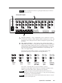
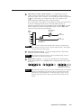
Rear panel inputs
1
2
INPUTS
Anaheim, CA
100- 240
50/60 Hz
1.3A MAX.
R
R-Y
H/HV
R
R-Y
H/HV
R
R-Y
H/HV
R
R-Y
H/HV
R
R-Y
H/HV
R
R-Y
H/HV
G/Y
VID
V
G/Y
VID
V
G/Y
VID
V
G/Y
VID
V
G/Y
VID
V
G/Y
VID
V
1
2
3
4
FIXED
L 1 R
L 2 R
L 3 R
L 4 R
L 5 R
5
L 6 R
L
R
SCP/AAP CONTROL
E D CB A E D C B A
VARIABLE
L
6
B/C
B-Y
B/C
B-Y
B/C
B-Y
AUDIO OUT
B/C
B-Y
B/C
B-Y
AUDIO IN
B/C
B-Y
R
1
1 2 3 4 5
2
CONTACT C
3
1
AC power connector — Plug a standard IEC power cord into this connector
to connect the switcher to a 100 to 240VAC, 50 Hz or 60 Hz power source. The
front panel control and input selection buttons will light in sequence during
power-up.
2
Video inputs 1 through 6 — These inputs accept computer video (RGB),
component video, S-video, or composite video signals. The front panel input
selection button lights steadily when the corresponding input is selected. If
audio breakaway is active, the front panel input selection button corresponding to the audio input source blinks, and the button corresponding to the
video source lights steadily.
Each input has 5 female BNC connectors. Connect the cables for the
appropriate signal type as shown in the following illustration.
R
R-Y
H/HV
R
R-Y
H/HV
R
R-Y
H/HV
R
R-Y
H/HV
R
R-Y
H/HV
R
R-Y
G/Y
VID
V
G/Y
VID
V
G/Y
VID
V
G/Y
VID
V
G/Y
VID
V
G/Y
VID
B/C
B-Y
RGBHV
input
B/C
B-Y
RGBS
input
B/C
B-Y
RGsB
input
B/C
B-Y
B/C
B-Y
H/HV
V
B/C
B-Y
Component
video input
S-video
input
Composite
video input
(R-Y, Y, B-Y)
(Y, C)
(Video)
For S-video, connect the luma (Y) signal to the BNC connector
marked G/Y/Vid, and the chroma signal (C) to the BNC marked B/C/B-Y.
A BNC-to-4-pin mini DIN (S-video) adapter may be required.
Configure each input’s video format via the front panel LCD menu (see
chapter three, “Operation and Configuration”) or using RS-232 programming
(see chapter four, “Serial Communication”).
If a slave switcher will be used, the output of that switcher must be connected
to input 1 of the System 7SC.
System 7SC • Installation
2-5
Installation, cont’d
3
Audio inputs 1 through 6 — Each input has a 3.5 mm, 5-pole captive screw
connector for balanced or unbalanced stereo audio input. Connectors are
included with each System 7, but the user supplies the audio cable. See the
following wiring diagrams to wire a connector for the appropriate input type
and impedance level. High impedance is generally over 800 ohms.
600 ohms
R
AUDIO
Tip
Ring
Sleeve (s)
Tip
Ring
L
AUDIO
R
R
L
L
Tip
Sleeve
Tip
Ring
Sleeve (s)
Tip
Ring
AUDIO
Tip
Sleeve
600 ohms
Unbalanced Input
Balanced Input
Balanced Input
(high impedance)
(high impedance)
(600 ohms)
Captive screw connector wiring for rear panel audio inputs
Outputs
4
OUTPUTS
INPUTS
R
R-Y
H/HV
R
R-Y
H/HV
R
R-Y
H/HV
G/Y
VID
V
G/Y
VID
V
G/Y
VID
V
4
5
FIXED
L
R
1
L
R
1
B
H/HV
V
RS-232
RGB
SCP/AAP CONTROL
E DCBA E D CB A
VARIABLE
G
6
B/C
B-Y
B/C
B-Y
B/C
B-Y
AUDIO OUT
R
1 2 3 4 5 6 7
2
A B CD E A B CD E
CONTACT CLOSURE
2
RELAY 1
RELAY 2
E DCBA
DISPLAY PWR
SENSOR
IR COMM
A B C D E F G H I J
PROJ CONTROL
3
1
Line level audio output (Fixed) — For unamplified audio output, connect an
audio device, such as an audio recorder, VCR, or powered speakers, to this
3.5 mm, 5-pole captive screw connector. Follow the diagram below for correct
wiring.
Unbalanced Output
Balanced Output
AUDIO
R
Tip
Ring
Sleeve (s)
Tip
Ring
L
R
AUDIO
L
Tip
See Warning
Sleeve (s)
Tip
See Warning
Connect the sleeve to ground (Gnd). Connecting the sleeve to a
negative (-) terminal will damage the audio output circuits.
The gain can be set separately for each input channel so that there is no
audible difference in level when switching between inputs. See chapter three,
“Operation and Configuration”, for information on adjusting the audio
output level via LCD menu and front panel controls. See chapter four, “Serial
Communication”, for information on using the Simple Instruction Set (SIS)
commands and the Windows-based control program to adjust audio levels
and to set audio breakaway.
The Fixed audio output and the Variable audio output are simultaneously
active, therefore two devices can be connected at the same time. Both outputs
carry the same input’s audio signal.
2-6
System 7SC • Installation
2
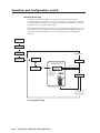
Adjustable level audio output (Variable) — For adjustable level audio
output, connect an audio device, such as an amplifier, or mixer, to this 3.5
mm, 5-pole captive screw connector. Follow the diagram and warning shown
in 1 for correct wiring. See chapters three and four for details on perchannel input gain adjustments and on audio breakaway.
The overall level for this output is controlled by the front panel Volume knob.
As shown in the diagram below, the volume adjustment applies an
attenuation after the per-input gain adjustments discussed in 1 are applied.
For this output the volume level adjustments apply to all the inputs and
cannot be set separately per input channel.
Master (Volume)
adjustment
Audio
inputs
1
2
3
4
5
6
7
Variable
audio output
Fixed
audio output
Per-input
gain adjustment
The Fixed audio output and the Variable audio output are simultaneously
active, therefore two devices can be connected at the same time. Both outputs
carry the same input’s audio signal.
3
Output 15-pin HD connector — Connect a display device to this female
VGA-style connector for RGB output.
Both outputs are buffered and can be connected simultaneously. The sync
format will be the same for both outputs.
4
Output BNC connectors — Connect coaxial cables from another display
device to these BNCs for one RGBHV, RGBS, or RGsB/RsGsBs video output
as follows:
R
G
B
RGBHV
H/HV
V
R
G
B
RGBS
H/HV
V
R
G
B
H/HV
V
RGsB (Sync on Green)
RsGsBs (output only if input is RsGsBs)
Both outputs are buffered and can be connected simultaneously to two different
displays. For RGB inputs, the output signal’s sync format is based on the
format of the incoming RGB signal. For all other types of inputs, the user
selects the output sync format. The sync format will be the same for both
outputs.
System 7SC • Installation
2-7
Installation, cont’d
Control device connections
Captive screw and 3.5 mm stereo jack connectors are included with the
switcher, but the installer provides the cables.
OUTPUTS
R
R-Y
H/HV
R
R-Y
H/HV
G/Y
VID
V
G/Y
VID
V
5
B
H/HV
V
7
RS-232
RGB
SCP/AAP CONTROL
E D CB A E D CB A
1
G
6
B/C
B-Y
B/C
B-Y
1 2 3 4 5 6 7
2
CONTACT CLOSURE
1
1
R
2
E DCBA
A B C D E A B C D E
RELAY 1
RELAY 2
3
DISPLAY PWR
SENSOR
IR COMM
4
5
ABCDE FGH I J
PROJ CONTROL
6
SCP/AAP Control ports — Connect Extron SCP control pads (SCP 250,
SCP 200, or SCP/AAP A) to these 5-pole captive screw connectors to provide
remote control of the System 7SC. The SCPs replicate several of the front
panel controls. The SCP 200 and SCP 250 are also able to receive infrared
signals from the IR 701 remote control and send them to the switcher.
In total, up to sixteen (16) control pads in any combination can connected to
these ports if they are linked together with cables such as Extron’s Comm
Link cable. Refer to the appropriate SCP user’s manual for details and wiring
diagrams.
The SCP/AAP Control port has the following pin assignments:
SCP/AAP CONTROL
E D CB A E D CB A
1
2
A
B
C
D
E
Ground (shield/drain)
Comm. signal (white)
Ground (black)
+12VDC (red)
To / from
SCP 200,
SCP 250,
or SCP/AAP A
Each port provides up to 12VDC for powering the SCP control pads or other
devices. However, the total load for both ports combined must not exceed
1 ampere.
The load (such as an SCP control pad or interface) should not be placed further
than a maximum of 300 feet (91.4 meters) from the System 7SC switcher.
2
2-8
Contact closure — Connect an optional contact closure control device here.
Select an input channel by making contact closure between an input’s pin
(pins 1 through 7 correspond to inputs 1 through 7) and a ground pin (pins 8,
9, and 10). Continuous connections made by contact closure override all other
means of selection: continuous contact closure takes precedence over front
panel and RS-232 selection.
System 7SC • Installation
3
Room/relay ports (Relay 1, Relay 2) — These allow control of “room”
functions – items such as room lighting, window coverings, and display
screens – via momentary or latching contact. These contacts may be used to
control any equipment as long as the contact specifications of a total of
24 volts at 1 ampere are not exceeded for each port.
Normally closed (2)
Normally closed (1)
Normally open (2)
Normally open (1)
Each relay has two sets of contacts: one pair is closed by default, the other pair
is open by default, as shown below. Both of a relay’s contacts can be used at
the same time, so a total of four sets of contacts can be used simultaneously.
A B C D E A B C D E
System 7SC
Relay ports
Not
used
RELAY 1
RELAY 2
E
D
C
B
A
Normally closed (2)
Normally closed (1)
Normally open (2)
Normally open (1)
Not used
To / from
room control
equipment
When the room function is active, the closed contacts open, and the open
contacts close. Contacts can be programmed to operate in one of two ways:
• latching (brief contact) (press to turn on, press to turn off), or
• momentary (timed) (press to turn on, timeout to turn off).
In the timed mode the default timeout period is 1/8 second. Use the front
panel menus or the control software for Windows to change the length of the
timeout period. See “Serial Communication”, chapter four, for details.
4
Display power sensor port — This mini stereo-style jack allows connection
of an optional display power (current) sensor (part #60-271-01). The sensor is
used to keep the projector and the System 7SC in sync. Refer to the Power
Sensor User’s Guide, part #68-391-01, for information on operating the sensor.
The power sensor port supplies +12VDC. To avoid electric shock when
connecting the cable from the power sensor into the System 7’s rear panel
port, always connect the stereo jack at one end of the cable to the power
sensor unit before plugging the jack at the other end into the System 7.
The wiring connections are the same on both ends of the cable that connects
Sleeve (GND)
the power sensor to the System 7.
Wire the included connector as shown at left.
Use a 3-wire cable.
Ring (signal)
p (+12V)
Tip (+12V)
Sleeve (GND)
5
IR communications port (IR Comm) — Connect the included IR Emitter or
optional IR Broadcaster via this captive screw connector to send learned/
uploaded IR signals (which differ from IR 701 remote control signals) to
control the projector. The signals from the optional IR Broadcaster cover a
wider area and greater distance than do those from the emitter, so it can be
placed further from the projector.
System 7SC • Installation
2-9
Installation, cont’d
The pin assignments are as follows:
A
B
C
D
E
Signal
Display power/current sensor detection
Carrier & signal
Gnd
+12V
Wire the connector using one of the following wiring options.
E D C B A
IR COMM
System 7
IR Comm
port
White striped wire only
IR
Emitter
C Carrier & signal
Gnd*
D
For the IR Emitter only
E D C B A
IR COMM
System 7
IR Comm
port
C Carrier & signal
Gnd
D
+12V
E
To IR Broadcaster
with emitter port
(#60-272-02)
For the IR Broadcaster with emitter port
E D C B A
IR COMM
System 7
IR Comm
port
Sleeve
(Gnd)
A
Signal
D
Gnd
Tip
(signal)
To projector's
wired remote
port
For a wired projector remote port
IR Communications port wiring options
For some projectors the emitter must be used together with the IR Broadcaster.
Refer to the IR Broadcaster User’s Guide (part #68-392-02) or contact an
Extron support representative for details.
6
Projector control port — Connect a cable between the projector and this
3.5 mm, 10-pole captive screw connector for RS-232 or RS-422 one- or twoway projector/display device control. Commands from a downloaded
projector control program or user-defined command strings entered via the
Windows-based control program can be sent to the display device from this
port.
Use the illustration below as a guide to wiring the connector. Wiring will vary
depending on the projector model. In most cases only the transmit (Tx) and
ground connections will be needed.
2-10
System 7SC • Installation
Tx
A B CD E F GH I J
PROJ CONTROL
NOTE
I
H
G
F
E
D
C
B
A
Each projector/display may require
different wiring. For wiring details, see the
UC cable wiring and pin assignments
illustration, and refer to the manual that
came with the projector.
*
*
*
*
Ground (Gnd, )
*
Transmit (Tx)
*
*
To / from
projector
We recommend using the UC 50’ universal projector control cable (included
with the System 7SC) for this connection. One end of the cable is terminated
with a female 9-pin D connector, and the other end is unterminated. The
UC 50’ pin assignments are as shown in the following illustration. Refer to
the projector’s manual for the projector’s pin assignments in order to
determine which of the cable’s wires to connect to which of the System 7’s
projector control port pins.
To the
switcher
Black
Grey
Purple
Blue
Green
Yellow
Orange
Red
Brown
9
8
7
6
5
4
3
2
1
1
5
UC Cable
To the
projector
Connector Shell
Shield
Color Pin #
6
9
UC 50', 100', 200' Cable Color Codes
Two categories of projector control files are sent via this port: RS1 and RS2.
Both types make it possible to control a projector’s power, mute, and input
selection functions.
RS1 files are for unidirectional (talk only) communication from the switcher
to the projector. RS1 requires only wiring the ground pins, the
switcher’s transmit pin, and the projector’s receive pin. Refer to the
following table and to the projector’s manual for wiring instructions.
RS1 (unidirectional communications) wiring —
used with user-defined and RS1 Extron files
Pin
I
E
C
NOTE
RS-232
RS-422
n/a
Ground
Transmit (Tx)
Transmit - (Tx-)
Ground
Transmit + (Tx+)
Each projector/display may require different wiring. For details, refer to
the manual that came with the projector.
RS2 files are for bidirectional (talk and listen) communications between the
switcher and projector. Transmit, ground, and receive pins must be
wired for RS2 communications. Except for the ground connection, RS2
wiring is projector-specific. Refer to the projector’s manual for details or
call the Extron S3 Sales and Technical Support Hotline if needed.
7
RS-232 port — This connector provides for two-way RS-232 communication.
See the “Serial Communication” chapter for information on how to install and
use the control software and SIS commands.
System 7SC • Installation
2-11
Installation, cont’d
The default protocol is 9600 baud, 1 stop bit, no parity, and no flow control.
The rear panel RS-232 9-pin D connector has the following pin assignments:
Pin RS-232 function
1
2
3
4
5
6
7
8
9
–
Tx
Rx
Tx 2
Gnd
–
–
Rx 2
–
Description
No connection
Transmit data
Receive data
Transmit data
Signal ground
No connection
No connection
Receive data
No connection
5
1
9
6
DB9 Pin Locations
Female
Pins 4 and 8 (Tx2 and Rx2) are used to communicate with a slaved switcher (if
one is connected). A slave adapter cable (Extron part #26-386-01) is required
for slaving. For details, see “Connecting and Slaving A Switcher” in this
chapter, and also see “Switcher Setup/Configuration” in chapter three.
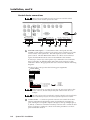
Connecting and Slaving a Switcher
One switcher can be connected (slaved) to the System 7SC to allow for a greater
number of inputs. The System 7SC serves as the master switcher, communicating
with and providing video output to the projector/display. The switcher (“slave”)
that is connected to the System 7 provides up to ten (10) additional input
connections. See the illustration below for a list of Extron switchers that can be
used as slaves.
A System 7SC cannot be used as a slaved switcher.
The RS-232 and video cable connections must be made between the slaved
switcher and the System 7 before the System 7 can be configured (via front
panel or RS-232) for slaving.
Do not attach any communications or control devices to the slaved switcher
except a contact closure remote control, if one is needed.
To connect a slave switcher to the System 7SC, do the following:
1.
2-12
Connect the slave switcher’s video and audio outputs to input 1 of the
System 7SC. See “Rear panel inputs”, page 2-5, in this manual, and refer to
the slave switcher’s user’s manual for details on cabling.
System 7SC • Installation
System 7SC Rear Panel
OUTPUTS
INPUTS
Anaheim, CA
100- 240
50/60 Hz
1.3A MAX.
R
R-Y
H/HV
R
R-Y
H/HV
R
R-Y
H/HV
R
R-Y
H/HV
R
R-Y
H/HV
R
R-Y
H/HV
G/Y
VID
V
G/Y
VID
V
G/Y
VID
V
G/Y
VID
V
G/Y
VID
V
G/Y
VID
V
1
2
B/C
B-Y
3
B/C
B-Y
AUDIO IN
4
B/C
B-Y
L 1 R
L 2 R
L 3 R
L 4 R
L 5 R
5
B/C
B-Y
AUDIO OUT
FIXED
L 6 R
L
R
L
R
1
G
B
H/HV
V
B/C
B-Y
2
A B CD E
IR TRANSPORT
RS-232
RGB
1 2 3 4 5 6 7
CONTACT CLOSURE
E DCBA
A B CD E A B CD E
RELAY 1
DISPLAY PWR
SENSOR
RELAY 2
IR COMM
A B C D E F G H I J
PROJ CONTROL
Slave Cable
Extron part
# 26-386-01
These Extron switchers can be slaved to
the System 7SC:
• System 8 PLUS
• SW4 AR MX HV
• System 10 PLUS
Host
Computer
6
B/C
B-Y
SCP/AAP CONTROL
E D CB A E D CB A
VARIABLE
R
• SW 6 AR MX HV
90-240 VAC, 50/60 Hz
FUSE: 250V, 400mA SLO-BLO
1
3
INPUTS
5
6
4
2
INPUTS
Slave Switcher
Rear Panel
VCR
DVD
Computer
The System 7SC master connected to a slaved switcher
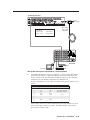
2.
Connect the RS-232 ports of the two switchers. A slave adapter cable (Extron
part number 26-386-01), is required for RS-232 connection. This allows the
master (System 7), the slaved switcher, and the host device to be connected
simultaneously. The RS-232 communication is bidirectional.
The pin assignments for each of the slave cable’s three 9-pin connectors are as
follows:
Pin
System 7
Host
Slave switcher
1
2
3
4
5
6
7
8
9
–
Tx
Rx
Tx 2
Gnd
–
–
Rx 2
–
–
Rx
Tx
*Tx 2
Gnd
–
–
*Rx 2
–
–
Tx 2 (slave to host)
Rx 2 (host to slave)
–
Gnd
–
–
–
–
* Pins 4 and 8 on the host connector must be used for Tx2 and Rx2 only, and
not for other signals in the host system. If needed, disable or disconnect
pins 4 and 8 on the host side.
System 7SC • Installation
2-13
Installation, cont’d
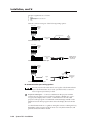
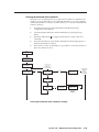
3.
For a System 8 PLUS or System 10 Plus switcher, set the slaved switcher to
master mode. On the slaved System 8 PLUS or System 10 Plus switcher,
locate the Address DIP switches on the back panel, and set switches #1, 2, 3, 4,
and 5 up.
4.
Power on the slaved switcher and the System 7SC.
5.
From within Add Slave? in the System 7SC’s Switcher Setup/Configuration
menu, select the slave switcher type and size. See chapter three, “Operation
and Configuration”, for information on using the menus.
6.
Use the front panel buttons and menus or the host computer to configure the
video formats for the slaved switcher’s inputs. See chapter 3, “Operation and
Configuration”, for details on how to configure inputs. The inputs of the
slaved switcher do not have to all be the same video signal type. Each input
can be configured in the System 7 for a different signal type (RGB, component
video, S-video, composite video), as long as the slaved switcher can handle
those signals. As for the System 7SC’s direct inputs, IR and RS-232 commands
can also be associated with the slaved inputs.
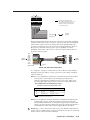
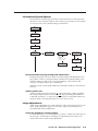
Once the slaved switcher is connected and configured, its inputs will be the
System 7’s first inputs (input 1 through input 2, 4, 6, 8, or 10). Input 2 of the
System 7 becomes the next input (input 2, 5, 7, 9, or 11).
For example, if a six-input switcher is slaved to the System 7, the slaved switcher’s
six inputs are inputs numbers 1, 2, 3, 4, 5, and 6. The inputs labeled as 2 through 6
on the System 7’s rear panel and 7 on the front panel become inputs 7 through 12,
as shown in the illustration on the next page.
Inputs 7 thru 12
CONTROL
Slave
Cable
DISP
PWR
DISP
MUTE
MODE
ROOM
1
ROOM
2
1
7
8
9
10
11
12
INPU
VIDEO
S-VIDEO
AU
L
Inputs 1 thru 6
1
2
3
4
5
6
Slaved
Switcher
Example of input numbering with a six-input slaved switcher
To select an input from the slaved switcher, press the appropriate button on the
slaved switcher, or use the RS-232 controller or host computer. Pressing the input 1
button on the front panel of the System 7 selects input 1 of the slaved switcher.
Labeling Buttons on the System 7SC and SCPs
You may wish to customize the labeling of the System 7SC’s front panel buttons or
to make labels for any SCP 200 or SCP 250 control pads that are part of the
installation. Premade templates and blank templates for the SCP faceplates’ label
windows are printed in the SCP/AAP A, SCP 200, SCP 250 User’s Manual. However,
you can easily create, customize, and print labels for the switcher’s buttons or the
SCPs’ button label windows by using the Button-Label Generator software.
2-14
System 7SC • Installation
Button-Label Generator software
The Extron Button-Label Generator program (Buttons.exe) is included with the
System 7SC, and it can also be downloaded from the Extron Web site
(http://www.extron.com). This program is used to create and print labels that can
be inserted into the illuminated pushbuttons or placed in slots above/below
buttons on the SCPs and on various Extron switchers.
Installing the software
This program is installed at the same time the System 7SC control program is
installed. No additional steps are required. See page 4-11 of this manual for
installation instructions.
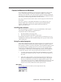
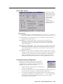
Using the software
1.
To run the Button-Label Generator program, double-click on the Button-Label
Generator icon (shown at left) in the Extron Electronics group or
folder, and click OK when prompted.
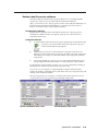
2.
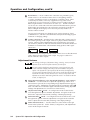
Under System selection, choose the item that corresponds to the device for
which you want to make labels: System 7SC, SCP 200, or SCP 250. The button
label editing area changes to reflect the number and arrangement of buttons
on the device.
3.
Using normal Windows controls, you can create and print labels that can be
cut out and placed in the label windows on the front panel of the switcher.
For information about using the program, you can access a help file by clicking on
the Help menu on the main screen and choosing Show Help.
You can also see an example of a completed Extron’s Button-Label Generator
window by clicking on the Help menu on the main screen, choosing Show Help, and
clicking on the Load Demo button.
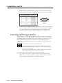
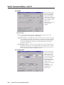
The following pictures are examples of what the Button-Label Generator screens
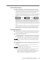
look like when set for the System 7SC, the SCP 200, and SCP 300.
System 7SC button label screen
SCP 200 button label screen
System 7SC • Installation
2-15
Installation, cont’d
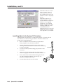
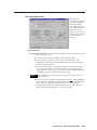
Each button label can contain
from 1 to 3 lines of text (or
none) with choices for each
line of different font sizes and
whether to center or left justify
the text.
SCP 250 button label screen
Each button label can also
contain a picture (or none)
selected either from the Device
Palette or a user-supplied
graphic file. User-supplied
graphics should be icon (.ICO)
or bitmap (.BMP) files. Files
called TEST.BMP and
DEMO_BTN.DAT are installed
with this program as examples,
and a help file is also included.
Installing labels in the System 7SC’s buttons
Label installation for the SCPs is covered in the SCP/AAP A, SCP 200, SCP 250
User’s Manual. Use the following procedure to install new labels in the
System 7SC’s front panel buttons.
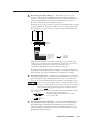
2-16
1.
Remove the button from the switcher: grasp the button
firmly and pull it away from the front panel.
2.
Separate the grey backing from the clear plastic cap by
inserting a flat blade screwdriver into the slots and twisting
it, as shown at right.
3.
Save the translucent, white backing plate, but remove the
text insert.
4.
Make new labels by using the Button-Label Generator
software (see pages 2-14 and 2-15). Print and cut them out.
5.
Insert a button label and the white backing plate into the
cap and reassemble the button. Press the cap onto
the grey backing gently but firmly.
6.
Press the button into place in the switcher.
System 7SC • Installation
Screwdriver
TE
XT
System 7SC
3
Chapter Three
Operation and Configuration
Front Panel Features and Basic Operation
IR and RS-232 Projector Control
Optimizing the System
Menus, Configuration, and Adjustments
Remote Control of the System 7SC
_
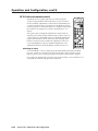
Operation
and Configuration
System 7SC can be set up and operated by using:
• The front panel controls.
• A computer, a touch screen panel, or any other device that can send and receive
the serial communications through the RS-232 port. Extron’s Simple
Instruction Set™ (SIS™) is a set of simple keystroke commands that can be
used with any such devices, and Extron’s control software for Windows
provides a graphical interface for controlling the switcher from a computer.
• A contact closure device.
• Extron control pads, such as the SCP 250, SCP 200, or SCP/AAP A.
• The included IR 701 remote control, which can perform the front panel functions.
Some settings can be adjusted only through a host computer. For details on serial
communications control via the RS-232 port, see chapter 4, “Serial Communication”.
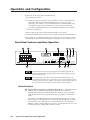
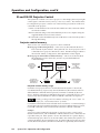
Front Panel Features and Basic Operation
1
2
3
4
5
6
7
CONTROL
DISP
PWR
DISP
MUTE
MODE
1
2
3
ROOM
1
ROOM
2
4
5
COLOR
TINT
BRIGHT CONT
DETAIL
ADJUST
VOLUME
MENU
6
7
DISPLAY
INPUT 7
VIDEO
S-VIDEO
AUDIO
L
8
NEXT
COMPUTER
IR
RX LEARN
TX
RX
R
9
10
SYSTEM 7SC
11
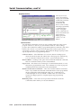
When the System 7 powers up, all of the front panel LEDs light while the
control buttons and then the input selection buttons light briefly in sequence,
then the LEDs turn off.
Each of the front panel buttons can have an RS-232 command and/or an
IR command associated with it. If the button is set up via the Windows-based
control program, pressing an input selection button could select that input and
have the System 7 send an RS-232 command and/or an IR command.
Control features
1
Display buttons: Display Power, Display Mute, Mode — Each of these three
buttons can be configured/programmed to perform or send either an
infrared (IR) command or an RS-232 command. Display Power and Display
Mute each have two memory blocks that can store 256 bytes of information
apiece.
The settings of the display buttons are customized for each projector. These
buttons function only after they have been programmed, either by “learning”
IR commands or by loading projector commands (drivers) from the Extron
IR library. When a display button is pressed or activated by RS-232, one of the
following messages is displayed on the LCD screen:
3-2
System 7SC • Operation and Configuration
DISPLAY
POWER
DISPLAY
MUTE
MODE
If Display Power is on,...
Hold Pwr for 2s
Display Mute
Disp Mute: On
Mode
DISPLAY
MUTE
Release Pwr
If Display Power is on,...
Display Power
Disp Power: On
Display Mute
Disp Mute: Off
Display Power button
To send a power-on command, press and hold the Display Power button
for two seconds. At the end of two seconds, the button will flash twice,
then glow steadily while the display device is on.
If AC power is removed from the switcher while Display Power is on, the
switcher will send an RS-232 power-off command to the display device
before shutting down. The System 7 cannot send a power-off command
via IR after power has been disconnected.
To turn the display device off, again press and hold the Display Power
button for two seconds. The System 7 will send the power-off
command, and the Display Power button will flash twice, then turn off
(go dark). Many projectors require a power-off delay. The System 7 has
a brief power-off delay, during which the power-off command is resent
to the display device.
To shut down the projector if the switcher hasn’t been used for a set
amount of time, a built-in inactivity shutdown timer can be set by using
the included control software. If the inactivity timer is enabled, the
switcher monitors the time elapsed since the last input selection (or
other function) and sends a display power off command (or that
command and any other commands associated with the Display Power
button) after a set period of inactivity. That period can be selected in
fifteen-minute increments to be as long as 480 minutes (8 hours). See
chapter four, “Serial Communication”, for details.
The Display Power button can also have the functions of one of the
Room buttons assigned to it. The associated room function (relay
activation + associated commands) can be executed immediately after
the Display Power IR and/or RS-232 commands are sent. The Room
button will light when the room function is executed.
Display Mute button
Once it has been programmed for use with the projector, press and
release this button to send a mute on/off command to the display device.
The button will not flash before sending the command.
Display Mute is only active when Display Power is on.
Mode button
Press this button to execute any IR or RS-232 command that has been
programmed into its memory. For example, it can be used to switch the
mode of the projector between computer video (RGB), S-video, and
composite video, replicating the 1-button (step) mode function provided
on some projectors’ remote controls.
Each of the Display buttons can be set up to send an IR signal immediately
after sending an RS-232 signal once the button is pressed.
System 7SC • Operation and Configuration
3-3
Operation and Configuration, cont’d
2
Room buttons — Room 1 and Room 2 control the rear panel Relay ports,
which control “room” functions–items such as room lighting, window
coverings, and display screens–via momentary or latching contact. These
contacts may be used to control any equipment as long as the contact
specifications of a total of 24 volts at 1 ampere are not exceeded. The Room
buttons light while the room functions are active (on). Each Room button
can also be set to send an IR or RS-232 command when the button is pressed.
If the Display Power button has a Room function assigned to it, the Room
button will light when Display Power has been pressed, and the room
function will be executed.
See page 2-9 for information on the Relay ports, and see chapter 4, “Serial
Communication”, and refer to the Windows-based System 7SC Help program
for details on changing settings.
7
Volume control knob— Turn this knob to adjust the audio volume (gain) for
the Variable (preamp) audio output. There is no physical limit to this knob’s
rotation. During volume adjustment the LCD screen displays a bar graph
(shown below), which also indicates when the knob has reached its functional
minimum or maximum limit. The minimum setting produces 100% signal
attenuation.
Min
Volume
Max
Min
Volume
Max
Min
Volume
Max
In normal mode (not setup mode) the volume control does not affect the Fixed
audio output, only the Variable audio output. See pages 2-6 and 2-7 for
details on the two audio outputs.
Adjustment features
The settings of each type of adjustment (image, centering, zoom, and volume
adjustments) are stored in separate memories for each input.
Executive mode locks all front panel functions except input selection and
control commands (display and room functions) and disables setup menu
options. The System 7SC’s front panel and the IR 701 are both affected by
executive mode; adjustment features will not be accessible from the front panel
and the IR 701 when executive mode is active. However, all functions and
adjustments can still be made through RS-232 control. For details on RS-232
control, see chapter four.
3-4
4
Image adjustment buttons: Color, Tint, Bright (brightness), Cont (contrast),
and Detail — Use these buttons to adjust the output image. When one of
these buttons is pressed, the corresponding image adjustment menu appears
on the LCD screen. Adjustments can then be made by rotating the Adjust ( )
knob. The LED above each button lights when the feature is being adjusted.
Settings and adjustments are stored in nonvolatile memory.
5
Adjust/vertical shift ( ) knob — In configuration mode use this knob to
scroll through menu options and make adjustments. In regular mode rotate
this knob to adjust the vertical shift (centering) of the displayed image.
6
Horizontal shift ( ) knob — In configuration mode use this knob to scroll
through menu options and make adjustments. In regular mode rotate this
knob to adjust the horizontal shift (centering) of the displayed image.
9
Menu and Next buttons — Use these buttons to enter and move through
menus in the System 7SC. See the “Menus, Configuration, and Adjustments”
section in this chapter for details.
System 7SC • Operation and Configuration
Input selection features
8
Input selection buttons — These buttons correspond to the seven inputs.
When you select an input, the corresponding button lights and remains lit
until another input is selected or power is removed. The factory default (and
reset default) is for input one to be active. However, the last input selected
before power down will be active when the switcher is powered up.
All inputs accept RGB computer video, S-video, or composite video. Inputs
one through six also accept component video (YUV). When an input button is
pressed, the LCD displays the input number and video format, as shown
below.
Input #1
Video
Press the Input 4
selection button
Input #4
S-Video
Press the Input 5
selection button
Input #5
RGB
If the audio is “broken away” from (switched independently of) the video, the
input selection button corresponding to the selected audio input flashes, and
the input button corresponding to the video input lights steadily. Audio
breakaway can be set up only via RS-232 control. Audio-only and video-only
modes are available via RS-232 , but if both audio and video are set to input 0,
no audio or video will be output, and none of the input selection buttons will
light.
Each of the input selection buttons can also be configured to perform either
an IR command, an RS-232 command, or both, just like the Display buttons.
Each input button has a memory block of 256 bytes available for storing a
command. For details, see the section on projector control in this chapter.
Miscellaneous features
3
LCD screen — This backlit liquid crystal display indicates the status of the
switcher and displays information and menus during setup and adjustment.
See “Menus, Configuration, and Adjustments” in this chapter for details.
10
Display command indicator LEDs
Transmit (Tx) LED (green) — This LED blinks twice in one second when the
System 7SC transmits an infrared or RS-232 command to the projector.
Receive (Rx) LED (amber) — This LED blinks twice in one second when the
System 7SC receives an RS-232 confirmation signal from the projector.
If the Rx LED blinks instead of the Tx LED during command transmission,
there is an internal error. Call the Extron S3 Sales and Technical Support
Hotline.
11
IR signal pickup devices — These allow for IR control of the System 7SC and
for IR learning. The IR remote must be pointed directly at these devices for
best results.
Receive (Rx) — The IR receiver here receives signals from the IR 701 for
controlling the System 7SC switcher.
Configuration must be done using the front panel controls or RS-232 control.
Configuration cannot be done from the IR 701.
Learn — This contains the IR learning device. The System 7SC can “learn”
commands in order to control the projector. IR learning is only
necessary if there is no IR driver file available for that projector or if the
driver is not complete. The IR learning procedure is discussed in
“Menus, Configuration, and Adjustments” in this chapter.
System 7SC • Operation and Configuration
3-5
Operation and Configuration, cont’d
IR and RS-232 Projector Control
The System 7SC switcher can control a projector or other display device by using IR
control signals or RS-232 control (one-way or two-way control). The switcher must
be configured for projector control in one of the following ways before it will send
commands to the projector:
• An IR or an RS-232 driver file can be downloaded from a disk or the Extron Web
site into the switcher.
• RS-232 command strings can be entered directly from a host computer using the
supplied Windows-based control software.
• IR commands can be entered directly from an IR remote control into the System 7
through IR learning.
Projector control memory
There are two sets of memory for projector control commands:
Memory page 1: IR learning memory — This stores any IR commands that have
been “learned” by the switcher. The System 7SC can “learn” projector control
commands from a projector’s IR remote control. The IR learning procedure is
discussed in “Menus, Configuration, and Adjustments” in this chapter.
Memory page 0: download/user-defined memory — This stores all downloaded
IR and RS-232 projector driver files, and also any user-defined RS-232
command strings.
IR signals
from projector's
IR remote control
(learned IR
signals)
IR signals are
sent to the projector
via IR Emitter or
IR Broadcaster
Memory Page 1
IR Learning
Memory
E DCBA
IR COMM
Memory Page 0
Download/
User-defined
Memory
ABCDE FGH I J
PROJ CONTROL
Downloaded IR or
RS-232 drivers
OR
User-defined
RS-232 commands
RS-232 signals are
sent to the projector
via hardwired
connection
Projector control memory usage
Each time a new projector driver is downloaded into the System 7’s download/
user-defined memory, all previously downloaded drivers (IR or RS-232) and userdefined RS-232 commands will be replaced (overwritten or deleted) by the new
driver. Similarly, entering user-defined RS-232 projector commands will also cause
all previously downloaded drivers and user-defined commands to be replaced.
Entering or editing an RS-232 command will change the “owner” status. See
chapter four, “Serial Communication” for details.
Learned IR commands will not be affected when a new driver or command string is
downloaded. Because learned IR commands are stored in a different memory location,
learned IR commands can be executed at the same time as RS-232 commands.
Example
A projector can be hardwired to the System 7’s 10-pole projector control port for
RS-232 communication, and an IR Emitter or IR Broadcaster can be connected to the
5-pole IR Comm port. If the System 7 “learns” IR commands for a plasma display,
and an RS-232 projector driver is also downloaded to the switcher, the System 7 can
control both display devices simultaneously. If an Extron IR projector driver is then
downloaded to the System 7, the RS-232 commands are replaced by the new driver,
3-6
System 7SC • Operation and Configuration
and both the learned and downloaded IR commands will be sent out the IR Comm
port to the IR Emitter or IR Broadcaster.
Optimizing the System
For optimal performance, follow the steps in this section in order when setting up
the System 7SC and its input and output devices.
Setting up a DVD source
To get the best results when using a DVD as a video source, Extron recommends
that the DVD player itself be setup to output an aspect ratio of 16:9 and not 4:3.
Because all DVDs are mastered as 16:9, having them set up for anything else will
cause the player to internally scale and compress the signal. This scaling/
compression by the DVD player will defeat the advantage of having 3-2 pulldown
detection in the System 7SC.
To change the output aspect ratio of most DVD players,
1.
Enter the DVD player’s Setup or Action menu while the disc is stopped.
2.
Select a 16:9 aspect ratio.
Setting up the System 7SC
Detailed information on each configuration step can be found in the “Menus,
Configuration, and Adjustments” section of this chapter and/or in chapter four,
Serial Communication.
1.
xyz
2.
qrst
System 7SC • Operation and Configuration
3-7
Operation and Configuration, cont’d
Menus, Configuration, and Adjustments
Switcher/scaler configuration and adjustments can be performed by using the
Windows-based control program (see chapter 4 for details) or by using the front
panel controls and the menus that are displayed on the System 7’s LCD screen.
These menus are used primarily when the switcher is first set up.
Moving through menus by using front panel controls
Menu button — Press the Menu button to activate menus and to scroll to the five
main menus.
Next button — Press the Next button to move between the submenus of a selected
main menu. Pressing the Next button during input configuration causes the
current input’s number and format type to be displayed on the LCD
Adjust/shift ( , ) knobs — In configuration mode rotate one of these knobs to
scroll through submenu options and to make selections and adjustments. In
this chapter the vertical shift knob ( ) will be shown as the Adjust knob.
Image adjustment buttons: Color, Tint, Bright (brightness), Cont (contrast), and
Detail — When one of these buttons is pressed, the corresponding image
adjustment menu appears on the LCD screen. Adjustments can then be made
by rotating the Adjust ( ) knob. The LED above each button lights when the
feature is being adjusted. Settings and adjustments are stored in nonvolatile
memory.
Menu overview
The default menus appear on the LCD when no adjustments are actively being
made. They cycle between the screen showing the name of the switcher and the
screen that shows the active input’s number and video format, as shown below.
Power
on
Extron
System 7SC
4 sec.
4 sec.
Input #3
RGB
Default menus
From any menu or submenu, after eight seconds of inactivity the System 7SC
will save all adjustment settings and time-out to the default menus.
The main menus are as shown below. Use the Menu key to scroll between them.
Power
on
Extron
System 7SC
4 sec.
4 sec.
Input #1
VIDEO
MENU
SWITCHER SETUP/
CONFIGURATION
MENU
AUDIO/VIDEO
ADJUSTMENTS
MENU
IR LEARNING
CONFIGURATION
MENU
INFORMATION
SYSTEM/OPTIONS
MENU
NEXT
3-8
EXIT?
PRESS NEXT KEY
System 7SC • Operation and Configuration
MENU
Switcher Setup/Configuration
The flowchart below provides an overview of the Switcher Setup/Configuration
submenu and the options for each setting.
Extron
System 7SC
MENU
SWITCHER SETUP/
CONFIGURATION
Scaler Rate
1280X1024, 60 Hz
NEXT
NEXT
Scaler output rates
• See the table on the next page for
available combinations of resolutions
and refresh rates.
Scaler Sync
RGsB
NEXT
Sync formats
• RGBHV (default)
• RGBS
• RGsB
Scaler Polarity
H+/V+
NEXT
Polarity combinations
• H-/V- (default) • H+/V• H+/V+
• H-/V+
Default: 640x480, 60 Hz
NOTE
Lock = Accu-RATE Frame Lock™
RGB Delay
1.5 Sec.
NEXT
Delay time (in seconds)
• 0.0 (default) up to
• 5.0
in 0.5 sec. increments
Add Slave
No Slave Swr
NEXT
Display blue & sync only
• No (default)
• Yes
NEXT
Add a slave switcher on input 1
• No Slave Swr (default)
...or select a slave switcher input quantity:
• 8 Input Slave
• 10 Input Slave
• 6 Input Slave
• 4 Input Slave
Room2 Relay Cnfg
1.375 Sec
Scaler Blue Out?
(No)
Yes
Autoselect # 07
No
(Yes)
Edge Smoothing?
No (Yes)
NEXT
Smooth edges
• No
• Yes (default)
NEXT
Autoselect the input signal
format for the front panel input
• No
• Yes (default)
RGB input has priority over
S-video & composite video if all
formats are active.
Room1 Relay Cnfg
Toggle On/Off
NEXT
Configure the Room 1 relay
• Toggle On/Off (default) – Latching
mode. The relay remains open or
closed until the button is pressed again.
• X.XXX Sec – Momentary mode. The
relay is open or closed for a set time,
adjustable from 0.250 seconds to 2.000
seconds in 0.125 second increments.
NEXT
Configure the Room 2 relay
• Toggle On/Off (default) – Latching mode. The relay
remains open or closed until the button is pressed again.
• X.XXX Sec – Momentary mode. The relay is open or
closed for a set time, adjustable from 0.250 seconds to
2.000 seconds in 0.125 second increments.
If you press the Menu button while a submenu is active, the next main menu
will become active. For example, the menu will change from the Switcher
Setup/Configuration menu or submenus to the Audio/Video Adjustments
main menu.
To return to the default screens, let the System 7SC time-out for 8 seconds, or
press the Menu button until the Exit? menu appears, then press the Next button.
System 7SC • Operation and Configuration
3-9
Operation and Configuration, cont’d
Scaler Rate (resolution and refresh rate)
Rotate the Adjust knob while in the Scaler Rate submenu to select one of the
available combinations of scaler output resolutions and refresh (vertical scanning)
™
™
rates. Selecting Lock enables the Extron Accu-RATE Frame Lock (AFL ) (patent
pending) feature. Accu-RATE Frame Lock eliminates image tearing and other
artifacts of scaling motion video by eliminating frame rate conversion. It exactly
matches the output rate of the System 7SC’s scaler to the frame rate of the selected
input. Select this feature if you will be using motion video sources with a display
that is capable of a variety of refresh rates.
The following table shows the available combinations of resolutions and rates.
Available Scaler Output Resolutions and Rates
Resolution
50 Hz
640 x 480
800 x 600
60 Hz
75 Hz
Lock
X
X
X
X
X
X
X
X
832 x 624
X
X
X
848 x 480
X
852 x 480
X
X
X
1024 x 768_
X
1280 x 768_
1280 x 1024
56 Hz
X
X
X
X
X
1360 x 765_
X
1365 x 1024
X
X
HDTV (60 Hz)
X
480p
720p
HDTV (60 Hz)
X
1080p
HDTV (60 Hz)
X
1080i
HDTV (60 Hz)
X
Scaler Sync (RGB format)
Using the Adjust knob, select the sync format required by the display: RGBHV,
RGBS (composite sync), or RGsB (sync on green).
Scaler Polarity (sync polarity)
The display or projector may require a particular combination of horizontal (H) and
vertical (V) sync signal polarities. Select the appropriate combination of positive or
negative H and V sync by rotating the Adjust knob from within this submenu.
RGB Delay (Triple-Action Switching™)
With Triple-Action Switching, the System 7 switches to the new sync signal before
switching RGB (video) signals. That allows the projector to adjust to the new sync
timing during a brief delay before displaying the new picture, which will appear
without glitches. Triple-Action Switching is also known as video mute switching.
Use the Adjust knob to select the blanking period (RGB delay time) from 0 seconds
(default) to 5 seconds in half-second steps.
Scaler Blue Out
To aid in setup of the scaler’s color and tint, Scaler Adjust Blue Only can be set to
Yes so that only sync and blue video signals will be passed to the display. Use the
Adjust knob to select this option, which can be used for scaled video output only.
3-10
System 7SC • Operation and Configuration
Edge Smoothing
This feature smooths edges of objects in a picture by minimizing the differences
between pixels. The default setting is “Yes”.
Add Slave (slaving switchers)
To expand the capacity of the System 7SC to a total of up to 16 inputs, connect and
configure a slave switcher. A maximum of one Extron switcher can be used.
A slave cable, Extron part # 26-386-01, is required for the RS-232 connection, and
the slave’s video output must be connected to input 1 of the System 7SC.
See “Connecting and Slaving a Switcher” in chapter 2 for cabling instructions, and
see the following diagram.
System 7SC Rear Panel
OUTPUTS
INPUTS
Anaheim, CA
100- 240
50/60 Hz
1.3A MAX.
R
R-Y
H/HV
R
R-Y
H/HV
R
R-Y
H/HV
R
R-Y
H/HV
R
R-Y
H/HV
R
R-Y
H/HV
G/Y
VID
V
G/Y
VID
V
G/Y
VID
V
G/Y
VID
V
G/Y
VID
V
G/Y
VID
V
1
B/C
B-Y
2
3
B/C
B-Y
AUDIO IN
4
B/C
B-Y
FIXED
L 1 R
L 2 R
L 3 R
L 4 R
L 5 R
L 6 R
5
B/C
B-Y
AUDIO OUT
L
R
L
B/C
B-Y
SCP/AAP CONTROL
E D CB A E D CB A
R
1
G
B
H/HV
V
2
A B CD E
IR TRANSPORT
RS-232
RGB
1 2 3 4 5 6 7
CONTACT CLOSURE
E D CBA
A B CD E A B CD E
RELAY 1
DISPLAY PWR
SENSOR
RELAY 2
IR COMM
A B C D E F G H I J
PROJ CONTROL
Slave Cable
Extron part
# 26-386-01
These Extron switchers can be slaved to
the System 7SC:
• System 8 PLUS
• SW4 AR MX HV
• System 10 PLUS
Host
Computer
6
B/C
B-Y
VARIABLE
R
• SW 6 AR MX HV
90-240 VAC, 50/60 Hz
FUSE: 250V, 400mA SLO-BLO
1
3
INPUTS
5
6
4
2
INPUTS
Slave Switcher
Rear Panel
VCR
Computer
DVD
The System 7SC with a slaved switcher
After the slave switcher has been connected to the System 7 and both switchers are
powered on, select the input quantity (10, 8, 6, or 4 inputs) that corresponds to the
attached slave switcher from the Add Slave submenu of the Switcher Setup/
Configuration menu.
Autoselect #7 (front panel input automatic signal type selection)
The front panel input (input 7) accepts video and one audio input. Only one video
format and one audio port will be active at a time on the front panel.
The active input type (RGB, S-video, or composite video) can be specified via the
LCD menu, or, in autoselect mode, the System 7SC automatically detects the active
video signal and selects that signal type whenever input 7 is active/selected. An
System 7SC • Operation and Configuration
3-11
Operation and Configuration, cont’d
LED near each video connector indicates which input type is active. Select Yes
from the Autoselect #7 submenu to activate autoselection.
If the autoselect feature is on, the last input (input 7 if no slave is attached) is
selected, and video signals are present at all ports for that input, computer
video (RGB) will be selected as the default source.
Inputs are autoselected as follows:
• RGB input (highest priority),
• S-video input,
• composite video input (lowest priority).
The LCD will display Autoselect #7 if the System 7 is not set up for a slaved
switcher. If a switcher is slaved to the System 7, the LCD will display
Autoselect #10, Autoselect #12, Autoselect #14, or Autoselect #16, depending
on the size of the slaved switcher.
Audio/Video Adjustments
Extron
System 7SC
MENU
SWITCHER SETUP/
CONFIGURATION
MENU
AUDIO/VIDEO
ADJUSTMENTS
NEXT
Input #4 Config
Video
NEXT
Video format configurations
• RGB (default) = computer video
• Video
= composite video
• S-Video
= S-video
• YUV
= component video
• Progressive YUV = non-interlaced
(progressive)
component video
Audio #4 Level
-12.5dB
Audio level settings
for each input
• -15.0dB to +9.0dB,
adjustable per input
in 0.5dB increments
• 0.0dB = default
This adjustment applies
to both audio outputs.
Image Size
Input #04
V/H=07
Blank Input #04
Top=114
Bot=003
NEXT
Top blanking
adjustment
• 000 to 127 lines
• 000 = (default)
Image size adjustment
• Rotating the adjustment knob proportionally resizes the picture. The aspect
ratio is maintained. Range: 00 to 15
• Image resizing stops when either a
horizontal or a vertical sizing limit is
reached.
Bottom blanking
adjustment
• 000 to 127 lines
• 000 = (default)
Size Input #04
V=04
H=09
NEXT
Vertical size
adjustment
00 to 15
NEXT
NEXT
Horizontal
size
adjustment
00 to 15
Input Config(uration) (signal format)
1.
From within the Input Configuration submenu, press the button of the input
you wish to configure. The input’s number will appear on the LCD screen.
2.
Rotate the Adjust knob to select the appropriate video format (RGB,
composite video, S-video, component video, or progressive component video)
for each input.
3.
Repeat steps 1 and 2 as needed to configure each input.
Audio Level
From this submenu audio levels can be adjusted per input from -15dB to +9dB in
0.5dB increments. This allows the signal to be boosted or trimmed to a consistent
3-12
System 7SC • Operation and Configuration
output level so that there is no noticeable difference in level when switching between
inputs. This adjustment applies to both the Fixed and the Variable audio output.
The Volume adjustment, which affects the Variable audio output only, is applied to
all inputs equally, and it is an attenuation applied in addition to the per-input audio
level adjustments made using this submenu.
Blank Input (blanking adjustment)
To remove noise or extraneous material such as closed captioning by removing scan
lines at either the top or bottom of the screen, adjust the top blanking or bottom
blanking. Rotate the vertical shift knob to set the number of lines removed from
top of the picture. Rotate the horizontal shift knob to set the number of lines
removed from the bottom.
Image Size
To proportionately resize the displayed picture without altering the aspect ratio,
rotate either the vertical ( ) or the horizontal ( ) shift knob while in the Image Size
submenu. Whichever knob is used, the effect is the same: proportional picture sizing.
During Image Size adjustment, if a horizontal or a vertical size limit is
reached, the sizing stops, and the aspect ratio remains unchanged. The LCD
screen displays Min or Max.
Size Input
To resize a picture, enter the Size submenu, then rotate the vertical( ) shift knob to
make the picture taller or shorter, or rotate the horizontal ( ) shift knob to make
the picture wider or narrower. The amount of adjustment available depends on the
selected output rate.
If a sizing limit has been reached, the LCD screen will display Min or Max.
System 7SC • Operation and Configuration
3-13
Operation and Configuration, cont’d
IR Learning Configuration
Via an RS-232 connection, infrared commands can be downloaded into the switcher
as driver files from Extron’s Web site. The System 7SC can also “learn” IR
commands directly from a display’s remote control. IR learning is convenient for
installing new or updated commands into the System 7SC while in the field.
IR commands can be associated with any front panel control (Display Power,
Display Mute, Mode, Room 1, Room 2) or input selection button. Pressing one of
those buttons will only cause an IR command to be executed if a command has
been programmed into the System 7SC and associated with that button.
The Display Power and Display Mute buttons each have two memory blocks for IR
or RS-232 information in order to meet the needs of many displays that require
separate commands for power on/power off and mute on/mute off.
The IR Learning Configuration menu provides a way to initiate IR Learning and to
designate which front panel button will have which command associated with it.
The flowchart below shows how to move through the IR Learning Configuration
submenu.
Extron
System 7SC
MENU
SWITCHER SETUP/
CONFIGURATION
From any screen in
this submenu,
press MENU
to go to the main display.
MENU
AUDIO/VIDEO
ADJUSTMENTS
MENU
IR LEARNING
CONFIGURATION
Display Power: On
Status: Clear
NEXT
Initiate IR learning on or clear
IR codes from memory
Display Mute: On
Status: Saved
NEXT
Initiate IR learning on or clear
IR codes from memory
Room 1
Status: Clear
Initiate IR learning on or clear
IR codes from memory
Display Power: Off
Status: Saved
NEXT
Initiate IR learning on or clear
IR codes from memory
Display Mute: Off
Status: Saved
NEXT
Initiate IR learning on or clear
IR codes from memory
NEXT
NEXT
Room 2
Status: Clear
Initiate IR learning on or clear
IR codes from memory
Mode
Status: Clear
NEXT
Initiate IR learning on or clear
IR codes from memory
NEXT
Input #1
Status: Clear
NEXT
Initiate IR learning on or clear
IR codes from memory
Configure inputs
#2, 3, 4, 5, 6, and 7
NEXT
Navigating through the IR Learning Configuration menu
3-14
System 7SC • Operation and Configuration
Clearing IR commands from memories
The memory for each Display, Room, or input selection button can either be clear
(empty, no stored commands are associated with the button) or saved (containing
an IR command that is saved in nonvolatile memory). To clear IR commands from
a button’s memory:
1.
From the main menu press the Menu button until the IR Learning
Configuration menu appears.
2.
Scroll through the submenu to the desired button by pressing the Next
button.
3.
Rotate the Adjust knob ( ) to toggle from the button’s status to the Clear
command.
4.
Press the Next button to clear the IR commands from that Display, Room, or
input selection button’s memory.
5.
Press Next to scroll to another button, or press Menu or allow the System 7 to
time out to the main screen.
Extron
System 7SC
MENU
SWITCHER SETUP/
CONFIGURATION
MENU
AUDIO/VIDEO
ADJUSTMENTS
From any screen in
this submenu,
press MENU to go to
the IR LEARNING menu.
MENU
IR LEARNING
CONFIGURATION
NEXT
Display Power: On
Status: Saved
NEXT
Display Power: Off
Status: Saved
NEXT
Display Power: On
Status: Clear
NEXT
Scrolls through
buttons that
can have
associated
IR commands
Display Power: On
Learn?
Display Power: On
Clear?
NEXT
Display Power: On
Clearing IR!
The button's IR
codes have been
cleared from
memory.
Clearing IR commands from a button’s memory
System 7SC • Operation and Configuration
3-15
Operation and Configuration, cont’d
Initiating IR learning
If an IR command from the display’s remote control has not already been
programmed into the System 7, a driver is unavailable, or an update is needed, IR
learning is the best, fastest way to load that command into the System 7. Use the
flowchart below as a guide to IR learning.
IR learning will automatically replace any old commands from the buttons you are
programming. If no IR signal is received by the System 7 during IR learning, the
previously stored IR commands are not cleared; they remain in that button’s
memory.
Extron
System 7SC
MENU
SWITCHER SETUP/
CONFIGURATION
MENU
AUDIO/VIDEO
ADJUSTMENTS
Repeat all steps for each
button to be learned.
MENU
IR LEARNING
CONFIGURATION
NEXT
Input #1
Status: Clear
Input #1
Status: Saved
The LCD and the front panel button flash
every half second until the IR signal
is learned (up to 6 sec.).
Signal has been learned
Input #1
Learn?
Input #1
IR Learning!
NEXT
Signal was not learned
Point the projector's
IR remote control
at the System 7SC's
IR Learn porthole.
Briefly press the
desired button on
the remote.
2 seconds
ADJUST
VOLUME
DISPLAY
Input #1
Retry!
IR
RX LEARN
TX
RX
SYSTEM 7SC
1
2
3
4
5
6
7
8
9
0
If the IR signal is not detected
by the System 7SC, after
3 cycles the switcher exits
IR learning and returns to the
button's status screen.
Initiating IR learning
3-16
System 7SC • Operation and Configuration
Information/System Options
The Information/System Options menu provides information on the System 7SC
(firmware version and part number) and on the projector and driver. The switcher
can also be reset to factory default settings via this menu.
Extron
System 7SC
MENU
SWITCHER SETUP/
CONFIGURATION
MENU
AUDIO/VIDEO
ADJUSTMENTS
MENU
IR LEARNING
CONFIGURATION
MENU
INFORMATION
SYSTEM/OPTIONS
NEXT
Sys 7SC VerX.XX
PN 60-340-01
NEXT
No Driver
No Version
NEXT
Projector and driver
information
Drivername or Custom
Version of the driver
SHARP XGNV6XU
IR Rev CUSTOM
Reset to Default
Press Menu&Next
4 sec.
NEXT
MENU
NEXT
Confirm Reset
Press Menu&Next
MENU
NEXT
Please Wait
Resetting System
NEXT
Reset to Default (clearing settings and adjustments)
Resetting the System 7SC clears all the user-made settings and adjustments from
the System 7’s memory and replaces them with the factory default settings. This
includes settings for audio level, color, tint, brightness, contrast, detail, and
centering. All inputs will be reset to RGB input.
When the system is reset, the IR and RS-232 commands and drivers will remain in
memory.
Global system reset
A global system reset clears and resets all of the System 7SC’s settings, including
the settings/adjustments discussed above and all programming, IR and RS-232
commands, and drivers. To perform a global reset, press and hold the Menu and
Next keys while connecting the System 7 to an AC power source.
Image adjustments
All the image adjustments are stored in memory and can be set separately for each
input. Image adjustments apply to scaled video output only; RGB signals are
passed through without adjustments.
Color, tint, brightness, contrast, detail
To adjust an image for color, tint, brightness, contrast, or detail, follow the steps on
the next page. An illustration of making color adjustments shows the process,
which is the same for all the image adjustments.
System 7SC • Operation and Configuration
3-17
Operation and Configuration, cont’d
1.
2.
Press the input selection button
of the input you wish to adjust.
Power
on
4 sec.
Extron
System 7SC
4 sec.
Press the appropriate image
adjustment button (Color, Tint,
Bright, Cont, or Detail). The
LCD display will show the name
of the adjustment and the
number of the current setting.
3.
Rotate the Adjust knob ( ) to select a
level from 0 (Min) to 255 (Max). The
switcher will time-out to the default
menu after 8 seconds.
4.
Repeat steps 2 and 3 for each image
adjustment to be made for that input.
Input #1
Video
Input
selection
button
Input #3
YUV
COLOR
Color
114
8 sec.
timeout
ColorXXX
XXX = a color adjustment setting from 0 to 255
0 = minimum
255 = maximum
The LCD display may show “N/A”
(not applicable) in place of a
number if that adjustment doesn’t apply to the input’s video format. For
example, the tint adjustment applies only to NTSC composite video, so N/A
will be displayed if the Tint button is pressed when a PAL composite video
input or an RGB input is selected.
Centering
To adjust centering:
1.
Press the input selection button of the input to be adjusted.
2.
Rotate the vertical ( ) or horizontal ( )
shift knob while watching the display.
The LCD screen will appear as shown at
right during centering adjustment.
The shift knobs have no mechanical
limits to their rotation. The shift
values range from 0 to 255, and the
picture will stop moving on screen
when these limits are reached.
Input
selection
button
Input
selection
button
V-Shift
XXX
H-Shift
XXX
XXX = a vertical shift
setting from 0 to 255
XXX = a horizontal shift
setting from 0 to 255
Executive mode
To prevent accidental changes to settings, follow the steps shown in the illustration
on the next page to enable the System 7SC’s executive mode. Executive mode locks
all front panel functions except input selection and control commands (display and
room functions) and disables setup menu options. The System 7SC’s front panel
and the IR 701 are both affected by executive mode. When executive mode is
active, all functions and adjustments can still be made through RS-232 control.
For details on RS-232 control, see chapter four.
3-18
System 7SC • Operation and Configuration
Extron
System 7SC
Extron
System 7SC
Press for
2 seconds
Press for
2 seconds
COLOR DETAIL
COLOR DETAIL
Hold for 2s for
Executive Mode
Hold for 2s for
Executive Mode
Release Keys
Release Keys
Executive Mode
On
Executive Mode
Off
4 sec.
timeout
4 sec.
timeout
Enabling and disabling executive mode
Remote Control of the System 7SC
The System 7SC can be controlled by using its front panel controls; the included
IR 701 infrared remote control; optional SCP/AAP A, SCP 200, and/or SCP 250
remote control pads; or an RS-232 control device or computer.
SCP control pads
The Extron SCP/AAP A control pad replicates a few of the front panel controls.
It provides Display Power, Display Mute, and Display Mode buttons, and a
Show Me button. Pressing the Show Me button selects a
specific input, which is determined by setting the DIP
switch on the control pad’s circuit board. Another
control device must be used to select any other input,
make adjustments, or configure the switcher.
SHOW ME
POWER
MAX/
MIN
AUDIO
VOLUME
DISPLAY
MUTE
MODE
SCP / AAP A
The SCP 200, shown at left below, replicates the control (Display Power, Display Mute,
display Mode, Room 1, Room 2) and input selection buttons. The SCP 200 has an
IR receiver device for receiving commands for the System 7SC from the IR 701.
IR
DISPLAY
POWER
MUTE
AUDIO
MAX/
MODE
IR
MIN
DISPLAY
POWER
DISPLAY
MUTE
2
3
VOLUME
MODE
ROOM/
RELAY 1
ROOM/
RELAY 2
1
4
5
6
7
ROOM
1
ROOM
2
1
2
3
4
5
6
SCP 200
7
SCP 250
The SCP 250, shown at right above, includes all the features of the SCP 200 and
adds a volume control knob and LED.
Setup and adjustments cannot be performed from the SCP 200 or SCP 250.
A total of up to sixteen SCP/AAP A, SCP 200, or SCP 250 control pads can
be linked together and connected to the System 7SC switcher. See the SCP’s
user’s manual for details on how to configure and link SCP control pads.
System 7SC • Operation and Configuration
3-19
Operation and Configuration, cont’d
IR 701 infrared remote control
The IR 701, shown at right, replicates all of the front panel
controls except the Menu and Next buttons. Unless executive
mode is enabled, adjustments can be made from the IR 701, but
you must use the System 7’s front panel or the Windows-based
control program (via an RS-232 device) to configure and program
the switcher. See chapter four, “Serial Communication”, for
details.
The topmost part of the IR 701 includes the control functions
(Display Power, Mute, Mode) and the master volume control (as
^ and buttons). The middle portion of the IR 701 features the
input selection buttons, Room 1, Room 2, and centering/shift
buttons. The bottom part contains the adjustment controls for
color, tint, brightness, contrast, and detail adjustments. The
adjustment functions will be disabled if executive mode is on.
Control Functions
Display
Power
Audio
Display
Mute
Mute
Mode
Volume
1
Input Selection
2
3
5
6
9
0
4
7
8
ENTER
Room 1
Room 2
SHIFT
COLOR
Image Adjustments
TINT
BRIGHT
CONT
DETAIL
^
IR 701
System Remote
Selecting an input
To use the IR 701 to select an input, press the input number, then press the Enter
key. For example, if a switcher is slaved to the System 7 and you want to select
input 15, press 1, press 5, then press Enter. The System 7 will switch to input 15.
If you select an input that doesn’t exist, such as input 8 when a slave switcher is not
connected, the switcher will ignore the command.
3-20
System 7SC • Operation and Configuration
System 7SC
4
Chapter Four
Serial Communication
RS-232 Programmer’s Guide
Control Software for Windows
Serial Communication
The System 7SC can be remotely controlled via a host computer or other device
(such as a control system) attached to the rear panel RS-232 connector. The control
device (host) can use either Extron’s Simple Instruction Set (SIS) commands or the
graphical control program for Windows.
The switcher uses a protocol of 9600 baud, 1 stop bit, no parity, and no flow control.
The rear panel RS-232 9-pin D connector has the following pin assignments:
Pin RS-232 function
1
2
3
4
5
6
7
8
9
–
Tx
Rx
Tx 2
Gnd
–
–
Rx 2
–
Description
No connection
Transmit data
Receive data
Transmit data
Signal ground
No connection
No connection
Receive data
No connection
5
1
9
6
DB9 Pin Locations
Female
Pins 4 and 8 on the host connector
must be used for Tx2 and Rx2 only
(for communicating with a slaved
switcher), and not for other signals in
the host system. If needed, disable or
disconnect pins 4 and 8 on the host side.
RS-232 Programmer’s Guide
Host-to-switcher communications
SIS commands consist of one or more characters per field. No special characters
are required to begin or end a command sequence. When the System 7SC
determines that a command is valid, it executes the command and sends a
response to the host device. All responses from the switcher to the host end with a
carriage return and a line feed (CR/LF = ), which signals the end of the response
character string. A string is one or more characters.
Switcher-initiated messages
When a local event such as a front panel (or SCP control pad) selection or
adjustment takes place, the System 7SC switcher responds by sending a message to
the host. No response is required from the host. The switcher-initiated messages
are listed here (underlined).
(C) Copyright 2001, Extron Electronics, System 7SC, Vx.xx
The System 7SC sends the copyright message when it first powers on. Vx.xx is the
firmware version number.
C hn X1
(where X1 is the input number)
The System 7SC sends this response when an input is switched. C = both audio
and video were switched.
Error responses
When the switcher receives a valid SIS command, it executes the command and
sends a response to the host device. If the System 7SC is unable to execute the
command because the command is invalid or it contains invalid parameters, it
returns an error response to the host.
The error response codes and their descriptions are as follows:
E01 – Invalid input channel number (the number is too large)
E10 – Invalid command
E13 – Invalid value (the number is out of range/too large)
E16 – Unit is busy
E23 – Checksum error.
4-2
System 7SC • Serial Communication
Using the command/response tables
The command/response tables on the next page list valid command ASCII codes, the
switcher’s responses to the host, and a description of the command’s function or
the results of executing the command. Except when setting audio gain/attenuation,
upper and lower case characters may be used interchangeably in the command field.
The ASCII to HEX conversion
table at left is for use with the
command/response tables.
ASCII to HEX Conversion Table
•
ASCII to Hex conversion table
The command/response tables use symbols (defined below) to represent variables.
Symbol definitions
=
CR/LF (carriage return/line feed) (hex 0D 0A)
•
=
Space
Esc
=
Escape key
X1
=
Specific input number (0 through 7 if no slave is
attached, 0 to 16 maximum with a slaved 10-input
switcher)
0 = no connection
1 = input 1, 2 = input 2, and so forth
X2
=
0 = off, 1 = on
X3
=
Display power status (0 through 3)
0 = display power is off
1 = display power is on
2 = display is powering down
3 = display is powering up
X4
=
Video signal type (0 through 7)
0 = RGB
1 = composite video
2 = composite video
3 = S-video
4 = S-video
5 = component video (YUV)
6 = component video (YUV)
7 = component video (YUV), progressive
X5
X6
=
=
X11
=
Scaler output rate
1 = 640x480 @ 50 Hz
2 = 640x480 @ 60 Hz
3 = 640x480 @ 75 Hz
4 = 640x480 @ Lock*
5 = 800x600 @ 50 Hz
6 = 800x600 @ 60 Hz
7 = 800x600 @ 75 Hz
8 = 800x600 @ Lock
9 = 832x624 @ 60 Hz
10 = 832x624 @ 75 Hz
11 = 832x624 @ Lock
12 = 848x480 @ 60 Hz
13 = 852x480 @ 60 Hz
14 = 1024x768 @ 50 Hz
15 = 1024x768 @ 60 Hz
16 = 1024x768 @ 75 Hz
17
18
19
20
21
22
23
24
25
26
27
28
29
30
31
32
= 1024x768 @ Lock
= 1280x768 @ 56 Hz
= 1280x1024 @ 50 Hz
= 1280x1024 @ 60 Hz
= 1280x1024 @ Lock
= 1360x765 @ 60 Hz
= 1365x1024 @ 60 Hz
= 1365x1024 @ Lock
= 480p (HDTV), 60 Hz
= 480p @ Lock
= 720p (HDTV), 60 Hz
= 720p @ Lock
= 1080p (HDTV), 60 Hz
= 1080p @ Lock
= 1080i (HDTV), 60 Hz
= 1080i @ Lock
*NOTE: Lock is Accu-RATE Frame Lock™
X12
=
One through the maximum possible number of inputs
(1 through 7 up to 16) for the connected equipment
(7 for a stand-alone System 7, 16 if a 10-input
switcher is slaved to the System 7) See “Connecting
and Slaving a Switcher” in chapter two.
Audio gain (0 through 18) in ½ dB steps
Detected input signal standard (0 through 4)
0 = none
1 = NTSC 3.58
2 = PAL
3 = NTSC 4.43
4 = SECAM
– = not applicable (occurs when the input is
set for RGB, YUV, or progressive YUV)
X13
=
Detail level (0 through 63)
X14
=
Volume adjustment range (0 through 100%)
X15
=
Adjustment range (1 through 15)
X16
=
Executive mode status (0 through 2)
0 = disabled (executive mode off, normal mode on)
1 = enabled, image adjustments are locked
2 = enabled, all front panel features are locked
X17
=
Blanking adjustment range (0 through 127 lines)
X7
=
Audio attenuation (1 through 30) in ½ dB steps
X8
=
Controller firmware version (listed to
two decimal places e.g.: x.xx)
X9
=
Numeric value (-15 through +9) in dB
X10
=
Picture adjustment range (0 through 255)
System 7SC • Serial Communication
4-3
Serial Communication, cont’d
Command/response table for SIS commands
Command
ASCII Command Response
(host to switcher)
Additional description
(switcher to host)
Input selection
Select both video and audio
Example:
Select audio only
Select video only
Chn X1
Chn06
Aud X1
Vid X1
Video & audio input X1
Example: select input 6 video & audio
Audio input X1
Video input X1
1P
0P
P
P
Pwr X3
Pwr X3
Pwr X3
Pwr2
On (discrete)
Off (discrete)
Show the display power status.
1M
1M
0M
M
Mut X2
Mut1
Mut X2
Mut X2
Mute
J
Mde
Toggle the display mode on/off.
1*1 O
1*0 O
2*1 O
2*1O
2*0 O
1O
1O
2O
2O
Rly 1* X2
Rly 1* X2
Rly 2* X2
Rly2*1
Rly 2* X2
Rly 1* X2
Rly1*0
Rly 2* X2
Rly2*1
Relay 1 on (discrete)
Relay 1 off (discrete)
Relay 2 on (discrete)
X6 G
18G
X7 g
23g
G
Aud X9
Aud+09.0
Aud X9
Aud-11.5
Aud X9
Set a single input’s gain (in dB).
Example: set gain to +9dB
Set an input’s attenuation (in dB).
Example: set attenuation to -11.5dB
Show an input’s audio level.
Vol
Specify the volume for the
variable audio output.
Example: set volume to 82
Increase variable audio output.
Decrease variable audio output.
Show the variable output
volume.
X1
!
6!
X1
X1
$
&
Display (projector) power
Turn display power on
Turn display power off
View display power status
Example:
Display mute
Turn display mute on
Example:
Turn display mute off
View display mute status
Unmute
Show the display mute status.
Display mode
Toggle display mode
Room function
Turn room relay 1 on
Turn room relay 1 off
Turn room relay 2 on
Example:
Turn room relay 2 off
View relay 1 status
Example:
View relay 2 status
Example:
Relay 2 off (discrete)
Show the status of relay 1.
Show the status of relay 2.
Audio gain/attenuation
Set audio gain
Example:
Set audio attenuation
Example:
View audio channel level
Volume adjustment for the Variable output
Set the Variable output’s volume
X14
V
Example:
Increment
Decrement
View the Variable output’s level
82V
+V
-V
V
Vol082
Vol X14
Vol X14
Vol X14
1Z
1Z
0Z
Z
Amt X2
Amt1
Amt X2
Amt X2
X14
Audio mute
Mute on (fixed & variable audio outputs)
Example:
Mute off (fixed & variable audio outputs)
View audio mute status
4-4
System 7SC • Serial Communication
Mute both audio outputs.
Unmute all audio outputs.
Show the status of audio mute.
Command/response table for SIS commands (continued)
Command
ASCII Command Response
(host to switcher)
(switcher to host)
X5 * X4 \
Typ
Additional description
Video configuration
Set video signal type
X4
= ____
Set the input signal type. (Type =
Vid, Y-C, YUV, YUVp, or RGB)
Example:
View the video signal type
Example:
2*7\
Typ7=YUVp
X5 \
X4
6\
Typ1=Vid
Example: set input 2 to
progressive component video
Show the video signal type.
Example: show input 6 video type.
C
47C
+C
-C
C
Col X10
Col047
Col X10
Col X10
Col X10
Specify a color adjustment level.
Example: set the color adjustment to 47.
Increase color adjustment level.
Decrease color adjustment level.
Show the color adjustment.
X10 T
176T
+T
-T
T
Tin X10
Tin176
Tin X10
Tin X10
Tin X10
Specify a tint adjustment level.
Example: set the tint to 176.
Increase tint adjustment level.
Decrease tint adjustment level.
Show the tint adjustment.
Con
Con
Con
Con
Specify the contrast adjustment.
Increase the contrast.
Decrease the contrast.
Show the contrast setting.
Color
Set a specific color value
Example:
Increment
Decrement
View the color value
X10
Tint
Set a specific tint value
Example:
Increment
Decrement
View the tint value
Contrast
Set a specific contrast value
Increment
Decrement
View the contrast value
X10
^
+^
-^
^
X10
X10
X10
X10
Brightness
Set a specific value
Increment
Decrement
View the brightness value
X10
Y
+Y
-Y
Y
Brt
X10
Brt
Brt
Brt
X10
X10
X10
Specify the brightness
adjustment.
Increase the brightness.
Decrease the brightness.
Show the brightness setting.
Detail mode
Set the detail level
View the detail value
X13
D
D
Det
Det
X13
X13
Specify the detail level.
Show the detail setting.
Horizontal shift
Set horizontal position
Increment
Decrement
View the horizontal pos. value
X10
H
+H
-H
H
Hph
Hph
Hph
Hph
X10
Vph
Vph
Vph
Vph
X10
X10
X10
X10
Specify the horizontal position.
Shift right.
Shift left.
Show the horizontal position.
Vertical shift
Set the vertical position
Increment up
Increment down
View the vertical pos. value
X10 /
+/
-/
/
X10
X10
X10
Specify the vertical position.
Shift up.
Shift down.
Show the vertical position.
(Continued)
System 7SC • Serial Communication
4-5
Serial Communication, cont’d
Command/response table for SIS commands (continued)
Command
ASCII Command Response
(host to switcher)
Additional description
(switcher to host)
Image size
Specify image size, maintain aspect ratio
Size up, maintain aspect ratio
Size down, maintain aspect ratio
View the image size value
X15
{
+{
-{
{
Isz
Isz
Isz
Isz
X15
Set picture height & width together.
X15
Increase height & width equally.
X15
Decrease height & width size equally.
X15
Show the image size setting.
Horizontal size
Specify the horizontal size
Increase the horizontal size
Decrease the horizontal size
View the horizontal size value
X15
:
+:
-:
:
Hsz
Hsz
Hsz
Hsz
X15
Vsz
Vsz
Vsz
Vsz
X15
X15
X15
X15
Set the picture width.
Widen the picture.
Make the picture narrower.
Show the horizontal size setting.
Vertical size
Specify the vertical size
Increase the vertical size
Decrease the vertical size
View the vertical size value
X15
;
+;
-;
;
X15
X15
X15
Set the picture height.
Make the picture taller.
Make the picture shorter.
Show the vertical size setting.
Top blanking
Specify a top blanking value
X17
Increase the top blanking value
Decrease the top blanking value
View the top blanking value
+(
-(
(
(
Blt
X17
Blt
Blt
Blt
X17
X17
X17
Set the number of lines to blank
at the top of the picture.
Increase the # of top lines blanked.
Decrease the # of top lines blanked.
Show the number of lines that are
blanked at the top of the picture.
Bottom blanking
Specify a bottom blanking value
X17
Increase the bottom blanking value
)
Blb
X17
+)
Blb
X17
Decrease the bottom blanking value -)
Blb
X17
View the bottom blanking value
Blb
X17
Rte
Rte
X11
=
1F
0F
F
F
Frz1
Frz0
Frz X2
Frz0
)
Set the number of lines to blank
at the bottom of the picture.
Increase the number of lines
blanked at the bottom.
Decrease the number of bottom
lines blanked.
Show the # of bottom lines that
are blanked.
Scaler rate
Set the output rate
View the output rate
X11
=
X11
Select a scaler output scan rate.
Show the scaler output rate.
Freeze
Enable
Disable
View the freeze status
Example:
4-6
System 7SC • Serial Communication
Output a “frozen” video image.
Turn off freeze (output motion).
Show the freeze status.
Command/response table for SIS commands (continued)
Command
ASCII Command Response
(host to switcher)
(switcher to host)
Disable
0X
Exe0
Enable (lock image adjustments)
1X
Exe1
Enable (lock selection & adjustments)
2X
Exe2
View the executive mode status
Example:
X
X
Exe X16
Exe0
Additional description
Executive mode
Adjustments & selections can
be made from the front panel.
Lock front panel adjustments;
adjust image via RS-232 only.
Lock all front panel controls
(adjustments & input selection);
adjust via RS-232 only, select via
RS-232 or IR 701.
Show executive mode status.
Firmware version, part number & information requests
Query firmware version number
Q
Ver
X8
Show the controller firmware
version.
Show the switcher’s part #.
Request part number
N
N60-340-01
Request general info.
I
(See below.)
Show the switcher’s status.
Vid X1 •Aud X1 •Std X12 •Max X5
Request projector configuration
K
(16 char + spc + 16 char)
Example:
Show which projector driver is
being used. The response is a
string of 16 characters + space +
16 characters (total = 33
characters).
Proxima_XXXXXXXX•YYYYYYYYYYYYYYYY
K
Zap (reset to default settings)
Zap audio levels to 0dB
Zap image adjustments/controls
Esc
Esc
zA
zI
ZapA
ZapI
Zap user learned IR drivers
Esc
zU
ZapU
Zap Extron downloaded drivers
Esc
zE
ZapE
Zap all System 7 settings/memories
Esc
zXXX
ZapXXX
Reset all audio levels to 0dB.
Reset the image adjustments to
factory settings.
Clear memory page 1 (remove
learned IR drivers).
Clear memory page 0 (remove
RS-232/IR projector drivers that
were created by Extron and
downloaded to the System 7
and remove user-entered RS-232
commands).
Reset everything: all settings,
adjustments, and drivers to the
factory default.
System 7SC • Serial Communication
4-7
Serial Communication, cont’d
The syntax for setting a special function is __ * X? # where __ is the function number and X? is the value.
To view a function’s setting, use __#, where __ is the function number. In the following table the values of
the X? variable are different for each command/function. These values are given in the rightmost column.
Command/response table for special function SIS commands
Command
ASCII Command Response
X?
(host to switcher)
(switcher to host)
and additional descriptions
values
1*
WarmUp*
0 = 0 seconds,
1 = 2 seconds,
2 = 4 seconds,
... in 2 second steps up to
150 = 300 seconds (5 minutes).
Delay times
Power on delay
X?
#
X?
Example:
1*8#
WarmUp*08
Example:
1#
WarmUp*023
Example: set a 16 second power on delay
Example: view the power on delay
setting.
Power off delay
Example:
2*
X?
#
2*23#
CoolDown*
X?
CoolDown*023
0 = 0 seconds,
1 = 2 seconds,
2 = 4 seconds,... in 2 second
steps up to 150 = 300 seconds.
Example: set a 46 second power off
delay.
RGB delay (Triple-Action Switching)
Example:
3*
X?
#
3*7#
RGBDly*
X?
RGBDly*07
0 = 0.0 seconds (default), 1 = 0.5
seconds, 2 = 1.0 seconds,
... in ½ second steps up to
10 = 5.0 seconds
Example: 3.5 second RGB delay
Room relays
Room relay 1 mode/timing
Example:
Room relay 2 mode/timing
Example:
4*
X?
#
Rly1Tm*
#
Rly2Tm*
4*15#
5*
X?
X?
Rly1Tm*15
5*8#
X?
Rly2Tm*08
0 = toggle mode (press on/off),
1 = momentary, 1/8 second long,
2 = momentary, ¼ second long,
3 = momentary, 3/8 second long,
... in 1/8 second steps up to
16 = 2.0 seconds
Example: momentary, 1.875 sec. long
0 = toggle mode (press on/off),
1 = momentary, 1/8 second long,
2 = momentary, ¼ second long,
3 = momentary, 3/8 second long,
... in 1/8 second steps up to
16 = 2.0 seconds
Example: momentary, 1.0 sec. long
Scaler settings
Scaler output sync format
Example:
Scaler output polarity
Example:
Blue screen (blue & sync output only)
Example:
4-8
6*
X?
#
6*1#
7*
X?
X?
X?
SyncOut*1
#
SyncPol*
#
Blu*
7*1#
8*
SyncOut*
X?
SyncPol*1
8*1#
System 7SC • Serial Communication
X?
Blu*1
0 = RGBHV (default)
1 = RGBS
2 = RGsB (sync on green, SOG)
Example: RGBHV sync output
0 = H-/V- (default)
1 = H-/V+
2 = H+/V3 = H+/V+
Example: H-/V+ sync polarity
0 = off (default) (RGB & sync output)
1 = on (blue video & sync output only)
Example: blue & sync output for setup
Command/response table for special function SIS commands (continued)
Command
ASCII Command Response
X?
(host to switcher)
(switcher to host)
and additional descriptions
values
AudMute*
0 = no (audio doesn’t mute when
display power is off or unmute
when display power is on)
1 = yes (default) (audio mutes
when display power is off, audio
unmutes when display power is on)
Audio settings
Audio mute on/off w/display power 10 *
Example:
Limit audio level on power-up
Example:
X?
#
10*1#
11*
#
X?
11*28#
X?
AudMute*1
Example: set audio to mute
when display powers off.
VolLimit*
0 = audio off, 1 = 1% of max.
level, 2 = 2% of max possible
level, ... up to 100.
50 = default value.
100 = no limit on audio level.
If this feature is enabled, the
maximum initial power-up
volume level will not exceed the
level specified by this command.
Example: limit power-up volume
to 28% of maximum volume.
X?
VolLimit*028
IR-related settings
Send IR/RS-232 commands
associated with the currently
selected input (reselect the
current input channel)
upon display power-up
12 *
X?
#
IR0m*
X?
0 = no (default)
1 = yes
Disable IR commands while
the display’s power is off
13 *
X?
#
IR1m*
X?
0 = no
1 = yes (default)
Repeat the display power-off
command (after a slight delay).
(For learned IR power-off
commands only.)
14 *
X?
#
IR3m*
X?
0 = no (default)
1 = yes
Miscellaneous settings
Autoselect input 7 signal type
9*
Automatic shut-off
(issue a display power-off
command after a specific
period of inactivity)
15 *
X?
#
AutoOff*
Edge smoothing
16 *
X?
#
Fil*
X?
#
Sw7Auto*
X?
X?
X?
0 = no
1 = yes (default)
0 = disabled (use manual shutoff)
(default),
1 = 15 minute shutoff delay,
2 = 30 minute delay,
... in 15 minute steps up to
32 = 480 minutes (8 hours).
0 = no
1 = yes (default)
System 7SC • Serial Communication
4-9
Serial Communication, cont’d
Command/response table for advanced instructions
(for the Windows-based control program)
Data downloads/uploads are initiated by sending a series of hex commands to the
host RS-232 port of the System 7 switcher. The Windows-based control program
uses these commands mainly to load and save driver data and system
configuration settings. See page 3-6 for information on projector control memory.
Command
Hex. command
Response
(host to switcher)
(switcher to host)
Additional description
Send/receive data to/from page 0 memory
Send
80 A0 [16k bytes of data]
Recieve
80 A1
Dnl0
The host downloads 16k bytes
of binary data to page 0 of the
System 7’s memory.
The System 7 sends 16k bytes of
binary data to the host.
Dnl1
The host downloads 16k bytes
of binary data to page 1 of the
System 7’s memory.
The System 7 sends 16k bytes of
binary data to the host.
Prm0
The host sends 32 bytes of binary
parameter data to the System 7.
The System 7 sends 32 bytes of
binary parameter data to the host.
Seg0
The host sends 256 bytes of
binary data to the System 7.
The System 7 sends 256 bytes of
binary data to the host.
EEP0
The host sends 512 bytes of
binary data to the System 7.
The System 7 sends 512 bytes of
binary data to the host.
Send/receive data to/from page 1 memory
Send
80 A2 [16k bytes of data]
Receive
80 A3
Send/receive a flag (parameter) block
Send
80 A4 [32 bytes of data]
Receive
80 A5
Send/receive a segment (256 bytes) of data
(a segment relating to a single button)
Send
80 A6
??
Receive
80 A7
??
[256 bytes of data]
Send/receive 512 bytes of channel (button) data
Send
80 A8 [512 bytes of data]
Receive
80 A9
?? indicates the block number in hex notation where
(0 to 127 decimal).
The responses shown are ASCII.
4-10
System 7SC • Serial Communication
??
can be 0 to 7F (hex)
Control Software for Windows
The included Extron SYSTEM 7SC Control Program for Windows offers another
way to control the System 7 via RS-232 connection in addition to the Simple
Instruction Set commands. The control program’s graphical interface includes the
same functions as those on the switcher’s front panel and some additional features
that are only available through the Windows-based software.
The control software must be used in order to download projector driver files into
the System 7.
The control software is compatible with Windows 95/98, Windows NT, and
Windows 2000. Extron’s System 7SC Control Program is included with the
System 7, and updates can be downloaded from the Extron Web site
(http://www.extron.com).
Installing the software
The control program is contained on a set of 3.5-inch diskettes, and it requires
approximately 2 MB (megabytes) of hard disk space.
To install the software on the hard drive:
1.
Run SETUP.EXE from the floppy disk.
2.
Follow the instructions that appear on the screen.
By default the installation creates a C:\System7 directory, and it places two icons
(SYSTEM 7SC Control Pgm and SYSTEM 7SC Help) into a group or folder named
“Extron Electronics”.
Using the control program
Many items found in the System 7SC Control Program are also accessible via front
panel controls and the LCD menus described in chapters two and three. Refer to
those chapters for details on features and settings. The SYSTEM 7SC Help Program
provides information on settings and on how to use the control program itself.
Some features, including the miscellaneous options, are only available via this
control program. These features are described in the sections of this chapter that
correspond to the parts of the control program where the features are found.
1.
To run the control program, double-click on the SYSTEM 7SC Control Pgm
icon in the Extron Electronics group or folder. The Comm menu appears on
the screen.
2.
Click on the comm port that is connected to the System 7SC’s RS-232 port.
The Extron SYSTEM 7SC Control Program windows appear. The projector
driver, port, and firmware information are displayed at the bottom of the
screen. There are several views available: the Mini Mode screen, the User Mode
screen, the I/O Configuration screen, the Real Time Adjustments screen, the
Projector Driver screen, and the Room & Misc. Options screen.
Mini Mode
The Mini Mode screen, shown below, allows input selection only.
System 7SC • Serial Communication
4-11
Serial Communication, cont’d
User Mode
The User Mode screen,
shown here, includes
the most frequently
used controls: input
selection, projector and
room controls, variable
output volume control,
audio/video
breakaway, freeze, and
executive mode
toggling.
Special features
Freeze — Activating Freeze causes the output image to be still (frozen). This
applies only to scaled outputs (non-RGB inputs).
Disable Front Panel — Enabling this feature locks the switcher’s entire front panel
so no changes can be made at the switcher or at the SCP control pads. Input
selection and display/projector control can be performed from the IR 701 or
via RS-232; adjustments can be done only through RS-232 control when
Disable Front Panel is on.
Disable Image Controls — This is feature is identical to Executive Mode, which is
enabled by pressing the Color and Detail buttons at the same time. Disable
Image Controls locks the picture adjustment and centering controls, but not
the volume, input selection, and display controls.
I/O Configuration
The I/O Configuration
screen, shown at left,
allows you to select
video input formats,
scaler and sync output
options, and RGB
delay (Triple-Action
switching delay time)
settings. These
settings are described
in “Menus,
Configuration, and
Adjustments” in
chapter three.
4-12
System 7SC • Serial Communication
Real Time Adjustments
The Real Time
Adjustments screen lets
you adjust the picture
settings and audio
gain/attenuation for
each input. From this
menu you can also
reset some or all of the
settings to the original
factory-installed
settings.
Special features
Reset to Factory Defaults — The reset features in the control program let you reset
specific groups of functions.
• Reset Audio Input Levels sets all inputs’ audio levels to 0.0dB.
• Reset all picture Image, Position, and Size controls sets all inputs’ video
adjustments (color, tint, contrast, brightness, detail, centering, sizing) to
their factory default values.
• The Reset to Default feature available through the front panel LCD menus
(see page 3-16) combines Reset Audio Input Levels and Reset all picture
Image, Position, and Size controls. It resets all of the per-input adjustments
for audio level, picture adjustments, and centering.
None of the above reset options will reset the input formats, room relays, or
IR/RS-232 drivers.
• Total Factory Reset! is a global system reset that clears all settings including
audio and video adjustments and IR and RS-232 commands and drivers.
This is the same as the manual global reset. To reset the switcher
manually press and hold the Menu and Next keys on the front panel
while connecting the System 7 to an AC power source.
System 7SC • Serial Communication
4-13
Serial Communication, cont’d
Projector Driver
The Projector Driver
screen, shown below,
displays the current IR
and RS-232 parameters
and commands.
Commands and
drivers can be loaded,
entered (programmed),
or edited from this
screen. Using this
screen, commands can
be associated with each
input selection,
display/projector
control, or room
button.
Special features
All of the items found in this screen are only available in this part of the control
program. There is no other way to perform these functions. After loading a
projector driver, but before editing or programming RS-232 commands, click on the
button (such as Room 1 or Power Off in the upper part of the Projector Driver
screen) that you wish to edit or program. The System 7SC Help program provides
step-by-step directions for programming buttons.
Load New Driver — Select this button to load a new, Extron-created projector
driver file into the System 7SC and into the control program. Alternatively,
you can select the Load New Driver From... option in the File menu.
Remove IR/232 — Clicking on this option will erase the IR and RS-232 commands
that are stored in the memory for the selected button.
Page 0 sends — This feature shows what type of commands (IR, RS-232, or none)
the button is programmed to send. Choose RS-232 if you wish to program
unidirectional RS-232 commands for the selected button.
RS-232 Uni-directional Commands — The location and hexadecimal and ASCII
forms of any unidirectional RS-232 commands that have been programmed
into the selected key will be displayed in this area. Commands and
command length can also be entered or edited in this area. Refer to the
System 7SC Help program for complete step-by-step programming
directions.
IR/RS-232 params — This section shows parameter information about the
command stored in memory for the selected button.
4-14
System 7SC • Serial Communication
Room & Misc. Options
Use the Room & Misc.
Options screen to set
room relay modes and
delay periods, power
up/down delay
periods, change
projector
communications
settings, and perform
other functions.
Special features
Tie (room relay) to Power — Enabling this feature for room relay 1 or room relay 2
will cause that relay to turn on/off when the Display Power is turned on or off.
Projector Comm — Set communications protocol (RS-232 vs. RS-422, baud rate,
parity, data bits) in this section.
Misc. Options — This section provides a way to send (or not send) various
commands, to mute audio, and to lock input selection when the Display
Power is turned on or off. Descriptions of each item are available in the
System 7SC Help file.
Limit initial power-up volume — Here you can specify an attenuation level for the
initial volume of the audio output. If the Limit initial power-up volume box
is not checked (enabled) or if the limit is set to 100%, the volume will not be
limited (attenuated).
Auto shutoff — If Auto shutoff is enabled, the switcher monitors the time elapsed
since the last input selection (or other function) and sends a display power off
command (or that command and any other commands associated with the
Display Power button) after a set period of inactivity. That period can be
selected in fifteen-minute increments to be as long as 480 minutes (8 hours).
Saving and restoring configurations
The System 7SC can be configured by various means
(IR learning, downloading, front panel adjustment, or
combinations of those methods), and the configuration
settings can be saved to a file for later use.
1.
In the System 7SC Control Program, select File, then
select Save Configuration as... .
2.
Save the file as (filename).sy7. An unlimited number of configuration files can
be saved as long as each file has a unique file name ending in .sy7.
3.
To retrieve the configuration from within the System 7SC Control Program,
select File, then select Restore Configuration from... . A set of all the switcher,
scaler, picture, and audio adjustment settings, and also drivers will be
downloaded into the System 7SC.
System 7SC • Serial Communication
4-15
Serial Communication, cont’d
Using the help program
For information on program features, press the F1 computer key, or click on the
Help menu from within the System 7SC control program, or double-click
on the SYSTEM 7SC Help icon in the Extron Electronics group or folder.
For explanations of buttons or functions, click on the tabs in the help screen to
reach the desired screen. Use a mouse or the Tab and Enter keys to select a button/
function. A description and tips on using the program will appear on screen.
Downloading and using projector drivers
The System 7SC must be set up (configured) before it can control other equipment.
Extron provides preset configurations in the form of projector driver files. Projector
drivers assign projector IR commands to the System 7’s front panel controls so that
the display power, mute, and mode functions can be used to control the projector.
The most recent projector driver files are available at the Extron website at
http://www.extron.com. To download files to computer, do the following:
1.
From the Extron website, select Download, then select Projector Drivers.
2.
In the Driver Information column in the list of projectors, select and click on
the model of projector for which a driver is needed.
3.
Follow the instructions that appear on screen.
4.
If the projector driver has been successfully downloaded, the projector driver
will be displayed in the Windows-based control program. It will also appear
in the list of available projector drivers when Load New Driver From... is
selected from the control program’s File menu.
To view the settings and commands in each projector driver file without loading
the driver into the System 7, run the System 7 control software in emulation mode.
1.
On opening the control program select Emulate instead of one of the comm
ports.
2.
Select and double-click on the desired projector driver in the
(drive):\System7\drivers folder. Projector driver filenames end in .7SC.
To load projector drivers into the System 7, do the following:
1.
Upon opening the control program, select and double-click on a comm port.
2.
Select the File pulldown menu.
3.
Select Load New Driver from... and choose the appropriate driver.
Key to file names
4-16
File name
Description
_____RS1.7SC
Extron-supplied RS-232 unidirectional projector/display driver.
_____RS2.7SC
Extron-supplied RS-232 bidirectional projector/display driver.
______IR.7SC
Extron-supplied IR unidirectional projector/display driver.
________.sy7
User-saved System 7 configuration file. This includes
adjustments/settings and whatever driver (if any) was installed
in the System 7 at the time the file was saved.
System 7SC • Serial Communication
System 7SC
A
Appendix
Appendix
Specifications
Part Numbers and Accessories
Firmware Upgrade Installation
Glossary
Appendix
Specifications
Video
Gain ...............................................
Bandwidth ....................................
Differential phase error ..............
Differential gain error .................
Crosstalk .......................................
Unity
350 MHz (-3dB)
0.01º, 0 to 10 MHz
0.01%, 0 to 10 MHz
-50dB @ 5 MHz
Video input
Number/signal type ................... 6 RGBHV/RGBS/RGsB/RsGsBs computer video, component video,
S-video, or composite video
1 RGBHV/RGBS/RGsB/RsGsBs computer video, S-video, or
composite video
Connectors .................................... 6 x 5 BNC female .................... RGB computer video, component video, Svideo, or composite video
1 15-pin HD female ............... RGB computer video (input 7)
1 4-pin mini-DIN female ....... S-video (input 7)
1 RCA female .......................... composite video (input 7)
Minimum/maximum levels ...... Analog ....... 0.3V to 2V p-p with no offset
Impedance .................................... 75 ohms
Horizontal frequency .................. 15 kHz to 150 kHz
Vertical frequency ....................... 30 Hz to 150 Hz
Return loss .................................... -30dB @ 5 MHz
Maximum DC offset .................... 1.5V
Video processing
Decoder ......................................... 9 bit digital
Digital sampling .......................... 24 bit, 8 bits per color; 13.5 MHz (interlaced signals)
24 bit, 8 bits per color; 27 MHz (480p signals)
Colors ............................................ 16.78 million
Video output
Number/signal type ................... 2 RGBHV/RGBS/RGsB/RsGsBs* computer video
(*RGsB, and RsGsBs will be output only if the input is RsGsBs.)
Connectors .................................... 1 x 5 BNC female
1 15-pin HD female
Minimum/maximum levels ...... 0.3V to 2.0V p-p
Impedance .................................... 75 ohms
Scaled VGA resolution ............... 640x4801,3,4,5, 800x6001,3,4,5, 832x6243,4,5, 848x4803, 852x4803, 1024x7681,3,4,5,
1280x7682, 1280x10241,3,5, 1360x7653, 1365x10243,5, 480p3,5, 720p3,5, 1080p3,5,
1080i3,5
1
= at 50 Hz 2 = at 56 Hz 3 = at 60 Hz 4 = at 75 Hz
5
= locked to the current input’s vertical refresh rate
Return loss .................................... -30dB @ 5 MHz
DC offset ....................................... ±5mV maximum with input at 0 offset
Switching type ............................. Triple-Action™
Sync
Input type ..................................... RGBHV, RGBS, RGsB, RsGsBs
Output type .................................. RGBHV, RGBS, RGsB, RsGsBs*
(*RsGsBs will be output only if the input is RsGsBs.)
Standards ...................................... TTL (RGB)
NTSC 3.58, NTSC 4.43, PAL and SECAM (S-video and composite video)
A-2
System 7SC • Appendix
Input level .....................................
Output level ..................................
Input impedance ..........................
Output impedance ......................
Max input voltage .......................
Max. propagation delay ..............
Polarity ..........................................
0.5V to 5V p-p
0.5V to 5V p-p
510 ohms
75 ohms
5V p-p
20 nS
Positive or negative (follows input)
Audio
Gain ............................................... Unbalanced/balanced -15dB (min.) to +9dB (max.) adjustable per channel in
0.5dB increments
Frequency response ..................... 20 Hz to 20 kHz, ±0.05dB
THD + Noise ................................ < 0.03% @ 1 kHz at rated maximum output drive
S/N ................................................ > 90dB at rated maximum output drive (+21dBu)
Crosstalk ....................................... < -80dB @ 1 kHz, fully loaded
Stereo channel separation .......... > 90dB @ 1 kHz
CMRR ............................................ > 75dB @ 20 Hz to 20 kHz
Audio input
Number/signal type ................... 6 stereo, balanced/unbalanced (rear panel)
1 stereo, unbalanced (front panel)
Connectors .................................... 6 3.5 mm captive screw connectors, 5 pole, and
1 3.5 mm mini stereo jack (unbalanced), or
2 RCA female (white = L, red = R)
Impedance .................................... >12.5 kohms balanced, 25 kohms unbalanced, DC coupled
Maximum level ............................ +19.5dBu, (balanced or unbalanced) at stated %THD+N
Input gain adjustment ................. –15dB to +9dB, adjustable per input via RS-232 or front panel
Audio output
Number/signal type ...................
Connectors ....................................
Gain ...............................................
Impedance ....................................
Attenuation
Fixed output .....................
Variable output ................
Maximum level (Hi-Z) ................
Maximum level (600 ohm) .........
2 line-level stereo, balanced/unbalanced
2 3.5 mm captive screw connectors, 5 pole
+0dBu unbalanced, +6dBu balanced
50 ohms unbalanced, 100 ohms balanced
0%
0% to 100%
> +21dBu, balanced or unbalanced at stated %THD+N
> +15dBm, balanced or unbalanced at stated %THD+N
0dBu = 0.775 volts (RMS).
Control/remote — switcher
Serial control port ........................
Baud rate and protocol ...............
Serial control pin configurations
Contact closure ............................
Contact closure pin configurations
RS-232, 9-pin female D connector, dual port
9600, 8-bit, 1 stop bit, no parity
2 = TX, 3 = RX, 5 = GND
1 3.5 mm, 10-pole captive screw connector
1 = input 1; 2 = input 2; 3 = input 3; ... ; 7 = input 7;
8, 9, 10 = GND
IR controller module ................... 30 kHz to 60 kHz input frequency compatibility
Program control ........................... Extron’s control program for Windows
Extron’s Simple Instruction Set™ – SIS™
System 7SC • Appendix
A-3
Appendix, cont’d
Control — room relay
Number/type ............................... 2 momentary or latching
Connectors .................................... 2 3.5 mm captive screw connectors, 5 pole
Contact rating ............................... 24V, 1 A
Control — projector
Projector control port .................. RS-232 ........ 1 3.5 mm captive screw connector, 10 pole
IR ................ 1 3.5 mm captive screw connector, 5 pole
General
Power ............................................. 100VAC to 240VAC, 50/60 Hz, 30 watts, internal, auto-switchable
Temperature/humidity .............. Storage -40° to +158°F (-40° to +70°C) / 10% to 90%, non-condensing
Operating +32° to +104°F (0° to +40°C) / 10% to 90%, non-condensing
Rack mount ................................... Yes, with included brackets
Enclosure type .............................. Metal
Enclosure dimensions ................. 3.5" H x 17" W x 9.5" D (2U high, 1 rack width)
8.9 cm H x 43.2 cm W x 24.1 cm D
(Depth excludes connectors and knobs.)
Product weight ............................. 8.5 lbs (3.9 kg)
Shipping weight ........................... 18 lbs (8.2 kg)
Vibration ....................................... ISTA/NSTA 1A in carton (International Safe Transit Association)
Listings .......................................... UL, CUL
Certifications ................................ CE, FCC Class A
MTBF ............................................. 30,000 hours
Warranty ....................................... 3 years parts and labor
Specifications are subject to change without notice.
A-4
System 7SC • Appendix
Part Numbers and Accessories
Included parts
These items are included in each order for a System 7SC switcher:
Included parts
System 7SC (1)
Part number
60-340-01
Rubber feet (self-adhesive) (4)
Rack mounting kit (brackets and screws) (1)
70-155-01
IR Emitter (1)
19-823-01
IR 701 remote control (1)
70-145-01
Batteries for the IR 701 remote control (2)
9-pin male-to-male adapter (9-pin D GCM) (1)
26-128-01
3.5 mm, 5-pole captive screw connectors (11)
10-319-10
3.5 mm, 10-pole captive screw connectors (2)
10-319-11
UC 50’ (15 m) universal projector control cable
26-518-01
IEC power cord
Tweeker (small screwdriver)
100-014-01
System 7SC User’s Manual
68-499-01
System 7SC Windows-based control program
29-048-01
Accessories
These items can be ordered separately:
Accessories
Part number
IR Broadcaster
60-272-01
Current/display power sensor
60-271-01
SCP 200 (gray, black, white)
60-338-01, -02, -03
SCP 250 (gray, black, white)
60-356-01, -02, -03
SCP/AAP A (gray, black, white)
60-339-01, -02, -03
UC 100’ (30 m) universal projector control cable
26-518-02
UC 200’ (61 m) universal projector control cable
26-518-03
System 7SC • Appendix
A-5
Appendix, cont’d
Firmware Upgrade Installation
In some cases the System 7SC’s firmware may require replacement with an
updated version. The user-replaceable firmware chip is U70, the main microcontroller. We recommend that you send the unit in to Extron for service and updates.
Changes to firmware must be performed by authorized service personnel
only. Some System 7SC firmware updates must be performed at the
Extron factory.
Follow these steps to replace firmware in the System 7SC.
1.
Disconnect the AC power cord from the System 7SC to remove power from
the unit.
To prevent electric shock, always unplug the System 7SC switcher from
the AC power source before opening the enclosure.
2.
Remove the switcher from the rack, wall or furniture.
3.
Remove the cover of the switcher (the top half of the enclosure) by removing
the screws, then lifting the cover straight up. The fan is connected to the side
of the cover. Do not disconnect the fan; set the cover down on the side that
has the attached fan.
Do not touch any switches or other electronic components inside the
switcher. Doing so could damage the
switcher. Electrostatic discharge (ESD)
can damage IC chips even though you
cannot feel it. You must be electrically
grounded before proceeding with
firmware replacement. A grounding
wrist strap is recommended.
4.
Locate chip U70 on the circuit board, as
shown in the following
illustration.
Align Notches
A na
100-
he
24
0
1.3
A
im
, C
A
R
R-Y
50
MA /60
X. Hz
H/H
V
G/Y
VID
R
R-Y
V
B
B/C
-Y
H/H
V
1
INP
G/Y
VID
1
B/C
AU B-Y
DIO
R
L
2
R
L
UT
S
R
R-Y
V
L
H/H
V
2
G/Y
VID
IN
R
R-Y
V
3
L
4
H/H
V
3
B
B/C
-Y
R
G/Y
VID
R
L
5
V
A
R
L
6
FIXEUD
D IO O
R
B
B/C
UT -Y
VA
RIAB
LE
L
4
R
R-Y
H/H
V
G/Y
VID
L
R
R
R-Y
V
R
H/H
V
5
B/C
B-Y
S
E CP/A
D
C BAP
A CON
E
D TRO
CB L
1
A
G/Y
VID
R
OU
V
A
2
IR
B
S
H/H
E
1 2
TR
3 4
AN
5 6
SP
OR
7
T
V
RG
V
B
A
B
CD
RE
LA
Y1
Locating the firmware IC
chip, and aligning the PLCC chip
puller tool with firmware chip slots
System 7SC • Appendix
UT
B
CD
CO
NTA
CT
CLO
SU
RE
A-6
TP
G
6
B/C
B-Y
E
A
B
CD
RE
LA
Y2
E
DISP
LA
SE Y PW
NS
OR R
E
D
IR
C
B
A
CO
MM
RS
A
-232
B
C
D
PR
OJ
E
FG
CO
H
IJ
NTR
OL
5.
After you are electrically grounded, align the hooks of a PLCC IC puller tool
with the slots located in opposite ends of the firmware chip.
6.
Insert the hooks into the slots, and squeeze the tool gently to grasp the chip.
7.
Pull the chip straight out of the socket, and set it aside.
8.
Align the slots of the new firmware IC chip with the angled corners of the
socket in the same orientation as the old chip.
9.
Gently but firmly press the chip into place in the socket.
10.
Replace the top cover on the System 7SC switcher, and fasten it with the
screws that were removed in step 3.
11.
Rack mount the switcher, and reconnect the AC power cord.
System 7SC • Appendix
A-7
Appendix, cont’d
Glossary
Attenuate/attenuation — To reduce the amplitude (strength) of a signal or current.
Balanced audio — A method that uses three conductors for one audio signal. They
are plus (+), minus (-) and ground. The ground conductor is strictly for
shielding, and does not carry any signal. Balanced audio is also called
“differential audio”.
Bandwidth — A frequency range, or “band” of frequencies between the limits
defined by the “half power points”, where the signal loss is -3dB. In audio
and video, it is this band of frequencies that can pass through a device
without significant loss or distortion. The wider the bandwidth, the better
the quality that results, such as a sharper picture or better sound. The higher
the bandwidth number the better the performance. (300 MHz is better than
250 MHz.) When a signal passes through a path with more than one device
(including cables) the limiting factor (bottleneck) in that path is the device
with the narrowest bandwidth.
Breakaway — The ability to separate audio and video signals for switching them
independently. For example: the audio and video signals from one source
may “break away” and be switched to two different destinations.
Buffer — Generally referred to as a unity gain amplifier, a buffer is used to isolate
the signal source from the load. A buffer can be used for digital or analog
signals.
IR learning — The ability of a device to receive and store infrared commands for
other devices, such as a projector. Each command is assigned to a system
operation (such as selecting an input). When an operation is executed, the
associated (learned) command is then transmitted through an IR emitter or
broadcaster to the projector, where it is executed.
IR library — Sets of downloadable infrared commands (drivers) for video
projectors available at Extron’s web site (www.extron.com).
Latching — The System 7SC room relay can operate in two modes: latching or
momentary. In the latching mode, the relay remains active (latched) until it is
manually reset (unlatched).
Level — The relative intensity (strength, voltage, volume) of an audio or video
signal. The output level can be changed by attenuation (a decrease relative to
the input signal) or gain (an increase in the signal level).
RGB delay — This is used in Triple-Action (video mute) Switching. With TripleAction Switching, the System 7SC switches to the new sync signal before
switching RGB (video) signals. That allows the projector to adjust to (lock
onto) the new sync timing during a brief delay before displaying the new
picture, which will appear without glitches.
3:2 pulldown — The process of matching the frame rate of film (24 frames per
second) to the frame rate of video (30 frames per second for NTSC video). In
3:2 pulldown, one frame of film is converted to three fields (1½ frames) of
video, and the next frame of film is converted to two fields (1 frame) of video.
This process is repeated (yielding 3 fields of video, 2 fields, 3 fields, 2
fields,...) until the film is fully converted to a video of approximately the
same length (duration). Most scan doublers, quadruplers, and scalers use the
premise that two fields of video equal one frame, but video created via 3:2
pulldown does not follow that pattern.
A-8
System 7SC • Appendix
FCC Class A Notice
Note: This equipment has been tested and found to comply with the limits for a Class A digital
device, pursuant to part 15 of the FCC Rules. These limits are designed to provide reasonable
protection against harmful interference when the equipment is operated in a commercial
environment. This equipment generates, uses and can radiate radio frequency energy and, if not
installed and used in accordance with the instruction manual, may cause harmful interference to
radio communications. Operation of this equipment in a residential area is likely to cause harmful
interference, in which case the user will be required to correct the interference at his own expense.
Note: This unit was tested with shielded cables on the peripheral devices. Shielded cables must be
used with the unit to ensure compliance.
Extron’s Warranty
Extron Electronics warrants this product against defects in materials and workmanship for a period
of three years from the date of purchase. In the event of malfunction during the warranty period
attributable directly to faulty workmanship and/or materials, Extron Electronics will, at its option,
repair or replace said products or components, to whatever extent it shall deem necessary to restore
said product to proper operating condition, provided that it is returned within the warranty period,
with proof of purchase and description of malfunction to:
USA, Canada, South America,
and Central America:
Europe, Africa, and the Middle East:
Extron Electronics
1230 South Lewis Street
Anaheim, CA 92805, USA
Extron Electronics, Europe
Beeldschermweg 6C
3821 AH Amersfoort
The Netherlands
Asia:
Japan:
Extron Electronics, Asia
135 Joo Seng Road, #04-01
PM Industrial Bldg.
Singapore 368363
Extron Electronics, Japan
Daisan DMJ Bldg. 6F,
3-9-1 Kudan Minami
Chiyoda-ku, Tokyo 102-0074
Japan
This Limited Warranty does not apply if the fault has been caused by misuse, improper handling
care, electrical or mechanical abuse, abnormal operating conditions or non-Extron authorized
modification to the product.
If it has been determined that the product is defective, please call Extron and ask for an Applications
Engineer at (714) 491-1500 (USA), 31.33.453.4040 (Europe), 65.6383.4400 (Asia), or 81.3.3511.7655 (Japan)
to receive an RA# (Return Authorization number). This will begin the repair process as quickly as
possible.
Units must be returned insured, with shipping charges prepaid. If not insured, you assume the risk
of loss or damage during shipment. Returned units must include the serial number and a
description of the problem, as well as the name of the person to contact in case there are any
questions.
Extron Electronics makes no further warranties either expressed or implied with respect to the
product and its quality, performance, merchantability, or fitness for any particular use. In no event
will Extron Electronics be liable for direct, indirect, or consequential damages resulting from any
defect in this product even if Extron Electronics has been advised of such damage.
Please note that laws vary from state to state and country to country, and that some provisions of
this warranty may not apply to you.
www.extron.com
Extron Electronics, USA
Extron Electronics, Europe
Extron Electronics, Asia
Extron Electronics, Japan
1230 South Lewis Street
Anaheim, CA 92805
USA
714.491.1500
Fax 714.491.1517
Beeldschermweg 6C
3821 AH Amersfoort
The Netherlands
+31.33.453.4040
Fax +31.33.453.4050
135 Joo Seng Road, #04-01
PM Industrial Building
Singapore 368363
+65.6383.4400
Fax +65.6383.4664
Daisan DMJ Building 6F
3-9-1 Kudan Minami
Chiyoda-ku, Tokyo 102-0074 Japan
+81.3.3511.7655
Fax +81.3.3511.7656
© 2002 Extron Electronics. All rights reserved.