1
ULTRAVOLT’S HV RACK®
Power Supply
INSTALLATION INSTRUCTIONS
AND OPERATOR’S MANUAL
© UltraVolt, Inc.
HV Rack® System Installation and Operators Manual, Rev. F
1 of 23
TABLE OF CONTENTS
Page
Part 1 – Safety and Warranty Information
General Safety Summary
Safety Terms and Warning Symbols
Warranty Information
03
04
05
Part 2 - General Information
Product Information
06
Part 3 - Installation
Unpacking
Bench-Top Installation
Rack-Mount Installation
07
07
08
Part 4 - Electrical Connections
Cables and Interconnects
Typical System Wiring Diagram
10
11
Part 5 – Controls and Indicators
Features
Front-Panel Controls and Indicators
Rear-Panel Connections, Controls and Indicators
12
12
14
Part 6 – Operation
Operation Using Front-Panel Controls
Operation Using Remote Control
16
17
Part 7 - Maintenance and Calibration
Routine Maintenance
Calibration
19
19
Appendix A - Specifications
20
Appendix B
Rear-Panel Interface, Control, and Functional Pinout
22
Appendix C
UltraVolt’s HV Rack® power supply block diagram
23
© UltraVolt, Inc.
HV Rack® System Installation and Operators Manual, Rev. F
2 of 23
PART 1
SAFETY AND WARRANTY INFORMATION
GENERAL SAFETY SUMMARY
Read all installation,
operation, and safety
instructions
Use supplied power cord
Prior to operation, thoroughly review all safety, installation, and operating
instructions accompanying this equipment. All instructions must be
followed.
To avoid electrical or fire hazard, use only the power cord specified for this
product.
Connect the power cord only to a properly wired and grounded outlet.
Use a properly wired
electrical service outlet
Do not use AC power
extension cord
This equipment must be
connected to an earth safety
ground
Use UltraVolt-approved
connectors and/or cable
assemblies
Connect external system
grounds
Do not operate without
protective covers in place
Do not modify the unit
Use properly rated fuse
Do not operate in wet/damp
conditions
Avoid exposed connections
Service is to be performed
by factory-qualified service
persons only
Disconnect power before
servicing
Installation shall be by a
qualified high-voltage
equipment technician
May be rack mounted
Do not block chassis
ventilation openings
Check for signs of visible
damage each time before
operating
Do not use an extension cord when connecting this equipment to an AC
power source. An outlet socket must be located near the equipment and must
be easily accessible.
This product is grounded through the grounding conductor of the power
cord. To avoid fire and electrical hazard, the grounding conductor must be
connected to protective earth ground. Before making connections to the
input or output terminals of this product, ensure the product is properly
grounded.
When configuring external cable assemblies, it is strongly recommended end
users use only those connectors and/or cable assemblies approved by
UltraVolt.
All external system device chassis should be connected to the HV Rack
system’s rear-panel system grounding stud.
To avoid electric shock or fire hazard, do not operate this product with
covers or panels removed.
Do not make any external or internal modifications to this unit.
To avoid fire hazard, use only the fuse type and rating specified for this
product.
To avoid electric shock hazard, do not operate this product in wet or damp
conditions.
Do not touch exposed connections when power is present.
All servicing on this equipment must be carried out by factory-qualified
service personnel only.
To avoid electric shock hazard, disconnect the main power by means of the
power switch and power cord prior to servicing.
This product must only be installed by a qualified high-voltage equipment
technician.
Rack mounting of this equipment must conform to the manufacturer’s
recommendations.
Slots and openings in the chassis are provided for ventilation purposes to
prevent overheating of the equipment and must not be restricted.
If any external physical damage is observed to the equipment or
interconnecting cables, do not operate.
© UltraVolt, Inc.
HV Rack® System Installation and Operators Manual, Rev. F
3 of 23
PART 1
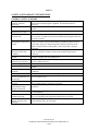
SAFETY TERMS AND SYMBOLS
CAUTION:
Caution statements identify conditions or practices that, if not avoided, can
result in personal injury and/or damage to the equipment or other property.
WARNING:
Warning statements identify conditions or practices that, if not avoided,
can result in personal injury or loss of life, and/or damage to equipment or
other property.
DANGER:
Danger statements identify conditions or practices that present an
immediate danger and, if not avoided, will result in personal injury or loss
of life.
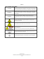
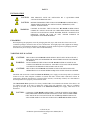
Attention symbol: Indicates important installation, operating, and/or
maintenance instructions.
Shock Hazard symbol: Indicates risk of electric shock.
Shock Hazard label.
Indicates risk of electric shock and is located on the equipment itself.
Protective Earth Ground symbol, internal: Indicates primary protective
earth ground, internal to the equipment.
System Earth Ground symbol, external: Indicates system earth ground.
© UltraVolt, Inc.
HV Rack® System Installation and Operators Manual, Rev. F
4 of 23
PART 1
ULTRAVOLT INC, BASIC WARRANTY
WARRANTY: The Seller warrants all goods supplied hereunder will conform to any sample approved
by the parties and will be the kind described herein or in any specification, performance requirement, or
drawing approved by the Seller, and will be of merchantable quality and free from defects in material or
workmanship under normal use and prescribed maintenance for a period of one (1) year from the date of
shipment. To the extent the Buyer does not furnish the Seller with written specifications, the goods will
be manufactured in accordance with industry accepted standards. This warranty shall not apply to any
goods delivered hereunder that have been damaged or subjected to alteration, nor shall it apply to
negligent treatment after delivery or to any defects attributed to artwork or drawings furnished by the
Buyer. Also, unless specifically stated, the warranty does not extend to the electrical performance of any
assemblies or subassemblies to which the goods furnished hereunder are affixed, but is restricted to the
electrical continuity properties of such goods.
The Seller’s only obligation for breach of this warranty shall be the repair or replacement, without
charge, of any goods or parts thereof that within such one (1) year period is proven to the Seller’s
satisfaction to have been defective, provided (1) the Buyer shall have notified the Seller of the defect
within such one (1) year period, and (2) the Seller shall have the option of requiring the return of the
defective material or goods at the Buyer’s expense to establish the claim provided; however, the Seller
will bear any transportation costs incurred in repairing or replacing any goods that are shown to be
defective during the warranty period. The cost of any repairs made by the Seller to goods no longer
covered by this warranty shall be borne by the Buyer. The Buyer must contact the UltraVolt Customer
Service Department prior to the return of any material(s) to obtain an RMA number which will be used to
track the material. Material found to be out of warranty will be repaired or replaced at the Seller’s
discretion based on quantity (please contact the Customer Service Department for more information). The
Seller shall in no event be liable for the Buyer's manufacturing costs, lost profits, good will, or any other
special, consequential, incidental, or other damages resulting from a breach of the foregoing warranty.
There are no other warranties expressed or implied (including the warranty of merchantability) that
extend beyond the warranty set forth herein or that extend beyond the description of the goods contained
herein.
We at UltraVolt know that when developing new high-voltage applications, power supplies may
sometimes become unintentionally damaged. We, therefore, offer an enhanced warranty beyond the scope
of our basic one-year warranty to support customers’ efforts in new-product development. Should a
power supply unintentionally fail or become damaged through incorrect application, UltraVolt will repair
or replace the first unit at no charge during the Warranty period. Then, if the same unit is unintentionally
damaged again while still within the warranty period, UltraVolt will provide another replacement at half
price. For any such replacement, UltraVolt Applications Engineering must first review the customer’s
new product application. This is done to ensure mechanical installation and electrical connections are in
accordance with UltraVolt published datasheets and application notes. The combined free replacement
and expert UltraVolt engineering review is just one of many ways UltraVolt is Making High Voltage
Easier!®
© UltraVolt, Inc.
HV Rack® System Installation and Operators Manual, Rev. F
5 of 23
PART 2
GENERAL INFORMATION
PRODUCT INFORMATION
UltraVolt’s HV Rack® power supply is a fully featured, high-performance, configurable high-voltage chassis,
providing an end user with the capability of independently controlling up to four channels of high-voltage
outputs. Each channel can be configured to control any of the more than 400 UltraVolt high-voltage power
supplies, up to 40kV and 250 watts per channel. Power can not exceed 1000 watts per channel at 6kV
maximum.
Features Include
● 1 to 4 independently configurable high-voltage output channels
● Voltage ranges from 0 to ±62VDC through ±40kV
● 4 to 1000 watts per channel, up to 1000 watts total
● Independent adjustment of each channel, through manipulation of simple front-panel controls
● Independent Voltage and Current meters for each channel
● Independent latching ‘enable’ illuminated pushbutton switch for each channel
● Preset before and during bias capability
● Constant current/Constant voltage auto-crossover
● PLC Analog/Digital Remote operation capability
● Bench top or rack-mount installation
UltraVolt’s HV Rack power supply is designed to meet numerous high-tech, high-voltage performance
requirements. It is well suited for use within a research and development laboratory environment, and may also
be used as an incoming inspection tool, for production test purposes, for new product development, for
equipment calibration, or for other engineering and manufacturing related purposes.
The Standard Convenience of the UltraVolt HV Rack power supply / UltraVolt high-voltage power supply
combination means new product development can move swiftly from prototype to market. When configuring an
HV Rack power supply, an end user can select from any of over 600 Standard UltraVolt high-voltage power
supplies. Once configured, a completely functional high-voltage power supply solution with short lead time is
available for development purpose. When the new design is proven and verified through prototype
functionality, the exact same high-voltage power supply used in the UltraVolt HV Rack power supply can be
obtained for immediate use in the new product. This makes for unparalleled Convenience for new-product
design through development to finished product.
© UltraVolt, Inc.
HV Rack® System Installation and Operators Manual, Rev. F
6 of 23
PART 3
INSTALLATION
CAUTION:
THIS PRODUCT MUST BE INSTALLED BY A QUALIFIED HIGH
VOLTAGE TECHNICIAN ONLY
CAUTION:
BEFORE ENERGIZING THE ULTRAVOLT HV RACK® POWER SUPPLY,
THOROUGHLY REVIEW ALL INSTALLATION, OPERATION, AND
SAFETY INSTRUCTIONS
WARNING:
FAILURE TO INSTALL THE ULTRAVOLT HV RACK POWER SUPPLY
CORRECTLY AND TO FOLLOW ALL OPERATING INSTRUCTIONS MAY
CREATE AN ELECTRICAL SHOCK HAZARD, WHICH CAN RESULT IN
PERSONAL INJURY OR LOSS OF LIFE, AND/OR DAMAGE TO
EQUIPMENT OR OTHER PROPERTY
UNPACKING
When unpacking the equipment, ensure all packaging materials, tapes, and cartons have been removed. All
ventilation openings in the chassis must be free of obstructions. Thoroughly inspect the equipment for damage
that may have occurred during shipment. If such damage occurred, further inspection of packaging materials
and cartons may be necessary. A claim must be filed immediately.
TABLETOP INSTALLATION
CAUTION: THE ULTRAVOLT HV RACK POWER SUPPLY MUST ONLY BE PLACED ON A
WARNING:
BENCH TOP SURFACE DESIGNED FOR AND STURDY ENOUGH TO SUPPORT
ITS WEIGHT.
DO NOT OPERATE THE ULTRAVOLT HV RACK SYSTEM ON A METAL OR
CONDUCTIVE BENCH TOP SURFACE. FAILURE TO FOLLOW THIS WARNING
CAN RESULT IN PERSONAL INJURY OR LOSS OF LIFE
CAUTION: THE ULTRAVOLT HV RACK SYSTEM MUST ONLY BE INSTALLED AND
OPERATED IN A LOCATION WHERE ADEQUATE VENTILATION IS ASSURED.
Should the end user decide to install the UltraVolt HV Rack power supply on a bench top surface, it should be
located in an area where adequate ventilation is assured and where external cable connections will not be
inadvertently disturbed, disconnected, or loosened. Place the unit, conveniently oriented, on a nonconductive
bench top surface near a properly wired electrical outlet.
The UltraVolt HV Rack system has five factory-installed rubber feet mounted to the bottom of the chassis. All
five rubber feet must be in place to support the weight of the unit adequately. Also, there are ventilation
openings on all sides, the top, and the bottom of the UltraVolt HV Rack power supply, which must not be
obstructed.
CAUTION: ULTRAVOLT’S HV RACK POWER SUPPLY CAN BE STACKED UP TO THREE
HIGH, PROVIDED THE BOTTOM MOUNTED FACTORY-INSTALLED RUBBER
FEET ARE IN PLACE. DO NOT STACK ANY OTHER EQUIPMENT OR PLACE
ANY OTHER OBJECT ON TOP OF ULTRAVOLT’S HV RACK POWER SUPPLY.
© UltraVolt, Inc.
HV Rack® System Installation and Operators Manual, Rev. F
7 of 23
RACK MOUNT INSTALLATION
CAUTION:
CAUTION:
CAUTION:
CHASSIS SLIDE RAILS ARE RECOMMENDED WHEN INSTALLING THE
ULTRAVOLT HV RACK® SYSTEM IN AN INDUSTRIAL RACK. THE HV RACK
POWER SUPPLY SHOULD NOT BE MOUNTED OR SUPPORTED BY THE FRONT
PANEL ALONE IF SUBJECTED TO HIGH VIBRATION OR SHOCK AS MIGHT
OCCUR IN A MOBILE ENVIRONMENT, OR DURING TRANSPORT.
THE SLIDE RAILS AND MOUNTING HARDWARE SHOULD BE OF A TYPE
OBTAINED THROUGH OR RECOMMENDED FOR USE BY ULTRAVOLT. USE OF
INCORRECT SLIDE RAILS OR HARDWARE CAN RESULT IN PERSONAL
INJURY AND/OR DAMAGE TO THE EQUIPMENT OR OTHER PROPERTY.
ULTRAVOLT’S HV RACK POWER SUPPLY MUST ONLY BE INSTALLED AND
OPERATED IN A LOCATION WHERE ADEQUATE VENTILATION IS ASSURED.
Should the end user decide to install the UltraVolt HV Rack power supply in an industrial 19” rack, UltraVolt
recommends using slide rails. The slide rails and mounting hardware should be of a type obtained through or
recommended for use by UltraVolt and correctly sized to support the weight of the UltraVolt HV Rack power
supply. Additionally, the screws used to attach the slide rails to either side of the HV Rack power supply must
be of the correct length to prevent contact with internal components.
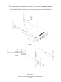
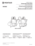
Each slide kit contains 1 pair of slides for the left and right side of the chassis. The slides are symmetrical and
individual components can be used interchangeably. Each slide kit consists of four brackets, two slide sections
(including two chassis inside sections), and hardware (figures 1, 2 and 3).
1) Fully extend each chassis slide assembly, pulling the chassis inside section (item 1) outwards until the
chassis and the intermediate sections (item 2) lock into place.
2) Remove the chassis section by grasping the slide assembly and pressing the button lock on the outside of
the chassis inside section. Pull the chassis inside section free.
3) UltraVolt’s HV Rack system is equipped with PEM nut-mounting patterns on both sides to mount the
rack slides’ chassis sections. Mount the chassis inside sections to each side of the UltraVolt HV Rack
power-supply chassis with four (4) each of the supplied 8-32x1/4 pan-head machine screws (item 10). When
doing so, ensure the button stop on the end of the chassis inside section is oriented towards the rear of the
system (figure 1).
4) Assemble the front-end brackets (item 4) to the outside of each slide (item 3) with four (4) supplied 1032x1/2 pan-head machine screws, four (4) flat washers (item 15), and four (4) 10-32 locking nuts (item 21).
Before tightening, ensure the two sections are aligned straight with one another and that the distance
between the forward end of the front bracket and the forward end of the slide measures 3.89”, as indicated
(figure 2). Tighten all hardware.
5) Install the rear-end brackets (item 4) to the outside of each slide (item 3) with four (4) supplied 10-32x1/2
pan-head machine screws, four (4) flat washers (item 15), and four (4) 10-32 locking nuts (item 21). Do not
tighten at this time.
6) Determine the height at which UltraVolt’s HV Rack system is to be positioned in the industrial rack.
Position and hold the previously assembled slide section with two attached end brackets in place, with the
right angle slotted flange towards the inside edges of the industrial rack. Slip a 10-32x1/2 screw (item 11)
through the front of the industrial rack-mounting edge and through the front slotted end flange. Secure with
a split ring locking washer (item 16) and a nut (item 20), capturing the slotted flange between the nut and
industrial rack-mounting inside edge. Repeat this for the rear bracket. Double up the fasteners on both the
front and rear mounting screws; two screws in front and two in back for each side. Tighten all hardware.
© UltraVolt, Inc.
HV Rack® System Installation and Operators Manual, Rev. F
8 of 23
7) Fully extend and lock the slide into place. With the help of an assistant, lift the UltraVolt HV Rack
power supply, aligning the chassis inside sections with the extended slide sections and slip into place. Then,
for full engagement, depress and hold the button safety locks on the inside sections and fully collapse the
slide sections, easing the UltraVolt HV Rack power supply into place.
Figure 1
Figure 2
Figure 3
© UltraVolt, Inc.
HV Rack® System Installation and Operators Manual, Rev. F
9 of 23
PART 4
ELECTRICAL CONNECTIONS
WARNING:
THIS UNIT IS EQUIPPED WITH A THREE CONDUCTOR GROUNDED
LINE CORD. THIS LINE CORD MUST BE USED WITH A PROPERLY
WIRED GROUNDED RECEPTACLE, WHERE THE GROUNDING WIRE IS
CONNECTED TO PROTECTIVE EARTH GROUND. FAILURE TO GROUND
PROPERLY CAN RESULT IN PERSONAL INJURY OR LOSS OF LIFE
AND/OR DAMAGE TO EQUIPMENT OR OTHER PROPERTY.
CAUTION:
PRIOR TO MAKING ANY ELECTRICAL CONNECTIONS TO THE
ULTRAVOLT HV RACK® POWER SUPPLY, ENSURE THE FRONT AND
REAR PANEL POWER SWITCHES ARE IN THE OFF POSITION. FAILURE
TO DO SO CAN RESULT IN PERSONAL INJURY AND/OR DAMAGE TO
THE EQUIPMENT OR OTHER PROPERTY.
CABLES AND INTERCONNECTS
Prior to making any electrical connections, ensure that the UltraVolt HV Rack system is configured as follows:
Set the front panel power switch to OFF (zero)
Set the rear panel power switch to OFF (zero)
Set the front panel controls for all channels:
Voltage Programming Dial – Set to 0
Current Programming Dial – Set to 0
Channel Enable Button, HV ON – Set to OFF (out)
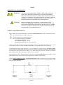
Connect external cable assemblies as required, depending upon the specific application. While doing so, ensure
correct polarity is observed. Cable assemblies should only be of a type approved for use by Ultravolt.
The standard high-voltage-return connection is a 2-way binding post, isolated from the UltraVolt HV Rack
system’s protective earth ground. High voltage return is referenced to earth ground through a 1kΩ impedance
and clamped for electrical transients exceeding +/-91V. When making this connection, UltraVolt recommends
using a ring lug rather than a banana plug to ensure a secure connection.
All external-device chassis grounds should be connected to the UltraVolt HV Rack power supply’s system
ground stud located on the rear panel using an appropriately sized and crimped ring lug.
Connect only the supplied line cord to the UltraVolt HV Rack system’s rear-panel AC power entry module.
Connect the other end to a properly rated and protected wired AC outlet. Ensure a functional protective earth
ground has been established.
© UltraVolt, Inc.
HV Rack® System Installation and Operators Manual, Rev. F
10 of 23
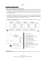
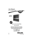
TYPICAL SYSTEM WIRING DIAGRAM
© UltraVolt, Inc.
HV Rack® System Installation and Operators Manual, Rev. F
11 of 23
PART 5
CONTROLS AND INDICATORS
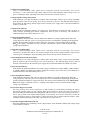
FRONT PANEL CONTROLS AND INDICATORS
UltraVolt’s HV Rack® system can provide up to 4 channels of high-voltage power. The channels are configured
at the factory to customer requirements. During operation, the output voltage and current for each channel can
be individually set and monitored either through adjustment of the front-panel controls or remotely. Each
channel also has an HV ON switch, which enables or disables the output. Voltage and current can be preset
prior to enabling the output.
In addition to the individual channel controls, there are a Front Panel AC Power Switch that will disconnect the
AC line and a remote indicator to show when the rear panel Remote Control Selector DIP Switch is in the
‘remote’ position. ‘Local’ setting enables all front-panel controls; ‘remote’ setting transfers all operation and
programming functions to the rear-panel-mounted 37-pin ‘D’ connector.
(The following front-panel diagram shows a four-channel, configured UltraVolt HV Rack power supply and
may differ from other configurations.)
1
2
3
4
5
6
7
8
9
10
11
Channel Identifier
Voltage Programming Dial
Voltage Monitor/Voltage Preset Meter
Voltage Scale Indicator
Voltage Regulation Indicator
Current Programming Dial
Current Monitor/Current Preset Meter
Current Scale Indicator
Current Regulation Indicator
Current/Voltage Preset Switch (momentary)
Channel Output Enable Switch, HV ON
(latching)
12 Front Panel AC Power Switch
1) Channel Identifier
High-voltage output channels A, B, C, and D (corresponding to rear-panel channel markings A, B, C, and D).
© UltraVolt, Inc.
HV Rack® System Installation and Operators Manual, Rev. F
12 of 23
2) Voltage Programming Dial
This is a ten-turn locking control. When used in conjunction with the Current/Voltage Preset Switch
(momentary), it varies and sets the high-voltage output for the associated channel. Output voltage can be set
prior to enabling the output, depending on the status of HV ON (HV ON switch, item 11).
3) Voltage Monitor/Voltage Preset Meter
Each channel has a 4½-digit LED display to indicate either actual output voltage or preset voltage, depending
upon the position of the Current/Voltage Preset Switch (momentary) (item 10). The indicated output voltage is
derived from the high-voltage monitor signal on the UltraVolt power supply and is scaled and calibrated to
within 1% of full scale.
4) Voltage Scale Indicator
Each channel has illuminated indicators for voltage scale. The indicators will light with either “VOLTS” or
“KILO VOLTS,” depending upon channel configuration, which is preset at the factory. The indicators are
illuminated whenever the chassis main power is on.
5) Voltage Regulation Indicator
Each channel has an indicator that, when lit, indicates the channel is in voltage regulation mode. Either the
Voltage Regulation Indicator or the Current Regulation Indicator will illuminate, depending upon output load
and upon the programmed settings for voltage and current. The status is selected automatically by the HV
Rack® power supply’s “automatic-crossover” capability. This indicator is inactive when the channel’s highvoltage output is disabled.
6) Current Programming Dial
This is a ten-turn locking control. When used in conjunction with the Current/Voltage Preset Switch
(momentary), this dial varies and sets the maximum output current for the associated channel. Output current
can be set prior to enabling the output, depending on the status of HV ON (HV ON switch, item 11).
7) Current Monitor/Current Preset Meter:
Each channel has a 4½-digit LED display to indicate either actual output current or preset current, depending
upon the position of the Current/Voltage Preset Switch (momentary). The indicated output current is derived
from the current monitor on the UltraVolt power supply and is scaled and calibrated to eliminate any offsets.
8) Current Scale Indicator
Each channel has illuminated indicators for current scaling. The indicators will light “AMPS,” “MILLI AMPS,”
or “MICRO AMPS,” depending upon channel configuration, which is preset at the factory. The indicators are
illuminated whenever the chassis main power is on.
9) Current Regulation Indicator
Each channel has an indicator that, when lit, indicates the channel is in current regulation mode. Either the
Voltage Regulation Indicator or the Current Regulation Indicator will illuminate, depending upon output load
and the programmed settings for voltage and current. The status is selected automatically by the UltraVolt HV
Rack power supply’s “automatic-crossover” capability. This indicator is inactive when the channel’s highvoltage output is disabled.
10) Current/Voltage Preset Switch
The Current/Voltage Preset Switch (momentary) is used to display or to both display and change the voltage
and current program settings for each channel. When pressed and held, voltage and current set points are
displayed. When pressed and held while manipulating either the Voltage or Current Programming Dial (items 2
and 6), the set points can be adjusted. Releasing the Current/Voltage Preset Switch (momentary) returns the
voltage and current meters to output monitor. Voltage and current can be adjusted when the output is either
enabled or disabled, depending on the status of HV ON (HV ON switch, item 11).
11) Channel Output Enable Switch, HV ON
When the pushbutton HV ON (latching) switch is depressed, the switch illuminates and the high-voltage output
for that channel is enabled.
© UltraVolt, Inc.
HV Rack® System Installation and Operators Manual, Rev. F
13 of 23
12) Front Panel AC Power Switch
This is the front-panel AC power switch (there is a Rear Panel Main AC Power Switch as well). This switch
must be “ON” (On = 1) for the UltraVolt HV Rack® power supply to be functional. (Both rear- and front-panel
AC switches must be on).
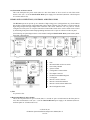
REAR PANEL CONNECTIONS, CONTROLS AND INDICATORS
The HV Rack system can provide up to 4 channels of high-voltage power (configurations vary). Each channel
has an inline cooling fan and a configurable high-voltage-output connector plate. The plate is used to mount the
high-voltage-output and high-voltage-return connectors. The actual connectors can vary and are custom
configured for each system. A rear-panel remote/local control DIP switch can be used to enable remote control
by transferring front-panel control and programming functions to the 37-pin ‘D’ connector on the rear panel.
(The following rear-panel diagram shows a four-channel configured UltraVolt HV Rack system and may differ
from other configurations.)
1
2
3
4
5
6
7
8
9
10
11
12
Fuse
Rear Panel Main AC Power Switch
Power Entry Module
System Ground
Configurable Connector Plate
HV Output Connector
HV Return Ground Binding Post
Cooling Fan
Remote Control Connector
Remote Control LED indicator
Remote Control Selector DIP Switch
Rack Configuration Label
1) Fuse
AC protective fuse
2) Rear Panel Main AC Power Switch
This is the rear-panel main AC power switch (there is a second AC power switch located on the front panel as
well). This switch must be “ON” (On = 1) for the UltraVolt HV Rack power supply to be functional (both rearand front-panel AC switches must be on).
© UltraVolt, Inc.
HV Rack® System Installation and Operators Manual, Rev. F
14 of 23
3) Power Entry Module
The HV Rack system is equipped with a filtered power-entry module, IEC 320/C20 inlet.
4) System Ground
The UltraVolt HV Rack system is equipped with a ¼” x 20-thread, ½”-long, 18-8, stainless-steel ground stud.
This is used for connecting the HV Rack power supply’s chassis to system ground.
5) Configurable Connector Plate
UltraVolt’s HV Rack power supply is equipped with a configurable output plate for each channel. Each plate is
custom configured based upon customer requirement and consists of a high-voltage connector and high-voltage
return for each channel. Both connectors are isolated from chassis ground.
6) HV Output Connector
The standard high-voltage connector is an Alden B110YX, rated 40kV (other connectors are available). This
connector is internally wired to the UltraVolt high-voltage-power-supply output for the indicated channel.
7) HV Return Ground Binding Post
The standard high-voltage return is a 2-way binding post, isolated from chassis ground. This connector is
internally wired to the UltraVolt high-voltage-power-supply return for the indicated channel. High voltage
return is referenced to earth ground through a 1kΩ impedance and clamped for electrical transients exceeding
+/-91V. UltraVolt recommends using a ring lug to secure the HV return so it cannot inadvertently become
disconnected.
8) Cooling Fan
The HV Rack power supply has four cooling fans mounted on the rear panel. Air is drawn in from the back and
is blown through the equipment.
9) Remote Control Connector
The UltraVolt HV Rack system is equipped with remote control capability via a rear-panel, 37-pin ‘D’ female
connector (Metal shell connected to the chassis). The Remote/Local Selector DIP Switch, when correctly set,
enables remote control. Active remote control is indicated by a green status LED on the rear panel (and by a
remote indicator on the front panel). Through remote control connection, each of up to four channels’ signals
can be individually controlled and monitored including the following: output enable, voltage programming,
current programming, voltage monitor, and current monitor. In addition, there is a ‘global output enable’ signal,
which will enable/disable all channels simultaneously.
10) Remote Control LED indicator
This indicator illuminates when remote control is enabled.
11) Remote Control Selector Switch
When correctly set; this switch enables remote control of the UltraVolt HV Rack power supply. Switch 2 ON
(on = 1), enables remote control. Switch 2 OFF (off = 0) disables remote control. Switch 1 is not currently used.
12) Rack Configuration Label
This label indicates which model of UltraVolt high-voltage power supply is installed in each channel of this
UltraVolt HV Rack system.
© UltraVolt, Inc.
HV Rack® System Installation and Operators Manual, Rev. F
15 of 23
PART 6
OPERATION
WARNING:
PRIOR TO APPLYING POWER TO THE SYSTEM, ENSURE ALL
CONNECTIONS ARE PROPERLY TERMINATED. FAILURE TO WIRE
CORRECTLY CAN RESULT IN PERSONAL INJURY OR LOSS OF LIFE,
AND/OR DAMAGE TO EQUIPMENT OR OTHER PROPERTY.
OPERATION USING FRONT PANEL CONTROLS
Prior to powering on the HV Rack® power supply, ensure the front panel controls for each channel are set as
follows:
Voltage Programming Dial – Set to 0
Current Programming Dial – Set to 0
Channel Output Enable HV ON – Set to OFF (off = out)
The UltraVolt HV Rack system has two AC power switches: one located on the rear panel and one located on
the front panel. Both must be ON (on = 1) to enable the internal power supply.
Apply AC power by individually toggling both the front- and rear-panel AC power switches to the ON position.
No high-voltage output should be present on any channel at this time, and the HV ON latching switch should not
be lit. ‘Power on’ will be indicated by the illumination of both the Voltage Monitor/Voltage Preset Meter and
the Current Monitor/Current Preset Meter for all channels. Each display will typically read 0000 (null).
Additionally the Voltage Scale Indicator will light with either “VOLTS” or “KILO VOLTS,” and the Current
Scale Indicator will light with any of “AMPS,” “MILLI AMPS,” or “MICRO AMPS” (ranges are factory
preset).
Select a channel to work with, then press and hold the Current/Voltage Preset Switch (momentary). Adjust the
Voltage Programming Dial until the desired voltage is obtained, as displayed on the Voltage Monitor/Voltage
Preset Meter. While still holding the Current/Voltage Preset Switch, adjust the Current Programming Dial until
the desired current is obtained, as displayed on the Current Monitor/Current Preset Meter. Release the switch;
voltage and current values have now been programmed into the UltraVolt HV Rack system for that channel.
DANGER:
PRESSING THE HV ON SWITCH AT THIS TIME WILL ACTIVATE AND
ENABLE THE HIGH-VOLTAGE OUTPUT FOR THAT CHANNEL. FAILURE
TO ADHERE TO ANY PREVIOUS INSTALLATION OR OPERATING
INSTRUCTIONS – OR IN ANY WAY ACTING IN AN UNSAFE MANNER
WHILE AROUND THE EQUIPMENT – CAN PRESENT AN IMMEDIATE
DANGER, WHICH IF NOT AVOIDED CAN RESULT IN PERSONAL INJURY
OR LOSS OF LIFE.
Press and release the HV ON pushbutton switch for the desired channel. The switch will latch recessed into
place and illuminate. The high-voltage output for that channel will now be active and enabled. The Voltage
Monitor/Voltage Preset Meter will display the actual output voltage, and the Current Monitor/Current Preset
Meter will display the actual output current.
Either the Voltage Regulation Indicator or the Current Regulation Indicator will be illuminated. The status is
dependent upon output load and voltage/current preset settings and is automatically determined by the HV Rack
power supply’s ‘automatic-crossover’ feature.
Each output can be adjusted in real time simply by manipulating the respective channel’s Voltage Programming
Dial or Current Programming Dial. Alternatively, each output can be preset using the Voltage Programming
Dial or Current Programming Dial in conjunction with the Current/Voltage Preset Switch. The voltage and
current meters will display the actual values as they change.
© UltraVolt, Inc.
HV Rack® System Installation and Operators Manual, Rev. F
16 of 23
OPERATION USING REMOTE CONTROL
WARNING:
ENABLING REMOTE CONTROL DISABLES FRONT-PANEL CHANNEL
CONTROLS: HV ON, VOLTAGE PROGRAMMING DIAL, CURRENT
PROGRAMMING DIAL, VOLTAGE/CURRENT PRESET SWITCH. PRIOR TO
APPLYING AC POWER TO THE HV RACK POWER SUPPLY, ENSURE THE
EXTERNAL CONTROLLER IS FUNCTIONING AND COMMUNICATING
PROPERLY WITH THE HV RACK POWER SUPPLY AND IT IS IN A
KNOWN STATE OF OPERATION AND CONTROL. FAILURE TO DO SO
MAY CREATE A CONDITION THAT CAN RESULT IN PERSONAL INJURY
OR LOSS OF LIFE AND/OR DAMAGE TO EQUIPMENT OR OTHER
PROPERTY.
All functions of the UltraVolt HV Rack® power supply can be controlled remotely through use of the 37-pin
Remote Control Connector mounted on the rear panel. Remote control is enabled by setting the Remote Control
Selector DIP Switch (see rear-panel figure for the location of the DIP switch). To enable, set the rear-panel DIP
switch 2 to ON (on = 1) prior to applying AC power. When remote is enabled, the status indicator, ‘remote,’
located on the upper right-hand corner of the front panel will illuminate.
Appendix B of this manual describes the I/O control and status signals accessible on each pin of the 37-pin
connector. It is the responsibility of the end user to wire the interface connector correctly and, importantly, to
understand the functionality of each I/O control and status signal as it applies to the operation and use of the
UltraVolt HV Rack system in its intended application. The end user is encouraged to consult with an UltraVolt
Customer Service Department Applications Engineer. The following is a description of the I/O control and
status signals available for each channel:
Remote Enable A {B/C/D}: This is a digital input signal, TTL level, that when asserted True (+5VDC)
enables the high voltage output. It performs the same function as the front-panel switch, HV ON. When a
channel is remotely enabled, the Channel Output Enable Switch, HV ON for that channel will illuminate.
Output voltage and current can be programmed prior to enabling the high-voltage output remotely. Once
the high-voltage channel has been enabled, either the Voltage Regulation Indicator or Current
Regulation Indicator will illuminate on the front panel. Which indicator is illuminated is dependent upon
output load and voltage/current preset settings and is automatically determined by the UltraVolt HV
Rack system’s ‘automatic-crossover’ feature.
Remote Voltage Adj A {B/C/D}: This is an analog input signal and is used to adjust the high-voltage output
voltage. A DC voltage can be applied within the range of 0VDC thru 5VDC, representing a high-voltage
output swing of 0% Vout thru 108% Vout with 4.64VDC input equal to 100% Vout. The HV Rack power
supply’s front-panel Voltage Monitor/Voltage Preset Meter and the Voltage Scale Indicator will display
the actual voltage.
Remote Current Adj A {B/C/D}: This is an analog input signal and is used to adjust the high-voltage output
current. A DC voltage can be applied within the range of 0VDC thru 5VDC, representing an output
current swing of 0% Iout thru 108% Iout, with 4.64VDC input equal to 100% Iout. The UltraVolt HV Rack
system’s front-panel Current Monitor/Current Preset Meter and Current Scale Indicator will display the
actual current.
Remote Voltage Monitor A {B/C/D}: This is a scaled analog output signal and can be used to monitor the
high-voltage output voltage remotely. The signal’s range is 0VDC thru 5VDC, representing an output
voltage swing of 0% Vout thru 108% Vout with 4.64VDC output equal to 100% Vout.
Remote Current Monitor A {B/C/D}: This is a scaled analog output signal and can be used to monitor the
high-voltage output current remotely. The signal’s range is 0VDC thru 5VDC, representing an output
current swing of 0% Iout thru 108% Iout with 4.64VDC output equal to 100% Iout.
© UltraVolt, Inc.
HV Rack® System Installation and Operators Manual, Rev. F
17 of 23
Reference Voltage A {B/C/D}: This is a 5VDC precision output reference and can be used as a source voltage
to control the Remote Voltage Adj A {B/C/D} and the Remote Current Adj A {B/C/D} remote-input
signals.
Signal Ground A {B/C/D}: This is signal return ground for Channel A {B/C/D}.
In addition to individual channel I/O control and status signals, there is a Global Disable signal:
Global Disable {channels A, B, C, and D}: This is a digital input signal, TTL level, that when asserted True
(+5VDC) disables all high-voltage outputs; when asserted False (0VDC), it enables all high-voltage
outputs.
A +15VDC, 100mA power tap and return is also available on the remote connector. It can be used to power
external circuitry.
© UltraVolt, Inc.
HV Rack® System Installation and Operators Manual, Rev. F
18 of 23
PART 7
MAINTENANCE AND CALIBRATION
WARNING:
ATTEMPTING TO REPAIR, MODIFY, OR IN ANY WAY TAMPERING WITH THE
ULTRAVOLT HV RACK® POWER SUPPLY WILL VOID THE WARRANTY AND
CAN CREATE A DANGEROUS CONDITION WHICH CAN RESULT IN
PERSONAL INJURY AND/OR DAMAGE TO EQUIPMENT OR OTHER PROPERTY
MAINTENANCE
The UltraVolt HV Rack system is designed for years of reliable operation. Under normal operating conditions,
it should not require any maintenance except for occasional external cleaning. If any question should arise,
contact UltraVolt’s Customer Service Department to speak with an Applications Engineer.
ROUTINE CLEANING
All ventilation openings – top, bottom, sides, and rear panel – should be checked periodically and kept free of
dust and other obstructions. A vacuum may be used to clean these vents when the unit is powered off. Do not
use compressed air to clear the vents.
The front panel may be cleaned periodically with a lint-free cloth and mild isopropyl alcohol solution, when the
unit is powered off.
CALIBRATION
Under normal operating conditions, the UltraVolt HV Rack power supply should not require calibration.
However, it can be returned to the factory for complete electrical and mechanical inspection. Also, if required,
an NIST certificate can be issued for traceability. Contact UltraVolt’s Customer Service Department for
additional information.
© UltraVolt, Inc.
HV Rack® System Installation and Operators Manual, Rev. F
19 of 23
APPENDIX A
SPECIFICATIONS
CAUTION:
ALL SPECIFICATIONS ARE SUBJECT TO CHANGE WITHOUT NOTICE.
CUSTOMERS ARE NOT NOTIFIED WHEN CHANGES OCCUR UNLESS THEY
HAVE ARRANGED FOR CONFIGURATION CONTROL WITH ULTRAVOLT’S
CUSTOMER SERVICE DEPARTMENT (“CSD”) THROUGH THE “-Q” SUFFIX
PROGRAM. ONLY THOSE ITEMS OF GREATEST SIGNIFICANCE WILL BE
POSTED ON ULTRAVOLT’S WEB SITE, IN THE PRODUCT-CHANGE NOTICE
SECTION.
Since each channel of the UltraVolt HV Rack® system is custom configured with a specific model of UltraVolt®
high-voltage power supply, the end user should refer to UltraVolt’s datasheet for the electrical specifications of that
model.
Storage Temperature
Storage temperature range is -40C° to +85C°.
Operating Altitude, Humidity & Temperature:
UltraVolt HV Rack Series operating performance is guaranteed between sea level and 10,000ft in noncondensing relative humidity up to 95% between temperatures of +10°C and +45°C.
Shock and vibration
TBD
AC Power
The AC operating voltage and power rating is system configuration dependant as indicated in the following
table:
System configuration
X-250
X-500
X-750
X-1000
Voltage
115/230 VAC
115/230 VAC
230 VAC
230 VAC
Max rating power
375W
750W
1125W
1500W
Frequency
50/60Hz
50/60Hz
50/60Hz
50/60Hz
Fuse
T8A 250VAC
T8A 250VAC
T8A 250VAC
T8A 250VAC
Fuse
AC power is fused through a 5mm x 20mm, time-delay fuse located on the rear panel. The fuse must always be
replaced with the same type and rating, as per the UltraVolt HV Rack power supply rating label.
HV connectors
The UltraVolt HV Rack system is equipped with a configurable output plate for each high-voltage output
channel. Each rack can have custom-configured high-voltage output and return connectors, according to
customer requirement. The basic UltraVolt HV Rack system includes Alden B110YX 40kV industrial highvoltage output connectors and a two-way binding post return for each channel.
Package
Chassis dimensions: 17.00” wide x 18.50” deep x 5.00” high (431,8 x 469,9 x 127,0mm). Width is measured
chassis side to opposite side; depth is measured from the back of the front-panel mounting flange to chassis
rear and does not include rear-panel connector protrusion; height is measured chassis top to chassis bottom
and does not include the height of rubber feet mounted on the bottom.
© UltraVolt, Inc.
HV Rack® System Installation and Operators Manual, Rev. F
20 of 23
Front-panel dimensions: 19.00” wide x 0.125” deep x 5.25” high (3U) (482,60 x 3,18 x 133,35mm). These
measurements do not include handles or controls. Front-panel mounting holes are configured for both #10-32
and M6 rack configurations.
Weight: Approximately 30 pounds (11,2kg), configuration dependent; approximately 40 pounds (14,93kg)
shipping.
© UltraVolt, Inc.
HV Rack® System Installation and Operators Manual, Rev. F
21 of 23
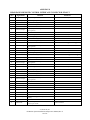
APPENDIX B
REAR PANEL REMOTE CONTROL INTERFACE CONNECTOR PINOUT
Pin
Number
Signal Name
Function
Parameter
1
Remote Enable A
Input, TTL high to enable, low to disable Channel A
Default is disable via internal pull down
2
Remote Voltage Adj A
Input, Voltage Programming for Channel A
0V to 4.64V = 0V to 100% Vout (5V = 108% Vout)
3
Voltage Monitor A
Output, Scaled Voltage Monitor for Channel A
0V to 4.64V = 0Vout to 100% Vout (5V = 108% Vout)
4
Remote Current Adj A
Input, Current Programming for Channel A
0V to 4.64V = 0A to 100% Iout (5V = 108% Iout)
5
Current Monitor A
Output, Current Monitor for Channel A
0V to 4.64V = 0A to 100% Iout (5V = 108% Iout)
6
Reference Voltage A
Output, 5V precision voltage reference returned to
signal ground A
7
Signal Ground A
Signal Ground for Channel A
8
Remote Enable B
Input, TTL high to enable, low to disable Channel B
Default is disable via internal pull down
9
Remote Voltage Adj B
Input, Voltage Programming for Channel B
0V to 4.64V = 0V to 100% Vout. (5V = 108% Vout)
10
Voltage Monitor B
Output, Scaled Voltage Monitor for Channel B
0V to 4.64V = 0Vout to 100% Vout (5V = 108% Vout)
11
Remote Current Adj B
Input, Current Programming for Channel B
0V to 4.64V = 0A to 100% Iout (5V = 108% Iout)
12
Current Monitor B
Output, Current Monitor for Channel B
0V to 4.64V = 0A to 100% Iout (5V = 108% Iout)
13
Reference Voltage B
Output, 5V precision voltage reference returned to
signal ground B
14
Signal Ground B
Signal Ground for Channel B
15
Remote Enable C
Input, TTL high to enable, low to disable Channel C
Default is disable via internal pull down
16
Remote Voltage Adj C
Input, Voltage Programming for Channel C
0V to 4.64V = 0V to 100% Vout. (5V = 108% Vout)
17
Voltage Monitor C
Output, Scaled Voltage Monitor for Channel C
0V to 4.64V = 0Vo to 100% Vout (5V = 108% Vout)
18
Remote Current Adj C
Input, Current Programming for Channel C
0V to 4.64V = 0A to 100% Iout (5V = 108% Iout)
19
Current Monitor C
Output, Current Monitor for Channel C
0V to 4.64V = 0A to 100% Iout (5V = 108% Iout)
20
Reference Voltage C
Output, 5V precision voltage reference returned to
signal ground C
21
Signal Ground C
Signal Ground for Channel C
22
Remote Enable D
Input, TTL high to enable, low to disable Channel D
Default is disable via internal pull down
23
Remote Voltage Adj D
Input, Voltage Programming for Channel D
0V to 4.64V = 0V to 100% Vout. (5V = 108% Vout)
24
Voltage Monitor D
Output, Scaled Voltage Monitor for Channel D
0V to 4.64V = 0Vout to 100% Vout (5V = 108% Vout)
25
Remote Current Adj D
Input, Current Programming for Channel D
0V to 4.64V = 0A to 100% Iout (5V = 108% Iout)
26
Current Monitor D
Output, Current Monitor for Channel D
0V to 4.64V = 0A to 100% Iout (5V = 108% Iout)
27
Reference Voltage D
Output, 5V precision voltage reference returned to
signal ground D
28
Signal Ground D
Signal Ground for Channel D
29
Not Used
30
Not Used
31
Not Used
32
Not Used
33
Not Used
34
Not Used
35
+15V, 100mA power
Output, Power supply for low power external
circuitry
36
Power Ground
Return for +15V
37
Global Disable
Input, TTL signal disables all Channels, low to
enable, high to disable.
Default is ENABLE.
© UltraVolt, Inc.
HV Rack® System Installation and Operators Manual, Rev. F
22 of 23
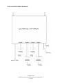
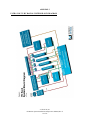
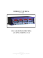
APPENDIX C
ULTRAVOLT’S HV RACK® SYSTEM BLOCK DIAGRAM
© UltraVolt, Inc.
HV Rack® System Installation and Operators Manual, Rev. F
23 of 23