1
Medallion Brand
Premium Bagger Gauges ®
TM
Operation Guide
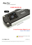
LCD Symbol Description
START GEAR LEARNING MODE - Read below for specific instructions
Current Gear Position Display
It does not matter if you have a 5-speed or 6-speed. If
the ECU does not broadcast gear information, the gauge
can be trained quickly to learn which gear you are in. If
the ECU does broadcast the information, the gauge is
ready to use.
[See the Setup Menu Below.]
GAUGE INFO - This menu displays the software version and build date of the gauge.
DIAGNOSTICS - This is the factory menu for diagnosing problems in the
Low Fuel Icon
Factory programmed to display when the fuel level
reaches 20%.
Low Battery Icon
EXIT - Pressing the RIGHT button will cause the gauge to save any changes and then
Cruise Control Icon
ENGAGED
your gauge can be restored to the original factory settings by highlighting RESTORE
DEFAULTS and pressing the RIGHT button .
instrumentation system. The first page shows the raw values that the microprocessor is
looking at. Additional pages are entered by pressing either button. On the second page is
the gauge values being sent to the gauges. The third page displays if the gauge is seeing
any data on the serial data bus from the engine.
The battery icon is displayed when the battery voltage to
the tachometer reaches 12.4 VDC with the engine running
and 12.1 VDC when the engine is not running.
ON
RESTORE DEFAULTS - If something is misadjusted or programmed incorrectly,
Is displayed when cruise is turned on. The little arrow on
the upper left side of the icon is present when cruise is
engaged.
LCD Display Mode Clock, ODOmeter, Trip A, Trip B, SERVice alarm
Bike Odometer [See Setting Odometer Below.]
reset gauge.
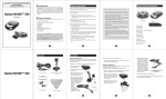
START GEAR LEARN MODE - INSTRUCTIONS
If your ECU does not broadcast the current gear, you can program the
gauge to display which gear you are in. Select this mode by pressing the
RIGHT button.
START - Begin driving down the road at a steady speed in 1st gear
(need to hold +/- 2 MPH).
Trip A is resettable and independent from Trip B. While Trip A is
displayed, pressing the right button resets TRIP A odo. While Trip B is
displayed, pressing the right button resets TRIP B odo.
Service reminder. This can be set to any mileage. Default from the
factory is 500 miles. Pressing and holding the right button allows
adjustments.
12 or 24 hour clock available. Setting the clock (LCD Display), press
and hold the right button until “12-HOUR” appears. The left button
adjusts value, the right button selects the next mode. If no buttons are
pressed in five seconds, the new clock setting will be stored.
START LEARN MODE
PRESS EITHER BUTTON AT
ANY TIME TO EXIT LEARNING MORE
LEARNING - Once the gauge has learned the gear, it will display
SAVED. You must then Shift to the next gear
LEARNING next gear - Continue driving down the road at a
steady speed (need to hold +/- 2 MPH). Until the SAVED appears. Continue
through all of the bike gears. If you need to stop or exit this mode press
either button.
SHIFT
BIKE
GEAR
UP
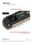
Setup Menu
To enter the SETUP menu, push and hold both buttons until the LCD displays the word
SETUP. The right button changes the option highlighted, the left button scrolls down to
the next option
PRESS BOTH
AT SAME TIME
Note: Odometer programming must be completed
within the first 100 miles after installing
1) Power up the gauges.
2) Hold both buttons for about 2.5 seconds until the LCD displays "SETUP" and the setup
SCROLL DOWN
CHANGE VALUE
menu is displayed.
3) Press the LEFT ('NEXT') button to scroll down the menu items until "SET ODOMETER" is
highlighted, then press the RIGHT ('SELECT') button.
4) One of three possible messages will now be displayed:
a) If One Time Programable [OTP] odometer has not been set and less than 100mi
have accumulated,since installing the gauges the LCD will display "Odometer can be set
FACTORY DEFAULTS
*Bike 2008 or newer
Start Gear Learn Mode
*Units: English
Set Odo
*AutoDim: Enabled
*Restore Defaults –
*Shift Icon: Flash
*Gear Source: ECU
*Demo Mode: Disabled
Set Shift Icon RPM: 3000RPM
(Note: this item is not reset with the factory reset function)
(Note: only lines with * will be restored to factory settings)
Tach Info
Fault Codes
Diagnostics
Exit
ONCE in first 100mi." Pressing the LEFT ('CONTINUE') button continues to step #5.
Pressing the RIGHT ('CANCEL') button returns to the setup menu.
b) If OTP odometer has already been set, the LCD will display "Odometer has already
been set once. Press a button to return to the setup menu." Pressing either button returns to
the setup menu.
c) If 100mi has accumulated without setting the OTP odometer, the LCD will display
"Odometer set ability has expired. Press a button to return to the setup menu." Pressing
BIKE - This will adjust the gauge system to operate with the correct fuel tables and other
features that are model year dependent.
UNITS - This changes between English and Metric units displayed on the LCD
AUTO DIM - Auto Dim turns the daylight sensor on or off enabling the LCD display and
icons to dim down at night.
SHIFT ICON - The Shift icon is an up arrow that lights up when engine RPM reaches
it’s set point. This shift point is programmable.[See Setting Odometer Below.] This shift icon
can be set to “flash” or “solid”.
GEAR SOURCE - This tells the gauge where to get the gear position. On some bikes
the 6th gear is not broadcast. Changing to “gauge” and going through the learn mode will
enable gear position. NOTE: gear position is only displayed while engaged in a gear.
either button returns to the setup menu.
5) The LCD now displays the current odometer value as "ODOMETER: xxxxxxmi" or
"ODOMETER: xxxxxxkm" depending on units. Button presses are as follows:
a) Pressing the left ('DEC') button decrements by 1 mi/km.
b) Pressing the right ('INC') button increments by 1 mi/km.
c) Holding either button decrements/increments by 1 mi/km until the odometer is
divisible by 10, then by 10 mi/km until the odometer is divisible by 100, then by 100 mi/km
until the odometer is divisible by 1000, then by 1000 mi/km thereafter.
d) When desired odometer value is displayed, holding both buttons ('<- SAVE ->') for
about 2.5 seconds saves the odometer value and returns to the setup menu.
NOTE: Once the odometer has been saved, no additional programming can be performed
and the odometer value is permanently stored.
DEMO MODE - This mode is for table top demonstration only. This mode can be
enabled, but will NOT operate if the Handlebar Control Module is connected. In this mode the
gauges will move through the gears and display icons
SET SHIFT ICON RPM - The shift icon can be setup to light at any RPM. This is
adjusted by 50 RPM steps. Press the RIGHT button to adjust up, and the LEFT button to
adjust the RPM value down. Do not press any buttons for 5 seconds to save settings.
Date: 6800-09506-01REVB
Technical Support Contact Information:
Technical Support | 616.847.3700 | [email protected]
© Medallion Instrumentation Systems LLC, Spring Lake Michigan, USA
Harley-Davidson ®, Street Glide®, and Road Glide® are registered
trademarks of Harley-Davidson Motor Company, Milwaukee, Wisconsin, USA
Medallion Brand
Premium Bagger Gauges ®
TM
Installation Instructions
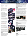
We recommend a second person to assist with fairing
disassembly and reassembly. Fender and tank covers are
recommended to help avoid accidental damage.
Step 5 [cont’d]:
Insert the gauge into the fairing opening aligning the rib on the gauge
with the notch in opening.
Hold the gauge in place with one hand while installing the bracket and
nuts provided. Tighten the nuts to secure the gauge snugly in the
fairing, but do not over tighten. Make sure the red covers are on the
end on the threaded studs.
On Road Glide FLT type fairings, install the speedometer and
tachometer into the pod and make sure the gauges are aligned and
straight to your liking before reassembly.
Common tools and supplies needed:
• T27 Torx® driver
• Wire cutters
• #2 Phillips screwdriver
• Wire crimpers
• 5/16” nut driver
• Wire ties
• 1” open-end wrench
• Electrician’s tape
• Hex wrench set
Step 6:
Step 1:
Record the mileage on the existing gauge.
Remove the inner fairing screws.
TIP: Sometimes these are hard to find. FLT Road
Glide® fairings have 6, FLH Street Glide® Fairings
have 4.
Protect the fender & tank with a cover before
you begin disassembly to avoid accidental
damage!
Step 2:
Screws
1
TIP: This is where having a second person to hold
the outer fairing would be helpful.
Disconnect
On FLH fairings, loosen the windscreen
screws and only remove the outer two
screws. Leave the middle screw in place but
loose. Remove the windscreen by wiggling
gently and set it aside. Hang onto the outer
fairing while removing the middle screw and
trim. Unplug the headlamp connector and
set the fairing aside.
On Road Glide FLT type fairing the
windscreen doesn’t need to be removed to
disassemble the fairing, but it will be easier
to reassemble the fairing without it. It can
also prevent damaging the black decal on
the windscreen during reassembly. Begin by
remove the turn signals from each side of
the fairing. Lift the outer fairing off the inner
and disconnect the headlight and set the
outer fairing aside.
2a
2b
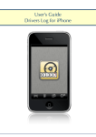
Step 8:
Disconnect
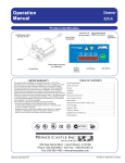
Step 4:
TIP: Its easier to put the wire harness on as you
insert each gauge. See step 6 for details.
Replace each large gauge one at a time. Place
one hand on the front of the gauge and remove
the two bracket nuts on the back of the gauge.
Push the gauge out and remove the bracket.
Position the rubber gasket on the replacement
gauge and align the notch with the
corresponding rib on the gauge housing.
Black plug
Install the oil temperature sensor into the engine oil pan by removing
the center accessory plug and replacing it with the sensor provided.
[To avoid personal injury, installation of the sensor should only
be done when the engine is cold.]
3
TIP: Its easier to put the wire harness on as you
insert each gauge. See step 6 for details.
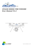
7b
Control module
If you are installing on a 2004-2006 bike, the GREEN/RED STRIPE wire
must be crimped onto the wire of the same color in the factory harness
for the CURISE ON icon. This wire can be found on the gray connector
removed from the factory tachometer. Place the splice around the
factory wire and insert the Green/Red Medallion harness wire into it.
Close the splice and crimp with pliers to complete the splice connection.
Start by removing the connectors from the
back of each gauge. It is easier to remove
the top two smaller gauges first in order to
have room to access the two lower ones.
You might have to cut some wire ties in
order to move the harness and connectors
around. DO NOT REMOVE the factory
harness. It will remain on the fairing.
Step 5:
Step 7:
Install the transition wire harness by inserting the large 12-pin plug
into the matching connector on the back of the tachometer. Install
the smaller 12-pin connector onto the black plug that was pulled out
of the factory speedometer. The 4-pin and the 8-pin on the other end
are installed into the Control Module. Insert the ¼” male blades into
the sockets of the factory oil pressure gauge plug. Make sure the
black and brown wires are matched to the same color on the
connector. Add tape to secure it in place.
On Road Glide FLT type fairings, route the end of the main harness
with the two 12-pin connectors through the wire passage tunnel.
Insert the larger connector into the tachometer and insert the black
plug removed from the factory speedometer in the smaller one.
Route the end of the gauge harness with only the two 4-pin
connectors in the same way and insert them into the tachometer and
speedometer. Pull back on the harnesses inside the fairing to make
room during pod reassembly.
7a
Step 3:
Replace each small gauge one at a time and
start with the lower two. Place one hand on
the front of the gauge and remove the two
bracket nuts on the back of the gauge. Push
the gauge out and remove the bracket. Slide
the rubber gauge retainer sleeve onto the
replacement gauge aligning the rib on the
gauge with the mating notch. Insert the gauge
& retainer assembly into the fairing opening
wiggling it into place until the rubber lip pops
out on the back side of the fairing. A soapy
solution on the leading edge of the rubber will
help the rubber retainer slip into place. Make
sure the ribs on the rubber retainer are in the
notches on the fairing opening and the
retaining lip is out all the way around the back
of the fairing. Make sure the red covers are on
the ends of the threaded studs.
Install the gauge wire harness (The harness with six 4-Pin Plugs)
by inserting the 4-pin gauge plugs into each mating connector on
the gauges. Any plug can go into any gauge, just install it in logical
order to get the wire harness to fit. Push on the front of the gauge
while installing the connector so it stays in place. Make sure
nothing is pushing on the back of the gauge when finished.
TIP: Draining the engine oil before installing the sensor is recommended to
avoid oil spills.
Remove the accessory plug [8a] and replace it with the sensor [8b].
Don’t forget to check the oil level once the sensor is
installed.
Route the temperature sensor wire harness up the frame and into the
fairing. Secure the wire harness with wire ties as necessary. Crimp
the two splices from the oil temperature harness onto the matching
stripped wire colors located on the transition harness.
4a
8b
8a
4c
Sensor replaces plug
Remove this plug
Step 9:
Retaining Lip
4b
Dress and secure the control module (HCM) and any wires to keep
them from rattling and to protect them from sharp edges.
TIP: Use electrician’s tape to protect the wire as needed.
Step 10:
Retaining Lip
Rubber Gauge Retainer
TIP: Have a second person help
Power up the gauges and verify they are working before you
reassemble the fairing.
Reassemble the fairing in the reverse order of how you disassembled it.
Step 11:
Follow the Operation Manual for set up and learning procedures.