1
DELL POWEREDGE M620 BLADE SERVER SOLUTIONS
FOR VIRTUAL DESKTOP INFRASTRUCTURES
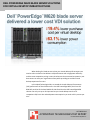
When looking for blade servers to host your virtual desktop infrastructure you
need to select a solution that delivers solid performance with a high power efficiency
and the most competitive pricing. Lower-priced servers that consume less power in your
data center can save your organization money while providing an excellent virtual
desktop experience for users.
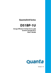
In Principled Technologies labs, we tested the virtual desktop infrastructure
(VDI) performance of three blade servers: the Dell PowerEdge M620, the Cisco UCS
B200 M3, and the HP ProLiant BL460c G8. We found that the Dell PowerEdge M620
solution not only cost up to 19.4 percent less per virtual desktop user than its
competitors did, but it also reduced power consumption by as much as 63.1 percent per
user.
OCTOBER 2012
A PRINCIPLED TECHNOLOGIES TEST REPORT
Commissioned by Dell Inc.
GETTING MORE VALUE FOR YOUR VDI
Assessing the potential of a server to deliver a seamless VDI experience to a
large number of end users is vital to planning your virtual desktop infrastructure, but
why not save money in the process?
We compared three servers with identical processors and RAM amounts—the
Dell PowerEdge M620, HP ProLiant BL460c G8, and Cisco UCS B200 M3—and used the
Login VSI 3.6 benchmark to determine that each was able to support 160 VMware View
5.1 virtual desktops. Because the servers supported the same number of virtual
desktops, we assessed the value that the servers provided along with their blade
enclosures, both in initial hardware cost and in idle and active power consumption. For
detailed server and configuration information, see Appendix A and Appendix B. For
detailed steps on how we tested, see Appendix C.
Lower cost per/user and power/user
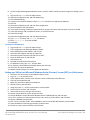
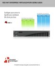
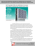
Figure 1 compares the cost per virtual desktop user, in US dollars, for the three
blade solutions. The Dell PowerEdge M620 solution cost up to 19.4 percent less per user
than the HP and Cisco solutions. Prices include the cost of each blade and its
corresponding blade enclosure: the Dell PowerEdge M620 with Dell PowerEdge M1000e
Blade Enclosure; the HP ProLiant BL460c G8 with HP BladeSystem C7000 Enclosure; and
Cisco UCS B200 M3 with two Cisco UCE 5108 Blade Server Chassis and two Fabric
Interconnects, to achieve the same 16-blade capacity as the other solutions.
Cost per user
$140
$120.78
$120
$100
$80
USD/user
Figure 1: Cost per virtual
desktop user, in USD, for
the three blade servers.
$107.38
$97.31
$60
$40
$20
$0
Dell PowerEdge M620
solution
Dell PowerEdge M620 blade server solutions for virtual desktop
infrastructures
HP ProLiant BL460c G8
solution
Cisco UCS B200 M3
solution
A Principled Technologies test report 2
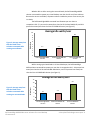
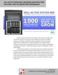
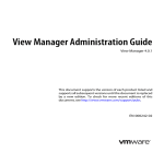
Whether idle or while running the test workloads, the Dell PowerEdge M620
solution consumed less power per virtual desktop user than the HP and Cisco solutions.
Because the servers are blades, all power numbers include the power of one server plus
its chassis.
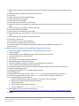
The Dell PowerEdge M620 consumed less idle watts per user than its
competitors did – 5.2 percent less watts/user than the HP ProLiant BL460c G8, and 63.1
percent less watts/user than the Cisco UCS B200 M3 server (see Figure 2).
Figure 2: Average watts/user
that the blade server
solutions consumed while
running no workloads.
Watts/user
Average idle watts/user
10
9
8
7
6
5
4
3
2
1
0
8.7
3.2
3.4
Dell PowerEdge M620
solution
HP ProLiant BL460c G8
solution
Cisco UCS B200 M3
solution
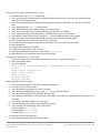
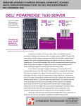
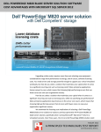
While running typical workloads in all virtual desktops, the Dell PowerEdge
M620 solution consumed less power per user than its competitors did – 4.4 percent less
watts/user than the HP ProLiant BL460c G8 solution, and 57.3 percent less watts/user
than the Cisco UCS B200 M3 solution (see Figure 3).
12
Average active watts/user
9.6
10
Watts/user
8
Figure 3: Average watt/user
that the blade server
solutions consumed while
running our test workloads.
6
4.1
4.3
Dell PowerEdge M620
solution
HP ProLiant BL460c G8
solution
4
2
0
Dell PowerEdge M620 blade server solutions for virtual desktop
infrastructures
Cisco UCS B200 M3
solution
A Principled Technologies test report 3
WHAT WE FOUND
For details on the results of our Login VSI tests, which show that each server
maxed out at 160 virtual desktops on each of the three server solutions, both in the 4second response time threshold and in CPU utilization, see Appendix D.
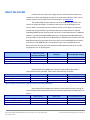
The standard Dell and HP enclosures can fit 16 blades each, while the Cisco
chassis can hold only 8 blades. To determine the cost per virtual desktop user the
servers deliver, we compare an even number of servers in full chassis, as a business
would have, using 16 blades. Figure 4 details the costs of these solutions. The Dell
PowerEdge M620 solution pricing includes 16 servers, 2 Dell PowerConnect™ M-8024-k
switches, and one PowerEdge M1000e enclosure; the HP ProLiant BL460c G8 solution
pricing includes 16 servers and one HP BladeSystem c7000 Enclosure; and the Cisco UCS
B200 M3 solution pricing includes 16 servers, two Cisco UCS 5108 Blade Server Chassis,
and two Cisco UCS 6248UP Fabric Interconnects. Lower costs and dollars/user are
better. All server prices are from the respective vendor Web sites and do not include
any discounts, tax, or shipping costs.
Total cost in USD
Cost/user
(16-server solutions)
Dell PowerEdge M620 solution
$249,107
$97.31
HP ProLiant BL460c G8 solution
$274,902
$107.38
Cisco UCS B200 M3 solution
$309,208
$120.78
Figure 4: Comparison of 16-server solution costs and cost/user for the solutions we tested.
Percentage Dell savings
9.4%
19.4%
Figure 5 details the wattage each solution consumed while idle and the
watts/user that each consumed. Lower watts and watts/user are better.
Watts (idle)
Watts/user
Dell PowerEdge M620 solution
511
3.2
HP ProLiant BL460c G8 solution
539
3.4
Cisco UCS B200 M3 solution
1,385
8.7
Figure 5: Watts and watts/user that the solutions consumed while idle.
Percentage Dell win
5.2%
63.1%
Figure 6 details the wattage each solution consumed while actively running our
test workloads and the watts/user that each consumed. Lower watts and watts/user are
better.
Watts (active)
Watts/user
Dell PowerEdge M620 solution
657
4.1
HP ProLiant BL460c G8 solution
687
4.3
Cisco UCS B200 M3 solution
1,539
9.6
Figure 6: Watts and watts/user that the solutions consumed while running workloads.
Dell PowerEdge M620 blade server solutions for virtual desktop
infrastructures
Percentage Dell win
4.4%
57.3%
A Principled Technologies test report 4
WHAT WE TESTED
About the Dell PowerEdge M620 blade server
The Dell PowerEdge M620 is a half-height two-socket blade server powered by
the Intel Xeon processor E5-2680 that can hold up to 768 GB of RAM in 24 DIMM slots.
The PowerEdge M620 comes standard with several management features, including
iDRAC7 Express with Lifecycle Controller for Blades, which allow administrators to
manage in physical or virtual environments locally or remotely. Along with other
members of the M-series PowerEdge server line, the PowerEdge M620 fits right in with
the power-efficient Dell PowerEdge M1000e Blade Enclosure.
For more information about the Dell PowerEdge M620, visit
http://www.dell.com/us/enterprise/p/poweredge-m620/pd.
About the Dell PowerEdge M1000e Blade Enclosure
The Dell PowerEdge M1000e blade chassis and its supported fabric
interconnects are designed for dense computing situations. Features of the PowerEdge
M1000e include:
Management. Reduces administrative demand by providing a secure centralized
management interface for the chassis and blades within, using proven Web
(SSL-encrypted) and CLI (SSH/Telnet) technologies.
Simplified configuration. The Chassis Management Controller allows
administrators to control up to nine enclosures and 144 server blades, including
BIOS/firmware change management and updates, thermal monitoring, and
power threshold configuration.
Flexible I/O. Six interconnect sockets with the capability to support three fullyredundant fabrics, a passive midplane with more than 8Tbps in I/O bandwidth
capacity, and FlexIO support provide a number of connectivity options for your
servers.
Reliability and efficiency. Six power supplies and nine fans, all hot- swappable,
allowing for no-downtime maintenance of key chassis components. All
components are tuned for maximum power efficiency to reduce data center
power consumption.
For more information about the Dell PowerEdge M1000e Blade Enclosure, visit
http://www.dell.com/us/enterprise/p/poweredge-m1000e/pd.
About Login VSI 3.6
Login Virtual Session Indexer (Login VSI) 3.6 is a tool that helps assess the virtual
desktop performance, capacity, and scalability of a server. After all desktops are idle,
Login VSI incrementally logs users into virtual desktop sessions and begins workloads on
each. Login VSI measures the total response times of seven typical office operations
Dell PowerEdge M620 blade server solutions for virtual desktop
infrastructures
A Principled Technologies test report 5
from each session and calculates the VSI Index Average by taking the average response
times and dropping the highest and lowest 2 percent.
As more sessions begin to consume system resources, response times degrade
and the VSI index increases until it is above the Dynamic VSImax. When this condition is
met, the benchmark records a Login VSImax, which is the maximum number of sessions
that the platform can support.
The newest version of Login VSI, Login VSI 3.6, includes client side performance
testing that test character response, large text response, mouse-click feedback, and
image quality and loading times on clients to ensure good end-user performance. In our
tests, we did not use the client-side testing portion of Login VSI, but instead used the
tool to determine how many virtual desktops the servers could support and to run the
Medium workload to tax the servers. For more information about Login VSI 3.6, see
http://www.loginvsi.com/product-overview.
IN CONCLUSION
Getting more value out of your blade solution is a smart way to reduce data
center and VDI costs. In our tests, the Dell PowerEdge M620 blade solution not only cost
up to 19.4 percent less per user than blade solutions from both HP and Cisco, it also
consumed as much as 63.1 percent less power per virtual desktop user. When
extrapolated over an entire chassis full of servers, and potentially data centers full of
these chassis, the potential savings both in hardware costs and power costs could be
dramatic.
Dell PowerEdge M620 blade server solutions for virtual desktop
infrastructures
A Principled Technologies test report 6
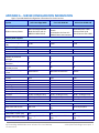
APPENDIX A – SERVER CONFIGURATION INFORMATION
Figure 7 provides detailed configuration information for the test servers.
System
Dell PowerEdge M620
Cisco UCS B200 M3
HP ProLiant BL460c G8
Enclosure/chassis
Blade enclosure/chassis
Chassis power supplies
Total number
Maximum wattage of each
(W)
Chassis cooling fans
Total number
Dimensions (h x w) of each
General
Number of processor
packages
Number of cores per
processor
Number of hardware
threads per core
System power management
power
CPU
Vendor
Name
Model number
Stepping
Socket type
Core frequency (GHz)
Bus frequency (GT/s)
L1 cache
L2 cache
L3 cache (MB)
Platform
Vendor and model number
BIOS name and version
Memory module(s)
Total RAM in system (GB)
Vendor and model number
Dell PowerEdge M1000e
Blade Enclosure with 2x
M8024-k 10GbE Switch
Cisco UCS 5108 Blade Server
Chassis
Connected to 2x Cisco UCS
6248UP Fabric Interconnects
HP BladeSystem c7000
Enclosure with 2x HP
Virtual Connect Flex-10Gb
6
4
6
2,700
2,500
2,450
9
3.1" x 3.5"
8
3-5/8" x 5-1/2"
10
4" x 4"
2
2
2
8
8
8
16
16
16
Performance
Maximum Performance
Default
Intel
Xeon
E5-2680
C2
LGA2011
2.7
8
32 KB + 32 KB (per core)
256 KB (per core)
20
Intel
Xeon
E5-2680
C2
LGA2011
2.7
8
32 KB + 32 KB (per core)
256 KB (per core)
20
Intel
Xeon
E5-2680
C2
LGA2011
2.7
8
32 KB + 32 KB (per core)
256 KB (per core)
20
Dell PowerEdge M620
Cisco UCS B200 M3
B200M3.2.0.3.0.0516201212
10
HP ProLiant BL460c G8
256
Samsung M393B2G70BH0YH9
256
Samsung M393B2G70BH0YH9
Dell 1.3.6
256
Samsung M393B2G70BH0YH9
Dell PowerEdge M620 blade server solutions for virtual desktop
infrastructures
HP I31 07/15/2012
A Principled Technologies test report 7
System
Type
Speed (MHz)
Speed running in the system
(MHz)
Size (GB)
Number of RAM module(s)
Chip organization
Rank
Operating system
Name
Build number
File system
Kernel
Language
RAID controller
Vendor and model number
Firmware version
Hard disk
Vendor and model number
Number of disks in system
Size (GB)
Buffer size (MB)
RPM
Type
Network adapter
Vendor and model number
USB ports
Number
Type
Dell PowerEdge M620
Cisco UCS B200 M3
HP ProLiant BL460c G8
PC3-10600
1,333
PC3-10600
1,333
PC3-10600
1,333
1,333
1,333
1,333
16
16
Double-sided
Dual
16
16
Double-sided
Dual
16
16
Double-sided
Dual
VMware ESXi 5.0.0
768111
VMFS
VMkernel 5.0.0
English
VMware ESXi 5.0.0
768111
VMFS
VMkernel 5.0.0
English
VMware ESXi 5.0.0
768111
VMFS
VMkernel 5.0.0
English
Dell PERC H310 Mini
20.10.1-0084
LSI™ MegaRaid™ SAS 2004
20.10.1-0061
HP Smart Array P220i
2.14
Fujitsu MBE2147RC
2
146
16
15,000
SAS
Toshiba MBF2300RC
2
300
16
10,000
SAS
HP EH0146FARWD
2
146
16
15,000
SAS
Intel 82599EB 10Gb Dual
Port
2x Cisco UCS-IOM-2208XP
2x HP Virtual Connect Flex10Gb
2
2.0
0
N/A
0
N/A
Figure 7: System configuration information for the test systems.
Dell PowerEdge M620 blade server solutions for virtual desktop
infrastructures
A Principled Technologies test report 8
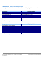
STORAGE INFORMATION
Figures 8 and 9 present detailed storage information for the two Dell EqualLogic PS6010 arrays we used in our
tests.
Storage array 1
Number of storage controllers per array
RAID level
Number of drives per array
Drive vendor and model number
Drive size (GB)
Drive buffer size (MB)
Drive RPM
Drive type
Dell EqualLogic PS6010
1
10
14 (12 active data drives, 2 spares)
Seagate ST3600002SS
600
16
10,000
SAS
Figure 8: Storage configuration information for the first Dell EqualLogic PS6010.
Storage array 2
Number of storage controllers per array
RAID level
Number of drives per array
Drive vendor and model number
Drive size (GB)
Drive buffer size (MB)
Drive RPM
Drive type
Dell EqualLogic PS6010
1
10
14 (12 active data drives, 2 spares)
Seagate ST3146855SS
146
16
15,000
SAS
Figure 9: Storage configuration information for the second Dell EqualLogic PS6010.
Dell PowerEdge M620 blade server solutions for virtual desktop
infrastructures
A Principled Technologies test report 9
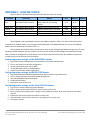
APPENDIX C - HOW WE TESTED
Figure 10 presents detailed information about the VMs we used in our testing.
VM name
Hosted OS
DC1
Win 2008 R2 x64 Enterprise
VMW-View
vCenter
Launcher
View-gold
Win 2008 R2 x64 Enterprise
Win 2008 R2 x64 Enterprise
Windows 7 x 86 Enterprise
Windows 7 x 86 Enterprise
Role (s)
AD Domain controller VSI Share,
DHCP, DNS, NTP, AD roaming
profiles
VMware View Connection server
VMware Virtual Center, Composer
Login VSI Master launcher
View master image
Host
Memory
# vCPUs
infra
4 GB
2
infra
infra
infra
vDT-host
4 GB
4 GB
4 GB
1 GB
4
4
2
1
Figure 10: Detailed VM configuration information.
We configured a Dell PowerEdge R710 server with VMware vSphere™ (ESXi) 5.0 to host all VDI infrastructure
components for VMware View 5.1 and configure a Dell M620 blade, a HP BL480c G8 blade and a Cisco UCS B200 M3
blade to host virtual desktops for VMware View 5.1.
We connected all the blades and the infrastructure server to two Dell EqualLogic PS6010 storage arrays. The Dell
EqualLogic PS6010 storage arrays have 14 disks each for a total of 4.55TB of usable storage. We created two Storage
Pools on a RAID 10 configuration and four volumes to host View Composer linked clones. One additional volume was
created to host the infrastructure virtual machines.
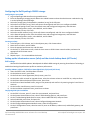
Configuring power settings on the Dell M1000e chassis
1.
2.
3.
4.
5.
Log into Dell Chassis Management Controller Web interface using a web browser.
Click on the Power tab and select configuration.
Set the System Input Power Cap to 100%.
Set the Redundancy Policy to AC Redundancy.
Enable Dynamic Power Supply Engagement.
Configuring power settings on the HP c7000 chassis
1.
2.
3.
4.
5.
Log into HP BladeSystem Onboard Administration Web interface using a web browser.
Click on Power and Thermal and select Power Management.
Select AC Redundant under Power Mode.
Enable Dynamic Power.
Select None under Power Limit.
Configuring power settings on the Cisco UCS 5108 chassis
1. Log into Cisco Unified Computing System Manager.
2. Click on Service Profiles and click New to create a new Service Profile.
3. Enter a profile name and description, configure vNICs, vHBA connections, boot order and server association.
Click Ok.
4. Double Click the Service Profile and select the Policies Tab.
5. Select the Power Control Policy and create a new policy with no power cap.
6. Click Apply, Click OK.
Dell PowerEdge M620 blade server solutions for virtual desktop
infrastructures
A Principled Technologies test report 10
Configuring the Dell EqualLogic PS6010 storage
Configuring the array RAID
1. Log into EqualLogic Web interface using a web browser.
2. Enter the EqualLogic storage group IP address into a Web browser and use the administrator credentials to log
in to the EqualLogic Group Manager.
3. Select the storage group, and expand the members (arrays) in the left pane.
4. Select the first member (array), which will show as unconfigured, and click Yes to configure the RAID.
5. At the General Settings screen, leave the default name and storage pool assignment, and click Next.
6. At the RAID configuration screen, select RAID 10, and click Next.
7. At the Summary screen, click Finish.
8. Select the second member (array), which will show as unconfigured, and click Yes to configure the RAID.
9. At the General Settings screen, leave the default name and storage pool assignment, and click Next.
10. At the RAID configuration screen, select RAID 10, and click Next.
11. At the Summary screen, click Finish.
Creating a volume
1. In the left pane, click Volumes, and, in the adjacent pane, click Create volume.
2. Name the first volume, and click Next.
3. Enter the appropriate volume size, and click Next.
4. On the Step 3 – iSCSI Access screen, check the Limit access to iSCSI initiator name checkbox, and enter the
appropriate iSCSI initiator names.
5. Click Finish.
6. Repeat steps 1 – 5 to create additional volumes.
Setting up the infrastructure server (infra) and the virtual desktop hosts (vDT-hosts)
BIOS settings
We used the latest BIOS updates. We adjusted the default BIOS settings by ensuring Virtualization Technology is
enabled and setting the performance profile to maximum performance.
Installing VMware vSphere 5.0 (ESXi) on PowerEdge R710s (infra) and (vDT-Hosts)
1. Insert the ESXi 5.0 disk, and select Boot from disk.
2. On the Welcome screen, press Enter.
3. On the End User License Agreement (EULA) screen, press F11.
4. On the Select a Disk to install or Upgrade Screen, select the relevant volume to install ESXi on, and press Enter.
5. On the Please Select a Keyboard Layout screen, press Enter.
6. On the Enter a Root Password Screen, assign a root password, and confirm it by entering it again. Press Enter to
continue.
7. On the Confirm Install Screen, press F11 to install.
8. On the Installation complete screen, press Enter to reboot.
Configuring ESXi after installation
1. On the ESXi 5.0 screen, press F2, enter the root password, and press Enter.
2. On the System Customization screen, select Troubleshooting Options, and press Enter.
3. On the Troubleshooting Mode Options screen, select enable ESXi Shell, and press Enter.
4. Select Enable SSH, press Enter, and press Esc.
5. On the System Customization screen, select Configure Management Network.
6. On the Configure Management Network screen, select IP Configuration.
7. On the IP Configuration screen, select Set static IP; enter an IP address, subnet mask, and default gateway; and
press Enter.
Dell PowerEdge M620 blade server solutions for virtual desktop
infrastructures
A Principled Technologies test report 11
8. On the Configure Management Network screen, press Esc. When asked if you want to apply the changes, press
Y.
9. Log into infra as root with the vSphere client.
10. Select the Configuration tab, and click Networking.
11. Click Add Networking…
12. Create a virtual machine network called PRIV-NET and select the appropriate adapters.
13. Click OK.
14. Select the Configuration tab, and click Time configuration.
15. Select Properties, and click Options.
16. In the General settings, select Start automatically if any ports are open, and Stop when all ports are closed.
17. In the NTP settings, add a reliable NTP server, or use DC1.VDI.com.
18. Close NTP settings.
19. Select the Configuration tab, and click DNS and routing.
20. Type infra for name, and VDI.com for domain.
21. Enter 172.0.0.10 for preferred DNS.
22. Close DNS.
Creating the ESXi datastores
1.
2.
3.
4.
5.
6.
7.
8.
9.
10.
11.
12.
Log into infra as root with the vSphere client.
Click Configuration tabStorage AdaptersAdd…
Select Add Software iSCSI Adapter, and click OK.
Select the iSCSI adapter and click on Properties…
Select the Dynamic Discovery tab and click on Add…
Enter the iSCSI Server IP and click OK.
Select Rescan All…
Selected the newly discovered volume.
For Datastore name, type LUN1 and click Next.
For Capacity, select Maximum Available Space, and click Next.
Click Finish to create the datastore.
Repeat steps 8 through 11 to create additional datastores.
Setting up a VM to host Microsoft Windows Active Directory® server (DC1) on (infra) server
1.
2.
3.
4.
5.
6.
7.
8.
9.
10.
11.
12.
13.
14.
15.
16.
Connect to the infra server via the VMware vSphere client.
Log in as root to the infra server.
In the vSphere client, connect to the vCenter™ Server, and browse to the ESXi host.
Click the Virtual Machines tab.
Right-click, and choose New Virtual Machine.
Choose Custom, and click Next.
Assign the name DC1 to the virtual machine, and click Next.
Select infra for the host, and click Next.
Select infraLUN for the storage, and click Next.
Choose Virtual Machine Version 8, and click Next.
Choose Windows, choose Microsoft Windows Server® 2008 R2 (64-bit), and click Next.
For CPUs, select one virtual processor socket, and 2 cores per virtual socket, and click Next.
Choose 4 GB RAM, and click Next.
Click 1 for the number of NICs, select VMXNET3, connect to the PRIV-NET network, and click Next.
Leave the default virtual storage controller, and click Next.
Choose to create a new virtual disk, and click Next.
Dell PowerEdge M620 blade server solutions for virtual desktop
infrastructures
A Principled Technologies test report 12
17. Make the OS virtual disk size 40 GB, choose thick-provisioned lazy zeroed, specify external storage, and click
Next.
18. Keep the default virtual device node (0:0), and click Next.
19. Click Finish.
20. Right-click the VM, and choose Edit Settings.
21. On the Hardware tab, click Add…
22. Click Hard Disk, and click Next.
23. Click Create a new virtual disk, and click Next.
24. Specify 15 GB for the virtual disk size, choose thick-provisioned lazy zeroed, specify external storage, and click
Next.
25. Choose SCSI (0:1) for the device node, and click Next.
26. On the Hardware tab, click Add…
27. Click Create a new virtual disk, and click Next.
28. Specify 50 GB for the virtual disk size, choose thick-provisioned lazy zeroed, specify external storage, and click
Next.
29. Choose SCSI (0:2) for the device node, and click Next.
30. Click Finish, and click OK.
31. Click the Resources tab, and click Memory.
32. Select Reserve all guest memory, and click OK.
33. Connect the VM virtual CD-ROM to the Microsoft Windows Server 2008 R2 installation disk.
34. Start the VM.
Installing the Microsoft Windows Server 2008 R2 operating system on the VM
1. Choose the language, time and currency, and keyboard input. Click Next.
2. Click Install Now.
3. Choose Windows Server 2008 R2 Enterprise (Full Installation), and click Next.
4. Accept the license terms, and click Next.
5. Click Custom.
6. Click the Disk, and click Drive options (advanced).
7. Click NewApplyFormat, and click Next.
8. After the installation completes, click OK to set the Administrator password.
9. Enter the administrator password twice, and click OK.
10. Connect the machine to the Internet, and install all available Windows updates. Restart as necessary.
11. Enable remote desktop access.
12. Change the hostname to DC1 and reboot when prompted.
13. Run diskmgmt.msc.
14. Select the 15 GB secondary volume, name it profiles format it NTFS, and assign it drive letter E
15. Select the 50 GB secondary volume, name it share format it NTFS, and assign it drive letter F
16. Set up networking for the data network:
a. Click StartControl Panel, right-click Network Connections, and choose Open.
b. Right-click the VM traffic NIC, and choose Properties.
c. Uncheck TCP/IP (v6).
d. Select TCP/IP (v4), and choose Properties.
e. Set the IP address as 172.0.1.10/255.255.252.0
17. Install VMware Tools. For more information, see
http://kb.vmware.com/selfservice/microsites/search.do?language=en_US&cmd=displayKC&externalId=340
18. Reboot.
Dell PowerEdge M620 blade server solutions for virtual desktop
infrastructures
A Principled Technologies test report 13
Installing Active Directory and DNS services on DC1
1. Click StartRun, type dcpromo and click OK.
2. At the Active Directory Domain Services Installation Wizard welcome screen, check the Use advanced mode
installation option, and click Next.
3. In the Choose a Deployment Configuration dialog box, select Create a new domain in a new forest, and click
Next.
4. At the FQDN page, type VDI.com and click Next.
5. At the NetBIOS name prompt, leave the name VDI, and click Next.
6. At the Forest Functionality level, select Windows Server 2008 R2, and click Next.
7. At the additional Domain Controller Options, leave DNS server selected, and click Next.
8. At the System Folder Location screen, change to E:\ leave the default options, and click Next.
9. Assign a Directory Services Restore Mode Administrator account password, and click Next.
10. At the Summary screen, review your selections, and click Next.
11. Once Active Directory Domain Services finishes installing, click Finish, and restart the system.
12. Run dnsmgmt.msc.
13. Create a reverse lookup zone for DC1.
14. Create static entries for infra and vDT-host.
15. Open Windows Explorer, and create a folder called e:\profiles
16. Assign permissions of read/write to the VDI\everyone group.
Configuring the Windows time service on DC1
To ensure reliable time, we pointed our Active Directory server to a physical NTP server.
1. Open a command prompt.
2. Type the following:
W32tm /config /syncfromflags:manual /manualpeerlist:"<ip address of a NTP
server>"
W32tm /config /reliable:yes
W32tm /config /update
W32tm /resync
Net stop w32time
Net start w32time
Setting up DHCP services on DC1
1.
2.
3.
4.
5.
6.
7.
8.
9.
10.
11.
Click StartAdministrative ToolsServer ManagerAdd Roles.
Select DHCP Server, and click Next.
At the Introduction to DHCP Server screen, click Next.
At the Specify IPv4 DNS Settings screen, type vdi.com for the parent domain.
Type the preferred DNS server IPv4 address, and click Next.
At the Specify IPv4 WINS Server Settings screen, select WINS is not required for applications on the network, and
click Next.
At the Add or Edit DHCP Scopes screen, click Add.
At the Add Scope screen, enter the Name DHCP Scope name.
In the next box, set the following values, and click OK.
Start IP address=172.0.0.101
End IP address=172.0.3.200
Subnet mask=255.255.252.0
Check the Activate This Scope box.
At the Add or Edit DHCP Scopes screen, click Next.
Dell PowerEdge M620 blade server solutions for virtual desktop
infrastructures
A Principled Technologies test report 14
12.
13.
14.
15.
Click the Enable DHCP v6 Stateless Mode radio button, and click Next.
Leave the default IPv6 DNS Settings, and click Next.
At the Authorize DHCP server dialog box, select Use current credentials.
At the Confirm Installation Selections screen, click Next. If the installation is set up correctly, a screen displays
saying that DHCP server install succeeded.
16. Click Close.
Setting up the Login VSI share and Active Directory users
For Login VSI to work correctly, you must create a CIFS share, Active Directory OU, and Active directory. For
more information on Login VSI, see http://www.loginvsi.com/en/admin-guide/installation.html. Open Windows
Explorer, and create a file called f:\share and e:\profiles
1.
2.
3.
4.
5.
6.
Assign permissions of read/write to the VDI/everyone group.
Right-click the f:\share and e:\profiles folders, and select Properties.
Click the Sharing tab, and click Share…
Add everyone to the Read/Write group, and click Share.
From the Login VSI 3.6 media, run the Login VSI AD Setup.
Keep the defaults, and click Start.
Creating roaming profiles for users
1.
2.
3.
4.
5.
6.
Open Active Directory Users and Computers.
Browse to VDI.comLogin_VSIUsersTarget.
Select all Login VSI users, and right-click Properties.
Click the Profiles tab.
Check box Profile path, and type e:\profiles\%username%
Click OK.
Setting up a VM to host the vCenter server (vCenter)
1.
2.
3.
4.
5.
6.
7.
8.
9.
10.
11.
12.
13.
14.
15.
16.
17.
Connect to the infra server via the vSphere client.
Log into infra with the VMware vSphere client.
In the vSphere client, connect to the vCenter Server, and browse to the ESXi host.
Click the Virtual Machines tab.
Right-click, and choose New Virtual Machine.
Choose Custom, and click Next.
Assign the name vCenter to the virtual machine, and click Next.
Select infra for the host, and click Next.
Select infraLUN for the storage, and click Next.
Choose Virtual Machine Version 8, and click Next.
Choose Windows, choose Microsoft Windows Server 2008 R2 (64-bit), and click Next.
For CPUs, select one virtual processor socket, and 2 cores per virtual socket, and click Next.
Choose 4GB RAM, and click Next.
Click 1 for the number of NICs, select VMXNET3, connect to the PRIV-NET portgoup, and click Next.
Leave the default virtual storage controller, and click Next.
Choose to create a new virtual disk, and click Next.
Make the OS virtual disk size 40 GB, choose thick-provisioned lazy zeroed, specify the OS datastore on the
external storage, and click Next.
18. Keep the default virtual device node (0:0), and click Next.
19. Connect the VM virtual CD-ROM to the Microsoft Windows 2008 R2 installation disk.
20. Click Finish.
Dell PowerEdge M620 blade server solutions for virtual desktop
infrastructures
A Principled Technologies test report 15
21. Right-click the vCenter VM, and click Edit settings.
22. Click the Resources tab, click Memory, check the Reserve all guest memory checkbox, and click OK.
23. Start the VM.
Installing the Microsoft Windows Server 2008 R2 operating system on the VM
1.
2.
3.
4.
5.
6.
7.
8.
9.
10.
11.
12.
13.
14.
15.
16.
17.
Choose the language, time and currency, and keyboard input. Click Next.
Click Install Now.
Choose Windows Server 2008 R2 Enterprise (Full Installation), and click Next.
Accept the license terms, and click Next.
Click Custom.
Click the Disk, and click Drive options (advanced).
Click NewApplyFormat, and click Next.
After the installation completes, click OK to set the Administrator password.
Enter the administrator password twice, and click OK.
Connect the machine to the Internet, and install all available Windows updates. Restart as necessary.
Enable remote desktop access.
Change the hostname to vCenter and reboot when prompted.
Set up networking for the data network:
a. Click Start, Control Panel, right-click Network Connections, and choose Open.
b. Right-click the VM traffic NIC, and choose Properties.
c. Uncheck TCP/IP (v6).
d. Select TCP/IP (v4), and choose Properties.
e. Set the IP address, subnet, gateway, and DNS server.
Join the VDI domain.
Reboot the system.
Install VMware Tools. For more information, see
http://kb.vmware.com/selfservice/microsites/search.do?language=en_US&cmd=displayKC&externalId=340.
Reboot.
Installing VMware vCenter 5
1.
2.
3.
4.
5.
6.
7.
8.
9.
10.
11.
12.
13.
14.
15.
16.
17.
18.
19.
Log onto the vCenter as VDI\administrator
From the VMware vCenter5 install media, click Autorun.
Click Run to start the install wizard.
Click the Install button on the VMware vSphere 5.0 wizard.
Select the Install wizard language as English, and click OK.
At the Install wizard welcome screen, click Next.
Agree to the license agreement, and click Next.
Enter user information and a license key, and click Next.
Select Install the SQL express instance, and click Next.
Select the system account for the vCenter Server service account, and click Next.
Keep the installation directory as C:\Program Files\VMware\Infrastructure\, and click Next.
Select Create a standalone VMware vCenter Server instance, and click Next.
Keep the vCenter default ports, and click Next.
Select 1024 MB for the JVM memory, and click Next.
Click Install to finish the vCenter server installation.
Restart the server when complete.
Using the vSphere client, log into vCenter5 as VDI\administrator
Right-click the root of vCenter, and click New Data center.
Name the New datacenter VDI
Dell PowerEdge M620 blade server solutions for virtual desktop
infrastructures
A Principled Technologies test report 16
20. Add the ESX server named vDT-Host to the datacenter.
21. Add the ESX server named infra to the datacenter.
Setting up ODBC DSN for composer
1. From the vCenter desktop, open StartAll ProgramsMicrosoft SQL Server 2008 R2Configuration
ToolsSQL Server Configuration Manager.
2. Click SQL Server Network ConfigurationProtocols for VIM_SQLEXP.
3. Right-click TCP/IP, and select Enabled.
4. Click SQL Servicesright-click SQL Server Browser, and select Properties.
5. IN the SQL Server Browser properties, select the Services tab, change the Start mode to Automatic, and click OK.
6. Start the SQL Server browser service.
7. Select StartRunodbcad32.exe.
8. Click the system DSN tab.
9. Click Add.
10. Click SQL Server, and click Finish.
11. In the Create a New Data Source to SQL Server text box, enter the connection name type: composer
12. For Server, select vCenter\VIM_SQLEXP, and click Next.
13. Leave authentication as default, click Next twice, and click Finish.
14. Click OK to create the composer ODBC connection.
Setting up VMware View Composer
1. Open the View5 media folder, and run the file names VMware-viewcomposer-.3.0.0-691993.exe.
2. At the Welcome screen and the Patents screen, click Next.
3. Accept the VMware end user license agreement, and click Next.
4. Leave the Destination folder as default, and click Next.
5. In the Database information box, for source name type composer for user name type VDI\Administrator
type the password, and click Next.
6. Leave the default SOAP port, and click Next.
7. Click Install, and click finish.
Setting up a VM to host the VMware View connection server
1.
2.
3.
4.
5.
6.
7.
8.
9.
10.
11.
12.
13.
13.
14.
15.
Log into vCenter with the VMware vSphere client.
In the vSphere client, browse to the ESXi host named infra.
Click the Virtual Machines tab.
Right-click, and choose New Virtual Machine.
Choose Custom, and click Next.
Assign the name View5 to the virtual machine, and click Next.
Select infra for the host, and click Next.
Select infraLUN for the storage, and click Next.
Choose Virtual Machine Version 8, and click Next.
Choose Windows, choose Microsoft Windows Server 2008 R2 (64-bit), and click Next.
For CPUs, select one virtual processor socket, and 2 cores per virtual socket, and click Next.
Choose 4GB RAM, and click Next.
Click 1 for the number of NICs, select VMXNET 3, connect to the PRIV-NET portgroup, and click Next.
Leave the default virtual storage controller, and click Next.
Choose to create a new virtual disk, and click Next.
Make the OS virtual disk size 40 GB, choose thick-provisioned lazy zeroed, specify the OS datastore on the
external storage, and click Next.
16. Keep the default virtual device node (0:0), and click Next.
Dell PowerEdge M620 blade server solutions for virtual desktop
infrastructures
A Principled Technologies test report 17
17. Connect the VM virtual CD-ROM to the Microsoft Windows Server 2008 R2 installation disk.
18. Right-click the View5 VM, and click Edit settings.
19. Click the Resources tab, click Memory, check the Reserve all guest memory checkbox, and click OK.
20. Click Finish.
21. Start the VM.
Installing the Microsoft Windows Server 2008 R2 operating system on the VM
1. Choose the language, time and currency, and keyboard input. Click Next.
2. Click Install Now.
3. Choose Windows Server 2008 R2 Enterprise (Full Installation), and click Next.
4. Accept the license terms, and click Next.
5. Click Custom.
6. Click the Disk, and click Drive options (advanced).
7. Click NewApplyFormat, and click Next.
8. After the installation completes, click OK to set the Administrator password.
9. Enter the administrator password twice, and click OK.
10. Connect the machine to the Internet, and install all available Windows updates. Restart as necessary.
11. Enable remote desktop access.
12. Change the hostname to VMW-View and reboot when prompted.
13. Set up networking for the data network:
a. Click StartControl Panel, right-click Network Connections, and choose Open.
b. Right-click the VM traffic NIC, and choose Properties.
c. Uncheck TCP/IP (v6).
d. Select TCP/IP (v4), and choose Properties.
e. Set the IP address, subnet, gateway, and DNS server.
14. Join the VDI domain.
15. Install VMware Tools. For more information, see
http://kb.vmware.com/selfservice/microsites/search.do?language=en_US&cmd=displayKC&externalId=340.
16. Reboot.
Installing the VMware View Connection Server
1. Log into the server named VMW-View.
2. Click Install Media for View Connection Server x86_64-5.1.0-704644.exe
3. To begin the install wizard, click Next.
4. Agree to the license agreement, and click Next.
5. Keep the destination directory as C:\Program Files\VMware View\Server\, and click Next.
6. Select View Standard Server, and click Next.
7. Allow View Server to configure the firewall, and click Next.
8. Authorize the local administrator to administer View and click Next.
9. Choose whether to participate in the customer experience improvement program.
10. Complete the installation wizard to finish installing View Connection Server
11. Click Finish.
12. Reboot server.
Configuring the VMware View Connection Server
1. Open a Web browser to <the view server ipaddress>/admin.
2. Log in as administrator
3. Open View ConfigurationServers.
4. In the vCenter Servers tab, click Add…
Dell PowerEdge M620 blade server solutions for virtual desktop
infrastructures
A Principled Technologies test report 18
5.
6.
7.
8.
9.
10.
In the Add vCenter Server settings, add the vCenter, and enable View Composer. Click OK.
Set the Host Cache setting to 2048MB.
Open View ConfigurationProduct Licensing and Usage.
Click Edit license…
Enter a valid license serial number, and click OK.
Close the View Administrator.
Setting up a Windows 7 Enterprise x86 image template
Using the vSphere client, we created a Windows Enterprise X86 VMs base image and converted it into a
template. Using our template, we deployed a View gold image and a Login VSI launcher.
On the gold image, we installed Microsoft Office 2010, installed the Login VSI target software, added them to
the VDI domain, added them to the Login VSI OU, and installed the respective VMware View 5.1 agents.
For the Login VSI launcher VM, we installed the VMware View 5.1 client, added it to the VDI domain and Login
VSI OU in Active Directory, and installed the Login VSI Launcher software.
Installing the Windows 7 Enterprise (x86) base image VM
1.
2.
3.
4.
5.
6.
7.
8.
9.
10.
11.
12.
13.
14.
15.
16.
17.
18.
19.
20.
21.
22.
23.
Log into the vCenter.
In the vSphere client, connect to the vCenter Server, and browse to the infra host.
Click the Virtual Machines tab.
Right-click, and choose New Virtual Machine.
Choose Custom, and click Next.
Assign the name as win7-temp and click Next.
Select infra for the host, and click Next.
Select infraLUN.
Choose Virtual Machine Version 8, and click Next.
Choose Windows, choose Microsoft Windows 7 (32-bit), and click Next.
For CPUs, select one virtual processor socket and one core per virtual socket, and click Next.
Choose 1GB RAM, and click Next.
Click 1 for the number of NICs, select VMX, and click Next.
Leave the default virtual storage controller, and click Next.
Choose to create a new virtual disk, and click Next.
Make the OS virtual disk size 20 GB, choose thick-provisioned lazy zeroed, specify the OS datastore on the
external storage, and click Next.
Keep the default virtual device node (0:0), and click Next.
Click Finish.
Click Finish, and click OK.
Right-click the win7-temp VM, and click Edit settings.
Click the Resources tab, click Memory, and check the Reserve all guest memory checkbox.
Click the Hardware tab, CD/DVD Drive, and Connect the VM virtual CD-ROM to the Microsoft Windows 7 x86
installation disk.
Click OK.
Installing the Windows 7 Enterprise (X86) on the base image VM
1.
2.
3.
4.
5.
When the installation prompts you, press any key to begin setup.
Enter your language preferences, and click Next.
Click Install.
Accept the license terms, and click Next.
Select Custom, and select the drive that will contain the OS.
Dell PowerEdge M620 blade server solutions for virtual desktop
infrastructures
A Principled Technologies test report 19
6.
7.
8.
9.
10.
11.
12.
13.
Click Install, and the setup begins.
Type user for the username and change the computer name, and click Next.
Enter no password, and click Next.
For system protection, select Use recommended settings, and click Next.
Enter your time zone, and click Next.
Select the Work Network setting, and click Next.
Use Windows Update to patch the Windows 7 installation.
Install VMware Tools from
http://kb.vmware.com/selfservice/microsites/search.do?language=en_US&cmd=displayKC&externalId=340.
14. Reboot.
Installing Windows 7 Enterprise (X86), optimizing Windows 7
Adjusting page file
1. Log in as administrator
2. Right-click ComputerPropertiesChange settingsAdvancedPerformanceSettings.
3. In Performance settings, select the Advanced tab, and select Change for Virtual Memory.
4. Deselect automatically manage page file.
5. Select Custom size, type 2048 for both values, and select Set.
Enabling ClearType fonts
1. Click StartRun, and type cttune.exe
2. Check the Turn on ClearType checkbox, and click Next.
3. Follow the wizard to enable ClearType fonts.
Disabling Windows Firewall
The domain GPO automatically disables the Windows Firewall.
Installing Office 2010 Professional and converting to template
1. From the Office 2010 media, run Setup.
2. Enter the product key for Office 2010, and click Continue.
3. Accept the licensing agreement.
4. Select Install Now.
5. Reboot the system.
6. Shut down the VM.
7. Right-click, and select TemplateConvert to Template.
Deploying the view_gold image from template
1. In vSphere Client, browse to HomeVMs and Templates.
2. Right-click win7-temp to deploy a virtual machine from template.
3. For Name, type view_gold and click Next.
4. Click Datacenter, and click Next.
5. Click the vDT-host server, and click Next.
6. Select infraLUN, and click Next.
7. Select customization using existing customization specifications, select the appropriate file, and click Next.
8. Click Finish to deploy the view_gold VM.
9. Repeat steps 1 through 8 to deploy a Launcher_1 VM to host infra.
Preparing view_gold for deployment
Installing Login VSI target software on view_gold
1. Log into the view_gold VM as VDI\administrator
Dell PowerEdge M620 blade server solutions for virtual desktop
infrastructures
A Principled Technologies test report 20
2. Browse to \vsi-install\Target setup.
3. Run the setup.exe.
4. In the Target Setup wizard, specify the VSI share \\dc1\share
5. Click Start.
6. At the security warnings, click OK.
7. Reboot the system.
Installing the View 5 agent on view_gold
1. Browse to the VMware View 5 media, and run the VMware-viewagent-x86_64-5.1.0-704644.exe file.
2. Click Run.
3. At the Welcome screen, click Next.
4. Accept the VMware end user license agreement, and click Next.
5. Select defaults, and click Next.
6. Enter the server name of the View Connection Server, and click Next.
7. Click Install.
Configuring Regedit for Quick prep (kb.vmware.com/kb/1026556)
1.
2.
3.
4.
Click StartRun, and type regedit
Browse to HKEY_LOCAL_MACHINE\SYSTEM\CurrentControlSet\Services\vmware-viewcomposer-ga.
Right-click SkipLicenseActivation, and click Modify…
Change the value from 0 to 1.
Preparing Launcher_1 for testing
We installed our launcher with the Login VSI target software and View 5.1 client.
Installing Virtual Audio Cables
By default, the virtual launchers cannot render audio so we installed Virtual Audio Cables version 4.10. The
software can be downloaded from http://software.muzychenko.net/eng/vac.htm
1. Download and extract the media.
2. Click Setup.
3. Click Yes to begin the install.
4. Click I accept to accept the software license agreement.
5. Click Install.
Installing the Login VSI launcher
1. Log into the XD_gold VM as VDI\administrator
2. Browse to \vsi-install\Launcher setup.
3. Run the setup.exe.
4. In the Target Setup wizard, specify the VSI share \\dc1\share
Patching the Login VSI launcher and updating the version of Adobe Flash
By default, Login VSI installs an older version of Flash. To ensure Flash Media Redirection works, ensure that the
launcher version is 3.4.1 or greater and that adobe Flash player 11 plugin has been updated. It can be found here:
http://www.adobe.com/support/flashplayer/downloads.html.
Installing the VMware View client
1. Browse to the VMware View 5.1 media, and run the VMware-viewclient-x86_64-5.1.0-704644.exe file.
2. Click Run.
3. At the welcome screen, click Next.
4. At the Patents screen, click Next.
Dell PowerEdge M620 blade server solutions for virtual desktop
infrastructures
A Principled Technologies test report 21
5. Accept the VMware end user license agreement, and click Next.
6. Select defaults, and click Next.
7. Click Install.
Configuring View 5 - creating a pool and adding entitlements for Login VSI users
1.
2.
3.
4.
5.
6.
7.
8.
9.
10.
11.
12.
13.
14.
15.
16.
17.
18.
19.
20.
21.
22.
Open vCenterDatacenterInfra, and right-click the view_gold VM, select SnapshotTake Snapshot.
Name the snapshot view_gold
Open the View Administrator.
Log in as administrator
Click Pools, and in the right window, click Add…
Select Automatic Pool, and click Next.
Select Floating, and click Next.
Select View Composer linked clones, and click Next.
Type pool for the pool ID and display name, and click Next.
Leave the pool settings as defaults, and click Next.
For the naming pattern, type View-{n:fixed=003}
Under Pool Sizing enter 160 for Max number of desktops and Number of spare (power on) desktops.
Select provision all desktops up-front, and click Next.
Select Redirect disposable files to a non-persistent disk, type 4096 MB for Disk Size, and click Next.
Under Storage Optimization, click Next.
For the pool settings, use the following:
Default image: view_gold – view_gold
VM folder: /Datacenter/vm/Pool
Host or cluster: DataCenter/host/vd-host.vdi.com
Resource pool: /Datacenter/host/vd-host.vdi.com/Resources
Datastore= LUN1,LUN2,LUN3,LUN4 Storage Overcommit: Conservative
Under Advanced Storage Options select Use host caching, OS disk, 7 days, and click Next.
For Guest customization, select the following:
Domain: VDI.com
AD container: OU=Users,OU=Login_VSI
Select Use Quick Prep, and click Next.
Click Finish.
Click Pool, and click Entitlements…
Click Add, type Login_VSI_TS and click OK.
Click Desktops, and wait for the virtual desktops to report as ready.
Dell PowerEdge M620 blade server solutions for virtual desktop
infrastructures
A Principled Technologies test report 22
APPENDIX D – DETAILED TEST RESULTS
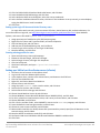
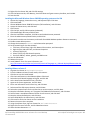
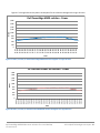
Figures 11 through 13 show the Login VSI response times throughout our tests at varying user counts. From
these results, we determined that each server solution could comfortably support 160 virtual desktops while
maintaining acceptable response times.
Dell PowerEdge M620 - Login VSI response times
4,000
3,500
Response time (ms)
3,000
2,500
2,000
1,500
1,000
500
0
10
22
30
40
48
55
63
71
79
88
97
106 114 123 132 140 149 160
Users
Figure 11: Login VSI response times for the Dell PowerEdge M620 server throughout our Login VSI tests.
HP ProLiant BL460c G8 - Login VSI response times
4,500
4,000
Response time (ms)
3,500
3,000
2,500
2,000
1,500
1,000
500
0
10
22
30
40
48
55
63
71
79
88
97
106 114 123 132 140 149 160
Users
Figure 12: Login VSI response times for the HP ProLiant BL460c G8 server throughout our Login VSI tests.
Dell PowerEdge M620 blade server solutions for virtual desktop
infrastructures
A Principled Technologies test report 23
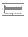
Cisco UCS B200 M3 - Login VSI response times
4,500
4,000
3,500
Response time (ms)
3,000
2,500
2,000
1,500
1,000
500
0
10
22
30
40
48
55
63
71
79 88
Users
97
106 114 123 132 140 149 160
Figure 13: Login VSI response times for the Cisco UCS B200 M3 server throughout our Login VSI tests.
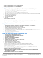
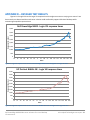
Figures 14 through 16 show the processor utilization percentage for the servers throughout the Login VSI tests.
Dell PowerEdge M620 - CPU %
100
CPU utilization percentage
90
80
70
60
50
40
30
20
10
06:46.0
08:23.0
10:03.0
11:46.0
13:30.0
15:13.0
17:00.0
18:47.0
20:36.0
22:23.0
24:12.0
26:05.0
28:01.0
29:58.0
31:58.0
34:01.0
36:06.0
38:09.0
40:12.0
42:13.0
44:14.0
46:16.0
48:17.0
50:18.0
52:19.0
54:08.0
55:55.0
57:38.0
59:22.0
01:00.0
02:40.0
04:16.0
05:53.0
0
Time
Figure 14: CPU utilization for the Dell PowerEdge M620 server throughout our Login VSI tests.
Dell PowerEdge M620 blade server solutions for virtual desktop
infrastructures
A Principled Technologies test report 24
27:25.0
29:16.0
31:18.0
33:07.0
34:57.0
36:53.0
38:49.0
40:44.0
42:35.0
44:27.0
46:24.0
48:21.0
50:23.0
52:35.0
54:44.0
56:52.0
59:15.0
01:35.0
03:47.0
05:53.0
07:31.0
09:09.0
10:42.0
12:32.0
14:25.0
15:57.0
17:22.0
18:43.0
20:10.0
21:31.0
22:52.0
23:44.0
24:34.0
25:23.0
CPU utilization percentage
0:00:06
0:01:54
0:03:42
0:05:30
0:07:18
0:09:06
0:10:54
0:12:42
0:14:30
0:16:18
0:18:06
0:19:54
0:21:42
0:23:30
0:25:18
0:27:06
0:28:54
0:30:42
0:32:30
0:34:18
0:36:06
0:37:54
0:39:42
0:41:30
0:43:18
0:45:06
0:46:54
0:48:42
0:50:30
0:52:18
0:54:06
0:55:54
0:57:42
0:59:30
CPU utilization percentage
HP ProLiant BL460c G8 - CPU %
100
90
80
70
60
50
40
30
20
10
0
Time
Figure 15: CPU utilization for the HP ProLiant BL460c G8 server throughout our Login VSI tests.
Cisco UCS B200 M3 - CPU%
100
90
80
70
60
50
40
30
20
10
0
Time
Figure 16: CPU utilization for the Cisco UCS B200 M3 server throughout our Login VSI tests.
Dell PowerEdge M620 blade server solutions for virtual desktop
infrastructures
A Principled Technologies test report 25
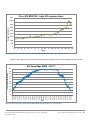
Figures 17 through 19 show the power consumption for the solutions throughout the Login VSI tests.
Dell PowerEdge M620 solution - Power
1,800
1,600
1,400
Watts
1,200
1,000
800
600
400
200
00:01.0
01:57.0
01:53.0
03:49.0
05:45.0
07:41.0
09:37.0
11:33.0
13:29.0
15:25.0
17:21.0
19:17.0
21:13.0
23:09.0
25:05.0
27:01.0
28:57.0
30:53.0
32:49.0
34:45.0
36:41.0
38:37.0
40:33.0
42:29.0
44:25.0
46:21.0
48:17.0
50:13.0
52:09.0
54:05.0
56:01.0
57:57.0
0
Time
Figure 17: Power, in watts, for the Dell PowerEdge M620 solution throughout our Login VSI tests.
HP ProLiant BL460c G8 solution - Power
1,800
1,600
1,400
Watts
1,200
1,000
800
600
400
200
00:01.0
01:51.0
01:41.0
03:31.0
05:21.0
07:11.0
09:01.0
10:51.0
12:41.0
14:31.0
16:21.0
18:11.0
20:01.0
21:51.0
23:41.0
25:31.0
27:21.0
29:11.0
31:01.0
32:51.0
34:41.0
36:31.0
38:21.0
40:11.0
42:01.0
43:51.0
45:41.0
47:31.0
49:21.0
51:11.0
53:01.0
54:51.0
56:41.0
58:31.0
0
Time
Figure 18: Power, in watts, for the HP ProLiant BL460c G8 solution throughout our Login VSI tests.
Dell PowerEdge M620 blade server solutions for virtual desktop
infrastructures
A Principled Technologies test report 26
1,800
Cisco UCS B200 M3 solution - Power
1,600
1,400
Watts
1,200
1,000
800
600
400
200
00:01.0
01:54.0
01:47.0
03:40.0
05:33.0
07:26.0
09:19.0
11:12.0
13:05.0
14:58.0
16:51.0
18:44.0
20:37.0
22:30.0
24:23.0
26:16.0
28:09.0
30:02.0
31:55.0
33:48.0
35:41.0
37:34.0
39:27.0
41:20.0
43:13.0
45:06.0
46:59.0
48:52.0
50:45.0
52:38.0
54:31.0
56:24.0
58:17.0
0
Time
Figure 19: Power, in watts, for the Cisco UCS B200 M3 solution throughout our Login VSI tests.
Dell PowerEdge M620 blade server solutions for virtual desktop
infrastructures
A Principled Technologies test report 27
ABOUT PRINCIPLED TECHNOLOGIES
Principled Technologies, Inc.
1007 Slater Road, Suite 300
Durham, NC, 27703
www.principledtechnologies.com
We provide industry-leading technology assessment and fact-based
marketing services. We bring to every assignment extensive experience
with and expertise in all aspects of technology testing and analysis, from
researching new technologies, to developing new methodologies, to
testing with existing and new tools.
When the assessment is complete, we know how to present the results to
a broad range of target audiences. We provide our clients with the
materials they need, from market-focused data to use in their own
collateral to custom sales aids, such as test reports, performance
assessments, and white papers. Every document reflects the results of
our trusted independent analysis.
We provide customized services that focus on our clients’ individual
requirements. Whether the technology involves hardware, software, Web
sites, or services, we offer the experience, expertise, and tools to help our
clients assess how it will fare against its competition, its performance, its
market readiness, and its quality and reliability.
Our founders, Mark L. Van Name and Bill Catchings, have worked
together in technology assessment for over 20 years. As journalists, they
published over a thousand articles on a wide array of technology subjects.
They created and led the Ziff-Davis Benchmark Operation, which
developed such industry-standard benchmarks as Ziff Davis Media’s
Winstone and WebBench. They founded and led eTesting Labs, and after
the acquisition of that company by Lionbridge Technologies were the
head and CTO of VeriTest.
Principled Technologies is a registered trademark of Principled Technologies, Inc.
All other product names are the trademarks of their respective owners.
Disclaimer of Warranties; Limitation of Liability:
PRINCIPLED TECHNOLOGIES, INC. HAS MADE REASONABLE EFFORTS TO ENSURE THE ACCURACY AND VALIDITY OF ITS TESTING, HOWEVER,
PRINCIPLED TECHNOLOGIES, INC. SPECIFICALLY DISCLAIMS ANY WARRANTY, EXPRESSED OR IMPLIED, RELATING TO THE TEST RESULTS AND
ANALYSIS, THEIR ACCURACY, COMPLETENESS OR QUALITY, INCLUDING ANY IMPLIED WARRANTY OF FITNESS FOR ANY PARTICULAR PURPOSE.
ALL PERSONS OR ENTITIES RELYING ON THE RESULTS OF ANY TESTING DO SO AT THEIR OWN RISK, AND AGREE THAT PRINCIPLED
TECHNOLOGIES, INC., ITS EMPLOYEES AND ITS SUBCONTRACTORS SHALL HAVE NO LIABILITY WHATSOEVER FROM ANY CLAIM OF LOSS OR
DAMAGE ON ACCOUNT OF ANY ALLEGED ERROR OR DEFECT IN ANY TESTING PROCEDURE OR RESULT.
IN NO EVENT SHALL PRINCIPLED TECHNOLOGIES, INC. BE LIABLE FOR INDIRECT, SPECIAL, INCIDENTAL, OR CONSEQUENTIAL DAMAGES IN
CONNECTION WITH ITS TESTING, EVEN IF ADVISED OF THE POSSIBILITY OF SUCH DAMAGES. IN NO EVENT SHALL PRINCIPLED TECHNOLOGIES,
INC.’S LIABILITY, INCLUDING FOR DIRECT DAMAGES, EXCEED THE AMOUNTS PAID IN CONNECTION WITH PRINCIPLED TECHNOLOGIES, INC.’S
TESTING. CUSTOMER’S SOLE AND EXCLUSIVE REMEDIES ARE AS SET FORTH HEREIN.
Dell PowerEdge M620 blade server solutions for virtual desktop
infrastructures
A Principled Technologies test report 28