1
QuantaGrid Series
D51BP-1U
Energy Efficient 2-Socket Server with
Extreme Storage IOP/S
User’s Guide
Version: 1.0
COPYRIGHT
Copyright
Copyright © 2014 Quanta Computer Inc. This publication, including all photographs, illustrations and software, is protected under international copyright laws, with all rights
reserved. Neither this technical guide, nor any of the material contained herein, may be
reproduced without the express written consent of the manufacturer. All trademarks and
logos are copyrights of their respective owners.
Version 1.0 / December 17, 2014
Disclaimer
The information in this document is subject to change without notice. The manufacturer
makes no representations or warranties with respect to the contents hereof and specifically disclaims any implied warranties of merchantability or fitness for any particular purpose. Furthermore, the manufacturer reserves the right to revise this publication and to
make changes from time to time in the content hereof without obligation of the manufacturer to notify any person of such revision or changes.
For the latest information and updates please see www.QuantaQCT.com
All the illustrations in this technical guide are for reference only and are subject to change
without prior notice.
I
TABLE OF CONTENT
TABLE OF CONTENT
About the System
Introduction . . . . . . . . . . . . . . . . . . . . . . . . . . . . . . . . . . . . . . . . . . . . . . . . . . . . . . . . . . 1-1
Package Contents . . . . . . . . . . . . . . . . . . . . . . . . . . . . . . . . . . . . . . . . . . . . . . . . . . . . . 1-4
A Tour of the System . . . . . . . . . . . . . . . . . . . . . . . . . . . . . . . . . . . . . . . . . . . . . . . . . . 1-5
System Overview . . . . . . . . . . . . . . . . . . . . . . . . . . . . . . . . . . . . . . . . . . . . . . . . . 1-5
System Front View. . . . . . . . . . . . . . . . . . . . . . . . . . . . . . . . . . . . . . . . . . . . . . . . 1-6
Front Control Panel . . . . . . . . . . . . . . . . . . . . . . . . . . . . . . . . . . . . . . . . . . . . 1-6
System Rear View . . . . . . . . . . . . . . . . . . . . . . . . . . . . . . . . . . . . . . . . . . . . . . . . 1-7
System Rear I/O . . . . . . . . . . . . . . . . . . . . . . . . . . . . . . . . . . . . . . . . . . . . . . . . 1-7
Power Sub-System . . . . . . . . . . . . . . . . . . . . . . . . . . . . . . . . . . . . . . . . . . . . . 1-8
LED Status Definitions . . . . . . . . . . . . . . . . . . . . . . . . . . . . . . . . . . . . . . . . . . . . 1-9
Front Control Panel LED . . . . . . . . . . . . . . . . . . . . . . . . . . . . . . . . . . . . . . . . 1-9
LAN LED . . . . . . . . . . . . . . . . . . . . . . . . . . . . . . . . . . . . . . . . . . . . . . . . . . . . . . 1-10
BMC Management Port LED . . . . . . . . . . . . . . . . . . . . . . . . . . . . . . . . . . . 1-10
HDD LED . . . . . . . . . . . . . . . . . . . . . . . . . . . . . . . . . . . . . . . . . . . . . . . . . . . . . 1-10
BIOS
BIOS Setup Utility . . . . . . . . . . . . . . . . . . . . . . . . . . . . . . . . . . . . . . . . . . . . . . . . . . . . . 2-1
Operation . . . . . . . . . . . . . . . . . . . . . . . . . . . . . . . . . . . . . . . . . . . . . . . . . . . . . . . . 2-1
Setup Page Layout . . . . . . . . . . . . . . . . . . . . . . . . . . . . . . . . . . . . . . . . . . . . . . . 2-1
Entering BIOS Setup . . . . . . . . . . . . . . . . . . . . . . . . . . . . . . . . . . . . . . . . . . . . . . 2-1
Keyboard Commands . . . . . . . . . . . . . . . . . . . . . . . . . . . . . . . . . . . . . . . . . . . . 2-2
Menu Selection Bar . . . . . . . . . . . . . . . . . . . . . . . . . . . . . . . . . . . . . . . . . . . . . . . 2-3
Server Platform Setup Utility Screens. . . . . . . . . . . . . . . . . . . . . . . . . . . . . . 2-4
Main Screen . . . . . . . . . . . . . . . . . . . . . . . . . . . . . . . . . . . . . . . . . . . . . . . . . . . . . . 2-4
Advanced Screen. . . . . . . . . . . . . . . . . . . . . . . . . . . . . . . . . . . . . . . . . . . . . . . . . 2-5
IntelRCSetup Screen . . . . . . . . . . . . . . . . . . . . . . . . . . . . . . . . . . . . . . . . . . . . . . 2-7
II
TABLE OF CONTENT
Server Management Screen. . . . . . . . . . . . . . . . . . . . . . . . . . . . . . . . . . . . . . . 2-8
Boot Options Screen. . . . . . . . . . . . . . . . . . . . . . . . . . . . . . . . . . . . . . . . . . . . . 2-10
Security Screen. . . . . . . . . . . . . . . . . . . . . . . . . . . . . . . . . . . . . . . . . . . . . . . . . . 2-11
Exit Screen . . . . . . . . . . . . . . . . . . . . . . . . . . . . . . . . . . . . . . . . . . . . . . . . . . . . . . 2-12
Loading BIOS Defaults . . . . . . . . . . . . . . . . . . . . . . . . . . . . . . . . . . . . . . . . . . . 2-14
BIOS Update Utility . . . . . . . . . . . . . . . . . . . . . . . . . . . . . . . . . . . . . . . . . . . . . . . . . . . 2-15
BIOS Update Utility . . . . . . . . . . . . . . . . . . . . . . . . . . . . . . . . . . . . . . . . . . . . . . 2-15
AFULNX: v2.39 . . . . . . . . . . . . . . . . . . . . . . . . . . . . . . . . . . . . . . . . . . . . . . . . 2-15
ME Region Update . . . . . . . . . . . . . . . . . . . . . . . . . . . . . . . . . . . . . . . . . . . . 2-15
BIOS Setting Utility . . . . . . . . . . . . . . . . . . . . . . . . . . . . . . . . . . . . . . . . . . . . 2-16
BIOS Revision . . . . . . . . . . . . . . . . . . . . . . . . . . . . . . . . . . . . . . . . . . . . . . . . . 2-16
Clear CMOS . . . . . . . . . . . . . . . . . . . . . . . . . . . . . . . . . . . . . . . . . . . . . . . . . . . . . 2-16
Clear Password . . . . . . . . . . . . . . . . . . . . . . . . . . . . . . . . . . . . . . . . . . . . . . . . . . 2-16
Server Management. . . . . . . . . . . . . . . . . . . . . . . . . . . . . . . . . . . . . . . . . . . . . . . . . . 2-17
Console Redirection . . . . . . . . . . . . . . . . . . . . . . . . . . . . . . . . . . . . . . . . . . . . . 2-17
Serial Configuration Settings . . . . . . . . . . . . . . . . . . . . . . . . . . . . . . . . . . 2-17
Keystroke Mapping . . . . . . . . . . . . . . . . . . . . . . . . . . . . . . . . . . . . . . . . . . . 2-17
Reset . . . . . . . . . . . . . . . . . . . . . . . . . . . . . . . . . . . . . . . . . . . . . . . . . . . . . . . . . 2-18
Limitations . . . . . . . . . . . . . . . . . . . . . . . . . . . . . . . . . . . . . . . . . . . . . . . . . . . 2-18
Interface to Server Management (Optional) . . . . . . . . . . . . . . . . . . . . 2-19
Network BIOS Support. . . . . . . . . . . . . . . . . . . . . . . . . . . . . . . . . . . . . . . . . . . 2-19
PXE Boot. . . . . . . . . . . . . . . . . . . . . . . . . . . . . . . . . . . . . . . . . . . . . . . . . . . . . . 2-19
Checkpoints. . . . . . . . . . . . . . . . . . . . . . . . . . . . . . . . . . . . . . . . . . . . . . . . . . . . . 2-19
Debug Header . . . . . . . . . . . . . . . . . . . . . . . . . . . . . . . . . . . . . . . . . . . . . . . . 2-19
BMC
Server Management Software . . . . . . . . . . . . . . . . . . . . . . . . . . . . . . . . . . . . . . . . . 3-1
Server System Overview . . . . . . . . . . . . . . . . . . . . . . . . . . . . . . . . . . . . . . . . . . 3-1
BMC Key Features and Functions. . . . . . . . . . . . . . . . . . . . . . . . . . . . . . . . . . 3-1
Power System . . . . . . . . . . . . . . . . . . . . . . . . . . . . . . . . . . . . . . . . . . . . . . . . . . . . 3-1
Front Panel User Interface . . . . . . . . . . . . . . . . . . . . . . . . . . . . . . . . . . . . . . . . 3-2
III
TABLE OF CONTENT
Power Button . . . . . . . . . . . . . . . . . . . . . . . . . . . . . . . . . . . . . . . . . . . . . . . . . . 3-2
ID Button . . . . . . . . . . . . . . . . . . . . . . . . . . . . . . . . . . . . . . . . . . . . . . . . . . . . . . 3-2
LEDs. . . . . . . . . . . . . . . . . . . . . . . . . . . . . . . . . . . . . . . . . . . . . . . . . . . . . . . . . . . 3-2
LAN Interface. . . . . . . . . . . . . . . . . . . . . . . . . . . . . . . . . . . . . . . . . . . . . . . . . . . . . 3-2
Session and User . . . . . . . . . . . . . . . . . . . . . . . . . . . . . . . . . . . . . . . . . . . . . . . 3-3
Serial Over LAN. . . . . . . . . . . . . . . . . . . . . . . . . . . . . . . . . . . . . . . . . . . . . . . . . . . 3-3
Time Sync . . . . . . . . . . . . . . . . . . . . . . . . . . . . . . . . . . . . . . . . . . . . . . . . . . . . . . . . 3-3
SEL . . . . . . . . . . . . . . . . . . . . . . . . . . . . . . . . . . . . . . . . . . . . . . . . . . . . . . . . . . . . . . 3-3
Platform Event . . . . . . . . . . . . . . . . . . . . . . . . . . . . . . . . . . . . . . . . . . . . . . . . . . . 3-3
Platform Event Filter . . . . . . . . . . . . . . . . . . . . . . . . . . . . . . . . . . . . . . . . . . . 3-3
BMC Firmware Update. . . . . . . . . . . . . . . . . . . . . . . . . . . . . . . . . . . . . . . . . . . . 3-4
DOS Recovery Utility . . . . . . . . . . . . . . . . . . . . . . . . . . . . . . . . . . . . . . . . . . . 3-4
WebUI Update . . . . . . . . . . . . . . . . . . . . . . . . . . . . . . . . . . . . . . . . . . . . . . . . . 3-4
BMC Recovery. . . . . . . . . . . . . . . . . . . . . . . . . . . . . . . . . . . . . . . . . . . . . . . . . . . . . . . . . 3-5
Recovery Process in DOS System . . . . . . . . . . . . . . . . . . . . . . . . . . . . . . . . . . 3-5
Recovery Process in Linux System . . . . . . . . . . . . . . . . . . . . . . . . . . . . . . . . . 3-5
Recovery Process in Windows System . . . . . . . . . . . . . . . . . . . . . . . . . . . . . 3-5
SMASH. . . . . . . . . . . . . . . . . . . . . . . . . . . . . . . . . . . . . . . . . . . . . . . . . . . . . . . . . . . . . . . . 3-6
System Level Commands. . . . . . . . . . . . . . . . . . . . . . . . . . . . . . . . . . . . . . . 3-7
BMC Information. . . . . . . . . . . . . . . . . . . . . . . . . . . . . . . . . . . . . . . . . . . . . . 3-11
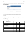
Web Graphical User Interface (GUI) for ESMS . . . . . . . . . . . . . . . . . . . . . . . . . . 3-13
Using the Web GUI . . . . . . . . . . . . . . . . . . . . . . . . . . . . . . . . . . . . . . . . . . . . . . 3-13
Login . . . . . . . . . . . . . . . . . . . . . . . . . . . . . . . . . . . . . . . . . . . . . . . . . . . . . . . . . . . 3-13
Dashboard . . . . . . . . . . . . . . . . . . . . . . . . . . . . . . . . . . . . . . . . . . . . . . . . . . . . . . 3-14
Device Information . . . . . . . . . . . . . . . . . . . . . . . . . . . . . . . . . . . . . . . . . . . 3-15
Network Information. . . . . . . . . . . . . . . . . . . . . . . . . . . . . . . . . . . . . . . . . . 3-16
Sensor Monitoring . . . . . . . . . . . . . . . . . . . . . . . . . . . . . . . . . . . . . . . . . . . . 3-16
Event Logs. . . . . . . . . . . . . . . . . . . . . . . . . . . . . . . . . . . . . . . . . . . . . . . . . . . . 3-17
Server Information . . . . . . . . . . . . . . . . . . . . . . . . . . . . . . . . . . . . . . . . . . . . . . 3-17
FRU Information. . . . . . . . . . . . . . . . . . . . . . . . . . . . . . . . . . . . . . . . . . . . . . . . . 3-17
Server Component . . . . . . . . . . . . . . . . . . . . . . . . . . . . . . . . . . . . . . . . . . . . 3-19
IV
TABLE OF CONTENT
Server identify . . . . . . . . . . . . . . . . . . . . . . . . . . . . . . . . . . . . . . . . . . . . . . . . 3-20
BIOS POST Code . . . . . . . . . . . . . . . . . . . . . . . . . . . . . . . . . . . . . . . . . . . . . . 3-21
Server Health Group . . . . . . . . . . . . . . . . . . . . . . . . . . . . . . . . . . . . . . . . . . 3-21
Sensor Readings . . . . . . . . . . . . . . . . . . . . . . . . . . . . . . . . . . . . . . . . . . . . . . 3-22
Event Log. . . . . . . . . . . . . . . . . . . . . . . . . . . . . . . . . . . . . . . . . . . . . . . . . . . . . 3-24
Configuration Group . . . . . . . . . . . . . . . . . . . . . . . . . . . . . . . . . . . . . . . . . . . . 3-26
Active Directory. . . . . . . . . . . . . . . . . . . . . . . . . . . . . . . . . . . . . . . . . . . . . . . 3-27
DNS . . . . . . . . . . . . . . . . . . . . . . . . . . . . . . . . . . . . . . . . . . . . . . . . . . . . . . . . . . 3-29
LDAP/E-Directory . . . . . . . . . . . . . . . . . . . . . . . . . . . . . . . . . . . . . . . . . . . . . 3-32
Mouse Mode. . . . . . . . . . . . . . . . . . . . . . . . . . . . . . . . . . . . . . . . . . . . . . . . . . 3-34
Network . . . . . . . . . . . . . . . . . . . . . . . . . . . . . . . . . . . . . . . . . . . . . . . . . . . . . . 3-36
PEF . . . . . . . . . . . . . . . . . . . . . . . . . . . . . . . . . . . . . . . . . . . . . . . . . . . . . . . . . . . 3-38
RADIUS . . . . . . . . . . . . . . . . . . . . . . . . . . . . . . . . . . . . . . . . . . . . . . . . . . . . . . . 3-46
Remote Session . . . . . . . . . . . . . . . . . . . . . . . . . . . . . . . . . . . . . . . . . . . . . . . 3-47
SMTP . . . . . . . . . . . . . . . . . . . . . . . . . . . . . . . . . . . . . . . . . . . . . . . . . . . . . . . . . 3-48
SOL. . . . . . . . . . . . . . . . . . . . . . . . . . . . . . . . . . . . . . . . . . . . . . . . . . . . . . . . . . . 3-51
SSL . . . . . . . . . . . . . . . . . . . . . . . . . . . . . . . . . . . . . . . . . . . . . . . . . . . . . . . . . . . 3-51
User Management . . . . . . . . . . . . . . . . . . . . . . . . . . . . . . . . . . . . . . . . . . . . 3-55
Virtual Media . . . . . . . . . . . . . . . . . . . . . . . . . . . . . . . . . . . . . . . . . . . . . . . . . 3-59
SNMP . . . . . . . . . . . . . . . . . . . . . . . . . . . . . . . . . . . . . . . . . . . . . . . . . . . . . . . . . . . 3-60
UTC Timezone. . . . . . . . . . . . . . . . . . . . . . . . . . . . . . . . . . . . . . . . . . . . . . . . . . . 3-60
LAN Port Settings. . . . . . . . . . . . . . . . . . . . . . . . . . . . . . . . . . . . . . . . . . . . . . . . 3-61
Remote Control . . . . . . . . . . . . . . . . . . . . . . . . . . . . . . . . . . . . . . . . . . . . . . . . . 3-62
Console Redirection. . . . . . . . . . . . . . . . . . . . . . . . . . . . . . . . . . . . . . . . . . . 3-62
Server Power Control . . . . . . . . . . . . . . . . . . . . . . . . . . . . . . . . . . . . . . . . . 3-70
Maintenance Group . . . . . . . . . . . . . . . . . . . . . . . . . . . . . . . . . . . . . . . . . . . . . 3-70
BMC Firmware Update . . . . . . . . . . . . . . . . . . . . . . . . . . . . . . . . . . . . . . . . 3-71
BIOS Update . . . . . . . . . . . . . . . . . . . . . . . . . . . . . . . . . . . . . . . . . . . . . . . . . . 3-72
Preserve Configuration. . . . . . . . . . . . . . . . . . . . . . . . . . . . . . . . . . . . . . . . 3-72
Restore Factory Defaults . . . . . . . . . . . . . . . . . . . . . . . . . . . . . . . . . . . . . . 3-74
Log Out . . . . . . . . . . . . . . . . . . . . . . . . . . . . . . . . . . . . . . . . . . . . . . . . . . . . . . . . . 3-75
User Privilege . . . . . . . . . . . . . . . . . . . . . . . . . . . . . . . . . . . . . . . . . . . . . . . . . . . 3-75
V
TABLE OF CONTENT
Regulatory and Compliance Information
VI
CONVENTIONS
Conventions
Several different typographic conventions are used throughout this manual. Refer to the
following examples for common usage.
Bold type face denotes menu items, buttons and application names.
Italic type face denotes references to other sections, and the names of the folders, menus,
programs, and files.
<Enter> type face denotes keyboard keys.
.Warning information appears before the text it references and should not be ignored as
the content may prevent damage to the device.
!
!
WARNING!
Warning information appears before the text it references and should not be ignored as the
content may prevent damage to the device.
CAUTION!
CAUTIONS APPEAR BEFORE THE TEXT IT REFERENCES, SIMILAR TO NOTES AND WARNINGS. CAUTIONS, HOWEVER,
APPEAR IN CAPITAL LETTERS AND CONTAIN VITAL HEALTH AND SAFETY INFORMATION.
Note:
Highlights general or useful information and tips.
VII
PRECAUTIONARY MEASURES
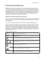
Precautionary Measures
Read all caution and safety statements in this document before performing any of the
instructions. To reduce the risk of bodily injury, electrical shock, fire, and equipment damage, read and observe all warnings and precautions in this chapter before installing or
maintaining your system. To avoid personal injury or property damage, before you begin
installing the product, read, observe, and adhere to all of the following instructions and
information. The following symbols may be used throughout this guide and may be
marked on the product and / or the product packaging.
Safety Instructions about your system
In the event of a conflict between the information in this guide and information provided
with the product or on the website for a particular product, the product documentation
takes precedence.
Your system should be integrated and serviced only by technically qualified persons.
You must adhere to the guidelines in this guide and the assembly instructions in related
chapters to ensure and maintain compliance with existing product certifications and
approvals. Use only the described, regulated components specified in this guide. Use of
other products / components will void the UL Listing and other regulatory approvals of
the product, and may result in noncompliance with product regulations in the region(s) in
which the product is sold.
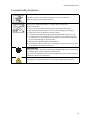
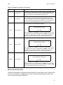
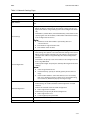
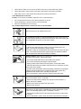
Table 1: Warning and Cautions
CAUTION
Indicates the presence of a hazard that may cause minor personal injury or property damage if the CAUTION is ignored.
WARNING
Indicates the presence of a hazard that may result in serious personal injury if the
WARNING is ignored.
Indicates potential hazard if indicated information is ignored.
Indicates shock hazards that result in serious injury or death if safety instructions
are not followed.
Indicates hot components or surfaces.
Indicates do not touch fan blades, may result in injury.
Remove the system from the rack to disconnect power system.
VIII
PRECAUTIONARY MEASURES
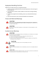
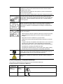
Table 1: Warning and Cautions (Continued)
The enclosure is designed to carry only the weight of the system sled. Do not use
this equipment as a workspace. Do not place additional load onto any equipment
in this system.
Indicates two people are required to safely handle the system.
Restricted Access Location: The system is intended for installation only in a
Server Room or Computer Room where both these conditions apply:
access can only be gained by SERVICE PERSONS or by USERS who have been
instructed about the reasons for the restrictions applied to the location and
about any precautions that shall be taken; and
access is through the use of a TOOL or lock and key, or other means of security,
and is controlled by the authority responsible for the location.
Intended Application Uses
This product was evaluated as Information Technology Equipment (ITE), which may be
installed in offices, schools, computer rooms, and similar commercial type locations. The
suitability of this product for other product categories and environments (such as medical,
industrial, residential, alarm systems, and test equipment), other than an ITE application,
may require further evaluation.
Site Selection
The system is designed to operate in a typical office environment. Choose a site that is:
Clean, dry, and free of airborne particles (other than normal room dust).
Well-ventilated and away from sources of heat including direct sunlight and radiators.
Away from sources of vibration or physical shock.
Isolated from strong electromagnetic fields produced by electrical devices.
In regions that are susceptible to electrical storms, we recommend you plug your
system into a surge suppressor and disconnect telecommunication lines to your
modem during an electrical storm.
Provided with a properly grounded wall outlet.
Provided with sufficient space to access the power system, because they serve as the
product's main power disconnect.
Provided with either two independent DC power system or two independent phases
from a single power system.
IX
PRECAUTIONARY MEASURES
Equipment Handling Practices
Reduce the risk of personal injury or equipment damage:
Conform to local occupational health and safety requirements when moving and
lifting equipment.
Use mechanical assistance or other suitable assistance when moving and lifting
equipment.
To reduce the weight for easier handling, remove any easily detachable components.
Never lift or move your system soley by the handle on the component.
Power and Electrical Warnings
!
!
CAUTION!
MAKE SURE THE SYSTEM IS REMOVED FROM THE RACK BEFORE SERVICING ANY NON-HOT PLUG COMPONENTS.
THE BUS BAR CLIPS MUST BE DISCONNECTED FROM THE POWER SYSTEM INORDER TO FULLY SEPARATE THE SYSTEM FROM THE POWER SOURCE.
CAUTION!
TO AVOID RISK OF ELECTRIC SHOCK, DISCONNECT ALL CABLING FROM THE SYSTEM AND REMOVE THE SYSTEM
FROM THE RACK.
System Access Warnings
!
CAUTION!
TO AVOID PERSONAL INJURY OR PROPERTY DAMAGE, THE FOLLOWING SAFETY INSTRUCTIONS APPLY WHENEVER
ACCESSING THE INSIDE OF THE PRODUCT:
Disconnect from the power source by removing the system from the rack.
Disconnect all cabling running into the system.
Retain all screws or other fasteners when servicing. Upon completion servicing, sercure
with original screws or fasteners.
CAUTION!
!
IF THE SERVER HAS BEEN RUNNING, ANY INSTALLED HDD MODULES MAY BE HOT.
!
!
CAUTION!
UNLESS YOU ARE ADDING OR REMOVING A HOT-PLUG COMPONENT, ALLOW THE SYSTEM TO COOL BEFORE SERVICING.
CAUTION!
TO AVOID INJURY DO NOT CONTACT MOVING FAN BLADES. IF YOUR SYSTEM IS SUPPLIED WITH A GUARD OVER THE
FAN, DO NOT OPERATE THE SYSTEM WITHOUT THE FAN GUARD IN PLACE.
X
PRECAUTIONARY MEASURES
Rack Mount Warnings
The following installation guidelines are required by UL for maintaining safety compliance
when installing your system into a rack.
The equipment rack must be anchored to an unmovable support to prevent it from tipping when your system or piece of equipment is extended from it. The equipment rack
must be installed according to the rack manufacturer's instructions.
Install equipment in the rack from the bottom up, with the heaviest equipment at the bottom of the rack.
Extend only one piece of equipment from the rack at a time.
You are responsible for installing a main power disconnect for the entire rack unit. This
main disconnect must be readily accessible, and it must be labeled as controlling power to
the entire unit, not just to the system(s).
To avoid risk of potential electric shock, a proper safety ground must be implemented for
the rack and each piece of equipment installed in it.
Elevated Operating Ambient - If installed in a closed or multi-unit rack assembly, the operating ambient temperature of the rack environment may be greater than room ambient.
Therefore, consideration should be given to installing the equipment in an environment
compatible with the maximum ambient temperature (Tma) specified by the manufacturer.
Reduced Air Flow - Installation of the equipment in a rack should be such that the amount
of air flow required for safe operation of the equipment is not compromised.
Mechanical Loading - Mounting of the equipment in the rack should be such that a hazardous condition is not achieved due to uneven mechanical loading.
Circuit Overloading - Consideration should be given to the connection of the equipment
to the supply circuit and the effect that overloading of the circuits might have on over-current protection and supply wiring. Appropriate consideration of equipment nameplate
ratings should be used when addressing this concern.
Reliable Earthing - Reliable earthing of rack-mounted equipment should be maintained.
Particular attention should be given to supply connections other than direct connections
to the branch circuit (e.g. use of power strips).
XI
PRECAUTIONARY MEASURES
Electrostatic Discharge (ESD)
!
CAUTION!
ESD CAN DAMAGE DRIVES, BOARDS, AND OTHER PARTS. WE RECOMMEND THAT YOU PERFORM ALL PROCEDURES
AT AN ESD WORKSTATION. IF ONE IS NOT AVAILABLE, PROVIDE SOME ESD PROTECTION BY WEARING AN ANTISTATIC WRIST STRAP ATTACHED TO CHASSIS GROUND -- ANY UNPAINTED METAL SURFACE -- ON YOUR SERVER
WHEN HANDLING PARTS.
Always handle boards carefully. They can be extremely sensitive to ESD. Hold boards only
by their edges without any component and pin touching. After removing a board from its
protective wrapper or from the system, place the board component side up on a
grounded, static free surface. Use a conductive foam pad if available but not the board
wrapper. Do not slide board over any surface.
Cooling and Airflow
!
CAUTION!
CAREFULLY ROUTE CABLES AS DIRECTED TO MINIMIZE AIRFLOW BLOCKAGE AND COOLING PROBLEMS. FOR
PROPER COOLING AND AIRFLOW, OPERATE THE SYSTEM ONLY WITH THE CHASSIS COVERS* / AIR DUCT INSTALLED.
OPERATING THE SYSTEM WITHOUT THE COVERS / AIR DUCT IN PLACE CAN DAMAGE SYSTEM PARTS . TO INSTALL
THE COVERS* / AIR DUCT:
Check first to make sure you have not left loose tools or parts inside the system.
Check that cables, add-in cards, and other components are properly installed.
Attach the covers* / air duct to the chassis according to the product instructions.
* May not apply to all systems.
Please be aware that slots and openings on the front and rear side of the chassis are
designed for ventilation; to make sure reliable operation of your system and to protect it
from overheating, these openings must not be covered or blocked. The openings should
never be covered or blocked by placing the product on a bed, sofa, rug, or other similar
surface. This product should never be placed near or over a radiator or heat register, or in a
built-in installation unless proper ventilation is provided.
Laser Peripherals or Devices
!
CAUTION!
TO AVOID RISK OF RADIATION EXPOSURE AND / OR PERSONAL INJURY:
Do not open the enclosure of any laser peripheral or device.
Laser peripherals or devices are not serviceable.
Return to manufacturer for servicing.
Use certified and rated Laser Class I for Optical Transceiver product.
Heed safety instructions: Before working with the system, whether using this manual or
any other resource as a reference, pay close attention to the safety instructions. Adhere to
the assembly instructions in this manual to ensure and maintain compliance with existing
product certifications and approvals. Use only the described, regulated components spec-
XII
PRECAUTIONARY MEASURES
ified in this manual. Use of other products / components will void the UL listing and other
regulatory approvals of the product and will most likely result in non-compliance with
product regulations in the region(s) in which the product is sold.
System power on/off: To remove power from system, you must remove the system from
rack. Make sure the system is removed from the rack before opening the chassis, adding,
or removing any non hot-plug components.
Hazardous conditions, devices and cables: Hazardous electrical conditions may be
present on power, telephone, and communication cables. Turn off the system and disconnect the cables attached to the system before opening it. Otherwise, personal injury or
equipment damage can result.
Electrostatic discharge (ESD) and ESD protection: ESD can damage drives, boards, and
other parts. We recommend that you perform all procedures in this chapter only at an ESD
workstation. If one is not available, provide some ESD protection by wearing an antistatic
wrist strap attached to chassis ground any unpainted metal surface on the server when
handling parts.
ESD and handling boards: Always handle boards carefully. They can be extremely sensitive to electrostatic discharge (ESD). Hold boards only by their edges. After removing a
board from its protective wrapper or from the server, place the board component side up
on a grounded, static free surface. Use a conductive foam pad if available but not the
board wrapper. Do not slide board over any surface.
Installing or removing jumpers: A jumper is a small plastic encased conductor that slips
over two jumper pins. Some jumpers have a small tab on top that can be gripped with fingertips or with a pair of fine needle nosed pliers. If the jumpers do not have such a tab,
take care when using needle nosed pliers to remove or install a jumper; grip the narrow
sides of the jumper with the pliers, never the wide sides. Gripping the wide sides can damage the contacts inside the jumper, causing intermittent problems with the function controlled by that jumper. Take care to grip with, but not squeeze, the pliers or other tool used
to remove a jumper, or the pins on the board may bend or break.
General Information
The information about rack and the wording “rack” in this technical guide supports the
organization of Open Compute definition.
The term Rack as found in this technical guide referes to the term Rack or Open Rack as
described and used in the Open Compute Project definition.
Before servicing this system, it is recommened to read this technical guide completely to
be aware of any safety issues or requirements involved in the servicing of this system.
XIII
PRECAUTIONARY MEASURES
Assembly Safety Guidelines
The power system in this product contains no user-serviceable parts.
Refer servicing only to qualified personnel.
The system is designed to operate in a typical office environment.
Choose a site that is:
Clean and free of airborne particles (other than normal room dust).
Well ventilated and away from sources of heat including direct sunlight.
Away from sources of vibration or physical shock.
Isolated from strong electromagnetic fields produced by electrical devices.
In regions that are susceptible to electrical storms, we recommend you plug
your system into a surge suppressor and disconnect telecommunication lines
to your modem during an electrical storm.
Provided with a properly grounded wall outlet.
Provided with sufficient space to access the power system, because they serve
as the product's main power disconnect.
WARNING!
The system is safety certified as rack-mounted equipment for use in a server room
or computer room, using an approved customer rack.
The enclosure is designed to carry only the weight of the system sled. Do not place
additional load onto any equipment.
Heavy object. Indicates two people are required to safely handle the system.
XIV
PRECAUTIONARY MEASURES
Structure of this guide
Chapter 1: About the System
“This section introduces the system, its different configuration(s) and the main
features.”
Chapter 2: BIOS
“This section provides information regarding the BIOS architecture, BIOS update
utility, server management, checkpoints, and error handling found in the system.”
Chapter 3: BMC
“This section provides information and key features of BMC (Baseboard Management Controller).”
Chapter 4: Regulatory and Compliance Information
“This section provides regulatory and compliance information applicable to this
system.”
XV
About the System
Chapter 1
This section introduces the system, its different configuration(s) and the main features.
ABOUT THE SYSTEM
INTRODUCTION
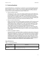
1.1 Introduction
QuantaGrid D51BP-1U is a revolutionary 1U rackmount server that dramatically increases
data storage IOPS. All ten 2.5” front-access drive bays support hot-pluggable SATA/SAS/
PCIe I/O interface. Owners can tailor system storage architecture by mixing traditional
hard disk drives and Non-Volatile Memory Express (NVMe) SSD.
Greener and More Powerful
Powered by Intel® Xeon® processor E5-2600 v3 product family and the DDR4 memory technology, it allows owners to upgrade computing performance without compromising power consumption. Also with QCT’s enhanced thermal and power
design, the server can operate under 35˚C ambient temperature without throttling
even if a fan rotor fails. This allows you to save unnecessary datacenter cooling cost
and achieve higher DCIE (Data center infrastructure efficiency) value.
Ultra Low Latency NVMe Solution
NVMe is an innovative host controller interface specification for SSDs to be accessed
through the PCIe bus. The data bandwidth increases to five times the traditional
SATAIII interface (6Gb/s compared with 31.5Gb/s of PCIe3.0x4), and the new interface significantly reduces the latency caused by register access. This solution efficiently supports multi-core architectures and SR-IOV for data-intensive
virtualization workloads. On QuantaGrid D51BP-1U, all ten 2.5” front-access drive
bays support hot-pluggable SATA/SAS/PCIe I/O interface. Owners can combine traditional hard disk drives and NVMe-based SSDs to tailor system storage architecture
to their needs.
Flexible and Scalable I/O options
QuantaGrid D51BP-1U provides flexible I/O scalability for today’s diverse data center
application requirements. It features OCP LAN mezzanine card solutions in addition
to dual GbE or 10GbE LAN on motherboards (LoM). With various controller vendors
and different speed and technology options, customers can choose from 1GbE to
56GbE bandwidth, copper or fiber-optic cabling, basic Ethernet function or FCoE
and ISCSI SAN connectivity. The onboard SAS controller offers multiple Quanta SAS
mezzanine card options with different RAID levels and data transfer bandwidth so
customers can tailor the SAS controller for specific application needs.
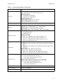
Specifications
Table 1.1: System Specifications
SPECIFICATIONS
DESCRIPTION
Form factor
1U rack mount
Dimensions
W x H x D (inch): 17.244 x 10.97 x 29.21
W x H x D (mm): 438 x 43.2 x 742
1-1
ABOUT THE SYSTEM
INTRODUCTION
Table 1.1: System Specifications (Continued)
SPECIFICATIONS
DESCRIPTION
Processor type:
Processor
Intel® Xeon® processor E5-2600 v3 product family
Max. TDP support:
145W with limited HDD Qty
135W with max configuration
Number of processors: 2
Internal Interconnect: 6.4 / 8.0 / 9.6 GT/s
Last Level Cache (LLC): Up to 45 MB
Chipset
Intel® C610
Memory
Total slots: 20
Capacity: Up to 640GB RDIMM / Up to 1280GB LRDIMM
Memory type: 2133 MHz DDR4 RDIMM / LRDIMM
Memory size: 32GB, 16 GB, 8 GB RDIMM / 64GB, 32 GB LRDIMM
Storage controller
Onboard (Intel® C610):
10x SATA 6Gb/s ports
SATA RAID 0, 1, 10
Optional controller:
Quanta LSI® 2308 6Gb/s SAS mezzanine, RAID 0, 1, 10
Quanta LSI® 3008 12Gb/s SAS mezzanine, RAID 0, 1, 10
Quanta LSI® 2208 6Gb/s RAID mezzanine, RAID 0, 1, 5, 10;
RAID 6 with additional RAID key
Networking
LOM:
Option 1: Intel® I350 dual-port 1 GbE, Dedicated 1 GbE management
port
Option 2: Intel® X540 dual-port 10 G BASE-T, Dedicated 1 GbE management port
Optional NIC: (more options refer to the CCL)
Quanta Intel® I350 dual-port OCP mezzanine
Quanta Intel® X540 dual-port 10 G BASE-T OCP mezzanine
Quanta Intel® 82599ES dual-port 10G SFP+ OCP mezzanine
Expansion slots
Option 1 (default):
One x8 PCIe 3.0 SAS mezzanine slot
One x8 PCIe 3.0 OCP LAN mezzanine slot
Two x8 PCIe 3.0, LP MD-2
Option 2 (this sku does not support any 2.5" PCIe SSD):
One x8 PCIe 3.0 SAS mezzanine slot
One x8 PCIe 3.0 OCP LAN mezzanine slot
Two x16 PCIe 3.0, LP MD-2
Storage
10x 2.5" hot-plug (support SATA / SAS/ PCIe-based interface)
Onboard storage
Support 2x SATADOM
Video
Integrated Aspeed AST2400 with 8MB DDR3 video memory
1-2
ABOUT THE SYSTEM
INTRODUCTION
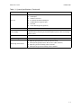
Table 1.1: System Specifications (Continued)
SPECIFICATIONS
DESCRIPTION
Rear I/O
2x USB 3.0 ports
1x VGA port
1x RS232 serial Port
2x 1 GbE or 10G BASE-T RJ45 port
1x GbE RJ45 management port
1x ID LED
1x Port 80 Debug Port (optional)
TPM
Yes (optional)
Power supply
1+1 High efficiency redundant hot-plug PSU
(default with one PSU only; detailed PSU options please refer to "ordering
info" or "CCL")
Fan
6x dual rotor fans (11+1 redundant)
System management
IPMI v2.0 Compliant, on board "KVM over IP" support
Operating environment
Operating temperature: 5°C to 35°C (41°F to 95°F)
Non-operating temperature: -40°C to 65°C (-40°F to 149°F)
Operating relative humidity: 50% to 85%RH
Non-operating relative humidity: 20% to 90%RH
1-3
ABOUT YOUR SYSTEM
PACKAGE CONTENTS
1.2 Package Contents
(1) D51BP-1U system
(2) processor heat sinks
(1) power supply unit
(1) power cord (optional)
(1) utility CD (User’s Guide included)
(1) rail kit
Note:
Note: For exact shipping contents, contact your Quanta sales representative.
1-4
ABOUT THE SYSTEM
A TOUR OF THE SYSTEM
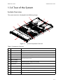
1.3 A Tour of the System
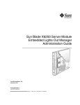
System Overview
The system overview is displayed in the following image:
3
4
2
5
1
11
6
7
8
10
9
Figure 1-1.
System Component Overview
Table 2: Component Overview
NO.
ITEM
DESCRIPTION
1
Fan module
(6) System fan modules
2
DIMM slots
(10) DDR4 DIMM slots
3
PSU assembly
Redundant power supply unit assembly
4
Riser assembly
5
Riser assembly
6
PSU assembly
Redundant power supply unit assembly
7
Mainboard
System mainboard
8
Backup battery
Backup battery for mezzanine card
9
Front control panel
See Front Control Panel on page 1-6
10
HDD assembly
10 x 2.5” storage device assemblies
11
Mid-Top cover
Houses the chassis and secure the top cover
Up to two x8 PCIe slots
1-5
ABOUT THE SYSTEM
SYSTEM FRONT VIEW
Note:
The system features one standard PCIe Riser Assembly supporting standard PCIe cards (see
item 4 in previous illustration) and one low profile PCIe riser assembly (available in certain
models) supporting low profile PCIe cards (see item 5 in previous illustration).
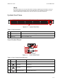
System Front View
2
1
Figure 1-2. System Front View
Table 3: Front Panel View
NO.
NAME
DESCRIPTION
1
Front control panel
See Front Control Panel LED on page 1-9 for further information.
2
HDD bays
10 x2.5” SAS HDD / SSD
Front Control Panel
6
7
5
4
3
2
1
8
Figure 1-3.
Front Control Panel
Table 4: Front Control Panel Definition
NO.
ICON
NAME
DESCRIPTION
1
Reset button
Soft reset system function
2
LAN2 LED
LAN access
3
LAN1 LED
LAN access
4
HDD activity LED
Hard disk drive access
1-6
ABOUT THE SYSTEM
SYSTEM REAR VIEW
Table 4: Front Control Panel Definition (Continued)
NO.
ICON
NAME
DESCRIPTION
5
Fault LED
Provides critical and non-critical failure notification
6
Identification LED
Activate ID LED to identify system
7
ID button
Toggles ID LED
8
Power button
Power on / off
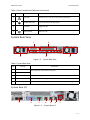
System Rear View
1
2
5
4
Figure 1-4.
3
System Rear View
Table 5: System Rear View
NO.
FEATURE
DESCRIPTION
1
Expansion slot
2
Expansion slot
3
Power sub-system
Main power supply unit (PSU1). See Power Sub-System on page 1-8.
4
System I/O ports
See System Rear I/O on page 1-7
5
Power sub-system
Secondary power supply unit (PSU2). See Power Sub-System on page 1-8
PCIe expansion slot with PCIe x8 signal
System Rear I/O
1
2
3
4
5
6
7
Figure 1-5. System Rear I/O
1-7
ABOUT THE SYSTEM
SYSTEM REAR VIEW
Table 6: System Rear I/O Defintition
NO.
ICON
NAME
DESCRIPTION
1
OCP connector
OCP debug connector (optional)
2
VGA connector
Maximum display resolution: 1920x1200 32bpp@60Hz
(reduced blanking)
3
COM port A
DB9 port (Serial_A) for debug or terminal concentrator
4
NIC2
RJ45 connector
5
NIC1
RJ45 connector
6
Dedicated NIC
Dedicated RJ45 connector
7
USB ports
USB ports (2.0 / 3.0)
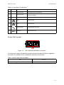
Power Sub-System
PSU
Figure 1-6. PSU to Mainboard Module Description
A single power supply unit (default) and power distribution board (PDB) are supplied in
the system. A secondary PSU is available for redundacy functionality.
Table 7: Power Supply Units by Model
PSU
AC INPUT
2 x 750W high efficiency redundant PSU
100-240V AC 50/60Hz
1-8
ABOUT THE SYSTEM
LED STATUS DEFINITIONS
LED Status Definitions
Front Control Panel LED
For further information and location of the FCP LEDs, see Front Control Panel LED on
page 1-9.
Figure 1-7. Front Control Panel LEDs
Table 8: Front Control Panel LED Behavior
NAME
COLOR
Power LED
Blue
Identification
Blue
CONDITION
DESCRIPTION
On
System power on
Off
System power off
On
Unit selected for identification
Off
No identification request
Critical Failure: critical fan, voltage, temperature state.
Blinking
Fault LED
Amber
Off
HDD activity
Blue
LAN1 LED
Blue
LAN2 LED
Blue
Non-Critical Failure: non-critical fan, voltage, temperature
state, CPU thermal trip, DC off.
SEL cleared
Last pending warning or error has been de-asserted.
Blinking
Hard disk drive access (only on board SATA port)
Off
No access (non-SAS)
On
Link
Blinking
LAN access (off when there is traffic)
On
Link
Blinking
LAN access (off when there is traffic)
1-9
ABOUT THE SYSTEM
LED STATUS DEFINITIONS
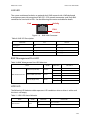
LAN LED
The system mainboard includes an optional dual 1GbE network with 1GbE dedicated
management port with an optional 10G SPF+ OCP network mezzanine card. Each RJ45
connector has two built-in LEDs. See the following illustration and table for details.
Activity
Link
PIN 1
Location
Figure 1-8. RJ45 LAN Connector
Table 9: RJ45 LED Description
CONDITION
LINK
ACTIVITY
Unplugged
Off
Off
1G active link
On amber
Blinking green
100M active link
On green
Blinking green
10M active link
Off
Blinking green
BMC Management Port LED
Table 10: BMC Management Port LED Behaviour
NAME
BMC Dedicated LAN
COLOR
Speed 1G (Left LED)
Amber
Speed 100M (Left LED)
Green
Activity (Right LED)
Green
CONDITION
BEHAVIOUR
ON
LAN link
OFF
No link
ON
LAN link
OFF
No link
Blinking
LAN Access
OFF
Disconnected
HDD LED
The following LED behavior table represents LED conditions when a driver is online and
the slot is not empty.
Table 11: HDD LED Status Behavior
NAME
HDD Status*
COLOR
Blue
CONDITION
DESCRIPTION
On
Drive is online
Off
Slot is empty
1-10
ABOUT THE SYSTEM
LED STATUS DEFINITIONS
Table 11: HDD LED Status Behavior (Continued)
NAME
COLOR
HDD Activity
Blue
HDD Fault
Amber
CONDITION
DESCRIPTION
On
HDD access is active
Off
No access
On
HDD failure
Off
No failure detected
* Only support SATA/SAS HDD/SSD.
1-11
BIOS
Chapter 2
This section provides information regarding the BIOS architecture, BIOS update utility,
server management, checkpoints, and error handling found in the system.
BIOS
BIOS SETUP UTILITY
2.1 BIOS Setup Utility
The BIOS Setup utility is provided to perform system configuration changes and to display
current settings and environment information.
The BIOS Setup utility stores configuration settings in system non-volatile storage.
Changes affected by BIOS Setup will not take effect until the system is rebooted. The BIOS
Setup Utility can be accessed during POST by using the <DEL> or <F2> key.
The following sections describe the look and behavior for platform Setup.
Operation
BIOS Setup has the following features:
The server board BIOS will only be available in English.
BIOS Setup is functional via console redirection over various terminal emulation
standards. This may limit some functionality for compatibility, e.g., usage of colors,
some keys or key sequences, or support of pointing devices.
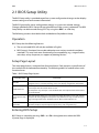
Setup Page Layout
The setup page layout is sectioned into functional areas. Each occupies a specific area of
the screen and has dedicated functionality. The following table lists and describes each
functional area.
Table 1: BIOS Setup Page Layout
FUNCTIONAL AREA
DESCRIPTION
Title Bar
The title bar is located at the top of the screen and displays the title of the form
(page) the user is currently viewing. It may also display navigational information.
Setup Item List
The Setup Item List is a set of controllable and informational items. Each item in the
list occupies the left column of the screen.
A Setup Item may also open a new window with more options for that functionality on the board.
Item Specific Help
Area
The Item Specific Help area is located on the right side of the screen and contains
help text for the highlighted Setup Item. Help information may include the meaning and usage of the item, allowable values, effects of the options, etc.
Keyboard Command Bar
The Keyboard Command Bar is located at the bottom right of the screen and continuously displays help for keyboard special keys and navigation keys.
Entering BIOS Setup
BIOS Setup is started by pressing <DEL> or <F2> during boot time when the OEM
(Quanta) logo is displayed.
2-1
BIOS
KEYBOARD COMMANDS
When Quiet Boot is disabled, the message “press <DEL> or <F2> to enter setup” will be
displayed on the diagnostics screen.
Keyboard Commands
The bottom right portion of the Setup screen provides a list of commands that are used to
navigate through the Setup utility. These commands are displayed at all times.
Each Setup menu page contains a number of features. Except those used for informative
purposes, each feature is associated with a value field. This field contains user-selectable
parameters. Depending on the security option chosen and in effect by the password, a
menu feature's value may or may not be changeable. If a value is non-changeable, the feature's value field is inaccessible and displays as "grayed out."
Table 2: Keyboard Commands
KEY
OPTION
DESCRIPTION
Execute Command
The <Enter> key is used to activate sub-menus when the selected
feature is a sub-menu, or to display a pick list if a selected option has
a value field, or to select a sub-field for multi-valued features like time
and date. If a pick list is displayed, the <Enter> key will select the currently highlighted item, undo the pick list, and return the focus to the
parent menu.
Exit
The <Esc> key provides a mechanism for backing out of any field.
When the <Esc> key is pressed while editing any field or selecting
features of a menu, the parent menu is re-entered.
When the <Esc> key is pressed in any sub-menu, the parent menu is
re-entered. When the <Esc> key is pressed in any major menu, the
exit confirmation window is displayed and the user is asked whether
changes can be discarded. If “No” is selected and the <Enter> key is
pressed, or if the <Esc> key is pressed, the screen is returned to the
one before pressing the <Esc> key, without affecting any existing
any settings. If “Yes” is selected and the <Enter> key is pressed, setup
is exited and the BIOS returns to the main System Options Menu
screen.
↑
Select Item
The up arrow is used to select the previous value in a pick list, or the
previous option in a menu item's option list. The selected item must
then be activated by pressing the <Enter> key.
↓
Select Item
The down arrow is used to select the next value in a menu item's
option list, or a value field's pick list. The selected item must then be
activated by pressing the <Enter> key.
←→
Select Menu
The left and right arrow keys are used to move between the major
menu pages. The keys have no affect if a sub-menu or pick list is displayed.
<Tab>
Select Field
The <Tab> key is used to move between fields. For example, <Tab>
can be used to move from hours to minutes in the time item in the
main menu.
<Enter>
<Esc>
2-2
BIOS
MENU SELECTION BAR
Table 2: Keyboard Commands (Continued)
KEY
-
+
OPTION
DESCRIPTION
Change Value
The minus key on the keypad is used to change the value of the current item to the previous value. This key scrolls through the values in
the associated pick list without displaying the full list.
Change Value
The plus key on the keypad is used to change the value of the current
menu item to the next value. This key scrolls through the values in
the associated pick list without displaying the full list. On 106-key
Japanese keyboards, the plus key has a different scan code than the
plus key on the other keyboard, but will have the same effect.
Pressing <F8> causes the following to appear:
Load Optimized Defaults?
<F8>
Previous Values
Yes No
If Yes is highlighted and <Enter> is pressed, all Setup fields are set to
their previous values. If No is highlighted and <Enter> is pressed, or if
the <Esc> key is pressed, the screen is returned to the one before
<F8> was pressed without affecting any existing field values
Pressing <F9> causes the following to appear:
Load Optimized Defaults?
<F9>
Setup Defaults
Yes No
If Yes is highlighted and <Enter> is pressed, all Setup fields are set to
their default values. If No is highlighted and <Enter> is pressed, or if
the <Esc> key is pressed, the screen is returned to the one before
<F9> was pressed without affecting any existing field values
Pressing <F10> causes the following message to appear:
Save configuration and Reset?
<F10>
Save and Reset
Yes No
If Yes is highlighted and <Enter> is pressed, all changes are saved
and system resets. If No is highlighted and <Enter> is pressed, or the
<Esc> key is pressed, the screen is returned to the one before <F10>
was pressed without affecting any existing values.
Menu Selection Bar
The Menu Selection Bar is located at the top of the BIOS Setup Utility screen. It displays the
major menu selections available to the user. By using the left and right arrow keys, the
user can select the menus listed here.
2-3
BIOS
SERVER PLATFORM SETUP UTILITY SCREENS
Server Platform Setup Utility Screens
The sections below describe the screens available for the configuration of a server platform. In these sections, tables are used to describe the contents of each screen. These
tables follow the following guidelines:
The text and values in the Setup Item, Options, and Help columns in the tables are
displayed on the BIOS Setup screens.
Bold text in the Options column of the tables indicates default values. These values
are not displayed in bold on the setup screen. The bold text in this document is to
serve as a reference point.
The Comments column provides additional information where it may be helpful.
This information does not appear in the BIOS Setup screens.
Information in the screen shots that is enclosed in brackets (< >) indicates text that
varies, depending on the option(s) installed. For example <Current Date> is replaced
by the actual current date.
Information that is enclosed in square brackets ([ ]) in the tables indicates areas
where the user needs to type in text instead of selecting from a provided option.
Whenever information is changed (except Date and Time) the systems requires a
save and reboot to take place. Pressing <ESC> will discard the changes and boot the
system according to the boot order set from the last boot.
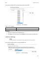
Main Screen
Figure 2-1.
Main Screen
2-4
BIOS
ADVANCED SCREEN
Table 3: Main Screen Description
SETUP ITEM
OPTIONS
HELP TEXT
COMMENTS
BIOS Vendor
Information only. Displays the
BIOS Vendor.
Core Version
Information only. Displays the
AMI BIOS Core version.
Compliancy
Information only. Displays the
BIOS compliancy.
Project Version
Information only. Displays the
Project version.
Build Date and
Time
Information only. Displays the
BIOS build date.
Total Memory
Information only. Displays the
Total System Memory Size.
System Date
[Day of week
MM/DD/YYYY]
Set the Date. Use Tab to switch
between Date elements.
System Time
[HH:MM:SS]
Set the Time. Use Tab to switch
between Time elements.
Access Level
Information only. Displays the
Access Level.
Advanced Screen
The Advanced screen provides an access point to configure several options. On this
screen, the user selects the option that is to be configured. Configurations are performed
on the selected screen, not directly on the Advanced screen.
2-5
BIOS
ADVANCED SCREEN
To access this screen from the Main screen, press the right arrow until the Advanced
screen is chosen.
Figure 2-2. Advanced Screen
Table 4: Advanced Screen Description
SETUP ITEM
OPTIONS
HELP TEXT
Super IO Configuration
System Super IO Chip Parameters.
SATA Configuration
SATA Devices Configuration set.
Serial Port Console Redirection
Serial Port Console Redirection
Onboard Device
Configuration
Onboard Device Parameters
PCI Subsystem
Settings
PCI, PCI-X and PCI Express Settings.
CSM Configuration
CSM configuration: Enable/Disable, Option ROM execution settings, etc.
Trusted Computing
Trusted Computing Settings
USB Configuration
USB Configuration Parameters
iSCSI Configuration
Configure the iSCSI Parameters
COMMENTS
Dynamic
2-6
BIOS
INTELRCSETUP SCREEN
IntelRCSetup Screen
The IntelRCSetup screen provides an access point to configure several options. On this
screen, the user selects the option that is to be configured. Configurations are performed
on the selected screen, not directly on the IntelRCSetup screen.
To access this screen from the Main screen, press the right arrow until the IntelRCSetup
screen is chosen.
Figure 2-3.
IntelRCSetup Screen
Table 5: IntelRCSetup Screen Description
SETUP ITEM
OPTIONS
HELP TEXT
[Custom]
[Energy-Saving]
[Balanced]
Pwr/Perf Profiles
[Virtualization]
[High Performance]
Configure your own power and
performance settings under Custom or adopt quick setting profiles.
Processor Configuration
Displays and provides option to
change the Processor Settings
Advanced Power
Management
Configuration
Displays and provides option to
change the Power Management
Settings
Common RefCode Configuration
Displays and provides option to
change the Common RefCode
Settings
QPI Configuration
Displays and provides option to
change the QPI Settings
COMMENTS
2-7
BIOS
SERVER MANAGEMENT SCREEN
Table 5: IntelRCSetup Screen Description (Continued)
SETUP ITEM
OPTIONS
HELP TEXT
Memory Configuration
Displays and provides option to
change the Memory Settings
IIO Configuration
Displays and provides option to
change the IIO Settings
PCH Configuration
Displays and provides option to
change the PCH Settings
Server ME Configuration
Configure Server ME Technology
Parameters
Runtime Error
Logging
Press <Enter> to view or change
the runtime error log configuration.
COMMENTS
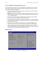
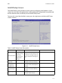
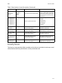
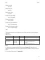
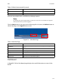
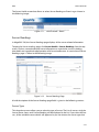
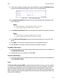
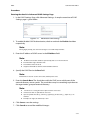
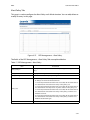
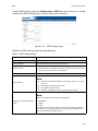
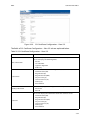
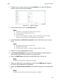
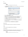
Server Management Screen
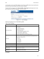
The Server Management screen displays information of the BMC, and allows the user to
configure desired settings.
To access this screen from the Main screen, select Server Mgmt Options.
Figure 2-4. Server Management Screen
Table 6: Server Management Screen Description
SETUP ITEM
BMC Self Test
Status
OPTIONS
HELP TEXT
COMMENTS
Information only. Displays the
BMC Self Test Status.
2-8
BIOS
SERVER MANAGEMENT SCREEN
Table 6: Server Management Screen Description (Continued)
SETUP ITEM
OPTIONS
HELP TEXT
COMMENTS
BMC firmware
version
Information only. Displays the
BMC firmware version.
IPMI version
Information only. Displays the
IPMI version.
FRB-2 Timer
[Disabled]
[Enabled]
Enable or Disable FRB-2 timer
(POST timer)
Not available if FRB2 Timer is disabled.
FRB-2 Timer
timeout
[3 minutes]
[4 minutes]
[5 minutes]
[6 minutes]
Enter value Between 3 to 6 min
for FRB-2 Timer Expiration value
Not available if FRB2 Timer is disabled.
FRB-2 Timer Policy
[Do Nothing]
[Reset]
[Power Down]
[Power Cycle]
Configure how the system
should respond if the FRB-2
Timer expires. Not available if
FRB-2 Timer is disabled.
OS Watchdog
Timer
[Disabled]
[Enabled]
If enabled, starts a BIOS timer
which can only be shut off by
Intel Management Software after
the OS loads. Helps determine
that the OS successfully loaded
or follows the OS Boot Watchdog
Timer policy.
OS Wtd Timer
Timeout
[5 minutes]
[10 minutes]
[15 minutes]
[20 minutes]
Configure the length of the OS
Boot Watchdog Timer. Not available if OS Boot Watchdog Timer
is disabled.
Not available if watchdog Timer
is disabled.
OS Wtd Timer
Policy
[Do Nothing]
[Reset]
[Power Down]
Configure how the system
should respond if the OS Boot
Watchdog Timer expires. Not
available if OS Boot Watchdog
Timer is disabled.
Not available if watchdog Timer
is disabled.
System Event
Log
Press <Enter> to change the SEL
event log configuration.
View FRU information
Press <Enter> to view FRU information.
BMC network
configuration
Configure BMC network parameters
Restore on AC
Power Loss
Current Restore
on AC Power
Loss
[Power Off ]
[Power On]
[Last State]
[No Change]
System action to take on AC
power loss
Information only. Displays current system action to take on AC
power loss.
2-9
BIOS
BOOT OPTIONS SCREEN
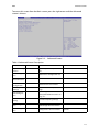
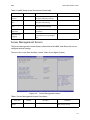
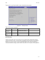
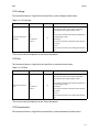
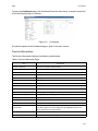
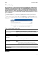
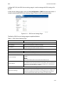
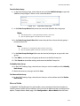
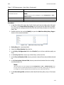
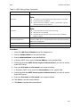
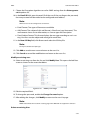
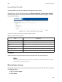
Boot Options Screen
The Boot Options screen displays any bootable media encountered during POST, and
allows the user to configure desired boot device.
If no boot devices are available – for example, both onboard LAN are disabled and no
bootable device connected when Boot Mode is set to Legacy – the system will auto boot
into BIOS setup menu.
To access this screen from the Main screen, select Boot Options.
Figure 2-5. Boot Options Screen
Table 7: Boot Options Screen Description
SETUP ITEM
OPTIONS
HELP TEXT
Setup Prompt
Timeout
[<number>]
Number of seconds to wait for
setup activation key.
Default is 5 seconds, max is 10
and min is 1.
Bootup NumLock State
[On]
[Off ]
Select the keyboard NumLock
state
POST Error
Pause
[Disabled]
[Enabled]
Enables or disables POST Error
Pause
Quiet Boot
[Disabled]
[Enabled]
Enables or disables Quiet Boot
option
COMMENTS
2-10
BIOS
SECURITY SCREEN
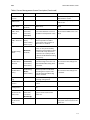
Table 7: Boot Options Screen Description (Continued)
SETUP ITEM
HELP TEXT
COMMENTS
Select boot mode LEGACY/UEFI
This item decides what devices
(Legacy or UEFI) BIOS should try
to boot when let the system auto
boot up without manually select
boot device.
Boot Option #1
Boot Option #2
Boot Option #3
Boot Option #4
Boot Option #5
Sets the system boot order
Default priority:
1st: USB
2nd: Network
3rd: Hard Disk
4th: CD/DVD
5th: Other
Hard Drive BBS
Priorities
Set the order of the legacy
devices in this group
Only appears when at least one
Hard Disk is detected.
Network Device
BBS Priorities
Set the order of the legacy
devices in this group
Only appears when at least one
Network Device is detected.
Hard Drive BBS
Priorities
Set the order of the legacy
devices in this group
Only appears when at least one
Hard Disk is detected.
CD/DVD ROM
Drive BBS Priorities
Set the order of the legacy
devices in this group
Only appears when at least one
CD/DVD Drive is detected.
Floppy Drive
BBS Priorities
Set the order of the legacy
devices in this group
Only appears when at least one
Floppy Device is detected.
Boot mode
select
OPTIONS
[LEGACY]
[UEFI]
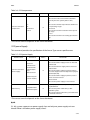
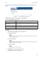
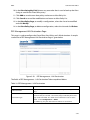
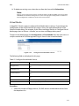
Security Screen
The Security screen provides fields to enable and set the user and administrative password
and to lockout the front panel buttons so they cannot be used.
2-11
BIOS
EXIT SCREEN
To access this screen from the Main screen, select the Security option.
Figure 2-6. Security Screen
Table 8: BIOS Screen Description
SETUP ITEM
OPTIONS
HELP TEXT
Administrator
Password
Set Administrator Password
User Password
Set User Password
Secure Boot
menu
Customizable Secure Boot settings
COMMENTS
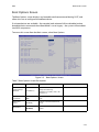
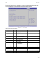
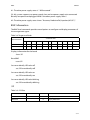
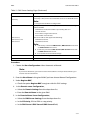
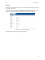
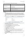
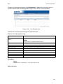
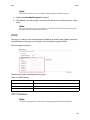
Exit Screen
The Exit screen allows the user to choose to save or discard the configuration changes
made on the other screens. It also provides a method to restore the server to the factory
defaults or to save or restore a set of user defined default values. If Restore Defaults is
selected, the default settings, noted in bold in the tables in this chapter, will be applied. If
2-12
BIOS
EXIT SCREEN
Restore User Default Values is selected, the system is restored to the default values that
the user saved earlier, instead of being restored to the factory defaults.
Figure 2-7.
Exit Screen
Table 9: Exit Screen Description
SETUP ITEM
OPTIONS
HELP TEXT
Discard Changes and
Exit
Exit system setup without saving
any changes.
Save Changes and
Reset
Reset the system after saving the
changes.
Discard Changes
Discards changes done so far to
any of the setup options.
Restore Defaults
Restore/Load Default values for
all the setup options.
Save as User Defaults
Save the changes done so far as
User Defaults.
Restore User Defaults
Restore the User Defaults to all
the setup options.
COMMENTS
[<Device String 1>]
Boot with Device <Device String 1>
[<Device String 2>]
Boot with Device <Device String 2>
[<Device String 3>]
Boot with Device <Device String 3>
[<Device String 4>]
Boot with Device <Device String 4>
[<Device String 5>]
Boot with Device <Device String 5>
[<Device String 6>]
Boot with Device <Device String 6>
2-13
BIOS
LOADING BIOS DEFAULTS
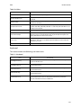
Loading BIOS Defaults
Different mechanisms exist for resetting the system configuration to the default values.
When a request to reset the system configuration is detected, the BIOS loads the default
system configuration values during the next POST. The request to reset the system to the
defaults can be sent in the following ways:
Pressing <F9> from within the BIOS Setup utility
Load BIOS defaults by jumper as follows:
1. Power down the system.
2. Move CMOS clear jumper from pins 1-2 to pins 2-3 for a few seconds.
3. Move CMOS clear jumper back to pins 1-2.
4. System automatically powers on.
5. Check BIOS defaults are loaded.
2-14
BIOS
BIOS UPDATE UTILITY
2.2 BIOS Update Utility
The flash ROM contains system initialization routines, the BIOS Setup Utility, and runtime
support routines. The exact layout is subject to change, as determined by BIOS. The flash
ROM also contains initialization code in compressed form for onboard peripherals, like
SCSI, NIC and video controllers. The complete ROM is visible, starting at physical address 4
GB minus the size of the flash ROM device.
A 16-KB parameter block in the flash ROM is dedicated to storing configuration data that
controls the system configuration (ESCD). Application software must use standard APIs to
access these areas; application software cannot access the data directly.
BIOS Update Utility
Server platforms support DOS-based, Windows-based, and Linux-based firmware update
utilities. It is very important to follow the rule, and use official provided package to update
BIOS under DOS/Linux/ EFI shell environment. Using incorrect flash option to flash BIOS
may cause damage to your system. This utility loads a fresh copy of the BIOS into the flash
ROM.
The BIOS update may affect the following items:
The system BIOS, including the setup utility and strings.
Onboard video BIOS, RAID BIOS, and other option ROMS for the devices embedded
on the server board.
Memory reference code.
Microcode updates.
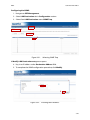
AFULNX: v2.39
1. Copy afulnx_26_64, BIOS BIN and Windmill batch file to installed linux OS, execute
biosupdate.sh under linux base environment and update finishes automatically.
2. Reboot system then new BIOS runs.
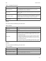
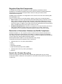
ME Region Update
Update utility also provide ME region update function, please refer to the README.txt that
each official release BIOS attached.
The BIOS update may affect the following items:
The system BIOS, including the setup utility and strings.
Onboard video BIOS, RAID BIOS, and other option ROMS for the devices embedded
on the server board.
Memory reference code.
2-15
BIOS
CLEAR CMOS
Microcode updates.
ME Firmware.
BIOS Setting Utility
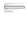
Use AMISCE to import/export BIOS setting in Linux:
1. Export BIOS setting and generate script file:
/o /s NVRAM.txt
2. Import BIOS setting with script file:
/i /s NVRAM.txt
BIOS Revision
The BIOS revision is used to identify the BIOS image and BIOS phase.
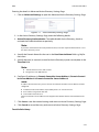
Clear CMOS
The following steps will load the BIOS defaults by jumper:
1. Power down the system.
2. Move CMOS clear jumper from pins 1-2 to pins 2-3 for a few seconds.
3. Move CMOS clear jumper back to pins 1-2.
4. System automatically powers on.
5. Check BIOS defaults are loaded.
Clear Password
1. Power down the system.
2. Move password clear jumper from pins 1-2 to pins 2-3.
3. Power on the system.
4. Make sure password is cleared.
5. Power down the system.
6. Move password clear jumper from pins 2-3 back to pins 1-2.
7. Power on the system.
8. Set new password.
2-16
BIOS
SERVER MANAGEMENT
2.3 Server Management
The BIOS supports many standard-based server management features and several proprietary features. The Intelligent Platform Management Interface (IPMI) is an industry standard and defines standardized, abstracted interfaces to platform management hardware.
The BIOS implements many proprietary features that are allowed by the IPMI specification,
but these features are outside the scope of the IPMI specification. This section describes
the implementation of the standard and proprietary features.
Console Redirection
The BIOS supports redirection of both video and keyboard via a serial link (serial port).
When console redirection is enabled, the local, or host server, keyboard input and video
output are passed both to the local keyboard and video connections, and to the remote
console through the serial link. Keyboard inputs from both sources are considered valid
and video is displayed to both outputs.
As an option, the system can be operated without a host keyboard or monitor attached to
the system and run entirely via the remote console. Utilities that can be executed remotely
include BIOS Setup.
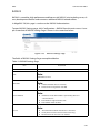
Serial Configuration Settings
The BIOS does not require that the splash logo be turned off for console redirection to
function. The BIOS supports multiple consoles, some of which are in graphics mode and
some in text mode. The graphics consoles can display the logo and the text consoles
receive the redirected text.
Keystroke Mapping
During console redirection, the remote terminal sends keystrokes to the local server. The
remote terminal can be a dumb terminal with a direct connection and running a communication program. The keystroke mapping follows VT-UTF8 format with the following
extensions.
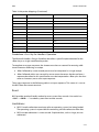
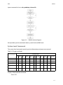
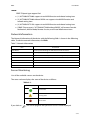
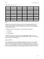
Table 10: Keystroke Mappings
KEY
ANSI ESCAPE SEQUENCE
WINDOWS PLATFORM DESIGN NOTE
F1
<ESC><Shift>op
<ESC>1
F2
<ESC><Shift>oq
<ESC>2
F3
<ESC><Shift>or
<ESC>3
F4
<ESC><Shift>os
<ESC>4
F5
<ESC>5
F6
<ESC>6
F7
<ESC>7
2-17
BIOS
CONSOLE REDIRECTION
Table 10: Keystroke Mappings (Continued)
KEY
ANSI ESCAPE SEQUENCE
WINDOWS PLATFORM DESIGN NOTE
F8
<ESC>8
F9
<ESC>9
F10
<ESC>0
F11
<ESC>!
F12
<ESC>@
Home
<ESC>[<Shift>h
<ESC>h
End
<ESC>[<Shift>k
<ESC>k
Ins
<ESC>+
Del
<ESC>-
Page Up
<ESC>?
Page Down
<ESC>/
Reset
<ESC>R<ESC>r<ESC>R
Standalone <Esc> Key for Headless Operation
The Microsoft Headless Design Guidelines describes a specific implementation for the
<Esc> key as a single standalone keystroke:
To complete an escape sequence, the timeout must be two seconds for entering additional characters following an escape.
<Esc> followed by a two-second pause must be interpreted as a single escape.
<Esc> followed within two seconds by one or more characters that do not form a
sequence described in this specification must be interpreted as <Esc> plus the character or characters, not as an escape sequence.
The escape sequence in the following table is an input sequence. This means it is sent to
the BIOS from the remote terminal.
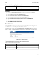
Reset
BIOS provides another friendly method to reset system from console. User could use
<Ctrl> + <Shift> + ‘-’ to reboot system from remote console.
Limitations
BIOS Console redirection terminates after an operating system has being loaded.
The operating system is responsible for continuing console redirection after that.
BIOS console redirection is a text console. Graphical data, such as a logo, are not
redirected.
2-18
BIOS
NETWORK BIOS SUPPORT
Interface to Server Management (Optional)
If the BIOS determines that console redirection is enabled, it will read the current baud
rate and pass this value to the appropriate management controller via the Intelligent Platform Management Bus (IPMB).
Network BIOS Support
PXE Boot
The BIOS supports the EFI PXE implementation. To utilize this, the user must load EFI Simple Network Protocol driver and the UNDI driver specific for the network interface card
being used. The UNDI driver should be included with the network interface card. The Simple Network Protocol driver can be obtained from http://developer.intel.com/technology/
framework.
The BIOS supports legacy PXE option ROMs in legacy mode and includes the necessary
PXE ROMs in the BIOS image for the onboard controllers. The legacy PXE ROM is required
to boot a non-EFI operating system over the network.
Checkpoints
A checkpoint is either a byte or word value output to Debug port. The BIOS outputs checkpoints throughout bootblock and Power-On Self Test (POST) to indicate the task the system is currently executing. Checkpoints are very useful in aiding software developers or
technicians in debugging problems that occur during the pre-boot process.
Checkpoints can be defined as follow:
Standard Checkpoint
ACPI/ASL Checkpoint
OEM-Reserved Checkpoint
MRC POST Code Checkpoints
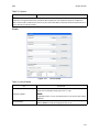
Debug Header
Windmill has one debug header placed in front of the motherboard. Debug card can be
plugged in vertically and forward facing. The debug head support functions:
Support Hot-Plug
Provide RS232 serial port connector, for use of console redirection
Two 7-segment LED displays
a. CheckPoint
2-19
BIOS
CHECKPOINTS
b. Error code (POST Error/ MRC Fatal/Warning Code
One reset switch (To trigger system reset)
2-20
BMC
Chapter 3
This section provides information and key features of BMC (Baseboard Management
Controller).
BMC
SERVER MANAGEMENT SOFTWARE
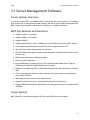
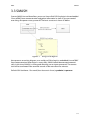
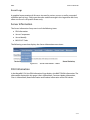
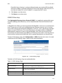
3.1 Server Management Software
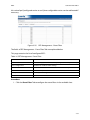
Server System Overview
In a server system, BMC is an independent system of the host server system. This independent system has its own processor and memory; the host system can be managed by the
BMC system even if the host hardware or OS hangs or is unable to function.
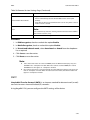
BMC Key Features and Functions
Supports IPMI v1.5 and v2.0.
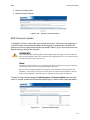
Support SNMP v1,v2c and v3.
Support SMASH.
Support delivers alerts such as SNMP traps in the Platform Event Trap (PET) format.
Out-of-band monitoring and control for sever management over LAN.
Share NIC for remote management via network.
The FRU information report includes main board part number, product name, manufacturer, etc.).
Health status/Hardware monitoring report.
Events log, view, and clear.
Event notification via lighting chassis LED indicator and Platform Event Trap (by
SNMP trap) or Mail (by Simple Mail Transfer Protocol).
Platform Event Filtering (PEF) to take selected actions for selected events, including
NMI.
Chassis management includes power control and a status report, front panel buttons and LED control.
Watchdog and auto server restart and recovery.
Supports multi-session users, and alert destination for LAN channel.
Support IPMB connecter that advanced server management card can communicate
with BMC.
Power System
BMC controls system power through GPIO pins and IPMI chassis commands.
3-1
BMC
FRONT PANEL USER INTERFACE
Front Panel User Interface
The BMC provides control panel interface functionality including indicators (Fault/status
and Identify LEDs) and buttons (Power/ID).
Power Button
The Power buttons allow to control the system status.
ID Button
The control panel Chassis Identify button toggles the state of the Chassis ID LED. If the ID
LED is off, then a button press will turn the LED on (blinking). If the LED is on, a button
press or IPMI Chassis Identify command will turn the LED off.
LEDs
The following table contains information on Status, ID and Heartbeat LED's.
Table 3.1: Status LED, ID LED, and Heartbeat LED
LEDS
COLOR
Amber (Status LED)
Status LED
Blue
ID LED
Heartbeat LED
Blue
Green
STATUS
DESCRIPTION
Blinking
System Event
Off
Normal status
On
Power on
Off
Power off
Off
Normal status
Blinking
Identify the system with interval
Solid ON
Identify the system
On/Off
BMC is not Ready
Blinking
BMC is Ready
LAN Interface
BMC LAN interface in AST2400 is assigned to its Shared NIC LAN and a dedicated NIC
(Default) in the system. IPMI Specification v2.0 defines how IPMI messages, encapsulated
in RMCP/RMCP+ packet format, can be sent to and from the BMC. This capability allows a
remote console application to access the BMC and perform the following operations:
Chassis control: obtain chassis status, reset and power-up the chassis
Obtain system sensor status
Obtain and Set system boot options
Obtain Field Replaceable Unit (FRU) information
3-2
BMC
SERIAL OVER LAN
Obtain System Event Log (SEL) entries
Obtain Sensor Data Records (SDR)
Set Platform Event Filtering (PEF)
Set LAN configurations
In addition, the BMC supports LAN alerting in the form of SNMP traps that conform to the
IPMI Platform Event Trap (PET) format.
Session and User
This BMC supports ten (10) user accounts. Each can have a different user name, password
and privilege level. Four accounts can login simultaneously. The available user privilege
levels are User, Operator, and Administrator.
Serial Over LAN
BMC supports 1 IPMI (Spec v2.0) specific SOL session. BMC supports redirect data from
UART interface.
Time Sync
In BMC design, BMC does not have a local RTC to know what time it is. Each time BMC will
get the current time from system PCH after BMC boot. The current time is updated periodically from the PCH. The remote console program interpret this time as pre-initial.
SEL
BMC supports IPMI 1.5/2.0 standard SEL operation. It can keep SEL log. Event happened in
BIOS side will be logged by using Add SEL Entry command. BMC will store them in FLASH,
the time stamp field will be filled by BMC. When SEL is full, the new SEL won’t be logged
but will go through PEF as usual. If AC powers off, all SELs will remain in NV.
Platform Event
Platform Event Filter
The BMC implements selectable action on an event or LAN alerting base on event. By
default, no any PEF entries or actions exist, applications need to configure it to enable.
Dedicated and Shared NIC
The policy to match an event to Platform Event Filter Table entry is IPMI 1.5 standard.
The action support Power off, Power Reset, Power Cycle and NMI.
3-3
BMC
BMC FIRMWARE UPDATE
All Platform Event Filter Table is default disabled.
PEF Startup Delay and Last Processed Event tracking is not supported.
PEF table lookup isn’t correlated to log SEL to SEL Repository.
Serial Alerting is no support.
BMC Firmware Update
The BMC will allow users to upgrade firmware image on following entities:
BMC
All other upgradable entities
The update capability is provided by local and remote interfaces.
DOS Recovery Utility
SOCFLASH Utility.
WebUI Update
Remote update can be performed through the remote Web console.
3-4
BMC
BMC RECOVERY
3.2 BMC Recovery
This section provides guidelines on BMC recovery process in DOS and Linux systems.
Recovery Process in DOS System
To recover BMC on a DOS system, do as follows:
1. Copy BMC firmware package to your USB key.
2. Boot into DOS.
3. Run dos.bat.
The BMC recovery is complete.
Recovery Process in Linux System
To recover BMC on a Linux system, do as follows:
1. Copy BMC firmware package to your USB drive.
2. Boot into Linux.
3. Run linux.sh.
The BMC recovery is complete.
Recovery Process in Windows System
To recover BMC on a Windows system, do as follows:
1. Copy BMC firmware package to your USB key.
2. Boot into Windows.
3. Run win.bat.
The BMC recovery is complete.
3-5
BMC
SMASH
3.3 SMASH
Quanta SMASH is a tool that allows you to use Secure Shell (SSH) to login in the embedded
Linux of BMC from remote terminal and gather information as well as give you control
over things like power resets, power off. The basic structure is shown as below:
Figure 3-1. Using SSH to login in
Here presents an activity diagram, user could use SSH to login in embedded Linux of BMC
from remote terminal. After login in successfully, SMASH would be executed automatically. In this time, SMASH is running and allowing user to input commands. The connection will be terminated if the terminal console is idle more than five minutes.
Default SSH UserName / Password (User Account in Linux): sysadmin / superuser
3-6
BMC
SMASH
Input command in Linux: ssh sysadmin@<Server IP>
Figure 3-2. SMASH Activity Diagram
Here provides you the commands about system level and BMC level.
System Level Commands
The system level commands provide you the information and power state control.
Table 3.2: Targets and Verbs
SUPPORTED VERBS
RELATED TARGETS
CD
EXIT
HELP CREATE DELETE SET SHOW RESET START STOP VERSION
/
v
v
v
v
/SYS
v
v
v
v
/SYS/voltage
v
v
v
v
v
/SYS/fan
v
v
v
v
v
/SYS/temperature
v
v
v
v
v
/SYS/powerSupply
v
v
v
v
v
v
v
v
v
v
Displays information for the board
show /SYS
3-7
BMC
SMASH
Power-on system
start /SYS
Power-off system
stop /SYS
Power-reset system
reset /SYS
Display all system voltage
show /SYS/voltage
Display all system fan
show /SYS/fan
Display all system temperature
show /SYS/temperature
Display all system power supply
show /SYS/powerSupply
/SYS
This command provides you the hig-level status of the system chassis and main power
subsystem.
Table 3.3: /SYS
PROPERTY NAME
VALID VALUE
ACCESS
DESCRIPTION
SystemMAC0
R
Display system MAC0 address
SystemMAC1
R
Display system MAC1 address
R
PowerIsOFF
indicates the system power is off
PowerIsON
indicates the system power is on.
ChassisStatus
powerIsOFF
powerIsON
Q&A
Q: I tried to turn system power off by IPMI command “power off” when there is no
response from operating system and system could not be shutdown. What is the Chassis
Status?
A: The status of ChassisStatus is “powerIsON.”
3-8
BMC
SMASH
/SYS/voltage
This command returns a high level version of the system voltages health status.
Table 3.4: /SYS/voltage
PROPERTY NAME
Sensor name list of
vlotage
VALID VALUE
na
ok
nonCritical
critical
ACCESS
DESCRIPTION
R
na
indicates the status not available /unknown
(typically because system power is off)
ok
indicates the monitored parameters within normal operating ranges
nonCritical
indicates the hardware outside normal operating range
critical
indicates the hardware exceeding specified ratings
*The sensor name list depends on the Server Hardware.
/SYS/fan
This command returns a high level version of the system fan health status.
Table 3.5: /SYS/fan
PROPERTY NAME
Sensor name list of
fan
VALID VALUE
na
ok
nonCritical
critical
ACCESS
DESCRIPTION
R
na
indicates the status not available /unknown
(typically because system power is off)
ok
indicates the monitored parameters within normal operating ranges
nonCritical
indicates the hardware outside normal operating range
critical
indicates the hardware exceeding specified ratings
*The sensor name list depends on the Server Hardware.
/SYS/temperature
This command returns a high level version of the system temperature health status.
3-9
BMC
SMASH
Table 3.6: /SYS/temperature
PROPERTY NAME
Sensor name list of
temperature
VALID VALUE
na
ok
nonCritical
critical
ACCESS
DESCRIPTION
R
na
indicates the status not available /unknown
(typically because system power is off)
ok
indicates the monitored parameters within normal operating ranges
nonCritical
indicates the hardware outside normal operating range
critical
indicates the hardware exceeding specified ratings
*The sensor name list depends on the Server Hardware.
/SYS/powerSupply
This command provides the specification of the Sensor Type sensor-specific event.
Table 3.7: /SYS/powerSupply
PROPERTY NAME
Sensor name list of
power supply
VALID VALUE
Presence*
FailDetected*
PredictiveFail*
InputLost(AC/
DC)*
AllDeasserted
ACCESS
DESCRIPTION
R
Presence
indicates the Power Supply Presence detected
FailDetected
indicates the Powser Supply Failure detected
PredictiveFail
indicates the Power Supply Predictive Failure,
the status supported or not depends on project
InputLost(AC/DC)
indicates the Power Supply input lost, such as
power cord not inserted
AllDeasserted
indicates the power supply is not inserted
R
The property is provided depend on project.
FullyRedundant
Indicates the power redundancy is OK.
RedundancyLost
Indicates the power redundancy is fail. One PSU
is removed or AC lost.
(*Note: Only for
certain models.)
Redundancy
FullyRedundant
RedundancyLost
*The sensor name list depends on the Server Hardware.
Q&A:
Q1: My system supports two power supply slots and only one power supply unit connected. What is the other power supply status?
3-10
BMC
SMASH
A1: The other power supply status is " AllDeasserted ".
Q2: My system supports two power supply slots and two power supply units connected.
But only one power cord plugged. What is the other power supply status?
A2: The other power supply status shows "Presence, PredictiveFail, InputLost(AC/DC) ".
BMC Information
The BMC level commands provide several options to configure and display parameters of
the management agent.
Table 3.8: Targets and Verbs
SUPPORTED VERBS
RELATED TARGETS
CD
EXIT
HELP CREATE DELETE SET SHOW RESET START STOP VERSION
/
v
v
v
/SP
v
v
v
v
v
v
v
v
v
Displays information for the board
show /SP
Reset BMC
reset /SP
Set server identify LED to be off
set /SP ServerIdentify=off
Set server identify LED to be on
set /SP ServerIdentify=on
Set server identify LED to be blinking
set /SP ServerIdentify=blinking
/SP
Table 3.9: /SYS/fan
PROPERTY NAME
VALID VALUE
ACCESS
DESCRIPTION
BMCVersion
R
Display BMC firmware revision
BMCGUID
R
Display BMC GUID
3-11
BMC
SMASH
Table 3.9: /SYS/fan (Continued)
PROPERTY NAME
ServerIdentify
BMCMAC
VALID VALUE
off
on
blinking
ACCESS
R/W
R
DESCRIPTION
Configuring server identify LED
Display the NIC physical address used by server
management agent
3-12
BMC
WEB GRAPHICAL USER INTERFACE (GUI) FOR ESMS
3.4 Web Graphical User Interface (GUI) for
ESMS
Using the Web GUI
The BMC firmware features an embedded web server enabling users to connect to the
BMC using a Web browser (e.g. Microsoft Internet Explorer). The Web GUI shows system
information, system events, system status of managed servers, and other system-related
information.
The Web-based GUI is supported on the following browsers:
Internet Explorer 7 and above
Firefox 8.0 and above
Google Chrome 2.0 and above
Login
Enter the IP address or URL (default DHCP\static IP address) into the address bar of the
web browser.
When connecting to the BMC the Login screen prompts for the username and password.
This authentication with SSL protection prevents unauthorized intruders from gaining
access to the BMC web server.
When a user is authenticated they can manage the server according to the privilege of
their role.
The OEM Proprietary, Administrator and Operator privilege levels are authorized to login
to the web interface. The User and No Access privilege levels do not allow access through
the BMC web GUI.
Figure 3-3.
Login Web Page
3-13
BMC
DASHBOARD
Table 4: Default Username and Password
FIELD
DEFAULT
Username
admin
Password
admin
After passing authentication, the following web page appears.
Note:
The default username and password are in lowercase characters. It is advised to change the
admin password once you have logged in.
Click the Help button on the right corner of the page for assistance, the Refresh button to
refresh the page, or the Logout button to exit.
Figure 3-4.
Main Web Page
Table 5: Main Web Page
MENU ITEM
DESCRIPTION
Dashboard
Displays the device, network, sensor monitoring and event logs information.
Server information
Shows system information.
Server Health
Monitoring status of the server.
Configuration
Configuration of the IPMI settings.
Remote Control
Launch KVM console and perform power control.
Maintenance
Allows the user to do firmware update.
Dashboard
In MegaRAC GUI, the Dashboard page displays the overall information on status of the
device.
3-14
BMC
DASHBOARD
To open the Dashboard page, click Dashboard from the main menu. A sample screenshot
of the Dashboard page is as follows:
Figure 3-5. Dashboard
A brief description of the Dashboard page is given in the next section.
Device Information
The Device Information displays the following information:
Table 6: Device Information Page
ITEM
DESCRIPTION
Firmware Revision
The revision number of the firmware.
Firmware Build Time
Firmware date and time.
BIOS Version
The current BIOS firmware version.
PSU0 MFR Revision
Display PSU0 manufacture revision.
PSU0 Firmware version
Display PSU0 Firmware version.
PSU1 MFR Revision
Display PSU1 manufacture revision.
PSU1 Firmware version
Display PSU1 firmware version.
PDB Firmware Version
The current PDB (Power Distribution Board) firmware version.
FCB Version
The current FCB (Fan Control Board) firmware version.
Top PSU Max output Power
Display Top power supply max output power (Watts).
Bottom PSU Max output Power
Display Bottom power supply max output power (Watts).
MB Position
Display the current position of the mainboard within the chassis.
Blackplane F/W version
Display backplane firmware version.
BMC NIC
Display current used NIC.
System MAC
The maximum MAC address of system LAN port is 8. From Grantley platform, BMC supports to show LAN Card Type (LOM/OCP Mezzanine/
Quanta Mezzanine) for System MAC.
BMC Date & Time
The current time of BMC system.
BMC Chipset
This field shows BMC chipset type.
3-15
BMC
DASHBOARD
Note:
BMC Chipset type support list:
(1) AST2300/AST2400: support virtual KVM function and related setting item.
(2) AST2300/AST2400 without RKVM: not support virtual KVM function and
related setting item.
(3) AST2050/AST2150: support virtual KVM function and related setting item.
If BMC Chipset type is "AST2300/AST2400 without RKVM", will remove Console
Redirection, Mouse Mode, Remote Session, and Virtual Media menu item.
Network Information
The Network Information of the device with the following fields is shown in the following
table. To edit the network Information, click Edit.
Table 7: Network Information
ITEM
DESCRIPTION
Host Name
Read only field showing the DNS Hostname of the device.
MAC Address
Read only field showing the IP address of the device.
V4 Network Mode
The v4 network mode options are the following disable, static, or DHCP.
IPv4 Address
The IPv4 address of the device (could be static or DHCP).
V6 Network Mode
The v6 network mode options are disable, static, or DHCP.
IPv6 Address:
The IPv6 address of the device.
IPv6 Link Local Address
The IPv6 link local address of the device.
Sensor Monitoring
Lists all the available sensors on the device.
The status column displays the state of the device as follows:
Table 3-1:
STATUS (ICON)
DESCRIPTION
Normal state
Warning state
Critical state
If you click on
, the sensor page for that particular sensor will be displayed.
3-16
BMC
SERVER INFORMATION
Event Logs
A graphical representation of all events incurred by various sensors as well as occupied/
available space in logs. Clicking on the color-coded rectangle in the Legend for the chart,
allows to view a list of specific events only.
Server Information
The Server Information Group consists of the following items:
FRU Information
Server Component
Server Identify
BIOS POST Code
The following screenshot displays the Server Information menu items:
Figure 3-6.
Server Information – Menu
FRU Information
In the MegaRAC GUI, the FRU Information Page displays the BMC FRU file information. The
information displayed in this page is Basic Information, Common Header Information,
Chassis Information, Board Information and Product Information of the FRU device.
3-17
BMC
FRU INFORMATION
To open the FRU Information Page, click on FRU Information on top menu. Select a FRU
Device ID from the Basic Information section to view the details of the selected device. A
screenshot of FRU Information page is shown as follows:
Figure 3-7. FRU Information Page
A brief description of the fields is given in the following sections.
Basic Information
Table 4: Basic Information
ITEM
DESCRIPTION
FRU device ID
The ID of the device.
FRU Device Name
The device name of the selected FRU device.
Chassis Information
Chassis Information Area Format Version
Chassis Type
Chassis Part Number
Chassis Serial Number
Chassis Extra
Board Information
Board Information Area Format Version
Language
Manufacture Date Time
Board Manufacturer
3-18
BMC
FRU INFORMATION
Board Product Name
Board Serial Number
Board Part Number
FRU File ID
Board Extra
Product Information
Product Information Area Format Version
Language
Manufacturer Name
Product Name
Product Part Number
Product Version
Product Serial Number
Asset Tag
Server Component
The Component Information page displays the CPU and memory information. The Number of CPU Socket field and the Number of Memory Slot field display the total number of
the motherboard supported.
Figure 3-8. Component Information Page
Table 5: Component Information Page
ITEM
CPU Information
DESCRIPTION
Displays the following information:
CPU ID,
Status,
Socket,
Manufacturer,
Model,
Frequency
3-19
BMC
FRU INFORMATION
Table 5: Component Information Page (Continued)
ITEM
Memory Information
DESCRIPTION
Displays the following information:
Memory ID,
Status,
Socket,
Module Size,
Model,
Frequency
Server identify
The Server Identify page displays the indicator LED status. You can select a Server Identify
Operation to control the indicator LED.
Figure 3-9.
Server Identify Page
Table 6: Server Identify Page
ITEM
DESCRIPTION
Current Server Identify Status
The server status: On or Off.
Server Identify Operation
Server identify LED operation with the following options:
ON
OFF
Blink
Server Identify Timeout
Server timeout value when a Blink Identify Operation is selected. For
Blink Operation the time period must be from 1 to 255 seconds. When
255 seconds is selected, the blinking is continuous.
Perform Action
Executes the selected Server Identify Operation.
3-20
BMC
FRU INFORMATION
BIOS POST Code
The page displays recent BIOS Port 80h POST code.
Figure 3-10. BIOS POST Code
Table 7: BIOS POST Code Page
ITEM
DESCRIPTION
Current Codes
Current BIOS Port 80h POST code
Previous Codes
Current BIOS Port 80h POST code
Server Health Group
The Server Health Group consists of the following items:
Sensor Readings
Event Log
3-21
BMC
FRU INFORMATION
The Server Health screenshot allows to select Sensor Readings or Event Log as shown in
the following image:
Figure 3-11. Server Health – Menu
Sensor Readings
In MegaRAC GUI, the Sensor Readings page displays all the sensor related information.
To open the Sensor readings page, click Server Health > Sensor Readings from the top
menu. Click on a record to display more information on a particular sensor, including
thresholds and a graphical representation of all associated events. A screenshot of Sensor
Readings page is shown in the following image:
Figure 3-12. Sensor Readings Page
A brief description of the Sensor Readings page fields is given in the following sections.
Sensor Type
This drop down menu allows you to select the type of sensor. The List of sensors with the
Sensor Name, Status and Current Reading will be displayed in the list. If you select All Sensors, all the available sensor details will appear else you can choose the sensor type that
3-22
BMC
FRU INFORMATION
you want to display in the list. Some examples of other sensors include Temperature Sensors, Fan Sensors, and Voltage Sensors etc.
Select a particular sensor from the list. On the right hand side of the screen you can view
the Thresholds for this sensor.
Thresholds are of six types:
Lower Non-Recoverable (LNR)
Lower Critical (LC)
Lower Non-Critical (LNC)
Upper Non-Recoverable (UNR)
Upper Critical (UC)
Upper Non-Critical (UNC)
The threshold states could be:
Lower Non-critical - going low,
Lower Non-critical - going high,
Lower Critical - going low,
Lower Critical - going high,
Lower Non-recoverable - going low,
Lower Non-recoverable - going high,
Upper Non-critical - going low,
Upper Non-critical - going high,
Upper Critical - going low,
Upper Critical - going high,
Upper Non-recoverable - going low,
Upper Non-recoverable - going high.
A graphical view of these events (Number of event logs vs. Thresholds) can be viewed as
shown in the Sensor Readings Page screenshot.
3-23
BMC
FRU INFORMATION
Live Widget
The widget window can be turned On and Off for a selected sensor. Widget provides a
dynamic representation of the readings for the sensor. The following image shows and
example widget:
Figure 3-13. Widget Window
Note:
Widgets are little gadgets, which provide real time information about a particular sensor. User
can track a sensor's behavior over a specific amount of time at specific intervals. The result will
be displayed as a line graph in the widget. The session will not expire, until the widgets gets a
live data of the last widget that is kept opened.
View this Event Log
View the Event Log page for the selected sensor.
Sensor Reading status
You can read currently sensor status in this page, each sensor name have its SDR setting
data, the status according SDR setting will display as following matrix:
Table 8: Sensor Readings status
STATUS
CURRENT READING
N/A
N/A
All deasserted
0x80xx(*2)
Normal
Value with unit
Event string(*1)
(*1) Please refer IPMI2.0 standard specification chapter 42.
(*2) Please refer IPMI2.0 standard specification chapter 42 and SDR setting in BMC function specification.
Event Log
In MegaRAC GUI, this page displays the list of event logs occurred by the different sensors
on this device. Double click on a record to see the details of that entry. You can use the
3-24
BMC
FRU INFORMATION
sensor type or sensor name filter options to view those specific events or you can also sort
the list of entries by clicking on any of the column headers.
To open the Event Log page, click Server Health > Event Log from the top menu. A sample screenshot of the Event Log page is shown as follows.
Figure 3-14.
Event Log Page
The Event Log page consists of the following fields.
Table 9: Event Log Page
ITEM
DESCRIPTION
Event Log Category
The category options:
All Events,
System Event Records,
BIOS Generated Events,
SMI Handler Events,
System Management Software Events,
System Software - OEM Events,
Remote Console software Events,
Terminal Mode Remote Console software Events.
Filter Type
Filtering can be done with the sensors mentioned in the list.
Once the Event Log category and Filter type are selected, the list of
events will be displayed with:
Event ID
Time Stamp
Sensor Type
Sensor Name
Description
BMC Timezone
BMC UTC offset timestamp value of the events.
Client Timezone
Events of client UTC offset timestamp.
Clear All Event Logs
Deletes all the existing records for all the sensors.
Download All Event Logs
(Text format):
To download all existing records for all sensors.
Default filename is SEL.txt.
Download All Event Logs
(Hex format)
To download all existing records for all sensors.
Default filename is SEL_Hex.txt.
Procedure:
3-25
BMC
CONFIGURATION GROUP
1. Select the event categories from the Event Log Category drop-down menu.
2. Select the sensor name filter to view the event for the selected filter from the Filter
Type drop-down list.
3. Select either BMC Timezone or Client Timezone. The list of events is listed.
4. Click the Clear All Event Logs button to clear all events from the list.
SEL Severity
The Event Log page specifies the severity of the SEL to identify the event severity code as
follows:
: Severity Information
: Severity Warning
: Severity Critical
: Severity Non-Recoverable
: Severity Unspecified
Configuration Group
Configuration Group page allows access to various configuration settings. A screenshot of
the Configuration Group menu is shown in the following figure:
Figure 3-15.
Configuration Group Menu
A detailed description of the Configuration menu is given in the following sections.
3-26
BMC
CONFIGURATION GROUP
Active Directory
An active directory is a directory structure used on Microsoft Windows-based computers
and servers to store information and data about networks and domains. An active directory (sometimes referred to as an AD) does a variety of functions including the ability to
provide information on objects, helps organize these objects for easy retrieval and access,
allows access by end users and administrators and allows the administrator to set security
up for the directory.
This page in MegaRAC SP-X, allows you to Configure Active Directory Server Settings.
To open Active Directory Settings page, click Configuration > Active Directory from the
main menu. A sample screenshot of Active Directory Settings Page is shown in the screenshot below.
Figure 3-16. Active Directory Settings Page
Table 10: Active Directory Settings Page
ITEM
DESCRIPTION
Advanced Settings
This option is used to configure Active Directory Advanced Settings.
Options are Enable Active Directory Authentication, User Domain name,
Time Out and up to three Domain Controller Server Addresses.
Role Group ID
The name that identifies the role group in the Active Directory.
This name identifies the role group in Active Directory.
Group Name
Note:
Role Group Name is a string of 64 alpha-numeric characters.
Special symbols (hyphen and underscore) are allowed.
The domain where the role group is located.
Group Domain
Note:
Domain Name is a string of 255 alpha-numeric characters.
Special symbols (hyphen and underscore) and dot are allowed.
Group Privilege
The level of privilege to assign to this role group.
Add Role Group
To add a new role group to the device.
Modify Role Group
To modify that role group. Alternatively, double click on the configured
slot.
Delete Role Group
To delete an existing Role Group.
Procedure:
3-27
BMC
CONFIGURATION GROUP
Entering the details in Advanced Active Directory Settings Page
1. Click on Advanced Settings to open the Advanced Active Directory Settings Page.
Figure 3-17. Active Directory Settings Page
2. In the Active Directory Settings Page, enter the following details.
3. Active Directory Authentication: To enable/disable Active Directory, check or
uncheck the Enable checkbox respectively.
Note:
If you have enabled Active Directory Authentication, enter the required information to access
the Active Directory server.
4. Specify the Domain Name for the user in the User Domain Name field. e.g. MyDomain.com.
5. Specify the time (in seconds) to wait for Active Directory queries to complete in the
Time Out field.
Note:
Default Time out value: 120 seconds.
Range from 15 to 300 allowed.
6. Configure IP addresses in Domain Controller Server Address1, Domain Controller Server Address2 & Domain Controller Server Address3.
Note:
IP address of Active Directory server: At least one Domain Controller Server Address must be
configured.
IP Address made of 4 numbers separated by dots as in "xxx.xxx.xxx.xxx".
Each number ranges from 0 to 255.
First number must not be 0.
Domain Controller Server Addresses will supports IPv4 Address format and IPv6 Address format.
7. Click Save to save the entered settings and return to Active Directory Settings Page.
8. Click Cancel to cancel the entry and return to Active Directory Settings Page.
To add a Role Group
3-28
BMC
CONFIGURATION GROUP
9. In the Active Directory Settings Page, select a blank row and click Add Role Group
to open the Add Role group Page as shown in the screenshot below.
Figure 3-18.
Add Role group Page
10. In the Role Group Name field, enter the name that identifies the role group in the
Active Directory.
Note:
Role Group Name is a string of 64 alpha-numeric characters.
Special symbols hyphen and underscore are allowed.
11. In the Role Group Domain field, enter the domain where the role group is located.
Note:
Domain Name is a string of 255 alpha-numeric characters.
Special symbols hyphen, underscore and dot are allowed.
12. In the Role Group Privilege field, enter the level of privilege to assign to this role
group.
13. Click Add to save the new role group and return to the Role Group List.
14. Click Cancel to cancel the settings and return to the Role Group List.
To modify a Role Group
15. In the Advanced Directory Settings Page, select the row that you wish to modify and
click Modify Role Group.
16. 16. Make the necessary changes and click Save.
To delete a Role Group
17. In the Advanced Directory Settings Page, select the row that you wish to delete and
click Delete Role Group.
DNS
The Domain Name System (DNS) is a distributed hierarchical naming system for computers, services, or any resource connected to the Internet or a private network. It associates
the information with domain names assigned to each of the participants. Most importantly, it translates domain names meaningful to humans into the numerical (binary) identifiers associated with networking equipment for the purpose of locating and addressing
these devices worldwide.
3-29
BMC
CONFIGURATION GROUP
In Mega-RAC GUI, the DNS Server settings page is used to manage the DNS settings of a
device.
In DNS Server Settings page, user can click Configuration > DNS from the main menu. A
sample screenshot of DNS Server Settings Page is shown in the screenshot below.
Figure 3-19. DNS Server Settings Page
The fields of DNS Server Settings page are explained below.
Table 11: DNS Server Settings Page
ITEM
DESCRIPTION
Host configuration
Host Settings
Choose either Automatic or Manual settings.
Host Name
It displays hostname of the device. If the Host setting is chosen as Manual, then specify the hostname of the device.
Register BMC
Register BMC
To enable/disable Register BMC.
Domain Name Configuration
It lists the option for domain interface as Manual, v4 or v6 for multiLAN
channels.
Domain Settings
Note:
If you choose DHCP, then select v4 or v6 for DHCP servers.
Domain Name
It displays the domain name of the device. If the Domain setting is chosen as Manual, then specify the domain name of the device. If you chose
Automatic, the Domain Name cannot be configured as it will be done
automatically. The field will be disabled.
Domain Name Server Configuration
DNS Server Settings:
It lists the option for DNS settings for the device, Manual and available
LAN interfaces. If you choose Manual setting, you have to configure the
DNS Server IP addresses. If you have chosen DHCP, then you have to
select the interface from which the IP address is to be received.
3-30
BMC
CONFIGURATION GROUP
Table 11: DNS Server Settings Page (Continued)
ITEM
DESCRIPTION
If IP Priority is IPv4, it will have 2 IPv4 DNS servers and 1 IPv6 DNS server.
If IP Priority is IPv6, it will have 2 IPv6 DNS servers and 1 IPv4 DNS server.
IP Priority
Note:
It is not applicable for Manual configuration.
DNS Server1,
DNS Server2, and
DNS Server3
Specify the DNS (Domain Name System) server address to be configured for the BMC.
IPv4 Address made of 4 numbers separated by dots as in
"xxx.xxx.xxx.xxx".
Each number ranges from 0 to 255.
First number must not be 0.
DNS Server Address will support the following:
IPv4 Address format.
IPv6 Address format.
Note:
If IP Priority is IPv4 then DNS Server1, DNS Server2 will be IPv4
and DNS Server3 will be IPv6.
If IP Priority is IPv6 then DNS Server1, DNS Server2 will be IPv6
and DNS Server3 will be IPv4.
If no IP, DNS Server field will be empty.
Save
To save the entered changes.
Reset
To reset the entered changes.
Procedure:
1. Choose the Host Configuration either Automatic or Manual.
Note:
If you choose Automatic, you need not enter the Host Name and if you choose Manual, you
need to enter the Host Name.
2. Enter the Host Name in the given field if you have chosen Manual Configuration.
3. Under Register BMC,
Check the option Register BMC to register with this DNS settings.
4. In the Domain name Configuration,
Select the Domain Settings from the drop-down list.
Enter the Domain Name in the given field.
5. In the Domain Name Server Configuration,
Select the DNS Server Settings, from the drop-down list.
In the IP Priority, IPV4 or IPV6 as a top priority.
In the DNS Server1/DNS Server2/DNS Server3 field,
3-31
BMC
CONFIGURATION GROUP
If the DNS Server Settings is setting to Manual mode, user needs to fill those fields
with DNS IP address manually according to IPv4 or IPv6 format. Otherwise, if it is in
non-Manual mode, DNS server IP address is assigned by DHCP server.
6. Click Save to save the entries.
7. Click Reset to reset the entries.
LDAP/E-Directory
The Lightweight Directory Access Protocol (LDAP) is an application protocol for querying and modifying data of directory services implemented in Internet Protocol (IP) networks.
In MegaRAC GUI, LDAP is an Internet protocol that MegaRAC® card can use to authenticate
users. If you have an LDAP server configured on your network, you can use it as an easy
way to add, manage and authenticate MegaRAC® card users. This is done by passing login
requests to your LDAP Server. This means that there is no need to define an additional
authentication mechanism, when using the MegaRAC card. Since your existing LDAP
Server keeps an authentication centralized, you will always know who is accessing the network resources and can easily define the user or group-based policies to control access.
To open LDAP Settings page, click Configuration > LDAP from the main menu. A sample
screenshot of LDAP Settings Page is shown in the screenshot below.
Figure 3-20. LDAP Settings Page
The fields of LDAP Settings Page are explained below.
Table 12: LDAP Settings Page
ITEM
DESCRIPTION
Advanced Settings
To configure LDAP Advanced Settings. Options are Enable LDAP
Authentication, IP Address, Port and Search base.
Add Role Group
To add a new role group to the device. Alternatively, double click on a
free slot to add a role group.
Modify Role Group
To modify the particular role group.
Delete Role Group
To be delete a role group from the list.
3-32
BMC
CONFIGURATION GROUP
Procedure:
Entering the details in Advanced LDAP Settings Page
1. In the LDAP Settings Page, click Advanced Settings. A sample screenshot of LDAP
Settings page is given below.
Figure 3-21. Advanced LDAP Settings
2. To enable/disable LDAP Authentication, check or uncheck the Enable checkbox
respectively.
Note:
During login prompt, use username to login as an LDAP Group member.
3. Enter the IP address of LDAP server in the IP Address field.
Note:
IP Address made of 4 numbers separated by dots as in 'xxx.xxx.xxx.xxx'.
Each Number ranges from 0 to 255.
First Number must not be 0.
Supports IPv4 Address format and IPv6 Address format.
4. Specify the LDAP Port in the Port field.
Note:
Default Port is 389. For Secure connection, default port is 636.
5. Enter the Search Base. The Search base tells the LDAP server which part of the
external directory tree to search. The search base may be something equivalent to
the organization, group of external directory.
Note:
Search base is a string of 4 to 63 alpha-numeric characters.
It must start with an alphabetical character.
Special Symbols like dot (.), comma (,), hyphen(?]), underscore (_), equal-to (=) are
allowed.
Example: ou=login,dc=domain,dc=com
6. Click Save to save the settings.
7. Click Cancel to cancel the modified changes.
3-33
BMC
CONFIGURATION GROUP
To add a Role Group
8. In the LDAP Settings Page, select a blank row and click Add Role Group to open the
Add Role Group Page as shown in the screenshot below.
Figure 3-22. Add Role Group Page
9. In the Role Group Name field, enter the name that identifies the role group.
Note:
Role Group Name is a string of 64 alpha-numeric characters.
Special symbols hyphen and underscore are allowed.
10. In the Role Group Search Base field, enter the path from where the role group is
located to Base DN.
Note:
Search Base is a string of 255 alpha-numeric characters.
Special symbols hyphen, underscore and dot are allowed.
11. In the Role Group Privilege field, enter the level of privilege to assign to this role
group.
12. Click Add to save the new role group and return to the Role Group List.
13. Click Cancel to cancel the settings and return to the Role Group List.
To Modify Role Group
14. In the LDAP Settings Page, select the row that you wish to modify and click Modify
Role Group.
15. Make the necessary changes and click Save.
To Delete a Role Group
16. In the LDAP Settings Page, select the row that you wish to delete and click Delete
Role Group.
Mouse Mode
In MegaRAC GUI, Redirection Console handles mouse emulation from local window to
remote screen in either of two methods. User has to be an Administrator to configure this
option. To open Mouse Mode page, click Configuration > Mouse Mode from the main
3-34
BMC
CONFIGURATION GROUP
menu. A sample screenshot of Mouse Mode Settings Page is shown in the screenshot
below.
Figure 3-23.
Mouse Mode Settings Page
The fields of Mouse Mode Settings page are explained below.
Table 13: Mouse Mode Settings Page
ITEM
DESCRIPTION
Absolute Mode
The absolute position of the local mouse is sent to the server.
Relative Mode
Relative mode sends the calculated relative mouse position displacement to the server.
Other Mode
For the Host OS which is neither Absolute Mode nor Relative Mode.
Save
To save any changes made.
Reset
To Reset the modified changes.
Procedure:
1. Choose either of the following as your requirement:
Set mode to Absolute
Note:
Applicable for all Windows versions; RHEL Linux versions not below than RHEL6; Fedora Linux
versions not below than FC14.
Set mode to Relative
Note:
Applicable for RHEL Linux versions below than RHEL6; Fedora Linux versions below than FC14;
SLES Linux versions below than SLES11.
Set mode to Other
Note:
Applicable for SLES Linux version SLES11.
2. Click Save button to save the changes made.
3. Click Reset to reset the modified changes.
3-35
BMC
CONFIGURATION GROUP
Network
In MegaRAC GUI, the Network Settings Page is used to configure the network settings for
the available LAN channels.
To open Network Settings page, click Configuration > Network from the main menu. A
sample screenshot of Network Settings Page is shown in the screenshot below.
Figure 3-24. Network Settings Page
The fields of Network Settings page are explained below.
3-36
BMC
CONFIGURATION GROUP
Table 14: Network Settings Page
ITEM
DESCRIPTION
LAN Interface
Lists the LAN interfaces.
LAN Settings
To enable or disable the LAN Settings.
MAC Address
This field displays the MAC Address of the device. This is a read only
field.
IPv4 Settings
This option lists the IPv4 configuration settings.
Obtain IP Address automatically: This option is to dynamically configure IPv4 address using DHCP (Dynamic Host Configuration Protocol).
IPv4 Address, Subnet Mask, and Default Gateway: These fields are for
specifying the static IPv4 address, Subnet Mask and Default Gateway
to be configured to the device.
Note:
IP Address made of 4 numbers separated by dots as in
"xxx.xxx.xxx.xxx".
Each Number ranges from 0 to 255.
First Number must not be 0.
IPv6 Configuration
This option lists the following IPv6 configuration settings.
IPv6 Settings: This option is to enable the IPv6 settings in the device.
Obtain an IPv6 address automatically: This option is to dynamically
configure IPv6 address using DHCP (Dynamic Host Configuration
Protocol).
IPv6 Address: To specify a static IPv6 address to be configured to the
device. Eg: 2004:2010
Subnet prefix length: To specify the subnet prefix length for the IPv6
settings.
Note:
Value ranges from 0 to 128.
Default Gateway: Specify v6 default gateway for the IPv6 settings.
Reserved IPv6 Address: Some IPv6 addresses are reserved by
IETF. List is showed as below, so when users set these Blocking
IPv6 addresses, WebUI will pop-up warning message.
VLAN Configuration
It lists the VLAN configuration settings.
VLAN Settings: To enable/disable the VLAN support for selected
interface.
VLAN ID: The Identification for VLAN configuration.
Value ranges from 1 to 4095.
VLAN Priority: The priority for VLAN configuration.
Value ranges from 1 to 7.
7 is the highest priority for VLAN.
Save
To save the entries.
Reset
To Reset the modified changes.
3-37
BMC
CONFIGURATION GROUP
Table 15: Reserved IPv6 Address
IPV6 PREFIX
ALLOCATION
REFERENCE
IPV6 PREFIX
ALLOCATION
REFERENCE
0000::/8
Reserved by IETF
[RFC4291]
c000::/3
Reserved by IETF
[RFC4291]
0100::/8
Reserved by IETF
[RFC4291]
e000::/4
Reserved by IETF
[RFC4291]
0200::/7
Reserved by IETF
[RFC4048]
f000::/5
Reserved by IETF
[RFC4291]
0400::/6
Reserved by IETF
[RFC4291]
f800::/6
Reserved by IETF
[RFC4291]
0800::/5
Reserved by IETF
[RFC4291]
fe00::/9
Reserved by IETF
[RFC4291]
1000::/4
Reserved by IETF
[RFC4291]
fe80::/10
Reserved by IETF
[RFC4291]
1000::/4
Reserved by IETF
[RFC4291]
fec0::/10
Reserved by IETF
[RFC3879]
6000::/3
Reserved by IETF
[RFC4291]
ff00::/8
Reserved by IETF
[RFC4291]
8000::/3
Reserved by IETF
[RFC4291]
2001::/32
Reserved by IETF
[RFC4380]
a000::/3
Reserved by IETF
[RFC4291]
PEF
Platform Event Filtering (PEF) provides a mechanism for configuring the BMC to take
selected actions on event messages that it receives or has internally generated. These
actions include operations such as system power?]off, system reset, as well as triggering
the generation of an alert.
In MegaRAC GUI, the PEF Management is used to configure the following:
Event Filter
Alert Policy
LAN Destination
To open PEF Management Settings page, click Configurations > PEF from the main
menu. A sample screenshot of PEF Management Settings Page is shown in the screen shot
below. Each tab is explained below.
Event Filter Tab
A PEF implementation is recommended to provide at least 16 entries in the event filter
table. A subset of these entries should be pre?]configured for common system failure
events, such as over?]temperature, power system failure, fan failure events, etc. Remaining
entries can be made available for ?eOEM?f or System Management Software configured
events. Note that individual entries can be tagged as being reserved for system use ?] so
3-38
BMC
CONFIGURATION GROUP
this ratio of pre?]configured entries to run?]time configurable entries can be reallocated if
necessary.
Figure 3-25. PEF Management – Event Filter
The fields of PEF Management – Event Filter Tab are explained below.
This page contains the list of configured PEF’s.
Table 16: PET Management - Event Filter
ITEM
DESCRIPTION
PEF ID
This field displays the ID for the newly configured PEF entry (read-only).
Filter configuration
Check box to enable the PEF settings.
Event Filter Action
Check box to enable PEF Alert action. This is a mandatory field.
Sensor Name
To choose the particular sensor from the sensor list.
Modify
To modify the existing entries.
Delete
To delete Event filter list.
Procedure:
1. Click the Event Filter Tab to configure the event filters in the available slots.
3-39
BMC
CONFIGURATION GROUP
2. Select one of PEF ID list and click Modify to modify event Filter entry page. A sample
screenshot of modify Event Filter Page is in seen the screenshot below.
Figure 3-26. Add Event Filter Entry Page
3. In the Event Filter Configuration section,
PEF ID displays the ID for configured PEF entry (read?]only).
In filter configuration, check the box to enable the PEF settings.
4. In the Filter Action configuration section,
Event Filter Action is a mandatory field and checked by default, which enable PEF
Alert action (read-only).
Select any one of the Power action either Power down, Power reset or Power cycle
from the drop down list
Choose any one of the configured alert policy number from the drop down list.
Note:
Alert Policy has to be configured - under Configuration -> PEF -> Alert Policy.
5. In the Sensor configuration section,
Select the s type of sensor that will trigger the event filter action.
In the sensor name field, choose the particular sensor from the sensor list.
Choose event option to be either All Events or Sensor Specific Events.
6. Click Modify to accept the modification and return to Event filter list.
7. Click Reset to reset the modification done.
8. Click on Cancel to cancel the modification and return to Event filter list.
9. In the Event filter list, to modify a configuration, select the slot to be modified and
click Modify.
10. In the Event filter list, click Delete to delete the existing filter.
3-40
BMC
CONFIGURATION GROUP
Alert Policy Tab
This page is used to configure the Alert Policy and LAN destination. You can add, delete or
modify an entry in this page.
Figure 3-27. PEF Management – Alert Policy
The fields of the PEF Management – Alert Policy Tab are explained below.
Table 17: PEF Management - Alert Policy
ITEM
DESCRIPTION
Policy Entry #
Displays Policy entry number for the newly configured entry (readonly).
Policy Number
Displays the Policy number of the configuration.
Policy Configuration
To enable or disable the policy settings.
Policy Set
To choose any one of the Policy set values from the list.
0: Always send alert to this destination.
1: If alert to previous destination was successful, do not send alert to
this destination. Proceed to next entry in this policy set.
2: If alert to previous destination was successful, do not send alert to
this destination. Do not process any more entries in this policy set.
3: If alert to previous destination was successful, do not send alert to
this destination. Proceed to next entry in this policy set that is to a
different channel.
4: If alert to previous destination was successful, do not send alert to
this destination. Proceed to next entry in this policy set that is to a
different destination type.
Channel Number
To choose a particular channel from the available channel list.
3-41
BMC
CONFIGURATION GROUP
Table 17: PEF Management - Alert Policy (Continued)
ITEM
DESCRIPTION
To choose a particular destination from the configured destination list.
Destination Selector
Note:
LAN Destination has to be configured - under Configuration -> PEF ->
LAN Destination.
Modify
To modify the existing entries.
Delete
To delete Alert Policy list.
Procedure:
1. In the Alert Policy Tab, select the slot for which you have to configure the Alert policy. That is, In the Event Filter Entry Page, if you have chosen Alert Policy number
as 4, you have to configure the 4th slot (the slot with Policy Number 4) in the Alert
Policy Tab.
2. Double click the slot and click Modify to open the Add Alert Policy Entry Page as
shown in the screenshot below.
Figure 3-28. Add Alert Policy Entry Page
3. Policy Entry # is a read only field.
4. Select the Policy Number from the list.
5. In the Policy Configuration field, check Enable if you wish to enable the policy settings.
6. In the Policy Set field, choose any of the Policy set from the list.
7. In the Channel Number field, choose particular channel from the available channel
list.
8. In the Destination Selector field, choose particular destination from the configured destination list.
Note:
LAN Destination has to be configured under Configuration -> PEF -> LAN Destination. That
is if you select the number 4 for destination selector in Alert Policy Entry page, then you have
to configure the 4th slot (LAN Destination Number 4) in the LAN Destination tab.
9. In the Alert String field, enable the check box if the Alert policy entry is Event Specific.
3-42
BMC
CONFIGURATION GROUP
10. In the Alert String Key field, choose any one value that is used to look up the Alert
String to send for this Alert Policy entry.
11. Click Add to save the new alert policy and return to Alert Policy list.
12. Click Cancel to cancel the modification and return to Alert Policy list.
13. In the Alert Policy Page, to modify a configuration, select the slot to be modified
and click Modify.
14. In the Alert Policy Page, to delete a configuration, select the slot and click Delete.
PEF Management LAN Destination Page
This page is used to configure the Event filter, Alert Policy and LAN destination. A sample
screenshot of PEF Management LAN Destination Page is given below.
Figure 3-29. PEF Management - LAN Destination
The fields of PEF Management – LAN Destination Tab are explained below.
Table 18: PEF Management - LAN Destination
ITEM
DESCRIPTION
LAN Destination
Displays Destination number for the newly configured entry (readonly).
Destination Type
Destination type can be either an SNMP Trap or an Email alert.
For Email alerts, the 3 fields – Username, Subject and body of the message needs to be filled. The SMTP server information also has to be
added - under Configuration -> SMTP.
For SNMP Trap, only the destination IP address has to be filled.
3-43
BMC
CONFIGURATION GROUP
Table 18: PEF Management - LAN Destination (Continued)
ITEM
DESCRIPTION
Destination Address
If Destination type is SNMP Trap, then enter the IP address of the system
that will receive the alert. Destination address will support the following:
IPv4 address format.
IPv6 address format.
Send Test Alert
These fields must be configured if email alert or SNMP Trap is chosen as
destination type. This field will send a test message in the message
field's content to specified destination.
Modify
To modify existing LAN destination list.
Delete
To delete LAN destination list.
Procedure:
1. In the LAN Destination Tab, choose the slot to be configured. This should be the
same slot that you have selected in the Alert Policy Entry?] Destination Selector
field. That is if you have chosen the Destination Selector as 4 in the Alert Policy Entry
page of Alert Policy Tab, then you have to configure the 4th slot of LAN Destination
Page.
2. Double click the slot and click Modify. This opens the Add LAN Destination entry.
Figure 3-30. Add LAN Destination entry Page
3. In the LAN Destination field, the destination for the newly configured entry is displayed and this is a read only field.
4. In the Destination Type field, select the one of the types.
5. In the Destination Address field, enter the destination address.
6. Select the User Name from the list of users.
7. In the Subject field, enter the subject.
8. In the Message field, enter the message.
9. Click Add to save the new LAN destination and return to LAN destination list.
10. Click Cancel to cancel the modification and return to LAN destination list.
11. In the LAN Destination Tab, to modify a configuration, select the row to be modified and click Modify.
12. In the LAN Destination Tab, to delete a configuration, select the slot and click
Delete.
3-44
BMC
CONFIGURATION GROUP
Configuring the SNMP:
1. Navigate to PEF Management.
2. Select LAN Destination tab in Configuration section.
3. Select from LAN Destination menu SNMP Trap.
1
2
2
3
Figure 3-31. Selecting SNMP Trap
A Modify LAN Destination entry menu opens.
4. Key in an IP address to the Destination Address field.
5. To complete the SNMP configuration procedure, click Modify.
4
5
Figure 3-32. Inserting the IP Address
3-45
BMC
CONFIGURATION GROUP
RADIUS
RADIUS is a modular, high performance and feature-rich RADIUS suite including server, clients, development libraries and numerous additional RADIUS related utilities.
In MegaRAC GUI, this page is used to set the RADIUS Authentication.
To open RADIUS Settings page, click Configuration > RADIUS from the main menu. A sample screenshot of RADIUS Settings Page is shown in the screenshot below.
Figure 3-33.
RADIUS Settings Page
The fields of RADIUS Settings Page are explained below.
Table 19: RADIUS Settings Page
ITEM
RADIUS Authentication
DESCRIPTION
Option to enable RADIUS authentication.
The RADIUS Port number.
Port
Note:
Default Port is 1812.
The Time out value in seconds.
Time Out
Note:
Default Timeout value is 3seconds.
Timeout value ranges from 3 to 300.
The IP address of RADIUS server.
Note:
Server Address
IP Address made of 4 numbers separated by dots as in
"xxx.xxx.xxx.xxx".
Each Number ranges from 0 to 255.
First Number must not be 0.
The Authentication Secret for RADIUS server.
Note:
Secret
This field will not allow more than 31 characters.
Secret phrase must be at least 4 characters long.
No more than 64 characters are allowed.
3-46
BMC
CONFIGURATION GROUP
Table 19: RADIUS Settings Page (Continued)
ITEM
DESCRIPTION
Save
To save the settings.
Reset
To reset the modified changes.
Procedure:
1. Enable the RADIUS Authentication checkbox to authenticate the RADIUS.
2. Enter the port number in the Port Number field.
3. Enter the time out value in seconds in the Time out field.
4. Enter the address of the server in the Server Address field.
5. Enter the authentication secret for RADIUS Server in the Secret field.
6. Click Save to save the entered details.
7. Click Reset to reset the entered details.
Remote Session
In MegaRAC SP, use this page to configure virtual media configuration settings for the
next redirection session. Encryption is disabled by default.
To open Remote Session page, click Configuration > Remote Session from the main
menu. A sample screenshot of Remote Session Page is shown in the screenshot below.
Figure 3-34. Remote Session
The fields of Remote Session Settings Page are explained below.
Table 20: Remote Session Settings Page
ITEM
DESCRIPTION
KVM Encryption
Enable/Disable encryption on KVM data for the next redirection session.
Media Encryption
Enable/Disable encryption on Media data for the next redirection session.
3-47
BMC
CONFIGURATION GROUP
Table 20: Remote Session Settings Page (Continued)
ITEM
Virtual Media Attach Mode
DESCRIPTION
Two types of VM attach mode are available:
Attach: Immediately attaches Virtual Media to the server upon
bootup.
Auto Attach: Attaches Virtual Media to the server only when a virtual
media session is started.
To save the current changes.
Note:
Save
It will automatically close the existing remote redirection either KVM or
Virtual media sessions, if any.
Reset
To reset the modified changes.
Procedure:
1. In KVM encryption, check or uncheck the option Enable.
2. In Media Encryption, check or uncheck the option Enable.
3. In Virtual media Attach mode, select Auto Attach or Attach from the dropdown
list as required.
4. Click Save to save the entries.
5. Click Reset to reset the entries
‘.
Note:
If we choose more than one virtual CDROMs, then the RHEL5 host displays only one
CDROM in the “Computer” window. When we redirect second CDROM, the second
CDROM device will appear in “Computer” window.
If we choose more than 2 virtual Hard disks, then the RHEL5 host displays only two hard
disks in “Computer” window. When we redirect third hard disk, the third hard disk will
appear in “Computer” window
SMTP
Simple Mail Transfer Protocol (SMTP) is an Internet standard for electronic mail (e-mail)
transmission across Internet Protocol (IP) networks.
Using MegaRAC GUI, you can configure the SMTP settings of the device.
3-48
BMC
CONFIGURATION GROUP
To open SMTP Settings page, click Configuration > SMTP from the main menu. A sample
screenshot of SMTP Settings Page is shown in the screenshot below.
Figure 3-35. SMTP Settings Page
The fields of SMTP Settings Page are explained below.
Table 21: SMTP Settings Page
ITEM
DESCRIPTION
LAN Channel Number
Displays the list of LAN channels available.
Sender Address
The 'Sender Address' valid on the SMTP Server.
Machine Name
The 'Machine Name' of the SMTP Server.
Machine Name is a string of maximum 15 alpha-numeric characters.
Space, special characters are not allowed.
Primary SMTP Server
Lists the Primary SMTP Server configuration.
The 'IP address' of the SMTP Server. It is a mandatory field.
Note:
IP Address made of 4 numbers separated by dots as in "xxx.xxx.
xxx.xxx".
Each Number ranges from 0 to 255.
First Number must not be 0.
Supports IPv4 Address format and IPv6 Address format.
Server Address
To enable/disable SMTP Authentication.
Note:
SMTP Server Authentication Types supported are:
SMTP Server requires Authentication
CRAM-MD5
LOGIN
PLAIN
If the SMTP server does not support any one of the above authentication types, the user will get an error message stating, "Authentication
type is not supported by SMTP Server"
3-49
BMC
CONFIGURATION GROUP
Table 21: SMTP Settings Page (Continued)
ITEM
DESCRIPTION
The username to access SMTP Accounts.
Note:
Username
User Name can be of length 4 to 64 alpha-numeric characters.
It must start with an alphabet.
Special characters ','(comma), ':'(colon), ';'(semicolon), ' '(space)
and '\'(backslash) are not allowed.
The password for the SMTP User Account.
Note:
Password
Password must be at least 4 characters long.
White space is not allowed.
This field will not allow more than 20 characters if “20 Bytes”
option is chosen.
Secondary SMTP Server
It lists the Secondary SMTP Server configuration. It is an optional field. If
the Primary SMTP server is not working fine, then it tries with Secondary
SMTP Server configuration.
Save
To save the new SMTP server configuration.
Reset
To reset the modified changes.
Procedure:
1. Select the LAN Channel Number from the dropdown list.
2. Enter the Sender Address in the specified field.
3. Enter the Machine Name in the specified field.
4. In Primary SMTP Server, enter the Server Address in the specified field.
5. Enable the check box SMTP Server requires Authentication if you want to authenticate SMTP Server.
6. Enter your User name and Password in the respective fields.
7. In Secondary SMTP Server, enter the Server Address in the specific field.
8. Enable the check box SMTP Server requires Authentication if you want to authenticate SMTP Server.
9. Enter your User name and Password in the respective fields.
10. Click Save to save the entered details.
11. Click Reset to update the entered details.
3-50
BMC
CONFIGURATION GROUP
SOL
Here, you can configure the Serial over LAN settings, select or change values for each attribute and click the Save button to save any changes.
Figure 3-36. SOL Settings Page
The fields of SOL Settings Page are explained below.
Table 22: SOL Settings Page
ITEM
DESCRIPTION
Enable Serial over LAN
Checked=Enabled; Unchecked=Disabled.
Channel Privilege Level Limit
Select the IPMI Serial over LAN minimum user privilege:
Administrator
Operator
User
Save
Use this button to save your settings.
Advanced SOL Settings
Use this button to go to advanced SOL page.
SSL
The Secure Socket Layer protocol was created by Netscape to ensure secure transactions
between web servers and browsers. The protocol uses a third party, a Certificate Authority
(CA), to identify one end or both end of the transactions.
Using MegaRAC GUI, configure SSL certificate into the BMC. Using this, the device can be
accessed in a secured mode.
To open SSL Certificate Configuration page, click Configuration > SSL from the main
menu. There are three tabs on this page.
Upload SSL option is used to upload the certificate and private key file into the BMC.
Generate SSL option is used to generate the SSL certificate based on configuration
details.
3-51
BMC
CONFIGURATION GROUP
View SSL option is used to view the uploaded SSL certificate in readable format.
A sample screenshot of SSL Management Page is shown in the screenshot below.
Figure 3-37. SSL Certificate Configuration – Upload SSL
The fields of SSL Certificate Configuration – Upload SSL tab are explained below.
Table 23: SSL Certificate Configuration - Upload SSL
ITEM
DESCRIPTION
Current Certificate
Current certificate information will be displayed (read-only).
New Certificate
Certificate file should be of pem type
Current Privacy Key
Current privacy key information will be displayed (read-only).
New Privacy Key
Privacy key file should be of pem type.
Upload
To upload the SSL certificate and privacy key into the BMC.
Note:
Upon successful upload, HTTPs service will get restarted to use the newly uploaded SSL certificate.
Figure 3-38. SSL Certificate Configuration – Generate SSL
The fields of SSL Certificate Configuration – Generate SSL tab are explained below.
3-52
BMC
CONFIGURATION GROUP
Table 24: SSL Certificate Configuration - Generate SSL
ITEM
DESCRIPTION
Common Name (CN)
Common name for which certificate is to be generated.
Maximum length of 64 characters.
Special characters '#' and '$' are not allowed.
Organization (O)
Organization name for which the certificate is to be generated.
Maximum length of 64 characters.
Special characters '#' and '$' are not allowed.
Organization Unit (OU)
Over all organization section unit name for which certificate is to be
generated.
Maximum length of 64 characters.
Special characters '#' and '$' are not allowed.
City or Locality (L)
City or Locality of the organization (mandatory).
Maximum length of 64 characters.
Special characters '#' and '$' are not allowed.
State or Province (ST)
Country (C)
Country code of the organization (mandatory).
Only two characters are allowed.
Special characters are not allowed.
Email Address
Email Address of the organization (mandatory).
Valid for
Validity of the certificate.
Value ranges from 1 to 3650 days.
Key Length
The key length bit value of the certificate.
Generate
To generate the new SSL certificate.
State or Province of the organization (mandatory).
Maximum length of 64 characters.
Special characters '#' and '$' are not allowed.
Note:
HTTPs service will get restarted, to use the newly generated SSL certificate.
3-53
BMC
CONFIGURATION GROUP
Figure 3-39. SSL Certificate Configuration – View SSL
The fields of SSL Certificate Configuration – View SSL tab are explained below.
Table 25: SSL Certificate Configuration – View SSL
ITEM
Basic Information
DESCRIPTION
This section displays the basic information about the uploaded SSL certificate. It displays the following fields.
Version
Serial Number
Signature Algorithm
Public Key
Issued From
This section describes the following Certificate Issuer information.
Common Name (CN)
Organization (O)
Organization Unit(OU)
City or Locality (L)
State or Province (ST)
Country (C)
Email Address
Validity Information
Issued To
This section display the information about the certificate issuer.
Common Name (CN)
Organization (O)
Organization Unit (OU)
City or Locality (L)
State or Province (ST)
Country (C)
Email Address
This section displays the validity period of the uploaded certificate.
Valid From
Valid To
3-54
BMC
CONFIGURATION GROUP
Procedure:
1. Click the Upload SSL Tab, Browse the New Certificate and New Privacy key.
2. Click Upload to upload the new certificate and privacy key.
3. In Generate SSL tab, enter the following details in the respective fields
The Common Name for which the certificate is to be generated.
The Name of the Organization for which the certificate is to be generated.
The Overall Organization Section Unit name for which certificate to be generated.
The City or Locality of the organization.
The State or Province of the organization.
The Country of the organization.
The email address of the organization.
The number of days the certificate will be valid in the Valid For field.
4. Choose the Key Length bit value of the certificate.
5. Click Generate to generate the certificate.
6. Click View SSL tab to view the uploaded SSL certificate in user readable format.
Note:
Once you Upload/Generate the certificates, only HTTPs service will get restarted.
You can now access your Generic MegaRAC® SP securely using the following format in
your IP Address field from your Internet browser: https://<your MegaRAC® SP’s IP
address here>
For example, if your MegaRAC® SP’s IP address is 192.168.0.30, enter the following:
https://192.168.0.30
Please note the <s> after <http>.You must accept the certificate before you are able to
access your Generic MegaRAC® SP.
User Management
In MegaRAC GUI, the User Management page allows you to view the current list of user
slots for the server. You can add a new user and modify or delete the existing users.
3-55
BMC
CONFIGURATION GROUP
To open User Management page, click Configuration > Users from the main menu. A
sample screenshot of User Management Page is shown in the screenshot below.
Figure 3-40. User Management
The fields of User Management Page are explained below.
Table 26: User Management Page
ITEM
DESCRIPTION
Displays the ID number of the user.
User ID
Note:
The list contains a maximum of ten users only.
User Name
Displays the name of the user.
User Access
To enable or disable the access privilege of the user.
Network Privilege
Displays the network access privilege of the user.
SNMP Status
Displays if the SNMP status for the user is enabled or Disabled.
Email ID
Displays email address of the user.
Add User
To add a new user.
Modify User
To modify an existing user.
Delete User
To delete an existing user.
Procedure:
Note:
The Free slots are denoted by "~" in all columns for the slot.
Add a new user:
3-56
BMC
CONFIGURATION GROUP
1. To add a new user, select a free slot and click Add User. This opens the Add User
screen as shown in the screenshot below.
Figure 3-41. Add User Page
2. Enter the name of the user in the User Name field.
Note:
User Name is a string of 4 to 16 alpha-numeric characters.
It must start with an alphabetical character.
It is case-sensitive.
Special characters ','(comma), '.'(period), ':'(colon), ';'(semicolon), ' '(space), '/'(slash),
'\'(backslash), '('(left bracket) and ')'(right bracket) are not allowed.
3. In the Password and Confirm Password fields, enter and confirm your new password.
Note:
Password must be at least 4 characters long.
White space is not allowed.
No more than 64 characters are allowed if "20 Bytes" option is chosen.
4. Enable or Disable the User Access Privilege.
5. In the Network Privilege field, enter the network privilege assigned to the user
which could be Administrator, Operator, User or No Access.
6. Check the SNMP Status check box to enable SNMP access for the user.
Note:
Password field is mandatory, if SNMP Status is enabled.
7. Choose the SNMP Access level option for user from the SNMP Access dropdown
list. Either it can be Read Only or Read Write.
8. Choose the Authentication Protocol to use for SNMP settings from the drop down
list.
Note:
Password field is mandatory, if Authentication protocol is changed.
3-57
BMC
CONFIGURATION GROUP
9. Choose the Encryption algorithm to use for SNMP settings from the Privacy protocol dropdown list.
10. In the Email ID field, enter the email ID of the user. If the user forgets the password,
the new password will be mailed to the configured email address.
Note:
SMTP Server must be configured to send emails.
Email Format: Two types of formats are available:
AMI-Format: The subject of this mail format is 'Alert from (your Hostname)'. The
mail content shows sensor information, ex: Sensor type and Description.
Fixed-Subject Format: This format displays the message according to user's setting. You must set the subject and message for email alert.
11. In the New SSK Key field, click Browse and select the SSH key file.
Note:
SSH key file should be of pub type.
12. Click Add to save the new user and return to the users list.
13. Click Cancel to cancel the modification and return to the users list.
Modify an existing user:
14. Select an existing user from the list and click Modify User. This opens the Add User
screen as shown in the screenshot below.
Figure 3-42.
Modify User Page
15. Edit the required fields.
16. To change the password, enable the Change Password option.
17. After editing the changes, click Modify to return to the users list page.
Note:
SNMP related fields will not show at setting page while BMC did not support this function
Delete an existing User
3-58
BMC
CONFIGURATION GROUP
18. To delete an existing user, select the user from the list and click Delete User.
Note:
There is a list of reserved users which cannot be added / modified as BMC users. Please Refer
“MEGARAC SP-X Platform Porting Guide” section “Changing the Configurations in PMC File->
User Configurations in PMC File” for the list of reserved users.
Virtual Media
In MegaRAC GUI, this page to configure Virtual Media device settings. If you change the
configuration of the virtual media in this page, it shows the appropriate device in the
JViewer Vmedia dialog. For example, if you select two floppy devices in Configure Virtual
Media page, then in JViewer > Vmedia, you can view two floppy device panel.
To open Virtual Media page, click Configuration > Virtual Media from the main menu. A
sample screenshot of User Management Page is shown in the screenshot below.
Figure 3-43. Configure Virtual Media Devices
The following fields are displayed in this page.
Table 27: Configure Virtual Media Devices
ITEM
DESCRIPTION
Floppy devices
The number of floppy devices that support for Virtual Media redirection.
CD/DVD devices
The number of CD/DVD devices that support for Virtual Media redirection.
Hard disk devices
The number of hard disk devices that support for Virtual Media redirection.
Local Media Support
To enable or disable the local media support for Virtual Media redirection.
Save
To save the configured settings.
Reset
To reset the previously-saved values.
Procedure:
1. Select the number of Floppy devices, CD/DVD devices and Hard disk devices from
the dropdown list.
3-59
BMC
SNMP
Note:
Maximum of two devices can be added in Floppy, CD/DVD and Hard disk drives.
2. Enable the Local Media Support if needed.
3. Click Save to save the changes made else click Reset to reset the previously saved
values.
Note:
If there are two device panels for each device, and when you click the Connect button, then
the redirected device panel will be disabled.
SNMP
This page is used to set the configuration for SNMP. User could set the SNMP community
string and trap in this page. It just display when the project support SNMP.
General support as below:
The following fields are displayed in this page.
Table 28: SNMP Settings
ITEM
DESCRIPTION
Enable SNMPv1/v2
The selection enable or disable the SNMP feature for query.
Read-Only Community String
Display or set the read-only community string.
Read-Write Community String
Display or set the read-write community string.
UTC Timezone
Note:
The feature “UTC Timezone” used for port setting supported from Grantley platform.
3-60
BMC
LAN PORT SETTINGS
Here you can configure UTC timezone setting of the clock in BMC.
Figure 3-44. UTC Timezone
Table 29: UTC Timezone
ITEM
UTC Timezone
DESCRIPTION
Timezone of the clock in BMC
Procedure:
1. Select UTC Timezone from the dropdown list
2. Click Save to save the change else click Reset to reset the previously saved values.
LAN Port Settings
Note:
The feature “LAN Port” used for LAN port setting supported from Grantley platform.
Here you can configure LAN Port setting of the BMC NIC.
Figure 3-45. LAN Port Settings
3-61
BMC
REMOTE CONTROL
Procedure:
1. Select LAN Port from the dropdown list
2. Click Save to save the change or click Reset to reset the previously saved values.
Remote Control
The Remote Control consists of the following menu items.
Console Redirection
Server Power Control
A sample screenshot of the Remote Control menu is given below.
Figure 3-46. Remote Control Menu
A detailed description of the menu items are given ahead
Console Redirection
The remote console application, which is started using the WebGUI, allows you to control
your server's operating system remotely, using the screen, mouse, and keyboard, and to
redirect local CD/DVD, Floppy diskette and Hard disk/USB thumb drives as if they were
connected directly to the server.
List of Supported Client Operating Systems
WinXP
W2K3 - 32 bit
W2K3 - 64 bit
RHEL 4 - 32 bit
RHEL 4 - 64 bit
RHEL 5.4 - 32 bit
RHEL 5.4 - 64 bit
RHEL 6.0 - 64 bit
RHEL 6.0 - 32 bit
3-62
BMC
REMOTE CONTROL
Ubuntu 9.10 LTS - 32
Ubuntu 9.10 LTS - 64
Ubuntu 8.10 -32
Ubuntu 8.10 -64
OpenSuse 11.2 -32
OpenSuse 11.2 -64
FC 9 - 32
FC 9 - 64
FC 10 - 32
FC 10 - 64
FC 12 - 32
FC 12 - 64
FC 13 - 32
FC 13 - 64
FC 14 - 32
FC 14 - 64
MAC -32
MAC-64
List of Supported Host OS
RHEL 5
RHEL 6
W2K3
W2K8
RHEL 4
OpenSuse 11.2
OpenSuse 10.x
Ubuntu 8.10
Ubuntu 9.10
Ubuntu 11.04
Browser Settings
For Launching the KVM, pop-up block should be disabled. For Internet explorer, enable
the download file options from the settings.
3-63
BMC
REMOTE CONTROL
Java Console
This is an OS independent plug-in which can be used in Windows as well as Linux with the
help of JRE. JRE should be installed in the client’s system. You can install JRE from the following link.
http://www.java.com/en/download/manual.jsp
Procedure:
In MegaRAC GUI, the Java Console can be launched in two ways:
1. Open the Dashboard Page and in Remote control section, click Launch for Java Console.
2. Open Remote Control > Console Redirection Page and click Java Console.
This will download the .jnlp file from BMC.
To open the .jnlp file, use the appropriate JRE version (Javaws).
When the downloading is done, it opens the Console Redirection window.
Note:
Web page will timeout after open 30 minutes, but it will connection continually if open RKVM.
The Console Redirection main menu consists of the following menu items.
Video
Keyboard
Mouse
Options
Media
Keyboard Layout
Video Record
Active Users
Help
A detailed explanation of these menu items are given below.
Video
This menu contains the following sub menu items.
3-64
BMC
REMOTE CONTROL
Table 30: Video
ITEM
DESCRIPTION
Pause redirection
This option is used for pausing Console Redirection.
Resume Redirection
This option is used to resume the Console Redirection when the session
is paused.
Refresh Video
This option can be used to update the display shown in the Console
Redirection window.
Compression mode
This option is used to select the video compression mode which
includes YUV 420, YUV 444, YUV 444 + 2 colors VQ and YUV 444 + 4 colors VQ in Java console.
DCT Quantization table
There are eight levels to select the Video quality.
Host video output
If you enable this option, the server display will be blank but you can
view the screen in Console Redirection. If you disable this option, the
display will be back in the server screen.
Full Screen
This option is used to view the Console Redirection in full screen mode
(Maximize). This menu is enabled only when both the client and host
resolution are same.
Exit
This option is used to exit the console redirection screen.
Keyboard
This menu contains the following sub menu items.
Table 31: Keyboard
ITEM
DESCRIPTION
Hold Right Ctrl Key
This menu item can be used to act as the right-side <CTRL> key when
in Console Redirection.
Hold Right Alt Key
This menu item can be used to act as the right-side <ALT> key when in
Console Redirection.
Hold Left Ctrl Key
This menu item can be used to act as the left-side <CTRL> key when in
Console Redirection.
Hold Left Alt Key
This menu item can be used to act as the left-side <ALT> key when in
Console Redirection.
Left Windows Key
This menu item can be used to act as the left-side <WIN> key when in
Console Redirection. You can also decide how the key should be
pressed: Hold Down or Press and Release.
3-65
BMC
REMOTE CONTROL
Table 31: Keyboard (Continued)
ITEM
DESCRIPTION
Right Windows Key
This menu item can be used to act as the right-side <WIN> key when in
Console Redirection. You can also decide how the key should be
pressed: Hold Down or Press and Release.
Alt+Ctrl+Del
This menu item can be used to act as if you depressed the <CTRL>,
<ALT> and <DEL> keys down simultaneously on the server that you are
redirecting.
Full keyboard support
This menu item can be used to act as totally host OS keyboard in Console Redirection. It will disable the hot?]key of RKVM when enable "Full
Keyboard Support". If the hot?]key is used in client OS, It can?ft be used
in RKVM host OS. Because the hot?]key is used by client OS first.
Context menu
This menu item can be used to act as <Context Menu> key in Console
Redirection.
Mouse
This menu contains the following sub menu items.
Table 32: Mouse
ITEM
DESCRIPTION
Show cursor
This option is used to display or hide the client mouse cursor in Java
Console.
Mouse calibration
It is used to adjust the mouse calibration.
Absolute mouse mode: To select mouse mode to “Absolute”,
depending upon the Host Operating System (All Windows versions;
RHEL Linux versions not below than RHEL6; Fedora Linux versions
not below than FC14).
Relative mouse mode: To select mouse mode to “Relative”, depending upon the Host Operating System (RHEL Linux versions below
than RHEL6; Fedora Linux versions below than FC14; SLES Linux versions below than SLES11).
Other mouse mode: For the Host Operating System which is neither
“Absolute” nor “Relative” mouse mode (SLES Linux version SLES11).
Mouse mode
Options
This menu contains the following sub menu items.
Table 33: Options
ITEM
DESCRIPTION
Bandwidt
This option is used to select the bandwidth manually or automatically.
Keyboard/Mouse Encryption
This option is used to enable or disable encryption for the data
payload of Keyboard/Mouse transferring.
Zoom
This option is used to adjust the video screen for zoom in or zoom out.
3-66
BMC
REMOTE CONTROL
Table 33: Options
ITEM
DESCRIPTION
Note:
A behavior changed from Grantley as follows: When [Keyboard->Full Keyboard Support] and [Mouse->
Other mouse mode] enabled at the same time, the mouse will NOT be moved to outside window unless to
press “Alt+Tab” to switch window.
Media
Figure 3-47. Virtual Media
Table 34: Virtual Media
ITEM
DESCRIPTION
This menu item can be used to start or stop the redirection of a physical
floppy drive and floppy image types such as *.img.
Floppy Key Media
Note:
Floppy Redirection is not an available feature on all versions of the MegaRACR SPs.
CD/DVD Media
This menu item can be used to start or stop the redirection of a physical
DVD/CD-ROM drive and cd image types such as iso.
3-67
BMC
REMOTE CONTROL
Table 34: Virtual Media (Continued)
ITEM
DESCRIPTION
This menu item can be used to start or stop the redirection of a Hard
Disk/USB key image and USB key image such as *.img.
Note:
Hard disc/USB Key Media
For windows client, if the logical drive of the physical drive is dismount then the logical device is redirected with Read/Write Permission else it is redirected with Read permission only.
For MAC client, External USB Hard disk redirection is only supported.
For Linux client, fixed hard drive is redirected only as Read Mode. It is
not Write mode supported.
For USB key image redirection, support FAT 16, FAT 32 and NTFS.
Keyboard Layout
Table 35: Keyboard Layout
ITEM
DESCRIPTION
This option is used to detect keyboard layout automatically. The languages supported automatically are English – US, French – France,
Spanish – Spain, German- Germany, Japanese- Japan. If the client and
host languages are same, then for all the languages other than English
mentioned above, you must select this option to avoid typo errors.
Auto Detect
Soft Keyboard
This option allows you to select the keyboard layout. It will show the
dialog as similar to onscreen keyboard. If the client and host languages
are different, then for all the languages other than English mentioned
above, you must select the appropriate language in the list shown in
JViewer and use the soft keyboard to avoid typo errors.
Note:
Soft keyboard is applicable only for JViewer Application not for other
application in the client system.
Video Record
Note:
This option is available only when you launch the Java Console.
Table 36: Video Record
ITEM
DESCRIPTION
Important
To view this menu option you must download the Java Media FrameWork (JMF). It can be downloaded from the link
http://www.oracle.com/technetwork/java/javase/download142937.html
Start Record
This option is to start recording the screen.
Stop Record
This option is used to stop the recording.
Settings
To set the settings for video recording.
3-68
BMC
REMOTE CONTROL
Procedure:
Note:
Before you start recording, you have to enter the settings.
1. Click Video Record > Settings to open the settings page as shown in the screenshot below.
Figure 3-48. Video Record Settings Page
2. Enter the Video Length in seconds.
3. Browse and enter the location where you want the video to be saved.
4. Enable the option Normalized video resolution to 1024X768.
5. Click OK to save the entries and return to the Console Redirection screen.
6. Click Cancel if you don’t wish to save the entries.
7. In the Console Redirection window, click Video Record > Start Record.
8. Record the process.
9. To stop the recording, click Video Record > Stop Record.
Active Users
Click this option to displays the active users and their system IP address.
Help
Jviewer: Displays the copyright and version information
Quick Buttons
The lower right of Console Redirection windows displays all the quick buttons. These
quick buttons helps you to perform these functions by just clicking them.
Note:
This option is available only when you launch the Java Console.
3-69
BMC
MAINTENANCE GROUP
Server Power Control
This page allows you to view and control the power of your server.
To open Power Control and Status page, click Remote Control > Server Power Control
from the main menu. A sample screenshot of Power Control and Status page is shown in
the screenshot below.
Figure 3-49. Power Control and Status Page
The various options of Power Control are given below.
Table 37: Server Power Control
ITEM
DESCRIPTION
Reset Server
This option will reboot the system without powering off (warm boot).
Power off Server – Immediate
This option will immediately power off the server.
Power off Server – Orderly Shut- This option will initiate operating system shutdown prior to the shutdown
down.
Power On Server
This option will power on the server.
Power Cycle Server
This option will first power off, and then reboot the system (cold boot).
Perform Action
Click this option to perform the selected operation.
Procedure:
Select an action and click Perform Action to proceed with the selected action.
Note:
You will be asked to confirm your choice. Upon confirmation, the command will be executed
and you will be informed of the status.
Maintenance Group
This group of pages allows you to do maintenance tasks on the device. The menu contains
the following items:
BMC Firmware Update
BIOS Update
3-70
BMC
MAINTENANCE GROUP
Preserve Configuration
Restore Factory Defaults
Figure 3-50. Restore Factory Defaults
BMC Firmware Update
In MegaRAC GUI, this wizard takes you through the process of firmware up gradation. A
reset of the box will automatically follow if the upgrade is completed or cancelled. An
option to preserve configuration will be presented. Enable it, if you wish to preserve configured settings through the upgrade.
!
WARNING!
Please note that after entering update mode widgets, other web pages and services will not
work. All open widgets will be closed automatically. If upgrade process is cancelled in the middle of the wizard, the device will be reset.
Note:
The firmware upgrade process is a crucial operation. Make sure that the chances of a power or
connectivity loss are minimal when performing this operation.
Once you enter into Update Mode and choose to cancel the firmware flash operation, the
MegaRAC® card must be reset. This means that you must close the Internet browser and log
back onto the MegaRAC® card before you can perform any other types of operations.
To open Firmware Update page, click Maintenance > Firmware Update from the main
menu. A sample screenshot of Firmware Update Page is shown in the screenshot below.
Figure 3-51. Firmware Update Page
3-71
BMC
MAINTENANCE GROUP
Procedure:
Click Enter Update Mode to upgrade the current device firmware. As below step by step:
1. Closing all active client requests.
2. Preparing device for firmware upgrade.
3. Uploading firmware image.
4. Verifying firmware image.
5. Flashing firmware image.
6. Resetting Device.
Note:
You can now follow the instructions presented in the subsequent pages to successfully update
the card’s firmware. The device will reset if update is canceled. The device will also reset upon
successful completion of firmware update.
BIOS Update
This page allow user to update BIOS image, but only works when DC is off. Please note the
filename extension of BIOS image shall be bin. For example: BIOS3A22.bin. After BIOS
update complete, system must perform AC cycle to take effect.
Figure 3-52.
BIOS Update Page
Preserve Configuration
This page allows the user to configure the preserve configuration items, which will be
used by the Restore factory defaults to preserve the existing configuration without overwriting with default configuration.
Item Verification Procedure
1. SDR
Step 1: add OEM record ( Please refer to IPMI 2.0 Spec. page 468/644)
3-72
BMC
MAINTENANCE GROUP
Command: ipmitool raw 0x0a 0x24 0x0 0x0 0x51 0xc0 4 0x57 0x01 0x0 0xf5
Response: 55 00 „» 55 is the last record ID
Step 2: get OEM record, to use the last record ID to check if added successfully (
Please refer to IPMI 2.0 Spec. page 466/644)
Command: ipmitool raw 0x0a 0x23 0x0 0x0 0x55 0x0 0x0 0xff
Response: ff ff 55 00 51 c0 04 57 01 0 f5 „» ff ff means record ID 55 is the last record ID
Step 3: go to Web.UI to check “SDR” to be preserved
Step 4: upgrade firmware
Step 5: after Step 4, go to Step 2 and check if the OEM record is still preserved (if preserved then PASS else FAIL)
2. SEL
Step 1: Please use IPMI command to add an event. Ex: ipmitool event 1
Step 2: go to Event Log to check if the event added
Step 3: go to Web.UI to check “SEL” to be preserved
Step 4: upgrade firmware
Step 5: after Step 4, go to Step 2 and check if the event is still preserved (if preserved
then PASS else FAIL)
3. IPMI
Step 1: Please add a new user by Web.
Step 2: check if the user added
Step 3: go to Web.UI to check ¡§IPMI¡¨ to be preserved
Step 4: upgrade firmware
Step 5: after Step 4, go to Step 2 and check if the user is still exist (if preserved then
PASS else FAIL)
4. Network
Step 1: Please change BMC IPv4 address source to be STATIC or DHCP mode by Web.
Step 2: check if the mode changed
Step 3: go to Web.UI to check ¡§Network¡¨ to be preserved
Step 4: upgrade firmware
Step 5: after Step 4, go to Step 2 and check if the mode is still preserved (if preserved
then PASS else FAIL)
5. SNMP (supported from Grantley platform)
Step 1: Please go to add a new user and enable SNMP function.
Step 2: check if the user added and SNMP function enabled
Step 3: go to Web-UI to check “SNMP” to be preserved
3-73
BMC
MAINTENANCE GROUP
Step 4: upgrade firmware
Step 5: after Step 4, go to Step 2 and check if the setting is still preserved (if preserved then PASS else FAIL)
6. SSH
Step 1: Please go to add a new user and update the NEW SSH key.
Step 2: check if the user added SSH key updated
Step 3: go to Web-UI to check “SSH” to be preserved
Step 4: upgrade firmware
Step 5: after Step 4, go to Step 2 and check if the mode is still preserved (if preserved
then PASS else FAIL)
7. KVM
Step 1: Please modify the "Remote Session", "Mouse Mode" ,and "Virtual Media
Devices" setting by Web.
Step 2: check if the setting changed
Step 3: go to Web-UI to check “KVM” to be preserved
Step 4: upgrade firmware
Step 5: after Step 4, go to Step 2 and check if the setting is still preserved (if preserved then PASS else FAIL)
8. Services (supported from Grantley and Microserver platform)
Step 1: Please change the default value of each item by Web.
Step 2: check if the setting changed
Step 3: go to Web-UI to check “Services” to be preserved
Step 4: upgrade firmware
Step 5: after Step 4, go to Step 2 and check if the setting is still preserved (if preserved then PASS else FAIL)
Restore Factory Defaults
In MegaRAC GUI, this option is used to restore the factory defaults of the device firmware.
!
WARNING!
Please note that after entering restore factory widgets, other web pages and services will not
work. All open widgets will be closed automatically. The device will reset and reboot within a
few minutes.
3-74
BMC
LOG OUT
To open Restore Factory Defaults page, click Maintenance > Restore Factory Defaults
from the main menu. A sample screenshot of Restore Factory Defaults Page is shown in
the screenshot below.
Figure 3-53. Restore Factory Defaults Page
Procedure:
Click Restore Factory to restore the factory defaults of the device firmware.
Log Out
To log out of the MegaRAC GUI, click the logout link on the top right corner of the screen.
User Privilege
Table 38: User Privilege
PRIVILEGE ASSOCIATION BETWEEN IPMI AND WEB GUI
WEB GUI PRIVILEGE LIST
ADMINISTRATOR
OPERATOR
USER
OEM
login BMC from Web GUI, SSH
O
O
X
O
configure BMC from Web GUI
O
X
X
X
configure users from Web GUI
O
X
X
X
clear logs from Web GUI
O
X
X
X
execute server power control from Web GUI
O
X
X
X
virtual KVM redirection
O
X
X
X
virtual media
O
X
X
X
View Users
O
O
X
X
View DNS
O
O
X
X
View Network
O
O
X
X
View PEF
O
O
X
X
3-75
This page left blank intentionally.
Regulatory and Compliance
Information
Chapter 4
This section provides regulatory and compliance information applicable to this system.
Server Safety Information
To reduce the risk of bodily injury, electrical shock, fire, and equipment damage, read this
document and observe all warnings and precautions in this guide before installing or
maintaining your server product.
In the event of a conflict between the information in this document and information provided
with the product or on the website for a particular product, the product documentation takes
precedence.
Your server should be integrated and serviced only by technically qualified persons.
You must adhere to the guidelines in this guide and the assembly instructions in your server
manuals to ensure and maintain compliance with existing product certifications and approvals.
Use only the described, regulated components specified in this guide. Use of other products /
components will void the UL Listing and other regulatory approvals of the product, and may
result in noncompliance with product regulations in the region(s) in which the product is sold.
Safety Warnings and Cautions
To avoid personal injury or property damage, before you begin installing the product, read,
observe, and adhere to all of the following safety instructions and information. The following
safety symbols may be used throughout the documentation and may be marked on the
product and / or the product packaging.
CAUTION
Indicates the presence of a hazard that may cause minor
personal injury or property damage if the CAUTION is
ignored.
WARNING
Indicates the presence of a hazard that may result in serious
personal injury if the WARNING is ignored.
Indicates potential hazard if indicated information is ignored.
Indicates shock hazards that result in serious injury or death
if safety instructions are not followed.
Indicates hot components or surfaces.
Indicates do not touch fan blades, may result in injury.
Indicates to unplug all AC power cord(s) to disconnect AC
power.
Please recycle battery.
The rail racks are designed to carry only the weight of the
server system. Do not use rail-mounted equipment as a
workspace. Do not place additional load onto any railmounted equipment.
Indicates two people are required to safely handle the
system.
Intended Application Uses
This product was evaluated as Information Technology Equipment (ITE), which may be
installed in offices, schools, computer rooms, and similar commercial type locations. The
suitability of this product for other product categories and environments (such as medical,
industrial, residential, alarm systems, and test equipment), other than an ITE application, may
require further evaluation.
Site Selection
The system is designed to operate in a typical office environment. Choose a site that is:
Clean, dry, and free of airborne particles (other than normal room dust).
Well-ventilated and away from sources of heat including direct sunlight and radiators.
Away from sources of vibration or physical shock.
Isolated from strong electromagnetic fields produced by electrical devices.
In regions that are susceptible to electrical storms, we recommend you plug your system
into a surge suppressor and disconnect telecommunication lines to your modem during
an electrical storm.
Provided with a properly grounded wall outlet.
Provided with sufficient space to access the power supply cord(s), because they serve as
the product's main power disconnect.
Provided with either two independent AC power sources or two independent phases from
a s single source.
Equipment Handling Practices
Reduce the risk of personal injury or equipment damage:
Conform to local occupational health and safety requirements when moving and lifting
equipment.
Use mechanical assistance or other suitable assistance when moving and lifting
equipment.
To reduce the weight for easier handling, remove any easily detachable components.
Power and Electrical Warnings
Caution: The power button, indicated by the stand-by power marking, DOES NOT completely
turn off the system AC power, 5V standby power is active whenever the system is plugged in.
To remove power from system, you must unplug the AC power cord from the wall outlet. Your
system may use more than one AC power cord. Make sure all AC power cords are unplugged.
Make sure the AC power cord(s) is / are unplugged before you open the chassis, or add or
remove any non hot-plug components.
Do not attempt to modify or use an AC power cord if it is not the exact type required. A
separate AC cord is required for each system power supply.
Some power supplies in servers use Neutral Pole Fusing. To avoid risk of shock use caution
when working with power supplies that use Neutral Pole Fusing.
The power supply in this product contains no user-serviceable parts. Do not open the power
supply. Hazardous voltage, current and energy levels are present inside the power supply.
Return to manufacturer for servicing.
When replacing a hot-plug power supply, unplug the power cord to the power supply being
replaced before removing it from the server.
To avoid risk of electric shock, turn off the server and disconnect the power cord,
telecommunications systems, networks, and modems attached to the server before opening it.
Power Cord Warnings
If an AC power cord was not provided with your product, purchase one that is approved for
use in your country.
Caution: To avoid electrical shock or fire, check the power cord(s) that will be used with the
product as follows:
Do not attempt to modify or use the AC power cord(s) if they are not the exact type
required to fit into the grounded electrical outlets.
The power cord(s) must meet the following criteria:
The power cord must have an electrical rating that is greater than that
of the electrical current rating marked on the product.
The power cord must have safety ground pin or contact that is suitable
for the electrical outlet.
The power supply cord(s) is / are the main disconnect device to AC
power. The socket outlet(s) must be near the equipment and readily
accessible for disconnection.
The power supply cord(s) must be plugged into socket-outlet(s) that is
/are provided with a suitable earth ground.
System Access Warnings
Caution: To avoid personal injury or property damage, the following safety instructions apply
whenever accessing the inside of the product:
Turn off all peripheral devices connected to this product.
Turn off the system by pressing the power button to off.
Disconnect the AC power by unplugging all AC power cords from the system or wall
outlet.
Disconnect all cables and telecommunication lines that are connected to the system.
Retain all screws or other fasteners when removing access cover(s). Upon completion of
accessing inside the product, refasten access cover with original screws or fasteners.
Do not access the inside of the power supply. There are no serviceable parts in the power
supply. Return to manufacturer for servicing.
Power down the server and disconnect all power cords before adding or replacing any
non hot-plug component.
When replacing a hot-plug power supply, unplug the power cord to the power supply
being replaced before removing the power supply from the server.
Caution: If the server has been running, any installed processor(s) and heat sink(s) may be
hot.
Unless you are adding or removing a hot-plug component, allow the system to cool before
opening the covers. To avoid the possibility of coming into contact with hot component(s)
during a hot-plug installation, be careful when removing or installing the hot-plug
component(s).
Caution: To avoid injury do not contact moving fan blades. If your system is supplied with a
guard over the fan, do not operate the system without the fan guard in place.
Rack Mount Warnings
Note: The following installation guidelines are required by UL for maintaining safety
compliance when installing your system into a rack.
The equipment rack must be anchored to an unmovable support to prevent it from tipping
when a server or piece of equipment is extended from it. The equipment rack must be
installed according to the rack manufacturer's instructions.
Install equipment in the rack from the bottom up, with the heaviest equipment at the bottom of
the rack.
Extend only one piece of equipment from the rack at a time.
You are responsible for installing a main power disconnect for the entire rack unit. This main
disconnect must be readily accessible, and it must be labeled as controlling power to the
entire unit, not just to the server(s).
To avoid risk of potential electric shock, a proper safety ground must be implemented for the
rack and each piece of equipment installed in it.
Elevated Operating Ambient - If installed in a closed or multi-unit rack assembly, the operating
ambient temperature of the rack environment may be greater than room ambient. Therefore,
consideration should be given to installing the equipment in an environment compatible with
the maximum ambient temperature (Tma) specified by the manufacturer.
Reduced Air Flow - Installation of the equipment in a rack should be such that the amount of
air flow required for safe operation of the equipment is not compromised.
Mechanical Loading - Mounting of the equipment in the rack should be such that a hazardous
condition is not achieved due to uneven mechanical loading.
Circuit Overloading - Consideration should be given to the connection of the equipment to the
supply circuit and the effect that overloading of the circuits might have on overcurrent
protection and supply wiring. Appropriate consideration of equipment nameplate ratings
should be used when addressing this concern.
Reliable Earthing - Reliable earthing of rack-mounted equipment should be maintained.
Particular attention should be given to supply connections other than direct connections to the
branch circuit (e.g. use of power strips).
Electrostatic Discharge (ESD)
Caution: ESD can damage drives, boards, and other parts. We recommend that you perform
all procedures at an ESD workstation. If one is not available, provide some ESD protection by
wearing an antistatic wrist strap attached to chassis ground -- any unpainted metal surface -on your server when handling parts.
Always handle boards carefully. They can be extremely sensitive to ESD. Hold boards only by
their edges. After removing a board from its protective wrapper or from the server, place the
board component side up on a grounded, static free surface. Use a conductive foam pad if
available but not the board wrapper. Do not slide board over any surface.
Other Hazards
Battery Replacement
Caution: There is the danger of explosion if the battery is incorrectly replaced. When
replacing the battery, use only the battery recommended by the equipment manufacturer.
Dispose of batteries according to local ordinances and regulations.
Do not attempt to recharge a battery.
Do not attempt to disassemble, puncture, or otherwise damage a battery.
Cooling and Airflow
Caution: Carefully route cables as directed to minimize airflow blockage and cooling
problems. For proper cooling and airflow, operate the system only with the chassis covers
installed. Operating the system without the covers in place can damage system parts. To
install the covers:
Check first to make sure you have not left loose tools or parts inside the system.
Check that cables, add-in cards, and other components are properly installed.
Attach the covers to the chassis according to the product instructions.
Laser Peripherals or Devices
Caution: To avoid risk of radiation exposure and / or personal injury:
Do not open the enclosure of any laser peripheral or device
Laser peripherals or devices have are not serviceable
Return to manufacturer for servicing
Use certified Optical Fiber Transceiver Class I Laser Product
The power supply in this product contains no user-serviceable parts.
Refer servicing only to qualified personnel.
Do not attempt to modify or use the supplied AC power cord if it is not
the exact type required. A product with more than one power supply will
have a separate AC power cord for each supply.
The power button on the system does not turn off system AC power.
To remove AC power from the system, you must unplug each AC
power cord from the wall outlet or power supply.
The power cord(s) is considered the disconnect device to the main (AC)
power. The socket outlet that the system plugs into shall be installed
near the equipment and shall be easily accessible.
SAFETY STEPS: Whenever you remove the chassis covers to access
the inside of the system, follow these steps:
1. Turn off all peripheral devices connected to the system.
2. Turn off the system by pressing the power button.
3. Unplug all AC power cords from the system or from wall outlets.
4. Label and disconnect all cables connected to I/O connectors or ports
on the back of the system.
5. Provide some electrostatic discharge (ESD) protection by wearing an
antistatic wrist strap attached to chassis ground of the system-any
unpainted metal surface-when handling components.
6. Do not operate the system with the chassis covers removed.
After you have completed the six SAFETY steps above, you can
remove the system covers. To do this:
1. Unlock and remove the padlock from the back of the system if a
padlock has been installed.
2. Remove and save all screws from the covers.
3. Remove the cover(s).
For proper cooling and airflow, always reinstall the chassis covers
before turning on the system. Operating the system without the covers
in place can damage system parts. To install the covers:
1. Check first to make sure you have not left loose tools or parts inside
the system.
2. Check that cables, add-in cards, and other components are properly
installed.
3. Attach the covers to the chassis with the screws removed earlier,
and tighten them firmly.
4. Insert and lock the padlock to the system to prevent unauthorized
access inside the system.
5. Connect all external cables and the AC power cord(s) to the system.
A microprocessor and heat sink may be hot if the system has been
running. Also, there may be sharp pins and edges on some board and
chassis parts. Contact should be made with care. Consider wearing
protective gloves.
Danger of explosion if the battery is incorrectly replaced. Replace only
with the same or equivalent type recommended by the equipment
manufacturer. Dispose of used batteries according to manufacturer's
instructions.
The system is designed to operate in a typical office environment.
Choose a site that is:
Clean and free of airborne particles (other than normal room dust).
Well ventilated and away from sources of heat including direct
sunlight.
Away from sources of vibration or physical shock.
Isolated from strong electromagnetic fields produced by electrical
devices.
In regions that are susceptible to electrical storms, we recommend
you plug your system into a surge suppressor and disconnect
telecommunication lines to your modem during an electrical storm.
Provided with a properly grounded wall outlet.
Provided with sufficient space to access the power supply cord(s),
because they serve as the product's main power disconnect.
The rail racks are designed to carry only the weight of the server
system. Do not use rail-mounted equipment as a workspace. Do not
place additional load onto any rail-mounted equipment.
Heavy object. Indicates two people are required to safely handle the
system.
Product Regulatory Compliance Markings
This product is marked with the following Product Certification Markings:
Product Regulatory Compliance Markings
Regulatory
Compliance
Region
cULus
Listing Mark
USA /
Canada
CE Mark
Europe
Marking
FCC Marking
(Class A)
USA
This device complies with Part 15 of the FCC Rules. Operation
of this device is subject to the following two conditions:
(1) This device may not cause harmful interference, and
(2) This device must accept any interference received, including
interference that may cause undesired operation.
ICES
Canada
VCCI Marking
(Class A)
Japan
BSMI Certification
Number & Class
A Warning
Taiwan
EAC Marking
Russia
Recycling
Package Mark
Other than
China
MSIP
Korea
CAN ICES-3 (A)/NMB-3(A)
この裝置は、クラス A 情報技術裝置です。この裝置を家庭環境で使用すると電波妨害を
引き起こすことがあります。この場合には使用者が適切な対策を講ずるよう要求されることが
あります。
VCCI-A
警告使用者:
此為甲類資訊技術設備,於居住環境使用中時,可能會造成射頻擾
動,在此種情況下,使用者會被要求採取某些適當的對策。
Electromagnetic Compatibility Notices
FCC Verification Statement (USA)
This device complies with Part 15 of the FCC Rules. Operation is subject to the following two
conditions: (1) this device may not cause harmful interference, and (2) this device must
accept any interference received, including interference that may cause undesired operation.
This equipment has been tested and found to comply with the limits for a Class A digital
device, pursuant to part 15 of the FCC Rules. These limits are designed to provide
reasonable protection against harmful interference when the equipment is operated in a
commercial environment. This equipment generates, uses, and can radiate radio frequency
energy and, if not installed and used in accordance with the instruction manual, may cause
harmful interference to radio communications. Operation of this equipment in a residential
area is likely to cause harmful interference in which case the user will be required to correct
the interference at his own expense.
Europe (CE Declaration of Conformity)
This product has been tested in accordance too, and complies with the Low voltage Directive
(2006/95/EC) and EMC Directive (2004/108/EC). The product has been marked with the CE
Mark to illustrate its compliance.
VCCI (Japan)
この裝置は、クラス A 情報技術裝置です。この裝置を家庭環境で使用すると電波妨害を引き起こすことがあります。この場合には使
用者が適切な対策を講ずるよう要求されることがあります。
VCCI-A
English translation of the notice above:
This is a Class A product based on the standard of the Voluntary Control Council for
Interference (VCCI) from Information Technology Equipment. If this is used near a radio or
television receiver in a domestic environment, it may cause radio interference. Install and use
the equipment according to the instruction manual.
BSMI (Taiwan)
The BSMI Certification Marking and EMC warning is located on the outside rear area of the
product.
警告使用者:
此為甲類資訊技術設備,於居住環境中使用時,可能會造成射頻擾動,在此種情況下,使用者會被要求採取某些適當
的對策。
MSIP (Korea)
Ministry of Science, ICT & Future Planning (MSIP) Class A Statement:
Regulated Specified Components
To maintain the UL listing and compliance to other regulatory certifications and/or
declarations, the following regulated components must be used and conditions adhered to.
Interchanging or use of other component will void the UL listing and other product
certifications and approvals.
Updated product information for configurations can be found on the site at the following URL:
www.QuantaQCT.com
If you do not have access to the Web address, please contact your local representative.
Add-in cards: must have a printed wiring board flammability rating of minimum UL94V-1.
Add-in cards containing external power connectors and/or lithium batteries must be UL
recognized or UL listed. Any add-in card containing modem telecommunication circuitry
must be UL listed. In addition, the modem must have the appropriate telecommunications,
safety, and EMC approvals for the region in which it is sold.
Peripheral Storage Devices: must be UL recognized or UL listed accessory and TUV or
VDE licensed. Maximum power rating of any one device is 19 watts. Total server
configuration is not to exceed the maximum loading conditions of the power supply.
Restriction of Hazardous Substances (RoHS) Compliance
Quanta® Computer Inc. has a system in place to restrict the use of banned substances in
accordance with the European Directive 2011/65/EU. Compliance is based on declaration
that materials banned in the RoHS Directive are either (1) below all applicable threshold limits
or (2) an approved / pending RoHS exemption applies.
RoHS implementation details are not fully defined and may change.
Threshold limits and banned substances are noted below:
Quantity limit of 0.1% by mass (1000 PPM) for:
— Lead
— Mercury
— Hexavalent Chromium
— Polybrominated Diphenyl Ethers (PBDE)
Quantity limit of 0.01% by mass (100 PPM) for:
— Cadmium
End of Life / Product Recycling
Product recycling and end-of-life take-back systems and requirements vary by country.
Contact the retailer or distributor of this product for information about product recycling and /
or take-back.