1
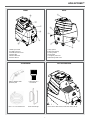
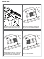
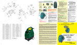
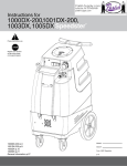
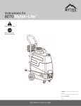
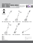
Instructions for
HP60 Spyder™
Please read before use.
Register your product
at http://www.mytee.
com/support/register
Model #
Set up p. 3
General information p. 6
Parts & pricing p. 9
Wiring diagram p. 11
Notes p.12
Serial #
Form # ADM-HP60
6-11
13655 Stowe Dr., Poway, Ca. 92064
1
2
HP60 SPYDER™
FRONT
BACK
7
1
2
3
12
4
11
5
8
6
10
9
1. Waist high controls
2. 2” Male Cuff-Lynx™
3. Female quick disconnect
4. Solution tank
5. Blower attachment
6. Solution tank lid
7. Easy open lid
8. Motor base housing
9. Locking casters
10. Vent guard
11. Single 25’ power cord
12. Bucket-high drain valve
FILL SOLUTION TANK
ACCESSORIES
8400 - 3” Stainless Steel
Upholstery Tool 8501- 15’ 1-1/4” Vac/Sol Hose
H122- Cuff-Lynx™
1 1/4” reducer
Lift lid to fill. For best results, fill with warm water (140° F).
H375- Hose Hanger
3
HP60 SPYDER™
ATTACH HOSES
PUMP
UM
P
PUM
TER
HEA
U
VAC
After the machine has been plugged into a 20 amp grounded
outlet, turn on pump. Key tool until upholstery tool releases a
steady flow.
Attach one end of a solution hose to a wand or other tool, the
other end to the Spyder’s™ front quick disconnect. Attach one
end of a vacuum hose to the tool, the other end to the Spyder’s™
Cuff-Lynx™ vacuum hose port.
VACUUM MOTOR
HEATER
UM
P
PUM
TER
HEA
UM
U
VAC
P
PUM
TER
HEA
U
VAC
Release tool trigger. Turn on heater. Wait 8 – 10 minutes for unit
to pre-heat. Once heated, re-key upholstery tool until hot water
begins flowing. Once hot water is flowing, release trigger and
pre-heat an additional 4 – 5 minutes.
Turn on vacuum motor and begin cleaning. For best results
make two dry passes to every wet pass.
4
HP60 SPYDER™
ENGLISH
BLOWER ATTACHMENT
RECOVERY TANK
Connect blower attachment for drying (optional).
.
Add
a defoamer in the recovery tank to reduce foam, prolonging
the life of the Spyder™ vacuum motor .
45 DEGREE SPOUT DRAIN
MYTEE® SYSTEM MAINTAINER
When the float shuts off vacuum, empty tank. Pull lever located at
the back of the machine to release water.
Weekly flushing of the solution system with Mytee® System
Maintainer helps keep lines clean and prevents chemical build-up,
improving pump life, performance and pressure.
5
GENERAL INFORMATION
Dear Customer:
Unpacking the Machine
Keep in mind that the HP60 Spyder™ is a machine, so neglect or abuse
will cause unnecessary damage and void the warranty. However with simple
maintenance the HP60 will give quality performance for many years to come.
Caution and Warnings
When the machine is delivered, carefully inspect the shipping carton and the
machine for damage. If damage is evident, save the shipping carton so that it can
be inspected by the carrier that delivered it. Contact the carrier immediately to file a
freight damage claim.
Congratulations on the purchase of your new HP60 Spyder™. As you are
already aware, the scene of the equipment world is becoming more high tech, and
we at Mytee Products Inc. strive to keep you on the cutting edge with superior
quality and technology.
Symbols
Mytee uses the symbols below to signal potentially dangerous conditions. Always
read this information carefully and take the necessary steps to protect personnel
and property.
If warranty questions arise, please consult your user manual or get in touch with
your distributor. If you have questions about maintenance, replacing parts or
ordering parts, please call an authorized Mytee Products Inc. Service Center.
To see an updated list, visit our website at www.mytee.com
Is used to warn of immediate hazards that will cause severe personal injury or death.
Before you begin cleaning, please read your manual thoroughly.
Sincerely,
Mytee Customer Care Dept.
Is used to call attention to a situation that could cause severe personal injury.
Grounding Instructions
This machine must be grounded. If it should malfunction or breakdown, grounding
provides a path of least resistance for electrical shock. This machine is equipped with
a cord having an equipment-grounding conductor and grounding plug. The plug must
be plugged into an appropriate outlet that is properly installed in accordance with all
local code and ordinances. Do not remove ground pin; if missing, replace plug before
use.
Is used to call attention to a situation that could cause minor personal injury or
damage to the machine or other property. When using an electrical appliance, basic
precautions should always be followed, including the following: Read all instructions
before using this machine. This product is intended for commercial use only.
To reduce the risk of fire, electrical shock, or injury:
1. Read all instructions before using equipment.
2. Use only as described in this manual. Use only manufacturer’s recommended
attachments.
3. Always unplug power cord from electrical outlet before attempting any adjustments
or repairs.
4. Do not unplug by pulling on cord. To unplug, grasp the plug, not the cord.
5. Do not pull or carry by cord. Do not close a door on cord or pull cord around sharp
edges or corners.
6. Do not run appliance over cord. Keep cord away from heated surfaces.
7. Do not use with damaged cord or plug. If cord is damaged, repair immediately.
8. Do not use outdoors or on wet surfaces and or standing water.
9. Always unplug or disconnect the appliance from power supply when not in use.
10. Do not allow to be used as a toy. Close attention is necessary when used by or
near children.
11. Do not use in areas where flammable or combustible material may be present.
12. Do not leave the unit exposed to harsh weather elements. Temperatures below
freezing may damage components and void warranty.
13. Use only the appropriate handles to move and lift unit. Do not use any other parts
of this machine for this purpose.
14. Keep hair, loose clothing, fingers, and all parts of the body away from all
openings and moving parts.
15. Use extra care when cleaning on stairs.
16. To reduce the risk of fire or electric shock, do not use this machine with a solidstate speed control device.
17. The voltage and frequency indicated on the name plate must correspond to the
wall receptacle supply voltage.
18. When cleaning and servicing the machine, local or national regulations may apply
to the safe disposal of liquids which may contain: chemicals, grease, oil, acid, alkalines, or other dangerous liquids.
19. Do not leave operating unattended.
Improper connection of the equipment-grounding conductor can result in a risk of
electric shock. Check with a qualified electrician or service person if you are in doubt
as to whether the outlet is properly grounded. Do not modify the plug provided with
the machine. If it will not fit the outlet, have a proper outlet installed by a qualified
electrician.
This appliance is for use on a nominal 120-volt circuit, and has a grounding plug
that looks like the plug illustrated in Figure 1 below. A temporary adapter illustrated
in Figures 2 and 3 may be used to connect this plug to a 2-pole receptacle as
shown in Figure 2 if a properly grounded outlet is not available. The temporary
adapter should be used only until a properly grounded outlet (Figure 1) can be
installed by a qualified electrician. The green colored rigid ear, tab or the like
extending from the adapter must be connected to a permanent ground such as a
properly grounded outlet box cover. Whenever the adapter is used, it must be held
in place by a metal screw. Grounding adapters are not approved for use in Canada.
Replace the plug if the grounding pin is damaged or broken.
The Green (or GreenYellow) wire in the cord is the grounding wire. When replacing
a plug, this wire must be attached to the grounding pin only.
DO NOT use extension cords.
Please Note for America use only
Grounded Outlet
Adapter
Metal
Screw
Grounding Pin
Grounded Outlet Box
Figure 1
Parts and Service
Figure 2
Filling the Solution Tank
Tab for Grounding
Screw
1. Fill the solution tank with the approved cleaning solution.
2. Do not fill up the solution tank completely: 1” should be left free at the top.
3. Typically, the solution should be a mixture of water and a cleaning chemical
appropriate for the type of job.
4. Always follow the dilution instructions on the chemical container label.
5. The temperature of the cleaning solution must not exceed 70oC/160oF.
Figure 3
Repairs, when required, should be performed by Mytee service personnel or Mytee
authorized Service Center using Mytee original replacement parts and accessories.
Call Mytee for repair parts or service. Please specify the Model and Serial Number
when discussing your machine.
Name Plate
Use only non-flammable liquid in this machine.
The Model and Serial Number of your machine are shown on the Nameplate on the
back panel of the machine. This information is needed when ordering repair parts
for the machine. Use the space provided on the front cover to note the Model and
Serial Number of your machine for future reference.
6
GENERAL INFORMATION
Setup
Maintenance Schedule
1. Open lid of solution tank. Fill solution with water or approved cleaning agent. For
best results, fill with warm water (140o).
Flammable materials can cause an explosion or fire. Do not use flammable solutions
or materials in tank(s).
FOR SAFETY: When using machine, follow mixing and handling instructions on
chemical containers.
ATTENTION: If using powdered cleaning chemicals, mix prior to adding.
Maintenance item
Daily
Clean and inspect Tanks
Clean and inspect Hoses
Check filters
Check power supply cable
Clean machine with all purpose cleaner and cloth
Check spray nozzles
Flush solution system with Mytee system maintainer
Remove and clean float shut-off screen from tank
Inspect vacuum hoses for holes and loose cuffs
x
x
x
x
x
Once a week
x
x
x
x
Trouble Shooting
2. Attach solution hose (located front of machine). NOTE: Make sure the quick
disconnect snap together firmly. As you do this, always inspect hoses for cracks or
fraying. Do not use if hoses are damaged.
3. Attach other end of solution hose to wand.
4. Attach vacuum hose to recovery tank.
5. Plug machine’s cord into a grounded wall outlet. FOR SAFETY: Do not operate
machine unless cord is properly grounded. FOR SAFETY: Do not operate machine
with the use of an extension cord.
6. Turn on pump. Key tool until you have a steady flow.
7. Release tool trigger. Turn on heater.
8. Wait 8–10 minutes for unit to pre-heat.
9. Re-key upholstery tool until hot water begins flowing.
10. Once hot water is flowing, release trigger and pre-heat an additional 4–5 minutes.
11. Turn on vacuum motor.
12. Begin cleaning. Make two dry passes to every wet pass.
13. For floor cleaning, unplug tool and attach floor wand.
14. Work away from cords to avoid damage.
15. Use a defoamer in your recovery tank.
16. To clean heavily soiled areas, repeat cleaning from different directions.
17. When float shuts off vacuum, empty tanks.
18. When work is complete, unplug cords and hoses.
19. Wrap and clean hoses. Clean all tanks.
There is no power.
1. Plug machine in proper outlet.
2. Check circuit breaker; reset circuit breaker, other items should not run on the
same circuit as machine. Outlet must be a 20-amp circuit.
Pump does not work properly.
1. Snap quick disconnects firmly together.
2. Check solution tank; may be empty.
3. Jets clogged, remove jet and flush clean.
4. Filters clogged, remove filters and rinse clean with water.
5. Heater is blocked; flush out with Mytee’s system maintainer.
6. If brass check valve is stuck replace valve.
7. Check pump wire. May need to reconnect wire.
8. Switch plate switch may need to be replaced.
9. If pump motor brushes are worn, replace pump.
Heater does not work properly.
1. If sensor mounted on the heater has popped, reset sensor by pushing in button.
2. Heating element may need to be replaced.
Vacuum motor does not work properly.
1. Check that hose is tightly connected.
2. Close drain hose valve completely.
3. Secure the vacuum tank tightly.
4. If ball float is shut off, empty vacuum tank of all wastewater.
5. Make sure ball float is firmly installed on the elbow.
6. If water is coming out of vacuum motor, use a low foaming detergent.
7. Clean upholstery tool or floor wand jets.
Pre-Operation
1. Vacuum carpet and upholstery and remove other debris.
2. Perform machine setup procedures.
3. Inspect power cord for damage.
Operation
Accessories (optional)
1. Turn pump switch on.
2. Pull up on tool lever to release air in the line. Hold lever until a steady flow of water
comes out of the wand.
3. Once pump is primed and there is pressure in the solution line, turn on heater switch
(if model is equipped with heater) and wait a few minutes for water to heat up.
4. Once water is heated, turn on vacuum and begin cleaning.
Note: When cleaning upholstery, always check manufacturer’s cleaning instructions.
2200 Airmover
3601 System Maintainer
2700 Mytee-Dry
8700 Crevice Tool
HP-Dry Vehicle Drying Kit
FAQs
Q: How much does the HP60 weigh and what are the shipping dimensions?
A: 69 Pounds - Box dimensions are 28 1/2” x 17 1/4” x 35 3/4”.
Must ship motor freight.
1. Work away from outlet and power cord to prevent cord damage.
2. Use a recommended foam control solution in the recovery tank to prevent vacuum
motor damage. Periodically check for excessive foam buildup in solution tank, and
recovery tank.
3. To clean heavily soiled areas, repeat cleaning path from different direction.
4. When ball float shuts off vacuum, it is time to empty the dirty water from the
recovery tank, and refill solution tank.
5. After cleaning, relieve water pressure from tool before disconnecting hose.
Squeeze trigger for five seconds after turning main power switch off.
Q: What comes standard with the HP60?
A: The HP60 comes with a hose hanger ( H375 ), a 25’ 12/3 Cord, 15’ 1-1/4”
Vacuum/Solution Hose ( 8501 ), Cuff-Lynx™ 1-1/4” reducer ( H122 ) and a
3” Stainless Steel Upholstery Tool ( 8400 ).
Q: Does Mytee recommend a tool for the machine?
A: A variety of tools can be used with the unit, including our 8390 wand, 8700 crevice
tool, and 8400 upholstery tool. Also our HP-Dry kit can be used for drying interiors
and exteriors.
After Use
1. Unplug.
2. Empty solution tank and rinse it with clean water.
3. Inspect hoses and replace if damaged.
4. Inspect solution filter. Clean or replace if damaged.
5. Store the machine in a clean, dry place.
6. Open recovery tank cover to promote air circulation.
Q: Where do I plug the machine in?
A: The HP60 requires a 20A grounded circuit. Please note: GFI outlets may trip
before the breaker setting.
Q: What is the proper pre heat cycle for the HP60?
A: Turn pump switch to the on position and prime pump through the solution hose
and the tool. Then turn the heater switch to the on position. Let the machine sit idle
for 8-10 minutes. Spray tool until you feel the hot water from the jet. Let machine sit
idle for an additional 3-5 minutes. This will insure the water in the heater and hoses
will be at the hottest point to start cleaning.
7
GENERAL INFORMATION
Q: Are the pumps re-buildable for the HP60?
A: Yes, both the seals and the pistons have repair kits available.
Please see the pump manual that shipped with your machine for the
maintenance schedule.
If any provision or portion of this limited warranty policy is found to be unenforceable,
then the remaining provisions and portions shall remain valid and enforceable.
If any provision or portion of this limited warranty policy is found to be limited by law,
then that provision or portion shall be construed to make it effective within the
bounds of law. For example, if there are legal limitations on the duration of warranties, the warranties made herein shall be construed to have the minimum duration
required by law, or, if there are legal limitations of exclusion of remedies, the exclusions made herein shall be construed to apply to the fullest extent possible without
violating the law.
Q: Is there anything I can do to increase the expected life of my machine?
A: Running the vacuum motors with the tank empty and lid off will allow excess
moisture in the vacs to dry off. You should also run a System Maintainer through
the system to keep the hoses, pump, and heater clean and free of debris.
Warranty
The validity, construction and performance of this warranty policy shall be governed
by the laws of the State of California, without respect to conflicts of laws principles.
The exclusive jurisdiction of any legal action arising from or related to this warranty
policy shall be in the State of California and no legal action shall be commenced
elsewhere.
MYTEE LIFETIME LIMITED WARRANTY POLICY
Mytee Products, Inc. endeavors to provide high quality products and product support
to its customers and therefore backs up all of its new products purchased from Mytee
Products Inc. (“Mytee”) or any authorized Mytee distributor/service center with this
lifetime limited warranty. This limited warranty begins on the date of the customer’s
purchase and is valid and available to the original purchaser with proof of purchase,
and is not transferable. Mytee’s products are for commercial use only and are not
intended for personal, family or household uses.
Return Material Authorization Procedure
It is the responsibility of any Authorized Service Center (ASC) or Distributor with
written authorization to ensure the Customers equipment is repaired as soon as
possible. Only Mytee Products Inc. or it’s authorized dealers with written authorization, service centers, and agents may make warranty repairs on these products. All
others do so at their own risk and expense.
HOUSING LIMITED LIFETIME WARRANTY: Mytee warrants for life that its rotationally-molded housings will be free from manufacturing defects. This warranty covers
the cost of replacement or repair only and does not cover shipping or labor costs.
The Distributor must follow Mytee Products, Inc. standard RMA procedure:
WEAR PARTS 90-DAY LIMITED WARRANTY: Mytee will replace all wear parts for
90 days from the date of original purchase. “Wear parts” are items which wear out
as a result of usage or the passage of time and are consumed despite attempts to
maintain them, such as gaskets, wheels, brass, cords, wires, electrical terminals,
hoses, switches, thermostats, plastisol parts, filters, bearings, brushes, solenoids, orings, bulbs, heating elements, castors, or other parts deemed wear items in Mytee’s
sole discretion. This warranty covers the cost of replacement only and does not cover
shipping or labor costs.
1. When a repair falls within the Warranty time period for a piece of equipment, the
Distributor will fill out a RMA/Warranty claim form. This form will act as a repair order
to replace any defective parts.
2. All defective parts must be returned to Mytee Products, Inc. with the RMA/claim
form for evaluation at the customer’s expense. This shipping is non-refundable. All
warranty claims are subject to an evaluation by Mytee Products, Inc. to determine if
warranty will be approved. Any credit for repair and/or parts will only be issued upon
evaluation and approval from Mytee Products, Inc.
PUMP, VACUUM MOTOR AND HEATER ONE-YEAR LIMITED WARRANTY: Mytee
warrants that pumps, vacuum and floor machine motors, and heaters will be free
from manufacturing defects, defects in workmanship, and defects in material for two
(1) year from the date of original purchase. This warranty does not apply and is void
if the pump, vacuum motor, or heater has worn brush motors, water damage, chemical build-up, chemical damage, or evidence of abuse, neglect or tampering. This
warranty covers the cost of replacement or repair only and does not cover shipping
or labor costs.
3. When Warranty is approved, the Distributor’s account will be credited for the
replacement part(s). Mytee Products, Inc. will ship the warranted replacement part(s)
to the Distributor prepaid. If Warranty is denied the Distributor’s account will not be
credited for any parts sent for this claim.
HOWEVER, OTHER THAN SET FORTH HEREIN, MYTEE GIVES NO WARRANTY,
EXPRESS OR IMPLIED, AS TO DESCRIPTION, QUALITY, MERCHANTABILITY,
FITNESS FOR ANY PARTICULAR PURPOSE, PRODUCTIVENESS, INFRINGEMENT, OR OTHER MATTER, OF ANY GOODS WHICH MYTEE SHALL SUPPLY.
THERE ARE NO WARRANTIES WHICH EXTEND BEYOND THE DESCRIPTION
ON THE FACE HEREOF. MYTEE SHALL IN NO WAY BE RESPONSIBLE FOR THE
PROPER USE AND APPLICATION OF THE GOODS. MYTEE NEITHER ASSUMES
NOR AUTHORIZES ANY OTHER PERSON TO ASSUME FOR MYTEE ANY OTHER
LIABILITY IN CONNECTION WITH THE SALE OF MYTEE’S GOODS. THIS LIMITED WARRANTY POLICY MAY BE CHANGED OR WITHDRAWN BY MYTEE AT
ANY TIME WITHOUT NOTICE.
LIMITATION OF DAMAGES: THE REMEDY OF REPLACEMENT OR REPAIR
OF ANY DEFECTIVE GOODS SHALL BE THE EXCLUSIVE REMEDY UNDER
ANY WARRANTY MADE BY MYTEE, WHETHER EXPRESS OR IMPLIED. IN NO
EVENT SHALL MYTEE BE LIABLE FOR ANY INCIDENTAL OR CONSEQUENTIAL
DAMAGES, PROPERTY DAMAGES, OR PERSONAL INJURIES.
All limited warranties are void for, and Mytee does not warrant in any way, any product that evidences misapplication, improper installation, abuse, lack of maintenance,
negligence in use or care, abnormal use, alteration of design, modification, use of
incompatible or corrosive chemicals, use in a rental service, and/or servicing, installation of parts, or repairs by anyone other than Mytee or a Mytee authorized distributor
or service center. Mytee may make changes in products it manufactures and markets
at any time; these changes are made without obligation to change, retrofit, or upgrade any product previously sold or manufactured.
Mytee has no obligation to honor the limited warranties set forth herein unless the
original purchaser, promptly upon discovering the warranty claim and prior to continuing to use the product, contacts Mytee or a Mytee authorized distributor or service
center to describe the claim and to receive and follow instructions for documenting
and resolving the claim. In addition, the purchaser must provide the product to which
the claim applies to Mytee or a Mytee authorized distributor or service center for a
thorough inspection. In addition, the purchaser must provide/return the product intact,
unmodified, with all of its original parts.
8
Order parts at: www.mytee.com/products/hp60-spyder-automotive-detail-extractor
9
H212
B107
60
H667
48
59
H202
47
B119
G001
46
58
H229
45
H201
H296
44
57
H343
43
H379
P791
42
56
H221
41
H316
H220
40
55
E531
39
H203
H458
38
G052
H768
37
54
H204
36
53
H330
35
H211
H501
52
G004
33
34
H213
H770
32
51
C302
31
P792
H300
30
H215
PH627-24
29
50
P735
49
PH628-18
22
28
H347
21
27
PH615-22
20
H217
B172
19
26
H185
18
B160
H210
17
H244
C305
16
PH633-03
B105
15
23
B136
14
25
AH184
13
24
B207
B108
12
AH156
E573
H903A
7
8
11
elbow, brass, 90 deg, 1/4"mpt x 1/4" fpt
E574
6
B103
H274
5
AH108S
E571
4
9
H528
3
10
heater, aluminum cast, single w/wrap & drilled holes
H230
2
DESCRIPTION
H273
1
nipple, brass, 1/4"m, hex
washer, 9/16"id x 1"od, flat, s/s
filter, strainer, 1/4"
bolt, 1/4-20 x 1/2", hex head, zinc
bracket, front, kodiak
bolt, 1/4-20 x 1-1/2" hex head, s/s
bolt, 1/4-20 x 1-1/4" hex head
washer, buna 1-1/8" od x 3/16" id
washer, 1/4"id x 1"od, flat, s/s
washer, 1/4" lock, s/s
nut, hex, 1/4-20 s/s
sol tank, spyder
caster, 3", Black Hub, Gray Tread
bolt, 1/4-20 x 3/4" hex head, s/s
gasket, inlet, 1.80" i.d.
fitting, inlet, pvc, 1-1/2", gray
guard, cooling fan, wire
screw, #10 x 5/8" hex head, zinc
base, spyder
nut, lock, 1/2" steel
fitting, strain relief, cord
power cord, end, 25', 12/3 black
nut, lock, 10-32, thin pattern
bolt, 1/4-20 x 3/4" serrated hex flange, zinc
bolt, 1/4-20 x 1-3/4" hex head, s/s
plate, single manifold, 6.5" x 9"
vac support, 3 stage, 4-1/16"
gasket, vacuum motor
bolt, 1/4-20 x 1/2" serrated hex flange, zinc
vac motor, 3 stage, 120V, tangential
cuff, black 1-1/2"
vac hose, 1-1/2", wire reinforced
manifold, single vac, no gasket
vac hose, 2", wire reinforced
clamp, hose, 2-1/4 dia
pipe, pvc, 1-1/2"
adapter, pvc, 1-1/2" fms x fmpt
adapter, brass, 1/2" barb x 3/8" fsw, ball end
clamp, hose, 5/16-29/32
sol hose, 1/2" kuri 100psi
elbow, brass, 90 deg, 1/2" barb x 3/8"mpt
screw, 10-32 x 1-1/4", phil flat full thread, black oxide
washer, 1/4" flat, s/s
pump, 120psi, demand, 115V
bushing, brass, 3/8"mpt x 1/4"
elbow, brass, 90 deg, 1/4" mpt x 1/4" mpt
hose, 3/8" x 14-1/2" (OAL), f surge
valve, brass, 1/4" check
elbow, brass, 90 deg, 1/4" fpt x 1/4" fpt
hose, 3/8" x 6.5", (OAL), f x fsw, surge, 1600psi
sol hose, 1/4" x 24 1/2", (OAL), f x fsw, 3000psi
Thermostat, 200°, Auto, 1/4"
Thermostat, 310°F ± 10°F, Manual, 1/4"
screw, 6 x 3/16, phil pan head, self tapping
heating rod, 600W, 115V
bracket, heater mounting, dual
screw, 10-32 x 1/2 phil pan
nut, kep, #10-32 zinc
PART NO.
ITEM
NO.
3
6
1
2
1
2
1
2
2
3
1
1
4
16
1
3
2
8
1
1
1
1
21
3
3
1
3
1
11
1
1
1
1
1
3
1
2
1
4
1
1
4
24
1
2
1
1
1
1
1
1
6
2
2
2
10
2
1
2
6
QTY.
MSRP
$3.19 ea
$0.99 ea
$3.99 ea
$0.99 ea
$3.99 ea
$0.99 ea
$0.99 ea
$1.99 ea
$0.99 ea
$0.99 ea
$0.99 ea
$103.99 ea
$14.99 ea
$0.99 ea
$2.99 ea
$5.99 ea
$2.99 ea
$0.99 ea
$106.99 ea
$1.99 ea
$3.19 ea
$52.99 ea
$0.99 ea
$0.99 ea
$0.99 ea
$7.99 ea
$4.99 ea
$8.99 ea
$0.99 ea
$140.99
$5.99 ea
$6.49/ft
$14.99 ea
$8.99/ft
$1.49 ea
$4.99/Ft
$4.99 ea
$3.49 ea
$1.99 ea
$8.99/ft
$9.49 ea
$0.99 ea
$0.99ea
$151.99 ea
$3.19 ea
$4.99 ea
$27.99 ea
$13.99 ea
$5.99 ea
$23.99 ea
$26.49 ea
$4.49 ea
$78.99 ea
$16.49 ea
$17.99 ea
$0.99 ea
$49.99 ea
$29.99 ea
$0.99 ea
$0.99 ea
E515
H636
H389
77
78
79
DESCRIPTION
DESCRIPTION
filter, bag, vac tank
gasket, strip, 3/4" x 36" x 1/8"
hanger, wire formed, hose
PART NO.
G010
G085
H375
screw, #10-32 x 1/2" SHCS, alloy
plate, switch, ml/trkr, 3 hole
switch, rocker, 2 position
bracket, "L" (all extracters)
spout, drain, 45 degree
valve, drain, 1-1/2"
elbow, inlet assy 1-1/2"
gasket, vac lid, 6.5" i.d 7.5" o.d
lid, vac, 6", clear
screw, #8 x 5/8 phil oval, s/s
float, 1.5", ball style
elbow, U, 180, 1-1/2", float
PIPE, PVC, 1-1/2" x 7-1/2" LG.
vac tank, spyder
bracket, rear, fb/spy
hose, 3/8" x 9" (OAL), f x f, surge, 1600psi
washer, nylon, 9/16id x 1-1/16od x .031
qd, brass, 1/4" f
adapter, brass, extender, 1/4" mpt x 1/4" fpt, hex
ITEMS NOT SHOWN:
H390A
H226
76
H225
A925
73
75
G060
72
74
G056
H304
71
H235
PH633-6
67
70
P793
66
69
H912
65
P755
AH157
64
68
B102
H413
63
B111
61
62
PART NO.
ITEM
NO.
2
2
1
QTY.
4
1
3
2
1
1
1
1
1
6
1
1
1
1
1
1
2
1
1
QTY.
MSRP
$10.99 ea
$4.99 ea
$9.99 ea
MSRP
$0.99 ea
$6.99 ea
$13.99 ea
$6.99 ea
$3.19 ea
$20.99 ea
$14.99 ea
$9.99 ea
$28.99 ea
$0.99 ea
$19.99 ea
$8.99 ea
$4.99/ft
$117.99 ea
$9.99 ea
$25.99 ea
$0.99 ea
$17.99 ea
$3.49 ea
HP60 SPYDER™ PARTS & PRICING
Part prices are subject to change.
10
A
B
C
D
E
F
5
6
8
8
4
7
3
2
1
8
9
10
To female q.d.
thru B103 (#9)
9
22
23
11
7
44
43
9
To filter in sol tank
thru B103 (#9)
7
21
12
20
13
14
15
16
19
1
17
45
47
18
38
To inlet on base
(#48)
18
48
24
42
6
6
25
26
41
27
26
40
29
30
39
38
28
26
5
37
5
18
36
34
33
32
38
35
49
18
56
To pump "IN"
thru B160 (#27)
55
31
16
51
57
50
51
4
52
53
53
9
59
60
59
58
4
52
54
62
61
59
63
60
63
59
32
59
60
64
9
59
32
3
To heater "OUT"
thru AH108S (#11)
9
65
3
24
67
68
79
66
69
78
2
45
77
45
46
2
32
70
NAME
J. Cash
76
72
DATE
10/26/10
THE INFORMATION CONTAINED IN THIS
DRAWING IS THE SOLE PROPERTY OF
MYTEE PRODUCTS, INC. ANY
REPRODUCTION IN PART OR AS A WHOLE
WITHOUT THE WRITTEN PERMISSION OF
MYTEE PRODUCTS, INC. IS PROHIBITED.
PROPRIETARY AND CONFIDENTIAL
CHECKED
DRAWN
32
71
75
1
SCALE: 1:5
DO NOT SCALE
DRAWING
HP60
REV
OD
SHEET 2 OF 2
Spyder
858-679-1191
SIZE DWG. NO.
D
74
mytee PRODUCTS, INC.
TITLE:
73
1
E
F
A
B
C
D
HP60 SPYDER™ PARTS & PRICING
Cord Input Primary
Entry Location, Top or Far Right
L2
GND
Black
Inline Conn.
Green
White
Black
L1
Green
SW-DPST
E515
Inline Conn.
Switch
Pressure
C305
Inline Conn.
White
Pressure Pump
L2
Black
2
Inline Conn.
Green
White
Black
Green
C302
Inline Conn.
SW-DPST
E515
Inline Conn.
Vacuum Motor 1
L2
GND
L1
Black
Blue
Black
White
3
L2
E571
Green
Legal
Size:
Number: 0000
SW-DPST
E515
Thermal Switch
E571
Heater 2
Revision: A
Date: 1/31/2011
Time: 4:44:13 PM Sheet 1 of 1
File: Z:\Engineering\GHI\GHI Projects\MYTEE\Mytee Schema
HP60
Title
SW-DPST
E515
Thermal Switch
L1
GND
L1
Black
Yellow
L2
White
Thermal Switch
Orange
Green
GND
White
Thermal Switch
L1
11
Orange
Green
GND
Heater 1
1
HP60 SPYDER™ WIRING DIAGRAM
Black
NOTES
Mytee Products Inc.
13655 Stowe Dr.
Poway, Ca. 92064
www.mytee.com
© 2013 Mytee Products Inc.
Printed in the U.S.A.
12