1
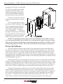
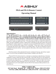
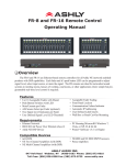
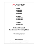
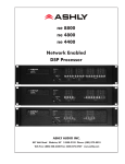
Ashly neWR-5 Remote Control User Reference Introduction The neWR-5 is a programmable ethernet based remote control unit for all Ashly NE (network enabled) products, including NE processors, NE power amplifiers, Pema amplifiers, and nX networked amplifiers. This remote brings control features such as preset recall/ scroll, mute, zone source selection, individual channel and matrix point level control, and logic output control throughout a building wherever there is a network connection. All programming is done across the network using Ashly Proteane software. FCC Compliance This device complies with part 15 of the FCC Rules for class A operation, and is subject to the following two conditions: 1. This device may not cause harmful interference. 2. This device must accept any interference received, including interference that may cause undesired operation. Features The neWR-5 is designed to mount into a standard earth grounded North America electrical wall box. A decora cover plate (not included) can be purchased at hardware stores to cover the neWR-5 electrical box and satisfy the aesthetic needs of the installation. Connecting and powering the neWR-5 requires Cat-5 ethernet cable and a IEEE 802.3af Power over Ethernet (PoE) switch, hub, or inline PoE injector. If PoE is unavailable, a 15-48VDC power supply capable of at least 2 watts per neWR-5 can be hard wired to a euroblock connector on the back of the remote. The RJ-45 connector has a green LED to indicate an Ethernet connection has been made, and a yellow LED to indicate data is being transferred. There is a hard-wired Lock-Out feature on the neWR-5, where the closing of a switch wired to the lockout euroblock renders all buttons inactive. The neWR-5 has six programmable function buttons which can light up green, red, or amber to display status. To the right of the function buttons is a pocket in the mylar overlay for a paper function label to be inserted. The two other buttons are used to adjust function parameters such as gain or preset number, and are indicated by the LED display. Hardware Installation The neWR-5 Ethernet control connection is made using an RJ-45 terminated eight conductor cable connected directly to a computer, or indirectly over a standard 10/100M Ethernet network. Maximum cable distance for Ethernet is 100 meters from the nearest hub or switch for copper Ashly Audio Inc 847 Holt Rd Webster NY 14580 585-872-0010 toll free 800-828-6308 fax 585-872-0739 www.ashly.com Operating Manual - neWR-5 Remote Control for NE Products twisted pair CAT5 cable. If using IEEE 802.3af PoE, no further power supply is required, otherwise connect a 1548VDC power supply to the neWR-5 via the labelled euroblock connector. PoE current draw is 38mA @48VDC. If desired, wire the Lock Out connector to an external remote or keyed switch. Upon connecting and powering up the system, the WR-5 will have a “heartbeat”, meaning an internal small green LED on the PCB (behind the display bezel) will be flashing. After power up, the LED displays “- -”. If there is a two-digit number showing in the display, that means the WR-5 has been previously programmed to control a zone and that number is the gain level for that zone. NOTE: For maximum protection against static shock disruptions to the neWR-5, mount it to an earth-grounded metal wall box, and be sure to earth-ground it’s metal cover plate as shown. This prevents incidental static discharge from flowing through the neWR-5 or it’s Ethernet cable, potentially disrupting the neWR-5. Do not rely on the Ethernet cable ground for earth ground. Protea NE Software Ashly NE products installed on the network will be automatically detected and displayed in the active device menu tree on the left side of the Protea NE software startup screen. The software scans for active NE devices every time it loads, but the user can manually scan at any time as well with <Scan For Devices> at the bottom of the network NE device listing. All NE devices continuously broadcast their availability to the software. All currently connected and active NE products are highlighted in green, while NE products which have been formerly installed but are currently off-line or unavailable show up in red. Individual NE products can be dragged onto the project canvas to simulate physical installation groups, but editing each product can be done from either the menu tree or the project canvas. Lines, rectangles, text, and image files can be added to create a custom virtual control screen along with NE products and individual control objects. To see all available canvas tools, right click anywhere over open canvas. Projects, including all device settings and canvas drawings, can be saved as a file. Checking <Design Mode> (right-click on canvas) allows placed objects to be moved around, while unchecking <Design Mode> locks objects in place. Once an image has been placed on the canvas, it must be deleted by hand if that device is no longer available to the software. Scanning for devices does not automatically remove images which may have been installed at one time but are now off line. To clear the canvas of all devices and drawn elements click <File - New>. Further neWR-5 help is available in Protea NE software by navigating through the online help menu. 2 Operating Manual - neWR-5 Remote Control for NE Products Main Control Surface The main control surface is where the neWR-5 is named, its target NE device gets selected, any zone definition occurs, and where the function buttons are programmed, The neWR-5 comes with all function buttons set to “Off”. Unlike the WR-5, changes must be saved to the neWR-5 before becoming effective. Not all of the button functions listed below are available on all NE products, for instance an amplifier will not have “matrix mixer” capability unless it has DSP installed, and some products do not have logic outputs. Protea NE software is able to determine which functions are available for neWR-5 control. 1) Off - No function assigned and the button’s LED remains unlit 2) Preset Recall - A single preset number is assigned to a button. When the button is pressed, the recalled preset number and the letters “PC” (Preset Change) are alternately flashed on the WR-5 for five seconds, also locking out any other WR-5 action for that time. 3) Preset Scroll Mode - A range of presets can be assigned to a function button which when selected, enables the up/down buttons to scroll through the available presets. Upon release of the up/ down button, the currently displayed preset will load. The function button will glow amber for the duration of the preset scroll operation. 4) Gain Control - Since there are many possible gain adjustment points within a given NE audio processing device, the neWR-5 displayed gain level is only a relative value. In other words, gain could be changed elsewhere in the target unit, independent from neWR-5 control. The neWR-5 can adjust gain from 0 to 99, and an upper and lower number limit can be set in the function range section to limit the maximum and minimum reach of that control. To control the gain within the target device’s input or output signal path, the neWR-5 remote gain function must first be inserted into a block in the unit’s DSP controls window. Gain Control over individual channel(s) - When a gain control button is assigned to control one or more individual channels, pressing that button will cause it to light amber, during which time the up/down buttons determine gain for the selected channels. If the up/down buttons remain idle for five seconds, the gain button becomes inactive until being pressed again. Gain Control over zone - If a zone output is active for that neWR-5, meaning one or more output checkboxes are selected within the neWR-5 Zone Setup mode, the output gain for that zone will be shown as the default numerical display, during which time the up/down buttons stay active for that zone’s overall gain control. If a button is assigned for individual input channel(s) gain control in addition to the neWR-5 being defined for output zone control, that button will turn amber when pressed, and both the neWR-5 up/down buttons and display will reflect the input channel(s) gain, reverting back to output zone gain after five seconds of inactivity. If there is no zone output assigned for the neWR-5, the display shows “--” as the default. 5) Channel Engage/Mute - A button can be configured to mute one or more inputs or outputs, or any combination of the two. The button is green when engaged and red when the selected channels are muted. 3 Operating Manual - neWR-5 Remote Control for NE Products 6) Zone Source Selection - This function is used to assign a button to select one or more inputs for the defined zone (Select Zone Outputs) under neWR-5 control. Any function button can have any combination of inputs as sources. A zone source selection button is green when selected, and red when unselected. When multiple zone source select buttons are assigned different or overlapping inputs, each button will simply add to or subtract from the other’s input selections. However, if the Exclusive Source Selection box is checked in the zone setup, only the currently selected button’s inputs will be used for that zone. The <Disable Zone Level Control> checkbox allows input source selections to be changed from the neWR-5, but not the overall output gain for that zone. The output gain can still be adjusted from the target device software, but the neWR-5 user is locked out from making output zone gain changes. 7) Logic Output Active High - This allows the user to toggle the Logic Output assigned pin to the button. The switch turns green when the output is high. 8) Logic Output Active Low- The switch turns green when the output is Low. 9) Matrix Mixer - This is used to select one or more inputs for the zone under neWR-5 control, but allows level control of that group at the dsp matrix mixer point instead of the output. Select one or more Zone Output(s) in the Zone Setup to use the Matrix Mixer function Security In addition to the hardware lockout available on the neWR-5, there are multiple user/multiple levels of software protection assignable to the neWR-5 within the Security tab, from full access to view only. The security data is stored within the neWR-5 itself, not Protea NE Software. Passwords are case sensitive. Be sure to write down the password and store in a convenient place for future reference. Network Properties Hardware, device, and device network configuration details are displayed in the network properties tab. This includes the current neWR-5 firmware revision. Flash Reprogram The firmware, meaning the internal program which runs on the neWR-5, can be updated easily over the network. Look in network properties for the current firmware revision. To obtain the latest firmware, visit the Ashly Web site, locate and save it to the computer, then run <Flash Reprogram> under the Device Options menu. The LED displays “Pr” during the reprogramming process. Factory Reset To restore factory default settings, a factory reset can be performed by connecting power to the unit while holding the top function button down for 10 seconds, during which time a countdown will occur on the LED display. Releasing the button at any time prior to completion of the countdown stops the process. Upon completion of the countdown, the LED displays “Fr” until the neWR-5 is reset. 4 Operating Manual - neWR-5 Remote Control for NE Products Ashly Audio Inc. LIMITED WARRANTY (USA ONLY) (Other countries please contact your respective distributor or dealer.) For units purchased in the USA, warranty service for this unit shall be provided by ASHLY AUDIO, INC. in accordance with the following warranty statement. ASHLY AUDIO, INC. warrants to the owner of this product that it will be free from defects in workmanship and materials for a period of FIVE years from the original-date-of-purchase. ASHLY AUDIO INC. will without charge, repair or replace at its discretion, any defective product or component parts upon prepaid delivery of the product to the ASHLY AUDIO, INC. factory service department, accompanied with a proof of original-date-of-purchase in the form of a valid sales receipt. This warranty gives you specific legal rights, and you may also have other rights, which vary from state to state. EXCLUSIONS: This warranty does not apply in the event of misuse, neglect, or as a result of unauthorized alterations or repairs made to the product. This warranty is void if the serial number is altered, defaced, or removed. ASHLY AUDIO, INC. reserves the right to make changes in design, or make additions to, or improvements upon, this product without any obligation to install the same on products previously manufactured. Any implied warranties, which may arise under the operation of state law, shall be effective only for FIVE years from the original-date-of-purchase of the product. ASHLY AUDIO, INC. shall be obligated to only correct defects in the product itself. ASHLY AUDIO, INC. is not liable for any damage or injury, which may result from, or be incidental to, or a consequence of, such defects. Some states do not allow limitations on how long an implied warranty lasts, or the exclusion, or limitation of incidental or consequential damages, so the above limitations or exclusions may not apply to you. OBTAINING WARRANTY SERVICE: For warranty service in the United States, please follow this procedure: 1) Return the product to ASHLY AUDIO, INC. freight prepaid, with a written statement describing the defect and application that the product is used in. ASHLY AUDIO, INC. will examine the product and perform any necessary service, including replacement of defective parts, at no further cost to you. 2) Ship your product to: ASHLY AUDIO, INC. Attention: Service Department 847 Holt Road Webster, NY 14580-9103 5 Operating Manual - neWR-5 Remote Control for NE Products (This page intentionally left blank) Ashly Audio Inc 847 Holt Rd Webster NY 14580 585-872-0010 toll free 800-828-6308 fax 585-872-0739 www.ashly.com 2013 by Ashly Audio Corporation. All rights reserved worldwide. Printed in USA 0313 R3