1
XLM H25
Owner’s manual
R9010100
R5976690/04
24/02/2005
Barco nv Events
Noordlaan 5, B-8520 Kuurne
Phone: +32 56.36.89.70
Fax: +32 56.36.88.24
E-mail: [email protected]
Visit us at the web: www.barco.com
Printed in Belgium
Changes
Barco provides this manual ’as is’ without warranty of any kind, either expressed or implied, including but not limited to the implied warranties or merchantability and fitness for a particular purpose. Barco may make improvements and/or changes to the product(s) and/or the
program(s) described in this publication at any time without notice.
This publication could contain technical inaccuracies or typographical errors. Changes are periodically made to the information in this
publication; these changes are incorporated in new editions of this publication.
Copyright ©
All rights reserved. No part of this document may be copied, reproduced or translated. It shall not otherwise be recorded, transmitted or
stored in a retrieval system without the prior written consent of Barco.
Guarantee and Compensation
Barco provides a guarantee relating to perfect manufacturing as part of the legally stipulated terms of guarantee. On receipt, the purchaser
must immediately inspect all delivered goods for damage incurred during transport, as well as for material and manufacturing faults Barco
must be informed immediately in writing of any complaints.
The period of guarantee begins on the date of transfer of risks, in the case of special systems and software on the date of commissioning,
at latest 30 days after the transfer of risks. In the event of justified notice of compliant, Barco can repair the fault or provide a replacement
at its own discretion within an appropriate period. If this measure proves to be impossible or unsuccessful, the purchaser can demand a
reduction in the purchase price or cancellation of the contract. All other claims, in particular those relating to compensation for direct or
indirect damage, and also damage attributed to the operation of software as well as to other services provided by Barco, being a component
of the system or independent service, will be deemed invalid provided the damage is not proven to be attributed to the absence of properties
guaranteed in writing or due to the intent or gross negligence or part of Barco.
If the purchaser or a third party carries out modifications or repairs on goods delivered by Barco, or if the goods are handled incorrectly,
in particular if the systems are commissioned operated incorrectly or if, after the transfer of risks, the goods are subject to influences not
agreed upon in the contract, all guarantee claims of the purchaser will be rendered invalid. Not included in the guarantee coverage are
system failures which are attributed to programs or special electronic circuitry provided by the purchaser, e.g. interfaces. Normal wear as
well as normal maintenance are not subject to the guarantee provided by Barco either.
The environmental conditions as well as the servicing and maintenance regulations specified in the this manual must be complied with by
the customer.
Trademarks
Brand and product names mentioned in this manual may be trademarks, registered trademarks or copyrights of their respective holders.
All brand and product names mentioned in this manual serve as comments or examples and are not to be understood as advertising for
the products or their manufactures.
Table of contents
TABLE OF CONTENTS
1. Packaging and Dimensions . . . . . . . . . . . . . . . . . . . . . . . . . . . . . . . . . . . . . . . . . . . . . . . . . . . . . . . . . . . . . . . . . . . . . . . . . . . . . . . . . . . . . . . 5
1.1
1.2
1.3
1.4
1.5
Projector Packaging. . . . . . . . . . . . . . . . . . . . . . . . . . . . . . . . . . . . . . . . . . . . . . . . . . . . . . . . . . . . . . . . . . . . . . . . . . . . . . . . . . . . . . . . . . . . . . . . . . . . . . . . . . . . . . . . . . .
Lens Packaging . . . . . . . . . . . . . . . . . . . . . . . . . . . . . . . . . . . . . . . . . . . . . . . . . . . . . . . . . . . . . . . . . . . . . . . . . . . . . . . . . . . . . . . . . . . . . . . . . . . . . . . . . . . . . . . . . . . . . . .
Lamp House Packaging. . . . . . . . . . . . . . . . . . . . . . . . . . . . . . . . . . . . . . . . . . . . . . . . . . . . . . . . . . . . . . . . . . . . . . . . . . . . . . . . . . . . . . . . . . . . . . . . . . . . . . . . . . . . . . .
Box content . . . . . . . . . . . . . . . . . . . . . . . . . . . . . . . . . . . . . . . . . . . . . . . . . . . . . . . . . . . . . . . . . . . . . . . . . . . . . . . . . . . . . . . . . . . . . . . . . . . . . . . . . . . . . . . . . . . . . . . . . . . .
Dimensions . . . . . . . . . . . . . . . . . . . . . . . . . . . . . . . . . . . . . . . . . . . . . . . . . . . . . . . . . . . . . . . . . . . . . . . . . . . . . . . . . . . . . . . . . . . . . . . . . . . . . . . . . . . . . . . . . . . . . . . . . . . .
5
5
5
6
6
2. Installation Guidelines. . . . . . . . . . . . . . . . . . . . . . . . . . . . . . . . . . . . . . . . . . . . . . . . . . . . . . . . . . . . . . . . . . . . . . . . . . . . . . . . . . . . . . . . . . . . . . 9
2.1
2.2
2.3
2.4
2.5
General guidelines . . . . . . . . . . . . . . . . . . . . . . . . . . . . . . . . . . . . . . . . . . . . . . . . . . . . . . . . . . . . . . . . . . . . . . . . . . . . . . . . . . . . . . . . . . . . . . . . . . . . . . . . . . . . . . . . . . . . 9
Restricted Access Location . . . . . . . . . . . . . . . . . . . . . . . . . . . . . . . . . . . . . . . . . . . . . . . . . . . . . . . . . . . . . . . . . . . . . . . . . . . . . . . . . . . . . . . . . . . . . . . . . . . . . . . . . . 10
Projector configuration . . . . . . . . . . . . . . . . . . . . . . . . . . . . . . . . . . . . . . . . . . . . . . . . . . . . . . . . . . . . . . . . . . . . . . . . . . . . . . . . . . . . . . . . . . . . . . . . . . . . . . . . . . . . . . . 11
Safety Area around projector . . . . . . . . . . . . . . . . . . . . . . . . . . . . . . . . . . . . . . . . . . . . . . . . . . . . . . . . . . . . . . . . . . . . . . . . . . . . . . . . . . . . . . . . . . . . . . . . . . . . . . . . 13
Lenses . . . . . . . . . . . . . . . . . . . . . . . . . . . . . . . . . . . . . . . . . . . . . . . . . . . . . . . . . . . . . . . . . . . . . . . . . . . . . . . . . . . . . . . . . . . . . . . . . . . . . . . . . . . . . . . . . . . . . . . . . . . . . . . . 13
2.5.1 Lenses . . . . . . . . . . . . . . . . . . . . . . . . . . . . . . . . . . . . . . . . . . . . . . . . . . . . . . . . . . . . . . . . . . . . . . . . . . . . . . . . . . . . . . . . . . . . . . . . . . . . . . . . . . . . . . . . . . . . . . . . . 13
2.5.2 Lens formulas. . . . . . . . . . . . . . . . . . . . . . . . . . . . . . . . . . . . . . . . . . . . . . . . . . . . . . . . . . . . . . . . . . . . . . . . . . . . . . . . . . . . . . . . . . . . . . . . . . . . . . . . . . . . . . . . . . 14
2.5.3 Lens installation . . . . . . . . . . . . . . . . . . . . . . . . . . . . . . . . . . . . . . . . . . . . . . . . . . . . . . . . . . . . . . . . . . . . . . . . . . . . . . . . . . . . . . . . . . . . . . . . . . . . . . . . . . . . . . . 14
2.6 Mounting the lamp house . . . . . . . . . . . . . . . . . . . . . . . . . . . . . . . . . . . . . . . . . . . . . . . . . . . . . . . . . . . . . . . . . . . . . . . . . . . . . . . . . . . . . . . . . . . . . . . . . . . . . . . . . . . . 15
2.7 Transporting the projector. . . . . . . . . . . . . . . . . . . . . . . . . . . . . . . . . . . . . . . . . . . . . . . . . . . . . . . . . . . . . . . . . . . . . . . . . . . . . . . . . . . . . . . . . . . . . . . . . . . . . . . . . . . . 17
2.8 Battery Insertion in the Remote Control . . . . . . . . . . . . . . . . . . . . . . . . . . . . . . . . . . . . . . . . . . . . . . . . . . . . . . . . . . . . . . . . . . . . . . . . . . . . . . . . . . . . . . . . . . . . . 17
2.9 Battery insertion in the Rugged remote control . . . . . . . . . . . . . . . . . . . . . . . . . . . . . . . . . . . . . . . . . . . . . . . . . . . . . . . . . . . . . . . . . . . . . . . . . . . . . . . . . . . . . 18
2.10 Charging the batteries of the rugged remote control. . . . . . . . . . . . . . . . . . . . . . . . . . . . . . . . . . . . . . . . . . . . . . . . . . . . . . . . . . . . . . . . . . . . . . . . . . . . . . . . 19
2.10.1 Preparing the charger . . . . . . . . . . . . . . . . . . . . . . . . . . . . . . . . . . . . . . . . . . . . . . . . . . . . . . . . . . . . . . . . . . . . . . . . . . . . . . . . . . . . . . . . . . . . . . . . . . . . . . . . . 19
2.10.2 Charging the batteries . . . . . . . . . . . . . . . . . . . . . . . . . . . . . . . . . . . . . . . . . . . . . . . . . . . . . . . . . . . . . . . . . . . . . . . . . . . . . . . . . . . . . . . . . . . . . . . . . . . . . . . . . 19
2.10.3 Power save mode . . . . . . . . . . . . . . . . . . . . . . . . . . . . . . . . . . . . . . . . . . . . . . . . . . . . . . . . . . . . . . . . . . . . . . . . . . . . . . . . . . . . . . . . . . . . . . . . . . . . . . . . . . . . . 20
2.11 Stacking Two Projectors . . . . . . . . . . . . . . . . . . . . . . . . . . . . . . . . . . . . . . . . . . . . . . . . . . . . . . . . . . . . . . . . . . . . . . . . . . . . . . . . . . . . . . . . . . . . . . . . . . . . . . . . . . . . . 20
2.12 Rigging points and clamps . . . . . . . . . . . . . . . . . . . . . . . . . . . . . . . . . . . . . . . . . . . . . . . . . . . . . . . . . . . . . . . . . . . . . . . . . . . . . . . . . . . . . . . . . . . . . . . . . . . . . . . . . . . 21
3. Connections. . . . . . . . . . . . . . . . . . . . . . . . . . . . . . . . . . . . . . . . . . . . . . . . . . . . . . . . . . . . . . . . . . . . . . . . . . . . . . . . . . . . . . . . . . . . . . . . . . . . . . . . . 23
3.1
3.2
3.3
Power connection . . . . . . . . . . . . . . . . . . . . . . . . . . . . . . . . . . . . . . . . . . . . . . . . . . . . . . . . . . . . . . . . . . . . . . . . . . . . . . . . . . . . . . . . . . . . . . . . . . . . . . . . . . . . . . . . . . . . 23
Connection facilities . . . . . . . . . . . . . . . . . . . . . . . . . . . . . . . . . . . . . . . . . . . . . . . . . . . . . . . . . . . . . . . . . . . . . . . . . . . . . . . . . . . . . . . . . . . . . . . . . . . . . . . . . . . . . . . . . . 25
Input source connection. . . . . . . . . . . . . . . . . . . . . . . . . . . . . . . . . . . . . . . . . . . . . . . . . . . . . . . . . . . . . . . . . . . . . . . . . . . . . . . . . . . . . . . . . . . . . . . . . . . . . . . . . . . . . . 26
3.3.1 Introduction . . . . . . . . . . . . . . . . . . . . . . . . . . . . . . . . . . . . . . . . . . . . . . . . . . . . . . . . . . . . . . . . . . . . . . . . . . . . . . . . . . . . . . . . . . . . . . . . . . . . . . . . . . . . . . . . . . . . 26
3.3.2 Removing and Inserting an input module . . . . . . . . . . . . . . . . . . . . . . . . . . . . . . . . . . . . . . . . . . . . . . . . . . . . . . . . . . . . . . . . . . . . . . . . . . . . . . . . . . . . . 26
3.3.3 DVI input module . . . . . . . . . . . . . . . . . . . . . . . . . . . . . . . . . . . . . . . . . . . . . . . . . . . . . . . . . . . . . . . . . . . . . . . . . . . . . . . . . . . . . . . . . . . . . . . . . . . . . . . . . . . . . . 27
3.3.4 SDI input module . . . . . . . . . . . . . . . . . . . . . . . . . . . . . . . . . . . . . . . . . . . . . . . . . . . . . . . . . . . . . . . . . . . . . . . . . . . . . . . . . . . . . . . . . . . . . . . . . . . . . . . . . . . . . . 27
3.3.5 HDSDI input module. . . . . . . . . . . . . . . . . . . . . . . . . . . . . . . . . . . . . . . . . . . . . . . . . . . . . . . . . . . . . . . . . . . . . . . . . . . . . . . . . . . . . . . . . . . . . . . . . . . . . . . . . . . 28
3.3.6 YUV / RG(s)B input module . . . . . . . . . . . . . . . . . . . . . . . . . . . . . . . . . . . . . . . . . . . . . . . . . . . . . . . . . . . . . . . . . . . . . . . . . . . . . . . . . . . . . . . . . . . . . . . . . . . 29
3.3.7 RGB analog input module . . . . . . . . . . . . . . . . . . . . . . . . . . . . . . . . . . . . . . . . . . . . . . . . . . . . . . . . . . . . . . . . . . . . . . . . . . . . . . . . . . . . . . . . . . . . . . . . . . . . . 29
3.3.8 CVBS / S-VID input module . . . . . . . . . . . . . . . . . . . . . . . . . . . . . . . . . . . . . . . . . . . . . . . . . . . . . . . . . . . . . . . . . . . . . . . . . . . . . . . . . . . . . . . . . . . . . . . . . . . 30
3.3.9 Dummy input module . . . . . . . . . . . . . . . . . . . . . . . . . . . . . . . . . . . . . . . . . . . . . . . . . . . . . . . . . . . . . . . . . . . . . . . . . . . . . . . . . . . . . . . . . . . . . . . . . . . . . . . . . . 30
3.4 Communication connection . . . . . . . . . . . . . . . . . . . . . . . . . . . . . . . . . . . . . . . . . . . . . . . . . . . . . . . . . . . . . . . . . . . . . . . . . . . . . . . . . . . . . . . . . . . . . . . . . . . . . . . . . . 31
3.4.1 RS232/422 IN/OUT Serial network . . . . . . . . . . . . . . . . . . . . . . . . . . . . . . . . . . . . . . . . . . . . . . . . . . . . . . . . . . . . . . . . . . . . . . . . . . . . . . . . . . . . . . . . . . . 31
3.4.2 Ethernet connection . . . . . . . . . . . . . . . . . . . . . . . . . . . . . . . . . . . . . . . . . . . . . . . . . . . . . . . . . . . . . . . . . . . . . . . . . . . . . . . . . . . . . . . . . . . . . . . . . . . . . . . . . . . 32
3.4.3 Hardwired remote to CTRL 1. . . . . . . . . . . . . . . . . . . . . . . . . . . . . . . . . . . . . . . . . . . . . . . . . . . . . . . . . . . . . . . . . . . . . . . . . . . . . . . . . . . . . . . . . . . . . . . . . . 32
3.4.4 Bi-directional communication port, CTRL 3. . . . . . . . . . . . . . . . . . . . . . . . . . . . . . . . . . . . . . . . . . . . . . . . . . . . . . . . . . . . . . . . . . . . . . . . . . . . . . . . . . . 33
3.5 Monitor output . . . . . . . . . . . . . . . . . . . . . . . . . . . . . . . . . . . . . . . . . . . . . . . . . . . . . . . . . . . . . . . . . . . . . . . . . . . . . . . . . . . . . . . . . . . . . . . . . . . . . . . . . . . . . . . . . . . . . . . . 35
4. Getting Started. . . . . . . . . . . . . . . . . . . . . . . . . . . . . . . . . . . . . . . . . . . . . . . . . . . . . . . . . . . . . . . . . . . . . . . . . . . . . . . . . . . . . . . . . . . . . . . . . . . . . . 37
4.1
4.2
4.3
4.4
4.5
4.6
4.7
4.8
4.9
Terminology overview RCU and local keypad. . . . . . . . . . . . . . . . . . . . . . . . . . . . . . . . . . . . . . . . . . . . . . . . . . . . . . . . . . . . . . . . . . . . . . . . . . . . . . . . . . . . . . . 37
Terminology overview Rugged remote control . . . . . . . . . . . . . . . . . . . . . . . . . . . . . . . . . . . . . . . . . . . . . . . . . . . . . . . . . . . . . . . . . . . . . . . . . . . . . . . . . . . . . . 39
Switching on the projector . . . . . . . . . . . . . . . . . . . . . . . . . . . . . . . . . . . . . . . . . . . . . . . . . . . . . . . . . . . . . . . . . . . . . . . . . . . . . . . . . . . . . . . . . . . . . . . . . . . . . . . . . . . 40
Lamp runtime . . . . . . . . . . . . . . . . . . . . . . . . . . . . . . . . . . . . . . . . . . . . . . . . . . . . . . . . . . . . . . . . . . . . . . . . . . . . . . . . . . . . . . . . . . . . . . . . . . . . . . . . . . . . . . . . . . . . . . . . . 40
Switching to standby . . . . . . . . . . . . . . . . . . . . . . . . . . . . . . . . . . . . . . . . . . . . . . . . . . . . . . . . . . . . . . . . . . . . . . . . . . . . . . . . . . . . . . . . . . . . . . . . . . . . . . . . . . . . . . . . . 40
Switching off . . . . . . . . . . . . . . . . . . . . . . . . . . . . . . . . . . . . . . . . . . . . . . . . . . . . . . . . . . . . . . . . . . . . . . . . . . . . . . . . . . . . . . . . . . . . . . . . . . . . . . . . . . . . . . . . . . . . . . . . . . 41
Using the RCU . . . . . . . . . . . . . . . . . . . . . . . . . . . . . . . . . . . . . . . . . . . . . . . . . . . . . . . . . . . . . . . . . . . . . . . . . . . . . . . . . . . . . . . . . . . . . . . . . . . . . . . . . . . . . . . . . . . . . . . 41
Using the Rugged remote control. . . . . . . . . . . . . . . . . . . . . . . . . . . . . . . . . . . . . . . . . . . . . . . . . . . . . . . . . . . . . . . . . . . . . . . . . . . . . . . . . . . . . . . . . . . . . . . . . . . . 42
Projector address . . . . . . . . . . . . . . . . . . . . . . . . . . . . . . . . . . . . . . . . . . . . . . . . . . . . . . . . . . . . . . . . . . . . . . . . . . . . . . . . . . . . . . . . . . . . . . . . . . . . . . . . . . . . . . . . . . . . 42
4.9.1 Address setting . . . . . . . . . . . . . . . . . . . . . . . . . . . . . . . . . . . . . . . . . . . . . . . . . . . . . . . . . . . . . . . . . . . . . . . . . . . . . . . . . . . . . . . . . . . . . . . . . . . . . . . . . . . . . . . . 42
4.9.2 Displaying and Programming addresses into the RCU . . . . . . . . . . . . . . . . . . . . . . . . . . . . . . . . . . . . . . . . . . . . . . . . . . . . . . . . . . . . . . . . . . . . . . 43
4.9.3 Displaying and Programming addresses into the rugged remote control. . . . . . . . . . . . . . . . . . . . . . . . . . . . . . . . . . . . . . . . . . . . . . . . . . . . 43
4.10 Controlling the projector. . . . . . . . . . . . . . . . . . . . . . . . . . . . . . . . . . . . . . . . . . . . . . . . . . . . . . . . . . . . . . . . . . . . . . . . . . . . . . . . . . . . . . . . . . . . . . . . . . . . . . . . . . . . . . 44
4.11 Quick lens adjustment. . . . . . . . . . . . . . . . . . . . . . . . . . . . . . . . . . . . . . . . . . . . . . . . . . . . . . . . . . . . . . . . . . . . . . . . . . . . . . . . . . . . . . . . . . . . . . . . . . . . . . . . . . . . . . . . 45
4.11.1 Direct Lens Adjustment (RCU) . . . . . . . . . . . . . . . . . . . . . . . . . . . . . . . . . . . . . . . . . . . . . . . . . . . . . . . . . . . . . . . . . . . . . . . . . . . . . . . . . . . . . . . . . . . . . . . . 45
4.11.2 Lens adjustment via menus . . . . . . . . . . . . . . . . . . . . . . . . . . . . . . . . . . . . . . . . . . . . . . . . . . . . . . . . . . . . . . . . . . . . . . . . . . . . . . . . . . . . . . . . . . . . . . . . . . . 45
5. Getting used to the menu structure. . . . . . . . . . . . . . . . . . . . . . . . . . . . . . . . . . . . . . . . . . . . . . . . . . . . . . . . . . . . . . . . . . . . . . . . . . . . . 47
5.1
5.2
How to start up the menus . . . . . . . . . . . . . . . . . . . . . . . . . . . . . . . . . . . . . . . . . . . . . . . . . . . . . . . . . . . . . . . . . . . . . . . . . . . . . . . . . . . . . . . . . . . . . . . . . . . . . . . . . . . 47
Using the Dialog boxes . . . . . . . . . . . . . . . . . . . . . . . . . . . . . . . . . . . . . . . . . . . . . . . . . . . . . . . . . . . . . . . . . . . . . . . . . . . . . . . . . . . . . . . . . . . . . . . . . . . . . . . . . . . . . . 47
6. Adjustment Mode. . . . . . . . . . . . . . . . . . . . . . . . . . . . . . . . . . . . . . . . . . . . . . . . . . . . . . . . . . . . . . . . . . . . . . . . . . . . . . . . . . . . . . . . . . . . . . . . . . . 49
6.1
6.2
6.3
Adjustment mode overview . . . . . . . . . . . . . . . . . . . . . . . . . . . . . . . . . . . . . . . . . . . . . . . . . . . . . . . . . . . . . . . . . . . . . . . . . . . . . . . . . . . . . . . . . . . . . . . . . . . . . . . . . . 49
Start up of the Adjustment mode . . . . . . . . . . . . . . . . . . . . . . . . . . . . . . . . . . . . . . . . . . . . . . . . . . . . . . . . . . . . . . . . . . . . . . . . . . . . . . . . . . . . . . . . . . . . . . . . . . . . 49
File Service . . . . . . . . . . . . . . . . . . . . . . . . . . . . . . . . . . . . . . . . . . . . . . . . . . . . . . . . . . . . . . . . . . . . . . . . . . . . . . . . . . . . . . . . . . . . . . . . . . . . . . . . . . . . . . . . . . . . . . . . . . . 50
R5976690 XLM H25 24/02/2005
1
Table of contents
6.4
6.5
6.6
6.7
6.3.1 Possible file manipulations . . . . . . . . . . . . . . . . . . . . . . . . . . . . . . . . . . . . . . . . . . . . . . . . . . . . . . . . . . . . . . . . . . . . . . . . . . . . . . . . . . . . . . . . . . . . . . . . . . . . 50
6.3.2 Start up. . . . . . . . . . . . . . . . . . . . . . . . . . . . . . . . . . . . . . . . . . . . . . . . . . . . . . . . . . . . . . . . . . . . . . . . . . . . . . . . . . . . . . . . . . . . . . . . . . . . . . . . . . . . . . . . . . . . . . . . . 50
6.3.3 Load file . . . . . . . . . . . . . . . . . . . . . . . . . . . . . . . . . . . . . . . . . . . . . . . . . . . . . . . . . . . . . . . . . . . . . . . . . . . . . . . . . . . . . . . . . . . . . . . . . . . . . . . . . . . . . . . . . . . . . . . . 51
6.3.4 Edit file . . . . . . . . . . . . . . . . . . . . . . . . . . . . . . . . . . . . . . . . . . . . . . . . . . . . . . . . . . . . . . . . . . . . . . . . . . . . . . . . . . . . . . . . . . . . . . . . . . . . . . . . . . . . . . . . . . . . . . . . . 51
6.3.4.1 Start up . . . . . . . . . . . . . . . . . . . . . . . . . . . . . . . . . . . . . . . . . . . . . . . . . . . . . . . . . . . . . . . . . . . . . . . . . . . . . . . . . . . . . . . . . . . . . . . . . . . . . . . . . . . . . . . . . . 51
6.3.4.2 Changing the settings. . . . . . . . . . . . . . . . . . . . . . . . . . . . . . . . . . . . . . . . . . . . . . . . . . . . . . . . . . . . . . . . . . . . . . . . . . . . . . . . . . . . . . . . . . . . . . . . . . . 52
6.3.4.3 Correct value . . . . . . . . . . . . . . . . . . . . . . . . . . . . . . . . . . . . . . . . . . . . . . . . . . . . . . . . . . . . . . . . . . . . . . . . . . . . . . . . . . . . . . . . . . . . . . . . . . . . . . . . . . . . 52
6.3.5 Rename . . . . . . . . . . . . . . . . . . . . . . . . . . . . . . . . . . . . . . . . . . . . . . . . . . . . . . . . . . . . . . . . . . . . . . . . . . . . . . . . . . . . . . . . . . . . . . . . . . . . . . . . . . . . . . . . . . . . . . . . 54
6.3.6 Copy . . . . . . . . . . . . . . . . . . . . . . . . . . . . . . . . . . . . . . . . . . . . . . . . . . . . . . . . . . . . . . . . . . . . . . . . . . . . . . . . . . . . . . . . . . . . . . . . . . . . . . . . . . . . . . . . . . . . . . . . . . . 55
6.3.7 Delete . . . . . . . . . . . . . . . . . . . . . . . . . . . . . . . . . . . . . . . . . . . . . . . . . . . . . . . . . . . . . . . . . . . . . . . . . . . . . . . . . . . . . . . . . . . . . . . . . . . . . . . . . . . . . . . . . . . . . . . . . . 56
6.3.8 File Options . . . . . . . . . . . . . . . . . . . . . . . . . . . . . . . . . . . . . . . . . . . . . . . . . . . . . . . . . . . . . . . . . . . . . . . . . . . . . . . . . . . . . . . . . . . . . . . . . . . . . . . . . . . . . . . . . . . . 56
Picture Tuning . . . . . . . . . . . . . . . . . . . . . . . . . . . . . . . . . . . . . . . . . . . . . . . . . . . . . . . . . . . . . . . . . . . . . . . . . . . . . . . . . . . . . . . . . . . . . . . . . . . . . . . . . . . . . . . . . . . . . . . . 57
6.4.1 Start up. . . . . . . . . . . . . . . . . . . . . . . . . . . . . . . . . . . . . . . . . . . . . . . . . . . . . . . . . . . . . . . . . . . . . . . . . . . . . . . . . . . . . . . . . . . . . . . . . . . . . . . . . . . . . . . . . . . . . . . . . 57
6.4.2 Color Temperature . . . . . . . . . . . . . . . . . . . . . . . . . . . . . . . . . . . . . . . . . . . . . . . . . . . . . . . . . . . . . . . . . . . . . . . . . . . . . . . . . . . . . . . . . . . . . . . . . . . . . . . . . . . . . 57
6.4.2.1 Color Temperature selection. . . . . . . . . . . . . . . . . . . . . . . . . . . . . . . . . . . . . . . . . . . . . . . . . . . . . . . . . . . . . . . . . . . . . . . . . . . . . . . . . . . . . . . . . . . . 57
6.4.2.2 Custom color temperature . . . . . . . . . . . . . . . . . . . . . . . . . . . . . . . . . . . . . . . . . . . . . . . . . . . . . . . . . . . . . . . . . . . . . . . . . . . . . . . . . . . . . . . . . . . . . . 58
6.4.3 Gamma . . . . . . . . . . . . . . . . . . . . . . . . . . . . . . . . . . . . . . . . . . . . . . . . . . . . . . . . . . . . . . . . . . . . . . . . . . . . . . . . . . . . . . . . . . . . . . . . . . . . . . . . . . . . . . . . . . . . . . . . 58
6.4.4 Noise Reduction . . . . . . . . . . . . . . . . . . . . . . . . . . . . . . . . . . . . . . . . . . . . . . . . . . . . . . . . . . . . . . . . . . . . . . . . . . . . . . . . . . . . . . . . . . . . . . . . . . . . . . . . . . . . . . . 59
6.4.5 Input Balance . . . . . . . . . . . . . . . . . . . . . . . . . . . . . . . . . . . . . . . . . . . . . . . . . . . . . . . . . . . . . . . . . . . . . . . . . . . . . . . . . . . . . . . . . . . . . . . . . . . . . . . . . . . . . . . . . . 59
6.4.5.1 Introduction to Input Balance . . . . . . . . . . . . . . . . . . . . . . . . . . . . . . . . . . . . . . . . . . . . . . . . . . . . . . . . . . . . . . . . . . . . . . . . . . . . . . . . . . . . . . . . . . . 59
6.4.5.2 Adjusting the input balance . . . . . . . . . . . . . . . . . . . . . . . . . . . . . . . . . . . . . . . . . . . . . . . . . . . . . . . . . . . . . . . . . . . . . . . . . . . . . . . . . . . . . . . . . . . . . 61
6.4.5.3 Input balance for YUV signals . . . . . . . . . . . . . . . . . . . . . . . . . . . . . . . . . . . . . . . . . . . . . . . . . . . . . . . . . . . . . . . . . . . . . . . . . . . . . . . . . . . . . . . . . . 62
Window Adjustment . . . . . . . . . . . . . . . . . . . . . . . . . . . . . . . . . . . . . . . . . . . . . . . . . . . . . . . . . . . . . . . . . . . . . . . . . . . . . . . . . . . . . . . . . . . . . . . . . . . . . . . . . . . . . . . . . . 63
6.5.1 Start up. . . . . . . . . . . . . . . . . . . . . . . . . . . . . . . . . . . . . . . . . . . . . . . . . . . . . . . . . . . . . . . . . . . . . . . . . . . . . . . . . . . . . . . . . . . . . . . . . . . . . . . . . . . . . . . . . . . . . . . . . 63
6.5.2 Select Source . . . . . . . . . . . . . . . . . . . . . . . . . . . . . . . . . . . . . . . . . . . . . . . . . . . . . . . . . . . . . . . . . . . . . . . . . . . . . . . . . . . . . . . . . . . . . . . . . . . . . . . . . . . . . . . . . . 63
6.5.3 Size Adjustment . . . . . . . . . . . . . . . . . . . . . . . . . . . . . . . . . . . . . . . . . . . . . . . . . . . . . . . . . . . . . . . . . . . . . . . . . . . . . . . . . . . . . . . . . . . . . . . . . . . . . . . . . . . . . . . 64
6.5.4 Window Position . . . . . . . . . . . . . . . . . . . . . . . . . . . . . . . . . . . . . . . . . . . . . . . . . . . . . . . . . . . . . . . . . . . . . . . . . . . . . . . . . . . . . . . . . . . . . . . . . . . . . . . . . . . . . . . 65
6.5.5 Z-order . . . . . . . . . . . . . . . . . . . . . . . . . . . . . . . . . . . . . . . . . . . . . . . . . . . . . . . . . . . . . . . . . . . . . . . . . . . . . . . . . . . . . . . . . . . . . . . . . . . . . . . . . . . . . . . . . . . . . . . . . 66
6.5.6 Color Key . . . . . . . . . . . . . . . . . . . . . . . . . . . . . . . . . . . . . . . . . . . . . . . . . . . . . . . . . . . . . . . . . . . . . . . . . . . . . . . . . . . . . . . . . . . . . . . . . . . . . . . . . . . . . . . . . . . . . . 66
6.5.6.1 Color Key activation. . . . . . . . . . . . . . . . . . . . . . . . . . . . . . . . . . . . . . . . . . . . . . . . . . . . . . . . . . . . . . . . . . . . . . . . . . . . . . . . . . . . . . . . . . . . . . . . . . . . . 67
6.5.6.2 Set up of the color for color key . . . . . . . . . . . . . . . . . . . . . . . . . . . . . . . . . . . . . . . . . . . . . . . . . . . . . . . . . . . . . . . . . . . . . . . . . . . . . . . . . . . . . . . . 67
6.5.6.3 Color key range . . . . . . . . . . . . . . . . . . . . . . . . . . . . . . . . . . . . . . . . . . . . . . . . . . . . . . . . . . . . . . . . . . . . . . . . . . . . . . . . . . . . . . . . . . . . . . . . . . . . . . . . . 68
6.5.6.4 Color key algorithm . . . . . . . . . . . . . . . . . . . . . . . . . . . . . . . . . . . . . . . . . . . . . . . . . . . . . . . . . . . . . . . . . . . . . . . . . . . . . . . . . . . . . . . . . . . . . . . . . . . . . 68
6.5.6.5 Color key palette set up. . . . . . . . . . . . . . . . . . . . . . . . . . . . . . . . . . . . . . . . . . . . . . . . . . . . . . . . . . . . . . . . . . . . . . . . . . . . . . . . . . . . . . . . . . . . . . . . . 69
6.5.7 Alpha Blending. . . . . . . . . . . . . . . . . . . . . . . . . . . . . . . . . . . . . . . . . . . . . . . . . . . . . . . . . . . . . . . . . . . . . . . . . . . . . . . . . . . . . . . . . . . . . . . . . . . . . . . . . . . . . . . . . 69
6.5.8 No Signal. . . . . . . . . . . . . . . . . . . . . . . . . . . . . . . . . . . . . . . . . . . . . . . . . . . . . . . . . . . . . . . . . . . . . . . . . . . . . . . . . . . . . . . . . . . . . . . . . . . . . . . . . . . . . . . . . . . . . . . 71
6.5.9 Exit the Window adjustment menus. . . . . . . . . . . . . . . . . . . . . . . . . . . . . . . . . . . . . . . . . . . . . . . . . . . . . . . . . . . . . . . . . . . . . . . . . . . . . . . . . . . . . . . . . . . 71
Layout Adjustment . . . . . . . . . . . . . . . . . . . . . . . . . . . . . . . . . . . . . . . . . . . . . . . . . . . . . . . . . . . . . . . . . . . . . . . . . . . . . . . . . . . . . . . . . . . . . . . . . . . . . . . . . . . . . . . . . . . 72
6.6.1 Start up. . . . . . . . . . . . . . . . . . . . . . . . . . . . . . . . . . . . . . . . . . . . . . . . . . . . . . . . . . . . . . . . . . . . . . . . . . . . . . . . . . . . . . . . . . . . . . . . . . . . . . . . . . . . . . . . . . . . . . . . . 72
6.6.2 Load Layout. . . . . . . . . . . . . . . . . . . . . . . . . . . . . . . . . . . . . . . . . . . . . . . . . . . . . . . . . . . . . . . . . . . . . . . . . . . . . . . . . . . . . . . . . . . . . . . . . . . . . . . . . . . . . . . . . . . . 72
6.6.3 Rename Layout . . . . . . . . . . . . . . . . . . . . . . . . . . . . . . . . . . . . . . . . . . . . . . . . . . . . . . . . . . . . . . . . . . . . . . . . . . . . . . . . . . . . . . . . . . . . . . . . . . . . . . . . . . . . . . . . 73
6.6.4 Delete layout . . . . . . . . . . . . . . . . . . . . . . . . . . . . . . . . . . . . . . . . . . . . . . . . . . . . . . . . . . . . . . . . . . . . . . . . . . . . . . . . . . . . . . . . . . . . . . . . . . . . . . . . . . . . . . . . . . . 73
6.6.5 Add a window to a layout. . . . . . . . . . . . . . . . . . . . . . . . . . . . . . . . . . . . . . . . . . . . . . . . . . . . . . . . . . . . . . . . . . . . . . . . . . . . . . . . . . . . . . . . . . . . . . . . . . . . . . 74
6.6.6 Remove a window in a layout . . . . . . . . . . . . . . . . . . . . . . . . . . . . . . . . . . . . . . . . . . . . . . . . . . . . . . . . . . . . . . . . . . . . . . . . . . . . . . . . . . . . . . . . . . . . . . . . . 74
6.6.7 Edit window . . . . . . . . . . . . . . . . . . . . . . . . . . . . . . . . . . . . . . . . . . . . . . . . . . . . . . . . . . . . . . . . . . . . . . . . . . . . . . . . . . . . . . . . . . . . . . . . . . . . . . . . . . . . . . . . . . . . 75
6.6.8 Keystone adjustment . . . . . . . . . . . . . . . . . . . . . . . . . . . . . . . . . . . . . . . . . . . . . . . . . . . . . . . . . . . . . . . . . . . . . . . . . . . . . . . . . . . . . . . . . . . . . . . . . . . . . . . . . . 75
6.6.9 Blanking adjustment . . . . . . . . . . . . . . . . . . . . . . . . . . . . . . . . . . . . . . . . . . . . . . . . . . . . . . . . . . . . . . . . . . . . . . . . . . . . . . . . . . . . . . . . . . . . . . . . . . . . . . . . . . . 76
6.6.10 Input locking . . . . . . . . . . . . . . . . . . . . . . . . . . . . . . . . . . . . . . . . . . . . . . . . . . . . . . . . . . . . . . . . . . . . . . . . . . . . . . . . . . . . . . . . . . . . . . . . . . . . . . . . . . . . . . . . . . . 77
Scenergix . . . . . . . . . . . . . . . . . . . . . . . . . . . . . . . . . . . . . . . . . . . . . . . . . . . . . . . . . . . . . . . . . . . . . . . . . . . . . . . . . . . . . . . . . . . . . . . . . . . . . . . . . . . . . . . . . . . . . . . . . . . . . 77
6.7.1 Introduction . . . . . . . . . . . . . . . . . . . . . . . . . . . . . . . . . . . . . . . . . . . . . . . . . . . . . . . . . . . . . . . . . . . . . . . . . . . . . . . . . . . . . . . . . . . . . . . . . . . . . . . . . . . . . . . . . . . . 78
6.7.2 Preparations . . . . . . . . . . . . . . . . . . . . . . . . . . . . . . . . . . . . . . . . . . . . . . . . . . . . . . . . . . . . . . . . . . . . . . . . . . . . . . . . . . . . . . . . . . . . . . . . . . . . . . . . . . . . . . . . . . . 78
6.7.3 ScenergiX . . . . . . . . . . . . . . . . . . . . . . . . . . . . . . . . . . . . . . . . . . . . . . . . . . . . . . . . . . . . . . . . . . . . . . . . . . . . . . . . . . . . . . . . . . . . . . . . . . . . . . . . . . . . . . . . . . . . . . 78
6.7.4 ScenergiX overlap zone (horizontal scenergix). . . . . . . . . . . . . . . . . . . . . . . . . . . . . . . . . . . . . . . . . . . . . . . . . . . . . . . . . . . . . . . . . . . . . . . . . . . . . . . 79
6.7.5 ScenergiX overlap zone (vertical scenergix) . . . . . . . . . . . . . . . . . . . . . . . . . . . . . . . . . . . . . . . . . . . . . . . . . . . . . . . . . . . . . . . . . . . . . . . . . . . . . . . . . 80
6.7.6 ScenergiX size adjustment . . . . . . . . . . . . . . . . . . . . . . . . . . . . . . . . . . . . . . . . . . . . . . . . . . . . . . . . . . . . . . . . . . . . . . . . . . . . . . . . . . . . . . . . . . . . . . . . . . . . 81
6.7.7 Adjusting the black level of the images . . . . . . . . . . . . . . . . . . . . . . . . . . . . . . . . . . . . . . . . . . . . . . . . . . . . . . . . . . . . . . . . . . . . . . . . . . . . . . . . . . . . . . . 82
7. Installation . . . . . . . . . . . . . . . . . . . . . . . . . . . . . . . . . . . . . . . . . . . . . . . . . . . . . . . . . . . . . . . . . . . . . . . . . . . . . . . . . . . . . . . . . . . . . . . . . . . . . . . . . . . 85
7.1
7.2
7.3
7.4
7.5
7.6
7.7
7.8
2
Start up of the installation mode . . . . . . . . . . . . . . . . . . . . . . . . . . . . . . . . . . . . . . . . . . . . . . . . . . . . . . . . . . . . . . . . . . . . . . . . . . . . . . . . . . . . . . . . . . . . . . . . . . . . . 85
Input slots. . . . . . . . . . . . . . . . . . . . . . . . . . . . . . . . . . . . . . . . . . . . . . . . . . . . . . . . . . . . . . . . . . . . . . . . . . . . . . . . . . . . . . . . . . . . . . . . . . . . . . . . . . . . . . . . . . . . . . . . . . . . . 85
Configuration . . . . . . . . . . . . . . . . . . . . . . . . . . . . . . . . . . . . . . . . . . . . . . . . . . . . . . . . . . . . . . . . . . . . . . . . . . . . . . . . . . . . . . . . . . . . . . . . . . . . . . . . . . . . . . . . . . . . . . . . . 86
Lens. . . . . . . . . . . . . . . . . . . . . . . . . . . . . . . . . . . . . . . . . . . . . . . . . . . . . . . . . . . . . . . . . . . . . . . . . . . . . . . . . . . . . . . . . . . . . . . . . . . . . . . . . . . . . . . . . . . . . . . . . . . . . . . . . . . 86
7.4.1 Lens adjustment . . . . . . . . . . . . . . . . . . . . . . . . . . . . . . . . . . . . . . . . . . . . . . . . . . . . . . . . . . . . . . . . . . . . . . . . . . . . . . . . . . . . . . . . . . . . . . . . . . . . . . . . . . . . . . . 86
7.4.2 Lens files . . . . . . . . . . . . . . . . . . . . . . . . . . . . . . . . . . . . . . . . . . . . . . . . . . . . . . . . . . . . . . . . . . . . . . . . . . . . . . . . . . . . . . . . . . . . . . . . . . . . . . . . . . . . . . . . . . . . . . . 88
7.4.2.1 Run a lens file . . . . . . . . . . . . . . . . . . . . . . . . . . . . . . . . . . . . . . . . . . . . . . . . . . . . . . . . . . . . . . . . . . . . . . . . . . . . . . . . . . . . . . . . . . . . . . . . . . . . . . . . . . . 88
7.4.2.2 Save lens settings. . . . . . . . . . . . . . . . . . . . . . . . . . . . . . . . . . . . . . . . . . . . . . . . . . . . . . . . . . . . . . . . . . . . . . . . . . . . . . . . . . . . . . . . . . . . . . . . . . . . . . . 88
7.4.2.3 Rename lens file . . . . . . . . . . . . . . . . . . . . . . . . . . . . . . . . . . . . . . . . . . . . . . . . . . . . . . . . . . . . . . . . . . . . . . . . . . . . . . . . . . . . . . . . . . . . . . . . . . . . . . . . 89
7.4.2.4 Copy lens file . . . . . . . . . . . . . . . . . . . . . . . . . . . . . . . . . . . . . . . . . . . . . . . . . . . . . . . . . . . . . . . . . . . . . . . . . . . . . . . . . . . . . . . . . . . . . . . . . . . . . . . . . . . . 89
7.4.2.5 Delete lens file . . . . . . . . . . . . . . . . . . . . . . . . . . . . . . . . . . . . . . . . . . . . . . . . . . . . . . . . . . . . . . . . . . . . . . . . . . . . . . . . . . . . . . . . . . . . . . . . . . . . . . . . . . 89
Tilt adjustment . . . . . . . . . . . . . . . . . . . . . . . . . . . . . . . . . . . . . . . . . . . . . . . . . . . . . . . . . . . . . . . . . . . . . . . . . . . . . . . . . . . . . . . . . . . . . . . . . . . . . . . . . . . . . . . . . . . . . . . . 90
Internal Patterns. . . . . . . . . . . . . . . . . . . . . . . . . . . . . . . . . . . . . . . . . . . . . . . . . . . . . . . . . . . . . . . . . . . . . . . . . . . . . . . . . . . . . . . . . . . . . . . . . . . . . . . . . . . . . . . . . . . . . . 90
Buttons . . . . . . . . . . . . . . . . . . . . . . . . . . . . . . . . . . . . . . . . . . . . . . . . . . . . . . . . . . . . . . . . . . . . . . . . . . . . . . . . . . . . . . . . . . . . . . . . . . . . . . . . . . . . . . . . . . . . . . . . . . . . . . . 91
Macros . . . . . . . . . . . . . . . . . . . . . . . . . . . . . . . . . . . . . . . . . . . . . . . . . . . . . . . . . . . . . . . . . . . . . . . . . . . . . . . . . . . . . . . . . . . . . . . . . . . . . . . . . . . . . . . . . . . . . . . . . . . . . . . . 92
7.8.1 Run a macro . . . . . . . . . . . . . . . . . . . . . . . . . . . . . . . . . . . . . . . . . . . . . . . . . . . . . . . . . . . . . . . . . . . . . . . . . . . . . . . . . . . . . . . . . . . . . . . . . . . . . . . . . . . . . . . . . . . 92
7.8.2 Edit a Macro . . . . . . . . . . . . . . . . . . . . . . . . . . . . . . . . . . . . . . . . . . . . . . . . . . . . . . . . . . . . . . . . . . . . . . . . . . . . . . . . . . . . . . . . . . . . . . . . . . . . . . . . . . . . . . . . . . . 93
7.8.3 Rename a macro file . . . . . . . . . . . . . . . . . . . . . . . . . . . . . . . . . . . . . . . . . . . . . . . . . . . . . . . . . . . . . . . . . . . . . . . . . . . . . . . . . . . . . . . . . . . . . . . . . . . . . . . . . . 94
R5976690 XLM H25 24/02/2005
Table of contents
7.8.4
7.8.5
7.8.6
Copy a macro file . . . . . . . . . . . . . . . . . . . . . . . . . . . . . . . . . . . . . . . . . . . . . . . . . . . . . . . . . . . . . . . . . . . . . . . . . . . . . . . . . . . . . . . . . . . . . . . . . . . . . . . . . . . . . . 95
Delete a macro file. . . . . . . . . . . . . . . . . . . . . . . . . . . . . . . . . . . . . . . . . . . . . . . . . . . . . . . . . . . . . . . . . . . . . . . . . . . . . . . . . . . . . . . . . . . . . . . . . . . . . . . . . . . . . 95
Create a macro file . . . . . . . . . . . . . . . . . . . . . . . . . . . . . . . . . . . . . . . . . . . . . . . . . . . . . . . . . . . . . . . . . . . . . . . . . . . . . . . . . . . . . . . . . . . . . . . . . . . . . . . . . . . . 96
8. Service . . . . . . . . . . . . . . . . . . . . . . . . . . . . . . . . . . . . . . . . . . . . . . . . . . . . . . . . . . . . . . . . . . . . . . . . . . . . . . . . . . . . . . . . . . . . . . . . . . . . . . . . . . . . . . . 97
8.1
8.2
8.3
8.4
8.5
8.6
8.7
8.8
8.9
Start up of the service menu . . . . . . . . . . . . . . . . . . . . . . . . . . . . . . . . . . . . . . . . . . . . . . . . . . . . . . . . . . . . . . . . . . . . . . . . . . . . . . . . . . . . . . . . . . . . . . . . . . . . . . . . . 97
Identification . . . . . . . . . . . . . . . . . . . . . . . . . . . . . . . . . . . . . . . . . . . . . . . . . . . . . . . . . . . . . . . . . . . . . . . . . . . . . . . . . . . . . . . . . . . . . . . . . . . . . . . . . . . . . . . . . . . . . . . . . . 97
Change Projector Address – Common Address . . . . . . . . . . . . . . . . . . . . . . . . . . . . . . . . . . . . . . . . . . . . . . . . . . . . . . . . . . . . . . . . . . . . . . . . . . . . . . . . . . . . 98
Communication. . . . . . . . . . . . . . . . . . . . . . . . . . . . . . . . . . . . . . . . . . . . . . . . . . . . . . . . . . . . . . . . . . . . . . . . . . . . . . . . . . . . . . . . . . . . . . . . . . . . . . . . . . . . . . . . . . . . . . . 99
8.4.1 Baud rate Setting . . . . . . . . . . . . . . . . . . . . . . . . . . . . . . . . . . . . . . . . . . . . . . . . . . . . . . . . . . . . . . . . . . . . . . . . . . . . . . . . . . . . . . . . . . . . . . . . . . . . . . . . . . . . . . 99
8.4.2 Serial Interface setting. . . . . . . . . . . . . . . . . . . . . . . . . . . . . . . . . . . . . . . . . . . . . . . . . . . . . . . . . . . . . . . . . . . . . . . . . . . . . . . . . . . . . . . . . . . . . . . . . . . . . . . . . 99
8.4.3 RS422 Termination . . . . . . . . . . . . . . . . . . . . . . . . . . . . . . . . . . . . . . . . . . . . . . . . . . . . . . . . . . . . . . . . . . . . . . . . . . . . . . . . . . . . . . . . . . . . . . . . . . . . . . . . . . .100
8.4.4 Network Configuration . . . . . . . . . . . . . . . . . . . . . . . . . . . . . . . . . . . . . . . . . . . . . . . . . . . . . . . . . . . . . . . . . . . . . . . . . . . . . . . . . . . . . . . . . . . . . . . . . . . . . . . .100
Date and time setup. . . . . . . . . . . . . . . . . . . . . . . . . . . . . . . . . . . . . . . . . . . . . . . . . . . . . . . . . . . . . . . . . . . . . . . . . . . . . . . . . . . . . . . . . . . . . . . . . . . . . . . . . . . . . . . . .101
Lamp. . . . . . . . . . . . . . . . . . . . . . . . . . . . . . . . . . . . . . . . . . . . . . . . . . . . . . . . . . . . . . . . . . . . . . . . . . . . . . . . . . . . . . . . . . . . . . . . . . . . . . . . . . . . . . . . . . . . . . . .. . . . . . . . .102
Dimming-CLO . . . . . . . . . . . . . . . . . . . . . . . . . . . . . . . . . . . . . . . . . . . . . . . . . . . . . . . . . . . . . . . . . . . . . . . . . . . . . . . . . . . . . . . . . . . . . . . . . . . . . . . . . . . . . . . . . . . . . . .102
Convergence . . . . . . . . . . . . . . . . . . . . . . . . . . . . . . . . . . . . . . . . . . . . . . . . . . . . . . . . . . . . . . . . . . . . . . . . . . . . . . . . . . . . . . . . . . . . . . . . . . . . . . . . . . . . . . . . . . . . . . . .104
Diagnosis . . . . . . . . . . . . . . . . . . . . . . . . . . . . . . . . . . . . . . . . . . . . . . . . . . . . . . . . . . . . . . . . . . . . . . . . . . . . . . . . . . . . . . . . . . . . . . . . . . . . . . . . . . . . . . . . . . . . . . . . . . . .105
8.9.1 Start up. . . . . . . . . . . . . . . . . . . . . . . . . . . . . . . . . . . . . . . . . . . . . . . . . . . . . . . . . . . . . . . . . . . . . . . . . . . . . . . . . . . . . . . . . . . . . . . . . . . . . . . . . . . . . . . . . . . . . . . .105
8.9.2 Errors. . . . . . . . . . . . . . . . . . . . . . . . . . . . . . . . . . . . . . . . . . . . . . . . . . . . . . . . . . . . . . . . . . . . . . . . . . . . . . . . . . . . . . . . . . . . . . . . . . . . . . . . . . . . . . . . . . . . . . . . . .105
8.9.3 Voltages . . . . . . . . . . . . . . . . . . . . . . . . . . . . . . . . . . . . . . . . . . . . . . . . . . . . . . . . . . . . . . . . . . . . . . . . . . . . . . . . . . . . . . . . . . . . . . . . . . . . . . . . . . . . . . . . . . . . . . .105
8.9.4 Temperatures . . . . . . . . . . . . . . . . . . . . . . . . . . . . . . . . . . . . . . . . . . . . . . . . . . . . . . . . . . . . . . . . . . . . . . . . . . . . . . . . . . . . . . . . . . . . . . . . . . . . . . . . . . . . . . . . .106
8.9.5 Fan speeds . . . . . . . . . . . . . . . . . . . . . . . . . . . . . . . . . . . . . . . . . . . . . . . . . . . . . . . . . . . . . . . . . . . . . . . . . . . . . . . . . . . . . . . . . . . . . . . . . . . . . . . . . . . . . . . . . . .106
8.9.6 Versions . . . . . . . . . . . . . . . . . . . . . . . . . . . . . . . . . . . . . . . . . . . . . . . . . . . . . . . . . . . . . . . . . . . . . . . . . . . . . . . . . . . . . . . . . . . . . . . . . . . . . . . . . . . . . . . . . . . . . . .107
A. Specifications . . . . . . . . . . . . . . . . . . . . . . . . . . . . . . . . . . . . . . . . . . . . . . . . . . . . . . . . . . . . . . . . . . . . . . . . . . . . . . . . . . . . . . . . . . . . . . . . . . . . . 109
A.1
XLM H25 Specifications. . . . . . . . . . . . . . . . . . . . . . . . . . . . . . . . . . . . . . . . . . . . . . . . . . . . . . . . . . . . . . . . . . . . . . . . . . . . . . . . . . . . . . . . . . . . . . . . . . . . . . . . . . . . .109
B. Standard Source Set up files . . . . . . . . . . . . . . . . . . . . . . . . . . . . . . . . . . . . . . . . . . . . . . . . . . . . . . . . . . . . . . . . . . . . . . . . . . . . . . . . . . . .111
B.1
Table overview . . . . . . . . . . . . . . . . . . . . . . . . . . . . . . . . . . . . . . . . . . . . . . . . . . . . . . . . . . . . . . . . . . . . . . . . . . . . . . . . . . . . . . . . . . . . . . . . . . . . . . . . . . . . . . . . . . . . . . 111
C. Maintenance . . . . . . . . . . . . . . . . . . . . . . . . . . . . . . . . . . . . . . . . . . . . . . . . . . . . . . . . . . . . . . . . . . . . . . . . . . . . . . . . . . . . . . . . . . . . . . . . . . . . . . . 115
C.1 Pressure check of cooling liquid circuit . . . . . . . . . . . . . . . . . . . . . . . . . . . . . . . . . . . . . . . . . . . . . . . . . . . . . . . . . . . . . . . . . . . . . . . . . . . . . . . . . . . . . . . . . . . . . 115
C.2 Cleaning the dust filters . . . . . . . . . . . . . . . . . . . . . . . . . . . . . . . . . . . . . . . . . . . . . . . . . . . . . . . . . . . . . . . . . . . . . . . . . . . . . . . . . . . . . . . . . . . . . . . . . . . . . . . . . . . . . 116
C.3 Cleaning the lens . . . . . . . . . . . . . . . . . . . . . . . . . . . . . . . . . . . . . . . . . . . . . . . . . . . . . . . . . . . . . . . . . . . . . . . . . . . . . . . . . . . . . . . . . . . . . . . . . . . . . . . . . . . . . . . . . . . . 118
Glossary . . . . . . . . . . . . . . . . . . . . . . . . . . . . . . . . . . . . . . . . . . . . . . . . . . . . . . . . . . . . . . . . . . . . . . . . . . . . . . . . . . . . . . . . . . . . . . . . . . . . . . . . . . . . . . . 119
Index. . . . . . . . . . . . . . . . . . . . . . . . . . . . . . . . . . . . . . . . . . . . . . . . . . . . . . . . . . . . . . . . . . . . . . . . . . . . . . . . . . . . . . . . . . . . . . . . . . . . . . . . . . . . . . . . . . . . 121
R5976690 XLM H25 24/02/2005
3
Table of contents
4
R5976690 XLM H25 24/02/2005
1. Packaging and Dimensions
1. PACKAGING AND DIMENSIONS
1.1 Projector Packaging
Way of Packaging
The projector is packed in a carton box. To provide protection during transportation, the projector is surrounded with foam. The
package is secured with banding and fastening clips.
To unpack
1. Release the fastening clips.
2. Remove the banding. Handle as shown in the drawing. (image 1-1)
3. Take the projector out of its shipping carton and place it on a table.
PULL
TO OPE
Image 1-1
Save the original shipping carton and packing material, they will be necessary if you ever have to ship your
projector. For maximum protection, repack your projector as it was originally packed at the factory.
CAUTION:
Never transport the projector with the lens mounted on it !
Always remove the lens before transporting the projector.
1.2 Lens Packaging
Way of Packaging
Lenses are supplied as an individual item.
They are packed in a carton.
1.3 Lamp House Packaging
Way of Packaging
The lamp house is supplied as an individual item.
They are packed in a carton.
Never transport the projector with the lamp mounted inside the projector.
R5976690 XLM H25 24/02/2005
5
1. Packaging and Dimensions
1.4 Box content
Content
•
1 XLM H25 projector (weight 180 kg) without lamp house and lens.
•
1 remote control unit (RCU) + 2 batteries
•
1 rugged remote control
•
1 owners manual
•
1 safety manual
•
1 female plug P3 + NE 400V (red)
•
1 female plug P3 + E 250V (blue)
1.5 Dimensions
Dimensions are given without lens.
Side view
176 80
1050
80 176
1563
Image 1-2
Side view
6
R5976690 XLM H25 24/02/2005
1. Packaging and Dimensions
327
15
598
636
Front view
210
669
810
Image 1-3
Front view
Top view
468
27,5
1130
27,5
Image 1-4
Top view
R5976690 XLM H25 24/02/2005
7
1. Packaging and Dimensions
8
R5976690 XLM H25 24/02/2005
2. Installation Guidelines
2. INSTALLATION GUIDELINES
Overview
•
General guidelines
•
Restricted Access Location
•
Projector configuration
•
Safety Area around projector
•
Lenses
•
Mounting the lamp house
•
Transporting the projector
•
Battery Insertion in the Remote Control
•
Battery insertion in the Rugged remote control
•
Charging the batteries of the rugged remote control
•
Stacking Two Projectors
•
Rigging points and clamps
2.1 General guidelines
WARNING:
Before installing the projector, read first the safety instructions.
Ambient Temperature Conditions.
Careful consideration of things such as image size, ambient light level, projector placement and type of screen to use are critical to
the optimum use of the projection system.
Max. ambient temperature : 35°C or 95 °F
Min. ambient temperature : 10 °C or 50 °F
The projector will not operate if ambient air temperature falls outside this range (10°C- 35°C or 50°F-95°F).
Storage temperature: -35°C to +65°C (-31°F to 149°F)
Humidity Conditions
Storage: 0 to 98 % RH Non-condensing
Operation: 0 to 95 % RH Non-condensing
Environment
Do not install the projection system in a site near heat sources such as radiators or air ducts, or in a place subject to direct sunlight,
excessive dust or humidity. Be aware that room heat rises to the ceiling; check that temperature near the installation site is not
excessive.
Environment condition check
A projector must always be mounted in a manner which ensures the free flow of clean air into the projectors ventilation inlets. For
installations in environments where the projector is subject to airborne contaminants such as that produced by smoke machines or
similar (these deposit a thin layer of greasy residue upon the projectors internal optics and imaging electronic surfaces, degrading
performance), then it is highly advisable and desirable to have this contamination removed prior to it reaching the projectors clean
air supply. Devices or structures to extract or shield contaminated air well away from the projector are a prerequisite, if this is not a
feasible solution then measures to relocate the projector to a clean air environment should be considered.
Only ever use the manufacturer’s recommended cleaning kit which has been specifically designed for cleaning optical parts, never
use industrial strength cleaners on the projector’s optics as these will degrade optical coatings and damage sensitive optoelectronics
components. Failure to take suitable precautions to protect the projector from the effects of persistent and prolonged air contaminants will culminate in extensive and irreversible ingrained optical damage. At this stage cleaning of the internal optical units will
be non-effective and impracticable. Damage of this nature is under no circumstances covered under the manufacturer’s warranty
and may deem the warranty null and void. In such a case the client shall be held solely responsible for all costs incurred during any
repair. It is the clients responsibility to ensure at all times that the projector is protected from the harmful effects of hostile airborne
particles in the environment of the projector. The manufacturer reserves the right to refuse repair if a projector has been subject to
wantful neglect, abandon or improper use.
R5976690 XLM H25 24/02/2005
9
2. Installation Guidelines
Special Care for Laser Beams
Special care should be used when DLP projectors are used in the same room as performant laser equipment. Direct or indirect hitting
of a laser beam on to the lens can severely damage the Digital MicroMirror Devices™ in which case there is a loss of warranty
Which screen type ?
There are two major categories of screens used for projection equipment. Those used for front projected images and those for rear
projection applications.
Screens are rated by how much light they reflect (or transmit in the case of rear projection systems) given a determined amount
of light projected toward them. The ‘GAIN’ of a screen is the term used. Front and rear screens are both rated in terms of gain.
The gain of screens range from a white matte screen with a gain of 1 (x1) to a brushed aluminized screen with a gain of 10 (x10)
or more. The choice between higher and lower gain screens is largely a matter of personal preference and another consideration
called the Viewing angle. In considering the type of screen to choose, determine where the viewers will be located and go for the
highest gain screen possible. A high gain screen will provide a brighter picture but reduce the viewing angle. For more information
about screens, contact your local screen supplier.
What image size? How big should the image be?
The projector is designed for projecting an image size : min 1.00m (3.3ft) to max 15 m (49.2ft) (depending on the ambient light
conditions), with an aspect ratio of 1.9:1.
2.2 Restricted Access Location
Installation in a Restricted Access Location
The XLM H25 can only be installed in a Restricted Access Location.
What is a Restricted Access Location (Definition) ?
Definition of a Restricted Access Location:
A location for equipment where both of the following paragraphs apply:
•
Access can only be gained by SERVICE PERSONS or by USERS who have been instructed about the reasons for the restriction
applied to the location and about the precautions that shall be taken.
•
Access is through the use of the TOOL or lock and key, or other means of security, and is controlled by the authority responsible
for the location.
What is the Reason for the Applied Restriction?
The Air exhaust on the rear of the Projector can reach high temperatures due to the High Light Output Range of the installed lamp.
Image 2-1
The air exhaust on the rear side of the projector.
WARNING: Do not touch this Air Outlet Grill when the projector is running. Respect a cool down period for
at least 10 minutes after the projector has been switched off before touching this Grill .
10
R5976690 XLM H25 24/02/2005
2. Installation Guidelines
2.3 Projector configuration
Which configuration can be used ?
The projector can be installed to project images in four different configurations:
•
Front/table
•
Rear/table
•
Front/ceiling
•
Rear/ceiling
Positioning the projector
The projector should be installed perpendicular with the screen on a distance PD and water leveled in both directions. The mounting
positions in the following images are shown for a nominal lens position.
(1)
SH
(4)
PD
A
CD
B
(5)
CD = SH/2 + B - A
SW
(2)
SW
(3)
SH
(5)
Image 2-2
Front-table configuration
(1) Side view
(2) Top view
(3) Back view
(4) Optical axis projection lens
(5) Floor
CD distance between projector and floor
PD Projector distance, distance between screen and projector
SW Screen width (image width)
SH Screen height (image height)
R5976690 XLM H25 24/02/2005
11
2. Installation Guidelines
(4)
B
CD
SH
A
PD
(1)
(4)
SW
(2)
(3)
SH
(3)
SW
Image 2-3
Front-ceiling configuration
(1) Side view
(2) Top view
(3) Back view
(4) Ceiling
CD distance between projector and ceiling
PD Projector distance, distance between screen and projector
SW Screen width (image width)
SH Screen height (image height)
12
R5976690 XLM H25 24/02/2005
2. Installation Guidelines
2.4 Safety Area around projector
Safety area
B
A
A
B
A
Image 2-4
Air inlet - outlet
A
B
Air inlet
Air outlet
Due to the air flow, the following free area is recommended :
Lens side :
-
within Light beam : within 2 meter no combustible materials.
-
air inlet : 0.5 meter free area
•
Backside : within 1 meter no combustible materials.
•
Left and right side : 0.5 meter
2.5 Lenses
Overview
2.5.1
•
Lenses
•
Lens formulas
•
Lens installation
Lenses
Available lenses
Lenses
Order number
XLD (1.45-1.8:1)
R9852090
XLD (1.8-2.4:1)
R9852092
XLD (2.2-3.0:1)
R9852094
XLD (2.8-5.5:1)
R9852100
XLD (5.5-8.5:1)
R9852920
R5976690 XLM H25 24/02/2005
13
2. Installation Guidelines
2.5.2
Lens formulas
Formulas
Lenses
Formulas
XLD (1.45-1.8:1)
PD min=1.45 x SW
PD max=1.80 x SW
XLD (1.8-2.4:1)
PD min=1.80 x SW
PD max=2.40 x SW
XLD (2.2-3.0:1)
PD min=2.22 x SW
PD max=2.98 x SW
XLD (2.8-5.5:1)
PD min=2.84 x SW
PD max=5.50 x SW
XLD (5.5-8.5:1)
PD min=5.50 x SW
PD max=8.50 x SW
Due to production tolerances the real distances can differ by 2% from these calculated values.
For critical situations (fixed installs that use the lens at one of its extreme zoom positions) this should be
taken into account.
2.5.3
Lens installation
How to install a lens ?
1. Take out the foam rubber.
2. Put the lock handler to the left (A). (image 2-5)
3. Insert the lens in such a way that the connector matches the socket (B). (image 2-6)
4. Push on the lens until the connector seats into the socket. The notch (C) will match the hole in the lens.
5. Pull the handle (A) to the right to lock the lens position.
Image 2-5
Lens holder
A
B
C
14
Lock handle
Socket
Notch
R5976690 XLM H25 24/02/2005
2. Installation Guidelines
Image 2-6
Mounting lens
For cleaning the lens, see "Cleaning the lens", page 118.
2.6 Mounting the lamp house
CAUTION: Never transport the projector with the lamp casing installed. The lamp casing should always been
transported in a vertical way to avoid damaging the lamp.
WARNING: Never attempt to disassemble the lamp from its housing or to dispose of it other than by returning
it to Barco. Due to its high internal pressure, the lamp may explode in either hot or cold state.
Necessary tools
•
Nut driver 10mm
•
Flat screwdriver 5mm
Installing the projection lamp
1. Unplug the projector from the wall outlet.
2. On the input side of the projector, remove the side by turning the 3 quarter turn fastener studs a quarter turn counter clockwise.
(image 2-7)
3. Pull the top side of the cover out of its spring locks.
4. Take the lamp casing by both handles carefully out of its shipping box.
5. Place the lamp casing on the optical base plate.
6. Push the lamp casing forward until the lamp slide fully into the projector. Both center pins (A) must match both center (B) holes.
(image 2-8)
If the center pins match the holes, the safety switch (C) will be activated (lamp ignition is possible).
R5976690 XLM H25 24/02/2005
15
2. Installation Guidelines
7. Secure the correct position by turning in both spring lock screws.
8. While the side cover is open, check the manometer. The manometer is situate on the top right of the lamp house compartment.
(image 2-9)
The pressure should be ± 1 bar. When lower than 0.5 bar, a corrective action should be taken by qualified service personnel.
9. Hook on the side cover and close the 3 quarter turn fastener studs a quarter turn clockwise.
Image 2-7
Removing side cover
Image 2-8
Lamp insertion
Image 2-9
Cooling liquid pressure
16
R5976690 XLM H25 24/02/2005
2. Installation Guidelines
CAUTION: While starting up the projector, the electronics detect if a lamp is installed. If no lamp is installed,
it is not possible to start up the projector.
Check the manometer on regular times, at least when replacing the lamp. The pressure should be ± 1 bar.
2.7 Transporting the projector
What to do?
1. Switch the projector to stand by.
2. Let cool down the projector for at least 15 minutes.
3. Switch off the projector and unplug from the wall outlet.
4. On the input side of the projector, remove the side by turning the 3 bolts a quarter turn counter clockwise (image 2-7).
5. Take off the side cover
6. Loosen the retaining bolts of the lamp (image 2-8).
7. Pull out the lamp casing. Wear heat resistant gloves, the case can be hot.
8. Pack the lamp casing into the original lamp packing and transport it vertically.
2.8 Battery Insertion in the Remote Control
Where to find the batteries
The batteries are not placed in the remote control to avoid remote control operation in its package, resulting in a shorter battery life
time.
How to install the batteries
1. Push the cover tab (A) with the fingernail a little backwards and pull upwards the cover top (B). (image 2-10)
2. Slide the cover forwards to remove. (image 2-11)
3. Push the battery body towards the spring and lift it up to remove. (image 2-12)
4. Insert two AA size batteries, making sure the polarities match the + and – marks inside the battery compartment (image 2-12).
5. Insert the lower tab of the battery cover in the gap at the bottom of the remote control, and press the cover until it clicks in place
(image 2-11).
Image 2-11
Battery cover removal
Image 2-10
Battery cover unlock
R5976690 XLM H25 24/02/2005
17
2. Installation Guidelines
Image 2-12
Battery removal
2.9 Battery insertion in the Rugged remote control
Batteries
The rugged remote control is delivered with 6 rechargeable NiCd batteries, type AA.
Expected charge and discharge cycles : 1000
When replacing the batteries, all batteries should be replaced at the same time.
CAUTION:
Risk of explosion if the batteries are replaced by an incorrect type.
How to insert the batteries ?
1. Turn off the remote and remove all cables.
2. Turn the locking screw counter clockwise to free the metallic cover. (image 2-13)
3. Open the metallic cover.
4. Insert the new batteries correctly in the battery compartment. (image 2-14)
Be sure to install the batteries in the proper polarity and not to short battery terminals together.
5. Set switch A in the Charge position (left position).
6. Close the metallic cover.
7. Turn the locking screw clockwise to lock the metallic cover.
Image 2-13
Open the battery cover
Image 2-14
Charge switch
A
18
Charge switch
R5976690 XLM H25 24/02/2005
2. Installation Guidelines
2.10 Charging the batteries of the rugged remote control
2.10.1 Preparing the charger
What can be done ?
The charger can be fitted with one of the four supplied power plugs.
Image 2-15
Possible power plugs
1
2
3
4
For Australia
For US/Japan
Europe
UK
How to mount the correct plug ?
1. Pull the plug to be changed upwards until it is completely removed from the charger. (image 2-16)
2. Place the plug to be mounted on the charger and guide it downwards by using the guiding slots. (image 2-17)
3. Push the plug downwards until it clicks and is locked into the charger. (image 2-18)
4. Check if the plug is well locked.
It must not stick out of the charger.
Image 2-16
Remove plug
Image 2-17
Guiding grooves
Image 2-18
Mounting the plug
2.10.2 Charging the batteries
When charging the batteries
Charging is required whenever the batteries are low. The status of the batteries can be seen on the main menu (third line) or in the
diagnosis menu.
BAT=ACT
The remote is working on batteries, there is no supply via external power source.
BAT=LOW
The batteries are running low
Possible ways to charge the batteries
The batteries can be charged in one of the following ways :
•
Via the battery charger
•
Via the XLR connection with the projector when the projector is in standby or in operational mode.
How to charge via the adapter ?
1. Plug the female power connector of the charger into the male connector at the right side of the remote control.
R5976690 XLM H25 24/02/2005
19
2. Installation Guidelines
2. Connect the charger to the wall outlet.
2.10.3 Power save mode
Why used ?
When working on batteries, indicated on the main menu as BAT=ACT, the power save mode is enabled if there is no key hit within
2 minutes.
A message will be displayed : “POWER SAVE MODE”.
The remote control is automatically switched off after being approximately 10 minutes in the Power Save
Mode. Use the ON/OFF switch to reset the Remote control.
2.11 Stacking Two Projectors
How to handle
1. Turn in the four feet of the second projector.
2. Pull the handler A of the second projector a little backwards. (image 2-19)
3. Put the second projector on the first one so that the base plate of the second projector matches with the rigging socket of the first
projector.
4. Slide the security pin (handler C) into the hole of the rigging socket of the first projector until the handler jumps into its socket (D).
(image 2-20)
Projector 2
A
A
B
Projector 1
Image 2-19
Stacking two projectors
C
D
Image 2-20
Stacking : security lock
WARNING: Close always the four security pins when stacking two projectors on each other.
20
R5976690 XLM H25 24/02/2005
2. Installation Guidelines
2.12 Rigging points and clamps
Clamps and brackets
Support bars, short and long, are available to be mounted on the projector so that the clamps can be fixed to these bars and the
projector can be mounted to a rigging system.
One example drawing is given below, for more possibilities, consult the complete documentation.
Image 2-21
Rigging kit mounted
Consult a professional structural engineer prior to suspending the ceiling mount from a structure not intended for that use. Always
ensure the working load limit of the structure supporting the projector.
WARNING: When mounting the projector to the ceiling or to a rigging system, always mount security chains.
Complete documentation
For a complete documentation consult manual R5976765.
R5976690 XLM H25 24/02/2005
21
2. Installation Guidelines
22
R5976690 XLM H25 24/02/2005
3. Connections
3. CONNECTIONS
Overview
•
Power connection
•
Connection facilities
•
Input source connection
•
Communication connection
•
Monitor output
3.1 Power connection
Possibilities
The XLM H25 can be powered on two ways:
•
3 power lines + neutral + earth line on 400V AC (red connector)
•
3 power lines + earth line on 250V AC (blue connector)
Field configurable via a selection switch.
Image 3-1
Possible power connections
A
B
C
D
3 power lines + earth on 250V AC
3 power lines + neutral + earth on 400V AC
Power selection switch
Power switch
Power consumption : 8 kW
R5976690 XLM H25 24/02/2005
23
3. Connections
Pin connections of the power plug
Image 3-2
View from projector side.
How to connect ?
1. Plug the female connector of the power cord into the corresponding male connector on the projector.
Caution: Power Cord: the cross-sectional area of the conductor in the power supply cord shall be not less than 4 mm 2 or
AWG 10.
2. Put the voltage selection switch in the correct position.
Switch position
Description
Upper left
3 x 208V
Lower left
3 x 400V
3. Put the male connector of the power cable into the wall outlet.
24
R5976690 XLM H25 24/02/2005
3. Connections
3.2 Connection facilities
Overview
GREEN : OPERATIONAL
RED : STAND-BY
IR
OK
PUSH
2
1
3
BI-DIRECTIONAL
2
2
3
ENTER
TEXT
PHASE COLOR
PAUSE
BRIGHTN
CONTRAST
PUSH
2
1
3
WIRELESS REMOTE
PUSH
1
EXIT
STANDBY
SHARPN TINT
UNI-DIRECTIONAL
PUSH
L1
0
8
6
4
2
9
7
5
3
1
1
3
CTRL 2
CTRL 3
CTRL 1
HARDWIRED REMOTE
PORT 1
PORT 2
10/100 BASE T
RS232/422 IN
RS232/422 OUT
MONITOR OUT
MONITOR
SERIAL NETWORK
L2
Image 3-3
Input facilities
Layer 1 : communication input/outputs
Hardwired remote
o CTRL 1 : wired RCU
o CTRL 2 : Uni-directional hardwired remote
o CTRL 3 : Bi-directional hardwired remote
Ethernet communication
o Port 1 10/100 BaseT
o Port 2 10/100 BaseT
-
Wireless remote (optional)
-
Serial network RS232/RS422 In/Out
-
Monitor out
Layer 2 : source inputs (standard)
-
SDI
-
HDSDI
-
DVI up to UXGA
-
RGBHV analogue
Video and S-Video are optional inputs.
R5976690 XLM H25 24/02/2005
25
3. Connections
3.3 Input source connection
Overview
3.3.1
•
Introduction
•
Removing and Inserting an input module
•
DVI input module
•
SDI input module
•
HDSDI input module
•
YUV / RG(s)B input module
•
RGB analog input module
•
CVBS / S-VID input module
•
Dummy input module
Introduction
Overview
The source input layer (L2 on image 3-3) consists out of different input modules. Any combination is possible. Within the next topics
each input module will be discussed.
If no input module is inserted, the slot must be filled up by dummy input.
3.3.2
Removing and Inserting an input module
How to remove an input module?
1. Push on the release button underneath the input module (1) which you want to remove. At the same time pull out the input
module by the grip handle (2). (image 3-4)
GREEN : OPERATIONAL
RED : STAND-BY
IR
OK
PUSH
2
1
3
0
8
6
4
2
9
7
5
3
1
EXIT
STANDBY
ENTER
TEXT
SHARPN TINT
PHASE COLOR
PAUSE
BRIGHTN
CONTRAST
PUSH
2
1
3
2
1
Image 3-4
Module insertion
26
R5976690 XLM H25 24/02/2005
3. Connections
How to insert an input module ?
1. Gently slide in the input module into a free input slot with the grip handle at the top.
2. Locking in the module by pushing the input module completely into the slot until a definite click is audible.
3.3.3
DVI input module
Technical info:
•
Computer generated graphical source.
•
DVI data in.
•
162 MHz pixel clock.
•
Resolution from VGA to UXGA/60 Hz.
•
DVI compliant.
•
DVI loop through.
•
Amber LED (upper LED on the front side) will be lit indicating module start up.
•
When placed in an input slot the green LED (lower LED on the front side) will be lit indicating that the system acknowledges
the module.
IN
OUT
D320 DVI
Image 3-5
Image 3-6
Order info:
3.3.4
Article No.
Description
R9850960
D325Digitizer DVI input module
SDI input module
Technical info:
•
SDI data in.
•
SDI loop through.
•
270Mbit/s transmission (SMPTE 259M-C).
•
525/625 interlaced.
•
Coax (75 Ohm).
•
Amber LED (upper LED on the front side) will be lit indicating recognition of film, either continuous or intermittent film detection.
•
When placed in an input slot the green LED (lower LED on the front side) will be lit indicating that the system acknowledges
the module.
IN
OUT
D320 SDI
Image 3-7
R5976690 XLM H25 24/02/2005
Image 3-8
27
3. Connections
Order info:
3.3.5
Article No.
Description
R9850970
D325Digitizer SDI input module
HDSDI input module
CAUTION: Maximum two HDSDI input modules may be inserted in one D325Digitizer.
Technical info:
•
HDSDI data in (SMPTE292M).
•
HDSDI loop through (SMPTE292M).
•
Coax (75 Ohm).
•
When placed in an input slot the green LED (lower LED on the front side) will be lit indicating that the system acknowledges
the module.
•
Supported HDSDI standards:
-
Progressive:
o
o
o
o
o
o
o
-
1280x720/60/1:1/ (SMPTE 296M)
1280x720/59.94/1:1/ (SMPTE 296M)
1920x1080/30/1:1/ (SMPTE 274M)
1920x1080/29.97/1:1/ (SMPTE 274M)
1920x1080/25/1:1/ (SMPTE 274M)
1920x1080/24/1:1/ (SMPTE 274M)
1920x1080/23.98/1:1/ (SMPTE 274M)
Interlaced:
o
o
o
o
o
o
o
o
1920x1035/60/2:1/ (SMPTE 260M)
1920x1035/59.94/2:1/ (SMPTE 260M)
1920x1080/60/2:1/ (SMPTE 274M)
1920x1080/59.94/2:1/ (SMPTE 274M)
1920x1080/50/2:1/ (SMPTE 274M)
1920/1080/50/2:1 (1250)/ (SMPTE 295M)
1920x1080/24/Segmented/ (SMPTE 274M)
1920x1080//23.98/Segmented/ (SMPTE 274M)
IN
OUT
D320 HDSDI
Image 3-9
Image 3-10
Order info:
28
Article No.
Description
R9850980
D325Digitizer HDSDI input module
R5976690 XLM H25 24/02/2005
3. Connections
3.3.6
YUV / RG(s)B input module
Technical info:
•
•
•
Component Video (BNC)
-
R-Y : 0,7Vpp ±3dB 75 Ohm termination.
-
Ys : 1Vpp ±3dB (0,7V Luma +0,3V Sync) 75 Ohm termination.
-
B-Y : 0,7Vpp ±3dB 75 Ohm termination.
RG(s)B (BNC)
-
R : 0,7Vpp ±3dB 75 Ohm termination.
-
G(s) : 1Vpp ±3dB (0,7Vpp G + 0,3Vpp Sync) 75 Ohm termination.
-
B : 0,7Vpp ±3dB 75 Ohm termination.
3 BNC’s loop through connectors.
•
Amber LED (upper LED on the front side) will be lit indicating recognition of film, either continuous or intermittent film detection.
•
When placed in an input slot the green LED (lower LED on the front side) will be lit indicating that the system acknowledges
the module.
IN
OUT
D320 YUV/RGSB
Image 3-11
Image 3-12
Order info:
3.3.7
Article No.
Description
R9850940
D325Digitizer YUV / RG(s)B input module
RGB analog input module
Technical info:
•
Sub D15 connector for input and loop through.
•
R, G, B, Hsync, Vsync : 0 to 1 Vpp ±3dB 75 Ohm termination.
•
Black level : 300mV.
•
Sync-tip : 0V
•
Resolution : SXGA and UXGA version available.
•
Amber LED (upper LED on the front side) will be lit indicating recognition of film, either continuous or intermittent film detection.
•
When placed in an input slot the green LED (lower LED on the front side) will be lit indicating that the system acknowledges
the module.
IN
OUT
D320 RGB-AN
Image 3-13
R5976690 XLM H25 24/02/2005
Image 3-14
29
3. Connections
Order info:
3.3.8
Article No.
Description
R9850950
D325Digitizer RGB analog SXGA input module
R9851710
D325Digitizer RGB analog UXGA input module
CVBS / S-VID input module
Technical info:
•
•
Video (BNC)
-
CVBS : 1Vpp ±3dB (0,7V Video +0,3V Sync) 75 Ohm termination.
-
BNC loop through connector.
S-Video (4 pins DIN)
-
Y : 1Vpp ±3dB (0,7V Video +0,3V Sync) 75 Ohm termination.
-
U/V : 0,7Vpp ±3dB 100% color base, 75 Ohm termination.
-
Chroma : Multi-Standard (PAL / SECAM / NTSC).
-
4 pins DIN loop through connector.
•
Amber LED (upper LED on the front side) will be lit indicating recognition of film, either continuous or intermittent film detection.
•
When placed in an input slot the green LED (lower LED on the front side) will be lit indicating that the system acknowledges
the module.
IN
OUT
IN
OUT
D320 CVBS/S-VID
Image 3-15
Image 3-16
Order info:
3.3.9
Article No.
Description
R9850920
D325Digitizer CVBS / S-VID input module
Dummy input module
Technical info
•
Dimensions : 103 x 181 x 41(W x D x H)
D320 DUMMY
Image 3-17
Image 3-18
Order info:
30
Article No.
Description
R9850930
D325Digitizer dummy input module
R5976690 XLM H25 24/02/2005
3. Connections
3.4 Communication connection
Overview
•
RS232/422 IN/OUT Serial network
•
Ethernet connection
•
Hardwired remote to CTRL 1
•
Bi-directional communication port, CTRL 3
3.4.1
RS232/422 IN/OUT Serial network
RS232
An Electronic Industries Association (EIA) serial digital interface standard specifying the characteristics of the communication path between two devices using either DB-9 or DB-25 connectors. This standard is used for relatively
short-range communications and does not specify balanced control lines. RS-232 is a serial control standard with a
set number of conductors, data rate, word length and type of connector to be used. The standard specifies component
connection standards with regard to computer interface. It is also called RS-232-C, which is the third version of the
RS-232 standard, and is functionally identical to the CCITT V.24 standard. Logical ’0’ is > + 3V, Logical ’1’ is < - 3V.
The range between -3V and +3V is a the transition zone.
RS422
An EIA serial digital interface standard that specifies the electrical characteristics of balanced (differential) voltage,
digital interface circuits. This standard is usable over longer distances than RS-232. This signal governs the asynchronous transmission of computer data at speeds of up to 920,000 bits per second. It is also used as the serial port
standard for Macintosh computers. When the difference between the 2 lines is < - 0.2V that equals with a logical ’0’.
When the difference is > +0.2V that equals to a logical ’1’..
Application
1.
2.
Remote control:
-
easy adjustment of projector via a computer.
-
allow storage of multiple projector configurations.
-
wide range of control possibilities.
data communication
Pin configuration
BI-DIRECTIONAL
UNI-DIRECTIONAL
PUSH
2
WIRELESS REMOTE
PUSH
1
2
3
1
3
CTRL 2
CTRL 3
CTRL 1
HARDWIRED REMOTE
PORT 1
PORT 2
10/100 BASE T
RS232/422 IN
MONITOR OUT
MONITOR
RS232/422 OUT
SERIAL NETWORK
Image 3-19
RS232/RS422 serial network connection
RS232/422 Serial Network IN
1
Data Carrier Detect (CD)
6 RXC+
Data Set Ready (DSR)
2 RXC-
Receive Data (RD or RX or RXD)
7
Request to send (RTS)
3 TXC-
Transmitted Data (TD or TX or TXD)
8
Clear To Send (CTS)
4TXC+
Data Terminal Ready (DTR)
9
Ring Indicator (RI)
5 GND
Signal Ground (GND)
-
RS232/422 Serial Network OUT
1
-
6 RXB+
Data Set Ready (DSR)
2 RXB-
Receive Data (RD or RX or RXD)
7
-
R5976690 XLM H25 24/02/2005
31
3. Connections
RS232/422 Serial Network OUT
3 TXB-
Transmitted Data (TD or TX or TXD)
8
-
4TXB+
Data Terminal Ready (DTR)
9
-
5 GND
Signal Ground (GND)
-
-
3.4.2
Ethernet connection
Connection
Connect port 1 or port 2 to a LAN by using a straight cable or a crossed cable. The connection is a 10/100 baseT.
BI-DIRECTIONAL
UNI-DIRECTIONAL
PUSH
2
WIRELESS REMOTE
PUSH
1
2
3
1
3
CTRL 2
CTRL 3
HARDWIRED REMOTE
CTRL 1
PORT 1
PORT 2
RS232/422 IN
RS232/422 OUT
MONITOR OUT
MONITOR
SERIAL NETWORK
10/100 BASE T
Image 3-20
Ethernet connection
The projector must have an IP address and the IP address of the connected PC must be within the same range of IP addresses.
Once getting access, it is possible to check and manipulate all projector settings. Remote diagnostics, control and monitoring become very simple.
The 2 ports are functionally identical. Both ports are connected via the projector hub.
Pin configuration
Ethernet 10/100 base T Port 1 & 2
3.4.3
1
TXD+
5
++2.5VA
2
TXD-
6
RXD-
3
RXD+
7
RXD-
4
++2.5VA
8
GNDM
Hardwired remote to CTRL 1
How to connect
1. Plug one end of the remote cable in the connector on the bottom of the RCU. (image 3-21)
2. Plug the other end in the connector in the input panel of the projector labelled CTRL 1.
Specifications of the CTRL 1 input:
-
U in = 9V
I max = 80 mA
Internal IR receiver can be disabled:
o mono jack : on plug in of the jack
o stereo jack : on plug in or using an external switch bringing the right channel (B) to ground level. (image 3-22)
32
R5976690 XLM H25 24/02/2005
3. Connections
GREEN : OPERATIONAL
RED : STAND-BY
IR
OK
PUSH
2
1
3
0
8
6
4
2
9
7
5
3
1
EXIT
STANDBY
ENTER
TEXT
SHARPN TINT
PHASE COLOR
PAUSE
BRIGHTN
CONTRAST
PUSH
2
1
3
Image 3-21
Hardwired RCU
D
A B
C
1
2
3
1
2
Image 3-22
Stereo jack pin configuration
A
B
C
D
1
2
tip : left channel
ring : right channel
screen : common (GND)
external switch
Stereo jack
Mono jack
The Remote connection uses a standard two wire cable terminated on each end with a 3.5 mm male
(mono/stereo) phone jack.
This cable is not delivered but is available in most electronic or audio shops.
3.4.4
Bi-directional communication port, CTRL 3
What can be connected
The rugged remote control can be connected to the Bi-directional communication port CTRL 3.
With this rugged remote control all control functions can be taken over. The LCD panel on this rugged remote displays the same
information as the panel on the projector itself.
Pin assignment two way connector
1
2
3
Image 3-23
R5976690 XLM H25 24/02/2005
33
3. Connections
Pin
Description
1
GND
2
DATA+
3
DATA-
How to connect via a cable ?
1. Plug one end of the twisted pare cable with XLR connector in the two way connector on the rugged remote (CTRL3). (image 3-24)
Fixed rate : 57600 baud
2. Plug the other end in the Bi-directional connector (CTRL 3) on the projector. (image 3-25)
Image 3-24
Rugged remote control, backside
GREEN : OPERATIONAL
RED : STAND-BY
IR
OK
PUSH
2
1
3
9
7
5
3
1
0
8
6
4
2
EXIT
STANDBY
ENTER
TEXT
SHARPN TINT
PHASE COLOR
PAUSE
BRIGHTN
CONTRAST
PUSH
2
1
3
Image 3-25
Bi-directional rugged remote control
How to set up the rugged remote control ?
1. Press ADJ key once.
The main menu of the rugged remote control will be started.
34
R5976690 XLM H25 24/02/2005
3. Connections
2. Push the cursor key ↑ or ↓ to select Instal. Settings.
3. Press ENTER to select.
4. Push the cursor key ↑ or ↓ to select Communication.
5. Press ENTER to select.
6. Push the cursor key ↑ or ↓ to select Comm. Port.
7. Press ENTER to select.
8. Press ENTER to toggle between [Auto], [XLR], [RS232] and eventually [RF]
Select the corresponding setting. Two are possible in this setup.
Auto
The rugged remote listens to according its priority. XLR has the highest priority.
XLR
The rugged remote is forced to XLR.
3.5 Monitor output
What can be done ?
A monitor can be connected to this output to preview the projected image.
Pin configuration
Monitor output
1
Red Out
8
Ground
2
Green Out
9
nc
3
Blue Out
10
ground
4
nc
11
nc
5
Ground
12
nc
6
Ground
13
Hor. Sync
7
Ground
14
Vert. Sync
R5976690 XLM H25 24/02/2005
35
3. Connections
36
R5976690 XLM H25 24/02/2005
4. Getting Started
4. GETTING STARTED
Overview
•
Terminology overview RCU and local keypad
•
Terminology overview Rugged remote control
•
Switching on the projector
•
Lamp runtime
•
Switching to standby
•
Switching off
•
Using the RCU
•
Using the Rugged remote control
•
Projector address
•
Controlling the projector
•
Quick lens adjustment
4.1 Terminology overview RCU and local keypad
Overview
The following table gives an overview of the different functions associated to the keys.
21
1
2
9
0
7
8
5
6
F2
F1
19
F3
20
MENU
BACK
3
EXIT
STANDBY
TEXT
17
16
4
5
ENTER
PAUSE
ENTER
6
4
SHARPN
TINT
BRIGHTN
1
2
PHASE
COLOR
CONTRAST
LOGO
PAUSE
TEXT
3
PIP
15
14
AUTO IMAGE
7
8
18
DIGI
ZOOM
9
0
SDI
SB-PC
7
13
PHASE
8
TINT
COLOR
DVI
9
10
5
6
VIDEO
S-VIDEO
3
4
RGB
PC
1
2
12
BRIGHTN
CONTR
LENS
ZOOM
LENS
SHIFT
LENS
FOCUS
VOL
11
Image 4-1
R5976690 XLM H25 24/02/2005
37
4. Getting Started
No.
Key name
Description
1
Function keys
user programmable keys with functions for direct access.
2
MENU
Menu key, to enter or exit the menus.
3
Address key
(recessed key), to enter the address of the projector (between 0 and 9). Press the recessed
address key with a pencil, followed by pressing one digit button between 0 and 9.
4
LOGO key
allows to recall the stored Logo (not in PiP mode)
5
PAUSE
to stop projection for a short time, press ’PAUSE’. The image disappears but full power is
retained for immediate restarting.
6
STBY
standby button, to start projector when the power switch is switched on and to switch off the
projector without switching off the power switch.
Attention : Switching to Standby. When the projector is running and you want to
go to standby, press the standby key for 2 seconds.
7
TEXT
to des-activate or activate the on screen dialog boxes and menus.
8
AUTOIMAGE
Auto image, to center the image on the active DMD surface.
9
Digit buttons
direct input selection.
10
Lens control
use these buttons to obtain the desired ZOOM, SHIFT, FOCUS.
11
VOL
Not used
12
Picture controls
use these buttons to obtain the desired picture analog level.
13
DIGI ZOOM
allows a digital Zoom of a part of the image
14
FREEZE
press to freeze the projected image.
15
PIP
allows to activate the PICTURE IN PICTURE mode
16
ENTER
to confirm an adjustment or selection in the MENU.
On the local keypad and the RCU, the ENTER button additionally accesses the PIP
window re-size function
38
17
Cursor keys
Cursor Keys on RCU or on the local keypad : to make menu selections or to access the
menu bar.
18
BACK
to leave the selected menu or item (go upwards to previous menu).
19
EFFECTS
not yet implemented
20
PIP ADJUST
allows to select a PiP window and change its configuration on screen
21
RC operating indication
lights up when a button on the remote control is pressed. (This is a visual indicator to
check the operation of the remote control)
R5976690 XLM H25 24/02/2005
4. Getting Started
4.2 Terminology overview Rugged remote control
Overview
Image 4-2
Rugged remote control
No.
Key name
Description
1
STBY
standby button, to start projector when the power switch is switched on and to switch off the
projector without switching off the power switch.
Attention : Switching to Standby. When the projector is running and you want to
go to standby, press the standby key for 2 seconds.
2
ADJ
Adjust key, to enter or exit the menus. corresponds with the Menu key on the remote control.
Press ADJ once = entering the local menus of the rugged remote control.
Press ADJ twice = entering the menus of the projector.
3
EXIT
to leave the selected menu or item (go upwards to previous menu). Corresponds with the
BACK button on the RCU.
4
TEXT
to des-activate or activate the on screen dialog boxes and menus.
5
ENTER
to confirm an adjustment or selection in the MENU.
6
* key
allows to recall the stored Logo (not in PiP mode)
7
Function keys
user programmable keys with functions for direct access.
8
TEXT on LED
red LED to indicate the text status.
9
PAUSE LED
yellow LED to indicate the pause status of the projector
10
Cursor keys
Cursor Keys : to make menu selections or to access the menu bar.
11
PAUSE
to stop projection for a short time, press ’PAUSE’. The image disappears but full power is
retained for immediate restarting.
R5976690 XLM H25 24/02/2005
39
4. Getting Started
No.
Key name
Description
12
Address key
to enter the address of the projector (between 0 and 9).
13
Digit buttons
direct input selection.
4.3 Switching on the projector
How to switch on
1. Press the tumbler switch in the “1” position (“ON” state indicated by a visible red section of the switch).
-
When “0” is visible, the projector is switched off.
-
When “1” is visible, the projector is switched on.
The projector starts in standby mode. The projector indication LED is red.
Start image projection
1. Press Standby key once on the local keypad or on the remote control.
Note: It may take about 60 seconds before image projection, i.e. no projection until the completion of several operations (software initialization, ...).
Note:
The identification screen will be displayed during start up.
At startup, the active errors will be displayed on the screen and on the LCD display for a short period of time.
CAUTION: Pushing the standby key too long, might cause the projector to shut down right after an image is
displayed.
The lamp does not start up if a water cooling error is active.
4.4 Lamp runtime
Lamp runtime indication while running
When the total runtime of the lamp is (1000 - 30) hours or more, a warning message will be displayed.
This warning message will be repeated at the next start up. Press BACK or MENU to remove the message.
The total lifetime of the lamp for a safe operation is 1000 hours maximum, do not use it longer. Always replace with the same type
of lamp. Call a Barco authorized service technician for lamp replacement.
Typical lamp lifetime = 500 hours, maximum lamp lifetime = 1000 hours.
WARNING: Using the lamp longer than its maximum lifetime is dangerous as the lamp could explode.
4.5 Switching to standby
How to switch to standby?
1. Press Standby to switch the projector to standby.
40
R5976690 XLM H25 24/02/2005
4. Getting Started
Switching to Standby. When the projector is running and you want to go to standby, press the standby key for
2 seconds until the message ’Saving data, please wait’ is displayed. Do not press any longer on the standby
key otherwise the projector will restart.
4.6 Switching off
How to switch off the projector?
1. Press first Standby.
2. Let cool down the projector until the fans stop blowing, at least 15 min.
3. Switch off the projector with the power switch.
4.7 Using the RCU
Pointing to a reflective screen.
1. Point the front of the RCU to the reflective screen surface. (image 4-3)
IR sensor (C)
Remote Control (A)
F
A
1
D
J
90
6
T
8
1
34
5
7
P
F
A
2
R
B
U
A
E
S
B
E
S
L
S
E
2
F
3
B
T
A
F
B
E
4
C
R
S
P
V
O
C
H
X
H
O
L
O
T
A
T
I
A
G
N
R
A
L
L
I N
N
T
O
T
S
C
H
T
R
P
R
E
N
E
N
E
N
E
X
T
F
I
5
E
T
R
Screen (B)
Image 4-3
Pointing RCU to the screen
When using the remote control, make sure you are within the effective operating distance.
The operating distance may be up to 15 m (50ft).
The remote control unit will not function properly if strong light strikes the sensor window or if there are
obstacles between the remote control and the IR sensor.
R5976690 XLM H25 24/02/2005
41
4. Getting Started
Directly to one of the IR sensors
1. When using the wireless remote control, make sure you are within the effective operating distance (30m, 100ft in a straight line)
(image 4-4)
The remote control unit will not function properly if strong light strikes the sensor window or if there are obstacles between the
remote control unit and the projector IR sensor.
45°
45°
F1
F2
AD
J
F3
F4
P
F5
E
AUS
90
EX
IT
F3
F2
F4
7
F5
F1
8
T
T
EN
TEX
5
R
E
34
PH
6
AS
AD J
S HAR
E
1
EX IT
PN
T
T
NI T
2
COL
E BLE
R
S
GH
B AS
B RI
R
T
E
OR
EN T
CON
N
T
B ALA
R
P AUSE
NCE
TE XT
V OL
PH AS E
90
SHAR PN
7
8
T
6
5
34
NT
I
COLOR
BR IGHT N
1
2
T
R
EB LE
BA SS
CONT R
BA LA NCE
VOL
F3
F2
F4
F5
F1
ADJ
EX
IT
EN
TR E
PUS
AE
TE
XT
PH
ASE
90
SH
ARPN
7
8
5
6
34
1
TNT I
CO
LO
R
BR
IGHT
N
2
R
CO
NT
T EB
R
LE
BA
E
LANC
BA
SS
VO
L
Image 4-4
Remote control to IR sensors
Hardwired remote control
The RCU can be connected via a cable with the projector. For more explanation, see "Hardwired remote to CTRL 1", page 32.
4.8 Using the Rugged remote control
Overview
The rugged remote control can be connected to the projector. For more explanation about the setup, see "Bi-directional communication port, CTRL 3", page 33.
Once set up, the rugged remote control can be used in the same way as the RCU. As this remote control has a limited number of
buttons, some functions are hidden in a the menu structure (e.g. picture controls)
4.9 Projector address
Overview
4.9.1
•
Address setting
•
Displaying and Programming addresses into the RCU
•
Displaying and Programming addresses into the rugged remote control
Address setting
Projector address
Address installed in the projector to be individually controlled.
42
R5976690 XLM H25 24/02/2005
4. Getting Started
Common address
Default address. Projector will always execute the command coming from a RCU programmed with that common
address.
Why a projector address ?
As more than one projector can be installed in a room, the separate projector should be separately addressable with an RCU or
computer. Therefor each projector has its own address.
Set up an individual Projector Address.
The set up of a projector address can be done via the software.
Projector controlling.
Every projector requires an individual address between 0 and 255 which can be set in the Installation menu.
When the address is set, the projector can be controlled by :
•
RCU for addresses between 0 and 9.
•
computer, e.g. IBM PC (or compatible), Apple MAC, etc. for addresses between 0 and 255.
A projector will respond to a RCU set to the common address ’0’ regardless of what address is set in the projector itself (common
address of projector should also be “0” ).
The RCU is default programmed with address 0 , ’common address’.
If it is necessary to control a specific projector, then enter the projector address into the RCU (only when that
address is between 0 and 9). The projector with the corresponding address will listen to that specific RCU.
Some projectors may operate in domestic environments where other equipments may listen to the common
address “0” , therefore the common address can also be set to “1”.
4.9.2
Displaying and Programming addresses into the RCU
Displaying the Projector Address on the Screen.
1. Press the Address key (recessed key on the RCU) with a pencil.
The projector’s address will be displayed in a ’Text box’
To continue using the RCU with that specific address, it is necessary to enter the same address with the
digit buttons (address between 0 and 9) within 5 seconds after pushing the address key. For example : if the
Address key displays projector address 003, then press "3" digit button on the RCU to set the RCU’s address
to match the projector’s address. Do not press 0–0–3 . This will address the remote control to ’0’ and control
all projectors in the room. If the address is not entered within 5 seconds, the RCU returns to its default address
(zero address) and controls then all projectors in the room.
Address 0 (or 1) should always allow communication with the projector since it is a common address.
Displaying the Projector Address in Standby
1. Press the Address key (recessed key on the RCU) with a pencil.
All the LED’s on top of the projector go out.
The LED3 starts blinking green. The number of blinking stands for the number of hundreds. After that LED2 starts blinking for
the number of tens. Finally LED3 starts blinking for the number of units. If the blinking is done, the original status of the LEDs
restored.
4.9.3
Displaying and Programming addresses into the rugged remote control
Displaying the Projector Address on the Screen.
1. Press the Addr (address) key .
The projector’s address will be displayed in a ’Text box’
R5976690 XLM H25 24/02/2005
43
4. Getting Started
Programming the projector address into the rugged remote control
1. Press Addr key.
The remote jumps immediately to the address menu.
2. Enter the new address with the numeric keys (number between 1 and 255).
Or,
push the ↑ or ↓ key to fill out the desired address.
4.10 Controlling the projector
Input Selection
Key in the corresponding slot number with the digit keys on the remote control. The selected source will be displayed.
Priority setting is done in the Input slots menu.
Picture Controls via the RCU
When an image control is pressed, a text box with a bar scale, icon and function name of the control, e.g. ’brightness...’ appears
on the screen (only if Textbox in the Display Setup menu is ON). The length of the bar scale and the value of the numeric indication
indicate the current memorized setting for this source. The bar scale changes as the arrows on the RCU are pressed or the + or buttons on the local keypad.
The picture settings are saved in the image file.
Brightness
Use the + button for a higher brightness.
Use the - button for a lower brightness.
Contrast
Use the + button for a higher contrast.
Use the - button for lower contrast.
Color
Use the + button for richer colors.
Use the - button for lighter colors.
Tint (Hue)
Tint is only active for Video and S-Video when using the NTSC 4.43 or NTSC 3.58 system.
Use the + button
Use the - button.
Sharpness
Use the + button for a sharper picture.
Use the - button for a softer picture.
Phase
Use the + or - button to adjust the phase.
Gamma
Use the + button for a higher gamma
Use the - button for a lower gamma
Freeze
Press Freeze to freeze the displayed image.
Picture Controls via the rugged remote control
The image controls are hidden in the RRC Internal menu. Press ADJ to enter the RRC Internal menu and select the desired control.
Press ENTER to select that control.
When an image control is selected, a text box with a bar scale, icon and function name of the control, e.g. ’brightness...’ appears
on the screen (only if Textbox in the Display Setup menu is ON). The length of the bar scale and the value of the numeric indication
indicate the current memorized setting for this source. The bar scale changes as the arrows on the rugged remote control are
pressed (up arrow key acts as ’+’, down arrow key acts as ’-’).
The picture settings are saved in the image file.
The Pause Key
When the Pause key is pressed, the image projection is stopped, the mechanical shutter is closed.
44
R5976690 XLM H25 24/02/2005
4. Getting Started
To restart the image projection:
•
Press PAUSE key
4.11 Quick lens adjustment
Overview
•
Direct Lens Adjustment (RCU)
•
Lens adjustment via menus
4.11.1 Direct Lens Adjustment (RCU)
Lens adjustment button on the Remote Control
On the Remote Control three buttons with double action are provided, allowing direct alignment for lens ZOOM, FOCUS and VERTICAL SHIFT. For Horizontal Shift, some projectors use the VOL button.
1. Press LENS ZOOM button [-] or [+] (A) for correct image size on the screen.
2. Press LENS FOCUS button [-] or [+] (C) for an overall focus of the image.
3. Press LENS SHIFT button ↑ or ↓ (B) for correct vertical position of the image on the screen. (image 4-5)
4. Press VOL button [-] or [+] (D) for correct horizontal position of the image on the screen.
[-] button = left shift
[+] button = right shift
B
A
D
C
Image 4-5
Lens adjustment with RCU
4.11.2 Lens adjustment via menus
How to adjust
1. Press the MENU button on the Remote control.
The main menu appears on the screen.
2. Select Installation and press ENTER.
3. Select Lens and press ENTER.
The lens menu will be displayed.
4. Select Zoom/Focus and press ENTER.
5. Use the ↑ and ↓ arrow keys to zoom, use the ← and → arrow keys to focus.
6. Press ENTER to return to the lens menu.
7. Select Shift and press ENTER.
8. Use the ↑ and ↓ arrow keys for vertical shift, use the ← and → arrow keys for horizontal shift.
9. Press ENTER to return to the lens menu.
10.Press MENU to exit the menu structure.
R5976690 XLM H25 24/02/2005
45
4. Getting Started
46
R5976690 XLM H25 24/02/2005
5. Getting used to the menu structure
5. GETTING USED TO THE MENU STRUCTURE
5.1 How to start up the menus
Box menu structure
The XLM H25 has a box like menu structure which allows easy access to different parameters for setting up the projector.
How to activate
1. Press MENU on the RCU.
The main menu will start up. (menu 5-1)
↑ or ↓ keys
ENTER
•
these keys are used to scroll through the available items within a menu box.
•
these keys are used to make adjustments.
•
Press ENTER to activate a selection
•
Use ENTER to confirm an adjustment.
BACK (EXIT)
•
Press BACK to return to the previous menu. On rugged remote control, EXIT.
MENU (ADJ)
•
Press MENU to start up the menu boxes
•
Press MENU to exit the menu structure.
Key names between brackets correspond with the keys on the rugged remote control.
MAIN
Select a path from
below :
ADJUSTMENT MODE
INSTALLATION
SERVICE
Select with ↑ or ↓
then <ENTER>
<EXIT> to return
Menu 5-1
5.2 Using the Dialog boxes
How to use the dialog boxes ?
Some parameters are modified by means of a dialog box, where selections can be made and/or values can be entered.
The values can be entered/adjusted in several way:
Bar scale adjustment with the arrow keys
1. Use the ↑ or ↓ key or the ← or → to adjust the setting.
The bar scale will change. The value next to the bar scale will change accordingly.
Value adjustment using the numeric keys on the remote control
1. Press ENTER to activate the input field.
The first digit will be highlighted.
2. Enter the new value with the numeric keys on the remote control.
3. Select the next digit with the ← or → key and repeat step 2.
4. When finished, press ENTER.
R5976690 XLM H25 24/02/2005
47
5. Getting used to the menu structure
Value adjustment using the arrow keys on the remote control
1. Press ENTER to activate the input field.
The first digit will be highlighted.
2. Press ↑ or ↓ to increase or decrease the value.
3. Press ← or → to select the next digit to be changed.
4. Press ENTER to confirm the changes.
48
R5976690 XLM H25 24/02/2005
6. Adjustment Mode
6. ADJUSTMENT MODE
Overview
•
Adjustment mode overview
•
Start up of the Adjustment mode
•
File Service
•
Picture Tuning
•
Window Adjustment
•
Layout Adjustment
•
Scenergix
6.1 Adjustment mode overview
Overview
File service
-
Load
-
Edit
-
Rename
-
Copy
-
Delete
-
Options
Picture tuning
-
Color temperature
-
Gamma
-
Noise reduction
-
Input balance
Window adjustment
-
Select source
-
Size
-
Position
-
Z-order
-
Color key
-
Alpha blend
Layout adjustment
-
Load layout
-
Rename layout
-
Delete layout
-
Add window
-
Remove window
-
Edit window
-
Keystone
-
Blanking
6.2 Start up of the Adjustment mode
How to start up
1. Select Adjustment mode. (menu 6-1)
2. Press ENTER to select.
R5976690 XLM H25 24/02/2005
49
6. Adjustment Mode
The adjustment mode menu will be displayed. (menu 6-2)
MAIN
ADJUSTMENT MODE
Select a path from
below :
ADJUSTMENT MODE
INSTALLATION
SERVICE
FILE SERVICE
PICTURE TUNING
WINDOW ADJUSTMENT
LAYOUT ADJUSTMENT
SCENERGIX
Select with ↑ or ↓
then <ENTER>
<EXIT> to return
Select with ↑ or ↓
then <ENTER>
<EXIT> to return
Menu 6-1
Menu 6-2
6.3 File Service
Overview
•
Possible file manipulations
•
Start up
•
Load file
•
Edit file
•
Rename
•
Copy
•
Delete
•
File Options
6.3.1
Possible file manipulations
Connecting a new source.
Before using a new source, a correct file has to be installed. The projector’s memory contains a list of files corresponding to the most
used sources. When the new source corresponds with one of these files, the file can be loaded and saved for future use. When
there is a little difference, the file can also be loaded and then edited until the source specs are reached.
Possible file Manipulations
The following file manipulations are possible :
6.3.2
•
Load : installation of a file for a new source.
•
Edit : editing a loaded file to the source specs.
•
Rename : renaming a file.
•
Copy : copying a file.
•
Delete : deleting a file
•
Options : manual / automatic
Start up
Start up
To enter the File Service, handle as follow :
1. Push the cursor key ↑ or ↓ to highlight File Service. (menu 6-3)
2. Press ENTER to select.
The File Service menu will be displayed. (menu 6-4)
ADJUSTMENT MODE
FILE SERVICE
FILE SERVICE
PICTURE TUNING
WINDOW ADJUSTMENT
LAYOUT ADJUSTMENT
SCENERGIX
LOAD
EDIT
RENAME
COPY
DELETE
OPTIONS
Select with ↑ or ↓
then <ENTER>
<EXIT> to return
Select with ↑ or ↓
then <ENTER>
<EXIT> to return
Menu 6-3
50
Menu 6-4
R5976690 XLM H25 24/02/2005
6. Adjustment Mode
6.3.3
Load file
Start up Load file
To start up the load file, handle as follow :
1. Push the cursor key ↑ or ↓ to highlight Load. (menu 6-5)
2. Press ENTER to select.
The Load menu displays the corresponding files depending on the installed filter. (menu 6-6)
FILE SERVICE
LOAD FILE
FILTER LIST [Fit]
LOAD
EDIT
RENAME
COPY
DELETE
OPTIONS
Filename
video525.s01
video525.c01
video525.c02
---------------------------Active file : Video525.c50
Select with ↑ or ↓ , →
<ENTER> to accept
<EXIT> to return
Select with ↑ or ↓
then <ENTER>
<EXIT> to return
Menu 6-5
Menu 6-6
Changing the filter setting
1. Push the cursor key ↑ or ↓ highlight filter list.
2. Press ENTER to toggle the annotation between brackets.
[All] : all files that can be loaded will be displayed.
[Fit] : only the best fitting files will be displayed (with a distinction of ± 2 lines and line duration of ± 300 ns.
How to load a file ?
1. Push the cursor key ↑ or ↓ to select the best fitting file. (menu 6-7)
2. Press ENTER to select.
3. Press ENTER to confirm the new creation or EXIT to return to the load file menu.
LOAD FILE
FILTER LIST [Fit]
Filename
video525.s01
video525.c01
video525.c02
---------------------------Active file : Video525.c50
Select with ↑ or ↓ , →
<ENTER> to accept
<EXIT> to return
Menu 6-7
During a load file, the actual file is displayed next to the indication Active file.
The image is not perfect ?
If the displayed image is not correct after selecting the best fitting file, go to the Edit menu, select the active file and change the File
settings.
6.3.4
Edit file
6.3.4.1 Start up
How to start up the Edit menu ?
1. Push the cursor key ↑ or ↓ to highlight Edit. (menu 6-8)
2. Press ENTER to select.
R5976690 XLM H25 24/02/2005
51
6. Adjustment Mode
The Edit file adaptation menu will be displayed (automatic positioned on the actual file). (menu 6-9)
3. Select the file which must be edited (mostly the active file).
4. Press ENTER.
The file name will be displayed in the upper right corner. (menu 6-10)
FILE SERVICE
EDIT FILE
LOAD
EDIT
RENAME
COPY
DELETE
OPTIONS
Filename
video525.s01
video525.c01
video525.c02
EDIT FILE xga_60.s30
resolution
675x240i
675x240i
675x240i
------------------------------Active file : Video525.c50
Select with ↑ or ↓
then <ENTER>
<EXIT> to return
Menu 6-8
Src
1
1
1
Select with ↑ or ↓
<ENTER> to accept
<EXIT> to return
Menu 6-9
HORIZONTAL
TOTAL
1344
ACTIVE
1024
HOR START
160
PERIOD
20678
VERTICAL (FIELD)
TOTAL
806
ACTIVE
768
VERT START
9
INTERLACED [ON]
OPTIONS
PIXELS
PIXELS
PIXELS
nsec
LINES
LINES
LINES
← , → <ENTER> to adjust
<EXIT> to return
Menu 6-10
6.3.4.2 Changing the settings
Different methods
The 3 different methods to change a setting will be described hereafter. These methods are:
•
with the numeric keys on the remote control.
•
with the arrow keys selecting the changing digit.
•
with the arrow keys counting up or down.
How to change a setting with the numeric keys?
1. Push the cursor key ↑ or ↓ to highlight an item.
The color of the selected item will change.
2. Press ENTER to activate the digits.
3. Enter directly with the numeric keys on the RCU or local keypad the new value.
How to change a setting with the cursor keys?
1. Push the cursor key ↑ or ↓ to highlight an item.
The color of the selected item will change.
2. Press ENTER to activate the digits.
3. Push the cursor key ← or → to select the changing digit.
4. Push the cursor key ↑ or ↓ to scroll to the desired digit.
5. When finished, press ENTER to confirm.
How to change a setting with the cursor keys and counting up or down?
1. Push the cursor key ↑ or ↓ to highlight an item.
The color of the selected item will change.
2. Press ENTER to activate.
3. Counting up or down by pushing the cursor key ← or →.
6.3.4.3 Correct value
What is already available during start up?
During the installation of a file with LOAD, the horizontal period, the total number of vertical lines are automatically measured and
filled out in the menu table. These values will be available when starting up the EDIT procedure of an active file.
CAUTION: Do not adjust these settings on an active file, they are used to identify the input source file.
52
R5976690 XLM H25 24/02/2005
6. Adjustment Mode
How to find the correct values for the item in the Edit file menu?
Horizontal Total Pixels
If the value for "Horizontal Total Pixels" is wrong, sampling mistakes (small vertical bars in the
projected image) will be seen in the image.
Select "Total" and adjust the pixel quantity. Adjust for zero bars.
hint: if the number of bars increase, adjust in the other direction.
Active Pixels
The "Active Pixels" : determine the width of the window on the screen. This value is normally given in
the source specifications. If not, adjust until full image is displayed (no missing pixels).
Horizontal Start
number of pixels between the start of the sync signal and the start of the video information.
Horizontal Period
already filled in with the correct value when active file.
Vertical Total Lines
already filled when an active file is selected to be edited
Vertical Active Lines
number of horizontal lines determining the height of the projected image. This value is normally given
in the specification of the source. If not, adjust until full image height is displayed (no missing lines)
Vertical Start
number of lines between the start of the sync pulse and the start of the video signal.
Hor. line
Active pixels
Hor. Start
Hor. Pulse width
Hor. Total pixels
Frame
Active lines
Vert. Start
Vert. Pulse width
Vert. Total lines
Image 6-1
Input settings
How to install the correct settings for the options in the Edit file menu.
EDIT FILE OPTIONS
Source number
Film Mode Detection
Banner Protect
1
[on]
[on]
Select with ↑ or ↓
<ENTER> to toggle
←, →, ↑ or ↓ to change value
<EXIT> to return
Menu 6-11
R5976690 XLM H25 24/02/2005
53
6. Adjustment Mode
Source number
The source number of a non-active file can be changed to any other source number. This makes it
possible to create a file for future source numbers.
Film mode detection:
[On] or [Off]
Detects in the [on] mode if the source is film or video. Use the ENTER key to toggle between [on] or [off]
Banner Protect: [On]
or [Off]
Only active when film mode detection is in the on position. Use the ENTER key to toggle between
[on] or [off].
When enabled, the hardware looks for tell-tale signs of 3:2 or 2:2 pull-down sequences. These are the
result of converting cinema material recorded at 24 frames-per-second to the television frequencies of
60 or 50 interlaced fields per second respectively. When FILM conversion is detected, the original
24 frames-per-second are restored. This avoids deinterlacing artefacts, and results in a perfect
artefact-free display. Note that in some cases (video clips, scrolling newstickers,...) FILM and VIDEO
material are mixed on one screen. This may confuse the detector and cause it to go into FILM
restoration mode. This will cause "jaggies" or motion artefacts. In such cases, disabling FILM mode
processing is the best cure.
FILM mode processing normally processes the entire display, but this may cause problems on sources
where video and FILM content are mixed. One very common example is scrolling banners at the
bottom of the screen (e.g. financial news). For those cases, the "banner protect" feature will force the
bottom quarter of the screen to be always processed in VIDEO mode, regardless of the rest of the
screen, which may be either video or FILM mode.
3:2 pull-down
Method used to map the 24 fps of film onto the 30 fps (60 fields) or 25 fps (50 fields), so that one film frame occupies
three video fields, the next two, etc. It means the two fields of every other video frame come from different film frames
making operations such as rotoscoping impossible, and requiring care in editing. Some sophisticated equipment can
unravel the 3:2 sequence to allow frame-by-frame treatment and subsequently re-compose 3:2. The 3:2 sequence
repeats every five video frames and four film frames, the latter identified as A-D. Only film frame A is fully on a video
frame and so exists at one time code only, making it the editable point of the video sequence.
2:2 pull-down
The process of transferring 24-frames/sec film format into video by repeating each frame (used for PAL DVD’s) as two
video fields. ( AD )
Artefacts
Undesirable elements or defects in a video picture. These may occur naturally in the video process and must be
eliminated in order to achieve a high-quality picture. Most common in analog are cross color and cross luminance.
Most common in digital are macroblocks, which resemble pixelation of the video image.
6.3.5
Rename
Start Up
To change the name of a selected file :
1. Push the cursor key ↑ or ↓ to highlight Rename. (menu 6-12)
2. Press ENTER.
The Rename selection menu will be displayed. (menu 6-13)
3. Push the cursor key ↑ or ↓ to select a file name.
4. Press ENTER to select.
The Rename file menu will be displayed with the selected file name already filled in, in the ’From file name :’ area and in the ’To
file name :’ area. The first character in the ’To file name :’ area is highlighted. (menu 6-14)
FILE SERVICE
LOAD
EDIT
RENAME
COPY
DELETE
OPTIONS
Select with ↑ or ↓
then <ENTER>
<EXIT> to return
Menu 6-12
54
RENAME FILE
Src
Filename
video525.s01
video525.c01
video525.c02
RENAME FILE
resolution
From file name :
xga1
To file name :
xga2
------------------------------Active file : Video525.c50
Select with ↑ or ↓
<ENTER> to accept
<EXIT> to return
Menu 6-13
Select with ← or →
Reprogram with ↑ or ↓
or numeric keys
<ENTER> to confirm
<EXIT> to return
Menu 6-14
R5976690 XLM H25 24/02/2005
6. Adjustment Mode
Changing the characters
1. Push the cursor keys ← or → to select the desired character. (menu 6-15)
Or,
Change that character by pushing the cursor keys ↑ or ↓. Numeric characters can be entered directly with numeric keys on the
RCU.
Or,
Press ENTER to confirm.
The renamed file is entered in the list of files.
2. Press EXIT to return to the Rename menu selection.
No changes are made.
RENAME FILE
From file name :
xga1
To file name :
xga2
Select with ← or →
Reprogram with ↑ or ↓
or numeric keys
<ENTER> to confirm
<EXIT> to return
Menu 6-15
6.3.6
Copy
Start Up
To copy the name of a selected file :
1. Push the cursor key ↑ or ↓ to highlight Copy.
2. Press ENTER.
The Copy selection menu will be displayed. (menu 6-16)
3. Push the cursor key ↑ or ↓ to select a file name.
4. Press ENTER to select.
The Copy file menu will be displayed with the selected file name already filled in, in the ’From file name :’ area and in the ’To file
name :’ area. The first character in the ’To file name :’ area is highlighted. (menu 6-17)
COPY FILE
Src
Filename
video525.s01
video525.c01
video525.c02
COPY FILE
resolution
Frome file name :
xga1
To file name :
xga2
------------------------------Active file : Video525.c50
Select with ↑ or ↓
<ENTER> to accept
<EXIT> to return
Menu 6-16
Select with ← or →
Reprogram with ↑ or ↓
or numeric keys
<ENTER> to confirm
<EXIT> to return
Menu 6-17
Changing the characters
1. Push the cursor keys ← or → to select the desired character. (menu 6-18)
Or,
Change that character by pushing the cursor keys ↑ or ↓. Numeric characters can be entered directly with numeric keys on the
RCU.
Or,
Press ENTER to confirm.
The copy file is entered in the list of files.
2. Press EXIT to return to the Copy menu selection.
R5976690 XLM H25 24/02/2005
55
6. Adjustment Mode
No changes are made.
COPY FILE
Frome file name :
xga1
To file name :
xga2
Select with ← or →
Reprogram with ↑ or ↓
or numeric keys
<ENTER> to confirm
<EXIT> to return
Menu 6-18
6.3.7
Delete
Start up and delete
To delete a selected file out of the list of files :
1. Push the cursor key ↑ or ↓ to highlight Delete. (menu 6-19)
2. Press ENTER.
The delete selection menu will be displayed. (menu 6-20)
3. Push the cursor key ↑ or ↓ to select a file name.
4. Press ENTER to select.
A confirmation menu "Delete file ’file name’?" is displayed. (menu 6-21)
5. Press ENTER to delete the file, press EXIT if you want to keep it.
Note: The active file cannot be deleted.
FILE SERVICE
LOAD
EDIT
RENAME
COPY
DELETE
OPTIONS
Select with ↑ or ↓
then <ENTER>
<EXIT> to return
Menu 6-19
6.3.8
DELETE FILE
Src
Filename
video525.s01
video525.c01
video525.c02
CONFIRM
DELETE FILE
resolution
Delete file :
Video525.c01?
------------------------------Active file : Video525.c50
Select with ↑ or ↓
<ENTER> to accept
<EXIT> to return
Menu 6-20
<ENTER> to confirm
<EXIT> to return
Menu 6-21
File Options
Start up
1. Push the cursor key ↑ or ↓ to highlight Options. (menu 6-22)
2. Press ENTER to select.
The option selection menu will be displayed. (menu 6-23)
FILE SERVICE
FILE OPTIONS
LOAD
EDIT
RENAME
COPY
DELETE
OPTIONS
FILE LOAD [AUTOMATIC]
Select with ↑ or ↓
then <ENTER>
<EXIT> to return
Select with ↑ or ↓
then <ENTER>
<EXIT> to return
Menu 6-22
Menu 6-23
File Load
1. Press ENTER to toggle between [automatic] and [manual].
56
R5976690 XLM H25 24/02/2005
6. Adjustment Mode
-
[automatic] : correct file will be loaded automatically.
-
[manual] : correct file has to be loaded manually.
6.4 Picture Tuning
Overview
6.4.1
•
Start up
•
Color Temperature
•
Gamma
•
Noise Reduction
•
Input Balance
Start up
Start up
To improve the image quality, the items in the Picture Tuning menu can be toggled or adjusted. To start up the Picture Tuning :
1. Push the cursor key ↑ or ↓ to highlight Picture Tuning. (menu 6-24)
2. Press ENTER to select.
The picture tuning menu will be displayed. (menu 6-25)
ADJUSTMENT MODE
PICTURE TUNING
FILE SERVICE
PICTURE TUNING
WINDOW ADJUSTMENT
LAYOUT ADJUSTMENT
SCENERGIX
COLOR TEMPERATURE
GAMMA
NOISE REDUCTION
INPUT BALANCE
Select with ↑ or ↓
then <ENTER>
<EXIT> to return
Select with ↑ or ↓
then <ENTER>
<EXIT> to return
Menu 6-24
6.4.2
Menu 6-25
Color Temperature
6.4.2.1 Color Temperature selection
What can be done ?
The color temperature can be selected according to the type of source.
There are 3 different preset color temperatures, 3200 K, 6500 K and 9300 K. These calibrated presets can be selected and will
provide optimum color tracking. The projector however allows the setting of a personal color temperature in custom or to choose for
Projector white.
Projector white
Native white of the projector (non calibrated white).
How to select ?
1. Push the cursor key ↑ or ↓ to highlight Color Temperature. (menu 6-26)
2. Press ENTER to select.
The Color Temperature selection menu will be displayed. (menu 6-27)
The actual selected color temperature is indicated next to Active.
3. Push the cursor key ↑ or ↓ to highlight the desired value.
4. Press ENTER to select.
R5976690 XLM H25 24/02/2005
57
6. Adjustment Mode
The selected color temperature will be applied. When entered on Custom, the actual custom values will be applied.
PICTURE TUNING
COLOR TEMPERATURE
GAMMA
NOISE REDUCTION
INPUT BALANCE
COLOR TEMPERATURE
COLOR TEMPERATURE
Projector White
3200
6500
9300
CUSTOM
_________________
ACTIVE: 6500
Select with ↑ or ↓
Edit custom with →
<ENTER> to select
<EXIT> to return
Select with ↑ or ↓
then <ENTER>
<EXIT> to return
Menu 6-26
Menu 6-27
6.4.2.2 Custom color temperature
How to adjust ?
1. Push the cursor key ↑ or ↓ to highlight Color Temperature. (menu 6-28)
2. Press ENTER to select.
The Color Temperature selection menu will be displayed. (menu 6-29)
The actual selected color temperature is indicated next to Active.
3. Push the cursor key ↑ or ↓ to highlight Custom.
4. Press → (right cursor key) to activate the cursor adjustments
The gain dialog box will be displayed. (image 6-2)
5. Use the cursor key ↑ or ↓ to select the color. Adjust with ← or → key.
The value can change between 0.00 and 1.99.
PICTURE TUNING
COLOR TEMPERATURE
GAMMA
NOISE REDUCTION
INPUT BALANCE
Select with ↑ or ↓
then <ENTER>
<EXIT> to return
Menu 6-28
COLOR TEMPERATURE
COLOR TEMPERATURE
Projector White
3200
6500
9300
CUSTOM
_________________
ACTIVE: 6500
Select with ↑ or ↓
Edit custom with →
<ENTER> to select
<EXIT> to return
Menu 6-29
Color temperature red
R
G
B
1.00
1.00
1.00
Image 6-2
6.4.3
Gamma
What can be adjusted ?
With the gamma correction adjustment, it is possible to accurately set the gamma of the projector image.
Gamma
The transfer characteristics of most cameras and displays are nonlinear. For a display, a small change in amplitude
when the signal level is small produces a change in the display brightness level, but the same change in amplitude at a
high level will not produce the same magnitude of brightness change. This nonlinearity is known as gamma. Different
gamma curves are available to compensate the nonlinearity.
58
R5976690 XLM H25 24/02/2005
6. Adjustment Mode
Changing the gamma value
1. Push the cursor key ↑ or ↓ to highlight Gamma. (menu 6-30)
2. Press ENTER to select.
3. Change the gamma value by pushing the cursor key ← or → until the desired value is reached.
Note: Default value of gamma : 2.2
4. Press EXIT to return to the Picture Tuning menu.
PICTURE TUNING
COLOR TEMPERATURE
GAMMA
NOISE REDUCTION
INPUT BALANCE
Select with ↑ or ↓
then <ENTER>
<EXIT> to return
Menu 6-30
6.4.4
Noise Reduction
Purpose
Reduces noise and pixel jitter in all video and data sources
Changing the noise reduction value.
1. Push the cursor key ↑ or ↓ to highlight Noise Reduction. (menu 6-31)
2. Press ENTER to select.
3. Change the value by pushing the cursor key ← or → until the desired noise level is reached.
4. Press EXIT to return the Picture Tuning menu.
PICTURE TUNING
COLOR TEMPERATURE
GAMMA
NOISE REDUCTION
INPUT BALANCE
Select with ↑ or ↓
then <ENTER>
<EXIT> to return
Menu 6-31
6.4.5
Input Balance
Overview
•
Introduction to Input Balance
•
Adjusting the input balance
•
Input balance for YUV signals
6.4.5.1 Introduction to Input Balance
Introduction: Unbalanced color signals
When transporting signals, there is always a risk of deterioration of the information contained in the signals.
In case of information contained in the amplitude of the signals which is the case of data color signals (R, G, B),image 6-3 , we are
quite sure that the amplitude of these color signals is subject to alterations.
An example of alteration may be a DC component added to the signal, in the form of a DC offset repositioning the black level, since
this black level (“brightness”) will become crucial later on (clamping circuit) it will result in “black not being black”.
R5976690 XLM H25 24/02/2005
59
6. Adjustment Mode
Another value that is subject to alteration is the amplitude of the signal, resulting in an altered “Gain” of the signal (“white level” or
contrast).
The alterations of the three color signals will happen independently i.e. the colors will end to be unbalanced, image 6-4
B
0.7V
Black level
Image 6-3
G
B
R
∆G
∆R
∆Β
Black level
Image 6-4
One can conclude here that a good color tracking can only be met by using three previously (input) balanced
color signals
Analog Digital Conversion
The analog color signals must pass through an Analog/Digital conversion circuit prior to any digital processing in the PMP.
A typical ADC transforms the analog value into an 8 bit coded digital signal.
The graphic shows that when converting a signal containing a DC offset component the range of the converter is not optimally used.
ADC
R
255
i2 : video information
∆
0
i1 : superfleous information
Black level
Image 6-5
One can conclude here that a good data conversion can only be met by using three previously (input) balanced
color signals
The objective of input balancing
The objective in input balancing is to “set” the same black level and the same white level for the three colors of a particular input
source.
Black level setting : brightness
White level setting : contrast
The same absolute black and white level for the three colors allow the same reference for Brightness and contrast control of the
picture !
These two references also set the range in which the ADC will work for that particular source (this explains also why each input
balance setting is linked to a particular source and thus saved in the image file).
60
R5976690 XLM H25 24/02/2005
6. Adjustment Mode
6.4.5.2 Adjusting the input balance
How can it be done ?
To balance the three color signals of a particular source there are conditions; in fact we must know the black and the white level of
the source i.e. :
1.
The source in question must be able to generate a white signal, ideally a 100% white (background) full screen pattern
2.
The source in question must be able to generate a black signal, ideally a 100% black (background) full screen pattern
B
A
Image 6-6
White balance : In the projector, we will set the contrast for each color until we get a 100% light output picture when projecting a
100% white image (image A)
Black balance : In the projector, we will set the brightness for each color until we get a 0% light output picture when projecting a
100% black image (image B).
The changeover from min to max is indicated by the apparition of bright spots also called “digital noise”
An alternative to a full screen White/black pattern is the standard gray scale pattern, the white bar will be used
for white balance and the black bar for black balance.
Image 6-7
Black balance
1. Push the cursor key ↑ or ↓ to highlight Input balance. (menu 6-32)
2. Press ENTER to select.
The Input balance menu will be displayed. (menu 6-33)
3. Push the cursor key ↑ or ↓ to highlight Black balance.
4. Adjust the red black level on a minimal value
5. Press ENTER to select.
6. Adjust the Brightness to a maximum value until there is just no green noise visible in the black areas.
7. Adjust with the ← or → cursor keys until there is no red noise visible in the black areas.
8. Adjust with the ↑ or ↓ cursor keys until there is no blue noise visible in the black areas.
R5976690 XLM H25 24/02/2005
61
6. Adjustment Mode
9. Set the brightness back to its normal value.
PICTURE TUNING
INPUT BALANCE
COLOR TEMPERATURE
GAMMA
NOISE REDUCTION
INPUT BALANCE
WHITE BALANCE
BLACK BALANCE
Select with ↑ or ↓
then <ENTER>
<EXIT> to return
Select with ↑ or ↓
then <ENTER>
<EXIT> to return
Menu 6-32
Menu 6-33
If one uses a gray scale pattern, the bright spots should appear in the black bar.
White balance
1. Push the cursor key ↑ or ↓ to highlight White Balance. (menu 6-34)
2. Press ENTER to select.
3. Adjust gain red to on its lowest value. Do the same for gain blue.
Adjust contrast to a maximum value until the green noise becomes visible in the white areas and return one step.
4. Adjust gain red with the ← or → cursor keys until the red noise becomes visible in the white areas and return one step.
5. Adjust gain blue with the ↑ or ↓ cursor keys until the blue noise becomes visible in the white areas and return one step.
6. Put the contrast back on its normal value.
INPUT BALANCE
WHITE BALANCE
BLACK BALANCE
Select with ↑ or ↓
then <ENTER>
<EXIT> to return
Menu 6-34
6.4.5.3 Input balance for YUV signals
How to adjust ?
1. Push the cursor key ↑ or ↓ to highlight Input balance. (menu 6-35)
2. Press ENTER to select.
The Input balance menu will be displayed. (menu 6-36)
3. Push the cursor key ↑ or ↓ to highlight Black balance.
4. Decrease the brightness a lot.
5. Adjust the red balance with the ← or → cursor keys until the red noise becomes visible in the black areas.
6. Adjust the blue balance with the ↑ or ↓ cursor keys until the blue noise becomes visible in the black areas.
7. Increase the brightness until the black areas displays approximately 50% white noise.
62
R5976690 XLM H25 24/02/2005
6. Adjustment Mode
8. Correct Red and Blue Black balance adjustment in such a way the blue and red noise are just visible and a small brightness
increase maintain a grey color.
PICTURE TUNING
INPUT BALANCE
COLOR TEMPERATURE
GAMMA
NOISE REDUCTION
INPUT BALANCE
WHITE BALANCE
BLACK BALANCE
Select with ↑ or ↓
then <ENTER>
<EXIT> to return
Select with ↑ or ↓
then <ENTER>
<EXIT> to return
Menu 6-35
Menu 6-36
Checking the white balance
There is no adjustment procedure for the white balance.
6.5 Window Adjustment
Overview
6.5.1
•
Start up
•
Select Source
•
Size Adjustment
•
Window Position
•
Z-order
•
Color Key
•
Alpha Blending
•
No Signal
•
Exit the Window adjustment menus
Start up
Start up
The window manipulations can be managed with the Window Adjustment menus. To start up the Window Adjustment :
1. Push the cursor key ↑ or ↓ to highlight Window adjustment. (menu 6-37)
2. Press ENTER to select.
The window adjustment menu will be displayed. (menu 6-38)
ADJUSTMENT MODE
WINDOW ADJUSTMENT
FILE SERVICE
PICTURE TUNING
WINDOW ADJUSTMENT
LAYOUT ADJUSTMENT
SCENERGIX
SELECT SOURCE
SIZE
POSITION
Z-ORDER
COLOR KEY
ALPHA BLEND
NO SIGNAL COLOR
Select with ↑ or ↓
then <ENTER>
<EXIT> to return
Select with ↑ or ↓
then <ENTER>
<EXIT> to return
Menu 6-37
6.5.2
Menu 6-38
Select Source
What has to be done ?
The source (window) on which the adjustments should be performed can be selected with this menu item.
A source is displayed within a window.
R5976690 XLM H25 24/02/2005
63
6. Adjustment Mode
How to select
1. Push the cursor key ↑ or ↓ to highlight Select Source. (menu 6-39)
2. Press ENTER to select.
A window select message will be displayed. (menu 6-40)
3. Enter the source number with the digit keys on the remote control. Press ENTER or wait a while. The message disappears.
WINDOW ADJUSTMENT
Window select
SELECT SOURCE
SIZE
POSITION
Z-ORDER
COLOR KEY
ALPHA BLEND
NO SIGNAL COLOR
Select Source (1 - 4)
<EXIT> to return
Select with ↑ or ↓
then <ENTER>
<EXIT> to return
Menu 6-39
Menu 6-40
Direct source selection of the PiP window is possible by pressing PiP adjust + source number.
6.5.3
Size Adjustment
What can be done ?
The size of the active window can be adjusted in a vertical or horizontal way.
When adjusting the vertical size, the upper side of the image is fixed (table and ceiling mounted configurations) and only the lower
side can be moved to its exact position.
When adjusting the horizontal size, the left side of the image is fixed and only the right side can be moved to its exact position.
Image 6-8
Size adjustment
A
B
64
Horizontal size adjustment
Vertical size adjustment
R5976690 XLM H25 24/02/2005
6. Adjustment Mode
How to adjust
1. Push the cursor key ↑ or ↓ to highlight Size. (menu 6-41)
2. Press ENTER to select.
3. Use the ↑ or ↓ keys to adjust the vertical size.
Use the ← or → keys to adjust the horizontal size.
Or,
press ENTER to access the digits directly.
4. Press EXIT to return.
WINDOW ADJUSTMENT
SELECT SOURCE
SIZE
POSITION
Z-ORDER
COLOR KEY
ALPHA BLEND
NO SIGNAL COLOR
Select with ↑ or ↓
then <ENTER>
<EXIT> to return
Menu 6-41
6.5.4
Window Position
What can be done ?
The active window can be moved horizontally and vertically over the screen until the desired place is reached. The reference is the
upper left corner.
Image 6-9
How to position
1. Push the cursor key ↑ or ↓ to highlight Position. (menu 6-42)
2. Press ENTER to select.
3. Press the ↑ or ↓ key to move the image in a vertical way.
Press the ← or → key to move the image in a horizontal way.
Or,
press ENTER to access the digits directly.
4. Press EXIT to return.
WINDOW ADJUSTMENT
SELECT SOURCE
SIZE
POSITION
Z-ORDER
COLOR KEY
ALPHA BLEND
NO SIGNAL COLOR
Select with ↑ or ↓
then <ENTER>
<EXIT> to return
Menu 6-42
R5976690 XLM H25 24/02/2005
65
6. Adjustment Mode
6.5.5
Z-order
Z-order
The layer sequence in which windows will be displayed in relation to one another.
What can be done ?
It is possible to adjust the Z-order or layering scheme of the windows in relation to one another. The Z-value of the active window
can be changed so that the display order is changed.
Image 6-10
Z-order adjustment
How to change the Z-order of a window
1. Push the cursor key ↑ or ↓ to highlight Z-order. (menu 6-43)
2. Press ENTER to select.
A bar scale will be displayed.
3. Use the ← or → key to move the slider.
The more the slider is to the left, the lower the z-value.
The more the slider is to the right, the higher the z-value.
Windows with a higher z-value is always displayed in front of a window with a lower z-value.
4. Press EXIT to return.
WINDOW ADJUSTMENT
SELECT SOURCE
SIZE
POSITION
Z-ORDER
COLOR KEY
ALPHA BLEND
NO SIGNAL COLOR
Select with ↑ or ↓
then <ENTER>
<EXIT> to return
Menu 6-43
6.5.6
Color Key
Color key
Sometimes also called chroma key. This is a method of combining two video images. An example of chroma keying in
action is the nightly news person standing in front of a giant weather map. In actuality, the person is standing in front
of a blue or green background and their image is mixed with a computer-generated weather map. This is how it works:
a TV camera is pointed at the person and fed along with the image of the weather map into a box. Inside the box, a
decision is made. Wherever it sees the blue or green background, it displays the weather map. Otherwise, it shows
the person. So, whenever the person moves around, the box figures out where he is, and displays the appropriate
image.
66
R5976690 XLM H25 24/02/2005
6. Adjustment Mode
6.5.6.1 Color Key activation
Example images of color keying
Take e.g. two image. One taken on a full color background and the other a normal image. The full color background will be replaced
by the second image via the principle of color keying.
Image 6-12
Full color image
Image 6-11
Zebra on a single color
Image 6-13
Result image after color keying
Activating Color key
1. Push the cursor key ↑ or ↓ to highlight Color Key. (menu 6-44)
The Color key menu will be displayed. (menu 6-45)
2. Select Status.
3. Press ENTER to toggle between ON and OFF.
ON
Color key function is active with the settings in the menu
OFF
Color key function is disabled.
WINDOW ADJUSTMENT
SELECT SOURCE
SIZE
POSITION
Z-ORDER
COLOR KEY
ALPHA BLEND
NO SIGNAL COLOR
Select with ↑ or ↓
then <ENTER>
<EXIT> to return
Menu 6-44
COLOR KEY
Status [off]
Color value
Red
Green
Blue
Options
Range
Algorithm
Palette
0
0
0
0
None
RGB
Select with ↑ or ↓
ENTER, ←, → to change value
<EXIT> to return
Menu 6-45
6.5.6.2 Set up of the color for color key
What can be done ?
The color which has to be substituted can be entered by its RGB values (between 0 and 255)
Color key settings, color value
1. Select Red. (menu 6-46)
2. Press ENTER to activate.
3. Press the ←or → to change the value.
The value can vary between 0 and 255.
4. Select Green and set up the value.
R5976690 XLM H25 24/02/2005
67
6. Adjustment Mode
5. Select Blue and set up the value.
COLOR KEY
Status [off]
Color value
Red
Green
Blue
Options
Range
Algorithm
Palette
0
0
0
0
None
RGB
Select with ↑ or ↓
ENTER, ←, → to change value
<EXIT> to return
Menu 6-46
6.5.6.3 Color key range
What can be defined ?
The allowed deviation from the set up color can be entered. A range of color is at that moment defined. So, all colors equal to the
set up color, + or - the deviation value will be substituted.
Color key range set up
1. Select Range. (menu 6-47)
2. Press ENTER to select.
3. Use the ↑ or ↓ arrow keys to change to the desired value.
COLOR KEY
Status [off]
Color value
Red
Green
Blue
Options
Range
Algorithm
Palette
0
0
0
0
None
RGB
Select with ↑ or ↓
ENTER, ←, → to change value
<EXIT> to return
Menu 6-47
6.5.6.4 Color key algorithm
What can be set up ?
The way the image processor should process the set up color and range.
Color key algorithm
1. Select Algorithm. (menu 6-48)
2. Press ENTER to toggle between the possible value.
68
R5976690 XLM H25 24/02/2005
6. Adjustment Mode
The value can be:
higher
all colors higher that the set up color values (range) will be replaced.
lower
all colors lower that the set up color values (range) will be replaced.
equal
all colors equal to the colors set up will be replaced.
inside range
all colors within the range will be replaced.
outside range
all colors outside the range will be replaced.
COLOR KEY
Status [off]
Color value
Red
Green
Blue
Options
Range
Algorithm
Palette
0
0
0
0
None
RGB
Select with ↑ or ↓
ENTER, ←, → to change value
<EXIT> to return
Menu 6-48
6.5.6.5 Color key palette set up
What can be specified ?
With the palette setting, the color tint can be defined. When on RGB, the full color palette can be used for color keying. When only
blue, green or red is selected, only color tints of these colors can be used for color keying.
Color key palette set up
1. Select Palette. (menu 6-49)
2. Press ENTER to toggle between RGB, Green, Red or Blue.
RGB
The complete RGB range can be used for color keying
Green
Only green colors can be used for color keying
Red
Only red colors can be used for color keying
COLOR KEY
Status [off]
Color value
Red
Green
Blue
Options
Range
Algorithm
Palette
0
0
0
0
None
RGB
Select with ↑ or ↓
ENTER, ←, → to change value
<EXIT> to return
Menu 6-49
6.5.7
Alpha Blending
Alpha Blending
Alpha Blending enables the ability to add transparency to any selected source.
Overview
Alpha blending can be executed on a graduation scale of 0–255. With 255 being transparent or invisible and 0 being solid.
R5976690 XLM H25 24/02/2005
69
6. Adjustment Mode
Image 6-14
Image 6-15
Image 6-16
How to realize alpha blending
1. Push the cursor key ↑ or ↓ to highlight Color Key. (menu 6-50)
2. Press ENTER to select.
A bar scale will be displayed.
3. Use the ← or → arrow key to change the blending value.
The higher the value, the more transparent the image.
Or,
click in the input box and enter the desired value with the keyboard.
WINDOW ADJUSTMENT
SELECT SOURCE
SIZE
POSITION
Z-ORDER
COLOR KEY
ALPHA BLEND
NO SIGNAL COLOR
Select with ↑ or ↓
then <ENTER>
<EXIT> to return
Menu 6-50
70
R5976690 XLM H25 24/02/2005
6. Adjustment Mode
6.5.8
No Signal
What can be done ?
The background color when no signal is projected can be set to black or blue.
How to set ?
1. Push the cursor key ↑ or ↓ to highlight No Signal Color. (menu 6-51)
The No signal menu opens. (menu 6-52)
2. Push the cursor key ↑ or ↓ to highlight Color.
3. Press ENTER to toggle between [black] or [blue].
[Black]
when no signal, the canvas will be black.
[Blue]
when no signal, the canvas will be blue.
WINDOW ADJUSTMENT
NO SIGNAL
SELECT SOURCE
SIZE
POSITION
Z-ORDER
COLOR KEY
ALPHA BLEND
NO SIGNAL COLOR
COLOR [Black]
Select with ↑ or ↓
then <ENTER>
<EXIT> to return
Select with ↑ or ↓
then <ENTER>
<EXIT> to return
Menu 6-51
6.5.9
Menu 6-52
Exit the Window adjustment menus
How to exit
1. When on the Window Adjustment menu, press EXIT to go one level up.
A confirm Save layout will be displayed. (menu 6-53)
2. Press ENTER to confirm.
Or,
press EXIT to cancel.
When canceling, the previous layout will be reloaded again.
CONFIRM
SAVE LAYOUT
Save changes to
Input 2
?
Select with ← or →
Reprogram with ↑ or ↓
or numeric keys
<ENTER> to confirm
<EXIT> to cancel
Menu 6-53
R5976690 XLM H25 24/02/2005
71
6. Adjustment Mode
6.6 Layout Adjustment
Overview
•
Start up
•
Load Layout
•
Rename Layout
•
Delete layout
•
Add a window to a layout
•
Remove a window in a layout
•
Edit window
•
Keystone adjustment
•
Blanking adjustment
•
Input locking
6.6.1
Start up
Start up
The screen layouts and window manipulations can be managed with the Layout adjustment. To start up the Layout Adjustment :
1. Push the cursor key ↑ or ↓ to highlight Layout adjustment. (menu 6-54)
2. Press ENTER to select.
The layout adjustment menu will be displayed. (menu 6-55)
ADJUSTMENT MODE
LAYOUT ADJUSTMENT
FILE SERVICE
PICTURE TUNING
WINDOW ADJUSTMENT
LAYOUT ADJUSTMENT
SCENERGIX
LOAD
RENAME
DELETE
ADD WINDOW
REMOVE WINDOW
EDIT WINDOW
KEYSTONE
BLANKING
INPUT LOCKING
Select with ↑ or ↓
then <ENTER>
<EXIT> to return
Select with ↑ or ↓
then <ENTER>
<EXIT> to return
Menu 6-54
6.6.2
Menu 6-55
Load Layout
What can be done?
A predefined window layout can be loaded.
The following layouts are available and are read only :
•
input1
•
input12
•
input123
•
input1234
How to load
1. Push the cursor key ↑ or ↓ to highlight Load. (menu 6-56)
The Load menu will be displayed. (menu 6-57)
2. Push the cursor key ↑ or ↓ to select the desired layout file.
3. Press ENTER to confirm.
72
R5976690 XLM H25 24/02/2005
6. Adjustment Mode
The selected layout will be loaded.
The active layout is indicated just below the file list.
LAYOUT ADJUSTMENT
LOAD
RENAME
DELETE
ADD WINDOW
REMOVE WINDOW
EDIT WINDOW
KEYSTONE
BLANKING
INPUT LOCKING
Select with ↑ or ↓
then <ENTER>
<EXIT> to return
Menu 6-56
6.6.3
LOAD LAYOUT
Filename
input1
input12
input123
input1234
------------------------Active layout : input123
Select with ↑ or ↓
Press <ENTER> to confirm
<EXIT> to return
Menu 6-57
Rename Layout
What can be done?
An existing layout (layout file) can be renamed.
How to rename
1. Push the cursor key ↑ or ↓ to highlight Rename. (menu 6-58)
The Rename selection menu will be displayed. (menu 6-59)
2. Push the cursor key ↑ or ↓ to select the desired layout file you want to rename.
3. Press ENTER to confirm.
The rename window will be displayed. (menu 6-60)
LAYOUT ADJUSTMENT
LOAD
RENAME
DELETE
ADD WINDOW
REMOVE WINDOW
EDIT WINDOW
KEYSTONE
BLANKING
INPUT LOCKING
Select with ↑ or ↓
then <ENTER>
<EXIT> to return
Menu 6-58
RENAME LAYOUT
RENAME FILE
Filename
input1
input12
input123
input1234
------------------------Active layout : input123
From file name :
input1
To file name :
Demo1
Select with ← or →
Reprogram with ↑ or ↓
or numeric keys
<ENTER> to confirm
<EXIT> to return
Select with ↑ or ↓
Press <ENTER> to confirm
<EXIT> to return
Menu 6-59
Menu 6-60
Changing the characters
1. Push the cursor keys ← or → to select the desired character.
Or,
Change that character by pushing the cursor keys ↑ or ↓. Numeric characters can be entered directly with numeric keys on the
RCU.
Or,
Press ENTER to confirm.
The renamed file is entered in the list of files.
2. Press EXIT to return to the Rename menu selection.
6.6.4
Delete layout
What can be done?
A window layout saved in a file can be deleted from the file system.
How to delete
1. Push the cursor key ↑ or ↓ to highlight Delete. (menu 6-61)
The Delete selection menu will be displayed. (menu 6-62)
2. Push the cursor key ↑ or ↓ to select the layout file you want to delete.
3. Press ENTER to confirm.
R5976690 XLM H25 24/02/2005
73
6. Adjustment Mode
A delete confirmation message will be displayed.
4. Press ENTER to confirm.
Press EXIT to cancel the delete action.
LAYOUT ADJUSTMENT
DELETE LAYOUT
LOAD
RENAME
DELETE
ADD WINDOW
REMOVE WINDOW
EDIT WINDOW
KEYSTONE
BLANKING
INPUT LOCKING
Filename
input1
input12
input123
input1234
------------------------Active layout : input123
Select with ↑ or ↓
Press <ENTER> to confirm
<EXIT> to return
Select with ↑ or ↓
then <ENTER>
<EXIT> to return
Menu 6-61
6.6.5
Menu 6-62
Add a window to a layout
What can be done ?
A window can be added to the actual layout as long as the maximum number of windows (4) is not yet reached.
How to add a window
1. Push the cursor key ↑ or ↓ to highlight Add Window. (menu 6-63)
2. Press ENTER to select.
A dialog box appears on the screen. (menu 6-64)
3. Enter the source number of the source you want to add with the digit keys of the RCU.
The new window will be added in the same position as it was previously removed. To change the position, go to Edit window or
select Window adjustment, Position.
4. Press EXIT to return to the Layout adjustment menu.
A Confirm Save layout menu will be displayed. When the active layout is read only, new name for layout will be proposed.
(menu 6-65)
5. Press ENTER to confirm.
LAYOUT ADJUSTMENT
CONFIRM
SAVE LAYOUT
LOAD
RENAME
DELETE
ADD WINDOW
REMOVE WINDOW
EDIT WINDOW
KEYSTONE
BLANKING
INPUT LOCKING
Add Window
Select Window to Add <1 - 4>
<EXIT> to exit
Save changes to
Input 2 [2]
?
Select with ← or →
Reprogram with ↑ or ↓
or numeric keys
<ENTER> to confirm
<EXIT> to cancel
Select with ↑ or ↓
then <ENTER>
<EXIT> to return
Menu 6-63
6.6.6
Menu 6-64
Menu 6-65
Remove a window in a layout
What can be done ?
One typical window in a layout can be removed out of this layout.
How to remove a window
1. Push the cursor key ↑ or ↓ to highlight Remove Window. (menu 6-66)
2. Press ENTER to select.
The Remove window dialog box will be displayed. (menu 6-67)
3. Enter the source number of the source you want to remove from the layout.
4. Press ENTER to confirm.
5. Press EXIT to return to the Layout adjustment menu.
74
R5976690 XLM H25 24/02/2005
6. Adjustment Mode
A Confirm Save layout menu will be displayed. When the active layout is read only, new name for layout will be proposed.
(menu 6-68)
LAYOUT ADJUSTMENT
LOAD
RENAME
DELETE
ADD WINDOW
REMOVE WINDOW
EDIT WINDOW
KEYSTONE
BLANKING
INPUT LOCKING
CONFIRM
SAVE LAYOUT
Remove Window
Select Window to Add <1 - 4>
<EXIT> to exit
Save changes to
Input 2 [2]
?
Select with ← or →
Reprogram with ↑ or ↓
or numeric keys
<ENTER> to confirm
<EXIT> to cancel
Select with ↑ or ↓
then <ENTER>
<EXIT> to return
Menu 6-66
6.6.7
Menu 6-67
Menu 6-68
Edit window
What can be done ?
The selected window can be adjusted in size, position, z-order, etc. .
How to edit a window
1. Push the cursor key ↑ or ↓ to highlight Edit Window. (menu 6-69)
2. Press ENTER to select.
The Edit window menu is redirected to the Window adjustment menu.
LAYOUT ADJUSTMENT
LOAD
RENAME
DELETE
ADD WINDOW
REMOVE WINDOW
EDIT WINDOW
KEYSTONE
BLANKING
INPUT LOCKING
Select with ↑ or ↓
then <ENTER>
<EXIT> to return
Menu 6-69
6.6.8
Keystone adjustment
What can be done ?
The keystone adjustment is used to align the image if the projector is mounted at a non standard projection angle. The keystone
adjustment influences the complete projected image (even when the image is composed by different windows).
Image 6-17
Keystone adjustment
How to adjust the keystone
1. Push the cursor key ↑ or ↓ to highlight Keystone. (menu 6-70)
2. Press ENTER to select.
3. Push the cursor key ← or → to adjust the keystone of the image.
R5976690 XLM H25 24/02/2005
75
6. Adjustment Mode
When the upper part of the image is wider than the lower part of the image, push the cursor key ←. The value indication below
the bar scale will be negative.
When the upper part of the image is smaller than the lower part of the image, push the cursor key →. The value indication below
the bar scale will be positive.
LAYOUT ADJUSTMENT
LOAD
RENAME
DELETE
ADD WINDOW
REMOVE WINDOW
EDIT WINDOW
KEYSTONE
BLANKING
INPUT LOCKING
Select with ↑ or ↓
then <ENTER>
<EXIT> to return
Menu 6-70
6.6.9
Blanking adjustment
What can be done ?
Blanking adjustments affect only the edges of the complete projected image and are used to frame the projected image on to the
screen and hide or blank out unwanted information (or noise). A ’0’ on the bar scale indicates no blanking.
Which blanking adjustments are available ?
•
top blanking
•
bottom blanking
•
left blanking
•
right blanking
Image 6-18
Adjusting the blanking
1. Push the cursor key ↑ or ↓ to highlight Blanking. (menu 6-71)
2. Press ENTER to display the blanking menu. (menu 6-72)
3. Push the cursor key ↑ or ↓ to highlight the desired blanking adjustment.
4. Press ENTER to start up the chosen blanking.
76
R5976690 XLM H25 24/02/2005
6. Adjustment Mode
5. Use the cursor keys to adjust the blanking.
LAYOUT ADJUSTMENT
BLANKING
LOAD
RENAME
DELETE
ADD WINDOW
REMOVE WINDOW
EDIT WINDOW
KEYSTONE
BLANKING
INPUT LOCKING
TOP
BOTTOM
LEFT
RIGHT
Select with ↑ or ↓
then <ENTER>
<EXIT> to return
Select with ↑ or ↓
then <ENTER>
<EXIT> to return
Menu 6-71
Menu 6-72
6.6.10 Input locking
What can be done ?
The output signal can be locked on an internal sync signal or on the sync signal of one of the input sources. Input locking can avoid
that some windows in the output signal are slowly moving or trembling.
How to setup ?
1. Push the cursor key ↑ or ↓ to highlight Input Locking. (menu 6-73)
The Input locking menu will be displayed. (menu 6-74)
2. Push the cursor key ↑ or ↓ to highlight the desired locking mode.
None
Output is locked on an internal sync
Input 1
Output is locked on source 1
Input 2
Output is locked on source 2
Input 3
Output is locked on source 3
Input 4
Output is locked on source 4
LAYOUT ADJUSTMENT
INPUT LOCKING
LOAD
RENAME
DELETE
ADD WINDOW
REMOVE WINDOW
EDIT WINDOW
KEYSTONE
BLANKING
INPUT LOCKING
Select with ↑ or ↓
then <ENTER>
<EXIT> to return
Menu 6-73
NONE
INPUT
INPUT
INPUT
INPUT
1
2
3
4
Select with ↑ or ↓
<ENTER> to accept
<EXIT> to return
Menu 6-74
6.7 Scenergix
Overview
•
Introduction
•
Preparations
•
ScenergiX
•
ScenergiX overlap zone (horizontal scenergix)
•
ScenergiX overlap zone (vertical scenergix)
•
ScenergiX size adjustment
•
Adjusting the black level of the images
R5976690 XLM H25 24/02/2005
77
6. Adjustment Mode
6.7.1
Introduction
Why ScenergiX ?
When working in a multichannel setup the XLM H25 and its Soft Edge possibilities enable an image blending that gives the appearance of a single view, thus achieving realistic immersion for the majority of wide screen applications.
Image 6-19
Why Soft Edge?
What is the Basic Principal of ScenergiX ?
The principle of edge blending is archived by linear modulation of the light output in the overlap zone so that the light output in that
zone equals the light output of the rest of the image.
Adjustable overlapping area
Light output per image
100%
50%
image 1
image 2
Total composite light output
100%
50%
image 1
image 2
Image 6-20
ScenergiX Basic Principle
6.7.2
Preparations
ScenergiX Preparations
To ensure proper ScenergiX adjustment, be sure that the following adjustments are done perfectly on all projectors:
6.7.3
•
Convergence (Electronic Convergence).
•
Geometry
•
Color Matching (Color Temperature, Input Balance, Gamma)
ScenergiX
How to activate ?
1. Push the cursor key ↑ or ↓ to highlight Scenergix. (menu 6-75)
2. Press ENTER to select.
The ScenergiX menu will be displayed. (menu 6-76)
3. Push the cursor key ↑ or ↓ to highlight Status.
4. Press ENTER to toggle between ON and OFF.
78
R5976690 XLM H25 24/02/2005
6. Adjustment Mode
ON
ScenergiX is active
OFF ScenergiX is not active
ADJUSTMENT MODE
SCENERGIX
FILE SERVICE
PICTURE TUNING
WINDOW ADJUSTMENT
LAYOUT ADJUSTMENT
SCENERGIX
STATUS [ON]
- size TOP
BOTTOM
LEFT
RIGHT
- black level LEVEL
Select with ↑ or ↓
then <ENTER>
<EXIT> to return
Menu 6-75
6.7.4
Select with ↑ or ↓
then <ENTER>
<EXIT> to return
Menu 6-76
ScenergiX overlap zone (horizontal scenergix)
Definitions
Image 6-21
Scenergix set up
Overlap : number of pixels that overlap
Horizontal resolution of 1 projector : 1024 for Graphics versions, 1280 for Reality versions, 1400 for SXGA projectors.
Total horizontal screen resolution : [(horizontal resolution of 1 projector) x 2] minus overlap.
Horizontal Resolution source : number of active pixels of the source.
Adjustment of Active pixels (Pact) of the first projector
1. Go to File Service –> Edit menu of first projector.
2. Enter value for horizontal active (= Pact) as follows :
Pact = [(Horz. resolution of 1 projector)/(Total horz. screen resolution)] x (horz. resolution source)
3. Horizontal start (= Pstart) remains the same.
Adjustment of Active pixels (Pact) of second projector
1. Go to File Service –> Edit menu of second projector.
2. Enter value for horizontal active (= Pact) as follows :
Pact = [(Horz. resolution of 1 projector)/(Total horz. screen resolution)] x (horz. resolution source)
3. Horizontal start (= Pstart) = original start + [(Horz. resolution source) minus (newly calculated Pact)]
Example
Horizontal resolution source : 1600 pixels
R5976690 XLM H25 24/02/2005
79
6. Adjustment Mode
horizontal resolution projector 1 & 2 : 1024 pixels
Overlap : 100 pixels
Total horizontal screen size in pixels : 1948 pixels
Pact projector 1 = [(1024 / 1948)] x 1600 = 841 pixels
Pact projector 2 = [(1024 / 1948)] x 1600 = 841 pixels
Pstart projector 2 = Pstart projector 1 + (1600 – 841)
6.7.5
ScenergiX overlap zone (vertical scenergix)
Definitions
Image 6-22
Scenergix overlap zone vertical
Overlap : number of pixels that overlap
Vertical resolution of 1 projector : 768 for Graphics versions, 1024 for Reality versions, 1050 for SXGA projectors.
Total vertical screen resolution : [(Vertical resolution of 1 projector) x 2] minus (overlap)
Vertical Resolution source : number of active lines of the source
Adjustment of Active lines (Lact) of the first projector
1. Go to File Service –> Edit menu of first projector.
2. Enter value for vertical act (= Lact) as follows :
Lact = [(vert.. resolution of 1 projector)/(Total Vert. screen resolution)] x (Verti. resolution source)
3. Vertical start (= Lstart) remains the same.
Adjustment of Active lines (Lact) of second projector
1. Go to File Service –> Edit menu of second projector.
2. Enter value for vertical act (= Lact) as follows :
Lact = [(Vert.. resolution of 1 projector)/(Total vert. screen resolution)] x (vert. resolution source)
3. Vertical start (= Lstart) = original start + [(Vert. resolution source) minus (newly calculated Lact)]
Example
Vertical resolution source : 1200 lines
Vertical resolution projector 1 & 2: 768 lines
Overlap : 50 lines
Total vertical screen size : 1486 lines
Lact projector 1 = (768 / 1486) x 1200 = 620 lines
Lact projector 2 = (768 / 1486/) x 1200 = 620 lines
Lstart projector 2 = Lstart projector 1 + (1200 – 620)
80
R5976690 XLM H25 24/02/2005
6. Adjustment Mode
6.7.6
ScenergiX size adjustment
What can be done with the ScenergiX size menu?
Within this menu the width of the blending zone is set up.
How to adjust the size?
Only accessible when the status is in the ON position.
1. Push the cursor key ↑ or ↓ to highlight one of the four size adjustments, Top, Bottom, Left or Right. (menu 6-77)
2. Press ENTER to select.
A pattern with the different areas will be displayed. (image 6-23)
3. Use the cursor keys to move the border of the overlap area to the desired position (value between 0 and 255).
Set first the width of the first projector and repeat for the second one. (image 6-24, image 6-25)
SCENERGIX
STATUS [ON]
- size TOP
BOTTOM
LEFT
RIGHT
- black level LEVEL
Select with ↑ or ↓
then <ENTER>
<EXIT> to return
Menu 6-77
Image 6-23
Width selections
R5976690 XLM H25 24/02/2005
81
6. Adjustment Mode
Image 6-24
Width set up for projector 1
Image 6-25
Width set up for projector 2
6.7.7
Adjusting the black level of the images
Why
For dark images, the overlap zone will be brighter then the rest of the images. Therefore we can rise the black level of the remaining
image (excluding the overlap zone).
How to adjust?
1. Push the cursor key ↑ or ↓ to highlight Level. (menu 6-78)
2. Press ENTER to activate.
3. Adjust the black level of area A until the black level of area A, B and C are equal. (image 6-26)
SCENERGIX
STATUS [ON]
- size TOP
BOTTOM
LEFT
RIGHT
- black level LEVEL
Select with ↑ or ↓
then <ENTER>
<EXIT> to return
Menu 6-78
82
R5976690 XLM H25 24/02/2005
6. Adjustment Mode
A
R
G
B
B
C
RGB
12
13
11
Image 1
Image 2
Image 6-26
Black level adjustment
R5976690 XLM H25 24/02/2005
83
6. Adjustment Mode
84
R5976690 XLM H25 24/02/2005
7. Installation
7. INSTALLATION
Overview
•
Start up of the installation mode
•
Input slots
•
Configuration
•
Lens
•
Tilt adjustment
•
Internal Patterns
•
Buttons
•
Macros
7.1 Start up of the installation mode
Start up
1. Push the cursor key ↑ or ↓ to highlight Installation. (menu 7-1)
2. Press ENTER to select.
The Installation mode will be displayed. (menu 7-2)
MAIN
INSTALLATION
Select a path from
below :
ADJUSTMENT MODE
INSTALLATION
SERVICE
INPUT SLOTS
CONFIGURATION
LENS
TILT
INTERNAL PATTERNS
BUTTONS
MACROS
Select with ↑ or ↓
then <ENTER>
<EXIT> to return
Select with ↑ or ↓
then <ENTER>
<EXIT> to return
Menu 7-1
Menu 7-2
7.2 Input slots
What can be done ?
The input configuration of the variable inputs is shown in the Input slots menu.
To view or the change the input configuration.
1. Push the cursor key ↑ or ↓ to highlight Input Slots.
2. Press ENTER to select.
The input slots menu will be displayed. (menu 7-3)
INPUT SLOTS
Slot
1.
2.
3.
4.
Module type [config]
d320 SDI
d320 HDSDI
d320 DVI
d320 RGB AN UXGA
Select with ↑ or ↓
<ENTER> to toggle
<EXIT> to return
Menu 7-3
R5976690 XLM H25 24/02/2005
85
7. Installation
Possible results
Source
Indication
Video
d320 cvbs/S-vid [cvbs]
S-Video
d320 cvbs/S-vid [s-vid]
RGB analog
d320 an uxga
d320 yuv/rgsb [rgsb]
Component Video
d320 yuv/rgsb [yuv]
DVI
d320 dvi
SDI
d320 sdi
HD-SDI
d320 hdsdi
7.3 Configuration
What can be done?
The way of physical installation of the projector can be defined to the projector.
The following installation configurations are possible:
•
front/table
•
front/ceiling
•
rear/table
•
rear/table
Set up the Correct Configuration
1. Push the cursor key ↑ or ↓ to highlight Configuration. (menu 7-4)
2. Press ENTER to select.
The configuration menu will be displayed. (menu 7-5)
INSTALLATION
CONFIGURATION
INPUT SLOTS
CONFIGURATION
LENS
TILT
INTERNAL PATTERNS
BUTTONS
MACROS
FRONT/TABLE
FRONT/CEILING
REAR/TABLE
REAR/CEILING
Select with ↑ or ↓
then <ENTER>
<EXIT> to return
Select with ↑ or ↓
then <ENTER>
<EXIT> to return
Menu 7-4
Menu 7-5
For more information, see Installation Guidelines .
7.4 Lens
7.4.1
Lens adjustment
What can be done ?
All lens adjustments are motorized and can be adjusted with the RCU.
86
R5976690 XLM H25 24/02/2005
7. Installation
The following items can be adjusted:
•
zoom/focus
•
shift
How to start up.
1. Push the cursor key ↑ or ↓ to highlight Lens. (menu 7-6)
2. Press ENTER to select.
The lens menu will be displayed. (menu 7-7)
INSTALLATION
LENS ADJUSTMENT
INPUT SLOTS
CONFIGURATION
LENS
TILT
INTERNAL PATTERNS
BUTTONS
MACROS
ZOOM/FOCUS
SHIFT
Select with ↑ or ↓
then <ENTER>
<EXIT> to return
Menu 7-6
- Lens files RUN
SAVE
RENAME
COPY
DELETE
Select with ↑ or ↓
then <ENTER>
<EXIT> to return
Menu 7-7
How to Zoom/Focus ?
1. Push the cursor key ↑ or ↓ to select Zoom/Focus. (menu 7-8)
2. Press ENTER to select.
The lens adjustment pattern will be displayed with the adjustment instructions. (menu 7-9)
3. Push the cursor key ↑ or ↓ to zoom and ← or → to focus the image.
4. When finished, press EXIT to return to the lens adjustment menu or press ENTER to go to the shift function.
LENS ADJUSTMENT
LENS ADJUSTMENT
ZOOM/FOCUS
ZOOM/FOCUS
SHIFT
ZOOM with ↑ or ↓
FOCUS with ← or →
ENTER to SHIFT
- Lens files RUN
SAVE
RENAME
COPY
DELETE
Select with ↑ or ↓
then <ENTER>
<EXIT> to return
Menu 7-8
<EXIT> to return
Menu 7-9
How to shift the image?
1. When on the Zoom/Focus menu, press ENTER to switch to the shift menu or
2. When on the Lens Adjustment menu, push the cursor key ↑ or ↓ to highlight Shift and press ENTER to display the shift menu.
(menu 7-10)
3. Press ENTER to select.
The lens adjustment pattern will be displayed with the adjustment instructions. (menu 7-11)
4. Push the cursor key ↑ or ↓ to shift the image up or down and ← or → to shift the image left or right.
5. When finished, press EXIT to go to the lens adjustment menu or press ENTER to go to the zoom/focus function.
LENS ADJUSTMENT
ZOOM/FOCUS
SHIFT
- Lens files RUN
SAVE
RENAME
COPY
DELETE
Select with ↑ or ↓
then <ENTER>
<EXIT> to return
Menu 7-10
R5976690 XLM H25 24/02/2005
LENS ADJUSTMENT
SHIFT
V SHIFT with ↑ or ↓
H SHIFT with ← or →
ENTER to ZOOM/FOCUS
<EXIT> to return
Menu 7-11
87
7. Installation
7.4.2
Lens files
What is possible ?
Lens settings can be stored in files. These settings can be recalled and will be loaded. This recall can be added as item in a macro.
7.4.2.1 Run a lens file
How to run a lens file ?
1. Push the cursor key ↑ or ↓ to highlight Run. (menu 7-12)
The Run lens menu will be displayed. (menu 7-13)
2. Push the cursor key ↑ or ↓ to highlight the desired file.
3. Press ENTER to select.
The selected file will be loaded.
LENS ADJUSTMENT
ZOOM/FOCUS
SHIFT
RUN LENS
Lens-settings name
File 1
File 2
Attr.
rr-
- Lens files RUN
SAVE
RENAME
COPY
DELETE
Select with ↑ or ↓
<ENTER> to select
<EXIT> to return
Select with ↑ or ↓
then <ENTER>
<EXIT> to return
Menu 7-12
Menu 7-13
7.4.2.2 Save lens settings
What can be done ?
A typical lens setting (zoom/focus and shift) can be stored in a file for future recalls.
How to save ?
1. Push the cursor key ↑ or ↓ to highlight Save. (menu 7-14)
2. Press ENTER to start the save action.
The save menu will be displayed. (menu 7-15)
3. Push the cursor key ↑ or ↓ to highlight <new name>.
4. Press ENTER to select.
The first digit will be highlighted.
5. Use the ↑ or ↓ key to change the digit. Use the ← or → key to go the next digit.
6. Press ENTER to accept the new name.
The lens settings will be saved with the new name.
LENS ADJUSTMENT
ZOOM/FOCUS
SHIFT
- Lens files RUN
SAVE
RENAME
COPY
DELETE
Select with ↑ or ↓
then <ENTER>
<EXIT> to return
Menu 7-14
88
SAVE LENS
Lens-settings name
File 1
File 2
<new name>
Attr.
rr-
Select with ↑ or ↓
<ENTER> to select
<EXIT> to return
Menu 7-15
R5976690 XLM H25 24/02/2005
7. Installation
7.4.2.3 Rename lens file
What can be done ?
An existing lens file can be renamed. When this file is used in a macro, the macro must be changed too.
How to rename ?
1. Push the cursor key ↑ or ↓ to highlight Rename. (menu 7-16)
2. Press ENTER to select.
The file selection menu will be displayed. (menu 7-17)
3. Push the cursor key ↑ or ↓ to highlight the file which must be renamed.
4. Press ENTER to select.
The rename menu will be displayed. (menu 7-18)
5. The first character will be highlighted.
Reprogram with ↑, ↓ or numeric keys. Select another character with ← or →.
6. Press ENTER to confirm the changes.
The file will be renamed.
LENS ADJUSTMENT
ZOOM/FOCUS
SHIFT
- Lens files RUN
SAVE
RENAME
COPY
DELETE
Select with ↑ or ↓
then <ENTER>
<EXIT> to return
Menu 7-16
RENAME LENS
Lens-settings name
File 1
File 2
<new name>
RENAME FILE
Attr.
rr-
From filename:
B
To filename:
B
Select with ← or →
Reprogram with ↑, ↓ or
numeric keys
<ENTER> to confirm
<EXIT> to return
Select with ↑ or ↓
<ENTER> to select
<EXIT> to return
Menu 7-17
Menu 7-18
7.4.2.4 Copy lens file
How to copy ?
1. Push the cursor key ↑ or ↓ to highlight Copy. (menu 7-19)
The file selection menu will be displayed. (menu 7-20)
2. Push the cursor key ↑ or ↓ to highlight the file which must be copied.
The Copy lens file menu will be displayed. (menu 7-21)
3. The first character of the To filename will be highlighted.
Reprogram with ↑, ↓ or numeric keys. Select another character with ← or →
4. Press ENTER to confirm the copy action.
The initial file will be copied to a new file.
LENS ADJUSTMENT
ZOOM/FOCUS
SHIFT
COPY LENS
Lens-settings name
File 1
File 2
COPY FILE
Attr.
rr-
From filename:
B
To filename:
B
- Lens files RUN
SAVE
RENAME
COPY
DELETE
Select with ↑ or ↓
then <ENTER>
<EXIT> to return
Menu 7-19
Select with ↑ or ↓
<ENTER> to select
<EXIT> to return
Menu 7-20
Select with ← or →
Reprogram with ↑, ↓ or
numeric keys
<ENTER> to confirm
<EXIT> to return
Menu 7-21
7.4.2.5 Delete lens file
How to delete ?
1. Push the cursor key ↑ or ↓ to highlight Delete. (menu 7-22)
R5976690 XLM H25 24/02/2005
89
7. Installation
2. Press ENTER to select.
The file selection menu will be displayed. (menu 7-23)
3. Push the cursor key ↑ or ↓ to highlight the file which must be deleted.
4. Press ENTER to select.
The delete confirm menu will be displayed. (menu 7-24)
5. Press ENTER to confirm the delete action.
LENS ADJUSTMENT
ZOOM/FOCUS
SHIFT
DELETE LENS
Lens-settings name
File 1
File 2
CONFIRM DELETE FILE
Attr.
rr-
Delete file
B
- Lens files RUN
SAVE
RENAME
COPY
DELETE
Select with ↑ or ↓
then <ENTER>
<EXIT> to return
Menu 7-22
Select with ↑ or ↓
<ENTER> to select
<EXIT> to return
Menu 7-23
<ENTER> to confirm
<EXIT> to return
Menu 7-24
7.5 Tilt adjustment
How to tilt the image ?
1. Push the cursor key ↑ or ↓ to highlight Tilt. (menu 7-25)
The tilt pattern will be displayed. (image 7-1)
2. Push the cursor key ↑ or ↓ to tilt the image.
3. Press EXIT to return to the installation menu.
INSTALLATION
INPUT SLOTS
CONFIGURATION
LENS
TILT
INTERNAL PATTERNS
BUTTONS
MACROS
Select with ↑ or ↓
then <ENTER>
<EXIT> to return
Menu 7-25
Tilt adjustment
Tilt with or
<EXIT> to return
Image 7-1
7.6 Internal Patterns
How to select a pattern
1. Push the cursor key ↑ or ↓ to highlight Internal Patterns. (menu 7-26)
2. Press ENTER to select.
The Internal Patterns menu will be displayed. (menu 7-27)
90
R5976690 XLM H25 24/02/2005
7. Installation
3. Push the cursor key ↑ or ↓ to highlight the desired pattern. When on the last item in the list, just push ↓ key to scroll to more
hidden items in the list.
4. Press ENTER to display the selected pattern.
The following patterns are available:
-
None
-
Alternating checker board
-
Checker board
-
Color bars
-
Convergence
-
Focus
-
Focus Blue
-
Focus Red
-
Focus Green
-
Full Black
-
Full Blue
-
Full Green
-
Full Red
-
Full White
-
Hatch
-
Hatch Blue on Green
-
Hatch Blue on Red
-
Hatch Red on Green
-
Outline
-
Purity
INSTALLATION
INTERNAL PATTERNS
INPUT SLOTS
CONFIGURATION
LENS
TILT
INTERNAL PATTERNS
BUTTONS
MACROS
None
Checkerboard
Color bars
Convergence
Focus
Full Black
Select with ↑ or ↓
then <ENTER>
<EXIT> to return
Select with ↑ or ↓
<ENTER> to accept
<EXIT> to return
Menu 7-26
Menu 7-27
7.7 Buttons
What is possible ?
Macros can be associated to buttons of the remote control.
How to associate ?
1. Push the cursor key ↑ or ↓ to highlight Buttons. (menu 7-28)
2. Press ENTER to select.
The buttons menu will be displayed. (menu 7-29)
3. Push the cursor key ↑ or ↓ to select the desired button.
4. Press ENTER to select.
The Change button menu will be displayed. (menu 7-30)
5. Push the cursor key ↑ or ↓ to select the desired macro.
6. Press ENTER to select.
R5976690 XLM H25 24/02/2005
91
7. Installation
The selected macro will be associated with the previous selected button.
INSTALLATION
INPUT SLOTS
CONFIGURATION
LENS
TILT
INTERNAL PATTERNS
BUTTONS
MACROS
BUTTONS
Macro name
Button
1
Input 1
2
Input 2
3
Input 3
4
Input 4
5
Input 1234
6
Hatch
___________________
Select with ↑ or ↓
then <ENTER>
<EXIT> to return
Menu 7-28
CHANGE BUTTON
Macro name
Input 2
Input 3
Lamp
Power
Lens
Select with ↑ or ↓
<ENTER> to select
<EXIT> to return
Menu 7-29
Select with ↑ or ↓
<ENTER> to select
<EXIT> to return
Menu 7-30
When standby button is selected
When the standby symbol is selected, the standby button menu appears.
BUTTON STANDBY
[ ] LAMP ONLY (MACRO "Lamp")
Toggle between lamp on
and lamp off.
All other parts remained
full powered
[x] LAMP + POWER (MACRO
"Standby")
Toggle between lamp on
and lamp off.
If the lamp is off the
projector
goes into low power mode.
<ENTER> to select
<EXIT> to return
Menu 7-31
The standby button can act now as:
•
lamp on/off button when the first option is checked.
•
lamp + power on/off when the second option is checked.
7.8 Macros
What is possible ?
A macro can be created, renamed, copied and started. The created macro file can then be associated with a button on the remote
control.
Overview
7.8.1
•
Run a macro
•
Edit a Macro
•
Rename a macro file
•
Copy a macro file
•
Delete a macro file
•
Create a macro file
Run a macro
What can be done ?
A macro can be started with the Run function.
How to run ?
1. Push the cursor key ↑ or ↓ to highlight Macros. (menu 7-32)
2. Press ENTER to select.
The Macro menu will be displayed. (menu 7-33)
3. Push the cursor key ↑ or ↓ to highlight Run.
4. Press ENTER to select.
92
R5976690 XLM H25 24/02/2005
7. Installation
The Run macro menu will be displayed. (menu 7-34)
5. Push the cursor key ↑ or ↓ to highlight the desired macro file.
6. Press ENTER to select.
The selected macro file will be executed.
INSTALLATION
MACROS
INPUT SLOTS
CONFIGURATION
LENS
TILT
INTERNAL PATTERNS
BUTTONS
MACROS
RUN
EDIT
RENAME
COPY
DELETE
CREATE
Select with ↑ or ↓
then <ENTER>
<EXIT> to return
Select with ↑ or ↓
then <ENTER>
<EXIT> to return
Menu 7-32
7.8.2
Menu 7-33
RUN MACRO
Macro
Input
Input
Input
Input
Input
name
1
2
3
4
1234
Attr.
r-r-r-r-r--
Select with ↑ or ↓
<ENTER> to select
<EXIT> to return
Menu 7-34
Edit a Macro
What can be done ?
A macro file with read-write attributes can be edited. New lines can be added or existing lines can be changed or deleted.
How to edit a macro?
1. Push the cursor key ↑ or ↓ to highlight Macros. (menu 7-35)
2. Press ENTER to select.
The Macro menu will be displayed. (menu 7-36)
3. Push the cursor key ↑ or ↓ to highlight Edit.
4. Press ENTER to select.
The Edit macro menu opens. (menu 7-37)
5. Push the cursor key ↑ or ↓ to highlight the desired macro file.
Only macro files with read write attributes can be changed.
It is possible to select a macro file with only read attributes. When ENTER is pressed, the content of the macro file will be
displayed. When trying to change this file, an error message will be displayed.
6. Press ENTER to select the selected macro file.
The macro content overview menu opens. (menu 7-38)
7. Push the cursor key ↑ or ↓ to highlight an existing macro function or a free line.
When a existing macro function is selected, this function will be overwritten by the new selected function.
8. Press ENTER to change the content of the macro.
The Macro function menu opens. (menu 7-39)
9. Push the cursor key ↑ or ↓ to highlight the desired macro function.
Note: Only 2 macro functions are available.
When in the Edit macro menu an existing macro step is, and in the macro function menu, the dash is selected the selected macro
function will be erased.
10.Press ENTER to select.
The typical Macro value menu opens (the macro value menu differs for layout and lens). (menu 7-40)
11. Push the cursor key ↑ or ↓ to highlight the desired macro value.
12.Press ENTER to select.
R5976690 XLM H25 24/02/2005
93
7. Installation
The selected macro value will be associated with the previous selected macro function. E.g. layout = Input 1.
INSTALLATION
MACROS
INPUT SLOTS
CONFIGURATION
LENS
TILT
INTERNAL PATTERNS
BUTTONS
MACROS
RUN
EDIT
RENAME
COPY
DELETE
CREATE
Select with ↑ or ↓
then <ENTER>
<EXIT> to return
Select with ↑ or ↓
then <ENTER>
<EXIT> to return
Menu 7-35
Menu 7-36
MACRO FUNCTION
Macro function
layout
lens
-
EDIT MACRO "Input 1"
Attr.
r-r-r-r-r--
Macro entry (function = value)
Layout = (home/jobs/mark8/
layouts/input1
background test pattern = False
-
Select with ↑ or ↓
<ENTER> to select
<EXIT> to return
Select with ↑ or ↓
<ENTER> to change
<EXIT> to return
Menu 7-37
Menu 7-38
value
1
2
3
4
1234
Select with ↑ or ↓
<ENTER> to select
<EXIT> to return
7.8.3
name
1
2
3
4
1234
MACRO VALUE
Macro
Input
Input
Input
Input
Input
Menu 7-39
EDIT MACRO
Macro
Input
Input
Input
Input
Input
Select with ↑ or ↓
<ENTER> to select
<EXIT> to return
Menu 7-40
Rename a macro file
Only files with a read write attribute can be renamed.
How to rename a macro file ?
1. Push the cursor key ↑ or ↓ to highlight Macros. (menu 7-41)
2. Press ENTER to select.
The Macro menu will be displayed. (menu 7-42)
3. Push the cursor key ↑ or ↓ to highlight Rename.
4. Press ENTER to select.
The Rename macro menu opens. (menu 7-43)
5. Push the cursor key ↑ or ↓ to highlight the desired macro.
6. Press ENTER to select.
The macro rename menu opens. (menu 7-44)
The first character of the file name in the To file name will be highlighted.
When trying to rename a read only file, an error menu will be displayed. The same error menu will be displayed when trying to
rename to an existing file name.
7. Select with ← or → the desired character. Reprogram that character with ↑, ↓ or the numeric keys.
8. Repeat step 7 for the other characters.
9. Press ENTER to confirm the rename.
The macro will be renamed to the new name.
INSTALLATION
MACROS
INPUT SLOTS
CONFIGURATION
LENS
TILT
INTERNAL PATTERNS
BUTTONS
MACROS
RUN
EDIT
RENAME
COPY
DELETE
CREATE
Select with ↑ or ↓
then <ENTER>
<EXIT> to return
Select with ↑ or ↓
then <ENTER>
<EXIT> to return
Menu 7-41
94
Menu 7-42
RENAME MACRO
Macro
Input
Input
Input
Input
Input
name
1
2
3
4
1234
Attr.
r-r-r-r-r--
Select with ↑ or ↓
<ENTER> to select
<EXIT> to return
Menu 7-43
RENAME MACRO
From file name:
macro[1]
To file name:
macro[1]
Select with ← or →
Reprogram with ↑, ↓ or
numeric keys
<ENTER> to confirm
<EXIT> to return
Menu 7-44
R5976690 XLM H25 24/02/2005
7. Installation
7.8.4
Copy a macro file
How to copy ?
1. Push the cursor key ↑ or ↓ to highlight Macros. (menu 7-45)
2. Press ENTER to select.
The Macro menu will be displayed. (menu 7-46)
3. Push the cursor key ↑ or ↓ to highlight Copy.
4. Press ENTER to select.
The copy selection menu will be displayed. (menu 7-47)
5. Push the cursor key ↑ or ↓ to highlight the desired file.
6. Press ENTER to select.
The copy menu will be displayed. (menu 7-48)
The first character of the file name in To file name will be highlighted.
7. Select with ← or → the desired character. Reprogram that character with ↑, ↓ or the numeric keys.
8. Repeat step 7 for the other characters.
9. Press ENTER to confirm the copy action.
The macro settings will be copied into the new file.
INSTALLATION
MACROS
INPUT SLOTS
CONFIGURATION
LENS
TILT
INTERNAL PATTERNS
BUTTONS
MACROS
RUN
EDIT
RENAME
COPY
DELETE
CREATE
Select with ↑ or ↓
then <ENTER>
<EXIT> to return
Select with ↑ or ↓
then <ENTER>
<EXIT> to return
Menu 7-45
7.8.5
Menu 7-46
COPY MACRO
Macro
Input
Input
Input
Input
Input
name
1
2
3
4
1234
Attr.
r-r-r-r-r--
Select with ↑ or ↓
<ENTER> to select
<EXIT> to return
Menu 7-47
COPY MACRO
From file name:
macro[1]
To file name:
macro[1]
Select with ← or →
Reprogram with ↑, ↓ or
numeric keys
<ENTER> to confirm
<EXIT> to return
Menu 7-48
Delete a macro file
Only files with a read write attribute can be deleted.
How to delete ?
1. Push the cursor key ↑ or ↓ to highlight Macros. (menu 7-49)
2. Press ENTER to select.
The Macro menu will be displayed. (menu 7-50)
3. Push the cursor key ↑ or ↓ to highlight Delete.
4. Press ENTER to select.
The Delete macro menu opens. (menu 7-51)
5. Push the cursor key ↑ or ↓ to highlight the desired file.
6. Press ENTER to select.
The Delete confirmation menu opens. (menu 7-52)
7. Press ENTER to confirm.
R5976690 XLM H25 24/02/2005
95
7. Installation
The macro file will be deleted.
INSTALLATION
MACROS
INPUT SLOTS
CONFIGURATION
LENS
TILT
INTERNAL PATTERNS
BUTTONS
MACROS
RUN
EDIT
RENAME
COPY
DELETE
CREATE
Select with ↑ or ↓
then <ENTER>
<EXIT> to return
Select with ↑ or ↓
then <ENTER>
<EXIT> to return
Menu 7-49
7.8.6
Menu 7-50
DELETE MACRO
Macro name
Input 1
Input 2
Input 3
Input 4
Input 1234
macro[1]
DELETE FILE
Attr.
r-r-r-r-r-rw-
Delete file
macro[1]
Select with ↑ or ↓
<ENTER> to select
<EXIT> to return
<ENTER> to confirm
<EXIT> to return
Menu 7-51
Menu 7-52
Create a macro file
How to create ?
1. Push the cursor key ↑ or ↓ to highlight Macros. (menu 7-53)
2. Press ENTER to select.
The Macro menu will be displayed. (menu 7-54)
3. Push the cursor key ↑ or ↓ to highlight Create.
4. Press ENTER to select.
The Create macro menu opens. (menu 7-55)
A default macro name followed by a digit will be created. This default name can be renamed via Rename a macro. Macro
functions can be added via Edit a macro.
This new created macro will contain the active layout.
5. Press ENTER to confirm the creation.
The created file will have read-write attributes.
INSTALLATION
MACROS
INPUT SLOTS
CONFIGURATION
LENS
TILT
INTERNAL PATTERNS
BUTTONS
MACROS
RUN
EDIT
RENAME
COPY
DELETE
CREATE
Select with ↑ or ↓
then <ENTER>
<EXIT> to return
Select with ↑ or ↓
then <ENTER>
<EXIT> to return
Menu 7-53
96
Menu 7-54
CREATE MACRO
Create a macro with following
filename:
macro[1]
A simple macro will be created
containing the active layout.
Afterwards, you can Run, Edit,
Rename,Copy or Delete this macro.
To assign a macro to a button,
go to the menu
Installation/Buttons
<ENTER> to confirm
<EXIT> to return
Menu 7-55
R5976690 XLM H25 24/02/2005
8. Service
8. SERVICE
Overview
•
Start up of the service menu
•
Identification
•
Change Projector Address – Common Address
•
Communication
•
Date and time setup
•
Lamp
•
Dimming-CLO
•
Convergence
•
Diagnosis
8.1 Start up of the service menu
How to start up
1. Push the cursor key ↑ or ↓ to highlight Service. (menu 8-1)
2. Press ENTER to select.
The service menu will be displayed. (menu 8-2)
MAIN
SERVICE
Select a path from
below :
ADJUSTMENT MODE
INSTALLATION
SERVICE
IDENTIFICATION
CHANGE PROJECTOR ADDRESS
COMMUNICATION
DATE AND TIME
LAMP
DIMMING/CLO
CONVERGENCE
DIAGNOSIS
Select with ↑ or ↓
then <ENTER>
<EXIT> to return
Select with ↑ or ↓
then <ENTER>
<EXIT> to return
Menu 8-1
Menu 8-2
8.2 Identification
What can be seen on the identification screen ?
The identification screen shows the general information of the projector.
The following items will be displayed:
•
Type of the projector.
•
Software version
Configuration, installation of the projector:
•
-
front/ceiling
-
front/table
-
rear/ceiling
-
rear/table
Baud rate : transfer speed for communication with a computer. The baud rate of the projector must be the same as the baud
rate of the connected computer. When there is a difference, consult ’Change Baudrate’ in this chapter.
•
Text, message and bar scales can be on or off.
•
Projector serial number : indicates the fabrication number of the projector. This number can be useful when calling for technical
assistance.
•
Projector run time : total time the projector is running since its first start up.
Start up
1. Push the cursor key ↑ or ↓ to highlight Identification. (menu 8-3)
2. Press ENTER to select.
R5976690 XLM H25 24/02/2005
97
8. Service
The Identification screen will be displayed. (menu 8-4)
SERVICE
XLM H25
IDENTIFICATION
CHANGE PROJECTOR ADDRESS
COMMUNICATION
DATE AND TIME
LAMP
DIMMING/CLO
CONVERGENCE
DIAGNOSIS
PROJ. ADDRESS : 001
SOFT. VERSION : 1.0
CONFIG: front/
ceiling
BAUDRATE PC: 9600
IP : 192.168.100.003
TEXT : on
SERIAL NO.: 1012000
Select with ↑ or ↓
then <ENTER>
<EXIT> to return
Select with ↑ or ↓
then <ENTER>
<EXIT> to return
Menu 8-3
Menu 8-4
8.3 Change Projector Address – Common Address
How to change projector address ?
1. Push the cursor key ↑ or ↓ to highlight Change projector address. (menu 8-5)
2. Press ENTER to select.
The Change Projector Address menu will be displayed and the actual address will be filled out. (menu 8-6)
3. Push the cursor key ↑ or ↓ to highlight Projector address.
4. Press ENTER to select.
The digit will be highlighted.
5. Reprogram with ↑,↓,←,→ until the desired value is reached.
Or,
enter the digits directly with the numeric keys.
SERVICE
CHANGE PROJ. ADDRESS
IDENTIFICATION
CHANGE PROJECTOR ADDRESS
COMMUNICATION
DATE AND TIME
LAMP
DIMMING/CLO
CONVERGENCE
DIAGNOSIS
PROJECTOR ADDRESS 1
Select with ↑ or ↓
then <ENTER>
<EXIT> to return
Menu 8-5
COMMON ADDRESS 0
Select with ↑ or ↓
Reprogram with ←,→
<ENTER> to confirm
<EXIT> to return
Menu 8-6
How to change the common address ?
1. Push the cursor key ↑ or ↓ to highlight Change projector address. (menu 8-7)
2. Press ENTER to select.
The Change Projector Address menu will be displayed and the actual address will be filled out. (menu 8-8)
3. Push the cursor key ↑ or ↓ to highlight Common address.
4. Press ENTER to select.
The digit will be highlighted.
5. Reprogram with ↑,↓,←,→ until the desired value is reached.
98
R5976690 XLM H25 24/02/2005
8. Service
Or,
enter the digits directly with the numeric keys.
SERVICE
CHANGE PROJ. ADDRESS
IDENTIFICATION
CHANGE PROJECTOR ADDRESS
COMMUNICATION
DATE AND TIME
LAMP
DIMMING/CLO
CONVERGENCE
DIAGNOSIS
PROJECTOR ADDRESS 1
Select with ↑ or ↓
then <ENTER>
<EXIT> to return
Menu 8-7
COMMON ADDRESS 0
Select with ↑ or ↓
Reprogram with ←,→
<ENTER> to confirm
<EXIT> to return
Menu 8-8
8.4 Communication
Overview
8.4.1
•
Baud rate Setting
•
Serial Interface setting
•
RS422 Termination
•
Network Configuration
Baud rate Setting
How to setup
1. Push the cursor key ↑ or ↓ to highlight Communication. (menu 8-9)
2. Press ENTER to select.
The communication menu will be displayed. (menu 8-10)
3. Push the cursor key ↑ or ↓ to highlight Baudrate.
4. Press ENTER to toggle between the available baudrates.
SERVICE
COMMUNICATION
IDENTIFICATION
CHANGE PROJECTOR ADDRESS
COMMUNICATION
DATE AND TIME
LAMP
DIMMING/CLO
CONVERGENCE
DIAGNOSIS
BAUDRATE [115200]
INTERFACE STANDARD[RS232]
RS422 TERMINATION [OFF]
NETWORK
Select with ↑ or ↓
then <ENTER>
<EXIT> to return
Select with ↑ or ↓
then <ENTER>
<EXIT> to return
Menu 8-9
Menu 8-10
Available baud rates
115200/57600/38400/19200/9600/4800/1200
8.4.2
Serial Interface setting
Set up
1. Push the cursor key ↑ or ↓ to highlight Communication. (menu 8-11)
2. Press ENTER to select.
The communication menu will be displayed. (menu 8-12)
3. Push the cursor key ↑ or ↓ to highlight RS232/RS422.
R5976690 XLM H25 24/02/2005
99
8. Service
4. Press ENTER to toggle between RS232 and RS422.
SERVICE
COMMUNICATION
IDENTIFICATION
CHANGE PROJECTOR ADDRESS
COMMUNICATION
DATE AND TIME
LAMP
DIMMING/CLO
CONVERGENCE
DIAGNOSIS
BAUDRATE [115200]
INTERFACE STANDARD[RS232]
RS422 TERMINATION [OFF]
NETWORK
Select with ↑ or ↓
then <ENTER>
<EXIT> to return
Select with ↑ or ↓
then <ENTER>
<EXIT> to return
Menu 8-11
8.4.3
Menu 8-12
RS422 Termination
Set up
The last projector in a line should be RS422 terminated (ON position). All others in the line should be in the OFF position. To change
the termination position:
1. Push the cursor key ↑ or ↓ to highlight RS422 Termination. (menu 8-13)
The actual setting will be displayed.
2. Press ENTER to toggle between ON and OFF.
Default : ON
COMMUNICATION
BAUDRATE [115200]
INTERFACE STANDARD[RS232]
RS422 TERMINATION [OFF]
NETWORK
Select with ↑ or ↓
then <ENTER>
<EXIT> to return
Menu 8-13
8.4.4
Network Configuration
DHCP
Dynamic host configuration protocol. DHCP is a communications protocol that lets network administrators manage
centrally and automate the assignment of IP addresses in an organization’s network. Using the Internet Protocol, each
machine that can connect to the Internet needs a unique IP address. When an organization sets up its computer users
with a connection to the Internet, an IP address must be assigned to each machine. Without DHCP, the IP address
must be entered manually at each computer and, if computers move to another location in another part of the network,
a new IP address must be entered. DHCP lets a network administrator supervise and distribute IP addresses from
a central point and automatically sends a new IP address when a computer is plugged into a different place in the
network.
What can be done?
The necessary network addresses (configuration) can be entered so that the projector can be connected to a LAN (local area network).
Set up the network configuration
1. Push the cursor key ↑ or ↓ to highlight Communication. (menu 8-14)
2. Press ENTER to select.
The communication menu will be displayed. (menu 8-15)
3. Push the cursor key ↑ or ↓ to highlight Network Configuration.
4. Press ENTER to select.
The Network Configuration menu will be displayed (menu 8-16)
100
R5976690 XLM H25 24/02/2005
8. Service
5. Set DHCP on or off (contact your network responsible for the correct setting in your environment).
DHCP on
DHCP server assigned an IP address to the client (network projector).
DHCP off
the client has to fill out the IP address, the subnet mask and the default gateway.
SERVICE
COMMUNICATION
NETWORK CONFIGURATION
IDENTIFICATION
CHANGE PROJECTOR ADDRESS
COMMUNICATION
DATE AND TIME
LAMP
DIMMING/CLO
CONVERGENCE
DIAGNOSIS
BAUDRATE [115200]
INTERFACE STANDARD[RS232]
RS422 TERMINATION [OFF]
NETWORK
DHCP [ON]
IP ADDRESS 158.150.160.200
SUBNET MASK 158.150.160.201
DEFAULT GATEWAY
158.150.300.300
MAC ADDRESS 01:01:02:DB:FF:89
APPLY
Select with ↑ or ↓
then <ENTER>
<EXIT> to return
Select with ↑ or ↓
then <ENTER>
<EXIT> to return
Menu 8-14
Menu 8-15
Select with ↑ or ↓
then <ENTER>
Reprogram with ↑ or ↓, ← or →
or numeric keys
’APPLY’ to confirm
<EXIT> to return
Menu 8-16
Entering the necessary addresses.
1. Select the IP address with the cursor keys. (menu 8-17)
2. Press ENTER to edit.
3. Enter or reprogram the address with the numeric keys (contact your network responsible for the correct address).
An address contains 4 octets with a maximum value of 255, separated by a bullet.
4. Repeat the above steps for the subnet mask and the default gateway.
5. Select APPLY and press ENTER to install the entered addresses.
If a wrong value for an octet is entered, the value will jump automatically to 255.
NETWORK CONFIGURATION
DHCP [ON]
IP ADDRESS 158.150.160.200
SUBNET MASK 158.150.160.201
DEFAULT GATEWAY
158.150.300.300
MAC ADDRESS 01:01:02:DB:FF:89
APPLY
Select with ↑ or ↓
then <ENTER>
Reprogram with ↑ or ↓, ← or →
or numeric keys
’APPLY’ to confirm
<EXIT> to return
Menu 8-17
8.5 Date and time setup
Why?
As the processor logged information in a file, it is very interesting to know when exactly this information was logged.
How to set up ?
1. Push the cursor key ↑ or ↓ to highlight Date and Time. (menu 8-18)
2. Press ENTER to select.
The Date and Time menu will be displayed. (menu 8-19)
The first digit will be highlighted.
3. Use the ↑ or ↓ key to change the value. Use the ← or → key to select the next digit.
R5976690 XLM H25 24/02/2005
101
8. Service
4. Press ENTER to confirm the new values.
SERVICE
DATE AND TIME
IDENTIFICATION
CHANGE PROJECTOR ADDRESS
COMMUNICATION
DATE AND TIME
LAMP
DIMMING/CLO
CONVERGENCE
DIAGNOSIS
2001-01-29 07:12
Select with ← or →
Reprogram with ↑, ↓
<ENTER> to confirm
<EXIT> to return
Select with ↑ or ↓
then <ENTER>
<EXIT> to return
Menu 8-18
Menu 8-19
8.6 Lamp
How to display the lamp information
1. Push the cursor key ↑ or ↓ to highlight Lamp. (menu 8-20)
2. Press ENTER to select.
The lamp overview menu will be displayed. (menu 8-21)
This menu indicates :
-
The serial number
-
The article number of the lamp
-
The run time
-
The remaining run time for a safe operation
-
The number of strikes since the first start up
SERVICE
LAMP
IDENTIFICATION
CHANGE PROJECTOR ADDRESS
COMMUNICATION
DATE AND TIME
LAMP
DIMMING/CLO
CONVERGENCE
DIAGNOSIS
SERIAL NUMBER: 1012000
ARTICLE NUMBER: R9806510
RUN TIME: 11h
REMAINING RUNTIME: 489h
NUMBER OF STRIKES: 55
Select with ↑ or ↓
then <ENTER>
<EXIT> to return
Menu 8-20
<EXIT> to return
Menu 8-21
8.7 Dimming-CLO
The CLO function in this menu are only active when a valid CLO key is entered.
How to set the power mode ?
1. Push the cursor key ↑ or ↓ to highlight Dimming/CLO. (menu 8-22)
2. Press ENTER to select.
The Dimming/CLO menu will be displayed. (image 8-1)
3. Push the cursor key ↑ or ↓ to highlight Mode.
4. Press ENTER to toggle between [Economic], [Normal] or [CLO]
102
R5976690 XLM H25 24/02/2005
8. Service
Economic
reduced power mode
Normal
normal power mode
CLO
power mode adapted to reach the target CLO
SERVICE
IDENTIFICATION
CHANGE PROJECTOR ADDRESS
COMMUNICATION
DATE AND TIME
LAMP
DIMMING/CLO
CONVERGENCE
DIAGNOSIS
Select with ↑ or ↓
then <ENTER>
<EXIT> to return
Menu 8-22
Dimming/CLO
Mode [Normal]
- CLO Target = 1200 ln
- Dimming 240
Select with or
then <ENTER>
<EXIT> to return
Image 8-1
Target CLO set up
1. Push the cursor key ↑ or ↓ to highlight Dimming/CLO. (menu 8-23)
2. Press ENTER to select.
The Dimming/CLO menu will be displayed. (image 8-2)
3. Push the cursor key ↑ or ↓ to highlight Target.
4. Press ENTER to select.
5. Use the ↑ or ↓ keys to change the value.
6. Press ENTER.
SERVICE
IDENTIFICATION
CHANGE PROJECTOR ADDRESS
COMMUNICATION
DATE AND TIME
LAMP
DIMMING/CLO
CONVERGENCE
DIAGNOSIS
Select with ↑ or ↓
then <ENTER>
<EXIT> to return
Menu 8-23
Dimming/CLO
Mode [Normal]
- CLO Target = 1200 ln
- Dimming 240
Select with or
then <ENTER>
<EXIT> to return
Image 8-2
R5976690 XLM H25 24/02/2005
103
8. Service
Dimming
1. Push the cursor key ↑ or ↓ to highlight Dimming/CLO. (menu 8-24)
2. Press ENTER to select.
The Dimming/CLO menu will be displayed. (image 8-3)
3. Push the cursor key ↑ or ↓ to highlight Dimming.
4. Press ENTER to select.
5. Use the ↑ or ↓ keys to change the value.
6. Press ENTER.
SERVICE
IDENTIFICATION
CHANGE PROJECTOR ADDRESS
COMMUNICATION
DATE AND TIME
LAMP
DIMMING/CLO
CONVERGENCE
DIAGNOSIS
Select with ↑ or ↓
then <ENTER>
<EXIT> to return
Menu 8-24
Dimming/CLO
Mode [Normal]
- CLO Target = 1200 ln
- Dimming 240
Select with or
then <ENTER>
<EXIT> to return
Image 8-3
When Mode on [CLO], dimming value will not be taken into account. When changing this value, the new setting
will only be taken in account when toggling mode from [CLO] to [Normal].
8.8 Convergence
How to adjust
1. Push the cursor key ↑ or ↓ to highlight Convergence. (menu 8-25)
2. Press ENTER to select.
A convergence pattern will be displayed.
For more information on how to adjust the convergence physically, consult the service and maintenance documents.
3. Press ENTER to switch to other patterns.
SERVICE
IDENTIFICATION
CHANGE PROJECTOR ADDRESS
COMMUNICATION
DATE AND TIME
LAMP
DIMMING/CLO
CONVERGENCE
DIAGNOSIS
Select with ↑ or ↓
then <ENTER>
<EXIT> to return
Menu 8-25
104
R5976690 XLM H25 24/02/2005
8. Service
8.9 Diagnosis
Overview
8.9.1
•
Start up
•
Errors
•
Voltages
•
Temperatures
•
Fan speeds
•
Versions
Start up
How to start up
1. Push the cursor key ↑ or ↓ to highlight Diagnosis. (menu 8-26)
2. Press ENTER to select.
The Diagnosis menu will be displayed. (menu 8-27)
SERVICE
DIAGNOSIS
IDENTIFICATION
CHANGE PROJECTOR ADDRESS
COMMUNICATION
DATE AND TIME
LAMP
DIMMING/CLO
CONVERGENCE
DIAGNOSIS
ERRORS
VOLTAGES
TEMPERATURES
FAN SPEEDS
VERSIONS
Select with ↑ or ↓
then <ENTER>
<EXIT> to return
Select with ↑ or ↓
then <ENTER>
<EXIT> to return
Menu 8-26
8.9.2
Menu 8-27
Errors
How to display errors
1. Push the cursor key ↑ or ↓ to highlight Errors. (menu 8-28)
2. Press ENTER to select.
The Errors overview window will be displayed. (menu 8-29)
3. Use the ↑ or ↓ keys to scroll through the list of displayed errors.
4. Press EXIT to return to the Diagnosis menu.
DIAGNOSIS
ERRORS :
ERRORS
VOLTAGES
TEMPERATURES
FAN SPEEDS
VERSIONS
Temp Elcabox low
Select with ↑ or ↓
then <ENTER>
<EXIT> to return
Menu 8-28
8.9.3
Select with ↑ or ↓
<EXIT> to return
Menu 8-29
Voltages
The values, even the min and max values given on the printed menu are only given as an indication.
How to show the voltages
1. Push the cursor key ↑ or ↓ to highlight Voltages. (menu 8-30)
R5976690 XLM H25 24/02/2005
105
8. Service
2. Press ENTER to select.
The Voltages overview window will be displayed. (menu 8-31)
3. Use the ↑ or ↓ keys to scroll through the list of displayed voltages.
4. Press EXIT to return to the Diagnosis menu.
DIAGNOSIS
ERRORS
VOLTAGES
TEMPERATURES
FAN SPEEDS
VERSIONS
Select with ↑ or ↓
then <ENTER>
<EXIT> to return
Menu 8-30
8.9.4
VOLTAGES
Tec
Fan3
Fan2
Fan1
Fan0
+5V
+3.3V
+24V
+12V ASCAR2
12.00V
23.75V
23.50V
23.15V
23.12V
5.00V
3.25V
23.75V
12.00V
min
11.7
22.0
22.0
22.0
22.0
5.0
3.2
23.5
11.8
max
12.3
25.0
25.0
25.0
25.0
5.1
3.4
24.5
12.2
Scroll with ↑ or ↓
<EXIT> to return
Menu 8-31
Temperatures
The values, even the min and max values given on the printed menu are only given as an indication.
How to show the temperatures
1. Push the cursor key ↑ or ↓ to highlight Temperatures. (menu 8-32)
2. Press ENTER to select.
The Temperatures overview window will be displayed. (menu 8-33)
3. Use the ↑ or ↓ keys to scroll through the list of displayed temperatures.
4. Press EXIT to return to the Diagnosis menu.
DIAGNOSIS
ERRORS
VOLTAGES
TEMPERATURES
FAN SPEEDS
VERSIONS
Select with ↑ or ↓
then <ENTER>
<EXIT> to return
Menu 8-32
8.9.5
TEMPERATURES
min
Rack
Lamp house
Heats. SMPS
Heats. SMPS
Heats. SMPS
Heats. SMPS
Heats. PFC
Elco box
DMD Red
DMD Green
DMD Blue
2S
2P
1S
1P
max
0
34
51
53
52
50
92
0
30
53
31
Scroll with ↑ or ↓
<EXIT> to return
Menu 8-33
Fan speeds
The values, even the min and max values given on the printed menu are only given as an indication.
How to show the temperatures
1. Push the cursor key ↑ or ↓ to highlight Fan speeds. (menu 8-34)
2. Press ENTER to select.
The Temperatures overview window will be displayed. (menu 8-35)
3. Use the ↑ or ↓ keys to scroll through the list of displayed fan speeds.
106
R5976690 XLM H25 24/02/2005
8. Service
4. Press EXIT to return to the Diagnosis menu.
DIAGNOSIS
FAN SPEEDS
min max
ERRORS
VOLTAGES
TEMPERATURES
FAN SPEEDS
VERSIONS
Pulse Gen
3600rpm
Sealing
3120rpm
Lamp Top
2760rpm
Lamp Cath
3120rpm
Lamp Anode
2640rpm
Light tube
1rpm
Cold mirror T 3120rpm
Cold mirror B 3120rpm
Fan4 Elca
3540rpm
Fan3 Elca
3480rpm
Fan4 Elca
3120rpm
Select with ↑ or ↓
then <ENTER>
<EXIT> to return
Menu 8-34
8.9.6
Scroll with ↑ or ↓
<EXIT> to return
Menu 8-35
Versions
How to show the versions
1. Push the cursor key ↑ or ↓ to highlight Versions. (menu 8-36)
2. Press ENTER to select.
The Versions menu overview will be displayed. (menu 8-37)
3. Use the ↑ or ↓ keys to scroll through the list of displayed versions.
4. Press EXIT to return to the Diagnosis menu.
DIAGNOSIS
ERRORS
VOLTAGES
TEMPERATURES
FAN SPEEDS
VERSIONS
Select with ↑ or ↓
then <ENTER>
<EXIT> to return
Menu 8-36
VERSIONS
Main
Device driver irq10
Device driver irq12
Fpga contr. board
Lamp identification
Light sensor
SMPS
LPS Barco 0x20
LPS Barco 0x20 data
LPS Barco 0x22
LPS Barco 0x22 data
1.03.44
1.01
1.01
1.01
1.01
1.01
1.03
2.02
1.01
2.02
1.01
Select with ↑ or ↓
<EXIT> to return
Menu 8-37
The version indication contains the version number (major.minor version) (e.g. 1.03) followed by a build number (e.g. 44)
R5976690 XLM H25 24/02/2005
107
8. Service
108
R5976690 XLM H25 24/02/2005
A. Specifications
A. SPECIFICATIONS
A.1 XLM H25 Specifications
Overview
Resolution
2048 x 1080 (native)
Light Output
27000 Center Lumen
Contrast ratio
1250 : 1 (full field)
Lamp
6.0 kW Xenon
max. lifetime: 1000 hrs
typ. lifetime: 650 hrs
min. lifetime: 500 hrs
Ambient temperature
Max 35°C (95°F)
Mains Voltage
3 x 400 V + N or 3 x 220 V
Power consumption
8000 W
Weight
180 kg (400 lbs)
Network connection
Standard (10/100 base-T; 2 ports; internal HUB)
Control
•
1 x RS-232 / 422 IN
•
1 x RS-232 / 422 OUT
•
1 x XLR male (1 way)
•
1 x XLR female (2 way)
•
build-in RF remote transceiver (optional)
•
com 800
•
10base-T (optional)
Dimensions (WxLxH)
810 x 1563 x 631 mm
High contrast mode
Available with special lenses
Brightness uniformity
> 75%
Noise level (@ 20°C - 68°F)
< 68 dBa
Noise level (@ 40°C - 104°F)
< 68 dBa
Light shutter
Standard
Sealed DLP™ core
Standard
ScenergiX
Standard horizontal and vertical electronic edge blending
Seamless Switching
Standard (wipes, fades, ...)
Picture-in-picture
Up to 4 sources simultaneous (with alpha blending; z-order)
Digital zoom
not available
Lens encoders
On zoom, focus and lens shift
Linked Constant Light Output
not available yet
Input source compatibility
1600 x 1200 (max. input)
Fixed Inputs
not available
R5976690 XLM H25 24/02/2005
109
A. Specifications
Modular inputs
Standard:
1x DVI (+ loop through)
Optional:
1x SDI (+ loop through)
1x HDSDI (+ loop through)
1x RGB Analogue (up to UXGA)
1x RGB/YUV (+ loop through)
1x composite video/S-Video (+ loop through)
Fixed focal lenses
XLD 1.0
Zoom lenses
XLD 1.45 - 1.8
XLD 1.8 - 2.4
XLD 2.2 - 3.0
XLD 2.8 - 5.5
XLD 5.5 - 8.5
Order Information
R9010101 (1 DVI Standard)
R9010100 (1 DVI + 1 SDI + 1 HDSDI + 1 RGB Analogue Standard)
110
R5976690 XLM H25 24/02/2005
B. Standard Source Set up files
B. STANDARD SOURCE SET UP FILES
B.1 Table overview
Table overview
The following standard source files are pre-programmed in the projector.
Ptot6
Pact7
Ltot8
Lact9
44,900
1264
1024
409
384
15.700
14.318
912
640
262
200
29,945
30,694
39,779
1296
1024
512
480
1400x1050
56,005
63,902
107,866
1688
1400
1141
1050
ED
735x480
59,943
31,470
28,638
910
735
525
480
EGA
640x350
59,702
21,851
16,257
744
640
366
350
FMR
640x400i
42,323
36,440
28,570
784
640
431
400
FMTO_2
640x400
55,370
24,370
21,056
864
640
440
400
2048x1080
FOLSOM
2048x1080-60
60,000
67,518
157,18
2328
2048
1125
1080
HD_24P
1920x1080
24,000
27,000
74,250
2750
1920
1125
1080
HD_24SF
1920x540
48,043
27,000
74,250
2750
1820
562
540
HD_25I
1920x540I
25,000
28,125
74,250
2640
1920
563
540
HD_25P
1920x1080
25,000
28,125
74,250
2640
1920
1125
1080
HD_30I
1920x540I
30,000
33n750
74,250
200
1920
563
540
HD_30I_2
1920x517I
30,000
33,750
74,250
2200
1920
563
517
HD_30P
1920x1080
30,000
33,750
74,250
2200
1920
1125
1080
HD_60P
1920x720
60,000
45,000
74,250
1650
1280
750
720
HDMAC
1252x570i
25,020
31,250
39,125
1252
1024
625
570
INTER_GR
1184x886
67,170
61,796
92,941
1504
1184
920
886
MAC_2
640x480
66,667
35,000
30,240
864
640
525
480
MAC_3
512x384
60,147
24,480
15,667
640
512
407
384
MAC_4
560_384
60,147
24,480
17,234
704
560
407
384
MAC_5
512x342
60,158
22,259
16,670
704
512
370
342
MAC_6
832x624
74,546
49,722
57,280
1152
832
667
624
MAC_7
1024x768
74,907
60,150
80,000
1330
1024
803
768
Name1
1.
2.
3.
4.
5.
6.
7.
8.
9.
Resolution2
Fvert
FHor
Fpix
Hz3
kHz4
MHz5
8514_A
1024x384i
43,479
35,522
CGA
640x200
59,924
COMPUSC4
1024x480i
DVI_LOOP
Name: name of file, contains the settings.
Resolution: image resolution, when followed by ..i means interlaced.
Fvert Hz: vertical frame frequency of the source
FHor kHz: horizontal frequency of the source
Fpix MHz: pixel frequency
Ftot : total pixels on one horizontal line.
Pact: active pixels on one horizontal line.
Ltot: total lines in one field
Lact: active lines in one field.
R5976690 XLM H25 24/02/2005
111
B. Standard Source Set up files
Ptot6
Pact7
Ltot8
Lact9
31,338
896
640
525
480
68,846
57,280
932
640
918
870
30,000
33,750
37,125
1172
1024
563
518
1152x864
70,014
63,853
94,502
1480
1152
912
864
MXGA_75
1152x864
74,999
67,499
107,999
1600
1152
900
864
MXGA_85
1152x864
85,000
77,095
121,502
1576
1152
907
864
PAM500
640x400
60,000
26,400
22,810
864
640
440
400
PAM800
1120x375i
44,936
36,443
50,000
1372
1120
406
375
PC98_1
640x400
56,416
24,823
21,050
848
640
440
400
PC98_2
1120x375i
39,994
32,835
47,840
1457
1120
411
375
PC98_3
1120x750
60,000
50,000
78,569
1571
1120
833
750
SG_50
1600x1200
50,000
62,500
130,313
2085
1600
1250
1200
SG_60_1
1280x1024
60,002
63,902
107,355
1680
1280
1065
1024
SG_60_2
1024x768
60,000
48,780
64,390
1320
1024
813
768
SG_60_3
960x680
60,000
43,200
54,432
1260
960
720
680
SG_60_4
1600x1200
60,000
75,000
156,375
2085
1600
1250
1200
SUN
1152x900-66
1152x900
66,000
61,847
64,502
1528
1152
937
900
SUN
1152x900-76
1152x900
76,63
74,808
107,992
1504
1152
937
900
1600x1280
SUN
1600x1280-67
66,931
89,286
200,000
2240
1600
1334
1280
SUNSXGA-67
1280x1024
67,188
71,690
116,998
1632
1280
1067
1024
SUNSXGA-67
1280x1024
76,106
81,129
134,999
1664
1280
1066
1024
SUNXGA60
1024x768
59,984
48,287
64,125
1328
1024
805
768
SUNXGA70
1024x768
70,041
56,596
74,250
1312
1024
808
768
SUNXGA77
1024x768
77,069
62,040
84,375
1360
1024
805
768
SUP_MAC
1024x768
60,000
48,780
63,999
1312
1024
813
768
SVGA_56V
800x600
56,250
35,156
36,000
1024
800
625
600
SVGA_60V
800x600
60,317
37,879
40,000
1056
800
628
600
SVGA_72V
800x600
72,084
48,080
50,003
1040
800
667
600
SVGA_EOS
800x600
46,228
48,077
32,067
1024
800
667
600
SVGA-100
1280x1024
62,039
107,207
124,923
1728
1280
1072
1024
Name1
112
Resolution2
Fvert
FHor
Fpix
Hz3
kHz4
MHz5
MAC_LC
640x480
66,619
34,975
MAC_POR
640x870
74,996
MUSE
1172x518i
MXGA_70
R5976690 XLM H25 24/02/2005
B. Standard Source Set up files
Ptot6
Pact7
Ltot8
Lact9
54,811
1680
1280
1047
1024
63,902
68,055
1680
1280
1065
1024
36,839
63,658
67,222
1728
1280
1056
1024
1280x1024
72,002
76,970
130,08
1690
1280
1069
1024
SXGA-75
1280x1024
75,023
79,974
134,997
1688
1280
1066
1024
SXGA-85
1280x1024
85,027
91,149
157,506
1728
1280
1072
1024
UXGA-48V
1600x600
96,006
62,500
135,000
2160
1600
651
600
UXGA-60V
1600x600
60,001
75,001
162,004
2160
1600
1250
1200
UXGA-65V
1600x1200
64,998
81,248
175,496
2160
1600
1250
1200
UXGA-70V
1600x1200
69,997
87,497
188,993
2160
1600
1250
1200
VGA_72V
640x480
72,800
37,856
31,496
832
640
520
480
VGA-75
640x480
75,000
37,499
31,499
840
640
500
480
VGA-85
640x480
85,009
43,269
36,000
832
640
509
480
VGA_GR
640x480
59,941
31,469
25,175
800
640
525
480
VGA_TXT
720x400
70,087
31,469
28,322
900
720
449
400
VGA75ISO
640x480
75,000
39,375
31,500
800
640
525
480
VIDEO525-2
675x480
59,939
31,468
26,999
858
675
525
480
VIDEO625-2
675x556
50,000
31,250
27,000
864
675
625
556
XGA_60
1024x768
60,000
48,360
64,996
1344
1024
806
768
XGA_70
1024x768
70,000
57,050
78,044
1368
1024
815
768
XGA_70V
1024x768
69,705
56,182
74,610
1328
1024
806
768
XGA_72
1024x768
71,955
58,140
80,000
1376
1024
808
768
XGA_75
1024x768
75,781
61,080
86,000
1408
1024
806
768
XGA75_GS
1024x768
74,534
59,701
79,284
1328
1024
801
768
XGA-85
1024x768
84,996
68,677
94,499
1376
1024
808
768
XGA-100
1024x768
100,000
80,802
110,54
1368
1024
808
768
XGA-EOS
1024x768
62,814
50,000
67,200
1344
1024
796
768
Name1
Resolution2
Fvert
FHor
Fpix
Hz3
kHz4
MHz5
SVGA-50
1280x1024
31,161
52,350
SVGA-60
1280x1024
38,037
SVGA-60V
1280x1024
SXGA-72
Table B-1
R5976690 XLM H25 24/02/2005
113
B. Standard Source Set up files
114
R5976690 XLM H25 24/02/2005
C. Maintenance
C. MAINTENANCE
Overview
•
Pressure check of cooling liquid circuit
•
Cleaning the dust filters
•
Cleaning the lens
C.1 Pressure check of cooling liquid circuit
When should it be done ?
The pressure of the cooling circuit should be checked on regular times. At least when replacing the lamp.
How to check
1. Unplug the projector from the wall outlet.
2. On the input side of the projector, remove the side by turning the 3 quarter turn fastener studs a quarter turn counter clockwise.
(image C-1)
3. Pull the top side of the cover out of its spring locks.
4. Check the manometer. The manometer is situate on the top right of the lamp house compartment. (image C-2)
The pressure should be ± 1 bar (with projector in OFF state). When lower than 0.5 bar, a corrective action should be taken by
qualified service personnel.
Any significant drops in pressure indicates leakage of liquid in the cooling circuit.
5. Hook on the side cover and close the 3 quarter turn fastener studs a quarter turn clockwise.
Image C-1
Removing the side cover
R5976690 XLM H25 24/02/2005
115
C. Maintenance
Image C-2
Pressure control
C.2 Cleaning the dust filters
These items should be cleaned monthly under normal environment conditions. Equipment in very dusty or
otherwise contaminated areas may require more frequent maintenance.
If the air filters are not regularly cleaned, the air flow inside the projector could be disrupted and cause overheating. Overheating may lead to the projector shutting down during operation.
Location of the air filters
Two dust filters are situated in the side cover on the opposite side of the inputs.
One dust filter is situate on the front side but can be reached by opening the side cover on the input side.
Removing the air filters
1. Unplug the projector from the wall outlet.
2. On the input side of the projector, remove the side by turning the 3 quarter turn fastener studs a quarter turn counter clockwise.
(image C-3)
3. Pull the top side of the cover out of its spring locks.
4. Take the dust filter by the handles and slide out the dust filter on the front side of the projector. (image C-4)
5. Clean that dust filter and reinstall. Close the side cover.
6. Open the side cover on the opposite side in the same way and lay down the cover.
7. To take out the first dust filter : left up both handles a little bit so that the frame of the filter comes out of its socket and pull out
the filter. (image C-5, image C-6)
8. To take out the second dust filter which is cover by a metal plate, handle in the same way as for the previous dust filter. (image C-7)
9. Clean the filters and reinstall. Close the side cover.
116
R5976690 XLM H25 24/02/2005
C. Maintenance
Image C-3
Removing the side cover
Image C-4
Front side dust filter
Image C-6
Dust filter removed
Image C-5
First side dust filter
Image C-7
Second dust filter
How to clean the dust filters
1. Vacuum out the major dust.
2. Blow away remaining dust with compressed air in an other room or outside.
Tip:
This parts should be cleaned approximately every six months under normal environmental conditions. A projector in a
very dusty area requires more frequent maintenance, advisable monthly.
R5976690 XLM H25 24/02/2005
117
C. Maintenance
C.3 Cleaning the lens
To minimize the possibility of damaging the optical coating or scratching exposed lens surface, we have developed recommendations for cleaning the lens. FIRST, we recommend you try to remove any material from
the lens by blowing it off with clean, dry deionized air. DO NOT use any liquid to clean the lenses.
Necessary tools
Toraysee TM cloth (delivered together with the lens kit). Order number : R379058.
How to clean the lens ?
Proceed as follow :
1. Always wipe lenses with a CLEAN Toraysee TM cloth.
2. Always wipe lenses in a single direction.
Warning: Do not wipe back and forwards across the lens surface as this tends to grind dirt into the coating.
3. Do not leave cleaning cloth in either an open room or lab coat pocket, as doing so can contaminate the cloth.
4. If smears occur when cleaning lenses, replace the cloth. Smears are the first indication of a dirty cloth.
WARNING:
Do not use fabric softener when washing the cleaning cloth or softener sheets when drying the
cloth.
Do not use liquid cleaners on the cloth as doing so will contaminate the cloth.
CAUTION:
118
Other lenses can also be cleaned safely with this Toraysee TM cloth.
R5976690 XLM H25 24/02/2005
Glossary
GLOSSARY
2:2 pull-down
The process of transferring 24-frames/sec film format into video by repeating each frame (used for PAL DVD’s) as two video fields.
( AD )
3:2 pull-down
Method used to map the 24 fps of film onto the 30 fps (60 fields) or 25 fps (50 fields), so that one film frame occupies three video
fields, the next two, etc. It means the two fields of every other video frame come from different film frames making operations
such as rotoscoping impossible, and requiring care in editing. Some sophisticated equipment can unravel the 3:2 sequence to
allow frame-by-frame treatment and subsequently re-compose 3:2. The 3:2 sequence repeats every five video frames and four film
frames, the latter identified as A-D. Only film frame A is fully on a video frame and so exists at one time code only, making it the
editable point of the video sequence.
Alpha Blending
Alpha Blending enables the ability to add transparency to any selected source.
Artefacts
Undesirable elements or defects in a video picture. These may occur naturally in the video process and must be eliminated in
order to achieve a high-quality picture. Most common in analog are cross color and cross luminance. Most common in digital are
macroblocks, which resemble pixelation of the video image.
Color key
Sometimes also called chroma key. This is a method of combining two video images. An example of chroma keying in action is
the nightly news person standing in front of a giant weather map. In actuality, the person is standing in front of a blue or green
background and their image is mixed with a computer-generated weather map. This is how it works: a TV camera is pointed at the
person and fed along with the image of the weather map into a box. Inside the box, a decision is made. Wherever it sees the blue
or green background, it displays the weather map. Otherwise, it shows the person. So, whenever the person moves around, the
box figures out where he is, and displays the appropriate image.
Common address
Default address. Projector will always execute the command coming from a RCU programmed with that common address.
DHCP
Dynamic host configuration protocol. DHCP is a communications protocol that lets network administrators manage centrally and
automate the assignment of IP addresses in an organization’s network. Using the Internet Protocol, each machine that can connect
to the Internet needs a unique IP address. When an organization sets up its computer users with a connection to the Internet,
an IP address must be assigned to each machine. Without DHCP, the IP address must be entered manually at each computer
and, if computers move to another location in another part of the network, a new IP address must be entered. DHCP lets a network
administrator supervise and distribute IP addresses from a central point and automatically sends a new IP address when a computer
is plugged into a different place in the network.
Gamma
The transfer characteristics of most cameras and displays are nonlinear. For a display, a small change in amplitude when the signal
level is small produces a change in the display brightness level, but the same change in amplitude at a high level will not produce the
same magnitude of brightness change. This nonlinearity is known as gamma. Different gamma curves are available to compensate
the nonlinearity.
Projector address
Address installed in the projector to be individually controlled.
Projector white
Native white of the projector (non calibrated white).
RS232
An Electronic Industries Association (EIA) serial digital interface standard specifying the characteristics of the communication path
between two devices using either DB-9 or DB-25 connectors. This standard is used for relatively short-range communications and
does not specify balanced control lines. RS-232 is a serial control standard with a set number of conductors, data rate, word length
and type of connector to be used. The standard specifies component connection standards with regard to computer interface. It is
also called RS-232-C, which is the third version of the RS-232 standard, and is functionally identical to the CCITT V.24 standard.
Logical ’0’ is > + 3V, Logical ’1’ is < - 3V. The range between -3V and +3V is a the transition zone.
R5976690 XLM H25 24/02/2005
119
Glossary
RS422
An EIA serial digital interface standard that specifies the electrical characteristics of balanced (differential) voltage, digital interface
circuits. This standard is usable over longer distances than RS-232. This signal governs the asynchronous transmission of computer
data at speeds of up to 920,000 bits per second. It is also used as the serial port standard for Macintosh computers. When the
difference between the 2 lines is < - 0.2V that equals with a logical ’0’. When the difference is > +0.2V that equals to a logical ’1’..
Z-order
The layer sequence in which windows will be displayed in relation to one another.
120
R5976690 XLM H25 24/02/2005
Index
INDEX
A
Address 42–43
Program 43
RCU 43
Rugged remote 43
setting 42
Adjustment 45
Lens 45
Remote Control 45
Adjustment mode 49–50, 77–82
File Service 50
Overview 49
Scenergix 77–82
Black level 82
Horz. overlap zone 79
Introduction 78
Size adjustment 81
Vert. overlap zone 80
Start up 49
B
Baud rate 99
Set up 99
Blanking 76
C
CLO 102
Color key 66–69
Activation 67
Algorithm 68
Color values 67
Disabling 67
Palette 69
Range 68
Common address 98
Change 98
Communication 99
Baud rate setting 99
Connections 23, 25–26, 31–33, 35, 41
Communication 31–33
Bi-directional 33
Ethernet 32
Hardwired remote 32
RS232 31
RS422 31
Serial network 31
Connection facilities 25
Input module 26
Insertion 26
Removing 26
Input source 26
Introduction 26
Monitor output 35
Power 23
Switching off 41
Convergence 104
Display pattern 104
Cooling liquid 115
Pressure check 115
D
Diagnosis 105–107
Errors 105
Fan speeds 106
Temperatures 106
Versions 107
Voltages 105
Dimensions 5–6
R5976690 XLM H25 24/02/2005
Dimming 102
Dust filters 116
Cleaning 116
F
File service 50
Manipulations 50
File Service 50–52, 54–56
Copy 55
Delete 56
Edit 51–52
Change settings 52
Start up 51
Values 52
Edit file 51
File options 56
Load 51
Rename 54
Start up 50
G
Getting started 37, 39–42, 44–45
Address 42
Controlling projector 44
Lamp runtime 40
Quick lens adjustment 45
Switching on 40
Terminology overview 39
Rugged remote 39
Terminology overview RCU 37
Using the RCU 41
Using the rugged remote 42
I
Input balance 59, 61–62
Adjust 61
Black balance 61
Introduction 59
YUV signals 62
Adjust 62
Input locking 77
Input module 26–30
CVBS / S-VID 30
Dummy 30
DVI 27
HDSDI 28
Insertion 26
Removing 26
RGB analog 29
SDI 27
YUV / RG(s)B 29
Installation 85–86, 88–96
Buttons 91
Configuration 86
Input slots 85
Internal patterns 90
Lens 86, 88–89
Copy lens file 89
Delete lens file 89
Lens files 88
Lens files run 88
Rename lens file 89
Save lens settings 88
Lens adjustment 86
Macros 92–96
Copy 95
Create 96
Delete 95
Edit 93
121
Index
Rename 94
Run 92
Start up 85
Tilt 90
Installation guidelines 9, 11, 13
Configurations 11
General 9
Lens 13
Safety area 13
Installation Guidelines 9–10, 17, 20
Ambient Temperature 9
Condition Check 9
Environment 9
Laser Beams 10
Screen Type 10
Stacking projectors 20
Transporting 17
Internal patterns 90
K
Keystone
75
L
Lamp house 15
Mounting 15
Layout adjustment 72–77
Add window 74
Blanking 76
Delete layout 73
Edit window 75
Input locking 77
Keystone 75
Load layout 72
Remove window 74
Rename layout 73
Start up 72
Lens 13–14, 45, 86, 88–89, 118
Adjustment 45, 86
Menus 45
Remote Control 45
Available lenses 13
Cleaning 118
Copy lens file 89
Delete lens file 89
Installation 14
Lens files 88
Run 88
Lens formulas 14
Quick adjustment 45
Rename lens file 89
Save lens settings 88
Lens formulas 14
Lens installation 14
M
Macros 92–96
Copy 95
Create 96
Delete 95
Edit 93
Rename 94
Run 92
Maintenance 115–116
Cooling liquid 115
Pressure check 115
Dust filters 116
Cleaning 116
Menu structure 47
Dialog boxes 47
Getting used to 47
Start up 47
122
N
Network configuration
100
P
Packaging 5–6
Box content 6
Lamp house 5
Lens 5
Projector 5
Picture Tuning 57–59
Color temperature 57–58
Custom 58
Selection 57
Gamma 58
Input balance 59
Noise Reduction 59
Start up 57
Power 23
Connection 23
Preparing charger 19
Rugged remote 19
Projector 5
Packaging 5
unpack 5
Projector address 98
Change 98
R
Remote control 17
Battery insertion 17
Remote Control 45
Lens adjustment 45
Restricted Access 10
Location 10
Rigging points 21
Overview 21
RS232 99
Set up 99
RS422 99–100
Set up 99
Termination 100
Rugged remote 19–20
Batteries 19
Charge 19
Charge the batteries 19
Preparing charger 19
Power save mode 20
Preparing charger 19
Rugged remote control 18
Battery insertion 18
S
Scenergix 78–82
Black level 82
Horz. overlap zone 79
Preparations 78
Size adjustment 81
Vert. overlap zone 80
ScenergiX 78
How to activate 78
Service 97–102, 104–107
Baud rate 99
Setting 99
Change projector address 98
CLO 102
Common address 98
Communication 99–100
Baud rate 99
Network configuration 100
RS232 99
RS422 99
RS422 termination 100
R5976690 XLM H25 24/02/2005
Index
Serial interface 99
Convergence 104
Display pattern 104
Date and time 101
Diagnosis 105–107
Errors 105
Fan speeds 106
Temperatures 106
Versions 107
Voltages 105
Dimming 102
Identification 97
Lamp 102
Network configuration 100
Start up 97
source files 111
standard 111
Specifications 109
Standard source set up files 111
Switching off 41
Switching to standby 40
Ambient 9
Tilt 90
Transporting projector
17
W
Window adjustment 63–69, 71
Alpha blending 69
Color key 66–69
Activation 67
Algorithm 68
Palette 69
Range 68
Exit 71
No signal 71
Position 65
Select source 63
Size 64
Start up 63
Z-order 66
T
Temperature
9
R5976690 XLM H25 24/02/2005
123
Index
124
R5976690 XLM H25 24/02/2005
Revision Sheet
To:
Barco nv Events/Documentation
Noordlaan 5, B-8520 Kuurne
Phone: +32 56.36.89.70, Fax: +32 56.36.88.24
E-mail: [email protected], Web: www.barco.com
From:
Date:
Please correct the following points in this documentation (R5976690/04):
page
R5976690
wrong
XLM H25
24/02/2005
correct


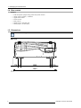
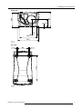

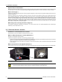
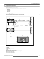
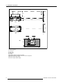
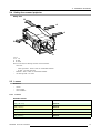
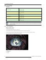
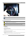
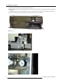
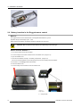
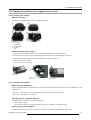
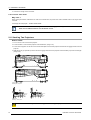
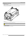

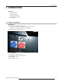
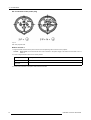
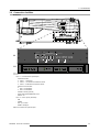

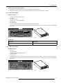
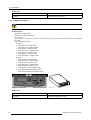
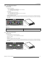
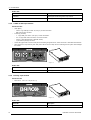
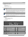
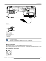
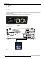

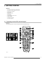
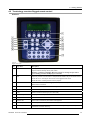
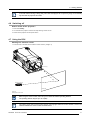
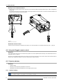
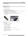


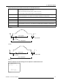
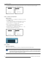
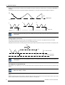
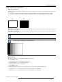
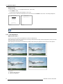
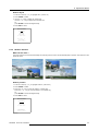
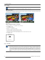
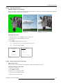
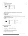
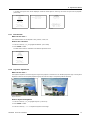
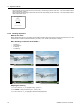
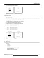
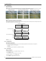
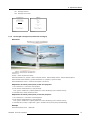
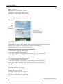
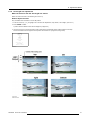

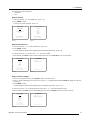
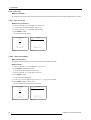
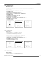
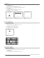
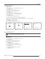
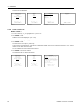
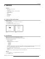
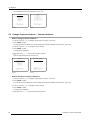
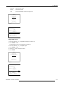
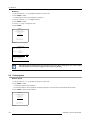
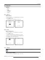
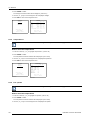
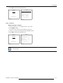

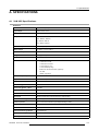
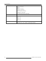
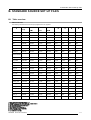
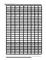
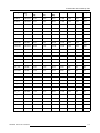


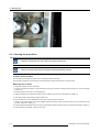
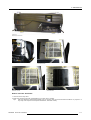


![SLM R12+ Performer [v05]](http://vs1.manualzilla.com/store/data/006296879_1-50504fc86d9979ae79ec928acfe3e08c-150x150.png)


![FLM HD18 [v08]](http://vs1.manualzilla.com/store/data/005664321_1-9e0d84f2b9cac33a4ebfb5904f0dafa1-150x150.png)