1
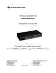
OPERATING MANUAL ES1008 Family of Enclosed Switches 8-Ports 10/100Mbps Switching With Optional 9th Port in 100Mbps Fiber or 10/100Mbps Copper CORPORATE HEADQUARTERS 13705 26th Avenue N., Suite 102 Minneapolis, MN 55441 Phone: (800) 441-5319 Fax: (763) 509-7450 E-mail: [email protected] www.watersnet.com MANUFACTURING/CUSTOMER SERVICE 2411 Seventh Street NW Rochester, MN 55901 Phone (800) 328-2275 Fax: (507) 252-3734 E-mail: [email protected] Table of Contents 1.0 Specifications .............................................................................................................................................. 3 1.1 Technical Specifications................................................................................................................................ 3 2.0 Product Description .................................................................................................................................... 4 2.1 Fiber Ports..................................................................................................................................................... 4 2.2 10/100 Dual-speed Switched Ports, RJ45..................................................................................................... 5 2.3 Frame Buffering and Latency ........................................................................................................................ 5 3.0 Location of the ES1008 Switches .............................................................................................................. 6 3.1 Connecting Ethernet Media. .......................................................................................................................... 6 3.2 Connecting Twisted Pair................................................................................................................................ 6 3.3 Powering the ES1008 Switch. ....................................................................................................................... 7 4.0 Switching Functionality .............................................................................................................................. 7 4.1 Status LEDs .................................................................................................................................................. 7 4.2 Manual Switches for Uplink Button, for RJ45 Port #1 Only ........................................................................... 8 4.3 Manual Switches “F-H”, for Port #9 Only ....................................................................................................... 8 4.4 Auto-negotiation, for Fast Ethernet Copper Ports ......................................................................................... 8 4.5 Auto-negotiation for 10Mbps Ports, Half or Full-Duplex Mode ...................................................................... 8 5.0 Troubleshooting .......................................................................................................................................... 9 5.1 Before Calling for Assistance ........................................................................................................................ 9 ES MODEL# DESCRIPTION ES1008 8-ports switched 10/100Mbps RJ45 ES1008-RJ45 9-ports switched 10/100Mbps RJ45 ES1008-MSC 8-ports switched 10/100Mbps RJ45; plus 1-port 100Mbps multimode fiber (SC) ES1008-MST 8-ports switched 10/100Mbps RJ45; plus 1-port 100Mbps multimode fiber (ST) ES1008-MTRJ 8-ports switched 10/100Mbps RJ45; plus 1-port 100Mbps multimode fiber (MTRJ) ES1008-VF45 8-ports switched 10/100Mbps RJ45; plus 1-port 100Mbps multimode fiber (VF45) ES1008-SSC 8-ports switched 10/100Mbps RJ45; plus 1-port 100Mbps 20 km singlemode fiber (SC) ES1008-SSCL 8-ports switched 10/100Mbps RJ45; plus 1-port 100Mbps 40 km singlemode fiber (SC) ES1008 Operating Manual Page 1 SPECIFICATIONS 1.1 Technical Specifications Performance Aggregate Filtering Rate: (all ports are wire speed) 1,190,400 frames per second for 8 100Mbps ports for ES1008 Aggregate Forwarding Rate: (all ports are wire speed) 595,200 frames per second for ES1008 Fast Ethernet ports Data Rate: 10 Mbps and 100Mbps Address Table Capacity: 16K node addresses, self-learning with address aging Packet Buffer Size: 1 Mbps dynamic Latency: 5 µs + packet time (100 to 100Mbps) 15 µs + packet time (10 to 10 Mbps, and 10 to 100Mbps) Network Standards Ethernet V1.0/V2.0 IEEE 802.3: 10BASE-T, IEEE 802.3u: 100BASE-TX, 100BASE-FX Maximum 10 Mbps Ethernet Segment Lengths Unshielded twisted pair 100 m (328 ft) Shielded twisted pair 150 m (492 ft) 10BASE-FL multimode fiber optic 2 km (6,562 ft) 10BASE-FL singlemode fiber optic 10 km (32,810 ft) Maximum Standard Fast Ethernet Segment Lengths: 10BASE-T (Category (CAT) 3, 4, 5 UTP) 100 m (328 ft) 100BASE-TX (CAT5 UTP) 100 m (328 ft) Shielded twisted pair 150 m (492 ft) 100BASE-FX, half-duplex, multimode 412 m (1,350 ft) 100BASE-FX, full-duplex, multimode 2 km (6,562 ft) 100BASE-SX, short wavelength HDX multimode 300 m (935 ft) 100BASE-FX, half-duplex, singlemode 412 m (1350 ft) 100BASE-FX, full-duplex, singlemode 20 km (49,215 ft) 100BASE-FX, full-duplex, singlemode (long reach) 40 km (132,215 ft) Connectors for Copper Wiring Twisted Pair at 10/100Mbps: RJ45 shielded, female, front mounted (for Waters’ ES1008 Ethernet copper ports, use CAT5 cable) Fiber Multimode Connectors: Fiber Port, SC (snap-in): Fiber multimode, 100BASE-FX Fiber Port, ST (twist-lock): Fiber multimode, 100BASE-FX Fiber Port, MTRJ (plug-in): Fiber multimode, 100BASE-FX Fiber Port, VF45 (plug-in): Fiber Multimode, 100BASE-FX Fiber Singlemode Connectors: Fiber Port, SC: Fiber singlemode, 100BASE-FX Manual Switch-Selections and Jumpers Uplink button: Crossover switch for one RJ45 port#1 th F-H: Optional 9 port (fiber or copper) F for full 100Mbps and H at half-duplex Fiber default: Full-duplex (internal jumpers may select HDX mode) Copper default: Auto-negotiation ES1008 Operating Manual Page 2 LEDs: Per Port LK/Act: Steady ON for Link with no traffic, blinking indicates port is transmitting and receiving F/H: ON = Full-Duplex Mode; OFF = Half-Duplex Mode 100/10: ON = 100Mbps speed; OFF = 10Mbps Operating Environment Ambient Temperature: 32° to 105° F (0° to 50°C) Storage Temperature: -5° to 160°F (-20°to 60°C) Ambient Relative Humidity: 10% to 95% (non-condensing) Power Supply (Internal) AC Power Connector: IEC-type, male recessed at rear of chassis, with adjacent manual ON-OFF switch (on AC models only) Input Voltage: 110 to 240 VAC (auto-ranging) Input Frequency: 47 to 63 Hz (auto-ranging) Power Consumption: 15 watts typical, 20 watts max. Power Supply Rating: 3 Amps at 5 VDC Agency Approvals UL listed (UL1950), cUL, CE Emissions meet FCC Part 15 Class A Warranty Limited lifetime. Contact: Waters Network Systems’ Customer Service at 800-328-2275. Made in USA 2.0 PRODUCT DESCRIPTION - ES1008 Switches Waters’ family of ES1008 switches boosts the performance of Ethernet LANs with the flexibility of both th twisted-pair switched ports and a fiber port. The optional 9 port can be either fiber or copper, and the 8 RJ45 ports are 10/100Mbps and support auto-negotiating. The ES1008 switches provide the switching speed and the reliability to smoothly support multiple workgroups at 10 or 100Mbps. The optional “future-proof” fiber port is 100Mbps with factory default setting to operate in fullduplex mode. Designed for use in workgroups, classrooms, remote offices and network traffic centers, the ES1008 switches are easy to install and use. Addresses of attached nodes are automatically learned and maintained, adapting the switching services to network changes and expansions. Front-mounted LEDs provide status information for each port. All LED connectors and manual switches are located on the front panel of the ES1008 switches. There are power (PWR) and error (Error) indicators for the unit; for visual indication of the operating status of each domain, there are Link and Activity (Link/Act) indicators for each 10Mbps and 100Mbps domain; and there are Speed and F/H Full and Half duplex LEDs for each port. The manual switch with (= x) supports the crossover feature for port #1, th whereas the “F-H” manual switch for the 9 port is user-selectable for full-fixed and half-duplex. 2.1 Fiber Ports th An optional 9 port is available for the ES1008 switch. All optional fiber ports are fixed at 100Mbps for both multi- and singlemode fiber. Multimode fiber ports are available with ST, SC, and MTRJ and VF45 connectors, and singlemode ports are available with SC connectors. The 100Mbps fiber port modules on the ES1008 are factory set to operate in full-duplex mode for best fiber distance and performance. On the ES1008 fiber models there are two LED’s per fiber port. The Link (LK) LED indicates, “ready for operation” when lit, and an LED indicates Receiving Activity (ACT) on the port. A fiber cable must be connected to ES1008 Operating Manual Page 3 each 100Mbps port and a proper link (LK lit) must be made with the device at the other end of the cable in order for the LK LEDs to provide valid indications of operating conditions. 2.2 10/100 Dual-speed Switched Ports, RJ45 (Copper) All ES1008 models have 8 10/100Mbps dual speed switch ports. The 10/100Mbps switched ports are independently N-way auto-negotiating (as a default setting), for operation at 10 or POWER SPEED ERROR L/A UPLINK F/H = 1 2 3 4 5 6 7 8 X 100Mbps in full- or half-duplex mode. They independently move to half-duplex mode at 10 Mbps or at 100Mbps speed if the device at the other end of the twisted pair cable is halfduplex or is not an auto-negotiating device. There are three LED’s for each port. The LK/Act (Link/Activity) steady ON for Link with no traffic and blinking indicates port is receiving and transmitting. The Speed LED indicates operation at 100Mbps speed when ON and at 10 Mbps speed when OFF (when auto-negotiation is not disabled). The F/H LED is ON to indicate full-duplex operation and OFF to indicate half-duplex mode. A twisted pair cable must be connected into each RJ45 10/100Mbps port and a proper Link (LK lit) must be made with the device at the other end of the cable in order for the LEDs to provide valid indications of operating conditions. Port #1 is equipped with a Media Dependent Interface-Crossover (MDI-X) push-button switch to simplify cascaded or uplink connections. 2.3 Frame Buffering and Latency All ES1008 models are store-and-forward switches. Each frame (or packet) is loaded into the switch’s memory and inspected before forwarding can occur. This technique ensures that all forwarded frames are a valid length and have the correct CRC, i.e. good packets. This eliminates the propagation of bad packets, enabling all of the available bandwidth to be used for valid information. While other switching technologies such as "cut-through" or "express" impose minimal frame latency, they will also permit bad frames to propagate out to the connected Ethernet segments. The "cut-through" technique permits collision fragment frames, which are a result of late collisions, to be forwarded to add to the network traffic. Since there is no way to filter frames with a bad CRC (the entire frame must be present in order for CRC to be calculated), the result of indiscriminate cut-through forwarding is greater traffic congestion, especially at peak activity. Since collisions and bad packets are more likely when traffic is heavy, the result of store-and-forward operation allows more bandwidth to be available for good packets when the traffic load is greatest. To minimize the possibility of dropping frames on congested ports, each ES1008 switch dynamically allocates buffer space from a 1Mbps memory pool, ensuring that heavily used ports receive very large buffer space for packet storage. Many other switches have their packet buffer storage space divided evenly across all ports, resulting in a small, fixed number of packets to be stored per port. When the port buffer fills up, dropped packets result. This dynamic buffer allocation provides the capability for the maximum resources of the ES1008 switch to be applied to all traffic loads, even when the traffic activity is unbalanced across the ports. Since the traffic on an operating network is constantly varying in packet density per port and in aggregate density, the ES1008 switches are constantly adapting internally to provide maximum network performance with the least dropped packets. When the ES1008 switch detects that its free buffer queue space is low, the switch sends industry standard (full-duplex only) PAUSE packets out to the devices sending packets to cause “flow control”. This tells the sending devices to temporarily stop sending traffic, which allows a traffic catch up to occur without dropping packets. Then, normal packet buffering and processing resumes. This flow-control sequence occurs in a fraction of a second and is transparent to an observer. Another feature implemented in ES1008 switches is a collision-based flow-control mechanism (when operating at half-duplex only). When the switch detects that its free buffer queue space is low, the switch prevents ES1008 Operating Manual Page 4 more frames from entering by forcing a collision signal on all receiving half-duplex ports in order to stop incoming traffic. The latency (the time the frame spends in the switch before it is sent along or forwarded to its destination) of the ES1008 switches varies with the port-speed types, and the length of the frame is a variable here as it is with all store-and-forward switches. For 10Mbps-to-10Mbps or 10Mbps-to-100Mbps or 100Mbps-to-10Mbps forwarding, the latency is 15 microseconds plus the packet time at 10Mbps. For 100Mbps-to-100Mbps forwarding, the latency is 5 microseconds plus the packet time at 100Mbps. 3.0 LOCATION OF THE ES1008 SWITCHES The location of a Waters’ ES1008 switch is dependent on the physical layout of the network. The switch can be placed in a central wiring location or preferably a workgroup area where groups of network devices need to be connected in order to communicate with each other. With Waters’ rugged enclosed housing, the switches are typically wall mounted, or, with the rubber feet, they can also be installed on a shelf or tabletop. The rugged housing of the ES1008-switch protects the electronics from environmental conditions and limits any tampering of the connections. For power, locate an AC receptacle that is within six feet (2 meters) of the location of the switch. Maintain an open view of the front to visually monitor the status LEDs. Keep an open area around the unit so that cooling can occur while the unit is in operation. 3.1 Connecting Ethernet Media The ES1008 Switches are specifically designed to support all standard Ethernet media types within a single switch unit. The various media types supported along with the corresponding IEEE 802.3 and 802.3u standards and connector types are as follows: IEEE Standard Media Type Max. Distance Port Module mm1 fiber 2 km (6,562 ft) ES1008-MSC, MST Fiber: 100BASE-FX sm2 fiber small form factor mm1 fiber 18 km (95,000 ft) ES1008-SSC 2 km (6,562 ft) ES1008-MTRJ, VF45 100m (328 ft) RJ45 Copper: 10BASE-T & 100BASE-TX 1 mm = multimode 3.2 twisted pair 2 sm = singlemode Connecting Twisted Pair (RJ45, CAT3, CAT5, Unshielded or Shielded) The RJ45 ports of Waters’ ES1008 switch can be connected to the following two media types: 100BASE-TX and 10BASE-T. Category (CAT) 5 cables should be used when making 100BASE-TX connections. When the ports are used as 10BASE-T ports, CAT3 may be used (although the use of CAT3 cabling is not recommended). In either case, the maximum distance for unshielded twisted pair cabling is 100 meters (328 ft). Media Twisted Pair (CAT3, 4, 5) Twisted Pair (CAT5) IEEE Standard Connector 10BASE-T RJ45 100BASE-TX RJ45 Note : It is recommended that high quality CAT5 cables (which work for both 10Mbps and 100Mbps) be used whenever possible in order to provide flexibility in a mixed-speed network, since dual-speed ports are auto-sensing for either 10 and 100Mbps. ES1008 Operating Manual Page 5 The following procedure describes how to connect a 10BASE-T or 100BASE-TX twisted pair segment to the ES1008 RJ45 port. The procedure is the same for both unshielded and shielded twisted pair cables. 1. Using standard twisted pair media, insert either end of the cable with an RJ45 plug into the RJ45 connector of the port. Note that, even though the connector is shielded, either unshielded or shielded cables and wiring may be used. 2. Connect the other end of the cable to the corresponding device. 3. Use the LINK LED to ensure proper connectivity by noting that the LED will be illuminated when the unit is powered and proper connection is established. 3.3 Powering the ES1008 Switch Waters’ ES1008 switches incorporate an internal universal power supply using a recessed male IEC connector for the AC power cord. A six-foot 115 VAC 60 Hz standard power cord is supplied with each unit shipped within the United States and Canada. 4.0 SWITCHING FUNCTIONALITY Waters’ ES1008 family of switches provides switched connectivity at Ethernet wire speed among all of its ports. The ES1008-switch supports10/100Mbps for copper media and 10 or 100Mbps separate traffic domain for fiber port to maximize bandwidth utilization and network performance. All ports communicate to all other ports in a Waters’ ES1008, but local traffic on a port will not consume any of the bandwidth on any other port. Waters’ ES1008 switches are plug-and-play devices. There is no software configuration required at installation or for maintenance. The only hardware configuration settings are user options for uplink on the RJ45 port and Half / Full duplex mode. Filtering and Forwarding Each time a packet arrives on one of the switched ports, the decision is taken to either filter or to forward the packet. Packets whose source and destination addresses are on the same port segment will be filtered, constraining them to that one port and relieving the rest of the network from processing them. A packet whose destination address is on another port segment will be forwarded to the appropriate port and will not be sent to the other ports where it is not needed. Traffic needed for maintaining the operation of the network (such as occasional multi-cast packets) is forwarded to all ports. Waters’ ES1008 switches operate in store-and-forward switching mode, which eliminates bad packets and enables peak performance to be achieved when there is heavy traffic on the network. Address Learning All Waters’ ES1008 switches have an address table capacity of 16K node addresses suitable for use in large networks. They are self-learning, so that as nodes are added, removed or moved from one segment to another, the ES1008 switch automatically maintains the proper node locations. An address-aging algorithm causes least-used addresses to fall out in favor of new, frequently used addresses. To reset the address buffer, cycle power down-and-up. 4.1 Status LEDs For ES1008 models: PWR Power LED, ON when external power is applied to the unit. ERROR Self-test at power up failed LK/Act Steady ON for link with no traffic, blinking indicates port is transmitting and receiving. F/H Full / Half duplex LED, ON when the port is running full duplex, OFF for half duplex. Speed Speed LED, ON when the speed is 100Mbps , OFF when the speed is 10Mbps ES1008 Operating Manual Page 6 4.2 Manual Switches for Uplink Button, for RJ45 Port #1 Only The ES1008 switch has a manual uplink sliding switch, located on the front panel next to 10/100Mbps RJ45 port #1 which it controls. It enables the port’s cable to either connect to a user station node (push in) or to be cascaded (push out) to a 10/100Mbps repeater or switching hub in the network. Verify proper uplink button position by noting Port 1’s LK (link) LED status, which is illuminated when a proper link is made. 4.3 Manual Switches “F-H”, for Port #9 Only The ES1008 Switch has a manual sliding switch labeled “F-H” located on the front panel next to port #9. This manual switch controls the full (F) and half (H) duplex for port #9. When port #9 is on “F”, the port is set to full duplex at 100Mbps. When port #9 is on “H”, the port is set to half duplex. 4.4 Auto-negotiation, for Fast Ethernet Copper Ports Waters’ ES1008 copper ports are factory set at 10/100 F/H N-way auto-negotiation per the IEEE802.3u standard. When the RJ45 ports are set for auto-negotiation and connected to another auto-negotiating device, there are four modes available depending on the mode the other device supports. These are: (1) 100Mbps full-duplex, (2) 100Mbps half-duplex, (3) 10Mbps full-duplex and (4) 10Mbps half-duplex. The auto-negotiation logic will attempt to operate in descending order and will normally arrive at the highest order mode that both devices can support at that time. (Since auto-negotiation is potentially an externally controlled process, the original “highest order mode” result can change at any time depending on network changes that may occur). If the device at the other end is not an auto-negotiating device, the ES1008 switch’s RJ45 ports will try to detect its idle signal to determine 10 or 100Mbps speed and will default to half-duplex at that speed per the IEEE standard. General information Auto-negotiation per-port for 802.3u-compliant switches occurs when: The devices at both ends of the cable are capable of operation at either 10Mbps or 100Mbps speed and/or in full- or half-duplex mode and can send/receive auto-negotiation pulses, and When the second of the two connected devices is powered up*, i.e., when LINK is established for a port, or When LINK is re-established on a port after being lost temporarily. NOTE: Some NIC cards only auto-negotiate when the computer system that they are in is powered up. These are exceptions to the “negotiate at LINK – enabled” rule above, but may be occasionally encountered. When operating in 100Mbps half-duplex mode, cable distances and hop-counts may be limited within that collision domain. The Path Delay Value (PDV) bit-times must account for all devices and cable lengths within that domain. The bit time delay is 50BT for Waters’ ES1008 switch ports operating at 100Mbps half-duplex. 4.5 Auto-negotiation for 10Mbps Ports, Half- or Full-Duplex Mode Full-duplex Ethernet provides separate Transmit and Receive data paths, enabling simultaneous bi-directional collision-free data movements on a port. The network topology must be a “star” type, not a “bus” type. With fullduplex mode, the cable distance is only limited by the physical layer line driver and cable attenuation. There are no collision-domain restrictions or limitations. Waters’ ES1008 switches perform half- or full-duplex mode auto-negotiation independently on all switched ports. If the device or node on the other end of a port’s attached cable supports F/H mode auto-negotiation or is set to operate as full-duplex, the ES1008 switch will negotiate to run full-duplex. If the attached device or node doesn’t support F/H mode auto-negotiation (for example, if it is a 10Mbps repeater or a standard 10Mbps hub), the switch’s RJ45 ports will default to operate at half-duplex. ES1008 Operating Manual Page 7 5.0 TROUBLESHOOTING All Waters’ Ethernet products are designed to provide reliability and consistently high performance in all network environments. The installation of Waters’ ES1008 switches is a straightforward procedure (see Section 3); the operation is also straightforward and is discussed in Section 4. Should problems develop during installation or operation, this section is intended to help locate, identify and correct these types of problems. Please follow the suggestions listed below prior to contacting your supplier. However, if you are unsure of the procedures described in this section or if Waters’ ES1008 family of switches is not performing as expected, do not attempt to repair the unit; instead contact your supplier for assistance or contact Waters Network Systems’ Customer Service at 800-328-2275. 5.1 1. Before Calling for Assistance If difficulty is encountered when installing or operating the unit, refer to the Installation Section of the applicable chapter of this manual. Also check to make sure that the various components of the network are interoperable. 2. Check the cables and connectors to ensure that they have been properly connected and the cables/wires have not been crimped or in some way impaired during installation. (About 90% of network downtime can be attributed to wiring and connector problems.) 3. Make sure that an AC power cord is properly attached to each Waters’ ES1008 switch. Be certain that each AC power cord is plugged into a functioning electrical outlet. Use the PWR LEDs to verify each unit is receiving power. 4. If the problem is isolated to a network device other than Waters’ ES1008 switch, it is recommended that the problem device be replaced with a known good device. Verify whether or not the problem is corrected. If not, go to Step 5 below. If the problem is corrected, Waters’ ES1008 switch and its associated cables are functioning properly. 5. If the problem continues after completing Step 4 above, contact Waters Network Systems Customer Service at 800-328-2275 or email [email protected] for assistance. 2001 Waters Network Systems. All rights reserved. The information contained in this document is subject to change without prior notice. All trademarks are the property of their respective owners. ES1008 Operating Manual WNS part number 7000346.001 Page 8