1
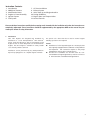
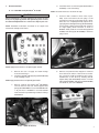
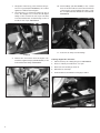
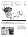
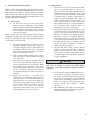
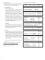
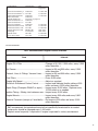
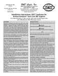
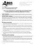
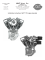
®
Instruction 106-4500
10-29-08
S&S Cycle, Inc.
14025 Cty Hwy G
Viola, Wisconsin 54664
Copyright® 2008
Phone: 608-627-1497 • Fax: 608-627-1488
by S&S Cycle, Inc.
Technical Service Phone: 608-627-TECH (8324)
Technical Service Email: [email protected]
Website: www.sscycle.com
All rights reserved.
Printed in the U.S.A.
Installation Instructions: S&S® T111 Engine Assembly
DISCLAIMER:
IMPORTANT NOTICE:
S&S parts are designed for high performance, closed course racing
applications and are intended for the very experienced rider only. The
installation of S&S parts may void or adversely effect your factory
warranty. In addition such installation and use may violate certain
federal, state, and local laws, rules and ordinances as well as other laws
when used on motor vehicles used on public highways, especially in
states where pollution laws may apply. Always check federal, state, and
local laws before modifying your motorcycle. It is the sole and exclusive
responsibility of the user to determine the suitability of the product for
his or her use, and the user shall assume all legal, personal injury risk and
liability and all other obligations, duties, and risks associated therewith.
Statements in this instruction sheet preceded by the following words
are of special significance.
The words Harley®, Harley-Davidson®, H-D®, Sportster®, Evolution®, and
all H-D part numbers and model designations are used in reference only.
S&S Cycle is not associated with Harley-Davidson, Inc.
S&S recommends you take special notice of these items.
SAFE INSTALLATION AND OPERATION RULES:
Before installing your new S&S part it is your responsibility to read and
follow the installation and maintenance procedures in these
instructions and follow the basic rules below for your personal safety.
Gasoline is extremely flammable and explosive under certain
conditions and toxic when inhaled. Do not smoke. Perform installation
in a well ventilated area away from open flames or sparks.
If motorcycle has been running, wait until engine and exhaust pipes
have cooled down to avoid getting burned before performing any
installation steps.
Before performing any installation steps disconnect battery to
eliminate potential sparks and inadvertent engagement of starter while
working on electrical components.
Read instructions thoroughly and carefully so all procedures are
completely understood before performing any installation steps.
Contact S&S with any questions you may have if any steps are unclear
or any abnormalities occur during installation or operation of
motorcycle with a S&S part on it.
Consult an appropriate service manual for your motorcycle for correct
disassembly and reassembly procedures for any parts that need to be
removed to facilitate installation.
Use good judgment when performing installation and operating
motorcycle. Good judgment begins with a clear head. Don't let
alcohol, drugs or fatigue impair your judgment. Start installation when
you are fresh.
Be sure all federal, state and local laws are obeyed with the
installation.
For optimum performance and safety and to minimize potential
damage to carb or other components, use all mounting hardware that
is provided and follow all installation instructions.
Motorcycle exhaust fumes are toxic and poisonous and must not
be inhaled. Run motorcycle in a well ventilated area where fumes
can dissipate.
2
WARNING
Means there is the possibility of injury to yourself or others.
CAUTION
Means there is the possibility of damage to the part or motorcycle.
NOTE
Other information of particular importance has been placed in italic type.
WARRANTY:
All S&S parts are guaranteed to the original purchaser to be free of
manufacturing defects in materials and workmanship for a period of
twelve (12) months from the date of purchase. Merchandise that fails
to conform to these conditions will be repaired or replaced at S&S’s
option if the parts are returned to us by the purchaser within the 12
month warranty period or within 10 days thereafter.
In the event warranty service is required, the original purchaser must
call or write S&S immediately with the problem. Some problems can be
rectified by a telephone call and need no further course of action.
A part that is suspect of being defective must not be replaced by a
Dealer without prior authorization from S&S. If it is deemed necessary
for S&S to make an evaluation to determine whether the part was
defective, a return authorization number must be obtained from S&S.
The parts must be packaged properly so as to not cause further damage
and be returned prepaid to S&S with a copy of the original invoice of
purchase and a detailed letter outlining the nature of the problem, how
the part was used and the circumstances at the time of failure. If after
an evaluation has been made by S&S and the part was found to be
defective, repair, replacement or refund will be granted.
ADDITIONAL WARRANTY PROVISIONS:
(1) S&S shall have no obligation in the event an S&S part is modified by
any other person or organization.
(2) S&S shall have no obligation if an S&S part becomes defective in
whole or in part as a result of improper installation, improper
maintenance, improper use, abnormal operation, or any other misuse
or mistreatment of the S&S part.
(3) S&S shall not be liable for any consequential or incidental damages
resulting from the failure of an S&S part, the breach of any warranties,
the failure to deliver, delay in delivery, delivery in non-conforming
condition, or for any other breach of contract or duty between S&S and
a customer.
(4) S&S parts are designed exclusively for use in Harley-Davidson® and
other American v-twin motorcycles. S&S shall have no warranty or
liability obligation if an S&S part is used in any other application.
Instruction Contents:
123456-
Introduction
Additional Features
Modification Notes
Engine to Frame Assembly
Ignition System
Fuel System
789101112-
Oil Line Installation
Exhaust System
Initial Start-up and Engine Break-In
Tuning Guidelines
Engine Specs and Torque Values
Service Intervals
Please read these instructions carefully before starting work. Proceed with the installation only after the instructions are
completely understood. These instructions should be supplemented by the appropriate OEM service manual for your
motorcycle. Follow all safety information.
1-
Introduction
S&S® T111 Engines are designed and intended for
installation in a stock Harley-Davidson® Twin Cam 88®
chassis. It will bolt directly to the stock transmission and
engine mounts of chassis designed for stock Twin Cam 88®
engines. The T111 Engine is available in silver powder
coat or black powdercoat finish.
Installation can be performed by any Harley-Davidson®
repair shop equipped to do complete engine overhauls.
No special tools other than those used in normal engine
building operations are required.
NOTES
Installation of a fuel injected engine in a motorcycle that
was originally equipped with a carburetor is fairly difficult
and expensive. This conversion requires a fuel pump
equipped gas tank as well as wiring harness.
All S&S T111 assemblies are for Twin Cam 88® noncounterbalanced engine applications, and are not for use
in Twin Cam 88B® counterbalanced applications.
3
Torque
Horsepower
Dynomometer chart showing typical horsepower and torque curves for S&S 111” T111 engine.
Horsepower and torque curves will vary, dependent on the engines state of tune, and the ignition and fuel systems
used on the completed engine.
2
Additional Features:
Greater overall strength than stock crankcases, especially
in the front motor mount, an important consideration in
high performance applications.
All oil passages between the crankcase and cam support
plate are O-ring sealed.
Compatible with stock components. Use stock oil pump,
cam support plate, gear cover, etc.
Uses 1999-2002 Timken® style sprocket shaft bearing.
Uses 2003-up pinion shaft bearing
S&S® T111 instructions often refer to procedures
described in other S&S instructions or a Harley-Davidson®
Service Manual. These materials should be crossreferenced as necessary.
4
IMPORTANT
Before proceeding, verify that serial numbers on crankcases
match numbers on packing carton and certificate of origin.
Contact S&S immediately if numbers do not match.
NOTE - Valid certificate of origin is required for any transfer
or sale of longblock assemblies. Certificate of origin is
required to title and license any motorcycle which is to be
driven on public streets and highways.
3-
Modification Notes
S&S® Cycle cautions against modifying these crankcases
due to the possibility of damaging or weakening them.
Modifying S&S crankcases in any fashion voids all
manufacturer warranties. Should the customer elect to
modify the crankcases regardless, it is imperative that
they and the information tag attached to them be
inspected beforehand to confirm that the correct model,
style, bore size, etc. have been provided. The customer
must confirm that crankcases and related parts are correct
before assembling them or having them modified in any
manner, and assumes all liability for modifications.
Under no circumstance will S&S be held responsible for
expenses related to the modification of any S&S part in
the event warranty service is required. Modified parts will
not be accepted for credit or exchange. This will apply
regardless of cause or fault: customer, retailer,
manufacturer, or other.
For further information, contact S&S Technical Services at
608-627-8324,
FAX
608-627-1488
or
e-mail
[email protected]
NOTE - Modification includes but is not limited to appearance
changes such as painting, powdercoating, plating, and
polishing. Proper preparation for these procedures as well as
the processes themselves may require the use of polishing
compounds, chemicals or procedures that are potentially
harmful to crankcases.
CAUTION
Passages and internal cavities may become obstructed by
residues from materials used to polish, paint, plate or
powdercoat surfaces. Additionally, surface finishing
processes can damage critical machined surfaces. Any of
the above may cause premature wear, damage or failure
of other engine components as well as the crankcases
themselves.
Glass bead and polishing residues are abrasive and can be
difficult to remove from recesses and small passages.
Abrasive residues can cause oil contamination and
extensive engine damage. Engine damage caused by
powder coating, polishing, glass bead blasting, or other
modification will not be covered under warranty.
4-
Engine To Frame Assembly
The engine should be installed into the frame before
the ignition, fuel, exhaust, and oil system components
are installed.
Follow the engine to frame fitting below:
Engine to Frame Test Fit
NOTE - The engine must be fitted to the frame it is installed
into. It must rest squarely on its attachment points, and bolted
solidly to the frame without stressing the engine case at any
point.
CAUTION
Failure to correctly mount the engine can cause problems not
covered under warranty including but not limited to,
excessive vibration, driveline mis-alignment, and broken
castings.
A- Test-fit instructions for T111 style cases with stock
1999-up engine mounts.
1-
Clean frame engine mounts and carefully remove
any irregularities from mounting surfaces. Also
inspect crankcase mounting bosses for burrs.
2-
Position engine in frame, check for clearance at
frame, and alignment to transmission. It is a
good idea to replace rubber engine mounts at
this time. Old mounts deform over time and can
induce unwanted stresses on the engine case.
Replace all other motorcycle components removed for
engine installation. Consult authorized Harley-Davidson®
service manual for installation procedure for stock parts
not covered in S&S instructions.
NOTE- On certain models it may be necessary to switch the
shift linkage to the outside of the shift lever. Make certain
that there is clearance between the shifter rod and the engine
crankcases.
Powder Coating - Subjecting heat-treated alloys such as
those used in S&S crankcases to excessive heat can
drastically alter their strength and their critical properties.
The degree of change depends upon the temperatures
reached and the duration of exposure. When powder
coating or otherwise processing alloy parts, S&S exposes
them to a maximum temperature of 370°F for no longer
than 20 minutes. Under no circumstances should parts be
heated past 400°F!
S&S strongly recommends trial-fitting every engine
before frame is painted or powdercoated.
5
5-
Ignition System Installation
6-
A- All Carbureted S&S T111 assemblies come with an S&S
IST (Intelligent Spark Technology) ignition. Use of this
ignition system is highly recommended. All aspects of
ignition timing- advance, retard, and curves are
handled automatically by the S&S IST ignition.
NOTES - S&S® Engine assemblies are available with either
carbureted or fuel injected systems.
B-
Once the IST ignition has been installed per the
included instruction sheet 51-1155, no other
adjustments are necessary
Fuel system installation and tuning
Assembled Engines are shipped with the carburetor or fuel
injection system installed. Refer to the included instructions for
operation and tuning .
A- Install fuel system.
NOTES
If the S&S IST ignition is not used, S&S recommends using
electronic ignition with adjustable advance curve in S&S
T111 engines. Adjustable curve permits slowing rate of
advance to control or eliminate pinging under heavy load
or when elevated temperatures or poor quality gasoline
encountered.
All other ignition systems other than the included S&S IST
ignition install per manufacturers instructions.S&S
recommends setting the total ignition advance to 28
degrees. Timing degree recommendations given by S&S
take precedence over the ignition manufacturers
instructions.
B-
1-
Engine assemblies supplied with Super “E”
carburetors, refer to included instruction sheet
51-1012.
2-
Engine assemblies supplied with fuel injection, refer
to included Induction System instruction Sheet.
Re-install and connect fuel tank.
1-
Refer to appropriate service manual. Inspect fuel
lines and clamps - replace as necessary.
2-
Check fuel line connections and routing. Avoid
hot surfaces. Make certain that the protective
cover has been placed over fuel line, and that it
is clear from sharp edges and abrasive surfaces.
3-
Fill the fuel tank with a sufficient quantity of
gasoline for the initial start-up procedure.
4-
Double check that all fuel line connections have
been made correctly and there is no gas leakage
at any point in the system.
CAUTION
Timing
engine
engine
applies
that is too advanced will result in detonation and
damage. Timing that is too retarded will result in
over-heating and engine damage. (This caution
only to installations other than the S&S IST Ignition)
CAUTION
If S&S determines that engine damage was caused by
improper ignition timing, repair will not be covered under
warranty.
Excessive ignition advance will cause engine to kick back
against the starter during start-up and “buck” when ridden at
steady speed with partial throttle. An advanced condition can
also cause pinging or ignition knock and possible piston
damage. These symptoms may not be noticed if electronic
ignition with “soft” advance curve is used.
Excessive ignition retard causes sluggish performance and
severe overheating with possible subsequent damage to the
engine, and must also be avoided. Immediate or rapid exhaust
pipe discoloration is usually a sign of retarded ignition timing.
6
7-
Oil Line Installation
4-
Install the vent hose and clamp (S&S PN 50-8156 or
50-8076-S) on the new fitting.
A- For 1999-2006 Harley-Davidson® FL models
NOTE- The stock vent hose is reused in this step.
CAUTION
5-
Oil line installation is crucial to engine life. If you are not sure
that you can properly perform this operation, please contact
the S&S Tech Department for a referral to a shop in your area.
NOTE- Installation instructions are based on an engine and
transmission already in the chassis.
Position a drain container in front of the oil pan.
Next, locate and remove the two plugs on the
forward face of the oil pan allowing the oil to drain.
Once the oil is completely drained, replace the 3⁄8”
pipe-plug with a 90-degree fitting (S&S PN 50-8288).
Position barb of fitting toward right side of bike at
an angle slightly above horizontal as shown in
Picture 2. Next, install the oil return fitting (S&S PN
50-0451) with O-ring (S&S PN 50-8008) in the drain
plug location.
FL Oil Line Install Kit (PN 31-0425)
NOTE- Apply thread sealant to all tapered pipe threads.
12-
Remove the stock oil supply and return fittings
from the transmission.
Install two supplied 3⁄8 NPT pipe plugs (S&S PN 50-8330)
in the oil fitting location.
NOTE- Apply thread sealant to all tapered pipe threads.
3-
Remove crankcase vent fitting (S&S® PN 50-0451)
and set aside for later use. Install supplied vent
fitting (S&S PN 50-0449 is for use with 2002-’06 with
7
⁄16 ID vent hose or 50-0454 for use with 1999-’01
with 3⁄8 ID vent hose) with O-ring installed on fitting.
See Picture 1.
Picture 2
6-
Remove cover plate that was shipped on crankcase
from the bottom surface of the rear motor mount.
The oil line block will be installed in this location.
Assemble the oil line block by installing the 90degree fitting (S&S PN 50-8288) and the oil return
fitting (S&S PN 50-0451) with O-ring (S&S PN 50-8008)
into the block, as shown in Picture 3.
Picture 3
Picture 1 (2002-’06 Shown)
7
7-
8-
Mount the oil line block on the crankcase using 5⁄1618 x 13⁄4” long screw (S&S® PN 50-0437)—do not final
tighten as it will be removed again.
The next step is to measure and then cut the oil
hoses. The straight hose connects the 90 degree
fittings of the oil line block and oil pan. The bent
hose runs between the oil return fittings on the oil
line block and oil pan. See Picture 4.
10- Install O-Rings (S&S PN 50-8066) in the counter
bores of the oil line block. Position the oil line block
on the engine case and tighten the screw to 18 ftlbs. of torque with blue threadlock on the threads.
See Picture 6.
Picture 6
11- Position hose clamps over the fittings.
Picture 4
9-
Remove the oil line block from the engine case.
Install the supplied clamps (S&S PN 50-8156) on the
lines between the fittings. See Picture 5.
To Change Engine Oil in the Future
1-
Slide hose clamp off of fitting along hose. See Picture 7.
2-
Place an oil drain pan under front of oil pan.
3-
Remove hose from fitting to drain oil.
4-
Reinstall hose and clamp.
5-
Continue with recommended oil change procedure.
Picture 5
Picture 7
8
S&S® Replacement Parts for Harley-Davidson® FL Models
12345-
Block, Oil line .........................................................106-1168
BHSHCS, 5⁄16-18 x 13⁄4 (10 pack) .................................106-1169
O-ring (10 pack) .........................................................50-8066
Fitting, Pipe, 90 degree (2 pack)...........................106-1170
Fitting,
7
⁄16 (2 pack) ............................................................106-1171
3
⁄8 (2 pack) ............................................................106-1172
B-
For 1999-’05 Harley-Davidson® Dyna® models
CAUTION
Oil line installation is crucial to engine life. If you are not sure
that you can properly perform this operation, please contact
the S&S Tech Department for a referral to a shop in your area.
6789-
Fitting, 1⁄2 (2 pack)....................................................106-1173
O-ring (10 pack) .......................................................106-1183
Hose, oil feed ...........................................................50-8157
Clamp,
Double Wire Spring (10 pack) ..............................50-8156
Hose, Spring (10 pack) ........................................106-1174
10- Hose, Oil Line, 90 degree bend ..............................50-8292
11- Plug, pipe (10 pack).................................................106-1175
12-
NOTE: Apply thread sealant to all tapered pipe threads.
3-
NOTE: Installation instructions are based on an engine and
transmission already in the chassis.
4-
Dyna® Oil Line Istall Kit (PN 31-0424)
Remove the stock oil supply and return fittings from
the transmission.
Install two supplied 3⁄8 NPT pipe plugs (S&S PN 50-8330)
in the oil fitting location.
Drain the oil from the oil pan—see the proper
factory service manual for instructions—and then
remove the oil pan from the motorcycle.
Place the supplied template (53-0080) over the oil
pan baffle and use a scribe to mark the location of
the 1⁄2” hole as shown in Picture 8. Use a drill press to
machine the 1⁄2” hole as marked in Picture 8a. Use a
small file or deburring tool to make sure no chips or
pieces are left on the 1⁄2” hole and then clean the oil
pan and baffle with a solvent before reinstalling
the pan with a new gasket on the motorcycle.
9
8-
9-
Install the transmission top cover screws and
washers according to Detail A. Use blue threadlock
on the screws, but leave them loose at this time. See
Detail A in exploded view of replacement parts for
Harley-Davidson® Dyna® on page 11.
Remove the oil line retention plate, plugs and seals
from the top of the engine crankcase. Remove seals
from the plugs. Discard the plugs.
Picture 8
Picture 10
Picture 8a
5-
6-
7-
Remove the transmission top cover. Remove the
neutral indicator switch, vent line and fitting from
the transmission top cover.
Install the neutral indictor switch, vent line and
fitting on the new S&S transmission top cover (S&S
PN 56-1615).
Slide the oil feed line (S&S PN 31-0449) through the
hole in the top cover closest to the oil filler/dipstick
boss. Place a new top cover gasket (S&S PN 56-1261)
on the transmission case and position the new S&S®
top cover on it. Rotate the oil feed line so it will pass
through the 1⁄2” hole in the baffle. Be sure the bend
in the oil feed line orientation is to the rear of the
motorcycle. See Picture 9.
10- To install the oil lines (S&S PN 31-0447 and 31-0448),
orient the ends and openings so they are parallel.
Insert the lines through the oil line retention plates,
then the included washers (S&S PN 50-0439) and,
last the seals (S&S PN 50-8271) on each line end.
The ends of the lines should protrude through the
seals about 1⁄8 inch.
11- Position oil line assembly on both the transmission
top cover and crankcase and press down until lines
are firmly seated in the counterbores in the
crankcase and transmission cover.
Picture 11
Picture 9
10
12- Press the oil line retention plates into place until
they seat. Install the two screws (5⁄16-18 x 3⁄4 button
head) through the oil line retention plates. First
screw goes in the transmission top cover and the
second mounts into the crankcase near the rear
motor mount. Treat both screws with blue
threadlock and tighten to 18-ft-lbs.
13- Tighten transmission top cover screws to 100-120 in-lbs.
14- Install the vent line (S&S PN 50-8291) with clamps
(S&S PN 50-8156).
15- Reconect neutral switch wires.
16- Check function of neutral switch.
S&S® Replacement Parts for Harley-Davidson® Dyna® Models
12345678910111213-
Plate ........................................................................106-1176
Seal (4 pack) .............................................................106-1177
BHSHCS 5⁄16-18 x 3⁄4 (10 pack) ....................................106-1178
Washer (4 pack) .......................................................106-1185
Line, oil supply .........................................................31-0447
Line, oil return..........................................................31-0048
Line assembly, oil feed.............................................31-0449
Top cover ..................................................................56-1615
SHC - 1⁄4-20 x 11⁄2” (10 pack) ......................................106-1179
SHC - 1⁄4-20 x 21⁄4" (10 pack) ......................................106-1180
SHC - 1⁄4-20 x 13⁄4" (10 pack) ......................................106-1181
SHC - 1⁄4-20 x 11⁄4" (10 pack) ........................................50-0330
Gasket, tranny top cover.........................................56-1261
14151617181920-
Drill Template .........................................................106-1188
Fitting (5 pack) ........................................................106-1182
Hose, 90-degree bend .............................................50-8292
Clamp (10 pack) .........................................................50-8156
Plug, pipe (10 pack).................................................106-1175
O-ring (10 pack) .......................................................106-1183
Fitting (2 pack) ........................................................106-1173
15
17
20
17
6
5 19
3
16
3
1
1
4
2
4
14
8
7
10
13
9
14
18
12
11
11
C-
Oil recommendations
NOTES
S&S® Cycle recommends the use of Mobil 1® V-TWIN 20W50 synthetic oil in our engines.
S&S Cycle recommends the use of S&S® oil filters, PN 31-4103
(black), or PN 31-4104 (chrome).
All reference to Harley-Davidson® part numbers is for
identification purposes only. We in no way are implying that
any of S&S® Cycle’s products are original equipment parts or
that they are equivalent to the corresponding HarleyDavidson® part number shown.
If not using Mobil 1® V-TWIN 20W-50:
Viscosity
Ambient Temperature (º F)
SAE 20W50
Above 20º - 100º
SAE 50
Above 60º - 100º
SAE 60
Above 80º - 100º
NOTES
If oil fails to appear at oil sender hole within 30 seconds
of starter operation, allow the starter to cool. Verify that
oil line routing is correct and that the oil tank is full to the
proper level.
Oil pressure indicator lamp should light when ignition is
turned on. Lamp will go out after engine is started and
there is oil pressure at the switch in the crankcase.
CAUTION
Avoid excessive time of starter engagement. Overheating of
starter motor will result in damage. Oil pump should prime
and deliver oil to the oil sender hole within 30 seconds.
8-
Exhaust System
NOTE - The engine must be correctly mounted into the frame
before the exhaust system is installed.
1-
Place new woven-metal gasket into exhaust ports of
cylinder heads.
2-
Inspect the exhaust pipe header flanges and retaining
rings. Replace if distorted, warped, or otherwise
damaged.
3-
Apply a high-temp. anti-seize lubricant to threads of
exhaust studs at cylinder heads.
4-
Install exhausts to cylinder heads. Hand tighten
exhaust stud nuts.
5-
Attach exhausts to lower mounting bracket. Shim if
necessary. Hand tighten mounting hardware.
6-
Tighten exhaust flange nuts at head to 60-80 in-lbs.
D- Verify oiling system operation before starting
CAUTION
If engine is run with foreign material in the oil tank, engine
damage will occur. Engine damage caused by foreign material
in the oil tank is not covered under the S&S warranty.
CAUTION
Restricted oil flow may result in extensive engine damage not
covered under warranty.
CAUTION
Improper installation of oil lines or fittings may result in parts
damage not covered under warranty.
1-
Fill the oil tank to the proper level.
2 - Remove spark plugs. Ground plug wires to
cylinder head with either a jumper wire or
through a test plug.
34-
5-
12
Remove oil sender unit.
Turn ignition on and turn the engine over with
the starter motor until engine oil appears at the
oil pressure sender hole.
Re-install and re-connect oil sender unit.
6-
Verify that engine oil is returning to oil tank.
7-
Start motorcycle. Verify oil pressure by watching
oil pressure light.
WARNING
In some instances, brake master cylinder must be spaced out
from frame to clear crankcase. UNDER NO CIRCUMSTANCES
SHOULD MASTER CYLINDER OR BRAKE LINE BE ALLOWED TO
CONTACT EXHAUST PIPE IN FINAL INSTALLATION. Heat
transferred to brake fluid may expand and cause brakes to
seize, resulting in possible fire hazard and loss of control of
motorcycle with injury or death to rider and others.
NOTE - Make certain that the exhaust system is not preloaded, or in a bind, at the lower mounting points. Make all
spacing adjustments prior to final-tightening of the upper
exhaust mounting hardware at the cylinder heads. Failure to
follow this procedure may cause excessive vibration and result
in failure of exhaust pipes or mounting hardware.
9-
Initial Start-Up And Engine Break-In
NOTE - engines are designed for high performance and as
such are not as tolerant of inadequate break-in as stock or
lower performance engines. Correct break-in will assure
longer engine life and will prevent unnecessary engine
damage. Engine damage caused by improper break-in is not
covered under the S&S® warranty.
B.
Engine break-in
1-
Closely monitor engine for excessive heat buildup. Do not allow the engine to idle for long
periods of time. Be especially watchful when air
temperatures exceed 90 degrees. Slow speed
operation in urban areas during the summertime
is especially hard on engines.. Temperature for
engine oil should be between 180º - 240º F. If
engine oil temperature stays above 220º F, and
correct ignition timing has been verified, S&S®
Cycle suggests that an oil cooler be installed. Do
not run engine under conditions where oil
temperatures continue to remain high.
2-
For the first 50 miles ride the motorcycle in a very
conservative manner. The first 50 miles are most
critical for new rings and piston break-in. Engine
damage is most likely to occur during this period.
Keep heat down by not exceeding 2500 rpm.
Avoid lugging the motor, riding in hot weather
or in traffic. Vary the engine speed. Do not lug
the engine. Change the oil at 50 miles. This will
remove the heavy accumulation of break in
residue from the oiling system.
3-
The next 500 miles should be spent running
engine no faster than 3500 rpm or 60 mph.
Correct any obvious ignition or fuel problems, if
present. Avoid continuous steady speeds, and do
not lug the engine. Vary engine rpm. change the
oil again at 500 miles.
A- Initial start-up
1-
For the initial start up, the fuel and ignition
systems should be adjusted to their baseline
settings. (Baseline settings allow the bike to start
and run, and are the starting point for tuning.)
This is adequate for the initial start-up and heatcycling of the engine.
NOTE - Because there are several ignition and fuel system
combinations possible with the S&S® T111 engine, baseline
settings are not listed here. Refer to the appropriate ignition
or fuel system instruction sheet.
2-
Run engine approximately one minute at 12501750 rpm. DO NOT crack throttle or subject to
any loads during this period as head gaskets are
susceptible to failure at this time. During this
time, check to see that oil pressure is normal, and
that oil is returning the oil tank.
3-
Shut off engine and thoroughly check for any oil
leaks, fuel leaks, or other problems. Let engine
cool to the touch.
4-
After engine has cooled, start up again and allow
the motor to build some heat. Engine should not
be run longer than three to four minutes. When
the cylinders become warm/hot to the touch
(approximately 150°) shut the motor down and let
it cool to room temp. Follow the same cautions as
for the initial start-up, and continue to watch for
problems.
5-
Repeat this procedure 3 or 4 times. Each
successive time it should take slightly longer to
warm up and you can increase the temperature
slightly each time. You can be more liberal each
time with the rpm, gently vary rpm continuously
from idle up to 2500 rpm in the final cycle. The
motor should not reach full operating
temperature during these cycles. Do not allow
engine temperature to become excessive.
CAUTION
Lugging or running engine prematurely at sustained high rpm
may result in damage to pistons and other engine
components. S&S voids it’s guarantee if engine is not broken
in properly.
4-
For the balance of the first 1000 miles the motor
can be run in a normal but conservative manner.
You can be more liberal with the rpm range and
motorcycle can be operated at normal highway
speeds. Avoid overheating or putting any hard
strain on the engine: no drag racing, dyno runs,
excessive speed, trailer towing or sidecar
operation.
5-
After 1000 miles, verify Ignition and fuel system
settings and adjustments. Change the engine oil.
The break in process is complete.
13
10- Tuning Guidelines
Ignition timing and carburetor jetting are responsibilities
of the customer. If not thoroughly familiar with these
procedures, contact a professional mechanic.
A- Exhaust Systems
Muffled exhaust systems.
If you have an existing 2-into-2 system that uses slipon style mufflers, whether it is an OEM or an
aftermarket system, we recommend the new S&S slipon mufflers. S&S® dyno tests achieve almost 8 more
horsepower and 5 ft. lbs. of torque on a stock HarleyDavidson® Twin Cam 88® engine using stock header
pipes and S&S slip-on mufflers, and S&S Super
engines
have
produced
1-1.1
Sidewinder®
horsepower per cubic inch using stock style exhaust
and S&S slip-on mufflers. These mufflers will allow
your engine produce more horsepower and torque
than straight-through drag pipes in street and
highway driving, and work equally well on both stock
and large displacement engines.
Drag pipes
While drag pipes can be used with good results to
achieve top end horsepower, they are generally not
recommended for street applications. Carburetor
adjustment and jetting is generally easier for engines
with muffled exhaust systems.
11. Engine Specifications & Torque Values
Displacement
111”
Bore
41⁄8”
Stroke
41⁄8”
Compression Ratio
9.77:1
Cylinder Heads
Specification
Valve guide in head (tight)
Valve seat in head (tight)
.0015”-.003”
.005”-.0075”
Crankcase
Specification
Timkin® race in case (tight) .001”-.003”
Pinion race in case (tight) .001”-.003”
Valves
(Fit in guide.)
Intake
Exhaust
Seat Width
Stem Protrusion
Specification
.0012”-.0015”
.0018”-.0023”
.040”-.062”
2.045”-2.060”
Gearing
Gearing depends on the total weight of the machine
and rider, the size of the engine, cam, exhaust system
and type of riding. Most high performance engines,
and particularly those with larger displacements, are
capable of pulling more gear. We suggest you break
the engine in with stock gearing to minimize the load
on the engine. After the engine is broken in, you will
have a better feel of its potential and can change
gearing accordingly.
The following formula will determine final drive gear
ratio:
Engine Revolutions Per One Revolution of Rear Wheel=
(Clutch Sprocket*) x (Rear Wheel Sprocket*)
(Motor Sprocket*) x (Transmission Sprocket*)
*Number of teeth on each sprocket
14
Service
Wear Limit
.0025”
.0035”
2.080”
Rocker Arms
Specification Service
Wear Limit
Shaft fit in bushing (loose)
.0007”-.0018” .0035”
Bushing fit in rocker arm (tight) .002”-.004”
Hydraulic Lifters
Specification
Lifter fit in guide (loose) .0006”-.0017”
B-
Service
Wear Limit
less than .0025”
less than .0025”
Flywheels
Specification
Service
Wear Limit
.003”
Service
Wear Limit
Runout (shaft at flywheel) .0005”-.001”
End play
.001”-.005”
.003”
exceeds .005”
Pistons
Service
Wear Limit
.005”
.028”
Specification
Fit in cylinder
.002”-.0025”
End gaps:
.017”-.025”
Top two compression
Oil control rails
.016”-.035”
.050”
Connecting Rods
Specification
Crankpin bearing
Running clearance
Piston pin fitment in rod
Connecting rod side-play
.001”-.0012”
Service
Wear Limit
.002”
.0005”-.001”
.015”-.035”
.002”
.040”
Torque Values
Specification
S&S
Suggestion
Rocker box hardware 1⁄4”
Rocker box hardware 5⁄16”
Tappet guide fasteners
Pushrod locknuts
Cylinder head bolts
Crankcase fasteners 1⁄4”
Crankcase fasteners 5⁄16”
Gearcover fasteners
Intake manifold-to-head
Intake manifold-to-carb
Exhaust flange-to-head
Spark plug
Cylinder studs
Piston oiler screws
120 in-lbs.
Loctite® 243
18 ft-lbs.
Loctite 243
120 in-lbs.
Loctite 243
120 in-lbs.
See chart on page 11.
120 in-lbs.
15 ft-lbs.
120 in-lbs.
Loctite 243
16 ft-lbs.
Loctite 243
18 ft-lbs.
Loctite 243
60-80 in-lbs.
Anti-seize
11-18 ft-lbs.
Anti-seize
10 ft-lbs.
Loctite 262
35 in.-lbs.
Loctite 243
12- Service Intervals
S&S® Recommended Regular Service Intervals
Item
Interval
Engine Oil & Filter ...........................................Change at 50, 500, 2,500 miles, every 2,500
........................................................................miles thereafter. 1
Air Cleaner .......................................................Inspect at 50 and 500 miles, every 2,500
........................................................................miles thereafter. 2
Petcock, Lines, & Fittings. Vacuum Lines........Inspect at 50 and 500 miles, every 2,500
........................................................................miles thereafter.
Fuel Filters ......................................................Every 5,000 miles.
Engine Idle Speed............................................Adjust as required.
Throttle & Enrichment Device Control .............Inspect and lubricate throttle cables at 500
........................................................................miles and every 2,500 miles thereafter.
Spark Plugs (Champion RA8HC or equiv.)......Inspect every 5,000 miles. Replace every
........................................................................10,000 miles or as needed.
Ignition Timing - 28 deg. total advance max. ...Inspect every 5,000 miles.
Engine Mounts .................................................Inspect every 500 miles and every 5,000
........................................................................miles thereafter.
External Fasteners (except cyl. head bolts) ....Re-torque at 500 miles and every 5,000
........................................................................miles thereafter.
1
2
S&S recommends that petroleum-based oil not specifically formulated for air cooled
motorcycles should be changed every 1,000 miles.
Replace more frequently if required or if engine is operated in a dusty environment.
15
Replacement Parts for S&S® Crankcases for Harley-Davidson® Twin Cam 88® Engines
1.
2.
3.
4.
5.
6.
7.
8.
9.
10.
11.
12.
13.
14.
15.
16.
17.
18.
19. Switch, oil pressure
Case with rear motor mount, 1948-’99 big twin
(H-D#26561-84) (Not shown) ..............................................31-2016
Bolt, stator 10-24 x1” SHC - 4 required
(H-D#2720) (10 Pack) ....................................................50-0194
Seal, sprocket shaft (H-D#12068) ..............................31-4035
Bearing, Timken® sprocket shaft (H-D#9028)...........31-4013
Bolt, case 5⁄16” -24 x 23⁄4” HHC - 8 required
(5 Pack) .......................................................................50-0190
Washer, flat 5⁄16” x 11⁄16” x 1⁄16” - 8 required
(10 Pack) .....................................................................50-7069
Bolt center case 1⁄4” -28 x 6” HHC Grade 8
(5 Pack) .......................................................................50-0221
Washer, flat, 1⁄4” x .474” x .050” (10 Pack) ................50-7076
Cylinder studs (H-D#16834-99) (8 Pack) ......................31-2340
Dowel, cylinder deck - 2 required
(H-D#16595-99) (10 Pack) ..............................................50-8179
Nut 1⁄4”-28 Grade 8 - 1 required (10 Pack) ...............50-5014
Bolt, cam plate 1⁄4” -20 x 1” SHC - 4 required
(10 Pack) .....................................................................50-0244
Bolt, cam plate 1⁄4” -20 x 11⁄4” SHC - 2 required
(10 Pack) .....................................................................50-0153
O-ring, cam plate - 9 required
(H-D#11301) (10 Pack) ..................................................50-8066
Dowel, cam plate - 2 required (H-D#16589-99) ........50-8148
Bearing, inner cam (H-D# 9198) .................................31-4080
Bearing, pinion shaft – Fits all S&S and OEM 2000-’02
(Balanced models only) & all OEM 2003-up
(H-D#24604-00 & #24604-00C) ........................................31-4085
Retaining ring, internal, spiraloc
(H-D#35114-02) (6 pack) ................................................50-1047
O-ring, oil pump 11⁄16” I.D. x 15⁄16” O.D. x 1⁄8” CS
(H-D#11293) .................................................................50-8039
8
20. Plug, magnetic drain ..............................................50-8335
21. Baffle Plate ..............................................................31-0119
22. Screw 10-24 x 3⁄8” panhead - 2 required
(10 Pack) .....................................................................50-0139
23. Dowel, case alignment - 2 required
(H-D#16574-99) (10 Pack) ..............................................50-8109
24. O-ring, case alignment, 9⁄16” I.D. x 11⁄16” O.D. x 1⁄16” CS
2 required, (H-D#26432-76A) (10 Pack) .......................50-8102
25. Piston oilers - (Kit of 2) (H-D#22371-99) ....................31-2026
26. Hardware kit, oil line plugs.....................................50-1081
27. Fitting, crankcase vent
1999-'00 (2 Pack)......................................................106-1172
2001-'06 (2 Pack)......................................................106-1171
28. Plate, oil line cover ................................................106-1184
29. BHSH CS 5⁄16 -18 x 3⁄4" (10 Pack)..................................106-1178
30. O-ring (10 Pack) .......................................................106-1183
These parts are for crankcases manufactured before 8-1-06:
31. Plug, sump (H-D#765) .................................................50-8330
32. Oil conduit block......................................................31-2076
33. Washer, flat 1⁄4” chrome (12 Pack) ............................50-7013
34. Bolt, 1⁄4” -20 x 3⁄4” SHCS - 1 required (12 Pack) .........50-0144
35. Hose, oil, inlet/outlet ...............................................50-8157
36. Spring clips (10 pack) .................................................50-8156
37. Oil line fittings, inlet/outlet - 2 required................50-8158
38. Oil line fitting- vent (H-D# 25259-93A) ......................50-8146
8
8
6
NOTE: Stock style use stock pressure switch.
9
7
8
8
8
8
2
9
1
8
3
25
7
21
4
10
23
15
36
37
22
31
35
12
24
17
22
20
16
17
15
26
36
13
36
13
13
35
36
32
34
33
18
13
38
27
30
29
28
11
14
20
12
All reference to H-D part numbers is for identification purposes only. We in no way are implying that any of S&S Cycle’s products are original
equipment parts or that they are equivalent to the corresponding H-D® part number shown.
®
16
13
14
5