1
thermopatch.com
HS11 Manual
thermopatch.com
Operation & Service Manual
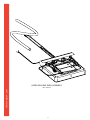
MODEL HS11
HEAT-SEAL MACHINE
WITH ELECTRONIC HEAT CONTROLS
AND LCD DISPLAY
2
Table of Contents
WARRANTY 4
EC Declaration of Conformity for Machinery
5
SECTION 1
6
Introduction to the HS11
6
Safety Information
6
Machine Specifications
7
Operating Specifications
7
SECTION 2
8
Installation and Set-Up
8
10
Machine Operation
10
Sealing Pads
12
Start-Up Screens
13
Menu Screens
14
Error Screens
15
SECTION 4
17
Operations and Problem Analysis
17
Problem Analysis and Solutions
17
SECTION 5
20
Maintenance
20
SECTION 6
21
Parts Identification and Location
21
Customer Service
67
thermopatch.com
SECTION 3
3
Warranty
thermopatch.com
Thermopatch Corporation, Syracuse, New York ("Seller")
warrants this product to be free from defects in material and
workmanship under normal use and service. Any part which
proves to be defective in material or workmanship within
one (1) year of the date of original purchase for use will be
repaired or replaced, at Seller's option, free of service or labor
charges, with a new or functionally operative part. Seller's
liability under the Warranty shall be limited to repairing or
replacing at its own factory or through an authorized service
distributor or dealer, material which is determined by Seller to
have been defective in manufacture and upon which a claim
has been made by the original purchaser or user to Seller
(or an authorized distributor or dealer) within the warranty
period. Claims under this Warranty will be honored only upon
written approval by an authorized officer of Seller. Approved
return of parts or products will be on a prepaid transportation
charges basis only. Claims under this Warranty will be
honored only upon Seller's determination that the claim is
covered by this Warranty, and Seller shall incur no obligation
under this Warranty prior to such determination. This
Warranty does not apply: (1) To any machinery or equipment
which has been altered or repaired, except by Seller or
its authorized representatives, or (2) to any machinery or
equipment which has been subject to misuse, negligence,
or accident, including, without limitation, use and operation
of such machinery or equipment while parts are loose,
broken, out of order, or damaged by the elements. Parts
replaced under this Warranty are warranted only through
the remainder of the original Warranty. Any and all claims
for warranty service must include such information as Seller
designates, and shall include specifically the serial number of
each unit (if appropriate).
The foregoing shall constitute the sole and exclusive remedy
of any using purchaser and the sole and exclusive liability
of Seller in connection with this product. THIS WARRANTY
IS IN LIEU OF ALL OTHER WARRANTIES, EXPRESS, IMPLIED
OR STATUTORY, INCLUDING BUT NOT LIMITED TO, ANY
WARRANTY OF MERCHANTABILITY OR FITNESS AND
ALL OTHER OBLIGATIONS OR LIABILITIES OF SELLER,
INCLUDING ANY TORT LIABILITY, FOR NEGLIGENT DESIGN
OR MANUFACTURE OF THIS PRODUCT, OR OTHERWISE. It is
expressly agreed that Buyer shall not be entitled to recover
any incidental or consequential damages, as those terms are
defined in the Uniform Commercial Code, and that Buyer shall
have no right of rejection or of revocation of acceptance of
any part or of revocation of acceptance of any part or all of
the goods covered hereby.
4
EC Declaration of Conformity for Machinery
(According to Annex II A of the Machinery Directive)
We,
Thermopatch B.V.
Draaibrugweg 14
1332 Almere
The Netherlands
herewith declare, on our own responsibility, that the
machinery:
heat seal machine Thermopatch HS-11
which this declaration refers to, is in accordance with the
conditions of the following Directive(s):
2006/42/EG (Machinery directive)
2004/108/EG (EMC directive)
The Netherlands, Almere, 29-09-2009
thermopatch.com
Jan Bausch,
Director
5
Section 1
Introduction to the HS11
The HS11 is designed as a heavy-duty heat-seal machine
for applying patches, emblems, hot paper transfers, and
identification tapes.
The sealing cycle is initiated by hand, which causes the
sealing head to lower.
Temperature, time, and sealing pressure can all be
individually adjusted as required for the particular materials
being sealed. Upper and lower platen temperatures can be
set independently in Fahrenheit or Celsius. A new LCD screen
with 3-button interface simplifies machine operation.
The machine develops 24 PSI inter-platen pressure with the
standard 5” x 6” platens. Two optional smaller platens are
available for even higher inter-platen pressure.
SAFETY INFORMATION
Each HS11 is equipped with a safety-lock feature for the
protection of the operator. The pneumatic sealing cycle will
not start until the upper sealing plate is within 5/32” (4mm)
of the lower sealing platen. If an obstruction is met before
this point, the sealing cycle will not occur. THE SAFETY LOCK
FEATURE IS PRESET AND SHOULD NOT BE TAMPERED WITH.
In addition to the safety lock feature, there is a touch guard
around the upper heater platen. Should any obstruction
contact the touch guard, the machine will become
inoperative. An error message will appear on the LCD screen,
see Alarm Display Screens, page 3-6.
CLEAN MACHINE PARTS WITH NON-FLAMMABLE CLEANING
FLUIDS ONLY!
CAUTION: WORKING AIR PRESSURE MUST NOT EXCEED
70 PSI (4.8 BAR)! AIR SUPPLY SHOULD NOT BE
CONTAMINATED WITH DIRT, OIL, OR WATER.
thermopatch.com
The electrical system is three-wire and fully grounded. THIS
THREE-WIRE ELECTRICAL POWER CORD AND PLUG MUST
ALWAYS BE USED WITH A PROPERLY GROUNDED OUTLET.
WARNING: THE SEALING IRONS MAY REACH TEMPERATURES
AS HIGH AS 450°F(232°C) DURING NORMAL
OPERATION. APPROPRIATE CARE SHOULD BE
TAKEN TO PREVENT SKIN BURNS. ALWAYS KEEP
HANDS CLEAR OF THE SEALING IRONS AND
TOUCH GUARDS WHEN OPERATING MACHINE!
Two back-up high limit thermostats prevent the temperature
of either sealing iron from rising above 500°F (260°C) in case
either heat control malfunctions.
Before operating, make sure all covers are in place, and keep
loose jewelry and clothing clear of machine during operation.
Before servicing machine, unplug electrical power cord,
disconnect air supply, and let sealing irons cool.
6
MACHINE SPECIFICATIONS
Electrical requirements
: 10 amp @ 110 VAC, 50/60 Hz
or
5.0 amp @ 220 VAC, 50/60 Hz
Maximum operating
air pressure
: 70 PSI
Time settings
: 1.0 – 30 seconds
Heat range
: 150°-450°F (66° - 232°C)
Shipping weight
: 65 lbs
(29.5 kg)
Length (open)
: 20”
(51 cm)
(closed)
: 23”
(58 cm)
Height (open)
: 21”
(53 cm)
(closed)
: 21”
(53 cm)
Width
: 8”
(20 cm)
Sealing iron size
: 5” x 6”
(13 x 15 cm)
(4.8 Bar)
Sealing pad size (standard) : 5” x 6”
(13 x 15 cm)*
(optional)
: 2” x 4”
( 5 x 10 cm)*
(optional)
: 1-3/16” x 4”( 3 x 10 cm)*
Pedestal (optional)
: 32”
(81 cm) high
Garment tray (optional)
: 17” x 25”
(43 x 64 cm)
*See page 11 for inter-platen pressure.
OPERATING SPECIFICATIONS
Temperature
The HS11 heat-sealing machine will require approximately
10-15 minutes for the temperature to stabilize. Check the
digital readout for upper and lower platen temperatures.
CAUTION: NEVER EXCEED 450°F (232°C), THE MAXIMUM
SEALING IRON TEMPERATURE!
thermopatch.com
Sealing temperatures
have been preset to
: 425°F (218°C) upper iron
375°F (191°C) lower iron
Time
Heat-sealing cycle time is factory set to 10.0 seconds. The
sealing time can be changed as required to apply or remove a
label.
Sealing Pressure
Sealing pressure is factory-preset at 60 PSI (4.1 Bar).
CAUTION: NEVER EXCEED 70 PSI (4.8 Bar), THE MAXIMUM
OPERATING PRESSURE!
To adjust time or temperature settings, press the MODE
key, and follow page 3-5, “Menu Screens”. To adjust sealing
pressure, see page 3-1 “Operating Instructions”.
7
Section 2
INSTALLATION AND SET-UP
Worktable Mounting
1. Set the machine on the worktable in desired location.
2. Draw a pencil line on the table at the front edge of the machine, near the center.
3. Move the machine out of the way and measure back 2” (5 cm) from the pencil line.
4. Drill a 9/32-inch (7 mm) diameter hole for a sheet metal table, or 3/16-inch (5 mm) diameter hole for a
wood table.
5. Mount the wood screw or shoulder bolt (supplied).
6. Reposition the machine so the keyhole slot in the bottom
cover (at the front) drops over the head of the screw.
7. Push the machine back slightly. (Note: The purpose of this
screw is to prevent the machine from bouncing or moving
across the table.)
Pedestal Mounting (optional)
Mount per separate instructions included with the pedestal.
Garment Tray (optional)
The garment tray can be mounted so it is either level with the
rubber platen, or reversed so it is about 5” (13 cm) below.
1. Remove two screws from each side of the machine.
2. Place the garment tray in the desired position and attach
with the four screws.
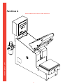
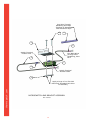
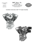
Completing the Installation
1. Attach filter assembly to air inlet at rear of machine. Use
pipe thread sealant or tape.
2. Hand-tighten or tighten lightly with a pipe wrench on the
short piece of pipe between the machine and air filter.
thermopatch.com
3. Plug the electrical power cord into a properly grounded
outlet of the correct voltage/amperage rating.
8
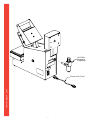
Air Filter
Pressure
Regulator
thermopatch.com
Power Line Cord
9
Section 3
MACHINE OPERATION
Operating Instructions
1. Turn the “Power” switch to ON. The amber light on the
switch will light indicating power is being supplied. Allow
approximately 10-15 minutes for the temperature to
stabilize.
2. Adjust upper and lower sealing temperatures as needed,
see page 3-5 “Menu Screens–Screen2, 3”.
WARNING: THE HEATED PLATENS MAY REACH
TEMPERATURES AS HIGH AS 450°F (232°C)
DURING NORMAL OPERATION. APPROPRIATE
CARE SHOULD BE TAKEN TO PREVENT SKIN
BURNS. ALWAYS KEEP HANDS CLEAR OF THE
HEATER PLATENS AND TOUCH GUARD WHEN
OPERATING MACHINE!
3. Adjust pressure as needed. Turn the large black knob
clockwise to increase pressure, counterclockwise to
decrease. Check air gauge and repeat as needed.
DO NOT EXCEED 70 PSI!
To Apply a Patch or Emblem (non-embroidered):
1. Set the sealing time to desired period by pressing the
up or down keypads to the proper setting (see page 3-5
“Menu Screens – Screen 4”).
2. Center the work piece over the lower sealing pad.
3. Place the patch, emblem, etc. over the work piece with
the adhesive side toward the fabric.
4. When hands are clear of the touch guard, grasp the upper
sealing head handle and lower the sealing head.
5. As soon as the upper iron comes all the way down to the
lower platen, release.
thermopatch.com
The upper iron will automatically stay down to complete
sealing. The digital display will show elapsed time for the
sealing cycle. When it reaches the set seal time, the upper
iron will automatically return to the upright position.
CAUTION: FOR BEST RESULTS, SEALED MATERIAL SHOULD
BE HANDLED CAREFULLY UNTIL IT HAS COOLED
TO ROOM TEMPERATURE.
To Remove a Patch or Emblem:
1. Set the sealing time to the desired period by pressing up
or down on the keypads (see page 3-5 “Menu Screens –
Screen 4”).
2. Place the work piece on the pad so the patch is centered.
3. Lower the upper platen until the sealing cycle begins.
4. When the upper iron releases, quickly peel the patch or
emblem off the surface of the work piece.
10
5. If the patch cools before it is removed, repeat the
procedure.
CAUTION: USE EXTREME CARE IN HANDLING THE FABRIC.
IT WILL BE VERY HOT!
Applying Embroidered Emblems
Embroidered emblems and emblems with embroidered
borders (also called Merrowed borders) are a special case and
usually should be sealed as follows:
See Section 5 “Maintenance” to remove the Teflon shield from
the upper platen and to remove the sponge rubber pad from
the lower platen.
1. Mount the Teflon shield to the lower platen and the
sponge rubber pad to the upper platen.
2. Readjust the temperatures so that the lower platen is at
410°F (210°C) and the upper platen is at 375°F (191°C).
3. Set pressure at 60 PSI (4.1 Bar) for the 5” x 6” (13 cm x
15 cm) platen.
4. Set at 12 seconds. This can be varied between 10 seconds
(for light fabrics) and 14 seconds (for heavy fabrics), see
page 3-5 “Menu Screens – Screen 4”.
5. Follow procedure for non-embroidered emblems, see
above.
thermopatch.com
Note: For very thick garments, it may be necessary to
increase the time setting even higher, since it is very difficult
to get the heat through the garment.
11
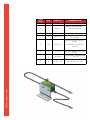
SEALING PADS
Part No.
Size
Material
Use For:
42477
42515
42516
(Standard)
(Optional)
(Optional)
5” x 6”
4” x 2”
(13 cm x 15 cm)
(10 cm x 5 cm)
Silicone sponge rubber
Silicone sponge rubber
(firm)
Silicone hard rubber
(solid)
Applying smaller-sized
heat-seal products,
or for higher sealing
pressure than standard
platen
Smallest size
applications, spot
sealing, applying labels
to confined areas of
garments, such as
between trouser belt
loops, where extremely
high inter-platen
pressure is required
Applying mending
patches, emblems, hot
paper transfers and
label tapes to garments
and linens
Gauge Air
Pressure
(10 cm x 3 cm)
INTER-PLATEN PRESSURE
PSI
(Bar)
42477
PSI
thermopatch.com
4” x 1-3/16”
42515
(Kg/cm2)
PSI
(Kg/cm2)
42516
PSI
(Kg/cm2)
15
(1.0)
5
(0.4)
19
(1.3)
32
( 2.3)
20
(1.4)
7
(0.5)
26
(1.8)
43
( 3.0)
25
(1.7)
8
(0.6)
32
(2.2)
54
( 3.8)
30
(2.1)
10
(0.7)
38
(2.7)
64
( 4.5)
35
(2.4)
12
(0.8)
45
(3.1)
75
( 5.3)
40
(2.8)
14
(1.0)
51
(3.6)
86
( 6.0)
45
(3.1)
15
(1.1)
57
(4.0)
97
( 6.8)
50
(3.4)
17
(1.2)
64
(4.5)
107
( 7.5)
55
(3.8)
19
(1.3)
70
(4.9)
118
( 8.3)
60
(4.1)
20
(1.4)
76
(5.4)
129
( 9.1)
65
(4.5)
22
(1.6)
83
(5.8)
140
( 9.8)
70
(4.8)
24
(1.7)
89
(6.3)
150
(10.6)
12
START-UP SCREENS
The HS11 heat-sealing machine is equipped with a LCD
display. When power is switched on to the machine, the
following start-up screens will be visible:
Screen 1:
THERMOPATCH
ALLIGATOR
Screen 1 is the first screen to appear when power is switched
on.
Screen 2:
TOUCH GUARD TEST
RING=123 WIRE=456
Screen 2 appears while the machine self-tests the touch
guard. Actual numbers may be different. If the touch guard
is activated, the following screen will appear. The start-up
process will continue when the touch guard is cleared.
ENSURE TOUCH GUARD
IS CLEAR #####
Screen 3:
PERFORMING SELF TEST
PLEASE WAIT
Screen 3 appears while the machine self-checks its circuits.
Screen 4:
HEATING PLEASE WAIT
UPPER 410F LOWER 375F OR
thermopatch.com
(A) UNIT READY FOR
PRODUCTION
(B)
Screen 4(A) appears while the upper and lower heat platens
are being heated to the default or user-set Fahrenheit
temperatures. If the user changes the temperature scale to
Celsius during heating, the temperatures will be displayed
in degrees Celsius (e.g. 105C). Screen 4(B) appears if the
machine is turned on while the platens are at the default
temperature.
Screen 5:
UPPER=410F TIME=10.0
LOWER=375F DC=123456
Screen 5 appears after the heat platens reach the default or
user-set temperatures. The machine is now ready to seal. The
upper and lower temperatures are shown at left, the time and
daily count (DC) at the right. To change any of these values,
see the following section “Menu Screens”.
13
MENU SCREENS
The default settings in the HS11 heat-sealing machine can be
changed as required.
To advance a menu screen, press the MODE key. To change
the value or select an option, press the up or down key. If
no button is pressed for 8 seconds, the machine will exit the
menu.
The following menu screens will appear in sequence:
Screen 1 (select temperature scale):
F/C SELECT SET=F
UP=C DN=F MODE=NEXT
Screen 1 appears when the MODE key is first pressed. The
current temperature scale is indicated in the upper right as an
“F”, for Fahrenheit (default), or “C”, for Celsius. Press the UP
key to change to Celsius. Press the DOWN key to change to
Fahrenheit. To advance to Screen 2, press the MODE key.
Screen 2 (set upper platen temperature):
SET UPPER TEMP=410F
UP=+ DN=- MODE=NEXT
Screen 2 appears when the MODE key is pressed as described
above. The upper platen temperature is displayed in the
upper right, in the temperature scale chosen at Screen
1. Press the UP key to raise and the DOWN key to lower
temperature. The temperature can be changed in 2°F or 1°C
increments.
To advance to Screen 3, press the MODE key.
Screen 3 (set lower platen temperature):
SET LOWER TEMP=375F
UP=+ DN=- MODE=NEXT
thermopatch.com
Screen 3 operates like Screen 2, setting the temperature for
the lower platen. The lower platen temperature is displayed
in the upper right (shown is the default, 375°F). The
temperature can be changed in 2°F or 1°C increments.
To advance to Screen 4, press the MODE key.
CAUTION: DO NOT EXCEED 450°F (232°C) AT EITHER
PLATEN!
Screen 4 (set seal time):
SET SEAL TIME=10.0
UP=+ DN=- MODE=NEXT
Screen 4 appears when the MODE key is pressed at Screen 3.
The seal time is shown in the upper right hand corner (shown
is the default, 10.0 seconds). The seal time can be changed
in 0.1 second increments from 1.0 to 30.0 seconds. Press the
UP key to increase and the DOWN key to decrease seal time.
To advance to Screen 5, press the MODE key.
14
Screen 5 (reset daily count):
DAILY COUNT=123456
DN=RESET MODE=NEXT
Screen 5 appears when the MODE key is pressed at Screen 4.
The daily counter, displayed at upper right, is the number of
seals since the counter was last reset. To reset the counter,
press the DOWN key, then the MODE key to advance to
Screen 6.
To continue without resetting the counter, simply press MODE
to advance to Screen 6.
Screen 6 (information and exit):
TOTAL COUNT=12345678
PRESS MODE TO EXIT
Screen 6 appears when the MODE key is pressed at Screen
5. This screen displays the total seal count, and is for
information only. The total seal count cannot be changed.
Press the MODE key to exit and resume machine operation.
ERROR SCREENS
The following screens represent error messages shown in the
digital display. Each screen is followed by an explanation of
the error, and the appropriate action to take.
Touch Guard Errors
TOUCH GUARD ACTIVE
PRESS ANY BUTTON
thermopatch.com
The touch guard has been activated by contact. Keep hands
clear of touch guard, and press any key to resume operation.
TOUCH GUARD WIRE
BROKEN-NOT FUNCTIONAL
There is a fault in the touch guard wire. This prevents the
machine from operating without the touch guard safety
feature. This message will continue to appear until the wire
is fixed. Turn off the machine, and repair the wire before
operating.
ENSURE TOUCH GUARD
IS CLEAR #####
The touch guard was activated during startup. The startup
sequence continues normally once the touch guard is cleared.
15
Hook Seal Errors
NO HOOK SEAL RELEASE
HOOKSEAL OR SOLENOID
The hook seal switch did not release within 4 seconds after
elapsed seal time. The seal made is counted, and the switch
should release the upper sealing arm automatically. This
message indicates a possible failure of the solenoid that
controls the hook seal switch.
LOST HOOK SEAL SWITCH
PLEASE TRY AGAIN
The hook seal switch lost contact before the seal cycle was
completed. The cycle is not counted. The sealing arm reset
automatically. Wait for the arm to reset, and try the seal
again.
Heater and Temperature Errors
UPPER HEATER FAILURE
LOWER HEATER FAILURE
PRESS ANY KEY
PRESS ANY KEY
The heater did not reach the set temperature in 20 minutes.
Press any key. Try to set a lower temperature. If this error
message re-occurs, there may be a more serious failure (see
Problem Analysis and Solutions).
LOWER HEATER > 250C
LOWER HEATER > 482F
FAIL – PRESS ANY KEY
FAIL – PRESS ANY KEY
UPPER HEATER > 250C
UPPER HEATER > 482F
FAIL – PRESS ANY KEY
FAIL – PRESS ANY KEY
The heater has exceeded its maximum safe temperature, or
a thermocouple or circuit board has failed. Machine operation
will stop and an alarm will sound. Press any key to silence the
alarm and return to normal mode. Shut down machine and
check thermocouple and circuit boards. Repair or replace as
needed before resuming operation of machine.
thermopatch.com
CAUTION:
HIGH TEMPERATURES CAN DAMAGE MACHINE
AND CAUSE PERSONAL HARM. DO NOT
OPERATE IF HEATER FAILURE MESSAGE
APPEARS!
16
Section 4
OPERATIONS AND PROBLEM ANALYSIS
Sequence of Operations
Connect air supply – no electrical operations; sealing head in
upright position.
Switch power on – heat goes on, switch light goes on, LCD
screen displays start-up menus.
Pull sealing head down – micro switch engages, energizing
solenoid valve, engaging sealing hook. Timer is activated and
begins counting.
Timer times out – seal arm solenoid valve is de-energized,
returning sealing platen to top position.
If power goes off (or machine is unplugged) the sealing
platen stays in the up position.
If air is removed sealing platen remains up.
PROBLEM ANALYSIS AND SOLUTIONS
Before referring to the information below, check for proper
set-up and operation as outlined in Sections 2 and 3.
Solutions are listed with the most probable ones listed first.
thermopatch.com
Some procedures may require completion by a person with
some mechanical skill. See Section 6 for Customer Service
assistance or to order replacement parts.
17
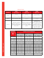
PROBLEM
Power “ON” light not
lighted
No heat
High or low heat
Sealing pressure
drops, fluctuates, or
hisses
thermopatch.com
Timed sealing cycle
does not activate
Sealing head does not
fully rise
Heat transfers or
patches, etc. not
bonded properly to
garment
POSSIBLE CAUSE
SOLUTION
-Machine is unplugged or outlet has
no power
-Check
-Electrical power switch or light is not
“ON” or is defective
-Check/Replace
-Bad fuse at power entry module
-Check/Replace
-Loose or broken wires or connections
-Check/Repair
-Machine is unplugged or outlet has
no power
-Check
-Electrical power switch is not “ON” or
is defective
-Check/Replace
-Blown fuse on circuit board
-Replace
-Defective sealing iron
-Replace
-Defective heat sensor
-Replace
-Defective temperature control
-Replace
-Defective high-limit thermostat
-Replace
-Loose or broken wires or connectors
-Check/Repair
-Defective heat sensor
-Replace
-Defective temperature control
-Replace
-Short between sensor wires (high
heat only)
-Repair/Replace
-Leak in air supply hose
-Repair/Replace
-Dust, oil, or water in air lines,
regulator, or solenoid air valves
-Disassemble and clean
-Garment or cloth is too thick
-See Section 3-3
-Leak in hose or connections
-Repair/Replace
-Defective micro switch
-Replace
-Solenoid air valve not shifting
-Disassemble and clean or
replace
-Mechanical binding
-Check/Correct
-Cracked sealing hook
-Replace
-Cracked sealing arm
-Replace
-Missing or broken pins or cam rollers
-Replace and add grease
-Loose or disconnected wiring
-Check/Correct
-Air solenoid valve not shifting
-Check/Replace
-Leak or restriction in air line or
connections
-Check/Repair
-Insufficient sealing time
-Increase time
-Insufficient sealing pressure
-Increase sealing pressure
-Insufficient temperature
-Increase temperature on
Teflon platen
-Sponge rubber pad is worn
-Replace
-Teflon cloth covers for upper/lower
platens are worn
-Clean/Replace
18
PROBLEM
SOLUTION
-Sealing time too long
-Decrease by 2 second
increments
-Sealing pressure too high
-Decrease sealing air gauge
pressure by 5 PSI or .5 Bar
increments
thermopatch.com
Adhesive bleed
through
POSSIBLE CAUSE
19
Section 5
MAINTENANCE
Teflon/Fiberglass Shield
Clean often by wiping with a soft, clean rag. A non-flammable
cleaner such as “EZ-Off”, part number DH-6873, may be
used according to the manufacturer’s instructions. Never use
a flammable solvent or abrasive cleaner! To ensure the best
heat-sealing results, regularly replace shield whenever it
becomes torn or too soiled to clean.
From the side, gently wedge a screwdriver between the
sealing iron and the aluminum backing plate. The shield may
now be removed by applying gentle pressure. Being careful
of the heat, install the new shield by holding it against the
sealing iron and pressing to snap it into position.
Rubber Sealing Pads (without Teflon Cover)
Clean often by wiping with a soft, clean rag. Replace the pad
when it becomes worn.
Note: To replace the rubber sealing pad, use the same
procedure as for the shield.
Compressed Air Supply
Maintain a filtered air supply. Check air filter daily. Drain by
pushing up on button at bottom of filter bowl.
General
Keep inside of machine free of foreign material, including lint.
thermopatch.com
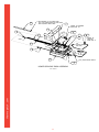
Lubrication
Place one drop of standard lubricating oil (SAE 10 or
equivalent) at the following locations once a month:
•
Pivot shafts for sealing arm: at both ends of shaft where
it enters case (See Upper Iron and Chassis Assembly)
•
Air cylinders: where the rod enters the cylinder (See
Machine Chassis Assembly)
•
Sealing hook, pins, and cam rollers: both rollers and
pins in the sealing hook and sealing arm (See Sealing
Hook and Bracket Assembly, Fulcrum Arm and Chassis
Assembly)
Be sure to wipe off any excess oil.
20
Section 6
thermopatch.com
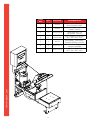
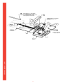
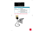
PARTS IDENTIFICATION AND LOCATION
21
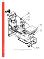
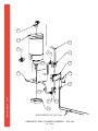
RUN WIRES #2,5 & GND THRU
ITM #18 (SHEATHING) & TAPE THIS
END w/BLACK ELEC TAPE
18
4
CONN. TO THERMO
FUSE ITM. #2
8
7
9
14
#5
10
14
3
7
#8A
#1A
GND
5
11
6
5
16
13
CONN. TO
THERMO
FUSE ITM. #2
#8
(PIGGY BACK
ON #8A)
#8A
#2
15
#2
2
5
#2
1
#1A (PIGGY BACK ON #2)
6
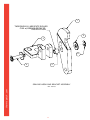
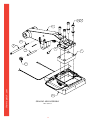
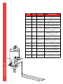
LOWER SEALING IRON ASSEMBLY
thermopatch.com
REV. 190509
22
12
17
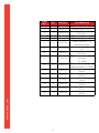
QTY.
PART NO.
DESCRIPTION
1
1
42458
IRON, SEALING
2
1
20018-11
THERMO FUSE, (500° F]
3
3
21069-03-E
PHSS #6-32UNC x ¼ STN.
STL.
4
1
41717
SHIELD, TEFLON
5
6
20003-20
¼” PUSH ON CONNECTOR
6
2
20003-28
¼” PUSH ON CONNECTOR
(PIGGY BACK)
7
2
20003-45
RING TERMINAL, #8 NONINSULATED
8
1
21021-06-B
LOCKWASHER, EXT.
TOOTH, #8
9
1
21069-03-F
PHSS #8 -32UNC x 1/4
STN. STL.
10
1
20018-14
THERMOCOUPLE, ‘J’
SERIES 36” LONG
11
1
23001-15
GROUND WIRE, 16 Ga. 12”
GREEN/YELLOW
12
1
23001-23
WIRE #1A, 16 Ga. 10”
WHITE
13
1
23001-23
WIRE #8, 16 Ga. 8-1/2”
WHITE
14
1
23001-23
WIRE #5, 16Ga. 17”
WHITE
15
2
D-3128
SPADE CONNECTOR, #6
STUD
16
1
23001-23
WIRE #8A, 16 Ga. 10-1/8”
WHITE
17
1
23001-23
WIRE #2, 16 Ga. 36”
WHITE
18
1
DH-6634
SHEATHING, FIBERGLASS
6”
thermopatch.com
ITEM
NO.
23
thermopatch.com
LOWER SEALING IRON ASSEMBLY
24
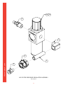
5
#4 (PIGGY BACK ON #4A)
12 17
4
#2
GND
12 16
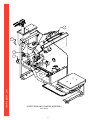
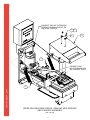
NOTE:
CONN. WIRE #2 TO THERMO FUSE,
WRAP WIRES #2, #4A & #4 TOGETHER
w/FIBERGLASS TAPE
15
#4
5
6
3
3
10
2
5
#5A
#5A
#4A
9
#5A
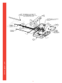
RUN WIRE No's 2, 4 &
GND THROUGH SHEATHING
ITM # 18
15
5
11
7
13
CONN. TO
THERMO FUSE
ITM. #5
5
#4A
18
6
1
8
#5 (PIGGY BACK ON #5A)
UPPER SEALING IRON ASSEMBLY
thermopatch.com
REV. 080103
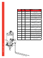
25
14
thermopatch.com
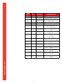
ITEM
NO.
QTY.
PART NO.
DESCRIPTION
1
1
42458
IRON, SEALING
2
1
20018-11
THERMO FUSE, (500° F)
3
3
21069-03-E
PHSS #6-32UNC x ¼”
STN. STL.
4
1
41717
SHIELD, TEFLON
5
6
20003-20
¼” PUSH ON CONNECTOR
6
2
20003-28
¼” PUSH ON CONNECTOR
(PIGGY BACK)
7
2
20003-45
RING TERMINAL, #8
NON-INSULATED
8
1
21021-06-B
LOCKWASHER EXT. TOOTH
#8
9
1
21069-03-F
PHSS #8-32UNC x ¼”
STN. STL.
10
1
20018-14
THERMOCOUPLE, ‘J’
SERIES
36” LONG
11
1
23001-15
GROUND WIRE, 16 Ga.
12” LONG
12
2
D-3128
SPADE CONNECTOR, #6
STUD
13
1
23001-23
WIRE #5A, 16Ga. 17”
WHITE
14
1
23001-23
WIRE #5, 16 Ga. 17”
WHITE
15
1
23001-23
WIRE #4A, 16 Ga. 10-1/8”
WHITE
16
1
23001-23
WIRE #2, 16 Ga. 36”
WHITE
17
1
23001-23
WIRE #4, 16 Ga. 36”
WHITE
18
1
DH-6634
SHEATHING, FIBERGLASS
6”
26
UPPER SEALING IRON ASSEMBLY
thermopatch.com
REV. 080103
27
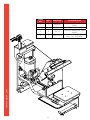
Run Wire Through
Sheathing and Tape
This End of Sheathing
With Electrical Tape
8
7
2
6
Switch Terminal
Position N.O.
Run Both Wires
Through Wire
Sheathing, Item
No.7
5
1
4
Switch Terminal
Position COM.
3
thermopatch.com
Apply a Drop of Loc-Tite 242
Into Each Threaded Hole Prior
To Assembly
MICROSWITCH AND BRACKET ASSEMBLY
REV. 240209
28
ITEM
NO.
QTY.
PART NO.
DESCRIPTION
1
1
20055-100
MICRO SWITCH, DPDT
MOUNTING BRACKET,
2
1
44214
MICRO SWITCH
3
1
40925
BAR NUT, #6-32UNC-2B
4
2
20003-34
RING CONNECTOR, #6
STUD SIZE
INSULATED ELECTRICAL
WIRE,
46”
23001-21
6
2
D-3128
SPADE CONNECTOR, #6
STUD
7
1
DH-6634
SHEATHING, FIBERGLASS
– 18” LG
8
2
21060-11-E
thermopatch.com
5
29
20 GAUGE, BLACK [23”
LG EA]
BINDER HEAD SCREW,
#6-32UNC x 1” LG
1
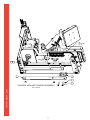
THOROUGHLY LUBRICATE ROLLER
CAM w/GREASE PRIOR TO
INSTALLATION
5
3
6
4
2
SEALING HOOK AND BRACKET ASSEMBLY
thermopatch.com
REV. 080103
30
QTY.
PART NO.
DESCRIPTION
1
1
42753
HOOK, SEALING
2
1
DH-6666
ROLLER, SEALING CAM
3
1
DH-6654
BRACKET, SEALING HOOK
4
1
D-8362
PIN, SEALING HOOK
5
2
21023-02
WASHER, PLAIN FLAT 1/4"
6
2
D-9702
RETAINING RING, TRUARC (5133-25)
thermopatch.com
ITEM
NO.
31
2
1
3
thermopatch.com
5
4
7
6
TOP PLATEN COVER ASSEMBLY
REV. 080103
32
QTY.
PART NO.
DESCRIPTION
1
1
46555
ASSEMBLY, TOP PLATEN
2
1
46554
HANDLE, TOP IRON
COVER
3
2
21061-07F-N
1/4 - 20UNC x 1" LG
BHSS
4
1
46568
ASSEMBLY, TOUCH GUARD
5
4
21028-50
SPACER, TOUCH GUARD,
NYLON
6
4
21028-51
INSULATOR, SHOULDER,
NYLON
7
4
21061-04-C
#8-32UNC x 5/8" LG
BHSH
thermopatch.com
ITEM
NO.
33
10
9
1
6
2
4
3
7
thermopatch.com
5
8
SEALING ARM ASSEMBLY
REV. 080103
34
QTY.
PART NO.
DESCRIPTION
1
1
42453
SEALING ARM, MACHINED
2
1
PM-170-3
PIN, SPRING RETAINING
3
1
21034-11-C
PIN, DOWEL (.25 DIA x
2.25 LG)
4
1
DH-6666
ROLLER, SEALING CAM
5
2
24016-17
COLLAR, LOCK
6
2
21033-09-B
PIN, ROLL (.094 DIA x
1.125 LG)
7
1
42455
BLOCK, SPACER, UPPER
SEALING IRON
8
1
Assem2
ASSEMBLY, UPPER
SEALING IRON
9
4
21021-10-C
LOCKWASHER, 5/16,
HELICAL SPRING
10
4
21050-194
5/16 - 18UNC x 2-1/4" LG
SHCS
thermopatch.com
ITEM
NO.
35
10
A
10
B
2
1
3
4
5
9
thermopatch.com
11
6
7
8
12
MACHINE CHASSIS ASSEMBLY
REV. 080103
36
ITEM
NO.
QTY.
PART NO.
DESCRIPTION
1
1
42330
WELDMENT, ASSEMBLY,
MACHINE CHASSIS
2
2
24004-12
BEARING, BRONZE
FLANGE, (Ø.625 I.D.)
3
1
22030-67
FITTING, BULKHEAD,
(¼”MNPT x ¼” FNPT)
4
1
22030-67-C
LOCKWASHER, INTERNAL
TOOTH (part of 22030-67)
5
1
22030-67-B
HEX NUT, (3/4 – 10UNC)
(part of 22030-67)
6
4
21050-185
FOOT, MACHINE CHASSIS
(70 DUR. BUNA-N)
7
4
21023-22
WASHER, #6 FLAT
8
4
21061-03-B
#6 – 32UNC x .50 LONG
BUT. HD. SOC. HEX.
9
1
42649
STRIP, TEFLON
INSULATION w/PSA
1
46573
10B
1
46862
ASSEMBLY, PNEUMATIC
SEALING CYLINDER, 230
VOLT
11
1
22005-58
FITTING, STRAIGHT,
BULKHEAD, (SPC)
12
1
21051-28-C
NUT, HEX, CYLINDER
MOUNTING, (BIMBA)
thermopatch.com
10A
ASSEMBLY, PNEUMATIC
SEALING CYLINDER, 115
VOLT
37
38
thermopatch.com
2
5
thermopatch.com
1
8
4
3
6
7
TERMINAL BLOCK DH6681-8 & TB MARKER
STRIP #DH6682-8 MOUNTED TO THE
UNDERSIDE OF SEAL HOOK PLATE
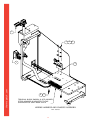
WIRING HARNESS AND CHASSIS ASSEMBLY
REV. 080103
39
QTY.
PART NO.
DESCRIPTION
1
1
46581
ASSEMBLY, WIRE
HARNESSS, POWER
ENTRY MODULE
2
1
46570
ASSEMBLY, WIRE
HARNESS, MACHINE
3
1
Assem4
ASSEMBLY, MICRO
SWITCH
4
2
21023-01
WASHER, FLAT, #10, ZINC
PLATED
5
2
21063-03-J
#10 – 32UNC x 3/8”
LONG, SOC. HD. CAP
SCREW
6
2
21021-05-A
LOCKWASHER, #6,
INTERNAL TOOTH, ZINC
PLATED
7
2
21060-08-E
#6 – 32UNC x 5/8” LONG,
BINDER HD. SCREW
8
2
21021-07-B
LOCKWASHER, #10
EXTERNAL TOOTH, ZINC
PLATED
thermopatch.com
ITEM
NO.
40
4
3
2
1
6
thermopatch.com
5
7
SEAL HOOK AND LOWER IRON ASSEMBLY
REV 080103
41
8
QTY.
PART NO.
DESCRIPTION
1
1
Assem5
ASSEMBLY, SEALING ARM
HOOK
2
1
DH-6655
PLATE, ROLLER BRACKET
3
3
21063-06-K
1/4 - 20UNC x 3/4" LG.
SOC. HD. CAP SCR.
4
3
21021-09-C
LOCKWASHER, 1/4"
HELICAL SPRING
5
1
42456
SPACER, INSULATING,
BOTTOM
6
1
Assem1
ASSEMBLY, LOWER
HEATER IRON
7
4
21021-10-C
LOCKWASHER, 5/16,
HELICAL SPRING
8
4
21050-193
5/16 - 18UNC x 2.50" LG.
SOC. HD. CAP SCR.
thermopatch.com
ITEM
NO.
42
1
4
2
3
thermopatch.com
3
UPPER IRON AND CHASSIS ASSEMBLY
REV. 080103
43
QTY.
PART NO.
DESCRIPTION
1
1
Assem8
ASSEMBLY, UPPER HEATER
IRON
2
1
42345
SHAFT, MAIN SEAL ARM
3
2
PM-37
COLLAR, MAIN SEAL ARM
SHAFT
4
2
21063-05-K
1/4 - 20UNC x 5/8" LG.
SOC . HD. CAP SCR.
thermopatch.com
ITEM
NO.
44
TB
POSITION
No. 8
4
TB
POSITION
No. 1
5
3
1
5
2
FULCRUM ARM AND CHASSIS ASSEMBLY
thermopatch.com
REV. 080103
45
QTY.
PART NO.
DESCRIPTION
1
1
42346
MOUNTING BLOCK, PIVOT
2
2
21063-10-K
1/4 - 20UNC x 1.50" LG.
SOC. HD. CAP SCR.
3
2
42347
4
3
DH-6725
PIN, PIVOT, Ø.312"
5
6
D-9704
RETAINING RING, SNAP
'E' Ø.250
thermopatch.com
ITEM
NO.
46
ARM, FULCRUM
1
6
7
5
thermopatch.com
2
4
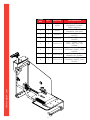
ELECTRONICS BOX, COVERS AND CHASSIS ASSEMBLY
REV. 080103
47
3
QTY.
PART NO.
DESCRIPTION
1
1
46566
ASSEMBLY, LCD/
ELECTRONICS BOX
2
1
42598
WELDMENT, ASSEMBLY,
FRONT COVER
3
6
21021-06-A
LOCKWASHER, #8
INTERNAL TOOTH
4
6
21029-48
#8 - 32UNC x 3/8" LG.
BUT. HD. SOC. HEX
5
1
46577
WELDMENT, ASSEMBLY,
LOWER HEATER GUARD
6
2
21021-07-C
LOCKWASHER, #10
HELICAL SPRING
7
2
21061-02-E
#10 - 32UNF x 3/8" LG.
BUT. HD. SOC. HEX
thermopatch.com
ITEM
NO.
48
CONNECT END OF EXTENSION
SPRING THROUGH EYELET ON
MACHINE CHASSIS
5
6
4
3
1
CONNECT END
OF EXTENSION SPRING
ON SEALING ARM PIN
thermopatch.com
2
UPPER SEALING IRON COVER, SEALING ARM SPRINGS
AND CHASSIS ASSEMBLY
REV. 080103
49
QTY.
PART NO.
DESCRIPTION
1
2
D-9704
RETAINING RING, SNAP
'E' Ø.250
2
2
24080-23
SPRING, EXTENSION,
Ø.069 MUSIC WIRE
3
1
Assem6
ASSEMBLY, UPPER HEATER
IRON COVER
4
2
21023-01-A
WASHER, FLAT, #10
(ZINC PLATED)
5
2
21021-07-A
LOCKWASHER, #10
INTERNAL (ZINC PLATED)
6
2
21061-03-E
#10 - 32UNC x .50" LG.
BUT. HD. SOC. HEX
thermopatch.com
ITEM
NO.
50
6
1
4
7
2
3
8
thermopatch.com
5
1
6
TOP AND BOTTOM MACHINE COVER INSTALLATION,
UPPER TEFLON SHIELD AND LOWER SEALING PADS
REV. 080103
51
QTY.
PART NO.
DESCRIPTION
1
4
21021-06-A
LOCKWASHER, #8
INTERNAL TOOTH
2
4
21061-02-E
#10 - 32UNF x 3/8" LG.
BUT. HD. SOC. HEX
3
4
21021-07-A
LOCKWASHER, #10
INTERNAL (ZINC PLATED)
4
1
42344
ASSEMBLY, COVER, TOP
MACHINE CHASSIS, CUST.
SERVICE
5
1
42457
COVER, BOTTOM,
MACHINE CHASSIS
6
4
21029-48
#8 - 32UNC - 3/8" LG.
BUT. HD. SOC. HEX
7
1
42477
ASSEMBLY, LOWER
SEALING PAD
8
1
40747
ASSEMBLY, UPPER TEFLON
SHIELD
thermopatch.com
ITEM
NO.
52
POWER ENTRY MODULE
CH
UPPER HEATER IRON
HTR-1
20056-33
42458
GND
ELM-1
JP3
20032-13
1
1
2
2
3
4
4
5
FU
ELM-2
10A - 250VAC
20015-37
5
6
TAS-1
20018-11
(500°F)
6
SW-1
POWER
ON/OFF
JP2
1
GND
2
2
4
20032-14
1
9
TB-1
DH-6681-8
2
3
1
4
7
5
2
8
6
RED
7
WHT
8
RED
9
WHT
1
SW-1
2
SW-1
2
HTR-2
LOWER HEATER IRON
HTR-2
GND
42458
ELM-3
HTR-1
ELM-4
SOL-1
ELECTRONICS/LCD
ENCLOSURE
46566
4
4
HTR-1
5
5
HTR-2
6
6
SOL-1
7
7
LS-1
8
8
LS-1
TAS-2
20018-11
(500°F)
2
5
2
6
PLR-1
9
40245 (PLUG)
&
40246 (RECP)
3-P
ACTIVATE PNEU. CYL.
SOL-1
PNEUMATIC SOLENOID VALVE
22046-18
7
thermopatch.com
9
TC-1
LOWER HTR IRON
HTR-2
TC-2
UPPER HTR IRON
HTR-1
THERMOCOUPLES
8
DISENGAGE SOL-1
TGC-1
TOUCH GUARD
46568
20018-14
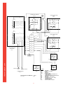
ELECTRICAL SCHEMATIC - 110v
REV. 240209
#46589
53
LEGEND
CH
ELM
FU
GND
HTR
JP
LS
PLR
SOL
SW
TAS
TB
TC
TGC
-
ENGAGE SOL-1
LS-1
MICROSWITCH
20055-100
CHASSIS
ELEMENT, HEATING
FUSE
GROUND
HEATER, IRON
CONNECTOR, JUNCTION PLUG
LIMIT SWITCH
CONNECTOR, PLUG & RECEPTACLE
SOLENOID, PNEUMATIC
SWITCH
THERMOFUSE (HIGH LIMIT)
TERMINAL BLOCK
THERMOCOUPLE
TOUCH GUARD CIRCUIT
POWER ENTRY MODULE
CH
UPPER HEATER IRON
HTR-1
20056-33
42458
GND
JP3
20032-13
1
1
2
2
3
4
4
5
FU
5
6
ELM-2
ELM-1
5A - 250VAC
20015-31
TAS-1
20018-11
(500°F)
6
SW-1
POWER
ON/OFF
JP2
1
GND
2
2
4
20032-14
1
9
TB-1
DH-6681-8
2
3
1
4
7
5
8
6
RED
7
WHT
8
RED
9
WHT
2
1
SW-1
2
SW-1
2
HTR-2
LOWER HEATER IRON
HTR-2
GND
42458
HTR-1
ELM-3
SOL-1
ELECTRONICS/LCD
ENCLOSURE
46566
4
4
HTR-1
5
5
HTR-2
6
6
SOL-1
7
7
LS-1
8
8
LS-1
TAS-2
20018-11
(500°F)
2
5
2
6
PLR-1
9
40245 (PLUG)
&
40246 (RECP)
3-P
ACTIVATE PNEU. CYL.
SOL-1
PNEUMATIC SOLENOID VALVE
22046-22
7
9
TC-1
LOWER HTR IRON
HTR-2
TC-2
UPPER HTR IRON
HTR-1
THERMOCOUPLES
8
DISENGAGE SOL-1
TGC-1
TOUCH GUARD
46568
thermopatch.com
20018-14
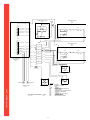
ELECTRICAL SCHEMATIC - 220v
REV. 240209
#46593
54
LEGEND
CH
ELM
FU
GND
HTR
JP
LS
PLR
SOL
SW
TAS
TB
TC
TGC
-
ENGAGE SOL-1
LS-1
MICROSWITCH
CHASSIS
20055-100
ELEMENT, HEATING
FUSE
GROUND
HEATER, IRON
CONNECTOR, JUNCTION PLUG
LIMIT SWITCH
CONNECTOR, PLUG & RECEPTACLE
SOLENOID, PNEUMATIC
SWITCH
THERMOFUSE (HIGH LIMIT)
TERMINAL BLOCK
THERMOCOUPLE
TOUCH GUARD CIRCUIT
ELM-4
5
1
9
5
6
8
10
3
12
2
4
thermopatch.com
11
13
7
8
55
QTY.
PART NO.
DESCRIPTION
1
1
42319
PNEUMATIC CYLINDER,
SEAL ARM
2
1
46551
MOUNTING BRACKET,
SOLENOID VALVE
3
1
22046-18
SOLENOID VALVE, 4-WAY
110/50-120/60 VAC
4
1
46569
WIRE ASSEMBLY, MAC
JACK
5
2
22015-38
PNEUMATIC FITTING, 90°
ELBOW, ¼” TUBE x 3/8”
MNPT
6
1
22005-57
PNEUMATIC FITTING,
STRAIGHT, ¼” TUBE x
1/8” MNPT
7
1
22046-20
PNEUMATIC MUFFLER,
BRASS, #10-32UNC
8
2
22015-39
PNEUMATIC FITTING, 90°
ELBOW, ¼” TUBE x 1/8”
MNPT
9
1
22035-19
PNEUMATIC TUBING, ¼”
O.D. x 6” LONG, BLACK
10
1
22035-19
PNEUMATIC TUBING, ¼”
O.D. x 6” LONG, BLACK
11
1
22035-19
PNEUMATIC TUBING, ¼”
O.D. x 7.5” LONG, BLACK
12
2
21063-07-D
#5 – 40UNC x 7/8” LONG,
SOC. HEX CAP SCREW
13
1
21051-28-C
HEX NUT, CYLINDER
MOUNTINGF
thermopatch.com
ITEM
NO.
56
5
1
9
5
6
8
3
10
2
12
4
thermopatch.com
11
8
7
13
WIRE LENGTH 18" [45.7cm]
PNEUMATIC SEAL CYLINDER ASSEMBLY - 230 volt
REV 031209
57
QTY.
PART NO.
DESCRIPTION
1
1
42319
PNEUMATIC CYLINDER,
SEAL ARM
2
1
46551
MOUNTING BRACKET,
SOLENOID VALVE
3
1
22046-22
SOLENOID VALVE, 4-WAY
24 VOLT DIRECT CURRENT
4
1
47086
WIRE ASSEMBLY, MAC
JACK
5
2
22015-38
PNEUMATIC FITTING, 90°
ELBOW, ¼” TUBE x 3/8”
MNPT
6
1
22005-57
PNEUMATIC FITTING,
STRAIGHT, ¼” TUBE x
1/8” MNPT
7
1
22046-20
PNEUMATIC MUFFLER,
BRASS, #10-32UNC
8
2
22015-39
PNEUMATIC FITTING, 90°
ELBOW, ¼” TUBE x 1/8”
MNPT
9
1
22035-19
PNEUMATIC TUBING, ¼”
O.D. x 6” LONG, BLACK
10
1
22035-19
PNEUMATIC TUBING, ¼”
O.D. x 6” LONG, BLACK
11
1
22035-19
PNEUMATIC TUBING, ¼”
O.D. x 7.5” LONG, BLACK
12
2
21063-07-D
#5 – 40UNC x 7/8” LONG,
SOC. HEX CAP SCREW
13
1
21051-28-C
HEX NUT, CYLINDER
MOUNTINGF
thermopatch.com
ITEM
NO.
58
1a 1b
2
3
4
thermopatch.com
6
5
AIR FILTER PRESSURE REGULATOR ASSEMBLY
REV. 080103
59
ITEM
NO.
QTY.
PART NO.
DESCRIPTION
1a
1
22045-91
AIR FILTER PRESSURE
REGULATOR GAUGE, (0 –
120 PSI)
1
22045-94
2
1
DH-6797
HOSE ADAPTER
3
1
22015-40
STREET ELBOW, 90°, ¼”
MNPT x ¼” FNPT
4
1
22030-67
BULKHEAD FITTING, ¼”
FNPT x ¼” FNPT
5
1
22005-58
PNEUMATIC STRAIGHT
FITTING, ¼” TUBE x ¼”
MNPT
6
1
DH6766
BRASS NIPPLE FITTING,
¼” MNPT x ¼” MNPT
thermopatch.com
1b
AIR FILTER PRESSURE
REGULATOR GAUGE, (0 –
10 BARS)
60
15
RUN WIRES #1,7, GND WIRE
& THERMOCOUPLE THRU
ITM #15 (SHEATHING) & TAPE THIS
END w/BLACK ELEC TAPE
4
5
7
10
13
10
6
#7
9
THERMOCOUPLE
5
2
#1
#14
GND
3
8
6
CONN. TO THERMO
13 FUSE ITM. #2
#14
5
16 13
#1
14
12
CONN. TO THERMO
FUSE ITM. #2
#8
#8
thermopatch.com
1
61
ITEM
NO.
QTY.
PART NO.
DESCRIPTION
1
1
42458
IRON, SEALING
2
1
20018-11
THERMO FUSE, (500° F)
3
3
21069-03-E
PHSS #6-32UNC x ¼”
STN. STL.
4
1
41717
SHIELD, TEFLON
5
6
20003-20
¼” PUSH ON CONNECTOR
6
2
20003-45
7
1
21021-06-B
LOCKWASHER EXT. TOOTH
#8
8
1
21069-03-F
PHSS #8-32UNC x ¼”
STN. STL.
9
1
20018-14
RING TERMINAL, #8
NON-INSULATED
THERMOCOUPLE, ‘J’
SERIES
36” LONG
GROUND WIRE, 16 Ga.
1
23001-15
11
1
23001-23
WIRE #8 16Ga. 8-1/2”
WHITE
12
1
23001-23
WIRE #7, 16Ga. 17”
WHITE
13
2
D-3128
SPADE CONNECTOR, #6
STUD
14
1
23001-23
WIRE #14, 16 Ga. 10”
WHITE
15
1
DH-6634
SHEATHING, FIBERGLASS,
6” LG.
16
1
23001-23
WIRE #1, 16 Ga. 21”
WHITE
thermopatch.com
10
62
GREEN/YELLOW 12” LONG
63
thermopatch.com
15
RUN WIRES #1, #6, GND WIRE
& THERMOCOUPLE THRU
ITM #15 (SHEATHING) & TAPE THIS
END w/BLACK ELEC TAPE
4
5
7
10
13
10
6
#6
9
THERMOCOUPLE
5
2
#1
#15
GND
5
8
6
CONN. TO THERMO
12 FUSE ITM. #2
#15
#15
16 13
5
#1
14
12
CONN. TO THERMO
FUSE ITM. #2
#5
#5
thermopatch.com
1
64
QTY.
PART NO.
DESCRIPTION
1
1
42458
IRON, SEALING
2
1
20018-11
THERMO FUSE, (500° F)
3
3
21069-03-E
PHSS #6-32UNC x ¼”
STN. STL.
4
1
41717
SHIELD, TEFLON
5
6
20003-20
¼” PUSH ON CONNECTOR
6
2
20003-45
RING TERMINAL, #8
NON-INSULATED
7
1
21021-06-B
LOCKWASHER EXT. TOOTH
#8
8
1
21069-03-F
PHSS #8-32UNC x ¼”
STN. STL.
9
1
20018-14
THERMOCOUPLE, ‘J’
SERIES
36” LONG
10
1
23001-15
GROUND WIRE, 16 Ga.
GREEN/YELLOW 12” LONG
11
1
23001-23
WIRE #5 16Ga. 8-1/2”
WHITE
12
1
23001-23
WIRE #6, 16Ga. 26”
WHITE
13
2
D-3128
SPADE CONNECTOR, #6
STUD
14
1
23001-23
WIRE #15, 16 Ga. 10”
WHITE
15
1
DH-6634
SHEATHING, FIBERGLASS,
15” LG.
16
1
23001-23
WIRE #1, 16 Ga. 40”
WHITE
thermopatch.com
ITEM
NO.
65
66
thermopatch.com
Customer Service
Thermopatch Corporation’s U.S. and International network
of sales representatives, as well as its internal Customer
Service Department, offer their assistance in the development
of effective heat-seal mending, marking, and identification
programs.
Thermopatch markets a complete line of heat-seal and
marking machines, as well as a complete line of materials and
supplies.
Label Printing Machines – manual, automatic, and
computer-controlled.
Marking Machines – high-speed permanent imprinting of
decorative or informative marks on most woven fabrics.
Heat-Seal Machines – manual, semi-automatic, and fully
automatic, with high inter-platen pressure to assure
excellent adhesion of label tapes and mending materials.
Mending Materials – hundreds of weights, colors, weaves,
and fibers to match most industrial and institutional
fabrics.
Label Tapes – specially woven 100% cotton and blends
with adhesives to match specific processing requirements.
Emblems – high quality blank emblems with screen print or
merrowed borders.
Hot Paper Transfers – in sizes from 1 to 100 square inches
in rolls or cut and stacked. Custom or stock designs in one
to four colors.
When ordering machine parts, please include the model and
serial number of the equipment.
thermopatch.com
U.S.A.:
Thermopatch Corporation
P.O. Box 8007
Syracuse, New York 13217-8007
Phone:
315-446-8110
Fax:
315-445-8046
Toll Free:
800-252-6555 (U.S.A. only)
Canada:
Thermopatch (Canada) Inc.
25 Groff Place, Unit 5
Kitchener, Ontario N2E 2L6
Phone:
519-748-5027
Fax:
519-748-1543
Toll Free:
800-265-6416 (Canada only)
Australia:
Thermopatch (Australia) Inc.
Unit 9, 477 Warrigal Road
Moorabbin, Victoria 3189
Phone:
011-61-3-532-5722
Fax:
011-61-3-532-5652
67
Netherlands:Thermopatch BV
Draaibrugweg 14
P.O. Box 50052
Almere 1332 AD
Netherlands
Phone:
011-31-36-549-1111
Fax:
011-31-36-532-0398
Germany:
Thermopatch Deutschland GmbH
Grunteweg 33
26127 Oldenburg
Germany
Phone:
011-49-441-380210
Fax:
011-49-441-3802121
France:
Thermopatch France
7 Rue Chappe-Z.I. Des Garennes
B.P. 1011
Les Mureaux Cedex 78131
France
Phone:
011-33-1-3022-0808
Fax:
011-22-1-3022-1866
Internet Address: http://www.thermopatch.com
thermopatch.com
E-mail address:
68
[email protected]
thermopatch.com
Thermopatch Corporate Headquarters
Thermopatch European Headquarters
Thermopatch Australia Pty Ltd
Thermopatch Canada Inc
Kannegiesser UK Ltd.
USA
The Netherlands
Australia
Canada
United Kingdom
T
T
T
T
T
+1 315 446-8110
+31 36 549 11 11
+61 395325722
+1 519 748-5027
+44 1539 722122
F
F
F
F
F
+1 315 445-8046
+31 36 532 03 98
+386 2 80 55 232
+1 519 748-1543
+44 1539 721000
[email protected]
[email protected]
[email protected]
[email protected]
[email protected]