1
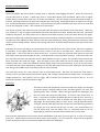
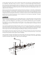
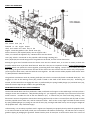
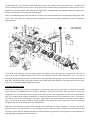
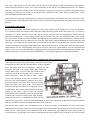
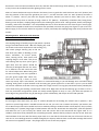
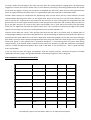
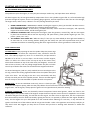
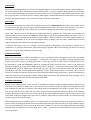
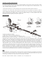
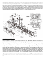
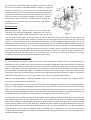
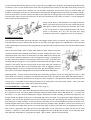
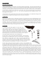
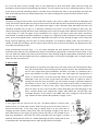
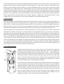
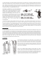
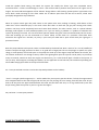
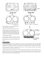
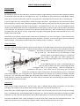
SERVICE AND MAINTANENCE TIPS
WATER PUMPS
A Cautionary Tale:
We had left St. Peter Port that afternoon, and motored against a light Northerly wind which still managed to produce
unreasonably steep seas with the wind against the tide. Our Bowman 26 was powered by a Sabb Model H diesel,
and as we set course for Salcombe I realised it was going to be a long slog with just the main up as a steadying sail.
It was just after two in the morning when I heard the engine slow down. A quick glance at the instruments and my
heart dropped as I saw the water temperature gauge well over boiling. Shouting to my wife to cut the engine, I lifted
the cover to be greeted by the smell of burning paint. We wallowed for an hour, too near the shipping lanes for
comfort, whilst with the aid of a torch I stripped down the water pump, to discover that a special strainer I had fitted
in the inlet pipe, was blocked by a mixture of salt deposits and little barnacles. After clearing this out, and ensuring
the engine was cool and free to turn, we got under way again, feeling glad that she hadn’t decided to seize in the
middle of the Little Russell!
The moral I learnt from this episode is that a little routine maintenance can save a lot of panic. I hadn’t looked at the
pump or filter since I installed the engine three years previously. However, as well as having the necessary tools and
spares on board, I knew where the water pump was, and how to take it to pieces... ... Do you?
HOW THEY WORK
The same diaphragm operated pump is fitted to most engines in the Sabb range and located on the port side, half
way back, close to the engine beds. The pump rod (9) is driven in and out by an eccentric shaft, and slide in the bore
of flange (7). The centre of a neoprene rubber diaphragm (4) is fixed to this
rod by screw (3). The outside rim of the diaphragm is held
between flange (7) and pump housing (1). Clamped to
the housing is valve block (18), which contains two
plastic mushroom-shaped valves (17) held closed by
springs (16).
As the diaphragm pulls in, water is sucked through the
inlet (23), past the lower inlet valve, and through the lower
rectangular hole in the pump housing. When the diaphragm is
pushed out, the water is forced back into the valve block, past the upper
outlet valve, through the upper circular hole in the pump housing, which is connected
to the outlet pipe (42). The ‘O’ ring (6) fits in a groove along the bore of flange (7), to prevent oil leakage along the
pump rod. The space behind the diaphragm is vented by holes drilled in the rim of flange (7), so should any oil or
water get there, it will run out underneath. Two drain cocks (2) are fitted in the pump housing, the upper one drains
the engine, the lower one the pump.
VARIATIONS
Single cylinder engines fitted with a fuel lift pump, have a different flange which incorporates the fuel pump
mounting, and a longer screw (3) which holds washers and spacers to drive the lift pump arm.
Some fresh-water cooled engines have double water pumps, one to circulate the fresh water for exhaust cooling.
This is a combined affair, with two diaphragms of different sizes, and two identical valve blocks, on engines of 18HP
and below. On the 22HP and 30HP engines, two standard water pumps are fitted, one on each side of the engine.
Occasional installations have a heat exchanger to cool the fresh water, rather than the standard keel-cooler. On
these, the sea water circuit is pumped by a separate rubber vane type pump, driven by the ‘V’ belt.
REPAIRS AND MAINTENANCE
Valve Block
The usual problem with these pumps is weed, mud, or especially sand clogging the valves. Grains of sand tend to
jam the valve stem in its hole. A while ago, valves in a hard black plastic were introduced, whose stem is slightly
smaller than the earlier white nylon ones, to reduce this tendency. Also the springs are now of identical strength, in
stainless, replacing the bronze set which had a weaker inlet valve spring. Removing the block is simple if you can get
at it, and the boat-builder has allowed room. Unfortunately many yacht installations we come across are such that
you can see the pump or feel it – but not both at the same time!
Turn off the seacock, and undo the water inlet pipe from the elbow at the bottom of the valve block. Undo nuts
(27), which are ½” A/F on engines made before June 1976, and 13mm since then. Remove the clamp bar, valve block
complete, and gasket. You really need a vice to take the valve block to pieces, as they are often done up very tightly.
Remove the elbow (23), keeping the copper washers which have been selected in thickness to ensure the inlet points
the right way when tightened. Now undo the valve seat (19) and plug (15), noting that these have a metal to metal
contact with no sealing washers. Remove valve springs and valves, and clean weed, barnacles, salt and so forth from
the block.
Even with new valves and springs, the pump outlet will be reduced if the brass surface of the valve seats is grooved
or corroded. If the original white valve has worn a recess in the seat, a new black one – which has a head very
slightly larger – may in fact leak more than the old one. To test the inlet seat, hold the valve against its seat with
your finger, whilst you blow through the inlet, - preferably after having washed the mud out! To test the outlet seat,
first screw the inlet valve seat (19) back onto the block without its valve or spring. Put the outlet valve back into the
block, and hold it shut with your finger. Press the finger of your other hand over the two lower holes in the block
and blow in the inlet. Both seats should be virtually airtight, and if not need resurfacing. If you do not have access
to a lathe, the inlet can be improved by rotating it on fine wet & dry paper laid on a piece of flat glass, but the outlet
seat, being in the middle of the valve block body, has to be machined.
The studs (26), all the nuts, and clamp bar (25) are often badly rusted. We have now had these parts made in
stainless steel to suit both imperial and metric engines, and strongly recommend you change them. Re-assembly is
straight forward, fit a new gasket if yours is soggy, and be careful to fit the block so the holes line up. It is not
located up and down, and can be fitted too high.
Diaphragm
These do not often fail completely, unless the inside of the engine is so bunged
up that the pump is working under pressure, but with age they can crack, still
pumping water after a fashion. Water then gets behind the diaphragm, and
runs out under the pump (see illustration), so make a visual check every so
often. It is prudent to replace the diaphragm every couple of years, and carry a
spare on board. You do not have to remove the valve block to get at the
diaphragm, but with limited space it is often easier. Having disconnected the
inlet pipe, and the outlet pipe (42) from the top of the pump housing, undo the
two larger nuts (13), which are 9/16” A/F or 17mm. The pump housing can
now be eased away from the flange, but it is sometimes loath to let the
diaphragm go, which must be prised out carefully with a screw driver.
Next undo the diaphragm screw (3) with a decent wide-bladed screw driver if you can get it in, or a pair of vice-grips
if you can’t. Check that the screw has not de-zincified – gone coppery – if it has, replace it. Don’t lose the large brass
washer (5) which fits with its curved face towards the back of the diaphragm.
On most engines the water pump is driven at half the engine speed, and is fitted with a moulded diaphragm which
has “Sabb 842ff – Motor Side” written on one face. It means it! On 22HP and 30HP engines fitted with either a
direct drive gearbox, heavy-duty gearbox with 2 to 1 reduction box on the end. Hurth gearbox or hydraulic variable
pitch gear, the pump works at full engine speed, and a thick diaphragm is fitted, which goes either way round. If the
space behind the diaphragm is thick with oil, go to the next section, otherwise fit the new diaphragm and don’t overtighten the screw, it’s only brass.
Whilst you have the pump housing off, make sure that the drain cocks work freely. The thread is ⅛” BSP should the
holes need tapping out, and a bit of grease or Copperslip on them works wonders. On some engines the end of the
drain cock is fitted with a small nylon plug. We have known odd occasions when this plug gets left behind, and stays
sealing the hole when draining down for the winter, so if little or no water come out, it is worth slackening the outlet
pipe just to be sure. Refit the pump housing – there is no gasket here as it seals against the diaphragm – and tighten
the nuts evenly. Reconnect the water pipes.
‘O’ Ring Renewal
Before removing the pump flange (7), screw a wooden dowel, pencil, or 5/16 UNC bolt about 4” long into the pump
rod (9). This stops it disappearing inside the engine when the flange is removed, from where it is a devil of a job to
retrieve. On 2G and 2J engines this is not necessary. Two ‘O’ rings were fitted after 1971, and one previously.
Removing them is a bit of a fiddle, best done with the flange in a vice, using two small screwdrivers to stretch the
ring sufficiently to slip a piece of wire between it and its groove – a three handed operation. Working the new ones
in is much easier.
Clean remnants of gasket (8) off the flange and engine, and fit a new one using a little grease only. Oil the pump rod,
and replace the flange, ensuring the counter sunk oil hole is on top. It should be noted that if the back of the water
pump is thick with oil, and the engine generally is leaking oil from behind the flywheel, and around the air intake,
then the signs are that the crankcase is getting pressurised by piston blow-by, and a major overhaul is due.
When starting for the first time, ensure the sea cock is open, and drain cocks closed. Run at just over tick over until
you see water coming out of the exhaust, which can take up to a minute, and seems like an hour! For the record,
the output of these pumps is about a gallon a minute at 1000RPM.
Finally remember that engine overheating may be caused by other factors than water pump failure. The favourite is
a blocked water inlet fitting, and salted up internal water passages and a build up of rust and debris between
cylinder liner and block is quite common in older sea water cooled engines.
CONE TYPE GEARBOXES
How
They Work
The ‘ahead’ cone (15) is
fastened to the engine output
shaft, and rotates the same way as the
engine. Inside the gearbox is the ‘ahead’ cone (25),
which is driven by the layshaft (50) by one set of gears and a
chain, so it rotates the opposite way. Between these two the driven
cone (19), which is connected to the propeller shaft through coupling (35).
Parts (16) & (20) are Ferodo linings which are glued into the ahead, and rear of the driven cone.
Pushing the gear lever forwards moves the driven cone into the ‘ahead’ cone, so it starts to rotate, as does the
propeller which starts to push the boat forward. Now this is the part it is important realise, it is the thrust from the
propeller which now pushes the cones together, preventing them from slipping. Astern works in exactly the same
way. Pulling the gear lever back moves the back of the driven cone into contact with the astern cone, the propeller
starts to pull the boat astern, and this holds the cone together. You will note the whole propeller shaft moves some
¼” (6mm) between ahead and astern.
The gearlever mechanism works by rotating shaft (60) into which is eccentrically fitted a hardened dowl (61). This
engages in a slot in the bearing carrier (30), which is fitted to the shaft of the driven cone (19). Positioning of
neutral, and the initial force to engage the cones, is performed by the spring loaded plunger (71) and little lever (70),
which fits into the top hole just visible in the gearshaft (60).
PROBLEMS ASSOCIATED WITH EARLY GEARBOXES
The box illustrated above was first produced in 1965, and fitted to all engines in the Sabb range until 1971, when a
stronger version was introduced. “Why did they design it?” you might ask, especially if you own one of one of the
earlier versions. Consider the life of the two ballraces (31). In neutral they are static and doing nothing. The
fisherman’s boot on the gearlever moves their housing (30) forward, so there is an axial (fore and aft) load on them
until the propeller thrust takes over, and he removes his boot. There is then a very slight axial load on them caused
by spring-loaded plunger (71) acting on one side of lever (70), and slight side load as they are carrying the weight of
the propeller shaft. They should be happy!
Unfortunately, it is not always a perfect world. Engines are frequently not properly lined up with the propeller shaft,
or can move around on their beds, which puts a tremendous side load on the bearings. The lad who tries to stop his
gearbox slipping by wedging the gearlever forward with a piece of wood put an axial load on them far in excess of
the designed load. The yachtsman with semi-sized remote control cable creates the same effect. To add to their
misery, instead of running in nice clean oil, they often have to contend with an emulsified sea water mixture, as the
gearbox has been operated in semi-submerged in bilge water. In desperation they collapse, and if you replace them
without correcting the cause, they will collapse again.
There is a modification that can be carried out, where the two poor little ballraces are replaced by tough taper roller
races. This is an expert job, requiring some machining on a lathe, but is worth considering if you are having the
above problem.
In the 1971 version (above), a much stronger double row angular contact bearing (16) is incorporated. Two rear oil
seals (19) & (20) are fitted instead of one, and a more positive neutral indent mechanism. The easy way to
distinguish which gearbox you have is to look for this spring plunger housing which is just aft of the lid, next to the oil
filler plug. On the early box, the spring is under a brass plug which looks identical to the filler, thereas on the later
type it is in a separate 3” (80mm) high housing (76).
THE WELL-GEARBOX CLINIC
Remove the oil filler plug, and look at the dipstick. It should show clean oil up to the mark. If it is black, the oil seal
which separates the gearbox from the engine is leaking (or some clot has filled it with old sump oil, which has
happened!) If it is creamy white, water has got inside, either past the rear or gearlever oil seals, past in imperfect lid
seal, or on single cylinder engines through the air intake and down the slots for the hand start chain. If the level is
low, look for signs of oil seal leakage in the bilges. Again only on the single cylinders, if oil wells out of the box as
soon as you remove the plug, the above clot has topped up the engine oil via the rocker cover rather than through
the plug in the side of the engine with ‘OIL’ stamped on it.
Next move the gearlever forwards and backwards whilst watching the output coupling. It should move as the
gearlever moves. Any ‘lost motion’, i.e. the coupling only moves when the lever is fully forward, and stays put until
the lever is nearly fully aft, indicates the demise of those ballraces, general slop in the gearlever shaft and dowel, or
that the output coupling nut has worked loose.
Now take a tape measure, and write down how far the top of the gearlever moves horizontally from neutral to
ahead, and from neutral to astern. The correct movement for the top of a 19” (482mm) gearlever is 3¼” (83mm)
each way. This figure increases as the cone linings wear, and when it reaches 4½” (115mm) the gearbox needs
adjusting, or it will soon start to slip. For cut down levers, as found on some yachts, work it out pro-rata, - a lever
have as long should move half as much.
Finally check to see nothing is preventing free movement of the gearlever or propeller shaft, such as too short a slot
for the gearlever in the engine box, stiff remote controls, or miles of fishing line packed around the shaft by the stern
bearing.
ADJUSTMENTS AND REPAIRS
All work on the gearbox, apart from replacing oils seals, means taking it off the engine, and as it has to move back
4½” (115mm) to clear, this usually means tilting the engine forward in power boats, and engine out – or at least in
the saloon – in a yacht. Overalls on then, lads, and here we go. First job, undo the coupling bolts, slide the shaft aft
and check the alignment. If it goes ‘poing’, and springs to one side, that’s why you’re having trouble! There should
be ½ litre of oil in the box, so if you care about your bilges drain it via the drain plug, or pump it out. Remove the lid,
and turn the flywheel until the chain joint link is on top, then undo it without dropping the three little plates and
spring clip. If just adjusting the ahead motion, tie the ends of the chain to the gearbox feet, otherwise remove it.
Lift out the layshaft, retaining the small rubber discs that seal the front of it. If doing more than just adjusting the
ahead motion, the rear coupling flange will have to come off, and now is a good time to clear the tabwasher and
slacken its nut, as you can lock the shaft by engaging ahead, and sticking a piece of wood through the flywheel. Next
undo the five bolts – two either side and one underneath – which hold the gearbox on, and pull it aft and off.
STRIPPING AND ADJUSTING ASTERN MOTION – 1965 Box (Nos. Refer to drawing on page 4)
Undo plug (73), remove spring and plunger, then lift out lever (70) by
hooking piece of bent stiff wire through hole in its top. Gearlever,
shaft, and dowel now pull out sideways. Remove nut (37)
previously loosened, and coupling flange (35), which may
need a puller if tight. Lift out its key (22), the drive cone
comes out forwards and bearing carrier, spacers and
shims backwards. Prise out old oil seals. Check
‘astern’ cone bearings. If you have had water in the
box they may need changing, otherwise they don’t
give much trouble. To remove this cone you will need
large circlip pliers and a gear puller. Three types of
bearing carrier (30) have been used. Originally it was a
straight sleeve, and a square-ended dowel bore directly
against the out races. Most are like the sectional
drawing with internal shoulder, and if the box has been
modified, one accepts the larger taper roller bearings.
Whichever you have, it is important to ensure that the
spacer
(32) and any shims with it are present and undamaged, so when the coupling nut is tightened, you do not load the
bearings, it would be prudent to change them even if they seem O.K.
The position of the ‘astern’ cone, and bearing carrier in neutral, are fixed. To compensate for wear to the astern
lining therefore, the driven cone must be moved slightly aft, and this is done by removing shims from in front of the
bearing carrier. These shims are then refitted in front of the ‘ahead’ cone, plus additional ones to take up wear on
the ahead lining. The gearbox can continue to be adjusted until the ‘ahead’ cone nut starts to run out of threads
because the cone has been moved that much aft, and then the Ferodo linings need replacing. This is not a D.I.Y job,
as they have to be machined true after glueing into the cones.
Shims of various thicknesses may be found in the boxes, but as a guide the usual thick ones are 0.25” (0.6mm) and
alter the position of the top of the gearlever just over 1”, and the usual thin ones are .010” (0.25mm) and alter it
about ½” (13mm). Now as you know the original movement, because you wrote it down, didn’t you, you can
estimate how many shims to remove to bring it back to 3¼” (83mm). Temporarily re-build the box, fitting shims,
bearing carrier & spacer, coupling flange and nut, but omitting key and oil seals. Refit gearlever, dowel, and plunger
assembly, and test the movement. You will probably take two or three alterations of the shims to get it exactly right,
and don’t be tempted to settle for less movement than specified or the box may jump out of gear on you at low revs.
When happy, fit new oil seals with a bit of grease on them, and finally the coupling flange with its key and new lock
washer.
Adjusting Astern. Differences with 1971 Box
(Numbers Refer to Drawing on Page 5)
The coupling flange is fixed by ring nut (24) which is undone
using a flat-ended metal chisel. With the coupling off, undo
the 4 bolts and remove separate oil seal housing (11),
then whole plunger housing (76) to fish out
little lever (70). When re-building, to test
astern movement, fit narrow spacer,
shims, bearing carrier, wide spacer and
coupling flange in that order. Only fit oil
seal housing and key when you’ve got it
right. Note that the spacers should be
renewed if damaged and that the shims
are a different size and cannot be used
for ’ahead’ adjustment. When fitting new
oil seals in housing, inner one is pushed in
just past grease nipple hole. Outer one,
which has a dust lip, is flush. Fit them
same way round, ‘open’ side inwards, not shown on sectioned drawing or you will damage inner seal when fitting
coupling. Pack grease in space between seals and only give grease nipple one or two shots a year or you can blow
the seal out. Gearlever shaft has a brass ring which fits a larger oil seal. This ring (42) sometimes breaks probably due
to the shaft rusting and swelling. The box then trades oil for bilge water and all the bearings go, so check it. To fit a
new one, hold shaft and gearlever (which are usually rusted together as one) in a vice, jaws level with position of
outer edge of ring. Expand new ring by warming it up with a blowlamp, and drop it on bevel and upwards.
ADJUSTING AHEAD MOTION. ALL BOXES.
As the engine drive shaft sticks out some 3” (76mm) beyond the nut holding the ‘ahead’ cone in position, a box
spanner or special long socket is needed to undo the nut. No, you can’t use a hammer and chisel, you butcher! The
nut is 36mm across flats and a suitable tool can be made by sawing a standard socket in half (Jap one, they’re softer)
and welding a 2½” (65mm) long length of tube between the two bits. Knock back the tab washer, spike the flywheel
and undo the nut. If you are lucky the ‘ahead’ cone will now be able to be levered off the engine shaft. If it is
stubborn it will have to be pulled off with a suitable gear puller. Remove the key and prise out the oil seal. Clean the
shaft and bore of the cone with fine emery paper until it is a nice slide fit. Check that the part of the cone that the oil
seal runs on is not badly grooved or cracked through by the keyway and that there are two holes through the back of
the cone to let trapped air escape – they forgot them on one or two early engines.
On single cylinder and 2H engines, just make sure that when the starting handle is hanging down, the pawl (which
engages the ratchet cast into the ‘ahead’ cone) is at the bottom, preventing it from being hammered by the ratchet
all the time the engine is running. The last person to dismantle the hand start chain may not have appreciated this
point. On yachts with front-end start shafts, it is a good idea to paint the word TOP on the handle socket.
Estimate shims required to compensate for ahead lining wear and put these, plus the same thickness of shims
removed whilst adjusting astern wear, on the engine shaft. Do not fit oil seal yet or you will find it difficult if you
have to remove any. Temporarily fit cone without its key and nip it up. Stick a new gasket on the gearbox face with
grease and re-fit it to the engine with three bolts. Check the gear lever movement and as before adjust the shims to
get it just right. Only then fit a new oil seal, open side forwards, put on cone with its key and fit new tab washer
under the nut. Tighten up hard with the special socket, then, use a screwdriver to bend up the edge of the washer
against one flat of the nut. Now marry-up the gearbox for the last time and bolt it on.
Feed the chain under the ‘astern’ cone sprocket and catch the end with a bit of bent wire or pointed pliers. If
working single-handed, tie the ends to the gearbox feet. Tap small locating pin back into the layshaft, then place it in
position with the small rubber disc at the front. Wrap chain around top sprocket, fit joint link, then tap locating pin
back down. Check you have replaced and tightened the drain plug, then add ½ litre clean engine oil. Fit new gasket
halves with grease. If your gearbox lives in perpetual downpour, i.e. most fishing boats and yachts with leaking
cockpit hatches, some silicone sealant around the front end of the layshaft is a good idea. Otherwise avoid gasket
cement, as Sabb controlled-swell gaskets don’t need it. Bolt back on the lid and there – that’s a good job done.
Aren’t you pleased!
If you are now sure that the engine and propeller shaft are properly lined up, and heed the pearls of wisdom
contained in the last 5 pages, your gearbox shouldn’t need looking at again for many a long year.
PARTS REQUIRED FOR GEARBOX ADJUSTMENT
ITEM
PART NO
‘AHEAD’ ONLY BOTH 1965 BOTH 1971
Shims, thick
784m (741054)
2
2
4
Shims, thin
784MB (741055) 2
2
4
Lockwasher
784B
1
2
1
Lockwasher
786C
-
-
1
Gasket, engine/gearbox 882Q
1
1
1
Gasket, gearbox lid
884N
1 pair
1 pair
1 pair
Gasket, rear flange
884w
-
-
1
Oil seal
934EB
1
1
2
Oil seal
984L
-
1
-
Oil seal
982R
-
-
1
Oil Seal
982RB
-
1
1
Plus ballraces, spacers, oil seal sleeves, bolts etc. as required on inspection.
STARTING AND STOPPING PROCEDURES
SO YOUR ENGINE WON’T START EASILY!
The problem may be the engine, or it may be your technique. Either way, we hope these notes will help.
All diesel engines rely on heat generated by compression of air in the cylinder to ignite fuel as it is forced under high
pressure through the injector. There is no sparking plug to ignite it, and the simple fact is that if the air is hot enough,
the engine starts, and if it isn’t, it doesn’t. For easy starting therefore you need:
1. GOOD COMPRESSION. I MEAN REALLY GOOD. Cranking the engine by hand, you shouldn’t be able to turn it
more than twice past compression after releasing the decompressor.
2. HIGH CRANKING SPEED. A low battery, corroded terminals, starter with burnt brushgear, and especially
engine oil as thick as toffee, will all work against you.
3. PROPERLY ATOMISED FUEL. Decompress the engine, open the governor, control fully, and turn the engine
by hand. You should be able to hear the injector go ‘YIK’ quite clearly. (Twin cylinder engines go ‘YIK – YIK’,
pause – pause, ‘YIK – YIK’).
4. THE CORRECT COLD START AID. “What are they?” I hear you cry. Now nobody in their right mind would try
to start their car in the morning without pulling out the choke, but you’d be surprised how many of our
customers think there is something wrong with their engine because it won’t go without a cold start aid.
COLD STARTING AIDS
OIL INJECTION: Simply squirting oil into the cylinder helps the piston rings
to seal, its volume increases the compression ratio, and burns with the
fuel. Use ordinary engine oil, not 3 in 1 or diesel fuel, and put SIX FULL
SQUIRTS of an oil can in, not six drops. On the series H and G engines,
there is a tube in the centre of the oil cup on top of the rocker cover,
which feeds oil down on top of the inlet valve (see diagram). Ensure the
tube is bent as shown, and not poking straight down the push rod tube.
The oil cup is filled at the same time to lubricate the tappets and valves.
On 2H and 2G engines, (and very early G which have no central pipe in the
oil cup), remove the starting cigarette holders from the cylinder head, and
inject oil in there. The aft plug on the 2H is very inaccessible, and they
usually start with just the front cylinder primed. Some 2J and GA engines
have an oil cup on the inlet manifold or cylinder head for oil injection.
EXCESS FUEL: On the air-cooled GA series only, there is a knob you pull
out by the fuel injection pump, which lets the pump deliver far more fuel than normal for starting. It resets once the
engine starts. On all engines, always open the governor lever (speed control) FULLY for starting.
STARTING ‘CIGARETTES’ These are chemically treated compressed cotton-wool igniters, which are fitted in the
special plugs in the cylinder heads of all engines except the direct injection series GA and 2J. Supplied in tins of 100
the white end goes into the plug, the red end into the engine. You don’t have to light them, the first compression
does that and they burn for about 10 seconds, igniting the fuel as it is injected, by which time the engine should be
away. Let the engine run up to half speed for a few seconds before reducing to a tick-over, so any remnants of
igniters are blown out of the exhaust and do not get stuck under a valve. The cigarettes must be kept really dry or
they won’t work. We suggest you keep the tin at home and just have a working stock abroad in a 35mm film
container.
GLOWPLUGS
Electrically heated plugs which fit in place of the cigarette holders on 2H and 2G engines and in a special adapter on
the H and G engines. They are wired to a heavy-duty key switch – you turn it against spring pressure for 20 seconds,
by which time the glowplugs are red hot, then push the key in and turn further to operate the starter motor. They
draw 12 amps each, so must be wired to a heavy cable. Highly recommended for inaccessible electric start engines,
but keep the cigarette holder in case you have to hand-start due to a flat battery.
EASY START
An ether based chemical in an aerosol for spraying in the air intake. DON’T USE IT! Over zealous use has been known
to crack pistons and they say that engines become addicted to the stuff – they won’t start without it. The truth is
probably that it has washed all the oil from the cylinder bore, causing ring wear and loss of compression.
Which cold start aid to use is dictated by the engine type and its condition, the temperature and humidity and
whether hand or electric starting. All SABB long stroke engines with heavy flywheels should start easily, even if in
fairly worn condition. The two shorter-stroked ‘square’ engines – Series H and 2H – have to be in good condition to
start well. I noticed whilst on a visit to the Norwegian factory in Bergen, that the testers would hand start all the
engines except the 2H for which they had a battery trolley!
In summer, with electric start, oil is all that should be required, or glowplugs if you have them. Engines low on
compression, or with poor atomisation, might need starting cigarettes. When hand starting, we always use starting
cigarettes. In cold or damp conditions, use oil and cigs.
STARTING PROBLEMS.
Reasons for poor starting, in order of likelihood, are 1) Low compression due to leakage past valve seats. 2) Partially
blocked silencer or exhaust. 3) Fuel problems – choked filter, fuel pipe or tank outlet, reduced injection pump
output, dirty injector nozzle. 4) Leakage past piston – stuck rings, worn liner. All but the last of these problems can
be corrected by a TOP END OVERHAUL, which we recommend being carried out every 5 years or so rather than
waiting for things to go wrong. Human nature being what it is however….! Don’t try to hand-lap the valves, as often
the valve heads are burnt slightly oval, and you will never get a good seal. We have the valves and seats machine
ground. Often the exhaust valve guide needs replacing, and the cylinder head surface re-machined. This is not only
ensures it is flat but the distance the valves are recessed can be bought back to within limits – deeply recessed valves
lower the compression ratio enough to effect starting. Most importantly, the exhaust and water passages can be
cleaned out at the same time, and the fuel system overhauled.
STOPPING PROCEDURE.
Always let the engine idle for a few minutes to dissipate heat before stopping. SABB introduced separate stop
controls on some models in 1978. Prior to this, the fuel was cut off by turning the engine-mounted governor shaft
fully clockwise past the tick-over position. The control cable may be adjusted at the engine, so either ‘stop’ or ‘tickover’ occurs with the control fully shut. The latter setting prevents accidentally stalling the engine at an awkward
moment, but then to stop her you have to physically turn the engine governor shaft the last bit. A piece of line tied
to this shaft, leading to a toggle where you reach it, makes an improvised stop control. We do not recommend using
the decompressor to stop the engine.
When leaving the boat for a week or more, it is a good idea to turn the flywheel until all the valves are closed. This
prevents damp air wafting up the exhaust, and corroding valve seats and other vital parts. On single cylinder engines,
just turn until compression is felt. Leave at 90° after No. 1 cylinder T.D.C. on the firing stroke. Never leave the engine
decompressed, this holds the inlet valve open. That’s it then – turn off the seacock and battery master switch and
you can go ashore.
VARIABLE PITCH AND SAILING PROPELLERS
At the Earls Court Boat Show we used to have a sectioned propeller, with the hub cut away to show how it works.
“Oi, I’ve got one like that” said a stocky weather-beaten visitor who I thought must be a Suffolk fisherman. “Oh,
really. The Sabb variable pitch propeller.”
“I mean mines just like that. It’s all worn away by t’sand. One day I expect all them little bits to fall out!”
I hope yours is not as bad as that, and that these notes will help sort out any problems you may have. Notes on
‘Spares Ordering’ (main Sabb page link 2) details the various types of V.P. units made, and whilst the following is
mainly concerned with the smaller version, as fitted to all engines driving 1” or 25mm propeller shafts, some
information particularly regarding the propeller, applies to all.
HOW THEY WORK
In place of a gearbox, the engine
is fitted with a special unit which enables the
propeller shaft to be moved forwards and backwards, and its
position determines the pitch of the blades. In mid-position, they are just slicing
through the water. Moving the shaft forwards gives ‘ahead’ pitch, and moving it backwards, ‘astern’. In the sailing
propeller (S.P.) version, the blades can rotate beyond astern pitch to lie almost fore-and-aft for minimum drag. A
Brass ‘Drive Block’ (6) is screwed onto the propeller shaft, and fits snugly between the discs of the blades. Its
position is transferred to the blades by spigots and small brass block (13), which translate from the Norwegian as
‘Wing Tap Blocks’, and as I can’t think of anything better, that’s what we call them. The two small pictures above,
reminiscent of my Boat Show friend’s prop, show the normal version (left) with spigots being part of the blades, and
grooves machined in the drive block. To obtain the extra blade rotation, the Sailing Propeller version (right) is
different, with grooves in the blades in the blade discs and stainless steel pins through the drive block. Also visible
are the nylon thrust rings (8), which transmit the propeller thrust directly to the stern bearing (12). There are three
of these, the outer two handle ahead thrust, and the centre one when going astern.
Parts:
In 1971 Sabb Motor, may they be forgiven, started to go metric. With the change-over, all propeller parts except the
blades and thrust rings were altered. There are however three different sizes of propeller blade and a long or short
stern bearing, so when parts are required we need to know quite a few details.
Brass shaft – Imperial. Stainless – Metric. 1” movement – V.P. 1½” movement – S.P.
The engine unit, which I refuse to call a gearbox as there aren’t any gears in it, also incorporates a clutch so you can
stop the propeller turning whilst charging batteries, for example. Most engines have two separate levers, one for the
pitch control and one for the clutch. Viewed from above, turning the forward one anti-clockwise engages the clutch,
turning the aft one anti-clockwise gives ahead pitch. A few S.P. versions, including mine, had both functions worked
by one lever, and a devise to lock the prop. With blades up-and-down behind the stern post, when feathered. Fully
anti-clockwise engages the clutch in max ahead pitch, then you move it quickly back to the setting you require. Once
sailing, hard clockwise disengages the clutch and the final bit of movement locks the prop. shaft.
Clutch Mechanism and Adjustment
Disc (41) is driven by the engine and it is sandwiched between parts (42) and (35) which are connected to the
propeller shaft. A Ferodo disc (38) is fitted one side only, surprisingly the other having metal to metal contact. On 2H
engines and larger, the clutch is beefed up with two extra discs (39) and (40) as shown in Fig. 2. When you engage
the clutch, sleeve (49) is moved forward by brass shoe (75). This pushes the ends of the two toggles (47) forward,
sliding the little rollers (48) under the top of ’U’ bolts (44) on which the toggles are pivoting. This tightens the ‘U’
bolts, clamping the clutch plates together. The action is shown clearly in Fig. 3, the lower half being in the free
position, and upper half engaged. It is important to note that when the clutch is fully engaged, sleeve (49) comes up
against the back of the disc (42), in which position the rollers have just gone past the centreline of the ’U’ bolts. Thus
when you release pressure on the clutch lever, there is no tendency for the clutch to disengage itself. Adjustment of
the clutch, which is done by tightening ‘U’ bolt nuts (46), is quite critical. Too slack and it will slip under load –
symptoms, boat not moving as fast as it should, smell of hot actuator box and horrid things happening inside. Too
tight and you will be unable to move sleeve (49) right forward, so the clutch disengages on it own. If you prevent this
by jambing the clutch lever forward, you will wear brass shoe (75) out in no time. I have seen them worn almost in
half.
Fig. 4 shows the clutch being adjusted. Tightening one nut by one flat
on each ‘U’ bolt makes a noticeable difference. When it is right, you
will give a little grunt as you force the lever forward and feel it get
easier right at the end of its travel. Because of the force required it is
impractical to remotely control the clutch by push-pull cables and
most yachts leave it permanently engaged. It still acts as a torquelimiting device which will prevent the heavy flywheel turning your
crankshaft into a corkscrew next time you do the ‘rope-aroundthe-propeller trick!
Pitch Mechanism
Referring again to Fig 2, torque is taken from the rear clutch disc
(42) to the rear shaft (55) through four ‘sliding bolts’ (61). This is a
sort of Poor Man’s Spline, made by drilling the holes half in each
part. The shaft and clutch disc are a matched pair, marked on the end as they only fit together in one position. The
sliding bolts are now ground steel, although a mixture of brass and nylon have been used in the past. As with the
clutch, an offset pin and brass shoe (85) move the shaft fore and aft through bearing carrier (50). The oil seal
arrangement used to consist of an external felt ring and internal oil seal, modified in 1969 to double oil seals, the
outer one having two lips. They run on a chrome plated bush (57) which is shrunk onto the rear shaft. Unfortunately
to replace these seals means taking the whole box to pieces. A friction device, consisting of screw (29) and small
brass wedge (28), is incorporated in the lid to lock the pitch lever position and a limit screw (8) is provided to set
maximum ahead pitch for motor boats. It is omitted on the S.P. version and should be backed off on yacht
installations as extra pitch can always be used when motor-sailing.
PROPELLER CHECKS AND OVERHAUL
As many installations are getting on for 25 years old, a certain amount of Fur, Whirr, and Tur (as they used to say in
Manchester) may have taken place. Check yours like this. Hold the propeller boss and push it firmly fore and aft. Play
in this direction is caused by wear of the nylon thrust rings and the surfaces of the boss and stern bearing. They wear
faster in sandy water, and if you forget to turn the greaser daily. Over 1/8” (3mm) should be corrected as you will
get a noticeable loss of maximum pitch – remember full ahead to full astern is only 1”. New thrust rings are 5/16”
(8mm) thick. Often the stern bearing faces are badly worn and fitting new rings will not cure things. It is possible to
add shims cut from sheet brass or nylon, but in bad cases a new boss or bearing will be needed.
Next try twisting the blades in opposite directions. Play here is due to wear of spigots and ‘wing tap blocks’,
occasionally complete absence of the blocks.
Now try turning the propeller one way and the other, with clutch engaged, to check for loose or barrel-shaped drive
block, or a loose propeller shaft coupling. The last check is to get the mate to select full ahead and full astern pitch
whilst you watch the blades and measure the total shaft movement which should be as given on Page 11. The
position of the shaft coupling on the shaft, and for that matter the engine on its beds, is critical if full movement is to
be obtained, and if you suspect loss of urge through not enough pitch, this is the area to check.
To pieces with it then! Before you start, mark one blade, the boss adjacent and end of prop. shaft so you can put it
back together the same way. The original marks (6 or 4 etc) stamped on the parts are probably obscured under
layers of anti-fouling. Put something on the beach to catch the bits you drop, then undo the two bolts (probably
17mm spanner) or allen screws (5/16”, 8mm key). Remove boss halves, blades, wing tap blocks and thrust rings. No,
they haven’t broken, they are meant to be in two halves. The rear one may be captive and in one piece if somebody
remembered to thread it onto the propeller shaft on assembly. Now is a good time to check that the greaser is
working, and the internal pipe isn’t broken or disconnected. Use a light grease that doesn’t mind mixing with water.
Duckhams Keenol is ideal.
If you have been unfortunate and got a rope or piece of wood caught in the propeller, the propeller shaft drive block
can distort, crack, or screw further up the shaft. This last problem occurs mainly on the older brass shafts, which had
a tapered thread rather than a parallel one and shoulder. Symptoms are the pitch control is jammed solid, put
propeller in ahead pitch so you can make harbour. Removing the damaged block is best done by carefully drilling a
series of small holes in just one side just through to the shaft, then cracking it open with a cold chisel. It should then
unscrew easily. Don’t use force to unscrew it as they are fastened with soft solder or Loctite ( a sort of superglue),
and you will ruin the shaft thread.
Fitting a new block is well detailed in the Sabb Instruction
Books, and note that they only fit one way round and the S.P.
block goes on before the stainless pins are fitted. The Loctite
to use is now known as High Strength Retainer 638, not as
shown in the books. Do a ‘dry run’ first and don’t hang
around once the Loctite is applied as it sets up very quickly.
Assembling the Propeller
Turn the shaft so the blades will be up and down, and engage clutch to lock it in position, Fig. 6. Normal prop. - note
wing tap blocks (5) have a chamfer into the hole on one side, which goes against the propeller disc to clear the fillet
radius. Observing the assembly marks you made (8), fit top blade with its block and then port half of the boss to hold
it in place.
Next fit the lower blade, with its block. Now feed the thrust washers into their
respective grooves whilst holding the half boss in place. Arrange the joints to be
somewhere other than vertical, so both halves are held. Sabb say the humpy bits
of the washers should be against the stern bearing faces, see fig. 1. but don’t ask
me why. New thrust washers need cutting in half to fit. I drill a small hole near
the edge and cut through to it, so the washer can be opened up enough to fit but
remains in one piece. One less thing to drop in the mud! Lastly put a dollop of
grease in the hub and offer up the starboard half. A bit of wiggling, and they
should go together. If you are a torque spanner man, the quoted figures are 16 ft
lbs for the ½” brass bolts and 38 ft lbs for the later stainless M10 socket bolts.
Sailing propeller – ensure the port drive block pin is protruding upwards, and fit one wing tap block over it. Hold
lower blade, plus its block, in position, and offer up port half of boss to hold it in place. Now slide upper blade in –
you may have to tweak the little block a bit to get it to enter the groove – then proceed as above. Note that with this
version only, it is possible to fit the wing tap blocks on the wrong side of the drive block. Result – when you select
‘ahead’ the boat goes astern, which can be quite entertaining.
V.P. ACTUATOR BOX. – OVERHAUL.
(Numbers refer to Fig. 2.)
All work on the V.P. box, apart from adjusting the clutch, means taking it off the engine, and as it has to move back
4½” (115mm) to clear, this usually means tilting the engine forward in power boats, and engine out – or at least into
the saloon – in a yacht. Before unbolting the engine, disconnect the shaft coupling, and check the alignment. The
flanges should fit together nicely with no noticeable gap around the edge. Try pinching the flanges together with a
Vicegrip – you will see the propshaft move if there is a gap at that point. On refitting, this must be corrected if the
pitch control is to work smoothly. To remove the box, first make sure it is de-clutched then remove the clutch cover
and lid complete with levers. Fish out the two brass shoes (75) and (85). There should be ½ litre of oil in the box, so if
you care about your bilges drain it into a tin via the drain plug or pump it out. Now turn the coupling until each ’U’
bolt in turn is uppermost and undo the 17mm nuts (46). Make a note how many you drop into the box for later
recovery….. Slide the ‘U’ bolts back a bit and lift out toggle and roller (47 & 48), then remove ’U’ bolt itself with wear
shim (44 & 45). Undo bolts (7) joining box to engine – 3/8” or M10 – and lift box back and off.
Changing Friction Disc
As the engine drive shaft sticks out some 3” (76mm) beyond the nut holding the clutch disc (42) in position, a box
spanner or special long socket is needed to undo the nut. No, you can’t use a hammer and chisel, you butcher! The
nut is 36mm across flats, and a suitable tool can be made by sawing a standard socket in half and welding a 2½”
(65mm) long length of tube between the two bits. Knock back the tab washer, spike the flywheel, and undo the nut.
If you are lucky, the clutch disc will now be able to be levered off, but if it is stubborn you will need to use a puller. If
the clutch has been slipping, it is not uncommon for the mating faces of discs (41) and (42) to be scored, which can
be corrected in most cases by having them re-machined. Also examine the spigot at the front of disc (41) on which
the oil seal runs, making sure it is not cracked through to the keyway. Having got this far, it is sensible to change the
oil seal, especially if there is a sign of dirty sump oil getting in the box.
On single cylinder and 2H engines, just make sure that when the starting handle is hanging down, the pawl (which
engage the ratchet cast into the clutch disc) is at the bottom, preventing it from being hammered by the ratchet all
the time the engine is running. The last person to dismantle the hand chain may not have appreciated this point. On
yachts with front-end hand start shafts, it is a good idea to paint the word TOP on the handle socket.
Refit clutch disc, with clamp ring (35) and friction disc (38) ahead of it. Models 2H and 2GY only have the extra discs
fitted as shown in Fig. 2. To prevent the possibility of oil seepage along the keyway, put a little silicone sealant under
the tab washer, then tighten the nut up hard using the special socket, finally use a screwdriver to bend the tab
washer up against one flat of the nut.
Changing rear oil seals
Part (60) is a small square-headed dowel, which fits in a hole in drive shaft (55). Its head locates in the keyway in
sleeve (49), thus ensuring there is no side load on the clutch toggles. Before whipping the box to pieces, turn the
shaft so this dowel is on top, then mark the top edge of rear clutch member (42) and rear coupling flange. This is to
aid assembly, when the factory marks on the front of the shaft cannot be seen. Now remove the four ‘sliding bolts’
(61), parts (42) & (49), and dowel (60). Undo three bolts (15) – 5/16” or M8 – and the shaft complete with bearing
carrier and oil seal flange comes off backwards. To remove the bearing carrier you need heavy duty internal and
external circlip pliers, with ends at right angles to the handles. Move large internal clip (52) back, then carrier (50) is
pulled off forwards. Now external circlip (53) can be removed, followed by ballrace (51). Ideally use a press or puller
for these operations. Oil seal flange (12) is now free to come off. Three oil seal arrangements have been used.
Originally there was a felt ring at the back and one oil seal inside. This was changed during 1969 to two oil seals
fitted back to back, the outer one having a dust lip. Then in 1972 the flange was widened, and the same seals fitted
but both the same way round and the small gap between them fed by a grease nipple. Fit new seals as the originals.
Re-assembly
Grease the seals, and rebuild the shaft assembly, not forgetting to place the large circlip over the shaft before fitting
the ballrace. Bolt back the rear flange with new gasket. Turn shaft so mark on coupling is on top, and fit dowel (60)
and clutch sleeve (49). To prevent the chance of dropping nuts (46) into the box – and it’s always the last one – we
suggest you bolt rear clutch disc (42) to the engine now. Pass a ‘U’ bolt through wear shim (45), disc (42), disc (40) if
fitted and clamp ring (35). Put both nuts on just two turns and repeat with the other ‘U’ bolt. Ensure the chamfered
corners of the wear shims are outwards, the little separation springs (43) in place and hairpin springs (37) between
nuts. Turn so your mark on disc (42) is on top and put two well greased sliding bolts in the lower slots. Turning to the
box, grease the front flange and stick on new gasket (6). More grease down the centre of the shaft around bushes
(56), and the remaining sliding bolts which fit in the top two slots in the shaft. Offer the box up to the engine, turning
coupling slightly until the parts match up, then bolt it back in place. Fit toggles and rollers, the flat going against the
wear shim. Replace brass shoes and fit lid with levers, making sure the ends of the shafts locate in the shoes. Engage
clutch and tighten ‘U’ bolt nuts evenly until they feel just tight, then adjust clutch finally. Put ½ litre clean engine oil
in, screw back the cover, wipe your hands and put the kettle.
INJECTOR PIPES FOR MODEL H AND G
Similar pipes are now supplied for both model engines.
MODEL G
The end with a double curve fits on the injector pump. The pipe now comes upwards and it has to be bent in a 90°
curve forwards finishing up level with the injector. It can easily be bent by hand and will not kink. We do not put this
bend in because it would then be impossible to post. If there was a clip on the old injector pipe fastened to one
crankcase door bolt transfer it to the new one. Otherwise slide the piece of plastic pipe so it bears against the
crankcase and minimises vibration of the pipe. If there is a front end hand start fitted, make sure the pipe does not
rub against the bracket fitted to one cylinder head nut and if necessary fit another bit of plastic pipe, slitted, at this
point.
MODEL H
Two types of injector pipes originally fitted. Engines with dynastart had pipe same length as ‘G’ pipe but bent to go
along top of crankcase door, fixed there by two clips. Hand start and later (1977-1980) engines with separate starter
and alternator had pipe slightly shorter and routed as ‘G’ described above.
In practice the new pipe can be routed either way and we fit them all the same as the ‘G’ whether fitted with
dynastart or not.
When priming the fuel system, remember that for every two revolutions of the flywheel, the fuel will move only
about 1” up the injector pipe, (or none at all if you haven’t opened up the governor control!) consequently it takes
longer than you think, especially if you are hand cranking the engines.
FUEL SYSTEMS
ANOTHER CAUTIONARY TALE.
“What a terrible holiday!” The customer on the phone sounded very distraught. “The injector pipe broke when we
were 4 hours out from Brittany. Luckily my wife smelt diesel and I found the pipe fractured near the injector and fuel
spurting out. I quickly stopped the engine and turned the fuel off. There wasn’t a breath of wind and we drifted for
12 hours before I managed to bribe a fisherman to tow us back. Cost a fortune as did the engineer who mended the
pipe but you’d better send me a new one.” “Er – I don’t think you’re going to like what I’m going to tell you,” I said.
Can you guess? If not read on…..
A high proportion of the engine failures that we come across are fuel problems, so to emphasise the things to look
out for, lets take an imaginary trip through your boat’s fuel system, starting with –
1. REFUELLING.
What do you use? Rusty jerricans, ex-farm plastic containers or fill up direct from that nice refuelling pontoon at the
Marina. I’m sure that most of these are well managed and I’m probably an old cynic but the worst case of dirty fuel I
came across was in a Marina’s own workboat. I also remember the much published mid ocean refuelling of “Atlantic
Challenger”, when water contaminated fuel put the boat out of action. And if it can happen to them… Safest way is
to use a clear plastic container, which lets you see any muck in the bottom, a funnel incorporating a filter, and resist
the urge to tip in the last dregs. So we’ve got the fuel as far as the –
2. FUEL TANK.
In the good old days Sabb supplied a free tank with every
engine, cylindrical shaped as the picture and made of galvanised
steel until about 1970, when they changed to stainless steel. Now
stainless or plastic tanks are fine, but the old galvanised jobs are very
suspect by now and most will be badly rusted internally. I can still see the
bemused expression on the face of one of our customers, when his dipstick
went right through the bottom of his tank and disappeared!
We now come to a major cause of boat engine breakdowns – water in the fuel.
Assuming you or the Marine haven’t put it in, the usual culprit is a leaking deck
filler. Perished or missing rubber seals or fillers not properly tightened because
the key has ‘gone missing’ will soon let enough water into the tank to cause
problems. Cost of a new ‘O’ ring for the deck filler is under £1. Cost of replacing an
injector pump element ruined by water is over £100 – do I make my point?
As fuel is used, air must enter the tank to replace it, so there is a vent somewhere. This
may be a small pipe leading up under the deck, or a tiny hole in the filler pipe. It should
be designed so water can’t enter and fuel won’t splash out when the tank is full. Air in the tank contains water
vapour and this will condense against the side of the tank in certain conditions, so some water will get in with the
fuel however careful you are. Luckily this isn’t a problem, as water and diesel don’t mix and the water runs to the
bottom of the tank, where it can be drawn off through a small drain cock. All tanks should have this facility, with the
fuel outlet slightly higher and you should check this drain at least monthly and after refuelling. Tanks that are built
into bilge present a problem here. The outlet pipe usually goes through the top and down to within a couple of
inches from the bottom. There should be (but rarely is) a second pipe going right to the bottom which can be
connected to a hand pump to suck out any water or alternatively a removable manhole for cleaning. Keel tanks can
have bilge water over the top of them and I’ve come across one or two with leaking lid fittings which let enough
water in to stop the engine.
As if rust and water weren’t enough, there is now apparently an Alien from Outer Space that likes living and
breeding in the fuel tanks of unsuspecting boat owners. I’ve only come across it once, manifesting itself as a sort of
green slime. If you find something similar in you filter, drain and clean your tank, or give up boating. We leave the
tank via the fuel tap, which you should always leave ‘on’ unless working on the system and enter the first of the –
3. FUEL PIPES
The pipes carrying the fuel around can be made from copper, nylon, PVC or rubber, and each has advantages and
snags. The Powers-That-Be (who are trying to ensure that we all live forever) don’t like plastic ones generally as ‘they
can melt in a fire’ and prefer copper. The trouble with copper is that it becomes hard and brittle with time and
should be annealed every 5 years or so otherwise vibrations may cause it to crack. Annealing is quite easy, just
remove and empty the pipe and heat it with a blowlamp until it starts to change colour. Whether you quench it or let
it cool slowly, it is now soft again. If your installation has a nylon or the type of PVC hose woven reinforcing
incorporated, it should be perfectly satisfactory as long as it is clipped up and not allowed to rub against moving
parts, such as the propeller shaft. I would have added that the chance of a fire burning through it is less likely than
being struck by lightening, but one joker we know managed it. He stowed his kedge anchor near the battery, it
shifted, shorted out the battery and the sparks melted and set fire to the fuel hose which was draped across the
area! Who says boating isn’t fun.
Avoid unreinforced clear PVC hose – it is too easily damaged and soon becomes hard. Some canal and river
authorities only allow the sort of flexible hose which is protected by a galvanised or stainless steel wire braid, so you
can’t see when the rubber hose inside is perished until it starts leaking. Heigh-Ho! Many Sabbs are between 20 and
30 years old now and the flexible fuel hoses probably perished so check yours thoroughly and if in doubt replace
them. Our fuel now enters the –
4. FUEL FILTERS
whose purpose is to prevent rust, dog’s hairs, fish scales, water you have omitted to drain
from the tank and aliens from entering the fuel injection system. The manufacturer puts
one on every engine built good installations will have a pre-filter, or sometimes just a
water trap, between the tank and engine filter. You could argue that putting filters in
series is a waste of time, as all the muck will collect in the first one. True, but the big
advantage is that you can have a glass bowl type which shows at a glance if water is
coming over from the tank. How often, you ask, should I change my fuel filter element?
The answer is once a year, or immediately if you suspect you’ve taken on dirty fuel or
water contamination. In days of yore, when I went round servicing Gent’s engines for
pieces of silver, I’d find 7 out of 10 didn’t really need doing, but assorted gunge in the
other 3 would shortly have stopped the engine. Sabb fitted the can-type filter with
renewable element, as the picture, until 1988, when they changed to the throw-away
type. Fitted to all twin-cylinders but optional on singles, is the –
5. FUEL LIFT PUMP
If your engine has one and you do not have a pre-filter between it and the tank,
beware! There is a small gauze strainer under the lid, (2) and as the fuel comes to it
before the main filter, it can easily clog up. Always clean it at the same time as
changing the filter element. Many boats have the tank high enough for the fuel to
flow satisfactorily to the engine by gravity and the lift pump is only needed for the
bilge tank installations. The metal arm which protrudes into the engine is pushed
upwards, which pulls the centre of a rubber diaphragm (4) down, sucking fuel in past
a small flap valve. The diaphragm returns under spring pressure, forcing the
fuel out past another valve. Note that the diaphragm does not oscillate all the time, for as soon as the system is fully
primed it remains down until the fuel above it is used enough for it to get another nudge. An external lever (5) is
fitted to work the pump by hand for priming. It is poorly designed and often snaps off. Until recently these pumps
were made by A.C. mainly for vehicle use, and the bodies are cast in an alloy which crumbles if exposed to seawater,
so keep well painted and greased. They are no longer made, and spares are rapidly drying up but an alternative
complete pump is available. It is worth remembering that the fuel system after the lift pump is working at a positive
pressure, so any slight leaks will be of fuel outwards and will show. Between keel tank and lift pump however is
under a slight vacuum and leaks will be of air into pipe. Symptom – engine stops, you bleed the system, it starts
straight away, runs for a minute or so, then stops etc. Right Now – Pay Attention whilst we go –
6. BACK TO BASICS
Before proceeding to the workings of the engine’s fuel injection system, perhaps a recap on the basic operation of a
Diesel engine won’t go amiss. You know how your car engine works, of course. SUCK, SQUEEZE, BANG, BLOW. The
piston sucks in a mixture of air and petrol vapour, squeezes it up to about one seventh of its original volume. Just
before it reaches the top of its stroke, the spark plug ignites the mixture, which expands pushing the piston down.
The pedal under right foot works the throttle valve, which controls the amount of air/petrol sucked in. Fine.
Now your Sabb has no such valve and sucks in a full charge of pure air, then compresses it much more to around one
twentieth of its volume. That’s why it’s so heavy and has such a big flywheel. The air gets very hot in the process,
(remember how hot your bicycle pump got) and at about the same time as the spark plug fires in a petrol engine, the
diesel starts squirting fuel under high pressure into the cylinder. If you pour some diesel fuel into a bowl and chuck a
match in, nothing more exciting happens than that the match goes out. Spray the same fuel under pressure through
a fine nozzle, put a match to that, and the result is like a hot air balloon burner firing – something to do with the
surface area of millions of tiny droplets. All things being equal, the air in your engine is hot enough to ignite the fuel
as it is injected, which then expands forcing the piston down on the power stroke. The power output is regulated by
controlling the amount of fuel injected. Now we know what is wanted, how is this achieved? Well, following our fuel
on its journey, it has now arrived at the heart of the engine, the –
7. FUEL INJECTION PUMP.
Talking of bicycle pumps just now, I assume you once tried to make yours squeak by
blowing air past your finger held over the end. Right then, I want you to imagine you
are holding a bike pump like that, but underwater in your bath . . . and somebody has
drilled a small hole through the side of the pump about 3” from the end. You pull the
handle back and feel a vacuum forming until the piston goes past the hole, when water
rushes in. You pull it back a bit more, wait a moment, then start pushing the handle
forward. Water goes out of the little hole now, until the piston has gone past it, then as
it can’t go anywhere else it is forced out past your finger.
You will notice that someone has replaced the usual leather piston with a solid plunger,
or rather solid apart from a funny recess machined in the end, as the sketch. Water is
only forced past your finger until the recess uncovers the little hole again, then as you
push the plunger in, water can go back into the bath via the slot, recess and hole. You
now twist the plunger slightly and pump again. Due to the slope of the recess, the inlet
hole is uncovered sooner, so less water is forced past your finger. When you twist it
until the inlet hole and slot line up, no water is pumped at all. “EUREKA!” you cry,
leaping from the bath, “that’s how my fuel injection pump works.”
In reality the plunger is only 6mm diameter and the portion of its stroke when it is pumping variable from nothing to
under 2mm. Put another way, it takes 100 strokes to fill a teaspoon. This plunger and the barrel with the hole in its
side is called the ‘pump element’ and the really clever bit is the surface finish and sliding tolerance between the two
parts. Your finger over the bike pump outlet is really a spring-loaded poppet valve, the ‘delivery’ valve and of course
the bath full of water is the pump body full of fuel.
The plunger is pushed up by a cam and returned by a
spring in the same way as the engine inlet and exhaust
valves. A ‘rack’ – or bar with gear teeth on it – works
a small pinion engaging with the plunger, so sliding it
sideways twists the plunger. Push it one way – no
fuel, other way – maximum fuel per stroke. The rack
hits an adjustable stop in the max position, set by the
factory to give optimum power without the exhaust
smoking. The other adjustment of the precise time
the injection starts is set by shims under the
mounting flange.
“The life of an injection pump should exceed that of the engine”, I was told by the Bosch people. This assumes no
grit, water or flakes of paint find their way in. Problems in this department are luckily few. Sticking racks caused by
running on toffee-like or water-polluted engine oil, crop up occasionally, but generally the pump is the last thing to
suspect if chasing a fuel problem. One Golden Rule – never try to take one to pieces and only have them serviced by
a Fuel Injection specialist who has facilities for testing the output under working conditions. The fuel leaves the
pump at a pressure of around 1500 lbs/sq ins and starts up the –
8.INJECTOR PIPE
To withstand high pressure, these are more like a solid metal rod with a small hole up the middle, than a pipe. Even
so, many breakdowns are caused by them rusting through or wearing due to vibration against something. Believe me
you can’t mend them with insulating tape as one optimist tried recently. Keep well painted or protected with grease.
A short piece of plastic pipe, split and pushed over the pipe can be used to prevent chafe. Check particularly H and G
Series with front-end hand start shafts – the pipe often rubs on the bracket which fits under one of the cylinder head
bolts. We only supply pipes made with ends formed hydraulically from the pipe itself and don’t recommend
economy jobs with separate olives. On then to the –
9. INJECTORS
The inlet fitting incorporates a last ditch filter in case someone has
been careless when fitting the injector pipe and the fuel then passes
down to the nozzle which is basically a hole sealed by a spring-loaded
pintle. See sketch. The moment the injector pump gives a kick of fuel
up the line, the pressure overcomes the spring, lifts the pintle and out
sprays the fuel. WOOMPH!
There are two slightly different designs of diesel engine. The ‘direct
injection’ type has the combustion chamber formed by a hollow in the
piston crown and the injector sticks through the cylinder head next to
the valves. The ‘indirect injection’ type has a flat-topped piston and a
separate combustion area known as a swirl chamber formed
Inside the cylinder head casting, into which the injector fits. Briefly the ‘direct’ type start somewhat easier,
accelerate faster – if that is an advantage in a boat – and can be made to produce more power out of a given size of
engine. The more laid-back approach of the ‘indirect’ design allows a self-cleaning ‘primus pricker’ type nozzle to be
used, which needs servicing far less often. Sabbs are all indirect apart from the GA and 2J Series, which were
principally designed for ship’s lifeboats.
When an injector nozzle gets dirty with carbon or the pintle valve starts sticking or leaking, solid chunks of fuel
rather than a fine atomised spray is the result. These don’t burn as well and you get poor starting and a black
exhaust. Fuel may not be completely burnt and cause black exhaust, for other reasons, such as a partial exhaust
blockage, wide tappets or over-pitched propeller, but if you are having a problem it is prudent to eliminate the
injector by having it serviced. You can clean them yourself, details are given in the Instruction Books, but for what it
costs and assuming you are not marooned on a desert island, I’d take them to a specialist. Have them done
whenever the engine has a de-coke, say every 5 years and you could take a spare nozzle with you if going on a
protracted cruise.
Both the pump element and injector nozzle are lubricated by the diesel fuel which I think of as a sort of paraffin/oil
mixture. Despite the high precision fit which is so good that a fingerprint left on the plunger or pintle can upset
things, a small quantity of fuel leaks past. In the pump this winds up in the engine sump and dilutes the oil a bit, but
the amount involved is not enough to worry about. That getting back past the injector nozzle pintle, say one drop
every 20 seconds, would run down the engine and look messy, so a small ‘leak-off pipe’ is fitted to the injector to
carry it away. Some engines, including the Sabb 2J, run this pipe back to the fuel tank, but avoid more plumbing the
other Sabbs simply pipe it back to the top of the fuel filter.
So – have you worked out what I said to the chap with problems on his holiday?
“Your’s is a single cylinder engine isn’t it – well it couldn’t be your injector pipe that broke. If it had, the engine would
have stopped. Must be the leak-off pipe,and the fuel you saw pouring out was coming from the filter end. All you
had to do was pinch the pipe closed between the break and the filter and carry on. A rag would soak up the few
drops coming from the injector or just let it go into the bilges.”
Do you know – he was quite peeved!
SABB 2H CYLINDER HEAD GASKETS.
Gasket 814.008 is for later type cylinder heads
and is fitted with silicone bead up.
Engines with earlier type heads, which has recess
at pushrod side, used to have gasket shown with
4 copper-ringed holes where pushrods go. This is
no longer available, and if gasket 814.008 is used
unmodified, oil returning down pushrod holes gets
into recess via the oval cut-outs and leaks down
the holding down staybolts.
For these engines therefore you must fit neoprene
gasket 811.002 to seal the pushrod holes, cutting
the head gasket with tinsnips to accommodate it as
shown.
TOP END OVERHAUL
As valves can burn slightly oval, we recommend valves and seats are machine ground, rather than hand lapped.
Valve heads should finish up recessed between 25 and 50 thou. (0.6-1.2mm) below head surface. Deeper lowers
compression ratio enough to cause poor staring. Rectify by machining head surface or fitting valve seat inserts.
Check head surface for flatness, machining if necessary. Clean out water passages, particularly holes between
cylinder block to head and between head to silencer.
Cylinder head nuts should be pulled down to 79 ft.lbs (11kpm). Tappet adjustment is 12 thou (0.3mm). Don’t over
tighten the locknut as the screws are quite brittle. Finally we strongly recommend that the head is pulled down again
whilst hot after the first run, even though this means removing the rocker gear again. Don’t be tempted to overtorque the nuts initially or you may strip the threads!
SABB SERIES ‘H’ ENGINES.
* The two single cylinder water-cooled engines in the SABB range are very similar, consequently there is no separate
Manual for the Series ‘H’, only and ‘Additional Leaflet’ showing the different parts. Confusion often arises among
owners as to which engine they have, so here is the foolproof way of checking. Look at the front port cylinder head
holding down bolt. If it is supporting a spin on type oil filter you have a 6 to 8 HP series. If not, you have the 10HP
Series G (These were rated at HP at one time, Norwegian horses being extremely powerful!)
The main difference with the ‘H’ are it has a shorter stroke, of 90mm against 120 mm, it has a pumped oil system,
with shell-type bearings, against ‘splash’ fed roller bearings ; a slightly lighter flywheel held on by four bolts and one
balance weight, not two. Most have two ‘V’ belt grooves around the flywheel, for an optional Dynastart – a
combined dynamo and starter motor – but when these became unobtainable in 1977 the front end and flywheel
were changed to accommodate a normal starter and alternator. Production of the ‘H’ ceased in 1980, whilst the ‘G’
is still made. (1996).
Cylinder heads are identical, apart from the swirl chamber insert (item 3, page 26, Instruction & Parts List - Model D
Booklet), that for the ‘H’ having a thinner top flange. Gearbox/VP box, intermediate gear with hand start bracket,
and water and fuel systems are the same, except for some pipes being of different lengths. Piston rings were similar
until 1978, when the piston design changed from 4 rings to 3.
DISMANTLING TIPS
The flywheel is removed by undoing the four large bolts, but not the two small nuts. A 2-leg puller makes the job
easier and the flywheel comes away complete with the chrome oil seal sleeve. Crankshaft end-float is not so critical
as on the ‘G’, is adjusted by shims behind the chrome sleeve and should be between 0.15 and 0.20mm (.006” to .
008”). The ‘O’ ring inside the sleeve should be replaced if hard, to prevent oil leakage along the shaft. The main oil
seal should be changed and any metal ring found behind it should be discarded. Remove the oil pipes. Undo the
bolts holding the front flange on, and also the two lower oil pump retaining bolts. These go through the front flange
and into the crankcase. Now screw the oil pump bolts into the tapped jacking holes to force off the front flange.
Carefully remove the two spring loaded vanes from the oil pump body. Note the pump only fits one way round.
The balance weight is timed so the lead filled part is at the bottom when the piston is at TDC. Remove split pin and
weight retaining bolt from oil pump shaft, pull out shaft, move weight over o port and replace shaft to hold it there.
The crankshaft can now be removed. Reassembly is much easier if the engine is split at the rear cylinder block joint.
With crankshaft in place and chamfered teeth of 2 to 1 marked with a highlight pen, it is easier to ensure the gears
mesh correctly. See page 86 (Instruction & Parts List - Model D Booklet).
It is of the utmost importance to tighten the flywheel bolts to the correct torque, which is 100 ft lbs for the early
necked bolts of ⅜” BSP and 123 ft lbs for M14 Tensilok type.
* and oil pressure relief valve.