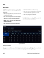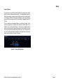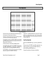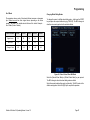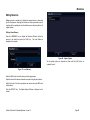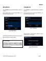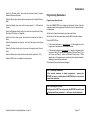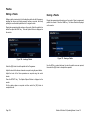
1
& Operating Manual Solution & Solution XL Operating Manual If a portable or temporary three phase mains supply is used to power this desk, we recommend that the desk mains plug is removed before connecting or disconnecting the supply. Serious damage will occur if the desk is connected across two phases. This equipment is designed for use as a lighting control desk only, and is unsuitable for any other purpose. It should only be used by, or under the supervision of, an appropriately qualified or trained person. Zero 88 reserves the right to make changes to the equipment described in this manual without prior notice. E & OE. Federal Communications Commission Document Ref : IM 9210 This equipment has been tested and found to comply with the limits for a Class A digital device, pursuant to part 15 of the FCC rules. These limits are designed to provide reasonable protection against harmful interference when the equipment is operated in a commercial environment. This equipment generates, uses, and can radiate radio frequency energy and, if not installed and used in accordance with the instruction manual, may cause harmful interference to radio communications. Operation of this equipment in a residential area is likely to cause unacceptable interference in which case the user will be required to correct the interference at the operators expense. Issue 1.0 - Software Version 7.3 © Zero 88 2012 Usk House Llantarnam Park Cwmbran NP44 3HD United Kingdom Tel: Fax: e-mail: Web: +44 (0)1633 838088 * +44 (0)1633 867880 [email protected] www.zero88.com * 24 hour answerphone Contents Introduction ..............................................................5 Wide Operation ................................................. 77 Submasters ......................................................... 107 This Manual .........................................................5 Programming ......................................................... 78 Introduction ..................................................... 107 Conventions.........................................................5 Operating Modes ............................................... 78 Submasters Window ....................................... 107 The Solution & Solution XL Lighting Desk ..........5 The Program Window ....................................... 80 Submaster Setup Window .............................. 108 Front Panel Controls ...........................................8 Selecting Fixtures .............................................. 82 Submaster Setup Window .............................. 108 Solution & Solution XL Quick Start Guide ............ 19 Controlling Fixture Parameters ......................... 82 Programming Submasters .............................. 111 Getting Started ................................................. 19 Tagging Parameters .......................................... 83 Editing Submasters ......................................... 112 Selecting Operating Mode ................................ 19 Smart Tagging ................................................... 83 Copying a Submaster ..................................... 115 Controlling Dimmers ......................................... 20 Cue Only Option ................................................ 84 Naming a Submaster ...................................... 115 Programming .................................................... 20 Home Function .................................................. 84 Deleting a Submaster ..................................... 116 Memories .......................................................... 20 Highlight Function ............................................. 84 Playing Back Submasters ............................... 116 Submasters ...................................................... 23 Wheel Editing Modes ........................................ 85 Submaster Flash Functions ............................ 118 Program Window .............................................. 25 Blind Mode ........................................................ 88 Groups ................................................................. 120 Setting Up the Desk ......................................... 25 Clearing the Program Window .......................... 88 Introduction ..................................................... 120 Controlling Fixtures .......................................... 31 Memories ............................................................... 89 Group Window ................................................ 120 Palettes ............................................................. 32 Introduction........................................................ 89 Recording a Group .......................................... 121 Setup..................................................................... 34 The Memories Window ..................................... 91 Naming a Group .............................................. 121 Patch ................................................................ 35 The Memory Setup Window .............................. 92 Copying a Group ............................................. 121 Editing Fixtures ................................................. 38 Programming Memories .................................... 96 Deleting a Group ............................................. 122 Auto Menus ...................................................... 44 Setting Fade and Delay Times .......................... 97 Palettes................................................................ 123 Patch Views ...................................................... 45 Editing Memories .............................................. 99 Introduction ..................................................... 123 Desk Setup ....................................................... 48 Inserting Memories .......................................... 101 Palette Windows ............................................. 123 Files .................................................................. 58 Transferring Memories .................................... 101 Recording a Palette ........................................ 123 Clear Options ................................................... 64 Copying Memories .......................................... 102 Editing a Palette .............................................. 124 Network ............................................................ 65 Naming Memories ........................................... 103 Naming a Palette............................................. 124 Preset Operation ................................................... 75 Deleting Memories .......................................... 103 Copying a Palette ............................................ 125 Two Preset Operation ...................................... 75 Playing Back Memories ................................... 104 Outputting a Palette ........................................ 125 Solution & Solution XL Operating Manual – Issue 1.0 Page 3 Contents Deleting a Palette ........................................... 126 Output Window ................................................ 139 Effects ................................................................. 127 DMX Output Window ....................................... 140 Introduction ..................................................... 127 External Keyboard Mapping ............................ 140 Effects Palette Window .................................. 127 Software Updates ............................................ 141 Effect Window ................................................ 128 Remote ................................................................ 143 Automatic Effects ........................................... 128 Glossary............................................................... 149 Effect Parameters ........................................... 129 Technical Specification ........................................ 152 Effect Parameters on the Wheels .................. 129 Power Supply .................................................. 152 Recording an Effect ........................................ 129 Audio ............................................................... 152 Editing an Effect ............................................. 130 SMPTE (Optional Upgrade) ............................ 152 Naming an Effect ............................................ 130 Video Output ................................................... 152 Copying an Effect ........................................... 131 CAN Port (Optional Upgrade) ......................... 152 Outputting an Effect ........................................ 131 External Storage Devices ................................ 153 Deleting an Effect ........................................... 132 MIDI (Optional Upgrade) ................................. 153 Macros ................................................................ 133 Ethernet ........................................................... 153 Introduction ..................................................... 133 USB Ports ........................................................ 153 The Macro Window ........................................ 133 Mouse .............................................................. 153 Recording a Macro ......................................... 134 External Keyboard ........................................... 153 Setting Up a Macro ......................................... 134 External Floppy Drive ...................................... 153 Naming a Macro ............................................. 135 Touchscreen.................................................... 153 Copying a Macro ............................................ 135 Desk Light (Optional Upgrade)........................ 153 Running a Macro ............................................ 136 DMX Input ....................................................... 154 Deleting a Macro ............................................ 136 DMX Output..................................................... 154 Other Features .................................................... 137 Remote Switches (Optional Upgrade) ............ 154 Monitor Windows ............................................ 137 Supported Touchscreens .................................... 155 Screen Navigation Keys ................................. 138 Index .................................................................... 156 Desktop .......................................................... 139 Page 4 Solution & Solution XL Operating Manual – Issue 1.0 Introduction Introduction Conventions Throughout this manual the following conventions are used: References to front panel controls, buttons and lights appear in capital letters, for example: GRAND MASTER, COLOUR, FIXTURES. Multi Function Keys (MFKs) and soft buttons which appear on the monitor screens are displayed as follows: [Patch], [Desk Setup], [Files], [Clear Options]. The Solution & Solution XL Lighting Desk This Manual A summary of the main functions of the Solution & Solution XL lighting desk is as follows: Control Channels This manual describes the operation of the Solution and Solution XL lighting desks. This chapter contains an overview of the capabilities and controls of the Solution & Solution XL. The Quick Start Guide chapter is designed to get you up and running with the desk, but is not a substitute for the whole manual. For more detail on each function, this manual is divided into chapters, one for each major area of control. Solution & Solution XL Operating Manual – Issue 1.0 The Solution & Solution XL desks have 248 or 296 channels of control as standard. These can be assigned and patched to dimmers and fixtures. The actual configuration is dependent on the desk type. Dimmers The Solution desk has 48 faders which control 24 dimmers (two preset mode) or 48 dimmers (wide mode). The Solution XL desk has 96 faders which control 48 dimmers (two preset mode) or 96 dimmers (wide mode). Page 5 Introduction Fixtures Groups The Solution & Solution XL desks can control up to 200 fixtures. Fixtures can be a simple generic lamp or colour scroller, a moving mirror or moving head (eg Goldenscan, MAC 250), or any other item controllable via a standard DMX signal. The desk provides 400 user definable groups. Automatic groups for each fixture type can be generated from the Setup area, if required. Moving heads, moving mirrors, LED and video systems controlled by DMX are fixtures with multiple parameters. Within the Fixture Library, the Solution & Solution XL is told which channels control which parameters of the fixture. These are then grouped into Position, Colour and Beamshape. Palettes The desk provides 400 user programmable palettes for each of the attributes (Colour, Beamshape and Position). The desk can also generate auto palettes which provide basic colours, gobos and positions based on the fixture types used in the desk. Fixtures can be given a user defined name and number, for ease of reference and may be patched to any of the DMX output channels (1 – 512) on any of the DMX universes (1 – 4). Effects Fixture parameters can be manipulated from within the Program Window, from where they can be added to memories, submasters, palettes or macros. The desk provides 400 user programmable effects. The desk can also generate a number of standard effects which include intensity, colour, beamshape and movement effects. Dimmers are essentially a one channel fixture and as such further dimmers can be patched as fixtures if required. Macros Memories The desk provides 400 user programmable macros. The desk allows you to record memories, for use in the Memory Stack (Playback X). Each memory has a number, name (optional), trigger, a wait time (auto cues) and a set of delay & fade times. Memories may be a Scene or a Chase. Operating Mode Scene – A single set of dimmer and fixture parameter data. Chase – A number of steps, each containing a set of dimmer and fixture parameter data, plus modifiers which determine how the chase runs when played back. The desk has a three seperate operating modes which can be selected for various operators of different skill levels. Lock Functions The desk has a lock function which will prevent misuse of the desk. When the desk is locked with Lock All, it is not possible to perform any operations on the desk. Submasters Audio Input Submasters may be programmed directly with a scene or a chase or they may contain a transferred memory. The Solution desk has 20 pages of 10 submasters. The Solution XL desk has 20 pages of 30 submasters. Page 6 The desk has an audio input, which may be used to trigger chases with bass drives. Solution & Solution XL Operating Manual – Issue 1.0 Introduction SMPTE/MIDI/CAN The desk provides SMPTE, MIDI and CAN connections as an optional upgrade card, which can be used to trigger memories with SMPTE or MIDI timecode triggers, or via ChilliNet. Remote The desk provides an optional remote control interface via six (6) contact closure inputs. These can be added via the optional SMPTE/MIDI/CAN upgrade card. Ethernet The desk has an Ethernet port capable of supporting Art-Net. In addition to Art-Net outputs, this allows smart phones and tablet PCs to be used as remotes. USB Ports The desk has four USB ports, which may be used for saving and loading show files, loading user fixture types and performing software upgrades. The USB ports on the desk support keyboard, mouse, external touch screens, memory sticks, USB CDRW drives, USB floppy disk drives and desk lights. Solution & Solution XL Operating Manual – Issue 1.0 Mouse and External Keyboard The desk provides a USB mouse interface to allow you to move quickly around the monitor screen, select fields, choose options etc. The desk provides a USB interface to a standard PC keyboard, to allow text and numeric data to be entered. Video Output The desk provides the interface for one external monitor display (XGA). It is highly recommended that the desk is operated with a monitor display connected, as important information is displayed here. DMX Output Data is output on DMX channels 1 – 512 on four DMX universes as standard. The DMX output sockets on the rear panel of the desk default to outputting universes 1 to 4. Universes 1 to 4 can also be output via Ethernet using either Art-Net or sACN, see the chapter on Ethernet Options later for further details. Page 7 Introduction Front Panel Controls Master Faders Page Control & Display Multi Function Keys (MFKs) Preset Controls Wheel LCD & Control Wheels Submaster Controls Main LCD Playback X Controls Figure 1 - Solution desk layout This section of the manual describes the various controls and displays on the front panel of the Solution & Solution XL desk. The front panel controls have been divided into the following sections: Preset Controls Other Keys and Controls Page Controls, Mode Keys and Multi Function Keys (MFKs) Main LCD Submaster Controls Wheel LCD and Control Wheels Playback X Controls Page 8 Solution & Solution XL Operating Manual – Issue 1.0 Introduction Preset Controls Preset Faders A and B Master Faders The Solution desk has 48 preset faders arranged as two rows of 24 faders and buttons. These control 24 dimmer channels in two preset mode or 48 dimmer channels in Wide mode. Two Preset Operation – The A MASTER fader controls the maximum output levels from the PRESET A FADERS. The B MASTER fader controls the maximum output levels from the PRESET B FADERS. The Solution XL desk has 96 preset faders arranged as two rows of 48 faders and buttons. These control 48 dimmer channels in two preset mode or 96 dimmer channels in Wide mode. Wide Operation – The A MASTER and B MASTER faders control the maximum output levels from all the PRESET faders or the stored scene according to the setting on the PRESET CONTROL button. Channel Flash Buttons Each desk has a flash button located below each PRESET fader. The CHANNEL FLASH buttons are used to flash, solo or latch the dimmer channels or to select the channels or fixtures assigned to the corresponding faders; their action being determined by the setting of the FLASH MODE button in Special Page 1 of the MFKs. Solution & Solution XL Operating Manual – Issue 1.0 Preset Control Button The PRESET CONTROL button is only applicable in Wide Mode and is used to control which of the A or B MASTER faders has control of the preset faders and which has control over the stored scene. The red LEDs in the button indicate the current state. Pressing the button swaps the function of the two faders. Page 9 Introduction Page Controls, Mode Keys and Multi Function Keys (MFKs) This section of the front panel contains page controls and a seven segment display, a set of Mode keys (FIXTURE, GROUP, COLOUR, BEAMSHAPE, POSITION, EFFECTS, MACRO, SPECIAL) and a block of 20 Multi Function Keys (MFKs). Page Controls and Display The current Page (1-10) is indicated on the dual seven segment display. The PAGE UP and PAGE DOWN keys are used to select the required page. Pressing the PAGE UP and PAGE DOWN keys together selects Page 1. Each mode (Fixture, Group, Colour etc.) has its own current page. Page 10 Mode Keys The mode keys (FIXTURE, GROUP, COLOUR, BEAMSHAPE, POSITION, EFFECTS, MACRO, SPECIAL) determine the function of the block of 20 Multi Function Keys (MFKs). Each of the mode keys contains a red LED, which is lit when selected. If the mode key is flashing, this indicates that the wheels are in control of this attribute but the MFKs are showing another function. This allows simultaneous selection of fixtures whilst still manipulating attributes, for example. Solution & Solution XL Operating Manual – Issue 1.0 Introduction The function of the Mode keys is summarised below: Multi Function Keys (MFKs) FIXTURE – turns the block of 20 MFK‟s into Fixture selection buttons. GROUP – turns the block of 20 MFK‟s into Group selection buttons. COLOUR – turns the block of 20 MFK‟s into Colour Palette selection buttons. BEAMSHAPE – turns the block of 20 MFK‟s into Beamshape Palette selection buttons. Pressing and releasing one of the Mode Keys changes the MFK‟s to that page and the control wheels follow (when appropriate). The MFKs remain in that mode until a different Mode key is pressed. POSITION – turns the block of 20 MFK‟s into Position Palette selection buttons. Pressing and holding down a Mode key temporarily changes all the MFKs to that function. Selecting an MFK will apply that MFK but the MFKs will return to the previous MFK mode, when the Mode key is released. EFFECTS – turns the block of 20 MFK‟s into Effect Palette selection buttons. MACRO – turns the block of 20 MFK‟s into Macro selection buttons. SPECIAL – turns the block of 20 MFK‟s into Special function keys. Solution & Solution XL Operating Manual – Issue 1.0 The Multi Function Keys are arranged in 4 rows of 5 keys with a graphical LCD above each row of keys. The brightness and contrast of the LCDs can be adjusted as required. Each Multi Function Key contains a red LED. These LEDs are used to indicate which fixtures, groups etc. are selected depending on their current function. For example – Press and release the FIXTURES key. The MFKs change to fixture selection keys. Select a number of fixtures. Press and hold down the COLOUR key. The MFKs change to colour palette selection keys (while the COLOUR key is being held down). Press one of the colour palette MFKs to apply the colour palette to the selected fixtures. Release the COLOUR key and the MFKs return to being fixture selection keys. Page 11 Introduction Multi Function Key LCDs The LCDs above the MFKs typically display three lines of data. Example 1 - When the MFKs are assigned to colour palettes - The first line shows the number of the palette and the data stored. The second (and third if required) lines show the palette name. Page 12 Example 2 - When the MFKs are assigned to fixtures – The top line shows the fixture number. The second and third lines show the fixture name, eg Mac 300 : Mode 4. Solution & Solution XL Operating Manual – Issue 1.0 Introduction Submaster Controls Submaster Faders The Submaster faders are used to output channel data (scenes) or chases. The fader controls the output level of the intensity channels and triggers the LTP channels in the programmed data. Submaster Page Controls and Display The current Submaster Page (1-20) is indicated on the dual seven segment display. The PAGE UP and PAGE DOWN keys are used to select the required submaster page. Submaster Flash Buttons The Submaster flash buttons, located below each of the submaster faders are used to flash, solo or latch the data programmed on the submaster. The action of these buttons is user definable via the Submaster Setup Window (accessible by holding SETUP and pressing SUBMASTERS). These buttons are also used to select submasters when in the Submaster Window. Solution & Solution XL Operating Manual – Issue 1.0 Pressing the PAGE UP and PAGE DOWN keys together selects submaster Page 1. Submaster Step Button The Submaster STEP button is used to manually step through any chases with manual drive being output on the submasters, or to initiate Beat tempo matching. Page 13 Introduction Playback X Controls Playback X (Memory) Master Fader The MASTER fader controls the maximum output level of the memory being output on the Playback X. This fader only affects the dimmer and brightness fixture channels (if applicable). The Colour, Beamshape and Position fixture channels are not affected by the master fader. Go Button The GO button is used to initiate a crossfade between the memory currently being output and the Next memory in the memory stack as indicated on the Memories screen. Pause Button The PAUSE button is used to pause a crossfade between the current and next memories. When a crossfade has been paused, the red light in the button flashes. Pressing the GO button releases the pause. Pressing Pause again will step backwards in the cue stack. Override Control The OVERRIDE control is used to slow down or speed up the crossfade between the current and next memory. When the control is moved away from the central neutral position, this is indicated on the monitor screen. Step Button The STEP button is used to manually step through any chase memory with manual drive currently being output on the Playback X. Page 14 Solution & Solution XL Operating Manual – Issue 1.0 Introduction Main LCD The Main LCD provides part of the user interface on the front panel of the desk. The content, layout, operation and other information displayed on this screen is dependent on the current operation being carried out on the desk. In Setup, the Main LCD acts as a guide showing where you are in the Setup menu structure and gives instructions on what to do. When the Memories or Submasters screen are selected, the Main LCD acts as a small viewing portal on the Memories or Submasters window. When any of the other main windows (Program Window, Outputs, Groups etc.) are selected, the Main LCD displays a simple text message directing you to refer to the monitor, plus the desk software version and other helpful information, for example: Output Window See Monitor for details For help press SHIFT & LEFT & RIGHT support.zero88.com Solution & Solution XL Operating Manual – Issue 1.0 Page 15 Introduction Other Keys and Controls Main LCD SETUP - used to enter Setup mode and display the Setup screen on the Main LCD and monitor. Also used for exiting Setup mode. MEMORIES - used to display the Memories screen on the Main LCD and monitor. SUBMASTERS - used to display the Submasters screen on the Main LCD and monitor. OUTPUTS - used to display the Outputs screen on the monitor. PGM WIN - used to display the Program Window (programmer) on the monitor. Cursor Keys (UP, DOWN LEFT, RIGHT) - used to move around the fields on the main LCD (where appropriate) and/or the monitor screen. These buttons are equivalent to the four cursor keys on an external keyboard (if fitted). Plus (+) and Minus (-) - used to increment or decrement the value of the current selection. TIME - used as a shortcut for moving the cursor to the various fade fields on the Memories and Submasters screens. It is also used in combination with other keys to perform various functions over the internal fade time (eg outputting palettes over a time). LOAD - used for loading items such as memories, submasters or palettes into the Program Window for editing. CLEAR - used for clearing the Program Window. As soon as any changes are made to the look in the Program Window, the LED in the CLEAR key is lit, to indicate that dimmer or fixture parameter values have changed. Pressing the CLEAR key once will clear (undo) all the operations made in the Program Window since the LED was first lit, except for the fixture selection. The LED in the key goes out. Pressing the CLEAR key a second time clears the fixture selection in the Program Window. UPDATE - used to update loaded items or items modified in the Program Window. NAME - used for naming memories, submasters, palettes etc. Page 16 Solution & Solution XL Operating Manual – Issue 1.0 Introduction RECORD - used for programming memories and submasters. COPY - used to copy items from one location to another (eg memories, submasters, groups, palettes etc.) Holding down SHIFT and pressing COPY is used to transfer a memory onto a submaster. INSERT - used to insert point memories, add or insert chase steps or add or insert duplicates when patching dimmers and fixtures. DELETE - used when deleting items (memories, submasters, groups, palettes etc.) ENTER - used for completing commands and selecting „soft‟ buttons on the Main LCD, monitor screens and popup windows. Solution & Solution XL Operating Manual – Issue 1.0 HOME - used as a quick method for setting all the parameters, or all the parameters for a particular attribute to their home values. The Home values are found in the Edit Fixtures table in Setup and can be adjusted as required. GRAND MASTER - controls the final output values of all dimmer and fixture intensity channels, resulting from the Program Window, Playback X and submasters. The Grand Master level is displayed on the monitor screen. BLACKOUT - reduces the outputs of all dimmer and fixture intensity channels to zero. Pressing the BLACKOUT key toggles between active and not active. The red LED in the BLACKOUT key flashes when blackout is active. SHIFT - used in conjunction with various front panel controls to provide additional functions, eg holding SHIFT and pressing the COLOUR key displays the Colour Palette Window on the monitor. Page 17 Introduction Wheel LD and Control Wheels Wheel LCD The Wheel LCD is used to indicate which fixture parameters or other data are being controlled by each of the three control wheels. Example - When showing fixture parameter values - The Wheel LCD displays the parameter name (eg Colour1) and the value in %, DMX or the parameter detail name. Wheel Editing Modes There are a number of wheel editing modes which apply when editing several fixtures at the same time (Absolute, Relative, Fan First, Fan Middle, Fan Last, Fan V). Tag status is shown by inverse graphics – a white background shows a tagged parameter, and a blue background display shows an untagged parameter. For each attribute there is a normal wheel mode which applies when the control wheel is moved and a shifted wheel mode which applies when the SHIFT key is held down and the control wheel is moved. Control Wheels For further details on each of the wheel editing modes, and how to adjust the normal and shifted mode for each attribute – see page 85 of the manual for full details. The three control wheels are used for setting fixture parameter levels and other data. The names of the fixture parameters or other data currently assigned to each of the wheels and their values is shown on the Wheel LCD. Page 18 Solution & Solution XL Operating Manual – Issue 1.0 Quick Start Guide Solution & Solution XL Quick Start Guide Welcome to the Solution & Solution XL Quick Start Guide. This chapter is intended to get you started using your new desk – for full information, please see the relevant chapters of this User Manual. Getting Started Before you power up the desk, it is essential to attach all the peripherals you will be using. The desk has support for USB peripherals such as a Keyboard and Mouse and a VGA monitor (or touch screen). In addition, you should connect the DMX or Ethernet cables for controlling your lighting rig. These must be connected before powering up, as subsequent connection could result in software or hardware malfunctions. Once you have connected all the peripherals you require, turn on the desk using the switch on the rear panel. If you see no immediate response, check that the power switch is set to ON, and that the IEC lead is firmly attached to the external power supply. The desk will boot up and you will be presented with the desk software. Selecting Operating Mode There are three operating modes for the Solution & Solution XL desks. These operating modes are designed for operators with different skill levels to ensure they get the maximum out of the console. The first time you power on the desk, it will prompt you to select an operating mode. For the purposes of this Quick Start Guide, we will select Non Tracking Mode. In this mode, everything that is output from the desk is recorded into each cue, and changes made in one cue will not affect other cues. As you progress your knowledge of the Solution & Solution XL you may want to experiment with the other modes. Details of these modes can be found in the user manual, page 78 for full details. Solution & Solution XL Operating Manual – Issue 1.0 Figure 2 - Select Operating Mode Page 19 Quick Start Guide Controlling Dimmers The default setup for the desk gives you control of dimmers 1 to 48 (DMX addresses 1 to 48 on Universe 1) on the generic preset faders 1 to 48 (1 to 96 on the Solution XL). This can be defined differently, but for now we will assume you‟re working with the default settings. Check that the GRAND MASTER fader is at the top (100%) and that the A and B MASTER faders are also at the top. The LED in the PRESET CONTROL button should be lit in “A Faders B Stored”, indicating that the A MASTER is controlling the level of the Preset Faders. Moving the Preset Faders will bring their channels on, and you will see the result on stage. You will also see the results in the Program Window (see later in this guide). You can bring the A MASTER fader down at any time to inhibit the level of the Preset faders. Programming Once you have set up a scene that you like you can then record that state into a memory, or a submaster. Memories are played back sequentially in a theatre style (Cue 1 GO, Cue 2 GO, etc). Submasters are mixed together by raising the faders, useful for live events or unpredictable shows. Memories Recording a Memory If you aren‟t already in the Memories Window, press the MEMORIES key. This will bring the Memories Window up onto the monitor, and Memory 1* will be highlighted as the “Next” memory. As a rule any changes you are making on the monitor or LCD will happen to the highlighted “Next” memory, so follow the yellow bar on the monitor – the green bar simply shows the current memory. To store the memory, simply press the RECORD key. The 1* will change to a 1 (the * indicates that the memory is unprogrammed) and fade times will appear for the parameters you have recorded. The Next memory automatically increases to select another memory. Subsequent memories can then be set up and recorded using the same method. Adjusting Fade and Delay Times By default, a memory will receive a 3 second fade time on the intensity parameters (dimmers) and a 0 second fade time on all moving light attributes (colour wheels, gobo wheels, etc). These are displayed in the Memories Window in the relevant columns. Note that only one of Colour, Beamshape and Position times are shown at any one time – press the relevant key to switch the monitor to displaying these times. The fade and delay times can be adjusted by moving the cursor to the required field in the Memories Window and using the control wheels, or by moving to the field on the Memories Window, pressing the ENTER key, typing in the time using the MFKs and pressing ENTER to confirm. See the Memories chapter in the User Manual for full details of adjusting times. Editing Memories You can make changes to a memory by loading it back into the Program Window. To do this, press the MEMORIES key to display the Memories Window. Select the memory to be edited, then press the LOAD key. The Load Options Window is displayed on the monitor: Now select the memory number to be programmed, if different to the one already selected. This can be done using the + and – keys, or by pressing ENTER then using the MFKs to enter a numeric value. Page 20 Solution & Solution XL Operating Manual – Issue 1.0 Quick Start Guide Use the MFKs to enter the memory name as required, then select the [OK] button to complete the operation. Playing Back Memories Figure 3 - Load Memories Window Select the [OK] button to load the memory into the Program Window. The levels from this memory will be output. Now you can make changes using the preset faders and fixture controls, and press the UPDATE key. The Update Options Window is displayed on the monitor. Select the [OK] button to complete the edit. Before playing back the programmed memories in the stack, it is important to clear the Program Window by pressing the CLEAR button. This removes any unrecorded commands and sends fixtures to their default values (assuming no Submasters are outputting). The Playback X controls on the front panel together with the Memories Window are used to play back the programmed memories in the memory stack. Naming Memories Each memory can have a name associated with it. These are displayed in the memories window and can be useful for reminding you of the contents of a particular memory. To set the name, press the MEMORIES key to display the Memories Window. Select a programmed memory to be named. Press the NAME key. The Name Window is displayed on the monitor: Starting the Show Set the Playback X MASTER and GRAND MASTER faders to full. Ensure that Blackout is not active. Check that the OVERRIDE control is in it‟s central position. Select the first programmed memory using the arrow keys and press the GO button. The memory fades up according to it‟s programmed fade and delay times. Figure 4 - Name Memories Window Solution & Solution XL Operating Manual – Issue 1.0 Page 21 Quick Start Guide Selecting the Next Memory After a cue is run, the selected (highlighted in yellow) memory will automatically move on to select the next programmed memory. To select a different memory to be output next – move the cursor to the Next memory number field, then use the + and – keys or the UP and DOWN arrow keys to select the next memory to be output. The Next memory to be output is highlighted by a yellow bar. Using the GO Button When a memory is triggered by the GO button, the Intensity, Colour, Beamshape and Position fades will occur in the times programmed. If necessary, all fades may be controlled by the OVERRIDE and PAUSE controls on the front panel. To resume a paused fade, press the GO button. Page 22 Solution & Solution XL Operating Manual – Issue 1.0 Quick Start Guide Submasters Once you have set up a scene (or part of a scene) that you like you can then record that onto a submaster. Recording a Submaster Press the SUBMASTERS key to display the Submasters Window, then select the submaster number to be programmed by pressing the relevant flash button under the submaster. Note that there are 20 pages of submasters available so check the page indicator is on 1 before continuing. To store the Submaster, simply press the RECORD key. The Submaster LCD will indicate that a scene is stored onto the submaster. Adjusting Fade Times Editing Submasters The easiest way to Edit a submaster is simply to use the Update function. With the submaster active, make the changes you require using the preset faders and fixture controls, then press Update. The MFKs will list all of the currently active submasters and memories which can be updated, as well as any palettes. Select the Submaster to update, and press OK. Clear the programmer and the update is complete. Naming Submasters A submasters name is displayed on the LCD above it. To set the name, press the SUBMASTERS key to display the Submasters Window, then select a programmed submaster to be named. Press the NAME key and the Name Window is displayed on the monitor: Default fade times for Intensity, Colour, Beamshape and Position are defined in Desk Setup, and can be adjusted if required via the Submasters Window. The fade times can be adjusted by moving the cursor to the required field in the Submasters Window and using the control wheels, or by moving to the field on the Submasters Window, pressing the ENTER key, typing in the time using the MFKs or external keyboard and pressing ENTER. See the Submasters chapter in the User Manual for full details. Figure 5 - Name Submasters Window You can now use the MFKs to enter the submaster name as required and press [OK] to complete the operation. The name will be displayed on the Submaster LCD, above the fader. Solution & Solution XL Operating Manual – Issue 1.0 Page 23 Quick Start Guide Playing Back Submasters Before playing back submasters, it is important to clear the Program Window by pressing the CLEAR button. This prevents any unprogrammed data from affecting the outuput of the submasters. Raising a submaster fader will bring the data programmed on the submaster to the outputs. For attributes, the submaster will trigger at 5% a crossfade to the new values. For dimmers, the submaster fader provides intensity control. Page Overlay on Submasters It is possible to output scene or chase data from several submasters on different pages at the same time provided that they are not controlled by the same physical fader. If the submaster page is changed while any of the submaster faders are up, or any of the SUBMASTER FLASH buttons are being held down, the fader and button remains in control of the original data and the outputs for the original submaster are held. The new scene, chase or transferred memory associated with the fader or button is not made available until the fader is brought back down to zero or the flash button is released. Page 24 Solution & Solution XL Operating Manual – Issue 1.0 Quick Start Guide Program Window Setting Up the Desk The Program Window is central to the programming functionality on the Solution & Solution XL desk. It is recommended (but not mandatory) that the Program Window is displayed on the monitor screen when setting up memories, submasters or palettes. Now you‟ve grasped the basics of the desk, it‟s time to venture into the Setup area of the desk. Setup is used for all of the major functions on the desk, such as clearing out the current show, loading in a new one, or adding moving lights to your show. To display the Program Window on the monitor press the PGM WIN key. As you adjust dimmer levels, select fixtures and adjust their parameters with the control wheels, or by other methods, the corresponding information is shown in the Program Window. To get into Setup, press the SETUP key. The Setup Window is displayed on the monitor screen with the Patch option selected as default : The dimmer and fixture parameter data displayed in the Program Window can then be recorded to memories, submasters or palettes as required. The top part of the Program Window shows the dimmer channels. Tagged dimmer channels are shown in red text, untagged dimmer channels in white text. The currently selected fixtures are highlighted in yellow. Fixture parameters which are tagged have a light blue background, those that are untagged have a dark background. Figure 6 - Program Window Solution & Solution XL Operating Manual – Issue 1.0 Figure 7 – Setup mode, Patch Screen Page 25 Quick Start Guide Setup gives you access to the core settings for the desk such as the patch, default fade times and output settings. As such you shouldn't normally need to enter the Setup area during a show. It is, however also used for saving and loading of show files and updating the desk software, so you should be familiar with it even if you are only using generic lights. The MFKs and monitor then display a list of fixture types for that manufacturer. Note that some manufacturers fixtures are spread over multiple pages, and you may need to use the Page function to find the fixtures you are using. Select the required fixture type (eg MAC 301 WASH) using the MFKs, and then select the Mode (eg Mode 4). Adding and Patching Fixtures Once in Setup, you can patch in your moving lights. Moving Lights need to be set up on the desk as the desk doesn‟t automatically know what you are using. The following operations may be be performed using the MFKs on the front panel or via the popup windows on the monitor or a combination of the two methods, as preferred. You need three pieces of information about your moving lights before you start the process which are: The fixture manufacturer and model number - these are generally found on the light itself. The mode you wish to operate the moving light in. This has to be set on the moving light itself, and match on the desk – check the user manual of the light for full details. The DMX address of the light. This is basically the lights identifying information within your lighting system, and must be unique for each light you wish to control. Moving lights generally take up a number of channels, sometimes as many as 30, so consult the moving lights manual before setting the DMX address. Figure 8 - Patch Wizard Setting the DMX Start Address Once you have this information you are ready to set up your fixtures… Once you have selected the required fixture type (eg MARTIN MAC 301 WASH : 16 Bit), you can set the DMX start address for the fixture(s): Selecting a Fixture – Manufacturer, Fixture Type and Mode Select the DMX universe (1-4) and enter the required start address using the MFKs or directly into the field on the popup window on the monitor. Ensure you are in Setup mode, and that the Setup LED is lit. Now press the [Add Fixtures] MFK. Select the first letter of the fixture manufacturer (eg M) and then the manufacturer (eg MARTIN) using the MFKs. Page 26 To patch to the next available address in the selected universe use the [Next Address] MFK or soft button on the window. Press ENTER to confirm. Solution & Solution XL Operating Manual – Issue 1.0 Quick Start Guide Assigning Fixture Type to MFKs Having selected the required fixture type and specified a DMX start address, you now tell the desk where you would like these fixtures to be. Press the MFK for the fixture you require – the LCD above it will change to show the fixture assigned to the MFK and the DMX address for this fixture. There are 10 pages of 20 fixtures available. When you have assigned the fixture type to the required fixture selection key(s), press ENTER to return to the Patch options. Note – Fixture Types The complete Zero 88 Fixture Library is stored on the desk, but it is also possible to load additional fixture types from memory stick. If the fixture type you require is not in the fixture library on the desk you can import the fixture type – see Setup chapter of the User Manual for full details. Auto Menus The desk can generate automatic groups, palettes and macros based on the different fixture types that have been assigned. To generate any or all of these items, press the [Auto Menus] MFK, then press [Create Auto Groups], [Create Auto Palettes] or [Create Auto Macros] MFK. For further details see the Setup chapter of the manual. Solution & Solution XL Operating Manual – Issue 1.0 Page 27 Quick Start Guide Desk Setup Displays – Adjust the brightness and contrast of the Main LCD and other LCDs on the front panel; calibration of external touch screen monitor; screen timeout. Peripheral - Allow mouse or trackball to control pan and tilt parameters; adjust control wheel sensitivity. Inputs – Set up SMPTE and MIDI Timecode; Set CAN mode; MIDI Notes; Configure Remote Switches. Outputs – Map DMX universe to the physical DMX outputs on the desk. Behaviour – Confirm Overwrites; Recovery Mode; Preset Mixing; Keep Parameters Separate options. Memory Defaults – Set up the default delay and fade times for each attribute (Intensity, Colour, Beamshape, Position); Move on Dark parameters. Submaster Defaults – Set up default options for flash button action, trigger level and attribute fade times. Set Date – Set the date on the desk. Set Time – Set the time on the desk. Figure 9 - Desk Setup The Desk Setup function allows you to configure or customise the settings on the desk to your own requirements. Desk Setup is divided into a number of different sections which are accessed by pressing the corresponding MFK or soft button on the monitor. A summary of the Desk Setup options are provided below. For full details of the various options refer to the Setup chapter in the User Manual. Page 28 Solution & Solution XL Operating Manual – Issue 1.0 Quick Start Guide Saving Shows Loading Shows The Solution & Solution XL saves the show automatically to its internal memory at regular intervals. External backups of the show data can be made to a USB Storage Device (eg memory stick). Note: Loading a show file will clear any existing show data from the desk so ensure that you have backed up your previous show before you load another one onto the desk. Connect your storage device to one of the USB ports on the desk. Press the [Files] MFK or select the [Files] button on the Setup Window. Press the [Save Show] MFK or select the [Save Show] button on the monitor. The Save Show window is displayed on the monitor. Select the required Destination Device, by pressing the relevant MFK. If you do not see your device immediately, press Refresh. Now you can enter a name for the show file, using the MFKs like a mobile phone text message. You can also use the on-screen keyboard at this point, or a USB keyboard, if required. This name will be used as the file name on the destination device, so ensure it is unique and easily identifiable. Once you have entered the name, press ENTER, then press the [OK] MFK to save the show. Figure 11 - Loading a show To load a show, connect the storage media to a USB port on the desk. Press the [Files] MFK, then press the [Load Show] MFK The Load Show window is displayed on the monitor. Select the required source device, using the MFKs. A list of show files found on the selected device is displayed in the window (this may require you to use the Page Function to locate your show, if a lot of files are found on the disk). Select the required show file from the list, then press the [OK] button to load the show. Figure 10 - Saving a Show Solution & Solution XL Operating Manual – Issue 1.0 Page 29 Quick Start Guide Clear Options This section of Setup allows you to clear (delete) various components which make up the show file (memories, submasters, groups, palettes etc.) There is also a Reset Desk option which clears the show completely, resets the desk and returns the setup parameters and DMX patch to the factory defaults. Figure 12 - Clear Options Exiting Setup Once you have finished making changes to the setup, press the SETUP key to exit setup. Page 30 Solution & Solution XL Operating Manual – Issue 1.0 Quick Start Guide Controlling Fixtures Once you have added your fixtures to the desk, you are ready to start controlling them. Selecting Fixtures Press the FIXTURES key. The MFKs become fixture selection buttons and the LCDs above the keys indicate what fixture has been assigned to which MFK. Press the MFK to select the fixture; press it again to deselect the fixture. Note that you can multi-select fixtures by holding the first fixture button down whilst tapping the last fixture button (all intermediate fixtures will be selected). Homing Fixtures The easiest way to see which fixtures in the rig you are controlling is to „home‟ them. This sets their parameter values to the Home values defined in the Edit Fixtures table in Setup. Typically these are position (Pan and Tilt) to 50%, the dimmer to 100% with an open white beam (shutter open, no gobos or effects). With your fixtures selected, press the HOME key. This sends all the parameters of the selected fixture(s) to their home values and automatically tags the fixture parameters. Controlling Fixture Parameters Each fixture type has it‟s own set of parameters (intensity, color, gobo, pan, tilt etc.) which are classified or grouped together into different attributes (Colour, Beamshape and Position). Once a fixture has been selected, the attribute buttons and control wheels can be used to adjust the parameter output levels as required. Controlling Intensity The Intensity parameter of a fixture is adjusted by a control wheel. First select the fixture(s) required as described above and then press the POSITION key (if not already selected). The intensity parameter is assigned to the third wheel. Use the control wheel to adjust the intensity level as required. The Solution & Solution XL Operating Manual – Issue 1.0 output value is shown on the Wheel LCD above the corresponding control wheel. Tip – No Intensity Output ? If the intensity output levels do not change when you adjust the intensity parameter using the wheel, check that the GRAND MASTER fader is at full and the BLACKOUT button is off. If the selected fixture(s) have a Shutter parameter, check that the shutter is open. Controlling Colour, Beamshape and Position Parameters The colour, beamshape and position parameters of the selected fixture(s) are controlled using the control wheels. First select the required fixture(s) and then press one of the attribute keys (COLOUR, BEAMSHAPE or POSITION). The corresponding parameters for the fixture(s) are assigned to the control wheels and are indicated on the Wheel LCD. If the fixture has more than three controllable parameters for the selected attribute, press the attribute key again to select the next group of parameters. Tagging Parameters On the Solution & Solution XL desk fixture parameters must be „tagged‟ for them to be recorded. The tag status of each fixture parameter is indicated on the Wheel LCD (inverse video indicates tagged) and in the Program Window by it‟s background colour (green indicates tagged). If a parameter‟s value is changed by moving the control wheel, homing the fixture, applying a palette or directly in the Program Window, it will be tagged automatically. It is possible to tag and untag fixture parameters manually by holding down the CLEAR key and moving the corresponding control wheel or fader. Page 31 Quick Start Guide Palettes Recording Palettes The Solution & Solution XL desk provides four sets of 400 palettes. The palettes are stored under the headings of Colour, Beamshape, Position and Effects. When an attribute has been selected last (eg Colour key was pressed and the wheels are showing Cyan, Magenta and Yellow parameters), the MFKs display the Colour palettes. Programming a palette is simple. Set up the fixture outputs as required, ensuring that the correct parameters are tagged. Press the COLOUR, BEAMSHAPE or POSITION key to make the MFKs palette selection keys. To store the palette, press and hold down the corresponding palette MFK for two seconds. The LED in the palette MFK is lit when the palette has been recorded. Palette Windows Note – Recording Palettes Each set of palettes has it‟s own palette window. To display a palette window on the monitor, hold down the SHIFT key and then press the appropriate attribute key (COLOUR, BEAMSHAPE, POSITION or EFFECTS). The palette window contains a soft button for each of the palettes. Only the tagged fixture parameters of the selected attribute (eg Colour) are recorded into the palette. Naming a Palette Palettes can have a name, which is displayed on the LCD and in the Palette window. To set the name, display the appropriate palette window on the monitor. Select a programmed palette to be named. Press the NAME key. The Name Window is displayed on the monitor: Figure 14 - Naming a Palette Use the MFKs or external keyboard to enter the palette name as required, then select the [OK] button to complete the operation. Outputting a Palette Figure 13 - Palette Window Page 32 Select the required fixture(s). Press the COLOUR, BEAMSHAPE or POSITION key to make the MFKs Palette Selection Keys. Use the PAGE UP or PAGE DOWN key to select the required page, if necessary. To output the palette, press the Palette MFK and the data will be output for the selected fixture(s). Solution & Solution XL Operating Manual – Issue 1.0 Quick Start Guide Note – Outputting a Palette over Time Holding down the TIME key and pressing a palette MFK will crossfade to the palette output values in the internal Fade Time. The internal Fade Time can be found and adjusted on Special Page 1 of the MFKs. Solution & Solution XL Operating Manual – Issue 1.0 Page 33 Setup Setup In Setup the desk provides functions for setting up the desk - assigning, patching and editing fixtures, saving and loading shows, clearing show data, resetting the desk etc. Press the SETUP key to display the Setup options on the MFKs and the Setup Window on the monitor. The following Setup options are displayed: Patch Desk Setup Files Clear Options Network On entering Setup, the Patch option is selected automatically and the corresponding soft buttons are displayed on the monitor and MFKs. The Setup Window on the monitor shows the current patch information, as shown in the following example: Figure 15 - Setup Screen To select any of the other Setup options (Desk Setup, Files etc.) press the corresponding MFK or click on the corresponding button in the Setup Window on the monitor. To exit Setup, press the SETUP key on the front panel. Page 34 Solution & Solution XL Operating Manual – Issue 1.0 Setup Patch The Patch option allows you to assign fixture types to the fixture selection buttons, patch them to the DMX outputs, adjust parameter default, home and topset values, adjust fixture alignment values (pan/tilt reverse and swap) and a number of other associated functions. The complete Zero 88 Fixture Library is stored on the desk, but it is also possible to load additional fixture types from a memory stick. Adding fixtures may be performed using the MFKs on the front panel or via the popup windows on the monitor or a combination of the two methods, as preferred. DMX Patching There are three pieces of information you need to know about a moving light before it can be patched to the lighting desk. These are: The fixtures manufacturer and model number – these are normally printed on the side of the light The „mode‟ of the fixture. This is usually set in the menu structure of the fixture but can also be set by DIP switches. For details on the modes, check the user manual for the fixtures themselves. The DMX address you wish your fixtures to be at. The DMX address is the start address where the fixture will be located. Each fixture takes a different number of channels, sometimes as many as 30. If a fixture starts at DMX address 100 and uses 16 channels, the next fixture should be set at 115. Again the DMX address is usually set in the menu structure of the moving light, although it can be set by DIP switches on older equipment. Once you have these three pieces of information you are ready to add the fixtures to the desk. Figure 16 - Patch Screen (Setup) Add Fixtures This option allows you to add fixtures to the fixture schedule, assign the fixtures to the fixture selection buttons (MFKs) and optionally patch them to DMX output addresses. Solution & Solution XL Operating Manual – Issue 1.0 Page 35 Setup Selecting a Fixture – Manufacturer, Fixture Type and Mode Press [Add Fixtures], then select the first letter for the required manufacturer (eg M) then the manufacturer (eg MARTIN) using the MFKs or directly from the list on the popup window on the monitor. Select the required fixture type (eg MAC 500) using the MFKs or directly from the list on the popup window on the monitor: Figure 18 - Fixture Type Selection Figure 17 - Manufacturer Selection The MFKs and monitor then displays a list of fixture types for that manufacturer. Some manufacturers have more than 20 fixture types, in which case the MFKs will need to be paged in order to select the fixture you require. The Page Up/Down buttons are used to select the required page. Page 36 If there are several operating modes for the selected fixture type these are displayed on the MFKs and monitor screen. Select the required mode (eg Mode 4) and the desk will load the fixture profile, ready for patching. Solution & Solution XL Operating Manual – Issue 1.0 Setup Setting the DMX Start Address Once you have selected the required fixture type (eg MARTIN MAC 500 Mode 4), you then have the option of selecting the DMX start address for the fixture(s): Assigning Fixture Type to MFKs Having selected the required fixture type specified a DMX start address, you can now assign your fixtures to the Fixture MFKs. There are 10 pages of 20 MFKs available, giving a total of 200 fixtures patchable. First use the PAGE UP or PAGE DOWN keys to select the required page of MFKs, then press an MFK to assign the fixture type to that key. The LED in the MFK is lit to indicate that the key is now assigned. The fixture type and DMX address is displayed in the LCD above the MFK. Repeat this process for each fixture to be assigned. Press the same MFK again to remove the fixture type assigned to that key. When you have assigned the fixture type to the required fixture selection key(s), press ENTER to return to the Patch options. Notes – Assigning Fixture Types to MFKs Several MFKs may be assigned at the same time by holding down the first MFK in the required range and then pressing the last MFK in the range, eg hold down MFK 1 and press MFK 10 – the selected fixture type is assigned to MFKs 1-10 inclusive. Figure 19 - Assigning a DMX Address The desk has 4 DMX universes available for patching, so the first thing you need to do is to select the DMX universe (1 to 4) you wish to work on. Next enter the required start address using the MFKs or directly into the field on the popup window on the monitor. To patch to the next available address in the selected universe use the [Next Address] button. Once you have set the DMX address required, press the ENTER button to confirm. Solution & Solution XL Operating Manual – Issue 1.0 Page 37 Setup Editing Fixtures The Edit Fixtures screen allows you to customise a number of different parameters for the fixtures in the fixture schedule. These functions are summarised below: Default – These settings edit the fixture parameter default values which are output when a fixture is released. Home – Home Values are applied when a fixture is homed or highlighted. Topset – Allows you to set upper limits for fixture parameter values. Alignment – Used for Inverting Pan, Tilt and Swapping Pan and Tilt parameters for individual fixtures. Name – Provide user defined fixture names for the assigned fixtures Number – User defined fixture numbers for easy referencing. Patch – Patch, repatch or unpatch fixtures. Move fixture location to MFK, Preset Fader or DMX In channel, swap one fixture type for another. Delete – Delete (unassign) fixtures from the schedule. Press the [Edit Fixtures] button to load the Edit Fixtures window to the monitor. Note that you require a monitor to edit fixtures: Figure 20 - Edit Fixtures Selecting Fixtures to be Edited Before carrying out any of the edit fixture operations - Select the fixture(s) to be edited using the fixture selection keys (MFKs). As each fixture is selected it is added to the Edit Fixtures screen on the monitor. Fixtures can be removed from this selection by pressing their fixture selection key (MFK) at any time. Page 38 Solution & Solution XL Operating Manual – Issue 1.0 Setup Editing Default / Home / Topset Values Press the [Default] or [Home] or [Topset] button as required on the monitor (if not already selected). Use the cursor keys to move the cursor to the individual field to edit or use the ALL row to edit the value for all of the selected fixtures. Select the Yes or No option as required and press ENTER. Once all changes have been made, press the [OK] key to return to the Patch screen. Editing the Fixture Name or Number Select the required field, press ENTER, enter the required value and press ENTER. Fixture Names and Numbers can be altered from any of the tabs, simply use the cursor keys to move the cursor to the Name or Number (No) field for the selected fixture. Once all changes have been made, press the [OK] key to return to the Patch screen. Press ENTER, enter the required fixture name or number and press ENTER. If you make a mistake in Edit Fixtures, or simply wish to revert to the original values from the fixture library then press the [Reset All] key. If you wish to cancel all editing of the fixtures, press the [Cancel] key. Once all changes have been made, press the [OK] key to return to the Patch screen. Patching Functions Editing Alignment Press the [Alignment] button on the monitor. Use the cursor keys to move the cursor to the individual field to edit or use the ALL row to edit the value for all the selected fixtures. The Patch option in Edit Fixtures provides a simple and clear way to patch or repatch fixtures, add duplicates, unpatch fixtures and move the location of fixtures, if required. The 48 or 96 dimmers on the Solution and Solution XL desks respectively default to being patched to DMX addresses 1 – 48 or 1 – 96 on universe 1. In addition to specifying a DMX start address when assigning fixture types, the desk provides functions that allow you to patch or repatch individual fixtures or groups of fixtures to DMX output addresses on any of the DMX universes. It is also possible to patch a fixture to more than one DMX address in one or more universes. These additional patch addresses are known as duplicates. Select the fixture(s) to be edited. Click on the [Patch] button in the Edit Fixtures Window. Figure 21 - Editing Alignment Select the required field and press ENTER. Solution & Solution XL Operating Manual – Issue 1.0 Page 39 Setup Select the Universe by clicking on the [Universe] button and selecting the universe from the drop down menu. Enter the required DMX address in the Address field provided or press the [Next Address] button to automatically pick up the next available patch address in the selected universe. Press the [OK] button to complete the patching operation or the [CANCEL] button to cancel. Figure 22 - Editing Patch The patch table shows the Location (MFK, Preset Fader or DMX In), DMX-In assignment and DMX address(es) that each of the selected fixtures are currently patched to. If a fixture has not been patched to the DMX output then the corresponding DMX column will show „Add‟ Patching Fixtures Move the cursor to the DMX column for the required fixture and press the ENTER key. The Patch Fixture popup window is displayed on the monitor screen, for example: Adding Duplicates Move the cursor to the Duplicate 1 column for the required fixture and press the ENTER key. The Patch Fixture popup window is displayed on the monitor screen. Select the Universe by clicking on the [Universe] button and selecting the universe from the drop down menu. Enter the required DMX address in the Address field provided or press the [Next Address] button to automatically pick up the next available patch address in the selected universe. Press the [OK] button to complete the patching operation or the [CANCEL] button to cancel. To patch further duplicates for the selected fixture move cursor to the Duplicate 2 Column, Duplicate 3 column etc and repeat the above procedure. When duplicates are patched for the selected fixture(s) additional columns are added to the Edit Fixtures table (one column per duplicate address). Figure 23 - Patching Fixtures in Edit Fixtures Page 40 Solution & Solution XL Operating Manual – Issue 1.0 Setup Repatching Fixtures Move the cursor to the DMX or Duplicate N column for the required fixture and press the ENTER key. The Patch Fixture popup window is displayed on the monitor screen with the current patch address in the DMX Address field, for example: Multi-Part Fixtures For multi-part fixtures (eg Lamp + Scroller) the different parts of the fixture are displayed on separate lines in the Edit Fixtures table. There is an additional column (Part) to show the part name of the multi-part fixture and a [Fixture Part] button to select which part of the fixture is displayed (eg All Parts, Lamp, Scroll). For example: Figure 24 - Repatching Fixtures in Edit Fixtures Select the Universe by clicking on the [Universe] button and selecting the universe from the drop down menu. Enter the required DMX address in the Address field provided or press the [Next Address] button to automatically pick up the next available patch address in the selected universe. Figure 25 - Multi Part Fixtures in Edit Fixtures Press the [OK] button to complete the patching operation or the [CANCEL] button to cancel. Unpatching Fixtures Move the cursor to the DMX or Duplicate N column for the required fixture and press the ENTER key. The Patch Fixture popup window will be displayed on the monitor screen with the current patch address in the DMX Address field. Press the [Unpatch] button. A confirmation popup window will be displayed. Select the [Yes] button to comfirm the operation. Solution & Solution XL Operating Manual – Issue 1.0 Page 41 Setup Fixture Location The Location field shows where each Fixture is located (MFK, Preset or DMXIn). If a Fixture‟s Location is specified as DMX-In, you cannot change the DMX-In field for that fixture, it will be locked at the same value as its location. Clicking on an entry in the Location column will allow you to change (move) the location of the fixture. During the Add Fixtures assignment, pressing a flash button on a DMX-In channel will assign the Dimmer or Fixture to that DMX-In channel, just as if a preset fader or MFK had been pressed. Pressing it again will unassign, as per MFK or Preset fader. The DMX In assignment of dimmers and fixtures may also be adjusted, if required via the Edit Fixtures – Patch function (see later in this section). DMX In Operation on the Desk When assigned, DMX-In will read a level from the DMX In as the dimmer or fixture intensity. Tagging etc will happen as per the existing Presets and MFKs (if a value is changed, it is tagged - holding CLEAR and changing a value doesn't alter the value but instead reverts the tag status). Where DMX-In Fixtures or Dimmers exist on the desk, the desk Fixture Number is used to access them numerically. Where a DMX-In Dimmer exists only on the DMX-In, the default fixture numbers will start at 1001 onwards, relative to the DMX address of the fixture assigned (eg DMX 24 would be 1024). Flashing, Soloing and Latching a DMX-In channel will work as if it were on the desk itself (a snap change from < 95% to 100% can be assumed to be a button press). If a change is detected below 95% (to allow for dodgy Grand Masters, etc), the desk will assume that the flash button has been released and that the desk is now reading fader levels again (for example, a flash to 100%, move the fader to join it, release the flash button, and fade down). Figure 26 - Fixture Locations in Edit Fixtures The DMX-In Dimmers will behave as per MFK intensity channels (that is, they are excluded from 2-preset/Wide mode operations). DMX Input Functionality The new DMX In functionality allows you to add additional dimmers to the desk beyond the 48 or 96 that are provided by default on the Solution and Solution XL desks. Once you have selected the required fixture type and optionally entered a DMX start address, you can then specify how many fixtures of that type are in the schedule and which DMX Input Channel you wish to assign them to. Page 42 The DMX-In Field The DMX-In field in the Patch table shows the DMX In address assigned to the fixture (if applicable). The DMX In channel is used to control the brightness of the fixture. Solution & Solution XL Operating Manual – Issue 1.0 Setup This field may be blank (ie no DMX In control), or a value between 1 and 512. Clicking on an entry in this column allows you to change the DMX In address assigned to the fixture. Figure 28 - DMX In Fixtures in Edit Fixtures Changing Fixture Type This option allows you to swap one fixture type for another. Individual fixtures or groups of fixtures may be changed in one operation. Figure 27 - DMX In settings in Edit Fixtures Where a DMX-In Dimmer exists only on the DMX-In, the default fixture numbers start at 1001 onwards, relative to the DMX address of the fixture assigned, for example: Solution & Solution XL Operating Manual – Issue 1.0 The desk attempts to clone the programmed data for the swapped fixture(s) in memories, submasters and palettes as far as possible. Parameters in the new fixture type that were not present in the original fixture are left unprogrammed. Select the fixture(s) to be changed. Select the [Patch] button in the Edit Fixtures Window: Page 43 Setup Press the [Create Auto Groups] MFK or select the [Create Auto Groups] option from the drop down menu on the monitor. The desk then generates an All Fixtures group, a group for each fixture type on the desk, including dimmers, plus an „odd‟ and „even‟ group for each different fixture type in the schedule. These groups can be used for selecting the fixtures quickly, using the MFKs or monitor. Auto Palettes Press the [Auto Menus] MFK or select the [Auto Menus] button on the Setup Window Figure 29 - Change Type Under the Type column, select the [Change] button for the required fixture or the [Change] button in the ALL row to change all of the selected fixtures. Select the Manufacturer, Fixture Type and Mode (if applicable) using the MFKs or via the popup window on the monitor and confirm the change type operation. Press the [Create Auto Palettes] MFK or select the [Create Auto Palettes] option from the drop down menu on the monitor. The desk then generates a number of colour, beamshape and position palettes for each moving fixture type in the fixture schedule and a number of standard effects palettes, as described below: Colour Palettes Deleting Fixtures The desk provides a set of standard colour palettes. Press the [Delete] button on the monitor. A confirmation window is displayed. Click on the [OK] button to delete the selected fixture(s). The desk generates an auto palette for each colour available on every fixed colour wheel in the fixture. These palettes are labelled with the stock colour names as supplied by the manufacturer. Auto Menus This Setup option generates automatic palettes, groups and macros based on the fixtures assigned. The exact contents of these depends on the capabilities of the fixtures you assign. Auto Groups Press the [Auto Menus] MFK or select the [Auto Menus] button on the Setup Window Page 44 Beamshape Palettes The beamshape palettes generated by the desk are based on the gobo wheel and shutter parameters of the fixtures as follows: Gobo Wheel(s) – An auto palette for each Gobo present on each gobo wheel in the fixture. No Gobo – This auto palette sends all the „Gobo‟ parameters to their default values. Shutter - Two auto palettes (Shutter Open and Shutter Closed). Solution & Solution XL Operating Manual – Issue 1.0 Setup Position Palettes The desk generates a single Home Position palette which sets the Pan and Tilt parameters to a value of 50%. Effects Palettes The desk generates a number of standard effect palettes (see Effects chapter for details). Auto Macros Press the [Auto Menus] MFK or select the [Auto Menus] button on the Setup Window Press the [Create Auto Macros] MFK or select the [Create Auto Macros] option from the drop down menu on the monitor. The desk then generates a number macros determined by the fixtures you have patched in (Reset, Lamp On, Lamp Off). Patch Views The Patch data can be displayed in three different formats or views in the Patch Window. Press the [Patch View] MFK or select the [Patch View] button in the Patch Window and then select [Outputs], [Fixtures] or [Channels] via the MFKs or drop down menu. Outputs View This is the default patch view and displays the DMX start address for each dimmer and fixture for each DMX universe, for example: Figure 30 - Outputs View Pressing the [Universe View] button produces a drop down menu allowing you to select either universes 1 and 2 or universes 3 and 4 to be displayed. Solution & Solution XL Operating Manual – Issue 1.0 Page 45 Setup Fixtures View Channel View This patch view lists all the dimmers and fixtures in the schedule together with their alignment data and DMX patch address(es). This patch view shows the dimmer or fixture type, fixture number and parameter (eg Iris) patched to each DMX address in each of the DMX universes, for example: Alignment data (Invert Pan, Invert Tilt and Swap Pan/Tilt) is only displayed if it has been changed from the defaults. Patch addresses are displayed in the format universe/address in normal addressing mode or simply the address in absolute addressing mode. Figure 32 - Channel View Figure 31 - Fixtures View Page 46 Pressing the [Universe View] button produces a drop down menu allowing you to select either universes 1 and 2 or universes 3 and 4 to be displayed. Solution & Solution XL Operating Manual – Issue 1.0 Setup Solution & Solution XL Operating Manual – Issue 1.0 Page 47 Setup Desk Setup The Desk Setup function allows you to configure or customise the settings on the desk to your own requirements. Desk Setup is divided into several sections which are accessed by pressing the corresponding MFK or selecting the option on the monitor screen: Figure 33 - Desk Setup Event Monitor – Allows you to test and view any software events, for debugging purposes. Peripheral - Allow mouse or trackball to control pan and tilt parameters; adjust control wheel sensitivity. Memory Defaults – Set up the default delay and fade times for each attribute (Intensity, Colour, Beamshape, Position); Move on Dark parameters. Inputs – Set up SMPTE and MIDI Timecode; Set CAN mode; MIDI Notes; Configure Remote Switches Submaster Defaults – Set up default options for flash button action, trigger level and attribute fade times. Set Date – Set the date on the desk. Outputs – Map DMX universe to physical DMX outputs on the desk. Set Time – Set the time on the desk. Behaviour – Confirm Overwrites; Recovery Mode; Preset Mixing; Keep Parameters Separate options. A summary of the Desk Setup options is provided below. Displays – Adjust the brightness and contrast of the Main LCD and other LCDs on the front panel; calibration of external touch screen monitor; screen timeout. Page 48 Solution & Solution XL Operating Manual – Issue 1.0 Setup Displays Press the [Displays] MFK or select the [Displays] button on the monitor. The various options are shown on the MFKs and monitor. These are summarised below: Figure 34 - Desk Setup (Displays) Colour Scheme – allows you to select a new colour scheme, if required. Screen Timeout (mins) – This is the time after which the Main LCD, Wheel LCD, MFK LCDs, Submaster LCDs and external monitor screen will be turned off if the desk has not been used. If set to 0, the desk will never time out. If the timeout period is reached - the front panel LCDs and monitor screen will be turned off. To restore the LCDs and monitor screen, press any key on the front panel of the desk. Main LCD Brightness and Contrast defines the brightness and contrast of the central, Main LCD. Solution & Solution XL Operating Manual – Issue 1.0 Other LCD Brightness and Contrast define the brightness and contrast of the other LCDs on the console. Monitor Calibration – Calibration of external touch screen monitor. With an external touchscreen connected via USB, press the [Calibrate] soft key and follow the instructions on the monitor. The touchscreen drivers currently supported by Solution & Solution XL are listed later in this user manual – see page 153 for a full list LCD Font Size – This setting allows you to modify the font size, for clarity or quantity of information, as required. Page 49 Setup Peripheral Press the [Peripheral] MFK or select the [Peripheral] button on the monitor. The various options are shown on the MFKs and monitor. These are summarised below: Figure 35 - Desk Setup (Peripheral) Mouse Controls Pan/Tilt - If the mouse or trackball is set to control pan and tilt parameters, this will only take effect when fixtures are selected and the Position attribute is selected. In this situation, the mouse pointer is removed temporarily from the monitor screen. In all other situations, the mouse or trackball operation will remain unaffected. Page 50 Wheel Sensitivity – Adjusts the sensitivity of the three control wheels on the front panel. 0% is least sensitive, whilst 100% is most sensitive. Solution & Solution XL Operating Manual – Issue 1.0 Setup Inputs Press the [Inputs] MFK or select the [Inputs] button on the monitor. The various options are shown on the MFKs and monitor. These are summarised below: SMPTE Timecode – Enables the reception of SMPTE timecode at all supported frame rates (24, 25, 30 Frames per Second). MIDI Timecode – Enables the reception of MIDI timecode at all supported frame rates (24, 25, 30 Frames per Second). CAN – Disabled, iCAN or Chillinet. Note –CAN functionality is not implemented in Version 7 software MIDI Notes – Defines which part of the desk the MIDI Notes can control. Options are Channels, Submasters or Memories, together with settings for which MIDI Channel and Octave to respond to. Remote Switches – Each of the six remote switches can be configured as Disabled, GO, Go to Memory or Macro. If the action field is set to Go to Memory or Macro, then an additional field is displayed allowing you to enter the memory or macro number Submasters – Using these settings it is possible to define the maximum number of submasters per page, upto 30. Each Submaster can then be mapped to a DMX In channel, perhaps from another fader desk. Tip: You can use an additional DMX Output universe to ‘map’ preset faders to additional submasters if required. Using a short DMX cable, link the output DMX Universe to the DMX In port. Repatch the channel faders to this universe, and map them in Desk Setup / Inputs to Submasters. Note – SMPTE, MIDI, CAN and Remote Switches These input functions are only applicable if the optional upgrade card has been fitted to the Solution & Solution XL desk. Figure 36 - Desk Setup (Inputs) Solution & Solution XL Operating Manual – Issue 1.0 Page 51 Setup Outputs Press the [Outputs] MFK or button on the monitor. The various options are shown on the MFKs and monitor. These are summarised below: Figure 37 - Desk Setup (Outputs) DMX Output 1 to DMX Output 4 – The four DMX outputs on the rear of the desk can be configured as Universes 1 to 4, individually. Default is Universe 1 from Output 1 through to Universe 4 from Output 4. By setting multiple outputs to the same universe, the desk will behave as a DMX splitter, giving the same signal from those ports. This is sometimes useful for routing data in a flexible venue scenario Page 52 Solution & Solution XL Operating Manual – Issue 1.0 Setup Behaviour Press the [Behaviour] MFK or select the [Behaviour] button on the monitor. The various options are shown on the MFKs and monitor. These are summarised below: Figure 38 - Desk Setup (Behaviour) Confirm Overwrites – When this option is set to Yes a confirmation window will appear on the monitor screen when overwriting a memory, submaster, palette, effect, macro etc. Recovery Mode – When the desk loses power and then has power restored, should the desk recover to the last outputting memory/submaster, or go to a blackout. Keep Parameters Separate The Keep xxx Parameters Separate options are only applicable in Basic Partial mode. If the options are set to „Yes‟ then each individual parameter in that attribute will be tagged separately (eg in a CMY fixture, if Cyan is adjusted, only Cyan will be tagged). If the attribute is set to „No‟ then as Solution & Solution XL Operating Manual – Issue 1.0 soon as one parameter in that attribute is adjusted, all the parameters in that attribute will be tagged automatically (eg in a CMY fixture, if Cyan is adjusted, then Cyan, Magenta, Yellow and any other colour parameter for the fixture will be tagged automatically). Preset Mixing – HTP = Highest Takes Precedence (in two preset mode, if Preset A level is 40% and preset B level is 60%, the output level is 60%). LTP = Latest Takes Precedence. Use the preset fader to match the current output level for the dimmer. Once the level has been picked up, you can adjust the level up or down using the fader. Note that when the Preset Mixing is set to HTP mode, the preset faders are NOT shown in the Program Window. Page 53 Setup Event Monitor The Event Monitor section of Setup is used for debugging purposes. It will report any hardware events detected, such as fader or wheel movement, and button pushes. This screen can be useful for fault finding. Warning: Once in Desk Setup, an external USB mouse or touchscreen is required to exit. Click the X in the top right hand corner to exit. Page 54 Solution & Solution XL Operating Manual – Issue 1.0 Setup Memory Defaults Press the [Memory Defaults] MFK or select the [Memory Defaults] button on the monitor. The various options are shown on the MFKs and monitor. These are summarised below: Intensity Delay Up/Down – defines the delay up and down time used for intensities by default when a memory is recorded. Intensity Fade Up/Down - defines the fade up and down time used for intensities by default when a memory is recorded. Colour Delay/Transition - defines the transition time used for colours by default when a memory is recorded. Beamshape Delay/Transition - defines the transition time used for beamshape by default when a memory is recorded. Position Delay/Transition - defines the transition time used for position by default when a memory is recorded. Move on Dark – When a fixture is programmed at 0% intensity, the memory stack will look ahead to find the next required position, colour and beamshape, and automatically move the fixture to these values in preparation for the fade up. Move on Dark Delay/Fade – The delay and fade times applied to the above functionality. Note that these times apply from the completion of a previous fade. Tracking – defines whether Tracking is enabled or disabled by default. Double Pause Mode - defines the behaviour of pushing Pause twice. It can either „Go Minus‟ to the previous memory numerically, or „Go Back‟ to the previous memory in the order you played them back. Figure 39 - Desk Setup (Memory Defaults) Solution & Solution XL Operating Manual – Issue 1.0 Page 55 Setup Submaster Defaults Press the [Submaster Defaults] MFK or select the [Submaster Defaults] button on the monitor. The options are shown on the MFKs and monitor. These are summarised below: Flash Button Action – Flash, Solo, Latch, Go or Off Trigger Level Units – Percentage or DMX. Trigger Level – This is the point at which the moving light attribute parameters are triggered on a submaster. Intensity Fade Up – the time used for intensities when the submaster is raised Intensity Fade Down – the time used for intensities when the submaster is lowered Colour Fade – the time used for colours when the submaster is raised/lowered Beamshape Fade – the time used for beamshapes when the submaster is raised/lowered Position Fade – the time used for positions when the submaster is raised/lowered Submaster Controls … - These options determine which of the attributes (Colour, Beamshape etc.) are controlled by the physical position of the submaster fader : Figure 40 - Desk Setup (Submaster Defaults) Figure 41 - Submaster Controls... Page 56 Solution & Solution XL Operating Manual – Issue 1.0 Setup Set Date Set Time Press the [Set Date] MFK or select the [Set Date] button on the monitor. The Set Date window is displayed on the monitor: Press the [Set Time] MFK or select the [Set Time] button on the monitor. The Set Time window is displayed on the monitor: Figure 43 - Desk Setup (Set Time) Enter the required time in Hour:Minute:Second format as illustrated by the following examples: Figure 42 - Desk Setup (Set Date) Enter the day, month and year in the respective fields and select the [OK] button. Solution & Solution XL Operating Manual – Issue 1.0 7:30:0 7:30 am 12:0:0 12:00 Noon 16:45:0 4:45 pm 0:0:0 12:00 Midnight Page 57 Setup Files This section of Setup allows you to save and load show files, load User Fixture Types (UFT) from a memory stick, clear UFTs from the desk, update the desk software and display desk information. Saving Shows To save a copy of your show, you first need a storage media. The Solution & Solution XL desk is supplied with a USB flash memory stick, although other storage media may be used with the console. Connect your media to a USB port on the desk (any port will do). If using an external floppy drive, remember to insert a floppy disk into the drive. Press the [Files] MFK or select the [Files] button on the Setup Window. Press the [Save Show] MFK or select the [Save Show] button on the monitor. The Save Show window is displayed on the monitor: Select the required Destination Device. Move to the Filename field and enter a name for the show file. This name will be used as the file name on the destination device, so ensure it is unique and easily identifiable. The name can be entered using the MFKs – hold SHIFT to enter a lowercase character. Select the required Save Options. This defaults to Save Complete Show but you can just save the Setup or Setup and Palettes if required. Press the [OK] button to save the show. Figure 44 - Files (Save Show) Page 58 Solution & Solution XL Operating Manual – Issue 1.0 Setup Loading Shows To load a show, connect the storage media to the USB port on the desk (any port). If you‟re using an external floppy drive, remember to insert the floppy disk into the drive. Press the [Files] MFK or select the [Files] button on the Setup Window. Press the [Load Show] MFK or select the [Load Show] button on the monitor. The Load Show window is displayed on the monitor: Select the required source device. A list of show files found on the selected device is displayed in the window. Select the required show file from the list (eg K-Nine Show 6). Select the required Load Options. This defaults to Load Complete Show but you can just load the Setup or Setup and Palettes if required. Press the [OK] button to load the show. Note – Loading Shows Loading a show file will clear any existing show data from the desk so ensure that you have backed up your previous show before you load another one onto the desk. Figure 45 - Files (Load Show) Solution & Solution XL Operating Manual – Issue 1.0 Show files from a Solution desk can be loaded into a Solution XL and vice versa. Page 59 Setup Export CSV ZerOS offers the ability to export your show file to a Comma Seperated Values (CSV) file. This file format is supported by almost all spreadsheet and database packages, making it ideal for a portable copy of the cue data from your Solution & Solution XL console. Figure 46 - Files (Export CSV) Page 60 To export a CSV file, simply enter a file name in the Export window. You can alter the settings to display percentages or DMX values as required, as well as including or ignoring Palette References. This data can then be loaded into Excel or any other software package that supports CSV files. Figure 47 - Example Exported CSV File Solution & Solution XL Operating Manual – Issue 1.0 Setup Loading User Fixture Types The desk provides a method for loading fixture types which are not in the fixture library stored on the desk, ie user fixture types which are stored on a memory stick. Any fixtures which are not in the library can be made using our Fixture Tools – see our support website at http://support.zero88.com for full information and to obtain the free software. To load a user fixture type file, connect the storage media to a USB port on the desk. If you are using an external floppy drive, remember to insert the floppy disk into the drive. Select the required Source Device. A list of UFT files found on the source device is displayed in the window. Select the required file and then select the [OK] button. All the fixture types contained in the selected UFT file are loaded and added to the fixture library on the desk. A message is displayed indicating how many fixture types have been loaded: Press the [Files] MFK or select the [Files] button on the Setup Window. Press the [Load UFT] MFK or select the [Load UFT] button on the monitor. The Select User Fixture File window is displayed on the monitor: Figure 49 - Loaded a User Fixture Clearing User Fixture Types The desk provides a method for clearing all the User Fixture Types (UFTs) which have been loaded onto the desk. Press the [Files] MFK or select the [Files] button on the Setup Window. Press the [Clear UFT] MFK or select the [Clear UFT] button on the monitor. A confirmation window is displayed on the monitor: Figure 50 - Removing User Fixture Types Figure 48 - Loading a User Fixture Solution & Solution XL Operating Manual – Issue 1.0 Press the [Yes] soft key to clear the UFT‟s on the desk. Page 61 Setup Updating the Fixture File The desk provides a method for updating the fixture library file stored on the desk. Connect the storage media containing the fixture library file to a USB port on the desk. Press the [Files] MFK or select the [Files] button on the Setup Window. Press the [Update Fixture File] MFK or select the [Update Fixture File] button on the monitor. The Select GFT File window is displayed on the monitor: Figure 51 - Loading a Global Fixture Library Select the required Source Device. A list of files found on the source device is displayed in the window. Select the required fixture library file and then select the [OK] button. Page 62 Solution & Solution XL Operating Manual – Issue 1.0 Setup Desk Information Press the [Files] MFK or select the [Files] button on the Setup Window. Press the [Desk Information] MFK or select the [Desk Information] button on the monitor. The Desk Information screen is displayed on the monitor and contains information on the various software, firmware and BIOS installed in the desk as follows: Hardware Platform Slave 1 Bootloader and Firmware Slave 2 Bootloader and Firmware Motherboard BIOS NVR Location Operating System Version Software Version Serial Number Fixture Library Version Current Show Flash Solution & Solution XL Operating Manual – Issue 1.0 Figure 52 - Desk Information Size Page 63 Setup Clear Options This option allows you to clear (delete) various components of a show file (eg palettes, groups, memories, submasters etc.), clear the whole show, or reset the desk back to factory defaults. Press [Clear Options] MFK. The various clear options are displayed as follows: Figure 53 - Clear Options Clear Options and Reset Desk Select the required option. A confirmation window is displayed. Select the [Yes] button to confirm the clear option or the [No] button to cancel the operation. A summary of the Clear Options is given below: Clear Colour Palettes … Clear DMX Patch - Clears the specified items only from the show data in the desk. Clear All – Clears all of the above items from the show in the desk, but does not clear the Patch or change any of the Setup options. Reset Desk – Performs the Clear All operation, clears the Patch and resets all the Setup options to factory defaults. Tip: Holding SHIFT and pushing Reset Desk will reset the desk to factory defaults AND prompt for the Operation Mode when rebooted. This mode is good for equipment rental suppliers who may wish to ship the desks out with this option visible the first time a user boots the desk. Page 64 Solution & Solution XL Operating Manual – Issue 1.0 Setup Network The Solution & Solution XL support various Ethernet communication protocols, for connecting to visualisation tools, PDA remote controls, etc. Details of these protocols are found in this section: IP Addresses Ethernet Basics Unlike DMX, Ethernet operates in a different topology. DMX is daisy chained from fixture to fixture, whereas Ethernet data is connected using a Star topology. IP Addresses are a devices identity on an Ethernet network. The address indicates where the device is located and in combination with the Subnet Mask, indicates what the desk can see, and vice-versa. The number is made up from 4 blocks of data, between 0 and 255 – eg 192.168.0.1 Subnet Masks The Subnet Mask indicates what a network device can see on the network – the standard subnet mask for an Ethernet network is 255.255.255.0, indicating that a device with an IP address of 192.168.0.1 can see any device whose IP starts with 192.168.0.x, but cannot see anything starting 192.168.1.x Ethernet Switch Solution & Solution XL Operating Manual – Issue 1.0 Page 65 Setup Changing an IP Address In Mac OS X, to set an IP address, first click the Apple (top left hand corner) and then select System Preferences. Choose Network, and then click Advanced. On Windows XP, to configure the IP address of a PC, first select Start, Connect To, Show All Connections… Find the connection for the Network Adaptor you want to use (usually “Local Area Connection”) and right click on it, selecting “Properties”. Switch vs Crossover Select the “Internet Protocol (TCP/IP)” and press Properties Enter the required IP address settings in the popup window and select OK. There are two ways of making an Ethernet connection with a ZerOS console Via a standard Ethernet Switch – the desk is connected to one connector on the switch, and other devices are connected to another port Via a crossover cable – the desk and connected device are connected together directly via a crossed network cable. This system is ideal for visualisation PCs as it negates the need for an additional box in the middle, however this system has its drawbacks – it is not possible to use DHCP configuration, and it is not possible to connect more than one device in this manner. DHCP DHCP is a protocol used by Ethernet enabled devices to dynamically allocate an IP address to devices on the network. In order to use this system, a DHCP host must exist on the network. Some Ethernet Switches offer DHCP capabilities, as do Wireless Routers. It is important that you ensure that there is only ONE DHCP host on a network – multiple DHCP hosts can cause malfunctioning of the system. Page 66 Solution & Solution XL Operating Manual – Issue 1.0 Setup Art-Net Art-Net is a lighting protocol which sends DMX data over Ethernet. The standard allows for multiple DMX universes to be sent over a single Ethernet cable. The ZerOS consoles can output upto 4 universes of DMX data via Art-Net. Each Art-Net device needs an IP address starting with a 2.x.x.x or a 10.x.x.x, and this setting must match on the desk itself. Each DMX universe must then be allocated to a Port – Art-Net Ports numerate from 0-15, so it is generally accepted that desk universe 1 will become Art-Net universe 0, however this is user definable. Art-Net enabled devices include Media Servers, Moving Lights and also dedicated DMX output boxes such as the “1 Universe Ethernet Box” by Cooper Controls. The system will look something like this: Ethernet Switch Figure 54 - Simple Art-Net network Solution & Solution XL Operating Manual – Issue 1.0 Page 67 Setup sACN (ANSI-E1.31) Solution & Solution XL can output DMX via the Streaming ACN standard for DMX over Ethernet transport. This standard is approved by ANSI and ESTA as the new DMX over Ethernet standard and allows ZerOS to communicate with a multitude of sACN enabled devices already out there. In Setup, choose the Network tab and then select sACN: Figure 55 - sACN Configuration Each DMX universe is offered as a line item with configuration options for each universe. By default all universes are disabled, so enable only the universes you require in order to reduce the network overhead. Each sACN universe can be either “Live” or “Preview” output – the Preview output option although configurable is not implemented in ZerOS as of version 7 software. Note : Preview universes are not implemented in ZerOS 7 software. sACN allocates a universe number to each DMX universe, which must be set the same on the transmitting device (ZerOS console) and the receiving device (the DMX output box, or fixture, etc). In addition, each universe can be defined a Priority level (0-200) – sACN receptive devices will automatically listen for the highest priority number received and respond to that signal. In this way, multiple consoles can be running on a network at the same time and can automatically take over from one another – a function used in our tracking backup software. Each sACN universe can also have a unique name associated with it, which can be entered from a USB keyboard. This functionality allows you to identify which universe is coming from which console on a larger networked system. Figure 56 - sACN Universe Configuration Page 68 Solution & Solution XL Operating Manual – Issue 1.0 Setup Remote ZerOS Remote offers the ability to remotely control various areas of the desk. The remote device can be a PC (running Microsoft Windows), a Windows Mobile, Android or Apple iOS Device to enable remote control of the console via a wireless network. The ideal setup for this system is as follows: The console is connected to a Wireless Router via an Ethernet connection. If a handheld device is to be used, the Wireless Router is then configured to enable wireless communication via a standard wireless network connection, and the smartphone or tablet device connects to this wirelessly. As long as the console IP address and the remote device IP address are able to see each other, the system should automatically setup and configure. With a PC connected to the network with the desk and the PDA, load up an internet browser and type in http://192.168.0.1/ (or the configuration IP address of the router, if different) into the address bar and hit GO. Figure 57 - Netgear Router Configuration At this point you will be prompted for a user name and password, which will be detailed in the user manual for the router. Once connected to the router, look for settings which relate to the wireless connection and to DHCP. Ensure that DHCP is enabled and that the wireless is active. Setup a name for the wireless network which you'll recognise (we use "Zero 88") and choose a wireless channel. If required, security can be added. Once settings have been changed, click the Save Option and then the Reboot Router option to ensure that the settings are stored. Ensure that the remote device has activated the wireless connection (this is normally done through some sort of connection manager). The first time you enable wireless in an area, the smartphone will search for all available wireless networks and will ask you if you want to connect to any it finds. At Solution & Solution XL Operating Manual – Issue 1.0 Page 69 Setup this stage, you should see the Zero 88 network listed. Select it and choose connect (if you added security, you'll need to enter these details here). Once the smartphone is connected and the desk is connected, on the desk go to Setup / Network / Remote. Choose Enabled Remote - Yes, and Use DHCP Address - Yes. Again, enable security if you like (this security is simply a password the remote will prompt you for before connecting) At the bottom of the remote setup screen, a message should appear "Remote Active". If "Remote Not Active - No DHCP Address" is displayed, ensure that DHCP is enabled on the router and reboot the desk. Assuming "Remote Active" is displayed and the smartphone connected to the wireless network, you should be able to start the ZerOS Remote program on the device and the desk should be detected. Press on the Desk name and click the connect button. For full information on the Remote, see the Remote chapter in this manual (Page 143). Page 70 Solution & Solution XL Operating Manual – Issue 1.0 Setup Tracking Backup It is possible to connect ZerOS consoles together, or a console and an offline editor, to create a master and backup system. This tracking backup option is ideal for show-critical scenarios where a backup solution must be provided. For this purpose Phantom ZerOS can be considered to be a fully functioning console, with the presence of a ZerOS Unlock Dongle (Catalogue Number 00887-00). The two consoles are connected together via an Ethernet network. Each console is assigned an IP address and a master or backup status. If the console is set to be the backup device, it will go into a suspended status where you will not be able to operate the controls on the front panel, until such a time as the master console disconnects or fails in any way. At this time, the show file will have automatically transferred to the backup console and the backup console will take over control of the show. Figure 58 - Tracking Backup Setup Solution & Solution XL Operating Manual – Issue 1.0 Page 71 Setup Light Converse (http://www.lightconverse.net) The Light Converse visualiser uses Art-Net to communicate with the desk software, hence the presence of the visualisation configuration settings in the Art-Net tab of Network Setup. The rules of Art-Net (above) apply when configuring a Light Converse setup. Capture (CITP) (http://www.capturesweden.com) Capture 2005 visualising software communicates with the desk via a protocol known as CITP. This protocol allows for any standard PC network between the desk and the visualising PC. The console allows you to configure either a fixed IP address or one allocated via DHCP. As long as the two devices can see each other, the system should function correctly. Light Converse integration requires a Zero 88 Light Converse USB dongle. Once active, the system allows bidirectional control of fixtures, selection and patching via the Ethernet connection. Page 72 Solution & Solution XL Operating Manual – Issue 1.0 Setup WYSIWYG (http://www.castlighting.com) WYSIWYG Requirements A current (Release 21 or greater) installation of WYSIWYG Perform The Zero 88 consoles file (provided on the Cast website) The Zero 88 WYSIWYG Driver (provided on the Zero 88 website, or on the CD with the desk) An Ethernet connection to your Zero 88 console WYSIWYG Usage Start WYSIWYG & load your show file Patch your fixtures to Universes in WYSIWYG In the LIVE tab, select LIVE, Device Manager In Device Manager, select New and locate the Zero 88 console you are connecting to Select the console and click Properties, then enter the IP address of the desk in the Address. Select each Port on the desk and Bind these to a Universe on WYSIWYG. WYSIWYG Installation First install WYSIWYG Release 22 or greater, following the standard procedure (if you‟re using Release 21, you‟ll need the Zero 88 Consoles CFB file) Run the Zero 88 WYSIWYG Driver installation tool Once the driver is installed, run the tool Select the network interface you wish to connect WYSIWYG with (the IP address is shown) Choose OK Solution & Solution XL Operating Manual – Issue 1.0 In the Device Manager, click CONNECT and the console should connect. You can now use WYSIWYG to visualise your show. When you have finished using it, click DISCONNECT in the Device Manager. Page 73 Setup Zero Wire Zero Wire DMX is a wireless DMX transmission system from Zero 88. The system can be output directly from the console via the [Network] options in Setup, and can then be routed via a Wireless Access Point to Zero Wire DMX boxes which decode the signal to DMX for linking to fixtures and dimmers, etc. Wings It is possible to connect Ethernet based playback wings to the Solution & Solution XL. These wings can then be mapped to expand the front panel controls of the console. In the Zero Wire setup page there are a host of options, which enable each DMX Universe on the desk to be routed to an IP address with a unique Universe number (see below). Figure 59 - ZeroWire Configuration For more information, see the Zero Wire DMX user manual, which can be found on the Zero 88 website. Note: The new ZeroWire CRMX products do not use Zero Wire communications protocol – they can be defined to use sACN or Art-Net as required. This section is for support of the older Zero Wire products only. Page 74 Solution & Solution XL Operating Manual – Issue 1.0 Preset Operation Preset Operation Figure 60 - Preset Faders The Solution desk has 48 preset faders which control 24 dimmer channels in Two Preset mode or 48 dimmer channels in Wide mode. The Solution XL desk has 96 preset faders which control 48 dimmer channels in Two Preset mode or 96 dimmer channels in Wide mode. The configuration and operation of the PRESET FADERS and the A MASTER and B MASTER faders is determined by the operating mode of the desk, the WIDE and PRESET CONTROL keys. The Solution and Solution XL desks default to WIDE Mode operation. You can switch the desk to operate into TWO PRESET operation using the TWO PRESET (WIDE MODE) key on Special Page 1 of the MFKs or by holding down the SHIFT key and pressing the PRESET CONTROL key. The FLASH MODE key, which can be found on Special Page 1 of the MFKs determines the operation of the CHANNEL FLASH buttons. Solution & Solution XL Operating Manual – Issue 1.0 Crossfade Time - To enable timed fades there is an internal Fade Time that is applied when crossfading between scenes in both Two Preset and Wide modes. This internal fade time can be found and adjusted on Special Page 1 of the MFKs, labelled Time. Two Preset Operation Ensure that the GRAND MASTER fader is at full (100%) and BLACKOUT is off. Set the preset mode to TWO PRESET using the MFK on Special Page 1 or by holding down the SHIFT key and pressing the PRESET CONTROL key. Set the A MASTER and B MASTER faders to zero. The internal Time should be set to 0.0seconds, on Special Page 1. Page 75 Preset Operation Outputting a Scene Set the required output levels on the PRESET A faders, then move the A MASTER fader to full or set the required output levels on the PRESET B faders, then move the B MASTER fader to full. Manual Fading Between Scenes To return to scene A, quickly move the A MASTER to full and the B MASTER to zero. The output will crossfade from Scene B to Scene A in the Crossfade Time (providing the time taken to move the master faders was less than the indicated time). In each of the cases above the timed crossfades will be dipless. If the A or B MASTER faders are only moved a proportion of their full travel, then the time taken to achieve the final output state will be the same proportion of the internal Time. The Crossfade Time should be set to 0.0 on Special Page 1. Set the A MASTER fader to full, and the B MASTER fader to zero. Set up a scene using the PRESET A faders. You will see this scene on stage. Set up a different scene on the PRESET B faders. You will not see this scene on stage yet. Flashing Channels To crossfade to the scene on PRESET B, simultaneously move the A MASTER fader to zero and the B MASTER fader to full. Note that the B MASTER fader is inverted, so this action is from top to bottom on both faders. As the master faders are moved in tandem the scene on PRESET B will fade in and the scene on PRESET A fade out. The CHANNEL FLASH buttons below the PRESET A or PRESET B faders can then used to flash individual channels to the level set on the GRAND MASTER fader. When a channel is flashed, the LED will in the flash button will be lit to indicate the flash in progress. To return to the scene on PRESET A, simultaneously move the A MASTER fader to full and the B MASTER fader to zero. As the master faders are moved the scene on PRESET B will fade out and the scene on PRESET A fade in. In both cases above, the crossfade will be truely dipless and the speed of the crossfade will be determined by the speed of movement of the A and B MASTER faders. Timed Fading Between Scenes Set the Time to the required fade time, using Special Page 1 TIME button. Set the A MASTER to full, and the B MASTER to zero. Set up a scene using the PRESET A faders. Set up a different scene on the PRESET B faders. To initiate the timed crossfade, quickly move the A MASTER to zero and the B MASTER to full. The output will crossfade from Scene A to Scene B in the Crossfade Time (providing the time taken to move the master faders was less than the indicated time). Page 76 The Flash Mode must be set to FLASH using the FLASH MODE key on Special Page 1. Soloing Channels The Flash Mode must be set to SOLO using the FLASH MODE key on Special Page 1. The CHANNEL FLASH buttons below the PRESET A or PRESET B faders are then used to solo individual channels to the level set on the GRAND MASTER fader. When a channel is soloed, all other dimmer channels and fixture brightness channels are reduced to zero, while the CHANNEL FLASH button is being held down. When a channel is being soloed, the LED will be lit in the flash button to indicate the solo in progress. Latching Channels The Flash Mode must be set to LATCH using the FLASH MODE key on Special Page 1. Solution & Solution XL Operating Manual – Issue 1.0 Preset Operation The CHANNEL FLASH buttons below the PRESET A or PRESET B faders are then used to latch individual channels. Successive presses of the CHANNEL FLASH buttons latch the channel on and off. When a channel is latched on, the LED in the CHANNEL FLASH button is on. When a channel is latched off, the LED in the CHANNEL FLASH button is off. Wide Operation Outputting scenes from the preset faders or stored scene, manual or timed crossfades between scenes (faders and stored). Flashing, soloing and latching of channels. In Wide Mode you are able to crossfade between, or combine two full width scenes, ie 48 channels on the Solution desk or 96 channels on the Solution XL desk. A scene is set up using the PRESET A and PRESET B faders to set all the dimmer levels. The scene is then stored in memory by pressing the PRESET CONTROL button. A second scene is then set up on the PRESET A and PRESET B faders. The A MASTER and B MASTER faders are then be used to crossfade between the two scenes. The PRESET CONTROL button and accompanying LEDs are used to control and indicate whether the A MASTER or B MASTER has control of the preset channel faders, and which master has control over the stored scene. On selecting Wide Mode, the PRESET faders will be assigned to the A MASTER, and the stored scene assigned to the B MASTER. The LEDs in the PRESET CONTROL key indicate this. The stored scene is cleared (all dimmer channel levels set to 0%). If the A MASTER and GRAND MASTER are set to full, and the B MASTER to zero, moving any of the PRESET faders will cause the corresponding output to change. The level is equal to that on the PRESET fader. The scene is then set up as required using the PRESET faders. To store the scene press the PRESET CONTROL button. The levels of the PRESET faders are saved into the „stored‟ scene and the LED in the PRESET CONTROL key changes. The A MASTER is now assigned to the stored scene and the B MASTER assigned to the preset faders. The PRESET faders can now be used to set up the next scene without affecting the channel outputs. To output the scene set up on the PRESET faders, simultaneously move the A MASTER from full to 0% and the B MASTER from 0% to full. A dipless crossfade occurs with the stored scene fading out and the scene set on the preset faders fading in. If the PRESET CONTROL button is now pressed, the levels of the PRESET faders are saved into the „stored‟ scene (overwriting the previous values) and the LEDs in the PRESET CONTROL button change. The B MASTER is now assigned to the stored memory and the A MASTER assigned to the PRESET faders. This procedure can then be repeated as required to effectively produce a two preset desk controlling all the dimmer channels. Manual and Timed Crossfades Crossfading between the preset scene and the stored scene in Wide Mode works in the same way as crossfading between PRESETS A and B in Two Preset mode. Setting Up and Storing Scenes With the Time on Special Page 1 set to 0.0, the crossfade time is determined by the speed at which the A MASTER and B MASTER faders are moved. Ensure that the GRAND MASTER fader is at full (100%) and BLACKOUT is off. The Crossfade Time should be set to Manual. If the Time is not set to 0.0, the transition time from one end of the master fader travel to the other will be the internal Time. If not already in Wide Mode, set the preset mode to WIDE using the Key on Special Page 1 or by holding down the SHIFT key and pressing the PRESET CONTROL key. Solution & Solution XL Operating Manual – Issue 1.0 Page 77 Programming Programming This section of the manual covers the basic functionality of programming which involves selecting fixtures, adjusting one or more of their parameters to the required values, and then recording the information into a memory, submaster or palette. Operating Modes The Solution & Solution XL offer 3 different programming modes to cater for different knowledge levels and styles of show. It is important to understand the difference between the three, and to select the one most appropriate to your requirements. Non Tracking Mode Tracking-Advanced Mode In Tracking Advanced mode, you have full control over what gets programmed into every section of the desk. The desk will only store what you tell it to into each memory, submaster or palette. Un „tagged‟ parameters will remain unprogrammed. This mode enables full tracking behaviour and gives experienced programmers maximum flexibility. Switching between operating modes The operating modes on Solution & Solution XL are defined in two places. When the desk first boots, the program mode is presented in a popup window for selection: In Non Tracking mode, programmed items store the outputting values for all parameters. In this mode, modifying a value in a memory will not affect the subsequent memories in the cue list. This mode is great for beginners or those who just want the desk to store what they‟re looking at, without having to think about tagging, tracking and other complexities. We recommend beginner users start with non tracking mode. Tracking-Basic Mode In Tracking Basic mode, the desk still stores the outputting data, but changes made to one memory affect the subsequent memories. This is useful as it allows you to modify a single cue and see the changes applied to a whole range of cues, but requires more thought when programming and updating cues to ensure data does not track unnecessarily. You can think of tracking as working the way that people speak – each cue is a series of commands (turn on these lights, turn off those ones) and any lights not mentioned, don‟t get changed. Figure 61 - Selecting Operating Mode Page 78 Solution & Solution XL Operating Manual – Issue 1.0 Programming The other way of changing the operating mode is through the main desk controls. The Tracking/Non Tracking mode switch is found in SETUP, Desk Setup, Memory Defaults. Figure 63 - Smart Tags Enabled Figure 62 - Tracking Mode (Memory Defaults) This setting allows you to switch between Non-Tracking and the two Tracking modes. The setting to define the behaviour of Tracking-Basic or Tracking-Advanced forms part of the Smart Tag function, which is detailed later in this chapter (page 83). Tracking Basic is Tracking Mode with Smart Tags enabled. Tracking Advanced is Smart Tags disabled. This can be modified on Special Page 1 of the MFKs. Solution & Solution XL Operating Manual – Issue 1.0 Page 79 Programming The Program Window The Program Window is central to the programming functionality on the Solution & Solution XL desk. It is recommended (but not mandatory) that the Program Window is displayed on the monitor screen when programming memories, submasters and palettes. This is particularly important in TrackingAdvanced mode, to determine what will be programmed. To display the Program Window, if it is not already active, press the PGM WIN key. As dimmer levels are changed or fixtures selected and their parameters adjusted, the corresponding information is shown in the Program Window, for example: Dimmer Section The Dimmer section of the Program Window is displayed as a table „docked‟ at the top of the Program Window and shows the channel number, it‟s output value and tag status. The colour coding for this section is as follows: The Dimmer Numbers are always displayed and are black text on yellow background when selected and cyan text on a black background when not selected. The Dimmer Values are displayed in red text if tagged, white text if untagged, and not displayed at all if they are not in the Program Window. Fixtures Section The Fixtures section of the Program Window is displayed below the Dimmer section. The fixtures and their parameter values are shown as a table. The currently selected fixtures are highlighted in yellow. Fixture parameters which are tagged have a light blue background. Figure 65 - Program Window showing Fixture Section Figure 64 - Program Window (Top) Page 80 Solution & Solution XL Operating Manual – Issue 1.0 Programming Window Setup The Program Window (and Output Window) have a variety of Setup options to determine their style and display options. These are accessed using the Window Setup button. the window will show the actual numerical values in DMX (0-255 or 0 – 65535). Hide Unpatched The Hide Unpatched option can be used to remove unpatched dimmers from the Program and Output windows to clear the display up. This option is enabled by default. Window View There are several window views available. which will be the most familiar to most users. The default is Channel View, Parameter Values Parameter values may be displayed in %, DMX or detail names as follows: Select the [Details (%)] soft button (this is also found on Special Page 1). A drop down menu is displayed with the following options: Percent – When this option is selected all the fixture parameter values are displayed as percentages (ie 0 – 100% for both 8 bit and 16 bit parameters). DMX - When this option is selected all the fixture parameter values are displayed as DMX values (ie 0 - 255 for 8 bit parameters or 0 - 65535 for 16 bit parameters). Details (%) – When this option is selected the fixture parameter values will be displayed as the parameter detail names (eg Red, Gobo 1) where they are defined in the fixture data. If parameter details are not defined, the window will show the actual numerical values in %. Details (DMX) – When this option is selected the fixture parameter values will be displayed as the parameter detail names (eg Red, Gobo 1) where they are defined in the fixture data. If parameter details are not defined, Solution & Solution XL Operating Manual – Issue 1.0 Page 81 Programming Selecting Fixtures Command Line – Numeric Entry of Intensity Values Before fixtures can be controlled by the desk they need to be selected. Press the FIXTURES key. The MFKs become fixture selection buttons and the LCDs above the keys indivate what fixture has been assigned to which MFK. Press the MFK to select the fixture; press it again to deselect the fixture. It is also possible to enter levels for dimmers and fixture intensity parameters via a command line syntax. Select Special Page 2 on the MFKs. As each fixture is selected it appears in the Program Window. It is also possible to select Dimmers, if the Preset [Flash Mode] is set to Off/Select, or by holding SHIFT and pressing the flash key under each channel required.. Controlling Fixture Parameters Each fixture type has it‟s own set of parameters (intensity, colour, gobo, pan, tilt etc.) which are grouped together in different attributes (Position, Colour, Beamshape). Once a fixture, or group of fixtures has been selected, the attribute buttons and control wheels can be used to adjust the parameter output levels as required. Controlling Intensity Parameters The intensity (or brightness) parameter of the selected fixture(s) is controlled by a control wheel. Select the fixture(s) required and then press the POSITION key (if not already selected). The intensity parameter (dimmer) is assigned to the second finger wheel. Use the control wheel to adjust the intensity level as required. The output value is shown on the LCD above the control wheel. The [SHOW COMMAND LINE] button is used to display the command syntax bar on the monitor and enable the numeric keypad on the MFKs to be used to control the levels of dimmers and fixture intensity channels. Commands are of the form: <selection> @ <value> ENTER. For example: 1 @ 10 ENTER; 3 @ 50 ENTER: 5 @ FULL Single channel commands 5 + 6 @ 20 ENTER; 14 +16 + 20 @ 75 ENTER; Multi channel commands 1 THRU 10 @ 80 ENTER; 15 THRU 20 @ FULL; Range of channel commands Tip – No Intensity Output ? If the intensity output levels do not change when you adjust the intensity level using the wheel, check that the GRAND MASTER fader is at full (100%) and the BLACKOUT button is off. If the selected fixture(s) have a Shutter parameter, check that the shutter is open. Controlling Colour / Beamshape / Position Parameters The colour, beamshape and position parameters of the selected fixture(s) are controlled using the control wheels. Select the required fixture(s) and then press the COLOUR, BEAMSHAPE or POSITION key. The corresponding parameters for the fixture are assigned to the control wheels and are indicated on the Wheel LCD. If the fixture(s) has more than three parameters of the selected attribute pressing the attribute key (eg COLOUR) will select the next group of parameters. Page 82 Solution & Solution XL Operating Manual – Issue 1.0 Programming Tagging Parameters Fixture parameters must be „tagged‟ for them to be recorded when programming memories, submasters and palettes. The tag status of each fixture parameter is indicated in the Program Window by it‟s background colour: grey = untagged; light blue = tagged, and also on the Wheel LCD: normal video = untagged; inverse video = tagged. Tagging at Fixture Level To manually tag or untag all the parameters of a particular fixture, carry out the following operation: Hold down the CLEAR key and press the corresponding Fixture Selection Key (MFK). If a parameter‟s value is changed by moving the control wheel, applying a palette or directly in the Program Window, it will be tagged automatically. Smart Tagging Tagging and untagging may be done at parameter, attribute or fixture level as follows: Smart Tag is only available in Tracking Mode. Tagging at Parameter Level Moving a control wheel automatically tags the corresponding fixture parameter. Holding down the CLEAR key and moving a control wheel untags the parameter assigned to that wheel. Smart Tags remove the need for you to work out which channels should or shouldn't be tagged in a state. As such, they can be used to build states using submasters and other playback elements. With Smart Tags enabled, when the RECORD key is pressed the state on stage is what will be recorded, regardless of whether or not a dimmer channel or fixture parameter is tagged in the Program Window. Put simply, using Smart Tags, you no longer have to think about Tracking. The desk will insert whatever tracking is required to make your show work including ignoring fixtures whose intensity is set to 0% to enable Move On Dark to fully function. Tagging at Attribute Level To switch on Smart Tags – click on the [Smart Tag] button in the Program Window or press the [Smart Tag] MFK on Special Page 1. To manually tag or untag all parameters of a particular attribute of the selected fixture(s), carry out one of the following operations: Use Smart Tags in combination with Cue Only to create inserted cues that don't affect the rest of the cue stack, for example an added blackout in the middle of a scene. Hold down the CLEAR key and press the COLOUR key. Hold down the CLEAR key and press the BEAMSHAPE key. Hold down the CLEAR key and press the POSITION key. Hold down the CLEAR key and press the EFFECTS key. Solution & Solution XL Operating Manual – Issue 1.0 Smart Tags is the difference between Tracking-Basic and Tracking-Advanced, and as such you can use the Smart Tags MFK to switch between these two modes as required. As Smart Tags is applied when you record a cue, you can safely switch between enabled and disabled as required. Page 83 Programming Cue Only Option Cue Only is only applicable in Tracking Mode. The Cue Only option which is selectable via the [Cue Only] MFK on Special Page 1 and in the Update Options Window allows you to program new cues or to make changes to cues without affecting any subsequent cues in the memory stack. Operation Notes Press the HOME key Complete home of all selected fixtures; removes all effects. Hold down the FIXTURES key and press the HOME key Homes brightness parameters of selected fixtures; removes all intensity effects. Hold down the COLOUR key and press the HOME key Homes colour parameters of selected fixtures; removes all colour effects. Hold down the BEAMSHAPE key and press the HOME key Homes beamshape parameters of selected fixtures; removes all beamshape effects. Home Function Hold down the POSITION key and press the HOME key Homes position parameters of selected fixtures; removes all position effects. The Home function provides a quick method of setting fixture parameters to their „home‟ values. The home values are taken from the Edit Fixtures table in Setup and unless they have been specifically edited they will typically be brightness (intensity) to full, colour to white, no gobo, no prisms, shutter open, pan and tilt to mid-position etc. Hold down the EFFECTS key and press the HOME key Removes all effects from the selected fixtures. This is a good way of stopping all effects from running. Imagine a scenario where you have two cues, subtly different (Cue 1 and 2). In between these, you wish to add a blackout with a solo spot for an added cue (Cue 1.5). Due to the behaviour of tracking, if you added the solo spot and blackout into an insert cue 1.5, these changes would track forwards into Cue 2, messing up the state. By adding the new state as Cue Only, the desk will automatically add the required tagging into Cue 2 to stop the changes from tracking forwards from Cue 1.5. Parameters that are homed are automatically tagged in the Program Window. The Home function is available at fixture and attribute level. Select the fixture(s) to be homed and then perform any of the operations summarised in this table: Page 84 Note – Homing Fixtures over Time Holding down the TIME key and pressing the HOME key will fade the fixture outputs to their home values in the internal fade time. The internal fade time can be found and adjusted on Special Page 1 of the MFKs. Solution & Solution XL Operating Manual – Issue 1.0 Programming Highlight Function Default Wheel Editing Modes The Highlight function provides a quick method of locating a fixture (or fixtures) and allows you to adjust the position (pan and tilt parameters) without tagging any of the other parameters. This can be particularly useful when creating position palettes (see later). Each attribute has its own default wheel editing modes as defined in the table below: To highlight the selected fixture(s) – Hold down the SHIFT key and press the HOME key. The output values of all the parameters of the selected fixture(s) except for Pan and Tilt are set to the home values (as defined in the Edit Fixtures table in Setup). While a fixture is highlighted only the pan, tilt and movement effect parameters can be edited. To un-highlight the selected fixture(s) - Hold down the SHIFT key and press the HOME key. The non-position parameters (intensity, colour, gobo etc.) return to their previous output values. If another fixture is selected, this fixture will be highlighted instead. Wheel Editing Modes The desk provides a number of wheel editing modes which are user selectable and apply when editing several fixtures at the same time. For each attribute there is a normal and a shifted wheel mode. Brightness Colour Beamshape Position Effects Normal Mode Absolute Absolute Absolute Relative Absolute Shifted Mode Fan First Fan First Fan First Fan First Fan First Absolute Mode The parameter value for all the selected fixtures goes to the same absolute value. For example – Select fixtures 1 – 5 and adjust a parameter: Fixture Parameter Fixture 1 Fixture 2 Fixture 3 Fixture 4 Fixture 5 Original Value 30 20 40 10 50 New Value 15 15 15 15 15 Change in Value -15 -5 -25 +5 -35 The normal wheel mode is applied when the control wheel is moved. The shifted wheel mode is applied when the SHIFT key is held down and the control wheel is moved. The default wheel editing modes, a description of each mode and how to change the wheel editing modes are described in the following sections. Solution & Solution XL Operating Manual – Issue 1.0 Page 85 Programming Fan Middle Mode Relative Mode The parameter value on each of the selected fixtures increases or decreases by the same amount from its original value. This mode is most often used for adjusting position parameters (pan and tilt). For example: Fixture Parameter Fixture 1 Fixture 2 Fixture 3 Fixture 4 Fixture 5 Original Value 10 20 30 40 50 New Value 15 25 35 45 55 Change in Value +5 +5 +5 +5 +5 The parameter value on each of the selected fixtures increases or decreases by a different amount from their original values, depending on the fixture number. The value of the middle selected fixture will be locked. Example – Fan-Middle Mode (Fixture 3 locked): Fixture Parameter Fixture 1 Fixture 2 Fixture 3 Fixture 4 Fixture 5 Original Value 50 50 50 50 50 New Value 40 45 50 55 60 Change in Value -10 -5 0 +5 +10 Fan First Mode The parameter value on each of the selected fixtures increases or decreases by a different amount from their original values, depending on the fixture number. The value of the first selected fixture will be locked. Example – FanFirst Mode (Fixture 1 locked): Fan Last Mode The parameter value on each of the selected fixtures increases or decreases by a different amount from their original values, depending on the fixture number. The value of the last selected fixture will be locked. Example – FanLast Mode (Fixture 5 locked): Fixture Parameter Fixture 1 Fixture 2 Fixture 3 Fixture 4 Fixture 5 Original Value 10 10 10 10 10 Fixture Parameter Fixture 1 Fixture 2 Fixture 3 Fixture 4 Fixture 5 New Value 10 15 20 25 30 Original Value 50 50 50 50 50 Change in Value 0 +5 +10 +15 +20 New Value 30 35 40 45 50 Change in Value -20 -15 -10 -5 0 Page 86 Solution & Solution XL Operating Manual – Issue 1.0 Programming Fan V Mode Changing Wheel Editing Modes The parameter value on each of the selected fixtures increases or decreases by a different amount from their original values, depending on the fixture number. The value of the middle selected fixture will be locked. Example – Fan-V Mode (Fixture 3 locked): Fixture Parameter Fixture 1 Fixture 2 Fixture 3 Fixture 4 Fixture 5 Original Value 50 50 50 50 50 New Value 70 60 50 60 70 Change in Value +20 +10 0 +10 +20 To change the normal or shifted wheel editing mode – hold down the SETUP key and press the required attribute key (eg COLOUR). The MFKs change to show the various setup options for the selected attribute. Figure 66 - Select Colour Wheel Edit Mode Select the [Normal Wheel Mode] or [Shifted Wheel Mode] key as required. The MFKs change to show the wheel editing modes available. Select the required wheel editing mode (eg Absolute). The MFKs return to the attribute setup options. Select the [OK] key to complete the operation. Solution & Solution XL Operating Manual – Issue 1.0 Page 87 Programming Any changes you make in Blind Mode will happen without affecting the live outputs (playback can still take place from the Go button and the submasters). Blind Mode Blind mode allows you to program and edit memories, submasters etc without affecting the live DMX outputs from the desk. There are effectively two Program Windows - a 'live' one, which is normally used, and a 'blind' one which is used when Blind Mode is engaged. Entering Blind Mode Blind Mode is entered by pressing the BLIND key on Special Page 1 of the MFKs. The LED in the MFK is lit and the text in the LCD changes to inverse to indicate that the desk is in Blind Mode. Entering Blind Mode does not alter the live Program Window in any way (ie it doesn't get cleared, it doesn't get altered, and it stays outputting). The Program Window changes to display a new Blind Program Window. Blind Program Window Exiting Blind Mode Blind Mode is exited by pressing the BLIND key on Special Page 1 of the MFKs. The LED in the MFK goes out and the text in the LCD changes back to normal. On exiting Blind mode, if the Program Window hasn't been saved or cleared, a popup will appear with the following options: Clear and Leave - clears the Blind Program Window and sets you back to Live mode. Stay in Blind - keeps you in Blind Mode giving you the opportunity to save your Program Window first. Retain and Leave - keeps the Blind Program Window active (hidden from the outputs, of course), but switches back to Live mode. Upon reentering Blind mode, this data will still be in the blind Program Window. Clearing the Program Window As soon as any changes are made to the outputs in the Program Window, the LED in the CLEAR key is lit, to indicate that fixture parameters have been changed. Pressing the CLEAR key once will clear (undo) all the operations made in the Program Window since the LED was first lit, except for the fixture selection. The LED in the key goes out. Figure 67 - Blind Program Window Pressing the CLEAR key a second time clears the fixture selection in the Program Window. The format and layout of the Blind Program Window is identical to that of the Live Program Window. Setting dimmer and fixture parameter levels, tagging, untagging etc. is carried out in the same way in the Blind Program Window as the live one. Page 88 Solution & Solution XL Operating Manual – Issue 1.0 Memories Memories Introduction Memory Numbers A Memory is the basic unit for storing dimmer and fixture parameter values on the desk. They may be played back sequentially on the memory stack (Playback X) or individually via submasters. User programmed memories may be numbered from 1 – 999. It is also possible to insert up to a maximum of 99 memories between each integral memory number. Memory Zero Memory Zero is a special scene memory. All dimmer and fixture brightness channels are programmed at zero; all fixture colour, beamshape and position channels are programmed at their home values. All fade and delay times are set to zero. Memory Zero is displayed on the Memories screen as „- -„. It can be selected, output or copied, but it cannot be edited or deleted. Figure 68 - Memories Window Memory Types The desk provides two types of memory for use in the memory stack – Scene and Chase. A Scene contains as single set of dimmer and/or fixture parameter data; a Chase contains between 2 and 99 sets of channel data. Memory Stack The desk provides a user-programmable memory stack (Playback X) which contains the programmed memories in increasing numerical order. The memory stack is played back using the front panel controls which include a MASTER fader and GO, PAUSE, OVERRIDE and STEP controls. Solution & Solution XL Operating Manual – Issue 1.0 Page 89 Memories Memory Data Each programmed memory (scene or chase) contains the following data: Number – The number associated with this memory, including upto two decimal places as appropriate. Name – User defined name (optional). Trigger – GO button, Automatic, Real Time, SMPTE Time or MIDI Time. Fade and Delay Times – Each memory has a set of fade and delay times which are applied to the dimmer and fixture channel data programmed in the memory when the memory is triggered. The following times are provided with each memory and may be left at their default values, as defined in Setup, or adjusted as required: o Intensity Down. Delay Up, Fade Up, Delay Down, Fade o Colour Colour Delay, Colour Fade. o Beamshape Beamshape Delay, Beamshape Fade. o Position Position Delay, Position Fade. Speed – The rate at which each step is output for an automatic chase (Range: 1 – 600 bpm). Colour Action – The transition of colour channels between steps (Snap or Fade). Beamshape Action – The transition of beamshape channels between steps (Snap or Fade). Position Action – The transition of position channels between steps (Snap or Fade). Shots – The number of times that the chase runs when triggered from the Playback X or a submaster. Range: 0 –255, where 0 = run continuously, 1 = run once, 2 = run twice etc. Chase Memories A Chase memory consists of a number of steps (min = 2, max = 99). Each chase step contains a set of channel data which includes dimmer and/or fixture parameter levels. A Chase memory also has a number of Modifiers which determine how the steps are output when the chase is run from the Playback X or via a submaster. The modifiers can be adjusted via the Memory Setup Window. Direction – The order in which the steps are output (Forward, Backward, Bounce or Random) Brightness Attack – The transition of the dimmer and fixture brightness channels between steps (Snap, Slow Attack, Slow Decay, or Crossfade) Drive – The method by which the next step is triggered (Auto, Manual, Bass or Beat) Page 90 Solution & Solution XL Operating Manual – Issue 1.0 Memories The Memories Window Press the MEMORIES key to display the Memories Window on the Main LCD and monitor screen. The Memories Window on the monitor shows the programmed memories and the next unprogrammed memory. Memories are displayed in increasing number order down the screen. Each line in the window displays the data for a single memory, for example: Comments – This field contains additional information on the memory, where applicable: Memory with Auto Trigger – the memory Wait Time. Memory with Real Time Trigger – the time at which the memory is triggered. Memory with SMPTE or MIDI Time Trigger – the SMPTE or MIDI timecode. Chase Memory – the chase modifiers. Jump – the memory number to jump to. Macros – the macro to run when the memory is triggered. Current and Next Memories The Current Memory is highlighted with a green bar. The Next Memory is highlighted with a yellow bar. When the Current Memory = Next Memory, the memory is highlighted with a yellow bar. Figure 69 - Memories Window The various fields in the Memories Window (monitor) are as follows: No – The memory number. A Chase memory number is suffixed with a „C‟; an unprogrammed memory number is suffixed with „*‟. Fade Progress Bar The Fade Progress Bar shows graphically the progress through the fade into the current memory. It is displayed in the memories window above the Information Bar, and split into 4 parts to indicate the crossfade of each attribute (Intensity, Colour, Beamshape and Position) separately. Name – User defined name for the memory (optional). Field blank if not defined. Step - The current step number – Chase memories only. Fade Up – The Intensity fade up and delay up times for the memory. The delay time is only displayed if it is non-zero. Figure 70 - Fade Progress Bar Information Bar Fade Down – The Intensity fade down and delay down times for the memory. The delay time is only displayed if it is non-zero. The Information Bar is displayed at the bottom of the Memories Window and contains the following information about the memory stack: Current Memory, Next Memory, Last Programmed Memory, Timecode and Move on Dark information, for example: Colour Fade – The Colour fade and delay times for the memory (see Notes). The delay time is only displayed if it is non-zero. Figure 71 - Information Bar Solution & Solution XL Operating Manual – Issue 1.0 Page 91 Memories Navigating the Memories Window The Memory Setup Window On the monitor, the cursor is indicated by a red background. The UP, DOWN, LEFT and RIGHT arrow keys on the front panel (or external keyboard) are used to move the cursor around the field in the Memories Window. The Memory Setup Window allows you to do the following: Change the memory trigger, wait time or timecode, if appropriate. In addition to moving one field at a time using the arrow keys, it is also possible to jump quickly to certain fields using the following shortcuts: Jump to a specified memory after the current one. Run a macro when the memory is triggered. Adjust the modifiers for a chase memory. Press the MEMORIES key to move the cursor to the memory number (No) field for the selected memory. If the cursor is not in one of the fade fields – press the TIME key to move the cursor to the Fade Up field. The data that is editable via the Memory Setup Window is displayed in the Comments field of the Memories Window. If the cursor is in one of the fade fields – pressing the TIME key moves the cursor to the next fade field (Fade Up Fade Down Colour Fade Beamshape Fade Position Fade Fade Up etc.) To display the Memory Setup Window on the monitor and change the MFKs to display the memory setup options – hold down the SETUP key and press the MEMORIES key. Note – Memories Window – LTP Fade Fields The Colour Fade or Beamshape Fade or Position Fade is displayed in the Memories Window to avoid cluttering up the screen. Use the COLOUR, BEAMSHAPE or POSITION keys on the front panel to select which fade time is displayed. The actual options presented are dependent on the memory type and current settings. Use the MFKs or options in the popup window on the monitor to select the fields to edit and adjust options or values as required. Memory Trigger and Timecode Select the [Trigger] option, then select the required memory trigger (Go, Auto, Real Time, SMPTE or MIDI). If the Trigger is set to Auto – select the [Trigger Timecode] option and enter the required Wait time, for example: Page 92 Solution & Solution XL Operating Manual – Issue 1.0 Memories Figure 73 - Memory Setup Window (Jumps) Figure 72 - Memory Setup Window (Auto Trigger) If the Trigger is set to Real Time – select the [Trigger Timecode] option and enter the required Real Time Trigger. If the Trigger is set to SMPTE – select the [Trigger Timecode] option and enter the required SMPTE Timecode. If the Trigger is set to MIDI – select the [Trigger Timecode] option and enter the required MIDI Timecode. Note: SMPTE and MIDI Timecode can only be used with the addition of the optional upgrade card. Notes – Jumps in the Memory Stack In the Memory Setup Window the Next field defaults to blank indicating that the next programmed memory in the stack will be triggered after the current one (ie no jump). You can change the Next field as required to allow jumps in the memory stack and therefore play back the memories in non-numerical order. If a memory number is entered in the Next field, that memory number will be displayed in the Comments column of the Memories Window, eg Next:123. To remove a jump – press backspace to clear the Next field in the Memory Setup Window and then press ENTER. Jumps in the Memory Stack You can specify a memory number to jump to after the selected memory is run. This allows you to jump forwards or backwards in the memory stack rather than playing the memories back in numerical order. To remove ALL jumps from the memory stack – press the SETUP key, then select [Clear Options], [Clear Jumps] and confirm. Select the [Next] field in the Memory Setup Window. Enter the memory number to jump to and then press the [OK] button. Only valid programmed memory numbers are allowed. Solution & Solution XL Operating Manual – Issue 1.0 Page 93 Memories Triggering Macros from a Memory Don’t Move Macros The Macro option in the Memory Setup Window allows you to specify a user defined macro to be run when the associated memory is triggered on the memory stack. There are also a number of don‟t move macros which can be set for a particular memory as required. The “don‟t move” macros are used to prevent the desk updating the colour, beamshape or position channel values where it would normally do so as part of the move on dark operation. There is one MFK/button for each of the attributes. These macros can be selected independently, as required. Select the [Macros …] option in the Memory Setup Window. The Memory Macros popup window is displayed on the monitor: Press the [Don‟t Move Colour], [Don‟t Move Beamshape] or [Don‟t Move Position] MFK/button as required to toggle between adding and removing the macro for the memory. When the macro is added to the memory the LED in the MFK is lit, and the text in the LCD above the MFK is displayed in inverse video. When „don‟t move‟ macro(s) have been associated with a memory this is indicated in the Comments field on the Memories Window, eg DM:CBP. Figure 74 - Memory Setup Window (Macros) User Defined Macros Select the [User Defined Macro] field or press the [User Defined Macro] MFK. Enter the required macro number and then press ENTER to complete. Only valid programmed macro numbers are allowed. When a macro has been associated with a memory this is indicated in the Comments field on the Memories Window, eg M:23. Page 94 Solution & Solution XL Operating Manual – Issue 1.0 Memories Chase Modifiers Example Memory Setup Window for a chase: Select the [Direction] option, then select the required direction (Forwards, Backwards, Bounce or Random). Select the [Drive] option, then select the required drive (Auto, Manual, Bass or Beat). Select the [Speed] option, then enter the chase speed (1 – 600 beats per minute). This can be set using the fixture wheels, as well as numerically. Select the [Brightness Attack] option, then select the required attack (Snap, Slow Attack, Slow Decay or Crossfade). Select the [Colour Action] option, then select the required action (Snap or Fade). Select the [Beamshape Action] option, then select the required action (Snap or Fade). Select the [Position Action] option, then select the required action (Snap or Fade). Select the [Shots] option, then enter the number of shots requires (0 – 255). Select the [OK] button to complete the operation. Figure 75 - Memory Setup Window (Chase) Solution & Solution XL Operating Manual – Issue 1.0 Page 95 Memories Programming Memories Programming a Scene Memory Press the MEMORIES key to display the Memories Window. Select the memory number to be programmed, if different to the one already selected see Note below. Note – Recording a Memory if not on the Memories Window If the Memories Window is not selected (active) and you press the RECORD key, the Record popup window is displayed. Select the [Memory] option, if not already selected, enter the required memory number in the field provided and click on the [OK] button. Set the levels of the dimmer channels using the preset faders. Set the levels of the fixture parameters using the MFKs and control wheels. Press the RECORD key. If the selected memory is unprogrammed – All the tagged data in the programmer is recorded into the selected memory. If the selected memory is programmed – A warning is displayed on the monitor and Main LCD with the following options: [Overwrite Scene], [Turn into Chase] and [Cancel]. Select the [Overwrite Scene] option. All the tagged data in the programmer is recorded into the selected memory, replacing the previous memory data. The Next memory automatically increments. All the dimmer and fixture parameters are untagged. Note – Overwriting Memories If the selected memory is already programmed – pressing the RECORD key twice, or holding down the RECORD key for a second will overwrite the memory. Figure 76 - Record... Note – Programming Memories and Tracking The Solution & Solution XL desks operate, when in Tracking mode, as tracking consoles. This means that if a dimmer or fixture parameter is programmed in one memory, it will track through all subsequent memories in the stack until it is programmed to do something else. See page 78 for more information on the operating modes of the desk. Note – Recording Full Memories Holding down the SHIFT key and pressing the RECORD key will record all dimmers and fixture parameters – a ‘full’ or ‘block’ memory. Page 96 Solution & Solution XL Operating Manual – Issue 1.0 Memories Programming a Chase Memory First program a scene memory (see previous section). Select the programmed scene memory. This scene will become the first step of the chase memory. Set the levels of the dimmer channels using the preset faders. Set the levels of the fixture parameters using the MFKs and control wheels. Press the RECORD key. A warning is displayed on the monitor and Main LCD with the following options: [Overwrite Scene], [Turn into Chase] and [Cancel]. Setting Fade and Delay Times Each memory has a set of fade and delay times which are applied to the dimmer and fixture channel data programmed in the memory when the memory is played back. The following fade and delay times are provided, which can be left at their default values (as defined in Setup) or adjusted as required: Intensity Delay Up, Fade Up, Delay Down, Fade Down Colour Colour Delay, Colour Fade Beamshape Beamshape Delay, Beamshape Fade Position Position Delay, Position Fade. The fade and delay times for each programmed memory are shown in the Memories Window and may be adjusted using the front panel keys and control wheels or directly in the Memories Window as described in the sections below. Figure 77 - Creating a Chase Select the [Turn into Chase] option. All the tagged data in the programmer is recorded into step two of the chase memory. The Step field in the Memories Window shows step 3 unprogrammed (Step: 3*). Set up the dimmer levels and fixture parameter values for the next step of the chase. Figure 78 - Setting Fade Times Adjusting Fade and Delay Times using the Wheels Press the RECORD key to record the dimmer and fixture data into the next step of the chase. The Step field in the Memories Window shows step 4 unprogrammed (Step: 4*). Select the memory to be edited. Repeat the above operation until all the steps of the chase have been recorded. The first finger control wheel adjusts the Intensity Fade times as follows: To complete the programming of the chase, return to the Memories Window and move the cursor out of the Step field. To run the chase and adjust the modifers as required – see Memory Setup Window. Solution & Solution XL Operating Manual – Issue 1.0 Move the cursor to the Fade Up or Fade Down field. Moving the first finger wheel adjusts the intensity fade up and intensity fade down times together giving them the same value. Holding down the SHIFT key and moving the first finger wheel adjusts the intensity fade down time only. Page 97 Memories Once the times are split (ie different) the control wheel on its own adjusts the fade up time. Holding down the SHIFT key and moving the wheel adjusts the fade down time. To re-join the two times – set the fade down time to the same value as the fade up time, release the SHIFT key and then move the wheel. The second finger control wheel controls the Intensity Delay times as follows: Moving the second finger wheel adjusts the intensity delay up and intensity delay down times together giving them the same value. Holding down the SHIFT key and moving the second finger wheel adjusts the intensity delay down time only. Once the times are split (ie different) the control wheel on its own adjusts the delay up time. Holding down the SHIFT key and moving the wheel adjusts the delay down time. To re-join the two times – set the delay down time to the same value as the delay up time, release the SHIFT key and then move the wheel. Adjusting Fade and Delay Times on the Memories Screen Select the memory to be edited on the Memories screen (monitor). Use the cursor keys or TIME key to move the cursor to the field to be edited (Fade Up, Fade Down, Colour Fade etc..) Press the ENTER key. The MFKs change to a numeric keypad. Move the cursor to the Colour Fade field. The first and second finger control wheels adjust the Colour Fade and Colour Delay times respectively. Move the cursor to the Beamshape Fade field. The first and second finger control wheels adjust the Beamshape Fade and Beamshape Delay times respectively. Move the cursor to the Position Fade field. The first and second finger control wheels adjust the Position Fade and Position Delay times respectively. Fade Time – Enter the required fade time and press the ENTER key. Delay Time – Press the [DELAY] MFK. The LED in the key will light to show that the Delay option has been selected. Enter the required delay time and press the ENTER key. The fade or delay times may be entered in tenths of seconds, seconds only, seconds and tenths or minutes, seconds and tenths as illustrated by the following examples: Page 98 0.5 ENTER 0.5 seconds 3 ENTER 3.0 seconds 60 ENTER 1 minute 1.30.0 ENTER 1 minute 30 seconds 15.0.0 ENTER 15 minutes Solution & Solution XL Operating Manual – Issue 1.0 Memories Editing Memories Editing memories is carried out by loading the required scene or chase step into the Programmer, adjusting the dimmer and fixture parameter levels as required, and then updating to save the edited scene or chase step back to it‟s original location. Editing a Scene Memory Press the MEMORIES key to display the Memories Window. Select the memory to be edited, then press the LOAD key. The Load Window is displayed on the monitor: Figure 80 - Update Options Set the update options as required and then select the [OK] button to complete the edit. Figure 79 - Load Memory Select the [OK] button to load the memory into the programmer. Adjust the levels of the dimmer channels as required using the preset faders. Adjust the levels of the fixture parameters as required using the MFKs and control wheels. Press the UPDATE key. The Update Options Window is displayed on the monitor. Solution & Solution XL Operating Manual – Issue 1.0 Page 99 Memories Editing a Chase Step Adding a Chase Step Press the MEMORIES key to display the Memories Window. Select the memory to be edited, then press the LOAD key. The Load Window is displayed on the monitor: Press the MEMORIES key to display the Memories Window on the monitor. Select the chase memory to be edited. Move the cursor to the Step field. Use the +/- keys to select the step before the point at which you wish to insert a new step (eg to insert a step after step 4, select step 4). Press the INSERT key. A new unprogrammed step is added into the chase after the selected step. Set the levels of the dimmer channels using the preset faders. Set the levels of the fixture parameters using the MFKs and control wheels. Press the RECORD key to record the data into the new step of the chase. Any original steps in the chase after the inserted step are renumbered accordingly. Deleting a Chase Step Figure 81 - Load Memory (Chase) Select the required memory number and step number, if different to the default numbers displayed. Select the [OK] button to load the chase step into the programmer. Adjust the levels of the dimmer channels as required using the preset faders. Adjust the levels of the fixture parameters as required using the MFKs and control wheels. Press the MEMORIES key to display the Memories Window on the monitor. Select the chase memory to be edited. Move the cursor to the Step field. Use the +/- keys to select the step to be deleted. Press the DELETE key. A confirmation window is displayed. Confirm the step deletion. Any original steps in the chase after the deleted step are renumbered accordingly. Press the UPDATE key. The Update Options Window is displayed on the monitor. Set the update options as required and then select the [OK] button to complete the edit. Page 100 Solution & Solution XL Operating Manual – Issue 1.0 Memories Inserting Memories Notes - Inserting Memories A memory cannot be inserted in the following places: The Solution & Solution XL desk provides the facility to insert up to a maximum of 99 point memories between two whole number memories. Between a whole number memory and its first insert (eg 2 and 2.01) The point memories are referenced using decimal notation. For example, the point memories that could be inserted between memory numbers 3 and 4 would be 3.01, 3.02 … 3.09, 3.1, 3.11, 3.12 … 3.19, 3.2, 3.21 … 3.29, 3.3 …. 3.9, 3.91, 3.92 … 3.99. Between the last insert and the next whole number memory (eg 7.99 and 8) Memories are inserted one at a time and can only be inserted after a selected memory. The desk displays the insert numbers available with a mid point one selected by default. You can choose the default one or select one of the other available insert numbers. Example 1: Memories 3 and 4 have been programmed. Select memory 3 and press the INSERT key. The Memories screen displays insert memory numbers 3.1, 3.2, 3.3, 3.4, 3.5, 3.6, 3.7, 3.8 and 3.9 with 3.5 selected as the default. You can then set up dimmer and fixture parameter values and program memory 3.5 or select one of the other insert options and program that. Once the insert memory has been programmed, the Memories screen only displays the programmed memories, ie 3, 3.5 and 4. Example 2: Memories 3, 3.5 and 4 have been programmed. Select memory 3.5 and press the INSERT key. The Memories screen displays insert memory numbers 3.6, 3.7, 3.8 and 3.9 with 3.7 selected as the default. You can then set up dimmer and fixture parameter values and program memory 3.7 or select one of the other insert options and program that. Once the insert memory has been programmed, the Memories screen only displays the programmed memories, ie 3, 3.5, 3.7, 4. Between two consecutive insert memories (eg 3.47 and 3.48). If any of the above illegal inserts are attempted, an error message is displayed on the Main LCD and monitor. Transferring Memories The Solution & Solution XL desk provides the facility to transfer a single programmed memory or a range of programmed memories onto a submaster. Press the MEMORIES key to display the Memories Window on the Main LCD and monitor. Select the single memory or the first memory in the range to be transferred. Hold down the SHIFT key and press the COPY key. The Transfer Memory window is displayed on the Main LCD and monitor: Example 3: Memories 3 and 4 have been programmed. Select memory 3 and press the INSERT key. The Memories screen displays insert memory numbers 3.1, 3.2, 3.3, 3.4, 3.5, 3.6, 3.7, 3.8 and 3.9 with 3.5 selected as the default. Press the INSERT key again. The Memories screen displays insert memory numbers 3.51, 3.52, 3.53, 3.54, 3.55, 3.56, 3.57, 3.58 and 3.59 with 3.55 selected as the default. Figure 82 - Transfer Memory Solution & Solution XL Operating Manual – Issue 1.0 Page 101 Memories The single memory transfer is the default option. The start and end memory numbers are both set to the selected memory and the cursor is displayed in the Submaster field as shown in the example above. To Transfer a Single Memory Use the + and – keys or the PAGE UP, PAGE DOWN and SUBMASTER FLASH keys to select the submaster to transfer the memory to. Select the [OK] button. If the selected submaster is unprogrammed – the memory is transferred to the submaster. Copying Memories The Solution & Solution XL desk provides the facility to copy a complete memory (scene or chase) from one location in the memory stack to another. Press the MEMORIES key to display the Memories Window on the Main LCD and monitor. Select a programmed memory to be copied or an unprogrammed memory to be copied to. Press the COPY key. The Copy Window is displayed on the monitor: If the selected submaster is programmed – a warning message is displayed on the Main LCD and monitor and you are given the option to overwrite the submaster or cancel the transfer operation. To Transfer a Range of Memories Move the cursor to the [End Memory] field and use the +/- keys to adjust the end memory number as required. Move the cursor to the [Submaster] field. Use the + and – keys or the PAGE UP, PAGE DOWN and SUBMASTER FLASH keys to select the submaster to transfer the range of memories to. Select the [OK] button to complete the transfer operation. If the selected submaster is unprogrammed – the range of memories is transferred to the submaster. Figure 83 - Copy Memory If the selected submaster is programmed – a warning message is displayed on the Main LCD and monitor and you are given the option to overwrite the submaster or cancel the transfer operation. Enter the source (From) or destination (To) memory number in the corresponding field and then select the [OK] button to confirm the operation. If the destination memory is unprogrammed – the source memory is copied to the destination memory. If the destination memory is programmed – a warning message is displayed. You then have the option to overwrite the memory or cancel the copy operation. Page 102 Solution & Solution XL Operating Manual – Issue 1.0 Memories Naming Memories Deleting Memories Press the MEMORIES key to display the Memories Window on the Main LCD and monitor. Press the MEMORIES key to display the Memories Window on the Main LCD and monitor. Select a programmed memory to be named. Press the NAME key. The Name Window is displayed on the monitor: Select a programmed memory to be deleted. Press the DELETE key. The Delete Window is displayed on the monitor: Figure 85 - Delete Memory Figure 84 - Name a Memory Select the [OK] button. A confirmation window is displayed. You can then confirm the deletion or cancel the operation. Use the MFKs or external keyboard to enter the memory name as required, then select the [OK] button to complete the operation. Note – Naming a Memory An alternative way to name a memory is to move the cursor to the Name field on the Memories Window, press the ENTER key, use the MFKs or external keyboard to enter the memory name and then press the ENTER key to complete the operation. Solution & Solution XL Operating Manual – Issue 1.0 Figure 86 - Delete Confirmation Page 103 Memories Playing Back Memories The Playback X controls on the front panel together with the Memories Window on the Main LCD and monitor are used to play back the programmed memories in the memory stack. Override Control Playback Fader Pause Button Step Button Go Button Memories Window The Memories Window on the Main LCD and monitor displays the Current and Next memories on the memory stack. It is recommended that this window is on display when playing back memories and must be on display if you wish to play back memories out of sequence. Selecting the Next Memory When the GO key is pressed the Current and Next memories are incremented automatically. Therefore to output the memories in the stack in numerical order, simply press the GO key at the appropriate times. To select a different memory to be output next – move the cursor to the Next memory number field, then use the + and – keys or the UP and DOWN arrow keys to select the next memory to be output. The Next memory to be output is highlighted by a yellow bar. Page 104 Solution & Solution XL Operating Manual – Issue 1.0 Memories Alternatively, the Next memory may also be selected by moving the cursor to the No field, pressing the ENTER key, entering the required memory number and pressing ENTER. Notes – GO Key Operation Starting the Show Holding down the SHIFT key and pressing GO snaps to the Next cue in the cue stack (ie all delay and fade time information is ignored). Set the Playback X MASTER and GRAND MASTER faders to full. Ensure that Blackout is not active. Set the OVERRIDE control to it‟s central position. Select the first programmed memory and press the GO key. The memory fades up on the outputs according to it‟s programmed fade and delay times. If you select an unprogrammed memory as the Next memory on the Memories screen and then press the GO key, an error message is displayed. When this error message is cleared, by pressing the ENTER key, the Next memory field automatically displays the next highest programmed memory in the memory stack. The GO key on the front panel does not auto repeat. Using the GO Key The GO key initiates a transition from the Current memory to the Next memory, as indicated on the Memories Window. When the GO key is pressed the Current and Next memory numbers are incremented automatically. The Current memory number becomes what was the Next memory number; the Next memory number becomes the next programmed memory in the stack. When a memory is triggered by the GO key, the Intensity, Colour, Beamshape and Position fades start immediately (assuming that the corresponding Delay times are zero). After a GO on the last programmed memory in the stack, the Next memory automatically becomes the first programmed memory in the stack. Override Control The OVERRIDE control slows down or speeds up time, allowing manual adjustment of a crossfade as it happens. Turn the OVERRIDE control anti-clockwise to slow down the crossfade between memories or clockwise to speed up the crossfade. If an attribute delay time is non-zero, then the fade starts after the defined delay time. Playback X Master Fader The Dimmers and Fixture Intensity, Colour, Beamshape and Position parameters programmed in the memory fade to their programmed values according to the corresponding fade times for the memory. The playback X MASTER fader controls the maximum output levels of the dimmers and fixture brightness channels only. The fixture colour, beamshape and position channels are not affected by the Playback X MASTER fader. While the outputs are fading to the programmed values in the memory the LEDs in the GO key flash. When all programmed channels have reached their programmed levels, the LEDs in the GO key stop flashing and remain on. All fades may be controlled by the OVERRIDE and PAUSE controls on the front panel (see later in this section). Solution & Solution XL Operating Manual – Issue 1.0 Page 105 Memories Pause Key Pressing the PAUSE key temporarily halts progression through the memory stack; the LED in the PAUSE key flashes. Pressing the PAUSE key again steps backwards through the memory stack (one memory per key press). The fade times for the current memory are used. Any wait and delay times defined for the memory are ignored. Holding down the SHIFT key and pressing the PAUSE key snaps to the previous memory (ie ignores all timing information). Pressing the GO key releases the pause; the LED in the PAUSE key goes out. Step Key When the Current memory is a chase with a Manual drive modifier, the STEP key is used to manually step through the chase. When the Current memory is a chase with a Beat drive modifier, tapping the STEP key twice is used to set the speed (beat) of the chase. Page 106 Solution & Solution XL Operating Manual – Issue 1.0 Submasters Submasters Introduction The Solution desk has 20 pages of 10 submasters. The Solution XL desk has 20 pages of 30 submasters. Submasters may be programmed directly with a scene or chase. Submasters may also be programmed by transferring a single scene or chase memory or a range of programmed memories. Flash Button Action – Defines the action of the flash button below the submaster fader. Flash, Solo, Latch, Go or Off. LTP Trigger Level – The point at which the LTP channels programmed in the submaster are triggered as the submaster fader is raised (0-100%). Chase Modifers – If the submaster is programmed directly with a chase or contains a transferred chase memory, there are a number of modifiers which determine how the chase runs when output – see Memories chapter for further details. Submasters Window Submaster Data Each programmed submaster contains the following data: Number – Submasters are referenced by page and submaster number, eg 1-1, 1-2. Name – User defined name (optional) for directly programmed submasters. For a submaster with a transferred memory, the memory name is used. For a submaster with a transferred range of memories the memory range is displayed (eg Range 40-60). Fade Times – Each submaster has a set of fade times which are applied to the data programmed in the submaster when the submaster fader is raised. The following times are provided with each submaster and may be left at their default values, as defined in Setup, or adjusted as required: o Intensity Fade Up and Fade Down. o Colour Colour Fade. o Beamshape Beamshape Fade. o Position Position Fade. Solution & Solution XL Operating Manual – Issue 1.0 Press the SUBMASTERS key to display the Submasters Window on the Main LCD and monitor screen. The Submasters Window on the monitor shows the data for the sumasters on the current page, as indicated by the seven segment display on the front panel. Each line in the window displays the data for a single submaster, for example: Figure 87 - Submasters Window Page 107 Submasters The various fields in the Submasters Window (monitor) are as follows: No – The submaster number in the form “Page # – Submaster #” (eg 1-1). Submasters with Scenes are suffixed with an „S‟. Submasters with Chases are suffixed with a „C‟. Unprogrammed submasters are suffixed with a „*‟. Name – User defined name for the submaster (optional) or name of transferred memory or range of transferred memories. Step - The current step number – Direct Chase or transferred Chase memory only. Fade Up – The Intensity fade up time for the submaster. Fade Down – The Intensity fade down time for the submaster. Colour Fade – The Colour fade time for the submaster. Note - the Colour Fade or Beamshape Fade or Position Fade is displayed in the window to avoid cluttering up the screen. Use the COLOUR, BEAMSHAPE or POSITION keys on the front panel to select which of the fade times is displayed. Comments – This field contains additional information on the submaster: Flash Button Action LTP Trigger Level Submaster Controls - if the submaster fader controls CBPE parameters. Transferred range of memories – the first, current, next and last memory numbers. Macro data – number of macro triggered by the submaster. Chase Modifiers - Direct Chase or transferred Chase memory only. Page 108 Submaster Setup Window The Submaster Setup Window allows you to do the following: Adjust the fade times assigned to the submaster. Set the Flash button action. Set the LTP Trigger Level. Enable or disable Page Lock. Submaster Controls – Fade CBPE (Colour, Beamshape, Position, Effects). Run a macro when the submaster fader is raised. Adjust the modifiers for a direct or transferred chase. The data that is editable via the Submaster Setup Window is displayed in the Comments field of the Submasters Window. Solution & Solution XL Operating Manual – Issue 1.0 Submasters Figure 88 - Submaster Setup Window To display the Submaster Setup Window on the monitor and change the MFKs to display the submaster setup options – hold down the SETUP key and press the corresponding SUBMASTER FLASH key. The actual options presented are dependent on the submaster selected. Use the MFKs or options in the popup window on the monitor to select the fields to edit and adjust the options or values as required. Submaster Controls … (Fade CBPE) This option in the Submaster Setup Window changes the operation of the submaster fader when outputting data. The colour, beamshape, position and effects parameters in the programmed data may be set to be controlled by the position of the submaster fader rather than being triggered at the trigger point and then fading in the corresponding fade time. Select the [Submaster Controls …] option. A popup window is displayed. Each of the attribute keys [Colour], [Beamshape] etc. is independent and when pressed toggles between selected and not selected. The LED in the key is lit and the text in the LCD above the key is displayed in inverse video when the attribute is selected. Flash Button Action Select the [Flash Button Action] option, then select the required action (Flash, Solo, Latch, Go or Off). LTP Trigger Level Select the [LTP Trigger Level] option, then enter the required level using the MFKs or external keyboard. The LTP trigger level is the point at which the fade starts for LTP parameters (moving light attributes). Figure 89 - Submaster Controls... Release Release defines what happens when you lower the submaster – normally when the intensity reaches 0%, the attributes controlled by that submaster are released. Changing this option to No makes these attributes stay in control until the submaster is released through another method. Notes – Submaster Controls … (Fade CBPE) Operation Page Lock Moving the submaster fader up will crossfade the attribute types which are selected relative to the submaster position, instead of using the trigger point and corresponding attribute fade time. Note that any Intensity channels which are programmed into the submaster data will always be controlled by the level of the submaster fader. Page Lock allows you to force a submaster to appear on all pages. This is ideal for locking your houselights onto a fader regardless of what else is on the other pages. Once set to Yes, the submaster with Page Lock enabled on will always be dedicated to that submaster, and changing the page will not affect that fader. Solution & Solution XL Operating Manual – Issue 1.0 In the Submaster Controls Window, each attribute may be selected or deselected by the user as required. The default state is defined in Desk Setup – Submaster Defaults. Therefore, if you program a submaster with colour, beamshape and position data, but set the Submaster Controls… to Position and Colour, the following will happen. Page 109 Submasters When the submaster is raised - At the Trigger Level, the Beamshape parameters will crossfade to their programmed values in the programmed time. As the fader travels upwards, the programmed position and colour channels will crossfade to their programmed values, relative to the level of the fader (eg at 50%, the position and colour channels will be 50% of the way between their old values and the ones programmed into the submaster). When the submaster is lowered - As the fader travels downwards, the programmed position and colour channels will crossfade from their programmed value, relative to the level of the fader (eg at 50%, the position and colour channels are half way between the value on the sub and the one which the value previously came from). Select the [User Defined Macro] field in the window. Enter the required macro number and then press ENTER to complete. Only valid programmed macro numbers are allowed. When a macro has been associated with a submaster this is indicated in the Comments field on the Submasters Window, eg M:23. Chase Modifiers Example Submaster Setup Window for a chase: When the submaster reaches 0%, the non-fader controlled channels (in this case, Beamshape), will be released and return to their previous source or default value if no other source exists. Triggering Macros from Submasters This option in the Submaster Setup Window allows you to specify a user defined macro to be triggered when the submaster fader is raised. Select the [Macros …] option in the Submaster Setup Window. A Submaster Macro popup window is displayed: Figure 90 - Submaster Macros Figure 91 - Submaster Chase Modifiers Page 110 Solution & Solution XL Operating Manual – Issue 1.0 Submasters Select the [Direction] option, then select the required direction (Forward, Backward, Bounce or Random). Programming Submasters Select the [Drive] option, then select the required drive (Auto, Manual, Bass or Beat). Programming a Scene Directly Select the [Speed] option, then enter the chase speed (1 – 600 beats per minute). Select the [Brightness Attack] option, then select the required attack (Snap, Slow Attack, Slow Decay or Crossfade). Press the SUBMASTERS key to display the Submasters Window. Select the submaster number to be programmed, if different to the one already selected see Note below. Set the levels of the dimmer channels using the preset faders. Select the [Colour Action] option, then select the required action (Snap or Fade). Set the levels of the fixture parameters using the MFKs and control wheels. Select the [Beamshape Action] option, then select the required action (Snap or Fade). If the selected submaster is unprogrammed – All the tagged data in the programmer is recorded into the selected submaster. Select the [Position Action] option, then select the required action (Snap or Fade). If the selected submaster is programmed – A warning is displayed on the monitor and Main LCD with the following options: [Overwrite Scene], [Turn into Chase] and [Cancel]. Select the [Overwrite Scene] option. All the tagged data in the programmer is recorded into the selected submaster, replacing the previous submaster data. Select the [Shots] option, then enter the number of shots requires (0 – 255). Select the [OK] button to complete the setup operation. Press the RECORD key. All dimmer and fixture parameters are untagged. Note – Overwriting Submasters If the selected submaster is already programmed – pressing the RECORD key twice, or holding down the RECORD key for a second will overwrite the submaster. Note – Recording a Full Scene Holding down the SHIFT key and pressing the RECORD key will record all dimmers and fixture parameters – a ‘full’ scene onto the submaster. Solution & Solution XL Operating Manual – Issue 1.0 Page 111 Submasters Note – Recording a Submaster if not on the Submasters Window If the Submasters Window is not selected (active) and you press the RECORD key, the Record popup window is displayed. Select the [Submaster] option, if not already selected, enter the required submaster number in the field provided and click on the [OK] button. Figure 93 - Recording a Chase Submaster Select the [Turn into Chase] option. All the tagged data in the programmer is recorded into step two of the chase. The Step field in the Submasters Window shows step 3 unprogrammed (Step: 3*). Set up the dimmer levels and fixture parameter values for the next step of the chase. Figure 92 - Record Submaster Press the RECORD key to record the dimmer and fixture data into the next step of the chase. The Step field in the Submasters Window shows step 4 unprogrammed (Step: 4*). Repeat the above operation until all the steps of the chase have been recorded. Programming a Chase Directly To complete the programming of the chase, return to the Submasters Window and move the cursor out of the Step field. First program a scene directly onto a submaster (see previous section). Select the programmed submaster. This scene on the submaster will become the first step of the chase. To run the chase and adjust the modifers as required – see Submaster Setup Window. Set the levels of the dimmer channels using the preset faders. Set the levels of the fixture parameters using the MFKs and control wheels. Press the RECORD key. A warning is displayed on the monitor and Main LCD with the following options: [Overwrite Scene], [Turn into Chase] and [Cancel]. Page 112 Transferring Memories to Submasters The Solution & Solution XL desk provides the facility to transfer a single programmed memory or a range of memories onto a submaster – see page 101 for full details. Solution & Solution XL Operating Manual – Issue 1.0 Submasters Editing Submasters Set the update options as required and then select the [OK] button to complete the edit. Editing submasters is carried out by first loading the required scene or chase step on the submaster into the Programmer, then adjusting the dimmer and fixture parameter levels as required, and finally updating to save the edited scene or chase step back to it‟s original location. Editing a Submaster with a Direct Chase Note - If the submaster contains a transferred scene or chase memory, then editing the submaster will edit the actual memory that has been transferred. Press the SUBMASTERS key to display the Submasters Window. Select the submaster with a direct chase to be edited, then press the LOAD key. The Load Options Window is displayed on the monitor: Editing a Chase Step Editing a Submaster with a Direct Scene Press the SUBMASTERS key to display the Submasters Window. Select the submaster to be edited, then press the LOAD key. The Load Options Window is displayed on the monitor: Figure 95 - Loading a Chase Submaster Figure 94 - Loading a Scene Submaster Select the [OK] button to load the submaster into the programmer. Adjust the levels of the dimmer channels as required using the preset faders. Adjust the levels of the fixture parameters as required using the MFKs and control wheels. Select the required submaster number and step number, if different to the default numbers displayed. Select the [OK] button to load the chase step into the programmer. Adjust the levels of the dimmer channels as required using the preset faders. Adjust the levels of the fixture parameters as required using the MFKs and control wheels. Press the UPDATE key. The Update Options Window is displayed on the monitor. Set the update options as required and then select the [OK] button to complete the edit. Press the UPDATE key. The Update Options Window is displayed on the monitor. Solution & Solution XL Operating Manual – Issue 1.0 Page 113 Submasters Adding a Chase Step Press the SUBMASTERS key to display the Submasters Window on the monitor. Select the submaster with direct chase to be edited. Move the cursor to the Step field. Use the +/- keys to select the step before the point at which you wish to insert a new step (eg to insert a step after step 4, select step 4). Press the INSERT key. A new unprogrammed step is added into the chase after the selected step. Set the levels of the dimmer channels using the preset faders. Set the levels of the fixture parameters using the MFKs and control wheels. Press the RECORD key to record the data into the new step of the chase. Any original steps in the chase after the inserted step are renumbered accordingly. Deleting a Chase Step Press the SUBMASTERS key to display the Submasters Window on the monitor. Select the submaster with direct chase to be edited. Move the cursor to the Step field. Use the +/- keys to select the step to be deleted. Press the DELETE key. A confirmation window is displayed. Confirm the step deletion. Any original steps in the chase after the deleted step are renumbered accordingly. Figure 96 - Loading a Transferred Scene Submaster Select the [OK] button to load the submaster into the programmer. A warning message is displayed on the Main LCD and monitor telling you that you are about to edit the memory that has been transferred to the submaster. Select the [OK] button to continue with editing the scene memory. Details of editing a scene memory can be found in the Memories chapter. Editing a Submaster with a Transferred Chase Memory Press the SUBMASTERS key to display the Submasters Window. Select the submaster to be edited, then press the LOAD key. The Load Options Window is displayed on the monitor: Editing a Submaster with a Transferred Scene Memory Press the SUBMASTERS key to display the Submasters Window. Select the submaster to be edited, then press the LOAD key. The Load Options Window is displayed on the monitor: Figure 97 - Loading a Transferred Chase Submaster Select the [OK] button to load the submaster into the programmer. Page 114 Solution & Solution XL Operating Manual – Issue 1.0 Submasters A warning message is displayed on the Main LCD and monitor telling you that you are about to edit the memory that has been transferred to the submaster. Enter the source (From) or destination (To) submaster number in the corresponding field and then select the [OK] button to confirm the operation. Select the [OK] button to continue with editing the chase memory. Details of editing a chase memory can be found in the Memories chapter. If the destination submaster is unprogrammed – the source submaster is copied to the destination submaster. Copying a Submaster If the destination submaster is programmed – a warning message is displayed. You then have the option to overwrite the submaster or cancel the copy operation. The Solution & Solution XL desk provides the facility to copy a submaster from one location to another. Press the SUBMASTERS key to display the Submasters Window on the Main LCD and monitor. Select a programmed submaster to be copied or an unprogrammed submaster to be copied to. Press the COPY key. The Copy Window is displayed on the monitor: Naming a Submaster Press the SUBMASTERS key to display the Submasters Window on the Main LCD and monitor. Select a programmed submaster to be named. Press the NAME key. The Name Window is displayed on the monitor: Figure 99 - Naming a Submaster Figure 98 - Copying a Submaster If the selected submaster was programmed – the From field contains the selected submaster, the To field contains the number of the next unprogrammed submaster; the cursor is displayed in the To field. If the selected submaster was unprogrammed – the From field contains the first programmed submaster, the To field contains the selected submaster; the cursor is displayed in the From field. Solution & Solution XL Operating Manual – Issue 1.0 Use the MFKs or external keyboard to enter the submaster name as required, then select the [OK] button to complete the operation. Note – Naming a Submaster An alternative way to name a submaster is to move the cursor to the Name field on the Submasters Window, press the ENTER key, use the MFKs or external keyboard to enter the submaster name and then press the ENTER key to complete the operation. Page 115 Submasters Deleting a Submaster Playing Back Submasters Press the SUBMASTERS key to display the Submasters Window on the Main LCD and monitor. Select a programmed submaster to be deleted. Press the DELETE key. The Delete Window is displayed on the monitor: The dimmer and fixture data programmed directly onto a submaster or in a transferred memory is output by raising the submaster fader to the required level or using the corresponding SUBMASTER FLASH button. Figure 100 - Deleting a Submaster Select the [OK] button. A confirmation window is displayed. You can then confirm the deletion or cancel the operation. The way that the data is output depends on how the submaster is programmed (ie direct scene, direct chase, transferred scene or transferred chase) and also on the various submaster parameters (fade times, trigger levels etc.) Page 116 Solution & Solution XL Operating Manual – Issue 1.0 Submasters Page Overlay on Submasters It is possible to output scene or chase data from several submasters on different pages at the same time provided that they are not controlled by the same physical fader (eg you can output data from submasters 1-1, 2-2, 3-3 and 4-4 at the same time but not data on submasters 1-1, 2-1, 3-1 and 4-1 as they are all controlled by the submaster 1 fader). If the submaster page is changed while any of the submaster faders are up, or any of the SUBMASTER FLASH buttons are being held down, the fader or button remains on the original page and the outputs for the original submaster are held. The new scene, chase or transferred memory associated with the fader or button is not output until the fader is brought back down to zero or the flash button is released. While data is being output from a submaster that is not from the current page, the LED in the corresponding SUBMASTER FLASH button flashes. The LED in the SUBMASTER FLASH button stops flashing when the correct page is returned to, using the PAGE UP or PAGE DOWN keys. Submaster with a Direct Scene or Scene Memory If the Colour Fade, Beamshape Fade, Position Fade time is non-zero – the Colour, Beamshape and Position fixture channels are triggered, and fade to their programmed levels, according to the corresponding fade time, when the submaster reaches the LTP Trigger level. Lower the submaster fader to remove the scene data from the outputs. If the submaster Fade Down time is zero then the outputs of the programmed dimmers and fixture brightness channels in the scene are controlled manually (ie the output level is directly related to the physical position of the submaster fader). If the submaster Fade Down time is non-zero then the outputs of the programmed dimmers and fixture brightness channels fade down according to the submaster Fade Down time. If the scene on the submaster contains programmed fixture data, the programmed Colour, Beamshape and Position channels are released when the submaster fader is brought back down to zero. Submaster with a Direct Chase or Chase Memory When a chase programmed directly onto a submaster is output, there are two separate chases running internally: The Brightness (HTP) chase which controls the outputs of the dimmers and the fixture brightness channels. The LTP chase which controls the outputs of the fixture colour, beamshape and position channels. Raise the submaster fader to output the scene data. If the submaster Fade Up time is zero then the outputs of the programmed dimmers and fixture brightness channels in the scene will be controlled manually (ie the output level will be directly related to the physical position of the submaster fader). If the submaster Fade Up time is non-zero then the outputs of the programmed dimmers and fixture brightness channels will fade up according to the submaster Fade Up time. If the scene on the submaster also contains programmed fixture data, the outputs from the submaster will be as follows: If the Colour Fade, Beamshape Fade, Position Fade time is zero – the Colour, Beamshape and Position channels are triggered and snap to their programmed levels in the scene when the submaster fader reaches the LTP Trigger level. Solution & Solution XL Operating Manual – Issue 1.0 When the submaster fader is raised above zero, the Brightness chase is triggered and starts running and the outputs are mixed in with all the other brightness outputs from submasters, Playback X and presets, on a HTP basis. Initially the LTP chase is not running. When the submaster level rises above the LTP trigger level, the LTP data for the chase memory is triggered, and the LTP chase starts running. The LTP chase is „connected‟ to the HTP chase, such that when it starts running, it „follows‟ the Brightness chase and keeps in sync with it. Each step of the chase is therefore output as it was programmed. Page 117 Submasters When the submaster fader is brought back down to zero, the Brightness and LTP chases are stopped, and the Colour, Beamshape and Position channels are released. Notes – Drive Modifiers Auto - the chase runs at the programmed speed. Bass - a suitable audio input is required to provide the bass beat to drive the chase. Manual - the STEP button in the Submaster section of the front panel is used to manually step through the chase Beat - the STEP button in the Submaster section of the front panel is used to set the beat (speed) of the chase. Submaster with a Range of Memories When a range of memories has been transferred onto a submaster the submaster fader controls the intensity levels of the programmed data in the current memory. The memory is released when the submaster fader is lowered to zero. The SUBMASTER FLASH button becomes a GO button and is used to trigger the Next memory in the range. During playback, the memory range loops around, ie when the Current memory is the last memory in the range, the Next memory becomes the first memory in the range. The Comments field in the Submasters Window indicates the First, Current, Next and Last memories for the submaster. Page 118 Submaster Flash Functions The SUBMASTER FLASH buttons are used to flash or solo the programmed data on the corresponding submasters. They can also be set to Latch or Go or may be switched off. The default operation of the SUBMASTER FLASH buttons is defined in Desk Setup, but you can set the function of individual flash buttons for programmed submasters via the Submaster Setup Window. Flash Press and hold down the required SUBMASTER FLASH button: The programmed dimmers in the scene, chase or transferred memory data on the submaster are flashed to their programmed level, and added into the current outputs. The programmed fixture Brightness channels are flashed to their programmed level. The programmed Colour, Beamshape and Position channels are triggered automatically and snap to their programmed levels. On release of the SUBMASTER FLASH button: The dimmers and fixture brightness channels return to zero (or the level corresponding to the submaster fader level if the fader is avove zero). The Colour, Beamshape and Position channels are released Solo Press and hold down the required SUBMASTER FLASH button: The programmed dimmers in the scene, chase or transferred memory data on the submaster are flashed to their programmed level. All other dimmers being output from the presets, other submasters or Playback X are reduced to zero. The fixture Brightness channels are flashed to their programmed level. All other fixture Brightness channel data being output from other submasters or Playback X is reduced to zero. Solution & Solution XL Operating Manual – Issue 1.0 Submasters The fixture Colour, Beamshape and Position channels are automatically triggered and snap to their programmed levels (providing the submaster fader is below the LTP trigger level). On release of the SUBMASTER FLASH button: The dimmers and fixture brightness channels programmed in thsubmaster return to zero (or the level corresponding to the submaster fader level if the fader is avove zero). All other dimmers and fixture brightness channels that were reduced to zero return to their previous output values. The Colour, Beamshape and Position channels are released. Go Press the required SUBMASTER FLASH button. The LED in the SUBMASTER FLASH button comes on and the outputs are as follows: The programmed dimmers and fixture brightness parameters in the scene, chase or transferred memory data on the submaster fade up to their programmed values in the submaster Fade Up time. The Colour, Beamshape and Position channels are triggered automatically when the internal submaster fader reaches the LTP trigger level and then fade to their programmed levels in their respective fade times. Latch Press the required SUBMASTER FLASH button. The LED in the SUBMASTER FLASH button comes on and the outputs are as follows: The programmed dimmers in the scene, chase or transferred memory data on the submaster snap to their programmed levels. The fixture Brightness channels snap to their programmed levels. The Colour, Beamshape and Position channels automatically and snap to their programmed levels. are triggered The Colour, Beamshape and Position channels are released. Press the required SUBMASTER FLASH button again. The LED in the SUBMASTER FLASH button goes out and the outputs are as follows: The dimmers and fixture brightness channels fade down to zero (or the level corresponding to the submaster fader level if the fader is above zero). The Colour, Beamshape and Position channels are released. Press the required SUBMASTER FLASH button again. The LED in the SUBMASTER FLASH button goes out and the outputs are as follows: Off Pressing the SUBMASTER FLASH button simply selects the submaster where applicable. The outputs are not affected. The dimmers and fixture brightness channels return to zero (or the level corresponding to the submaster fader level if the fader is avove zero). Solution & Solution XL Operating Manual – Issue 1.0 Page 119 Groups Groups Introduction The Solution & Solution XL desk provides 400 user definable Groups. Groups are most commonly used when selecting fixtures and programming data to be recorded in memories, submasters and palettes. Automatic Groups - In Setup, there is an option to generate a set of automatic groups based on the fixture types in the schedule. The desk generates an All Fixtures group, a group for each fixture type in the schedule, including dimmers, plus an „odd‟ and „even‟ group for each different fixture type in the schedule. User Defined Groups - In addition to the Automatic Groups, you can also create your own groups of fixtures, eg Floor MACs, Left Stage Movers etc. User defined groups can be all of the same fixture type or any combination of fixture types. Group Window To display the Group Window on the monitor, hold down the SHIFT key and press the GROUP key. Figure 101 - Group Window The Group Window contains a soft button for each of the 400 groups. Each soft button contains the following data: Group Number (1-400) and name, if defined. Unprogrammed groups are indicated by a „*‟ next to the group number. For example: Page 120 Solution & Solution XL Operating Manual – Issue 1.0 Groups Recording a Group Copying a Group Press the FIXTURES key (if the MFKs are not already fixture selection keys). Hold down the SHIFT key and press the GROUP key to display the Group Window. Select a programmed group to be copied. Press the COPY key. The Copy Window is displayed on the monitor: Select the fixtures to be recorded into the group. Press the GROUP key to make the MFKs group selection keys. Use the PAGE UP or PAGE DOWN keys to select the required page. Press and hold down the corresponding group MFK for two seconds. The LED in the group MFK is lit when the group has been recorded. Naming a Group Hold down the SHIFT key and press the GROUP key to display the Group Window. Select a programmed group to be named. Press the NAME key. The Name Window is displayed on the monitor: Figure 103 - Copying a Group Enter the destination (To) group number and then select the [OK] button to confirm the operation. If the destination group is unprogrammed – the source group is copied to the destination group. If the destination group is programmed – a warning message is displayed. You then have the option to overwrite the group or cancel the copy operation. Figure 102 - Naming a Group Use the MFKs or external keyboard to enter the group name as required, then select the [OK] button to complete the operation. Solution & Solution XL Operating Manual – Issue 1.0 Page 121 Groups Deleting a Group Hold down the SHIFT key and press the GROUP key to display the Group Window. Select a programmed group to be deleted. Press the DELETE key. The Delete Window is displayed on the monitor: Figure 104 - Deleting a Group Select the [OK] button. A confirmation window is displayed. You can then confirm the deletion or cancel the operation. Page 122 Solution & Solution XL Operating Manual – Issue 1.0 Palettes Palettes Introduction The Solution & Solution XL desk provides four sets of 400 palettes. The palettes are stored under the headings of Colour, Beamshape, Position and Effects. This chapter deals with Colour, Beamshape and Position palettes. The following chapter deals with Effects. Automatic Palettes - In Setup, there is an option to generate a set of automatic palettes based on the fixture types in the schedule. The desk generates a number of colour, beamshape and position palettes – see Auto Menus in the Setup chapter for details. User Defined Groups - In addition to the Automatic palettes, you can also create your own palettes. Palette Windows Each set of palettes has it‟s own palette window. To display one of the palette windows on the monitor, hold down the SHIFT key and then press the appropriate attribute key (COLOUR, BEAMSHAPE or POSITION). The palette window contains a soft button for each of the 400 palettes. Each soft button contains the following information: Palette Number, content flags that indicate the attribute(s) that are programmed in the palette (I = Intensity, C = Colour, B = Beamshape, P = Position, E = Effects) and name. Figure 105 - Colour Palette Window Recording a Palette Set up the required fixture data in the programmer. Press the COLOUR, BEAMSHAPE or POSITION key to make the MFKs palette selection keys. Use the PAGE UP or PAGE DOWN keys to select the required page. Press and hold down the corresponding palette MFK for two seconds. The LED in the palette MFK is lit when the palette has been recorded. Note – Recording Palettes In Tracking-Advanced mode, only the tagged fixture parameters of the selected attribute (eg Colour) are recorded into the palette. Solution & Solution XL Operating Manual – Issue 1.0 Page 123 Palettes Editing a Palette Editing a palette is carried out by first loading the palette into the Programmer, adjusting the dimmer and fixture parameter values as required, and finally updating to save the edited palette back to it‟s original location. Naming a Palette Display the appropriate palette window on the monitor. Select a programmed palette to be named. Press the NAME key. The Name Window is displayed on the monitor: Display the appropriate palette window on the monitor. Select the palette to be edited, then press the LOAD key. The Load Options Window is displayed on the monitor: Figure 106 - Loading a Palette Select the [OK] button to load the palette into the Programmer. Figure 107 - Naming a Palette Use the MFKs or external keyboard to enter the palette name as required, then select the [OK] button to complete the operation. Adjust the levels of the dimmer channels as required using the preset faders. Adjust the levels of the fixture parameters as required using the control wheels. Press the UPDATE key. The Update Options Window is displayed on the monitor. Set the update options as required and then select the [OK] button to complete the edit. Page 124 Solution & Solution XL Operating Manual – Issue 1.0 Palettes Copying a Palette Outputting a Palette Display the appropriate palette window on the monitor. Select a programmed palette to be copied. Press the COPY key. The Copy Window is displayed on the monitor: Select the required fixture(s). Press the COLOUR, BEAMSHAPE or POSITION key to make the MFKs Palette Selection Keys. Use the PAGE UP or PAGE DOWN key to select the required page. Press the Palette MFK to output the data recorded in that palette for the selected fixture(s). Note – Outputting Palettes When outputting a palette, if a selected fixture is not programmed in the palette, but there are one or more fixtures of the same fixture type that are programmed in the palette, then the fixture outputs the value that is programmed for the first fixture of that type. Figure 108 - Copying a Colour Palette Enter the destination (To) palette number and then select the [OK] button to confirm the operation. If the destination palette is unprogrammed – the source palette is copied to the destination palette. If the destination palette is programmed – a warning message is displayed. You then have the option to overwrite the palette or cancel the copy operation. Solution & Solution XL Operating Manual – Issue 1.0 Example – Fixture 1 (MAC 250) only is programmed in colour palette 5; no other fixtures have programmed values in this palette. Fixture 7 (another MAC 250) references colour palette 5. It sees that there is no value programmed for fixture 7 in this palette, but fixture 1 is the same fixture type and has a value, so it uses the value stored for fixture 1. Note – Outputting a Palette over Time Holding down the TIME key and pressing a palette MFK will crossfade to the palette output values in the internal Fade Time. The internal Fade Time can be found and adjusted on Special Page 1 of the MFKs. Page 125 Palettes Deleting a Palette Display the appropriate palette window on the monitor. Select a programmed palette to be deleted. Press the DELETE key. The Delete Window is displayed on the monitor: Figure 109 - Deleting a Colour Palette Select the [OK] button. A confirmation window is displayed. You can then confirm the deletion or cancel the operation. Page 126 Solution & Solution XL Operating Manual – Issue 1.0 Effects Effects Effects Palette Window Introduction The Solution & Solution XL desk provides a powerful effects generator with a number of standard effects. By adjusting the size, speed and offset values, a wide range of movement and other effects can be generated quickly and easily. Automatic Effects - In Setup, there is an option to generate a set of automatic palettes based on the fixture types in the schedule. The desk generates a number of intensity, colour, beamshape and position effects – see later for details. To display the Effects Palette Window on the monitor, hold down the SHIFT key and then press the EFFECTS key. The Effects Palette Window contains a soft button for each of the 400 effects palettes. Each soft button contains the following information: Effect Number, a set of content flags indicating which attributes are programmed in the effect palette (I = Intensity, C = Colour, B = Beamshape, P = Position, E = Effects) and name, if defined. For example: User Defined Effects - In addition to the Automatic effects, you can also create your own effects by applying standard effects to fixtures, adjusting the effect parameters and then saving as a new effect. Figure 110 - Effects Palette Window Solution & Solution XL Operating Manual – Issue 1.0 Page 127 Effects Effect Window Automatic Effects The Effect Window can be used to manipulate a running effect, or to create a new effect. Push the Effect Window button at the top of the Effect Palette window to open the Effect Window. The following standard effects are generated by selecting the [Create Auto Palettes] option from the [Auto Menus] option in Setup: Movement Effects Intensity / Movement Effects Circle, Square, Step Square, Triangle, Figure 8, Vert Line, Horiz Line. Fly In, Fly Out. Intensity Effects Mark On, Mark Off, Chaser, Fader, Smooth. Colour Effects Blue Step On, Red Step On, Green Step On, Blue Step Off, Red Step Off, Green Step Off, Blue Fade, Red Fade, Green Fade, Blue Rainbow, Red Rainbow, Green Rainbow, Rainbow. Beamshape Effects Iris Step On, Iris Step Off, Iris, Focus. A default „No Effects‟ palette will also be created, to speed up programming stop effects. Figure 111 - Effects Window From within the Effect Window, each parameter of the selected fixture can be assigned an effect function, a speed, size and offset. Page 128 Solution & Solution XL Operating Manual – Issue 1.0 Effects Effect Parameters Effect Parameters on the Wheels There are a number of effect parameters that control the speed, size etc of an effect. These are summarised in the following table: When the effect wheel groups are active (ie the EFFECTS LED is lit), the wheels control the speed, size, offset and rotation parameters. The Effects parameters are assigned to the control wheels as follows: Parameter Speed Range - 100 to +100 Default Notes 20 Both the speed and „direction‟ of a movement effect (eg Circle) is defined by this parameter, where –100 is the fastest speed anticlockwise and +100 the fastest speed clockwise. Size 0 – 100 25 Offset 0 – 100 0 Rotation 0 – 359 0 When applying one of the standard Intensity, Colour, Iris or Focus effects, the base value of the parameter is automatically changed to 50% to allow the effect to work correctly. For these effects the size parameter is set to 100% as the default. Thumb Wheel First Finger Wheel Second Finger Wheel Wheel Group 1 Speed Size Offset Wheel Group 2 Speed Size Rotation If you apply different effects to different parameters of the fixtures (eg Rainbow and Circle) you can use the Speed wheel to control the speed of all the effects in one go. At any time you can reload a memory into the Program Window and modify the speed of all the effects in that memory by selecting the effects wheel group and moving the Speed wheel. Recording an Effect Select a fixture or fixtures. Apply one of the standard effects, then adjust the effect parameters as required using the control wheels or the effects window. Press the EFFECTS key to make the MFKs effect selection keys. Use the PAGE UP or PAGE DOWN keys to select the required page. Press and hold down the corresponding effect MFK for two seconds. The LED in the effect MFK is lit when the effect has been recorded. Solution & Solution XL Operating Manual – Issue 1.0 Page 129 Effects Editing an Effect Editing an effect is carried out by first loading the effect into the Programmer, adjusting the effect parameter values as required, and finally updating to save the edited effect back to it‟s original location, or a new location if required. Naming an Effect Display the Effect palette window on the monitor. Select a programmed effect to be named. Press the NAME key. The Name Window is displayed on the monitor: Display the Effect palette window on the monitor. Select the effect to be edited, then press the LOAD key. The Load Options Window is displayed on the monitor: Figure 113 - Naming an Effect Figure 112 - Load Effect Palette Use the MFKs or external keyboard to enter the effect name as required, then select the [OK] button to complete the operation. Select the [OK] button to load the effect into the Programmer. Now the effect can be adjusted using the control wheels, or (if required) manipulated using the Effect Window. Press the UPDATE key. The Update Options Window is displayed on the monitor. Set the update options as required and then select the [OK] button to complete the edit. Page 130 Solution & Solution XL Operating Manual – Issue 1.0 Effects Copying an Effect Outputting an Effect Display the Effect Palette window on the monitor. Select a programmed effect to be copied. Press the COPY key. The Copy Window is displayed on the monitor: Select the required fixture(s). Press the EFFECTS key to make the MFKs Effect Selection Keys. Use the PAGE UP or PAGE DOWN key to select the required page. Press the Effect MFK to output the data recorded in that effect for the selected fixture(s). Note – Outputting Effects When outputting an effect, if a selected fixture is not programmed in the effect, but there are one or more fixtures of the same fixture type that are programmed in the effect, then the fixture outputs the value that is programmed for the first fixture of that type. Figure 114 - Copying an Effect Example – Fixture 1 (MAC 250) only is programmed in effect palette 5; no other fixtures have programmed values in this palette. Fixture 7 (another MAC 250) references effect palette 5. It sees that there is no value programmed for fixture 7 in this palette, but fixture 1 is the same fixture type and has a value, so it uses the value stored for fixture 1. Enter the destination (To) effect number and then select the [OK] button to confirm the operation. If the destination effect is unprogrammed – the source effect is copied to the destination effect. If the destination effect is programmed – a warning message is displayed. You then have the option to overwrite the effect or cancel the copy operation. Solution & Solution XL Operating Manual – Issue 1.0 Page 131 Effects Deleting an Effect Display the Effect Palette window on the monitor. Select a programmed effect to be deleted. Press the DELETE key. The Delete Window is displayed on the monitor: Figure 115 - Deleting an Effect Select the [OK] button. A confirmation window is displayed. You can then confirm the deletion or cancel the operation. Page 132 Solution & Solution XL Operating Manual – Issue 1.0 Macros Macros Introduction The Solution & Solution XL desk provides up to 400 user programmable macros. Automatic Macros - When you select the [Create Auto Macros] option in Setup, the desk generates a number of fixture related macros (Reset, Lamp On, Lamp Off). User Defined Macros - The desk provides the function for you to record your own macros. The Macro Window To display the Macro Window on the monitor, hold down the SHIFT key and then press the MACRO key. The Macro Window contains a soft button for each of the 400 user programmable macros. Each soft button contains the following information: Macro number (1 – 400), Program status (* = unprogrammed) and name (if defined). For example: Solution & Solution XL Operating Manual – Issue 1.0 Figure 116 - Macro Window Page 133 Macros Recording a Macro Setting Up a Macro To record a macro carry out the following operations: You can set the speed of a macro to run either Fast or Slow. For some more complex macros, particularly those involving copying, recording or deleting large parts of data, the slow option may improve the reliability of the macro. Press the MACRO key. Press and hold a macro MFK for 1 second until the LED in the MFK comes on. This indicates that the desk is now in macro record mode. Hold down SETUP and push the Macro MFK (or the button in the palette window) to bring up the Macro Setup Window The desk will ask you if you wish to record keys or commands: Figure 119 - Macro Setup Window Figure 117 - Recording a Macro Select the playback mode required (Fast or Slow) and push OK to confirm. For normal use, select Keys. Commands will only record syntax commands generated with the Show Command Line option on MFK Page 2. Type in the series of key commands from the front panel. Note that the MACRO key cannot be recorded as part of the macro itself. When a macro is being recorded - The Edit Mode Indicator on the monitor displays “MACRO N”, the LEDs in the MACRO key and the Macro MFK itself flash and the text in the LCD above the Macro MFK is displayed in inverse. Figure 118 - Macro Recording Indicator Press the MACRO key again to end the recording process. Page 134 Solution & Solution XL Operating Manual – Issue 1.0 Macros Naming a Macro Copying a Macro Display the Macro window on the monitor. Select a programmed macro to be named. Press the NAME key. The Name Window is displayed on the monitor: Display the Macro window on the monitor. Select a programmed macro to be copied. Figure 120 - Naming a Macro Figure 121 - Copying a Macro Use the MFKs or external keyboard to enter the macro name as required, then select the [OK] button to complete the operation. Enter the destination (To) macro number and then select the [OK] button to confirm the operation. Press the COPY key. The Copy Window is displayed on the monitor: If the destination macro is unprogrammed – the source macro is copied to the destination macro. If the destination macro is programmed – a warning message is displayed. You then have the option to overwrite the macro or cancel the copy operation. Solution & Solution XL Operating Manual – Issue 1.0 Page 135 Macros Running a Macro Deleting a Macro A macro can be run using any of the following methods: Display the Macro window on the monitor. Select a programmed macro to be deleted. Click on the macro in the Macro Window on the monitor. Use the cursor keys to select the macro in the Macro Window and then press the ENTER key. Press the MACRO key to make the MFKs macro selection keys. Use the PAGE UP or PAGE DOWN keys to select the required page. Press the macro MFK. Triggering a memory with an associated macro. Raising a submaster with an associated macro. Note – Running Fixture Macros To run one of the automatic fixture macros (Reset, Lamp On or Lamp Off) select the fixture(s) first before running the macro as described above. Page 136 Press the DELETE key. The Delete Window is displayed on the monitor: Figure 122 - Deleting a Macro Select the [OK] button. A confirmation window is displayed. You can then confirm the deletion or cancel the operation. Solution & Solution XL Operating Manual – Issue 1.0 Other Features Other Features Monitor Windows The Solution & Solution XL desk allows you to display a number of different windows on the monitor screen at the same time and to select, resize and delete windows, as required. A window displayed on the monitor can be full-size, half-size or quarter-size, and can be displayed in a number of different positions, as illustrated below: Full Screen Half Screen (Left) Half Screen (Right) Half Screen (Top) Quarter Screen (Top Left) Quarter Screen (Top Right) Quarter Screen (Bottom Left) Quarter Screen (Bottom Right) Half Screen (Bottom) Figure 123 - Monitor Window Positions Solution & Solution XL Operating Manual – Issue 1.0 Page 137 Other Features Screen Navigation Keys The desk provides a number of screen navigation keys which are available via the MFKs on Special Page 1. The function of these keys is summarised in the table below: Key CLOSE Example of several windows displayed on the monitor: Functions Closes the selected (active) window. SIZE Configures the selected (active) window to one of the nine display positions. SELECT Selects a window by cycling through the windows on the monitor. SCREEN Moves the window onto an alternative display, connected via the remote monitors. Figure 124 - Multiple Palette Windows Page 138 Solution & Solution XL Operating Manual – Issue 1.0 Other Features Desktop Source Button The desktop button in the bottom left of the monitor can be used to switch between multiple monitor layouts. By using the SCREEN softkey on Special MFK Page 1, you can move monitor windows to other desktops once remote monitors are connected. When the [Source] button is selected, the Output Window displays the source of the output data rather than the actual output values as follows: Output Window The Output Window displays the outputs which are coming from all areas of the desk (Programmer, Playback X or Submasters). To display the Output Window press the OUTPUTS key on the front panel. There are a number of soft buttons at the top of the Output Window which determine the format of the output data (see below). D Default value of the parameter. P Programmer. Mn Memory n. S p/n Submaster page / number. Smart Tag The Smart Tag button is used to engage or disable Smart Tags. Details on Smart Tags can be found on page 83. Figure 125 - Output Window Window Setup The Window Setup button allows you to change between various different settings for the output window. These settings are detailed earlier in the manual, on page 81. Solution & Solution XL Operating Manual – Issue 1.0 Page 139 Other Features DMX Output Window The DMX Output Window displays the outputs of all 512 channels from one of the four DMX universes, or the incoming DMX universe. Soft keys are provided in the window to select which universe to view. To display the DMX Output Window on the monitor press the [DMX Window] button in the Output Window. External Keyboard Mapping The following table shows the mapping from an external keyboard to the corresponding front panel keys, numeric keypad on Special Page 2 of the MFKs and the remote switches: External Keyboard Key Desk Front Panel Key or MFK 0 .. 9 0 .. 9 Enter ENTER . . @ or * @ > or / THRU + + - - Backspace F FULL CTRL + F1 … CTRL + F6 Remote Switch 1 … Remote Switch 6 Figure 126 - DMX Output Window Page 140 Solution & Solution XL Operating Manual – Issue 1.0 Other Features Software Updates Twitter When software updates become available for the Solution & Solution XL desk, announcements will be posted on the Zero 88 Product Support Forum. Follow @zero88 on twitter for all the latest news on the Solution & Solution XL. Zero 88 consoles have a long history of user-inspired development. If you have any questions on the operation of the desk, bug reports or a suggestion for a feature which is not currently included on the Solution & Solution XL or any of our other range of consoles, visit the Zero 88 Product Support Forum and make a post. Facebook Become a fan of Zero 88 on facebook (www.facebook.com/Zero88) to see the latest news from Zero 88. Figure 127 - Support Forum Solution & Solution XL Operating Manual – Issue 1.0 Page 141 Other Features Page 142 Solution & Solution XL Operating Manual – Issue 1.0 Glossary Remote Remote Devices A number of different devices can be connected to an ORB series console using the Ethernet connection. Using specially designed applications, these devices provide remote monitor and remote control functionality. For information on connecting the devices, see page 69. Windows Remote Monitor The Windows Remote Monitor is an application found on the CD supplied with the desk. It can also be downloaded from the Zero 88 website. Once installed, the application will startup and detect any ORB series desks connected to the PC Select the desk you want to connect to, and then select the mode from the dropdown box. There are two modes for the Windows Remote Monitor – „Monitor‟ and „Handheld‟. In Monitor mode, you can emulate any of the 5 desktops, plus an emulation of the front panel of the desk to allow you to enter syntax. In Handheld mode, you get the same screens as the iPhone / Windows Mobile remote. Select the desk you wish to connect to, and the mode you wish to connect in, and press the Connect button. Figure 128 - Connecting the Windows Remote Monitor Solution & Solution XL Operating Manual – Issue 1.0 Page 143 Glossary Handheld Mode There are various different options including the Palettes windows, Output Window and Wheels view. Each view has the dropdown box at the bottom to select a new view. Figure 129 - Handheld Remote Connected The dropdown box at the bottom of the window allows you to select a different screen of the remote. Figure 131 - Colour Palettes Remote Figure 132 - Wheels Remote Figure 130 - Selecting Remote Screen Page 144 Solution & Solution XL Operating Manual – Issue 1.0 Glossary The coloured LED at the bottom of the window indicates the connection status – should the connection fail for whatever reason, this will first turn yellow and then red. After 20 seconds, the screen will change to show that the connection has failed: Monitor Mode When you connect using Monitor mode, the desk first asks you which Desktop you would like to view. There are 7 choices – Desktop 1 to 5, Panel and Wheels. After selection your choice, the desk will connect and display your chosen screen. Figure 133 - Remote Timeout In this situation, Disconnect the remote by pressing Disconnect and then try connecting again. Solution & Solution XL Operating Manual – Issue 1.0 Page 145 Glossary Each Desktop displays the windows contained within it, so setting the Remote Monitor to Desktop 3 will give you a third monitor on which to display windows (likewise Desktop 4 and 5). Using Desktop 1 will show the outputs from the VGA connector on the back of the console, assuming these have been left as Desktop 1 . Page 146 Solution & Solution XL Operating Manual – Issue 1.0 Glossary iPad Remote Monitor The iPad app is available from the iTunes Store and can be purchased in the same way as any other iPad application. Once installed, the iPad must be connected to a wireless network, shared with the desk. Start the iPad app using the shortcut icon The app will start and ask you to select a desk to Once a desktop has been selected, the remote application will connect and display the monitor screen selected. Rotating the iPad will rescale the monitor window as required. connect to Select your desk and the connection will be made. Just like the Windows Remote Monitor, the iPad connects and emulates the monitor screens from the ORB. Again, you must select the Desktop you wish to view. Solution & Solution XL Operating Manual – Issue 1.0 Page 147 Glossary Once the screen is selected, the iPad will redraw the monitor screen To change which desktop is being displayed, press the Desktop button in the bottom left of the screen and select a new view screen. Page 148 Solution & Solution XL Operating Manual – Issue 1.0 Glossary Glossary Alignment A function in Setup which allows the user to invert pan and/or tilt or swap pan/tilt parameters for individual fixtures. Direction The Chase Modifier which determines which order the steps are output when a Chase is run (forwards, backwards, bounce, random). DMX-512 Standard communications protocol for moving heads and dimmers. 512 channels of control are digitally multiplexed and sent down a cable to fixtures, which listen for their specific data, according to their start address. Art-Net A free networking standard from Artistic Licence. Attribute A group of fixture Parameters. These are Colour, Beam, Position and Effects. Auto Group A group that is automatically created by the desk. Drive Auto Macro A fixture macro that is automatically created by the desk. The Chase Modifier which determines what triggers each step (auto, manual, bass or beat). Effect A function which can be applied to one or more fixture parameters. The desk provides a number of standard intensity, colour, beamshape and position (movement) effects. Ethernet A computer networking system, used to communicate between IT devices. On the Solution & Solution XL the Ethernet port is used for Ethernet DMX output and remote monitors, as well as connections to visualisation software.. Fan Modes When controlling multiple fixtures, the ability to spread the data relative to a start point, so that some fixtures values change upwards, whilst others change downwards. This can be used to create visual effects such as rainbows or arches with a line of fixtures. Fixture A parameter or combination of parameters all found within the same unit, for example a MAC 500 or a Parcan. Flash Pressing the flash button results in a temporary increase in brightness of the output. The intensity channels are sent to their programmed value when the Flash button is pressed. This is a temporary action which is removed when the button is released. Flash buttons can also be set to operate in Solo or Latch mode. Auto Palette A colour, beamshape, position or effect palette that is automatically created by the desk. Blind Modifying the program data within the desk without affecting the outputs. Blackout The BLACKOUT key sets the outputs of all dimmer and fixture intensity channels to 0%. Brightness See Intensity. Capture One of a number of visualiser packages that can be used on the Solution & Solution XL desks. Chase A Chase is a type of memory consisting of a number of steps. A Chase also has a number of modifiers which determine how it runs. Control Wheel There are three control wheels on the desk which are used to adjust fixture parameter and other data levels. The parameters assigned to the control wheels are shown on the Wheel LCD. Details An option on the Program and Output Windows which allows the user to see the fixture parameter values as text descriptions rather than percentage or DMX values. Solution & Solution XL Operating Manual – Issue 1.0 Page 149 Glossary Flashdisk A USB device with storage capabilities. Go The GO key is used to manually trigger memories on the stack. Grand Master The GRAND MASTER fader on the front panel controls the final output values of all dimmer and fixture intensity channels. Group A collection of fixtures. Groups can be Auto Groups or User Defined Groups. Highlight A function which automatically sends the fixture parameters (except pan and tilt) to their „home‟ values. Parameters which are Highlighted are not tagged. Highlight is most often used for editing the position of a fixture. Home A function which sends the fixture parameters to their „home‟ values. Typically this will be pan and tilt are at 50% with an open white beam at full intensity. Homed parameters are tagged automatically. Memory Stack The collection of programmed memories in numerical order which are played back using the Playback X controls on the front panel. MIDI Musical Instrument Digital Interface. Memories can be set to be triggered by MIDI timecode. MFK Multi Function Key. There are 20 MFKs on the desk which can be used as fixture selection keys, palette keys etc. Modifiers A number of parameters which determine how a Chase is output. Chase modifiers are Drive, Direction, Speed, Fade and Shots. Operating Mode The Solution & Solution XL desk has a three operating modes that offer tracking and non-tracking options, together with partial programming of memory, submaster and palette data using a tagging method. Override A rotary control on the front panel that can speed up or slow down fades on the memory stack (Playback X). Palette Programmed fixture data, normally of a single Attribute which is used in programming Memories and Submasters. Palettes are grouped into the attributes Colour, Beamshape, Position and Effects. HTP Highest Takes Precedence. Intensity How bright a fixture is. Also known as Brightness. Jump An instruction in a memory which tells the memory stack to select another memory as the next one. This is used to bypass memories without deleting them. Latch A function of flash buttons, which enables them to have a two stage action. The first press to activate, a second press to deactivate. Parameter An individual function within a fixture, controlled by one or more DMX channels (eg Dimmer, Colour, Gobo, Focus, Pan, Tilt etc). Light Converse One of a number of visualiser packages that can be used on the Solution & Solution XL desks. Patch Load The LOAD key is used to load a memory, submaster or palette into the programmer for editing. The fixture schedule which shows what fixtures are assigned and what DMX output addresses they are patched to. Playback X An area within the desk for playing back memories in sequence. The playback has GO, PAUSE and STEP keys, as well as a MASTER level fader. Pause The PAUSE key is used for temporarily halting a memory stack that is running. Programmer See Program Window. LTP Latest Takes Precedence. Macro A series of commands, triggered from a single button press or activated when a memory is triggered. Page 150 Solution & Solution XL Operating Manual – Issue 1.0 Glossary Program Window The window on the monitor that shows selected fixtures and parameters which have been changed (tagged). Release Remove control of parameters from Program Window, Playback X or Submaster to allow another area of the desk to regain control of the parameters. Shift The SHIFT key on the front panel is used in conjunction with a number of other front panel keys to provide a wide range of additional functions, for example, opening windows on the monitor screen. Shots The Chase modifier which determines how many times a Chase will run after being triggered. SMPTE Society of Motion Picture and Television Engineers. Memories can be set to be triggered by SMPTE timecode. Solo A similar operation to flash, except that all brightness channels outputting from other sources are temporarily reduced to zero while the flash button is held down. may be programmed directly with a scene or chase or contain a transferred memory. Tagging The method of marking parameters to be programmed. Only tagged parameters are recorded in Basic-Partial and Advanced Modes. Trigger The method by which a Memory is output. Triggers can be set to GO button, automatic, Real Time, SMPTE Time or MIDI Time. UFT User Fixture Type. USB Universal Serial Bus. A standard for the transfer and storage of information. VGA Video Graphics Array. The monitor outputs on the back of the Solution & Solution XL output as XGA. Wheel LCD The LCD located above the control wheels which indicates what fixture parameter or other data each of the wheels have control of. WYSIWYG One of a number of visualiser packages that can be used on the Solution & Solution XL desks. Speed The Chase modifier which determines how fast a Chase runs. ZerOS The operating software for the Solution & Solution XL desks. Stack See Memory Stack. Zero 88 Submaster A fader which can be programmed in a number of ways to output dimmer and fixture data. Submasters The manufacturer of the Solution & Solution XL desks. Solution & Solution XL Operating Manual – Issue 1.0 Page 151 Technical Specification Technical Specification SMPTE (Optional Upgrade) Power Supply A separate inline transformer with 4 pin male XLR connector on the desk. The desk is fitted with a power on/off switch on the back panel. Mains Voltage Mains Frequency Mains Inlet Connector Power Consumption 90 – 253 VAC 47 – 63 Hz CEE22 < 100 W Connector 3 pin XLR input and output. Output 0dBm. Input 0dBm +/- 10dBm. 47 kOhm input impedance. Maximum 50V RMS. Connector Pin Number Power 1 0V 2 +5V DC @ 4 A 3 +12V DC @ 0.5 A 4 Not Connected Shell GND Pin Number Description 1 Signal Ground 2 Output 3 Input Audio Video Output The desk has an audio port on the rear panel as a stereo ¼ inch jack socket. The bass beat of the audio input is used to trigger chases with Bass drives. The desk provides an interface for one external monitor (XGA) as standard. Connections Page 152 Tip Left Channel Ring Right Channel Sleeve 0V Signal Ground CAN Port (Optional Upgrade) The desk also has an optional CAN port and is capable of supporting iCAN or ChilliNet messages. Solution & Solution XL Operating Manual – Issue 1.0 Technical Specification External Storage Devices USB Ports The primary method of storage for the Solution & Solution XL is via USB Memory Sticks (also known as Flash Disks or Mass Storage Devices). These can be connected via the USB ports. Four external USB ports are fitted to the desk (one on front panel, three on rear panel). Mouse MIDI (Optional Upgrade) The desk provides a mouse interface via one of the USB ports (see above). 2 x 5 pin DIN connectors providing MIDI input and MIDI thru. Connector External Keyboard Pin Number MIDI Input 1 Not Used Not Used 2 Not Used Signal Ground 3 Not Used Not Used 4 Opto Isolated Input Output 5 Opto Isolated Input Output MIDI Thru The desk provides a interface to a standard PC keyboard via one of the USB ports. External Floppy Drive If required, an external floppy drive can be connected to the desk, via USB. Touchscreen The desk provides driver support for various external touchscreens, connected via USB. For a full list of supported touchscreens, see page 155. Desk Light (Optional Upgrade) 3 pin XLR socket, 12V, maximum 5W. Ethernet The desk is fitted with an RJ45 Ethernet port and is capable of supporting the Ethernet standard. Due to the nature of the implementation within the ZerOS operating software, it is possible for the desk to inhabit multiple IP addresses. See page 65 onwards for details. Solution & Solution XL Operating Manual – Issue 1.0 Connector Pin Number Description 1 Not Connected 2 0V 3 +12V Page 153 Technical Specification DMX Input Remote Switches (Optional Upgrade) 5 pin XLR, not isolated, with voltage protection. Data on channels 1 - 512 only. Connector Pin Number DMX Output 1 Signal Ground (0V) 2 DMX Drive Complement (1-) 3 DMX Drive True (1+) 4 Not Connected 5 Not Connected DMX Output Four DMX universes each consisting of dual 5 pin XLR, isolated, with voltage protection and data output indicator. Data on channels 1 – 512 only. Connector Page 154 Pin DMX Output 1 Signal Ground (0V) 2 DMX Drive Complement (1-) 3 DMX Drive True (1+) 4 Not Connected 5 Not Connected An 8 pin DIN connector providing six remote switch inputs. The following table shows the relationship between the pin number on the remote switches socket on the rear panel of the desk and the remote switch number. Socket Pin Number Remote Switch 1 Switch 6 2 Switch 1 3 Switch 2 4 Switch 3 5 Switch 4 6 Switch 5 7 Not Used 8 0V Common Ground Solution & Solution XL Operating Manual – Issue 1.0 Index Supported Touchscreens A number of external touchscreens are supported by the Solution & Solution XL. These screens connect into the desk using the USB connection. Screens with a serial connection will not work via a USB-Serial converter. The screen needs to have a direct USB connection. It is recommended only to purchase one of the known working screens from the list below, for use with your Solution & Solution XL. Currently known working Currently assumed working (tested and confirmed) (driver support provided, no reports) Not yet working ZerOS version 7.0.0 3M Microtouch M150 3M Microtouch M170 ELO ET1746L LG L1730SF LG L1530SF iPure Solarism LM1731BT Iiyama T1531SR ELO Touch (most) 3M PCT touch screens Cando dual touch panel eGalax dual-touch panel MosArt dual-touch panels N-Trig touch screen Quanta Optical Touch dualtouch panels Stantum multitouch panel eGalax, eTurboTouch CT410/510/700 PanJit 3M/Microtouch EX II series ITM eTurboTouch (non-eGalax compatible) Gunze AHL61 DMC TSC-10/25 IRTOUCHSYSTEMS/UNITOP Solution & Solution XL Operating Manual – Issue 1.0 IdealTEK URTC1000 GeneralTouch Touchscreen GoTop Super_Q2/GogoPen/PenPower tablet JASTEC/DigiTech DTR-02U USB touch controller e2i Touchscreen controller (e.g. from Mimo 740) Zytronic controller ET&T TC5UH touchscreen controller NEXIO/iNexio device Sahara TouchIT-213 touchscreen TSC2007 based touchscreens TPS6507x based touchscreens Solarism LM1730S ELO Touch Acoustic Pulse Recognition (APR) screens Firebox Displays Page 155 Supported Touchscreens Index A Adding Fixtures ......................................................... 35 Advanced Tracking, Mode ..................................................... 78 Art-Net .......................................................... 9, 66, 142 Subnet ................................................................... 66 Audio Port ...............................................................145 Auto Groups .............................................................. 44 Auto Macros ............................................................. 44 Auto Menus .............................................................. 44 Auto Palettes ............................................................ 44 B Basic Tracking, Mode ..................................................... 78 Blackout Key ............................................................. 18 C CAN Port .................................................................145 Capture ..................................................................... 72 CITP ........................................................................... 72 Clear Key ................................................................... 17 Clear Options ............................................................ 63 Comma Seperated Values ......................................... 59 Command Line .......................................................... 82 Control Channels ........................................................ 7 Control Wheels ......................................................... 20 Conventions ................................................................ 7 Copy Key ................................................................... 18 CSV ............................................................................ 59 Cue Only.................................................................... 84 Cursor Keys ............................................................... 17 Page 156 D Delay......................................................................... 99 Delete Key................................................................. 18 Desk Light ............................................................... 146 Desk Setup ................................................................ 47 Behaviour.............................................................. 52 Displays ................................................................. 48 Inputs .................................................................... 50 Memory Defaults .................................................. 54 Outputs ................................................................. 51 Peripheral ............................................................. 49 Set Date ................................................................ 56 Set Time ................................................................ 56 Submaster Defaults .............................................. 55 DHCP ................................................................... 65, 72 Dimmers ..................................................................... 7 Selecting ............................................................... 82 DMX Input............................................................... 147 DMX Output............................................................ 147 DMX Output Window ............................................. 140 DMX Patching ........................................................... 35 E Editing Fixtures ......................................................... 38 Alignment ............................................................. 39 Change Type ......................................................... 43 Default Values....................................................... 39 Deleting Fixture .................................................... 43 Number ................................................................. 39 Patch Functions .................................................... 39 Effect Window .............................................................. 128 Effects ..................................................................... 127 Automatic Effects ............................................... 128 Copying an Effect ................................................ 131 Deleting an Effect ............................................... 132 Editing an Effect.................................................. 130 Effect Parameters ............................................... 129 Effects Palette Window ...................................... 127 Naming an Effect ................................................ 130 Outputting an Effect ........................................... 131 Recording an Effect ............................................ 129 Using Control Wheels ......................................... 129 Effects Palette Window .......................................... 127 Enter Key .................................................................. 18 Ethernet ............................................................ 64, 146 Art-Net .................................................................. 66 Crossover .............................................................. 65 DMX ...................................................................... 66 Switch ................................................................... 65 Excel Export ...................................................... See Export Export ....................................................................... 59 External Floppy Drive ............................................. 146 External Keyboard .................................................. 146 External Keyboard Mapping .................................. 140 External Storage Devices ........................................ 146 F Fade .......................................................................... 99 Files........................................................................... 57 Clearing User Fixture Types .................................. 60 Desk Information .................................................. 62 Loading Shows ...................................................... 58 Loading User Fixture Types .................................. 60 Solution & Solution XL Operating Manual – Issue 1.0 Index Saving Shows ........................................................ 57 Update Fixture File................................................ 61 Fixtures ....................................................................... 8 Selecting................................................................ 82 Flash Mode Off/Select .............................................................. 82 Front Panel Controls ................................................. 10 G Glossary ..................................................................142 Grand Master ............................................................ 18 Group Window .......................................................121 Groups ....................................................................121 Automatic Groups ...............................................121 Copying Groups...................................................122 Deleting Groups ..................................................123 Group Window....................................................121 Naming a Group ..................................................122 Recording a Group ..............................................122 User Defined Groups ..........................................121 H Hide Unpatched ........................................................ 81 Home ........................................................................ 84 Home Key .................................................................. 18 I Insert Key .................................................................. 18 IP Address ..................................................... 64, 65, 66 L Light Converse .......................................................... 72 Load Key.................................................................... 17 Loading Shows .......................................................... 58 M Macro Setup Window ....................................................134 Solution & Solution XL Operating Manual – Issue 1.0 Macro Window ....................................................... 133 Macros .................................................................... 133 AutomaticMacros ............................................... 133 Copying a Macro ................................................. 135 Deleting a Macro ................................................ 136 Macro Window ................................................... 133 Naming a Macro ................................................. 135 Recording a Macro .............................................. 134 Running a Macro................................................. 136 User Defined Macros .......................................... 133 Main LCD .................................................................. 19 Memories ................................................................. 89 Adding a Chase Step ........................................... 101 Chase Memories ................................................... 90 Copying Memories .............................................. 103 Deleting a Chase Step ......................................... 101 Deleting Memories ............................................. 104 Editing a Chase Step ........................................... 101 Editing a Scene.................................................... 100 Editing Memories ............................................... 100 Fade and Delay Times ........................................... 98 Inserting Memories ............................................ 102 Memory Data ........................................................ 90 Naming Memories .............................................. 104 Playing Back Memories ....................................... 105 Programming a Chase ........................................... 97 Programming a Scene ........................................... 96 Programming Memories ....................................... 96 Transferring Memories ....................................... 102 Window .......................................................... 89, 91 Memories Key ........................................................... 17 Memories Window ................................................... 91 Memory Defaults ...................................................... 79 Memory Setup Window ........................................... 92 MIDI ........................................................................ 146 Mode Operating .............................................................. 78 Monitor Windows ................................................... 137 Mouse ..................................................................... 146 Multi Function Keys .................................................. 13 N Name Key ................................................................. 17 Network .................................................................... 64 Zero Wire .............................................................. 74 Non Tracking............................................................. 78 Non Tracking Mode .................................................. 21 O Operating Modes ................................................................... 78 Modes, Switching ................................................. 78 Operating Mode ....................................................... 21 Output Window ...................................................... 139 Setup..................................................................... 81 Source ................................................................. 139 Outputs Key .............................................................. 17 P Palette Window ...................................................... 124 Palettes ................................................................... 124 Copying a Palette ................................................ 125 Deleting a Palette ............................................... 126 Editing a Palette.................................................. 125 Naming a Palette ................................................ 125 Outputting a Palette ........................................... 126 Palette Windows ................................................ 124 Recording a Palette ............................................ 124 Patch ......................................................................... 35 Patch Views .............................................................. 45 Channel View ........................................................ 46 Fixtures View ........................................................ 45 Outputs View ........................................................ 45 PDA Remote ................................................................. 69 PGM WIN Key ........................................................... 17 Page 157 Index Phantom ................................................................... 71 Playback X Controls................................................... 16 Plus and Minus Keys ................................................. 17 Power Supply ..........................................................145 Preset Controls ......................................................... 11 Preset Operation ...................................................... 75 Program Window ...................................................... 80 Setup ..................................................................... 81 Programming ............................................................ 78 Blind Mode............................................................ 87 Clearing the Program Window ............................. 88 Controlling Fixture Parameters ............................ 82 Cue Only ................................................................ 84 Highlight ................................................................ 84 Home Function ..................................................... 84 Intensity Parameters............................................. 82 LTP Parameters ..................................................... 82 Program Window .................................................. 80 Selecting Fixtures .................................................. 82 Smart Tagging ....................................................... 83 Tagging Parameters .............................................. 83 Wheel Editing Modes ............................................ 85 Q Quick Start Tutorial Clear Options ........................................................ 31 Controlling Dimmers ............................................. 21 Controlling Fixtures ............................................... 32 Getting Started ..................................................... 21 Loading Shows ...................................................... 30 Memories .............................................................. 22 Palettes ................................................................. 33 Program Window .................................................. 26 Programming ........................................................ 22 Saving Shows ........................................................ 30 Selecting Operating Mode .................................... 21 Setting Up ............................................................. 27 Submasters ........................................................... 24 Page 158 R Record Key ................................................................ 18 Release Submasters ......................................................... 109 Remote ..................................................................... 69 PDA ....................................................................... 69 Remote Switches .................................................... 147 Reset Desk ................................................................ 63 S sACN ........................................................................... 9 Saving Shows ............................................................ 57 Screen Navigation Keys .......................................... 138 Selecting Dimmers ............................................................... 82 Fixtures ................................................................. 82 Setup ......................................................................... 34 Macro.................................................................. 134 Setup Key .................................................................. 17 Setup Window .......................................................... 34 Shift Key .................................................................... 18 Show Command Line ................................................ 82 Smart Tag .................................................................. 83 Button ................................................................. 139 Smart Tags ................................................................ 79 SMPTE ..................................................................... 145 Software Updates ................................................... 141 Spreadsheet .............................................................. 59 Submaster Controls .................................................. 15 Submasters ............................................................. 107 Copying Submasters ........................................... 115 Deleting Submasters ........................................... 116 Editing Submasters ............................................. 114 Naming Submasters ............................................ 116 Playing Back Submasters .................................... 117 Programming Submasters .................................. 112 Submaster Flash Functions ................................. 119 Submasters Setup Window ................................ 109 Submasters Window........................................... 107 Transferring Memories ...................................... 113 Submasters Key ........................................................ 17 Subnet ...................................................................... 64 Art-Net .................................................................. 66 T Technical Specification ........................................... 145 Time Key ................................................................... 17 Touchscreen support ............................................................... 148 Touchscreens .......................................................... 148 Tracking Advanced ........................................................ 78, 80 Backup .................................................................. 71 Basic ...................................................................... 78 Cue Only ............................................................... 84 Mode ........................................................ 79, 83, 84 Non ................................................................. 21, 78 Smart Tag .............................................................. 83 Tracking Backup ........................................................ 71 Two Preset Operation .............................................. 75 U Unlock Dongle .......................................................... 71 Unpatched Hide ...................................................................... 81 Update Key ............................................................... 17 USB ......................................................................... 146 USB Ports ................................................................ 146 V Video Output .......................................................... 145 W Wheel Editing Modes ............................................... 85 Absolute Mode ..................................................... 85 Changing ............................................................... 87 Solution & Solution XL Operating Manual – Issue 1.0 Index Default Modes ...................................................... 85 Fan First Mode ...................................................... 86 Fan Last Mode ...................................................... 86 Fan Middle Mode.................................................. 86 Fan V Mode ........................................................... 86 Relative Mode ....................................................... 85 Wheel LCD ................................................................ 20 Solution & Solution XL Operating Manual – Issue 1.0 Wide Operation ........................................................ 77 Window Setup ..................................................................... 81 Window Setup ........................................................ 139 Wireless Access Point .................................................... 69, 74 DMX ...................................................................... 74 Remote ................................................................. 69 WYSIWYG.................................................................. 73 Z Zero Wire .................................................................. 74 Page 159 For news, views and the latest software visit the Zero 88 Product Support Forum at: support.zero88.com Zero 88 Usk House Llantarnam Park Cwmbran NP44 3HD Tel: +44 (0)1633 838088 Fax: +44 (0)1633 867880 email: [email protected] Web: www.zero88.com