1
Operator's Manual
I
II HHH_
CRRFTSMRH°
LAWN TRACTOR
26.0 HR* 54" Mower
Electric Start
Automatic Transmission
Model No.
917.28008
• Espa_ot, p. 37
ThiSengine,differentlyprOdUCtreadfrOmandhaS
apreviouslYunderstandlOW
emission engine whiChbuiltthisengineS.manual.
BeforeOperateSyou
start the
"IMPORTANT:
.........................................For answersto yourquestions ......................
ReadRulesandandfOllOWlnstructionsall
SafetYbefore abOUtl.800.659.5917this
product,Call:
operating this equipment.
Line
5 am - 5 Craftsmanpm,
SEARS
Mon - Sat
Help
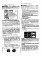
Gasoline containing up to 10% ethanol (El0) is acceptable for use in this machine,
The use of any gasoline exceeding 10% ethanol ([5t0) will void the product warranty.
Esta mdquina puede utilizar gasotina con un contenido de hasta el 10% de etanol (EIO).
El uso de una gasotina que supere el 10% de etanol (El0) anular,_ la garantia del producto.
Sears Brands Management Corporation, Hoffman Estates, IL 60179 U.S.A.
Visit our Craftsman website:www.sears.com/craftsman
*_ taredbytheengine
manufacturer
581859749
Warranty .................................................. 2
Safety Rules ............................................ 3
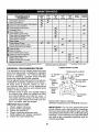
Product Specifications ............................. 6
Assembly!Pro-Operation ......................... 8
Operation..... .......................................... 13
Maintenance Schedule .......................... 21
Maintenance ..........................................
21
Service and Adjustments ....................... 26
Storage ..................................................
31
Troubleshooting
.....................................
32
Sears Service .......................... Back Cover
Craftsman Riding Equipment Warranty
CRAFTSMAN FULL WARRANTY
FOR TWO YEARS from the date of purchase, all non-expendable parts of this riding equipment are
warranted against any defects in matedal or workmanship. A defective non-expendable part well
receive free in-home repair or replacement if repair is impossible.
FOR FIVE YEARS from the date of purchase, the frame and front axle of this riding equipment are
warranted against any defects in material or workmanship. A defective frame or front axle will receive
free in-home repair or replacement if repair is impossible.
FOR 90 DAYS from the date of purchase, the battery (an expendable part) of this riding equipment
is warranted against any defects in material or workmanship (our testing proves that it will not hold a
charge). A defective battery will receive free in-home replacement.
ADDITIONAL LIFETIME LIMITED WARRANTY on CAST iRON FRONT AXLE (if equipped)
FOR AS LONG AS IT IS USED by the original owner after the t_tthyear from the date of purchase, the
cast iron front axle (if equipped) of this riding equipment is warranted against any defects in material or
workmanship. With proof of purchase, a defective cast front axle will receivefree in-home replacement.
WARRANTY SERVICE
For warranty coverage details to obtain free repair or replacement, call 1-800-659-5917 or visit the
web site: www.craftsman.com
in all cases above, if part repair or replacement is impossible, the riding equipment will be replaced
free of charge with the same or an equivalent model.
All of the above warranty coverage is void if this riding equipment is ever used while providing
commercial services or if rented to another person.
This warranty covers ONLY defects in material and workmanship. Warranty coverage does NOT
include:
,
Expendable parts (except battery) that can wear out from normal use within the warranty period,
including but not limited to blades, spark plugs, air cleaners, belts, and oil filters.
• Standard maintenance servicing, oiI changes, or tune-ups.
° Tire replacement or repair caused by punctures from outside objects, such as nails, thorns,
..............................
stumps_0r glass.
...................................................
• Tire or wheel replacement or repair resulting from normal wear, accident, or improper operation or
maintenance.
• Repairs necessary because of operator abuse, including but not limited to damage caused by
towing objects beyond the capability of the riding equipment, impacting objects that bend the
frame, axle assembly or crankshaft, or over-speeding the engine.
• Repairs necessary because of operator negligence, including but not limited to, electrical and
mechanical damage caused by improper storage, failure to use the proper grade and amount
of engine oil, failure to keep the deck clear of flammable debris, or failure to maintain the riding
equipment according to the instructions contained in the operator's manual,
• Engine (fuel system) cleaning or repairs caused by fuel determined to be contaminated or oxidized
(stale), in general, fuel should be used within 30 days of its purchase date.
° Normal deterioration and wear of the exterior finishes, or product label replacement.
Thiswarrantygivesyou specificlegal rights, and you may also have other rightswhich vary from
stateto state,
Sears Brands Management Corporation, Hoffman Estates, IL 60179
2
_DANGER:
This cutting machine is capable of amputating hands and feet and
throwing objects. Failure to observe the following safety instructions could result
in serious injury or death.
•
Neverdirectdischarged materialtoward
anyone. Avoid discharging material
against a wall or obstruction. Material
may ricochet back toward the operator.
Stop the blades when crossing gravel
surfaces,
_IkWARNING: Do not coast down a hill in
• Do not operate machine without the enneutral, you may lose control of the tractor.
tire grass catcher, discharge chute, or
other safety devices in place and working.
_kWARNING:
Tow only the attachments
• Slow down before turning.
that are recommended by and comply with
• Never leave a running machine unatspecifications of the manufacturer of your
tended. Always turn off blades, set
tractor. Use common sense when towing.
parking brake, stop engine, and remove
Operate only at the lowest possible speed
keys before dismounting,
when on a slope. Too heavy of a load, while
• Disengage blades when not mowing.
on a slope, is dangerous. Tires can lose
Shut off engine and wait for all parts to
traction with the ground and cause you to
come to a complete stop before cleaning
lose control of your tractor,
the machine, removing the grass catcher,
or unclogging the discharge chute.
_ILWARNING: Engine exhaust, some of
• Qperate machine only in daylight or good
its constituents, and certain vehicle compoartificial light.
nents contain or emit chemicals known to
• Do not operatethe machine while under
the State of California to cause cancer and
the influence of alcohol or drugs.
birth defects or other reproductive harm.
• Watch for traffic when operating near or
A(_WARNING: Battery posts, terminals and
crossing roadways.
related accessories contain lead and lead • Useextracare when loading or unloading
the machine into a trailer or truck.
compounds,chemicalsknowntothe Stateof
California to cause cancer and birth defects
• Always wear eye protection when operating machine.
or other reproductive harm. Wash hands
• Data indicates that operators, age 60
after handling=
years and above, are involved in a large
I, GENERAL OPERATION
percentage of riding mower-related injuries. These operators should evaluate
• Read, understand, and follow allinstructheir ability to operate the riding mower
tions on the machine and in the manual
safely enough to protect themselves and
before starting.
others from
serious
injury.
• Do not put hands or feet near rotating
.
.
.
"arts or under the machine Kee_ clear
" Followthe manufacturer's recommenda _
P
_
t_onfor
wheel
weights
or
counterweights
.........................
of the discharge opening ai' all tirnes, ........................
Keep machine free of grass, leaves o
• Only allow responsible adults, who are
otherdebris build-up which can touch ho
familiar with the instructions, to operate
exhaust/engine parts and burn, Do not
the machine.
allow the mower to plow leaves or other
• Clearthe area of objects such as rocks,
debris which can cause build-up to octoys, wire, etc,, which could be picked
cur. Clean any oil or fuel spillage before
up and thrown by the blades.
operating or storing the machine. Allow
• Be sure the area is clear of bystanders
machine to cool before storage,
before operating. Stop machine ifanyone
enters the area.
• Never carry passengers.
• Do not mow inreverse unless absolutely
necessary. Always lookdownand behind
before and while backing.
_ILWARNING: In order to prevent accidental starting when setting up, transporting,
adjusting or making repairs, always disconnect spark plug wire and place wire where
it cannot contact spark plug,
3
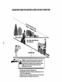
IL SLOPE OPERATION
Slopes are a major factor related to tossof
control and tip-over accidents, which can
result in severe injury or death. Operation
on all slopes requires extra caution. If you
cannot back uptheslope or if you feel uneasy
on it, do not mow it.
• Mow up and down slopes, not across.
• Watch for holes, ruts, bumps, rocks, or
other hidden objects. Uneven terrain
could overturn the machine. Tall grass
can hide obstacles.
• Choose a low ground speed so that you
will not have to stop or shift while on the
slope.
• Do not mow on wet grass, Tires may lose
traction.
Always keep the machine in gear when
going down slopes, Do not shift to neutral
and coast downhill.
• Avoid starting, stopping, or turning on a
slope. Ifthetireslosetraction, disengage
the blades and proceed slowly straight
down the slope.
• Keep all movement on the slopes slow
and gradual.
Do not make sudden
changes in speed or direction, which
could cause the machine to roll over.
• Use extra carewhile operating machine
with grass catchers or other attachments;
they can affect the stability of the machine. Do no use on steep slopes.
• Do not try to stabilize the machine by
putting your foot on the ground,
• Do not mow near drop-offs, ditches,
or embankments. The machine could
suddenly roll over if a wheel is over the
edge or if the edge caves in.
•
•
•
•
•
,
Keep children out of the mowing area
and inthe watchful care of a responsible
adult other than the operator.
Be alert and turn machine off if a child
enters the area.
Before and while backing, look behind
and down for small children.
Never carrychildren, evenwiththe blades
shutoff. They mayfall off and be seriously
injured or interfere with safe machine
operation. Children who have been given
rides inthe past may suddenly appear in
the mowing area for another ride and be
run over or backed over by the machine.
Never allow children to operate the machine.
Use extra care when approaching blind
corners, shrubs, trees, or other objects
that may block your view of a child.
IV. TOWING
- Tow only with a machine that has a hitch
designed for towing. Do not attach towed
equipment except at the hitch point.
• Followthe manufacturer's recommendation for weight limits for towed equipment
and towing on slopes.
• Never allow children or others in or on
towed equipment.
• On slopes, the weight ofthetowed equipment may cause loss of traction and loss
of control.
• Travel slowly and aIIow extra distance to
stop.
V. SERVICE
SAFE HANDLING OF GASOLINE
To avoid personal injury or property damage, use extreme care in handling gasoline,
Gasoline is extremely flammable and the
III. CHILDREN
"WA
NJURED
RNING: CHILDRENCANBE
................
BYTHiS EQUIPMENT.The American Academy of Pediatrics recommends that children
be a minimum of t 2 year of age before operating a pedestrian controlled lawn mower
and a minimum of 16 years of age before
operating a riding lawn mower.
Tragic accidents can occur if the operator
is not alert to the presence of children.
Children are often attracted to the machine
and the mowing activity. Never assume
that children will remain where you last
saw them.
vapors
are explosive.
Extinguish
alt cigarettes; cigars, pipes,
and other sources of ignition.
° Use only approved gasoline container.
• Never remove gas cap or add fuel with
the engine running. Allow engine to cool
before refueling.
• Never fuel the machine indoors.
• Neverstorethemachineorfuelcontainer
where there is an open flame, spark, or
pilot light such as on a water heater or
other appliances.
• Never fill containers inside a vehicle or
on a truck or trailer bed with plastic liner,
Always place containers on the ground
away from your vehicle when filling.
4
• Remove
gas-powered
equipment
from •
thetruckortrailerandrefuel
itonthe
ground.
Ifthisisnotpossible,
thenrefuel •
such
equipment
withaportable
container,
rather
thanfroma gasoline
dispenser
nozzle.
• Keep
thenozzle
incontact
withtherim .
ofthefueltankorcontainer
opening
at
alltimes
untilfueling
iscomplete.
Donot
•
useanozzle
lock-open
device.
• Iffuel
isspilled
onclothing,
change
cloth•
ingimmediately.
• Neveroverfillfueltank.
Replace
gascap
andtighten
securely.
GENERAL SERVICE
-
Nevertamperwith safetydevices. Check
their proper operation regularly.
Keep machine free of grass, leaves, or
other debris build-up. Clean oil or fuel
spillage and remove any fuel-soaked debris, Allow machine to cool before storing.
If you strike a foreign object, stop and
inspectthe machine. Repair, if necessary,
before restarting.
Never make any adjustments or repairs
with the engine running.
Checkgrass catcher components and the
discharge chute frequently and replace
with manufacturer's recommended parts,
when necessary.
Mowerbladesaresharp. Wraptheblade
or wear gloves, and use extra caution
when servicing them,
Checkbrakeoperationfrequently. Adjust
and service as required.
.
•
Never operate machine in a closed area.
Keep all nuts and bolts tightto be surethe
equipment is in safe working condition.
•
• Be alert and turn machine off if a child
Maintain or replace safety and instruction
enters the area.
labels, as necessary.
• Before and while backing, look behind
Be sure the area is clear of bystanders
and down for small children.
beforeoperating. Stop machine ifanyone
• Mow up and down slopes (15° Max), not
enters the area.
across,
Never carry passengers.
• Choose a low ground speed so that you
Do not mowin reverse unless absolutely
will not have to stop or shift while on the
necessary. Always look down and behind
slope.
before and while backing.
° Avoid starting, stopping, or turning on a
Never carry children, even with the
slope, Ifthetires Iosetraction, disengage
blades shut off, They may fall off and
be seriously injured or interferewith safe .................
the blades and proceed slowly straight .........
machine operation, Children who have
down the slope.
• If machine stops while going uphill,
been given rides inthe pastmay suddenly
disengage blades, shift into reverse and
appear in the mowing area for another
back down slowly.
ride and be run over or backed over by
• Do notturn onstopes unless necessary,
the machine.
and then, turn slowly and gradually
Keep children out of the mowing area
. downhill, if possible.
" and in the watchful care of a responsible
• Whenloadingorunloadingthismachine,
adult other than the operator.
do not exceed the maximum recommended operation angle of 15°.
•
•
•
•
•
PRODUCT
SPECIFICATIONS
Gasoline Capacity
and type:
3 Gallons/11,35 L
Regular Unleaded
Oil Type:
(API: SG-SL)
SAE 10W30 (above 32°F/0°C
SAE 5W30 (below 32°F/0°C
Oil Capacity:
64 Oz.l1,96
Spark Plug:
Champion RC12YC
(Gap: .030"/0.76 mm)
Charging
15 Amps @ 3600 RPM
System:
L
Battery:
AmpiHr:
Min. CCA:
Case size:
28
230
U1R
Blade Bolt Torque:
45-55 Ft. Lbs./62-75
Nm
CONGRATULATIONS on your purchaseof
a new tractor. It has been designed, engineered and manufactured to give you the best
possible dependability and performance.
Should youexperience any problem you cannot easily remedy, please contact a Sears or
other qualified service center. We have competent, well-trained representatives and the
proper tools to service or repair this tractor.
Pfease read and retain this manual. The
instructions will enable you to assemble
and maintain your tractor properly. Always
observe the "SAFETY RULES".
CUSTOMER
RESPONSIBILITIES
• Read and observe the safety rules.
• Follow a regular schedule in maintaining,
caring for and using your tractor.
• Follow instructions under "Maintenance"
and "Storage" sections ofthis manual.
. Wear proper Personat Protective Equipment (PPE) while operatingthis machine,
including(at a minimum) sturdy footwear,
eye protection, and hearing protection.
Do not mow in shorts and/or open toed
footwear.
• Always letsomeone knowyou are outside
mowing.
an internal combustion engine and should
not be used on or near any unimproved
forest-covered, brush-covered or grasscovered land unJessthe engine's exhaust
system is equipped with a spark attester
meeting applicable local or state taws (if
any). tf a spark arrester is used, it should
be maintained in effective working order by
the operator.
In the state ofCaliforniathe above isrequired
by law (Section 4442 of the California Public
Resources Code). Other states may have
similar laws. Federal laws apply on federal
lands, A spark arrester for the muffler is
avai[ablethroughyour nearest Searsservice
center (See REPAIR PARTS manual).
REPAIR PROTECTION AGREEMENTS
Congratulations on making a smart purchase. Your new Craftsman® product is
designed and manufactured for years of
dependable operation. But like all products,
it may require repair from timeto time.That's
when having a Repair Protection Agreement
can save you money and aggravation.
Purchase a Repair Protection Agreement
now and protect yourself from unexpected
hassle and expense.
Here's what's included in the Agreement:
Expert service byour 12,000 professional
repair specialists.
• Unlimited service and no chargefor parts
and labor on all covered repairs.
Product replacement if your covered
product can't be fixed.
•
Discount of 10% from regular price of
service and service-related parts not
covered by the agreement; also, 10% off
regular price of preventive maintenance
check.
•
Fast help by phone - phone support
from a Sears representative on products
requiring in-home repair, plus convenient
repair scheduling.
Once you purchasetheAgreement, asimple
phone call is all that it takes for youto schedule service. Youcan call anytime day or night,
or schedule a service appointment online.
Sears has over 12,000 professionalrepair
specialists, who have access to over 4.5
me KtnClOTpOes
y
to hetp prolongthelifeofyournewpurchase
for years to come. Purchase your Repair
Protection Agreement today!
Some limitations and exclusions apply,
For prices and additional information call
1-800-827-6655,
SEARS INSTALLATION SERVICE
For Sears professional installation of home
appliances, garage door openers, water
heaters, and other major home items, inthe
U.S.A. call 1-8004-MY-HOME®
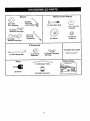
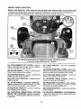
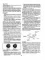
Mower
Mower
©
Front Wheel
(2) Rear q_
(5)1-3/16
Lift Link
O.D. Washem
_'_j
(1) Shoulder Bolt
Assemblies _
(I) I-I/40.D.
Washer
(1) Small
Retainer Springs
\
(1) Front \_
Lift Link
Retainer Springs
\_-_
Assembly
(1) Wheel
_
(1) 3,/8-16
Loeknut
If Equipped
®
(1) Anti-Sway Bar
,J,,,,,,,,,,,,,
(1) 3/40.D.
Washers
,i,,,,,,,,,,,,,,,,,,,
*Installed by Dealer
(t) Small Retainer
Springs
,,
Keys
!lll
*Brush Guard Kit
..........................
Slope Sheet
(1) Oil Drain Tube
(21 Keys
(11 Quick Connect
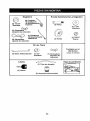
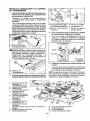
Your new tractor has been assembled at the factory with exception of those parts le_t
unassembled for shipping purposes. To ensure safe and proper operation of your tractor
all parts and hardware you assemble must be tightened securely. Use the correct tools
as necessary to ensure proper tightness.
TOOLS REQUIRED FOR ASSEMBLY
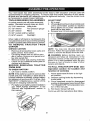
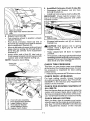
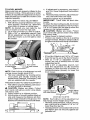
ADJUST SEAT
1. Sit in seat.
A socket wrench set will make assembly
easier. Standard wrench sizes are listed.
2, Lift up adjustment lever (A) and slideseat
until a comfortable position is reached
(2) 7/16" wrenches Utility knife
which allows you to press clutch/brake
(1) 1/2" wrench
Tire pressure gauge
pedal all the way down.
(1) 3/4" wrench
Pliers
3. Release lever to lock seat in position,
(1) 3/4" socket w/drive ratchet
(1) 9/16" wrench
Flashlight
When right or left hand is mentioned in this
manual, itmeanswhenyouare intheoperating
position (seated behind the steering wheel),
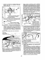
TO REMOVE
TRACTOR
FROM
CARTON
UNPACK CARTON
NOTE: You may now roll your tractor off
the skid, Follow the appropriate instruction
• Remove all accessible loose parts and
below to remove the tractor from the skid,
parts cartons from carton.
• Cut along dotted lines on al! four panWARNING: Before starting, read, unels of carton. Remove end panels and
derstand and follow all instructions in the
lay side panels flat.
Operation section of this manual. Be sure
• Remove mower and packing materials.
tractor is in a well-ventilated area. Be sure
• Check for any additional loose parts or
the area in front of tractor is clear of other
cartons and remove.
people and objects,
BEFORE
REMOVING
TRACTOR
TO ROLL TRACTOR OFF SKID (See
FROM SKID
Operation
section for location and
TO CHECK BATTERY
function
of
controls)
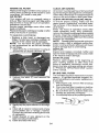
1. Lift hood to raised position.
1,
Raise
attachment
lift lever to its highNOTE: If this battery is put intoservice after
est position.
month and year indicated on label (label is
located between terminals) charge battery
2, Release parking brake by depressing
for minimum of one hour at 6-10 amps. (See
brake pedal.
"BATTERY" in Maintenance section of this
3. Place freewheel control in disengaged
manual for charging
• 'instructions)
"
.
positiontodisengagetransmission(See
...........
For battery and battery cable installation..............
'TOTRANSPORT _inthe Operation sec ..........
see "REPLACING BATTERY" in the
tion of this manual).
"Service and Adjustments" section in
4. Roll tractor forward off skid.
this manual.
Continue with the instructionsthat follow.
be!
8
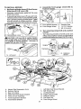
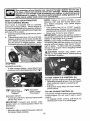
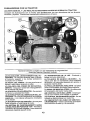
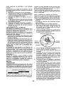
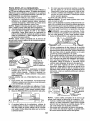
TO INSTALL MOWER
1. Set Parking Brake Lever (P) And Lower
Attachment Lift Lever (N).
• Depress clutch/brake pedal all the way
down and hold.
• Pull parking brake lever (P) up and hold,
release pressure from clutch/brake pedal,
then release parking brake lever. Pedal
should remain in brake position. Make
sure parking brakewi]l holdtractorsecure.
2.
Assemble front
front of mower,
gauge
H, Front Mower Bracket
VV, Front Gauge Wheel
3, Turn steering wheel
mower,
_CAUTION:
Lift {ever (N) is spring loaded.
Have a tight grip on lift lever, tower it slowly
and engage in lowest position. Lift lever is
located on lef_ side of fender.
Mower Side Suspension Arms
Retainer Spring
Rear Lift Link(s)
Right Side Rear Mower Bracket
Front Lift Link Assembly
Front Suspension Bracket
Front Mower Bracket
ON) to
X, Shoulder Bolt
Y. 1t/40.D. Washer
Z. 3,/8-16 Locknut
left and position
• Turn steering wheel to the left as far as it
wil! go and position mower on right side of
tractorwith deflectorshield
(Q) to the right,
Front
Q.
A,
B.
C,
D.
E,
E
H,
wheel
Deflector
ShJeld
I, Left Side Rear Mower Bracket
K. Belt Tension Rod
L.
M.
Q.
S.
W.
Locking Bracket
Engine Clutch Pultey
Deflector Shield
Anti-Sway Bar
Front Gauge Wheel
4. Slide mower under tractor.
• Bring belt forward and chock belt for
proper routing inali mower pulleygrooves,
NOTE: Be sure mower side suspension
arms (A) are pointing forward before sliding
mower under tractor.
• Slide mower under tractor until it is
centered under tractor.
•
8
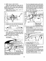
D. RightSide Rear
Mower Bracket
S, Anti-SwayBar
T. TransaxleBracket
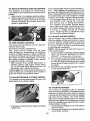
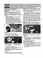
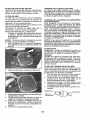
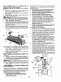
5. Install anti-sway bar (S) (if equipped)
I
Anti-Sway
Bar (S)
6,
Towards"tl _
Mower Deck
•
90 = End
Integrated
Washer
Pivot the integrated washer end of antisway bar (S)towards mower deck bracket
on right side of mower, Insert integrated
washer end of bar into hole in rearmower
bracket (D). Move mower as needed to
insert integrated washer end of bar into
rear mower bracket (D).
Secure with small washer and small
retainer spring as shown.
End
•
From right side of mower, first insert
90 ° end of anti-sway bar (S) into hole in •
transaxle bracket (T), located near left
rear tire in front of transaxle,
NOTE: Flashlight may be helpful.
Anti-Swa, Bar
_']
.4!:;_'
_.:.....................
(S)
Attach mower side suspension arms
(A) to chassis,
Position front hole in side suspension arm
(A) over pin on outside of tractor chassis
and secure with large washer and large
retainer spring (B).
Repeat on opposite side of tractor.
D. Right Side Rear Mower Bracket
NOTE: Depending on model, bracket (_ may
be differentthan shown but hole for anti-sway
bar will be in same position/location,
•
10
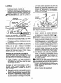
Attach rear lift links (C)
Insert rod end of rear lift link (C) intohole
(U) in tractor lift shaft suspension arm
and pivot link down to mower.
Lift rear corner of mower and position slot
in link assembly over pin on rear mower
bracket (D) and secure with largewasher
and large retainer spring.
Repeat on opposite side of tractor.
9
•
Install Belt On Engine Clutch Pulley (M)
Disengage belt tension rod (K) from
locking bracket (L).
o Install belt onto engine clutch pulley (M).
IMPORTANT: Check belt for proper routing in all mower pulley grooves and under
mandrel covers.
X
C. RearLift Link(S)
D, Right Side Rear Mower Bracket
U, Hole
8 Attach front link (E)
• Turn steering wheel to position wheels
straight forward.
• From front of tractor, insert rod end of
front link (E) through front hole in tractor
front suspension bracket (F).
• Move to leftside of mower and and insert
large retainer spring (G) through hole in
front link (E) behind front suspension
bracket (F).
• Insert other end of link (E) into hole in
front mower bracket (H) and secure with
washer and small retainer spring (J).
NOTE: Requires deck lifting.
M,Engine
ClutchPulley
Engage belt tension rod (K) on locking
bracket (L),
AOjLCAUTION: Belt tension rod is spring
loaded. Have a tight grip on rod and
engage slowly.
• Raise attachment lift lever to highest
position.
• Ifnecessary, adjust gauge wheels before
operating moweras shown inthe owner's!
operator's manual. Check gauge wheels,
deck level and rake settings.
Front Link
Location
CHECK TIRE PRESSURE
The tires on your tractor were overinflated
atthe factory for shipping purposes. Correct
tire pressure is important for best cutting
performance.
• Reducetirepressureto PSI shown on tires.
CHECK DECK LEVELNESS
For best cutting results, mower housing
should be properly leveled. See "TO LEVEL
MOWER" in the Service and Adjustments
section of this manual.
CHECK FOR PROPER POSITION OF
ALL BELTS
See the figures that are shown for replacing
motion and mower blade drive belts in the
Service andAdjustments section ofthis manual. Verifythatthe belts are routed correctly.
E,
F,
G,
H,
J.
M,
CHECK BRAKE SYSTEM
After you learn how to operate your tractor,
check to seethatthe brake is operating properly. See"TO CHECK BRAKE" inthe Service
and Adjustments section of this manual.
Front Lift Link Assembly
Front Suspension Bracket
Large Retainer Spring
Front Mower Bracket
Small Retainer Spring
Engine Clutch Pulley
tl
t_CHECKLIST
Before you operate your new tractor, we
wish to assure that you receive the best
performance and satisfaction from this
Quality Product.
Please review the following checklist:
J All assembly instructions have been
completed.
No remaining loose parts in carton.
v f Battery isproperly prepared and charged.
J" Seat is adjusted comfortably and tightened securely.
v _ All tires are properly inflated. (For shipping purposes, the tires were ovednflated
at the factory).
_/Be sure mower deck is properly leve_ed
side-to-sideifront-to-rear for best cutting
results. (Tires must be properly inflated
for leveling).
J Check mower and drive belts, Be sure
they are routed properly around pulleys
and inside all belt keepers.
vf Check wiring. See that all connections
are still secure and wires are properly
clamped.
J" Before driving tractor, be sure freewheel
control is in"transmission engaged" position (see "To Transport" in the Operation
section of this manual).
While learning how to use your tractor, pay
extra attention to the following important
items:
J" Engine oil is at proper level.
J" Fuettankisfilledwithfresh, clean, regular
unleaded gasoline.
J Become familiar with all controls, their
location and function. Operate them
before you start the engine,
J" Be sure brake system is in safe operating
.......condition. ...........................................................................
vt Be sure Operator Presence System and
Reverse Operation System (ROS) are
working properly (See the Operation and
Maintenance sections in this manual).
#" It is important to purge the transmission
before operating your tractor for the first
time. Follow proper starting and transmission purging instructions (See "TO
START ENGINE" and "PURGE TRANSMISSION" inthe Operation section ofthis
manual).
12
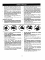
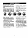
These
symbols
mayappear
onyourtractor
orinliterature
supplied
withtheproduct.
Learn
andunderstand
theirmeaning.
R
N
REVERSE
H
NEUTRAL
lkl
L
HIGH
LOW
CHOKE
FAST
SLOW
IGNITION
i,m,i
ENGINE
LIGHTS
OFF
REVERSE
OPERATION
ON
FUEL
ENGINE
BATTERY
ON
ENGINE
REVERSE
START
PARKING
FORWARD
BRAKE
CRUISE
MOWER
HEIGI'rF
MOWER
SWITCH
LIFT
CLUTCH/BRAKE
PEDAL
CONTROL
®@@@®
ATTACHMENT
CLUTCH
DISENGAGED
A'n'ACHMENT
CLUTCH
ENGAGED
OANGER,
KEEP HANDS
AND FEET AWAY
KEEPAREACLEAR
(SEE
SLOPEHAZARDS
SAFETY
RULES
SEC_ON)
DANGER
will result indicates
in death aorhazard
seriouswhich,
injury.if not avoided,
FREE
(Automatic
WARNING
hazard
which,
if not avoided,
could resultindicates
in deatha or
serious
injury.
WHEEL
Modelsoniy)
CAUTION
indicates
a hazard
which, if
not avoided,
might result
in minor
or moderate
injury,
&
CAUTION when used without the aied symbol,
indicates a situation that could result in damage
to the tractor and/or engine.
Failure to follow instructions
could result in serious injury or
death. The safety alert symbol
is used to identify safety information about hazards which can
result in death, serious injury
and/or property damage.
J
HOT SURFACES indicates a hazard which,
if not avoided, could result in death, serious injury
and/or property damage.
FIRE indicates a hazard which, if not avoided,
could result in death, serious injury and/or
property damage.
13
KNOW YOUR TRACTOR
READ THIS MANUAL AND SAFEr{ RULES BEFORE OPERATING YOUR TRACTOR
Compare the illustrations with your tractor to familiarize yourself with the locations of
various controls and adjustments, Save this manual for future reference.
Our tractors conform to the applicable safety standards of the
American National Standards Institute.
(A) ATTACHMENT
LIFT LEVER - Used to
raise and lower the mower or other attach-
(H) LIGHT SWITCH
on and off.
- Turns the headlights
ments mounted to your tractor.
(J) CRUISE CONTROL
(B) BRAKE PEDAL - Used for braking the
tractor and starting the engine,
forwardmovementoftractoratdesiredspeed
without holding the forward drive pedal.
LEVER- Used to set
(C) PARKING BRAKE - Locks clutch/brake
(K) FORWARD DRIVE PEDAL
-pedal into the brake position. ......................................
forward movement of tractor,
- Used for
(D) THROTTLE CONTROL- Used to control
engine speed,
(E) ATTACHMENT CLUTCH SWITCH Used to engage the mower blades, or other
attachments mounted to your tractor.
(M) FREEWHEELCONTROL- Disengages
transmission for pushing or slowly towing
the tractor with the engine off,
(F) IGNITION SWITCH - Used for starting
and stopping the engine.
(N) CHOKE CONTROL- Used when starting
a cold engine.
(G) REVERSE OPERATION SYSTEM
(ROS) "ON" POSITION - Allows operation
of mower or other poweredattachmentwhife
in reverse.
(P) S ERVICE REMINDER 1HOUR METER
- Indicates when service is required for the
engine and mower.
(L) REVERSE DRIVE PEDAL- Used for
reverse movement of tractor.
14
lull
i
..........
i
n
IIH,
U
I IIIIIIIIl,ll,ll,
I,,,I
the eyes, which can result in severe eye damage. Always wear safety
glasses or eye shields while operating your tractor or performing any
adjustments
We recommend
safety glasses
a
The operationorofrepairs.
any tractor
can result instandard
foreign objects
thrown or
into
wide vision safety mask worn over spectacles.
............
|
|
|J
!
NOTE: Failure to move throttle control
between half and full speed (fast) position, before stopping, may cause engine
to "backfire".
* Turn ignition key (F) to "STOP" position
and remove key. Always remove keywhen
leavingtractorto prevent unauthorized use,
• Never use choke to stop engine.
IMPORTANT: Leaving the ignition switch in
any position other than "STOP" will cause the
battery to discharge and go dead,
NOTE: Under certain conditions when tractor
is standing idle with the engine running, hot
engine exhaust gases may cause "browning" of grass. To eliminate this possibility,
always stop engine when stopping tractor
on grass areas.
CAUTION: Always stop tractor completely, as described above, before leaving
the operator's position.
HOW TO USE YOUR TRACTOR
TO SET PARKING BRAKE
Your tractor is equipped with an operator
presence sensing switch. When engine is
running, any attempt bythe operator to leave
the seat withoutfirst setting the parking brake
will shut off the engine.
t. Depress brake pedal (B) altthe way down
and hold.
2, Pull parkingbrake lever (C) up and hold,
release pressure from brake pedal (B),
then release parking brake lever, Pedal
should remain in brake position. Make
sure parking brake willholdtractor secure.
STOPPING
MOWER BLADES • To stop mower blades, move attachment
clutch controlto disengaged position (i'll).
TO USE THROTTLE
CONTROL
(D)
Always operate engine at full speed (fast).
• Operating engine at less than futl speed
(fast) reduces engine's operating el............
ficiency_ .................................................................
:
• Full speed (fast) offers the best mower
performance.
(1_)
Attachment
Clutch Control
"Engaged ....
(1_)
Attachment
Clutch Control
Disengaged"
TO USE CHOKE CONTROL (N)
Usechoke control whenever you are starting
a cold engine. Do not use to start a warm
engine.
• To engage choke control, pull knob out.
Stowty push knob in to disengage.
GROUND DRIVE . Tostop ground drive, depress brake pedal
all the way down.
IMPORTANT: Forward and reverse drive
pedals return to neutral position when not
depressed,
ENGINE • Movethrottle control (D) between half and
full speed (fast) position.
15
TO MOVE FORWARD AND BACKWARD
The direction and speed of movement is
controlled by the forward and reverse drive
pedals.
1. Start tractor and release parking brake.
2. Slowty depress forward (K) or reverse(L)
drive pedal to begin movement. Ground
speed increases the further down the
pedal is depressed.
The cutting height range isapproximately 1"
to 4". The heights are measured from the
ground to the blade tip withthe engine not running.These heights areapproximate andmay
vary depending upon soil conditions, height
of grass and types of grass being mowed.
• The average lawn should be cut to approximately 2-I/2" during the cool season and to over 3" during hot months.
For healthier and better looking lawns,
mow often and after moderate growth.
• For best cutting performance, grass over
6 inches in height should be mowed
twice. Make the first cut relatively high;
the second to desired height,
TO ADJUST
GAUGE WHEELS
Gauge wheels are properly adjusted when
they are slightly offthe ground when mower
is at the desired cutting height in operating
position. Gauge wheels then keep the deck
in proper position to help prevent scalping
in most terrain conditions.
NOTE: Adjust gauge wheels with tractor on
a flat level surface,
1. Adjust mower to desired cutting height
(See "TO ADJUST MOWER CUTTING
HEIGHT" in this section of manual).
2. With mower in desired height of cut position, gaugewheels
should be assembled
so they are slightly off the ground. Install
gauge wheel in appropriate hole. Tighten
securely.
3. Repeat for al!, installing gauge wheel in
same adjustment hole.
TO USE CRUISE CONTROL
The cruise control feature can be used for
forward travel only.
SYSTEM CHARACTERISTICS
The cruise control should only be used
while mowing or transporting on relatively
smooth, straight surfaces. Other conditions
such as trimming at slow speeds may cause
the cruise control to disengage. Do not use
the cruise control on slopes, rough terrian
or while trimmimg or turning.
• With forward drive pedal depressed to
desired speed, pull cruise control lever
(J) up and hold while lifting your foot off
the pedal, then release the lever.
Todisengagethe cruise control, depress the
brake pedal, tap on forward drive pedal or
push the cruise control lever down.
TO ADJUST MOWER CUTTING HEIGHT
The position of the attachment lift lever (A)
determines the cutting height.
TO OPERATE MOWER
Your tractor is equipped with an operator
presence sensing switch. Any attempt bythe
operator to leave the seat with the engine
running and the attachment clutch engaged
will shut off the engine. You must remain
fully and centrally positioned in the seat to
prevent the engine from hesitating or cutting
offwhen operating your equipment on rough,
rolling terrain or hills.
1. Select desired height of cut with attachment lift lever.
2. Start mower blades by engaging attachment clutch control,
• Put attachment lift lever in desired cutting
height slot.
16
TO STOP MOWER BLADES
• Disengage attachment clutch control.
TO OPERATE ON HILLS
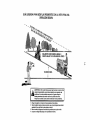
,d_WARNING: Do not drive up or down
hills with slopes greater than 15 ° and do
not drive across any slope. Use the slope
guide provided at the back of this manual.
• Choose the slowest speed before starting
up or down hilts.
• Avoidstoppingorchangingspeedon
hills,
• If stopping is absolutely necessary, push
brake pedal quickly to brake position and
engage parking brake,
• To restart movement, slowly release parking brake and brake pedal.
- Slowfy depress appropriate drive pedal to
slowest setting.
• Make all turns slowly.
J_I=CAUTION: Do not operate the mower
without either the entire grass catcher, on
mowers so equipped, or the deflector shield
(S) in place.
TO TRANSPORT
When pushing or towing your tractor, be
sure to disengage transmission by placing
freewheel control in freewheeling position,
Free wheel control is located at the rear
drawbar of tractor.
° Raise attachment lift to highest position
with attachment lift control.
• Pullfreewheel control outand into the slot
and release so it is held inthe disengaged
position.
• Do not push or tow tractor at more than
two (2) MPH.
• Toreengage transmission, reverse above
procedure.
REVERSE OPERATION SYSTEM (ROS)
Your tractor is equipped with a Reverse
Operation System (ROS). Any attempt by
the operatorto travel in the reverse direction
with the attachment clutch engaged will shut
off the engine unless ignition key is placed
in the ROS "ON" position.
_WARNING:
Backing up with the attachment clutch engaged while mowing is
strongly discouraged. Turningthe ROS"ON",
to allow reverse operation with the attachment clutch engaged, should only be done
when the operator decides it is necessary to
reposition the machine with the attachment
engaged. Do not mow in reverse unless
absolutely necessary.
USING THE REVERSE OPERATION
SYSTEM Only use if you are certain no children or
other bystanders will enter the mowing area.
t. Depress brake pedal all the way down.
NOTE; Toprotect hood from damage when
2. With engine running, turn ignition key
transporting your tractoron atruck oratrailer,
...........
coynte[c!gckw!se_to BQS ="ON"Position,
be sure hood is closed andsecured totractor.
3. Look down and behind before and ....................
use an _,ppr0pi:iate meai_sof tyinghood to .......
while backing,
tractor (rope, cord, etc.).
4, Slowly depress reverse drive pedal to
start movement.
TOWING CARTS AND OTHER ATTACHMENTS
5. When use of the ROS is no longer
needed, turn the ignition key clockwise
Tow only the attachments that are recomto engine "ON" position.
mendedby and comply with specifications
of the manufacturer of your tractor. Use
Engine "ON" Position
common sense when towing. Too heavy
ROS "ON" Position
(Normal Operating)
of a load, while on a slope, is dangerous.
Tires can lose traction with the ground and
cause you to lose contro] of your tractor.
O
17
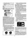
SERVICE REMINDER/HOUR METER
Service remindershows the total number of
hours the engine has run andindicateswhen
the engine or mower needs servicing. After
every 50 hoursof operationthe oil can icon
willstay on for 2 hoursoruntila manual reset
occurs. To reset the display manually turn
the ignition switch to the on position,then
the off position five times (1 second on, 1
second off). To service engine and mower,
see the Maintenance section of this manual.
Note: Service reminder runs when the
ignition key is in any position but "STOP".
For accurate reading, be sure key remains
in the "STOP" position when engine is not
running.
BEFORE STARTING THE ENGINE
CHECK ENGINE OIL LEVEL
The engine inyour tractor has been shipped,
from the factory, already filled with summer
weight oil.
1. Check engine oil with tractor on level
ground,
2. Unthread and remove oil flUcap/dipstick;
wipe oil off. Reinsert the dipstick into the
tube and rest oil fill cap on the tube. Do
notthread the cap onto thetube, Remove
and read oil level. If necessary, add oil
until "FULL['mark on dipstick is reached.
Do not overfill.
3. For cold weather operation you should
change oil for easier starting (See the
oil viscosity chart in the Maintenance
section of this manual).
4. To change engine oil, see the Maintenance section in this manual,
5, Fill fuel tank to bottom of filler neck, Do
not overfill. Use fresh, clean, regular
unleaded gasoline with a minimum of
87 octane. (Use of leaded gasoline
will increase
carbon
deposits
and reduce
CAUTION: Alcohol blended fuels (called
gasohol or using ethanol or methanol) can
attract moisture which leads to separation
andformation of acids during storage. Acidic
gas can damage thefuelsystem ofan engine
while in storage. Toavoid engine problems,
the fuel system should be emptied before
storage of 30 days or longer. Drain the gas
tank, start the engine and let it run until the
fuel lines and carburetor are empty. Use
fresh fuel nextseason. See Storage Instructions for additional information. Never use
engine or carburetor cleaner products inthe
fuel tank or permanent damage may occur.
TO START ENGINE
When starting the engine for the first time or
if the engine has run out of fuel, it will take
extra cranking time to move fuel from the
tank to the engine.
t. Be sure freewheel control is in the transmission engaged position.
2. Siton seat in operating position, depress
brake pedal and set parking brake.
3, Move attachment clutch to disengaged
position.
4. Move throttle control to fast position
5. Pull choke control out for a cold engine
start attempt. For a warm engine start
attempt the choke control may not be
needed.
NOTE: Before starting, read the warm and
cold starting procedures below.
6, tnsert key into ignition and turn key
clockwise to start position and release
key as soon as engine starts. Do not run
starter continuously for more than fifteen
seconds per minute, [f the engine does
not start after several attempts, push
choke control in, wait a few minutes and
try again. If engine still does not start,
pull the choke control out and retry.
WARM WEATHER STARTING (50°F/10°C
and.lead
oxide ...........
andabove)
valve life). Do
7. When engine starts, slowly push choke
not mix oil with gasoline. Purchase
fuel in quantities that can be used
within 30 days to ensure fuel freshness.
,iI_CAUTION: Wipe off any spilled oil or
fuel. Do notstore, spill oruse gasoline near
an open flame.
IMPORTANT: When operating in temperatures below 32°F (0°C), use fresh, clean
winter grade gasoline to help ensure good
cold weather starting.
8,
18
control in until the engine begins to run
smoothly. If the engine starts to run
roughly, pull the choke control out slightly
for a few seconds and then continue to
push the control in slowly,
The attachments and ground drive can
now be used. If the engine does not
accept the load, restart the engine and
allow itto warm up for one minute using
the choke as described above,
COLD WEATHER STARTING (50°F/10°C
and below)
7. When engine starts, slowly push choke
control in until the engine begins to run
smoothly. Continue to push the choke
control insmall steps allowing the engine
to accept small changes in speed and
toad, until the choke control is fully in.
If the engine starts to run roughly, pull
the choke control out slightly for a few
seconds and then continue to push the
control in slowly. This may require an
engine warm-up period from several
seconds to several minutes, depending
on the temperature.
AUTOMATIC TRANSMISSION 'WARM UP
Before driving the unit in cold weather, the
transmission should be warmed up as follows:
1. Be sure the tractor is on level ground.
2, Release the parking brake and let the
brake slowly return to operating position.
3, Allow one minute for transmission to
warm up. This can be done during the
engine warm up period.
4. The attachments can be used during the
enginewarm-up period after the transmission has beenwarmed up and may require
the choke control be pulled out slightly.
NOTE: If at a high altitude (above 3000
feet) or in cold temperatures (below 32°F)
the carburetor fuel mixture may need to be
adjusted for best engine pe_ormance (see
"TOAD JUST CARBURETOR inthe Service
and Adjustments section of this manual).
2. Disengage transmission by placing
freewheel control indisengaged position
(See _'TOTRANSPORT" in this section
of manual).
3. Sitting in the tractor seat, start engine.
After the engine is running, movethrottle
control to slow position. Disengage parking brake.
_JLCAUTION: At any time, during step 4,
there may be movement of the drivewheefs.
4. Depress forward drive pedal to full forward position andhold for five (5) seconds
and release pedal. Depress reverse drive
pedal to full reverse position and hold
for five (5) seconds and release pedal.
Repeat this procedure three (3) times.
5. Shutoff engine and set parking brake.
6. Engage transmission by placing freewheel control in engaged position (See
"TO TRANSPORT" in this section of
manual).
7. Sitting in the tractor seat, start engine.
After the engine is running, move throttle
control to half (1/2) speed. Disengage
parking brake,
8. Drive tractor forward for approximately
five feet then backwards for five feet.
Repeat this driving procedure three
times.
Your transmission is now purged and now
ready for normal operation.
PURGE TRANSMISSION
_,CAUTION:
Never engage or disengage
freewheel lever while the engine is running.
Toensure proper operationand performance,
it is recommended that the transmission be
purged before operating tractor for the first
time; This procedurewill remove anytrapped
air inside the transmission which may have
developed during shipping of your tractor.
IMPORTANT: Should your transmission
require removal for service or replacement,
itshould be purged after reinstallation before
operating the tractor,
1. Place tractor safely on a level surface that is clear of objects and open - with
engine off and parking brake set,
19
MOWING TIPS
• Tire chains cannot be used when the
mower housing is attached to tractor.
• Mower should be properly|eveled for best
mowing performance. See "TO LEVEL
MOWER HOUSING" in the Service and
Adjustments section of this manual.
• The left hand side of mower should be
used for trimming.
• Drive so that clippings are discharged onto
the area that has already been cut. Have
the cut area to the right ofthe tractor. This
will result in a more even distribution of
clippings and more uniform cutting.
• When mowing large areas, start byturning
to the right so that clippings will discharge
away from shrubs, fences, driveways,
etc. After one or two rounds, mow in the
opposite direction making left hand turns
until finished.
J
• If grass is extremely tall, it should be
mowed twice to reduce load and possible
fire hazard from dried clippings. Make
first cut relatively high; the second to the
desired height.
• Do not mow grass when it is wet. Wet
grass will plug mower and leave undesirable clumps. Allow grass to dry before
mowing.
• Always operate engine at full throttle
when mowing to assure better mowing performance and proper discharge
of material. Regulate ground speed by
selecting a low enough speed to give the
mower cutting performance as well as the
quality of cut desired.
• When operating attachments, select a
ground speed that will suit the terrain and
give best performance of the attachment
being used.
2O
A|
aEFo_E
SCHEDULE
...............
M NTE'NANCE
Check
Brake
Check
Tire
ODeral_Qn
V
Check operator
Presence & ROS Systems
Ik/
i
Check
Fasteners
V
C
Chec_JReplace
m
Lubrication
0
Check
C!e,an
Ch,eck
H_R
if
Pressure
{or Loose
_VERV
_AeHUSE s
....
Mower
f
EVEaV
s 1r
Oil
_
V'
V #
P_ate
if
.......
Cooling
.... if
.....................
Ch_ck En_ige Oil Level
if
if
Ikf
Change Bn¢line Oil (with oil filter)
Clean
G
I
Oil {without
_
oil fi_ter)
n
_.
,
..........
"
(if equ!pped)
I_
N
Replace
E
clean Engine CeeI_ng Fins
t_z
Replace Spark Plug
_
Replace
Filter
V'
I
.................
}nsbect Muffier/SperkArres_er'
Oil
V'
q_r_
A!,r F_Iter
Air Sci'ee
Air Filter Paper
BEFO_
V_,
Ch,esk Mower Level,r_ess
Check V-Belts
ChP_eg_ Engine
EVERY
SEASONSTO.A_
........
Steeling
Trensaxle
lo0
HQUNS
Blades
Level
Debris
EVERY
if
Chart
Battery
EVERY
kouas_ .O_S
{1_,;_
CP,rtr_ge
Replace Fuel Filter
.............
V _
V+2
....
if
LUBRICATION CHART
GENERAL RECOMMENDATIONS
The warranty on this tractor does not cover
items that have been subjected to operator
abuse or negligence.
To receive full value
from the warranty, operator must maintain
tractor as instructed in this manual.
_Steering
(_
Zerk
Some adjustments will need to be made periodically to properly maintain your tractor.
At least once a season, check to see if
you should make any of the adjustments
described in the Service and Adjustments
section of this manual.
Wheel
Bearing
Zerk
Pivot Bolts
Spindle
Zerk
Front Wheel
Bearing Zerk
Engine
Sector
Gear
• At east
once
a
year
you
shoud
rep
ace
_leech
-.. ..........
..............................
..
.............
the spark pug, c ean or rep ace air fl ter,
and check blades and belts for wear. A
Zerks
new spark plug and clean air filter assure
proper air-fuel mixture and help your engine run better and last longer,
(_General Purpose Grease
,,
(_RefertoMaintenance
ENGINE Section,
BEFORE EACH USE
1,
2.
3.
4.
5.
Check engine oil level.
Check brake operation.
Check tire pressure.
Check operator presence and
ROS systems for proper operation.
Check for loose fasteners.
IMPORTANT: Do not oil or grease the pivot
points which have special nylon bearings.
Viscous lubricants will attract dust and dirt
that will shorten the life of the self-lubricating
bearings. Ifyou feel they must be lubricated,
use only a dry, powdered graphite type lubricant sparingly.
21
TRACTOR
Always observe safety rules when performing any maintenance.
BRAKE OPERATION
If tractor requires more than five (5) feet to
stop at highest speed in highest gear on a
level, dry concrete or paved surface, then
brake must be serviced. (See "TO CHECK
BRAKE" in the Service and Adjustments
section of this manual).
TIRES
• Maintain proper air pressure in all tires
(See PSI on tires).
• Keep tires free of gasoline, oil, or insect
control chemicals which can harm rubber,
• Avoid stumps, stones, deep ruts, sharp
objects and other hazards that may
cause tire damage,
NOTE: To seal tire punctures and prevent
flat tires due to slow leaks, tire sealant
may be purchased from your local parts
dealer. Tire sealant also prevents tire dry
rot and corrosion.
OPERATOR PRESENCE SYSTEM AND
REVERSE OPERATION SYSTEM (ROS)
Be sure operator presence and reverse
operation systems are working properly. If
your tractor does not function as described, repair the problem immediately.
• The engine should not start unless the
brake pedal is fully depressed, and
the attachment clutch control is in the
disengaged position.
CHECK OPERATOR PRESENCE
SYSTEM
• When the engine is running, any attempt by the operator to leave the seat
withoutfirst setting the parking brake
should shut off the engine,
• When the engine is running and the
attachment clutch is engaged, any attempt by the operator to leave the seat
should shut off the engine.
The attachment clutch should never operate unless the operator is in the seat.
ROS "ON" Position
CHECK REVERSE OPERATION (ROS)
SYSTEM
• When the engine is running with the
ignition switch in the engine "ON" position and the attachment clutch engaged,
any attempt by the operator to shift into
reverse should shut off the engine,
• When the engine is running with the
ignition switch in the ROS "ON" position
and the attachment clutch engaged,
any attempt by the operator to shift into
reverse should NOT shut off the engine.
BLADE CARE
For best results mower blades must be
sharp. Replace worn, bent or damaged
blades.
_t, CAUTION: Use only a replacement
blade approved by the manufacturer of
your tractor, Using a blade not approved
by the manufacturer of your tractor is
hazardous, could damage your tractor and
void your warranty,
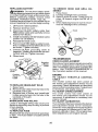
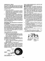
BLADE REMOVAL
t. Raise mower to highest position to allow
access to blades.
NOTE: Protect your hands with gloves and/
or wrap blade with heavy cloth.
2. Remove blade bolt by turning counterclockwise.
3. Instaflnewbladewithstamped"THISSIDE
UP" facing deck and mandrel assembly.
IMPORTANT: To ensure proper assembly,
center hole in blade must align with star on
mandrel assembly.
4, Install and tighten blade bolt securely
(45-55 Ft. Lbs. torque).
IMPORTANT: Special blade bolt is heat
treated.
Mandrel
___
Bl[_lade
Assembly
_(4_._%
_
___)
))
Alade Bolt "_%-_
/_L_
_Soeciai_..
-_",:_L_.__...
_'_._
" _
" "_/'"%_._'_-_..
\_r
//
_q_
v_.
CenterHole
BATTERY
Your tractor has a battery charging system
which is sufficientfor normal use, However,
periodic charging of the battery with an automotive charger will extend its life.
• Keep battery and terminals clean.
• Keep battery bolts tight.
• Keep small vent holes open.
• Recharge at 6-10 amperes for 1 hour.
Engine "ON" Position
(Normal Operating)
22
NOTE: The original equipment battery on
your tractor is maintenance free. Do not
attempt to open or remove caps or covers.
Adding or checking level of electrolyte is
not necessary.
TO CLEAN BATTERY AND TERMINALS
Corrosion and dirt on the battery and terminals can cause the battery to "leak" power.
1. Remove terminal guard.
2, Disconnect BLACK battery cable first
then RED battery cable and remove
battery from tractor.
3. Rinsethe batterywith plainwaterand dry,
4, Clean terminals and batten! cable ends
with wire brush until bright,
5. Coat terminals with grease or petroleum
jel]y.
6. Reinstall battery (See "REPLACING
BATTERY" in the SERVICE AND ADJUSTMENTS section of this manual).
TRANSAXLE MAINTENANCE
The transmission fan and cooling fins should
be kept clean to assure proper cooling, Do
not attemptto clean fan or transmission while
engine is running or while the transmission
is hot. To prevent possible damage to seals.
do not use high pressure water or steam to
clean transaxle.
• Inspect cooling fan to be sure fan blades
are intactand clean.
• Inspect cooling fins for dirt, grass clippings
and other materials. Toprevent damageto
seals, do not use compressed air or high
pressure sprayer to clean cooling fins.
TRANSAXLE PUMP FLUID
The transaxle was sealed at the factory and
fluid maintenance is not required for the life
of the transaxle. Should the transaxle ever
leak or require servicing, contact your nearest Sears or other qualified service center.
Change the oil after every 50 hours of operation or at least once a year if the tractor
is not used for 50 hours in one year.
Check the crankcase oil level before starting the engine and after each eight (8)
hours of operation.
TO CHANGE ENGINE OIL
Determine temperature range expected
before oil change, All oil must meet API
service classification SG-SL.
• Be sure tractor is on level surface,
• Oil will drain more freely when warm.
• Catch oil in a suitable container,
1. Remove oil fill cap]dipstick. Be careful
net to aliow dirt to enter the engine
when changing oil,
2. Remove yellow cap from end of drain
valve and install the drain tube onto
the fitting.
3. Unlock drain valve by pushing inward
slightly and turning counterclockwise.
OilDrain Vaive
__
Tube
Drain
To open,pullouton thedrainvalve,
5, After eli has drained completely, close
and tock the drain valve by pushing
nward and turning clockwise until the
pin is in the-iocked i_ositisnasstl0wn_
6. Remove the drain tube and replace thecap onto the end of the drain valve.
7, Refill engine with oil through oil flit dipstick tube. Pour slowly. Do not overfill.
For approximate capacity see "PRODUCT SPECIFICATIONS" section of this
manual,
8. Use gauge on elf fill cap/dipstick for
checking level. Insert dipstick into
the tube and rest the oil fill cap on the
tube. Do not thread the cap onto the
tube when taking reading, Keep oil
at "FULC line on dipstick. Tighten cap
onto the tube securely when finished,
4,
V-BELTS
.........................
-, ..........
;........ .
CheckV-be tsToraeter ora_onanawearalter
100 hours of operation and replace if necessary, The belts are not adjustable. Replace
belts if they begin to slip from wear,
ENGINE
LUBRICATION
Only use high quality detergent oil rated with
API service classification SG-SL. Selectthe
oil's SAE viscosity grade according to your
expected operating temperature.
23
ENGINE OIL FILTER
Replace the engine oil filter every season or
every other oil change if the tractor is used
more than 100 hours in one year.
AIR FILTER
Your engine will not run properly using a
dirty air filter. Service paper cartridge every
two months or every 25 hours of operation,
whichever occurs first,
Service paper cartridge more often under
dusty conditions.
Replace the paper cartridge annually, or after
every 100 hours of operation.
TO SERVICE CARTRIDGE
• Replace a dirty, bent, or damaged cartridge. Handle new cartridge carefully; do
not use if the rubber seal is damaged.
NOTE: Do not wash the paper cartridge
or use pressurized air, as this will damage
the cartridge.
1. Open door (A) on the blower housing to
access the air cleaner element (B).
CLEAN AIR SCREEN
Air screen must be kept free of dirt and chaff
to prevent engine damage from overheating,
Clean with a wire brush or compressed airto
remove dirt and stubborn dried gum fibers.
CLEAN AIR INTAKE/COOLING AREAS
To ensure proper cooling, make sure the
grass screen, cooling fins, and other external surfaces of the engine are kept clean
at all times.
Every 100 hours of operation (more often
under extremely dusty, dirty conditions),
remove the blower housing and other cooling
shrouds. Clean the cooling fins and external
surfaces as necessary. Make surethe cooling
shrouds are reinstalled.
NOTE: Operating the enginewith ablocked
grass screen, dirty or plugged cooling fins,
and/or cooling shrouds removed will cause
engine damage due to overheating.
MUFFLER
Inspect and replace corroded muffler and
spark arrester (if equipped) as it could create
a fire hazard and/or damage.
SPARK PLUG(S)
Replace spark plug(s) at the beginning of
each mowing season or after every 100
hours of operation, whichever occurs first.
Spark plug type and gap setting are shown
in "PRODUCT SPECIFICATIONS" section
of this manual,
IN-LINE
FUEL FILTER
The fuel filter should be replaced once each
2. Unhook the latch (C) and remove the
season. If fuel filter becomes clogged, obelement.
structing fuel flowto carburetor, replacement
is required.
1. With engine cool, remove filter and plug
fuel fine sections.
2. Place newfuel filter in position infueJ line
with arrow pointing towards carburetor.
3, Be sure there are no fuel line leaks and
..............clamps are properly positioned .....................
4. ]mmediatelywipe
up anyspilled gasoline.
Clamp.... /-_.___.
FuelFilter -_-__
3. Gentlytap the paper element to dislodge
dirt.
4. Clean all air cleaner components of any
accumulated dirt or foreign material.
Prevent any dirt from entering the throat
of carburetor.
5. Install cleaned or new element on the
base and secure with latch.
6. Close and latch the door.
24
O,amp
CLEANING
• Clean engine, battery, seat, finish, etc.
of all foreign matter.
• Clean debris from steering plate,
Debris can restrict clutch/brake pedal
shaft movement, causing belt slip and
loss of drive.
4.
-_ CAUTION: Avoid all pinch points and
movable parts
Pull back the lock collar of the nozzle
adapter and push the adapter onto the
deck washout port at the left end of the
mower deck. Release the lock collar to
lock the adapter on the nozzle.
IMPORTANT: Tug hose ensuring connection is secure.
5. Turn the water on.
Clutch/brake pedal
Clean
top side
Steerin
Steering System, Dash,
Fender and Mower _{ot Shown
_
_
CAUTION;
Pinch
Points
6.
•
Keep finished surfaces and wheeis
free of all gasoline, oi!, etc.
. Protect painted surfaces with automotive type wax.
We do not recommend using a garden hose
or pressure washer to clean your tractor
unless the engine and transmission are
covered to keep water out, Water in engine
or transmission will shorten the useful life of
your tractor. Use compressed air or a leaf
blower to remove grass, leaves and trash
from tractor and mower.
DECK WASHOUT PORT
Your tractor's deck is equipped with a
washout port on its surface as part of its
deck wash system. It should be utilized after each use,
1. Drive the tractor to a level, clear spot
While sitting in the operator's position
on the tractor, re-start the engine and
place the throttle lever in the Fast ",t_"
position,
IMPORTANT: Recheck the area making
certain the area is clear.
7, Move the tractor's attachment clutch
control to the "ENGAGED" position.
Remain in the operator's position
with the cutting deck engaged untilthe
deck is cleaned.
8. Move the tractor's attachment clutch
control to the "DISENGAGED" position. Turn the ignition key to the STOP
position to turn the tractor's engine off.
Turn the water off.
9. Pull back the lock collar of the nozzle
adapter to disconnect the adapter from
the nozzle washout port.
10. Move the tractor to a dry area, preferably a concrete or paved area. Place
on your-lawn, nearenough
to a water ....................
. the
the attachment
clutch control in
spigot for your garden hose to reach.
...................
"ENGAGED" position to remove excess
IMPORTANT:
Make certain the tractor's
water and to help dry before putting the
discharge chute is directed AWAY from your
tractor away.
house, garage, parked cars, etc. Remove
bagger chute or mulch cover if attached.
2, Make surethe attachment clutch control
is in the "DISENGAGED" position, set
the parking brake, and stop the engine,
3. Thread the nozzle adapter (packaged
with your tractor's Operator's Manual)
onto the end of your garden hose.
_WARNING:
A broken or missing washout
fitting could expose you or others to thrown
objects from contact with the blade.
• Replace broken or missing washout fitting
immediately, prior to using mower again.
Plug any holes in mower with bolts and
Iocknuts.
25
WARNING: TO AVOIDSERIOUSINJURY,BEFOREPERFORMINGANY SERVICEOR
ADJUSTMENTS:
••
4.
5.
6.
Depress
clutch/brake
pedal
fully and set parking
brake.
Place attachment
clutch
in "DISENGAGED"
position.
Turn ignition key to "STOP" and remove key,
Make sure the blades and all moving parts have completely stopped.
Disconnect spark plug wire from spark plug and place wire where it cannot come
in contact with plug•
7. Go to other side of mower anddisconnect
_the suspension arm and rear lift link•
CAUTION: After rear lift links are disconnected, the attachment lift teverwillbe spring
loaded. Have a tight grip on liftlever when
changing position of the lever.
8. From right side of mower, disconnect
anti-sway bar (S) from right rear mower
bracket (D) - remove retainer spring and
washer and pull mower toward you until
the bar fails from the hole in bracket,
9. Turn tractor steering wheel to the left as
far as it will go,
10. Slide mower out from under right side of
tractor,
TO INSTALL MOWER
Follow procedure described in "INSTALL
MOWERAND DRIVE BELT" intheAssembly
section of this manual.
TO REMOVE MOWER
I. Place attachment clutch in "DISENGAGED" position.
2. Lower attachment lift lever to its lowest
position.
3, Disengage belttension rod (K)from lock
bracket (L).
_, CAUTION: Belt tension rod is spring
loaded. Have a tight grip on rod and release
slowly.
4. Remove mower belt from electric clutch
pulley (M).
5. Disconnect front link (E) from mower remove retainer spring and washer.
6. Go to either side of mower and disconnect mower suspension arm (A) from
chassis and rear lift link (C) from rear
mower bracket (D) - remove retainer
springs and washers.
26
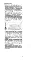
TO LEVEL MOWER
Make sure tires are properly inflated to the
PSI shown on tires. If tires are over or under
inflated, it may affect the appearance of your
lawn and lead you to think the mower is not
adjusted properly,
VISUAL SIDE-TO-SIDE ADJUSTMENT
1. With all tires properly inflated and if your
lawn appears unevenly cut, determine
which side of mower is cutting lower.
NOTE: As desired, you can raise the low
side of mower or lower the high side.
2. Go to side of mower you wish to adjust.
3. With a 3/4" or adjustable wrench, turn
lift link adjustment nut (A) to the left to
lower the mower, or, to the right to raise
the mower.
Turn nut d
to raise mower
4. If adjustment is necessary, see steps 2
and 3 in Visual Adjustment instructions
above.
5. Recheck measurements, adjustif necessary until both sides are equal.
FRONT-TO-BACK ADJUSTMENT
IMPORTANT: Deck must be level sideto-side.
To obtain the best cutting results, the mower
blades should be adjusted so the front tip is
1/8" to I/2" lower than the rear tip when the
mower is in its highest position,
CAUTION: Blades are sharp, Protect
your hands with gloves and!or wrap blade
with heavy cloth.
• Raise mower to highest position.
• Position any blade so the tip is pointing
straight forward, Measure distance (B) to
the ground at front and reartip ofthe blade.
• If front tip of blade is not 1/8" to 1/2" lower
than the rear tip, go to the front of tractor.
• With an 11/16" or adjustable wrench,
loosen jam nut A several turns to clear
adjustment nut B.
• With a 3/4" or adjustable wrench, turn
front link adjustment nut (B) clockwise
(ltighten) to raise the front of mower, or,
counterclockwise (loosen) to lower the
front mower.
Turn nut left
to lower mower
NOTE: Each full turn of adjustment nut will
change mower height about 3/16",
4. Test your adjustment by mowing some
uncut grass and visually checking the
appearance. Readjust, if necessary, until
you are satisfied with the results.
PRECISION SIDE-TO-SIDE ADJUSTMENT
_1 Withalltires properly inflated; parktractor .....................
on level ground or driveway.
CAUTION: Blades are sharp. Protect
your hands with gloves and/or wrap blade
Tighten adjust nut
Loosen adjust
with heavy cloth.
B to raise mower
nut B to lower
2. Raise mower to its highest position.
mower
3. At both sides of mower, position blade at
Loosenjam nut A first
side and measure the distance (A) from
bottom edge of blade to the ground. The
NOTE: Each full turn of the adjustment nut
distanceshould bethesame on bothsides. will change mower height about 1/8".
• Recheck measurements, adjust if necessary until front tip of blade is 1/8" to t/2"
lower than the rear tip.
• Holdadjustment nut inposition with wrench
and tighten jam nut securely against adjustment nut.
27
TO REPLACE
MOWER
DRWE
BELT
MOWER DRIVE BELT REMOVAL
1, Park tractor on a level surface, Engage
parking brake,
2. Lower attachment lift lever to its lowest
position,
3, Disengage belttension rod (K) from lock
bracket (L),
AUT1ON:Belttension rodis spring]oaded, Have afirm grip on rod and release slowly,
4. Remove screws (P) from R.H. and L,H,
mandrel covers and remove covers (Q),
5. Remove any dirtor grass clippings which
may have accumulated around mandrels
and entire upper deck surface,
6. Remove belt from electric clutch pulley
(M),both mandrel pulleys (R) and all idler
pulleys (S).
NOTE: Observe entire motion drive belt
and position of all belt guides and keepers.
2. Disconnect clutch wire harness (A).
3. Remove anti-rotation link (B) on right
side of tractor,
4, Remove belt from stationary idler (C)
and clutching idler (D).
5. Remove belt from centerspan idler (E).
6. Pull belt slack toward rear of tractor.
Carefully remove belt upwards from
transmission input pulley and over cooling fan blades (F),
7. Remove belt downward from engine
pulley and around electric clutch (G).
8, Slide belt toward rear of tractor, off the
steering plate (H) and removefromtractor.
BELT INSTALLATION 1. Install new belt from tractor rear to front,
over the steering plate (H) and above
clutch brake pedal shaft (J),
2. Pull belttoward frontoftractor and roll belt
around electric clutch and onto engine
pulley (G),
3. Pull belt toward rear of tractor, Carefully
work belt down around transmission
cooling fan and onto the input pulley (F).
Be sure belt is inside the belt keeper,
4. Install belt on centerspan idler (E).
5, Install belt through stationary idler (C)
and clutching idler (D),
6. Reinstall anti-rotation link (B) on right
side of tractor. Tighten securely.
7. Reconnect clutch harness (A),
8. Make sure belt is in all pulley grooves
and inside all belt guides and keepers.
9. Install mower (See "TO INSTALL MOWER" in this section of manual).
MOWER DRIVE BELT INSTALLATION
1. Install belt around both mandrel pulleys
(R) and around idler pulleys (S) asshown.
2. Install belt onto electric clutch putley (M),
IMPORTANT: Check beltfor proper routing
in all mower pulley grooves.
3. Reassemble R.H, and L,H. mandrel coy/_
ers (Q). Securely tighten all screws.
I JU:
4. Engage belt tension rod (K) on locking
k,z_' _
.........
bracket (L), ............................................................
&CAUTION: Belttension rodis springload('_
2
ed. Have atightgrip on rodand engage slowly,
_
_/
5, Raise attachment lift lever to highest
_A_
position.
TO REPLACE MOTION DRIVE BELT
Park the tractor on level surface. Engage
parking brake, For assistance, there is a
belt installationguide decal on bottom side
of left footrest.
BELT REMOVAL1. Remove mower (See "TO REMOVE
MOWER" in this section of manual).
28
5#
TO CHECK BRAKE
If tractor requires more than five (5) feet to
stop at highest speed in highest gear on a
level, dry concrete or paved surface, then
brake must be serviced.
You may also check brake by:
1. Park tractor on a level, dry concrete or
paved surface, depress brake pedal all
the way down and engage parking brake.
2. Disengage transmission
by placing
freewheel control in "transmission disengaged" position. Pull freewheel control
out and into the slot and release so it is
held in the disengaged position.
The rear wheels must lock and skid when
you tryto manually push the tractor forward.
If the rear wheels rotate, then the brake
needs to be serviced. Contact a Sears or
other qualified service center.
FRONT WHEEL TOE-IN/CAMBER
Your new tractor front wheel toe-in and camber is set at the factory and is normal. The
front wheeltoe-in and camber are not adjustable. If damage has occurred to affect the
factory set front wheel toe-in or camber, contact a Sears or other qualified service center.
TO REMOVE WHEEL FOR REPAIRS
1. Block up axle securely,
2. Remove axle cover, retaining ring and
washers to allow wheel removal (rear
wheels have a square key- Do not lose).
3. Repair tire and reassemble.
NOTE: On rearwheels only: aligngrooves in
rear wheel hub and axle. Insert square key.
4. Replace washers and snap retaining ring
securely in axle groove.
5, Replace axle cover.
NOTE: To seal tire punctures and prevent
flat tires due to slow leaks, purchase and
us#tire seatant from Sears. Tire sealant also
prevents tire dry rot and corrosion,
TO START ENGINE WITH A WEAK BATTERY
_I_WARNING: Lead-acid batteries generate explosive gases. Keep sparks, flame
and smoking materials away from batteries.
Always wear eye protection when around
batteries.
Ifyour battery is too weak to start the engine,
it should be recharged. (See "BATIERY" in
the MAINTENANCE section of this manual).
If "jumper cables" are used for emergency
starting, follow this procedure:
IMPORTANT: Your tractor is equipped with
a 12 volt system. The othervehicle must also
be a 12 volt system. Do not use your tractor
battery to start other vehicles.
TO ATTACH JUMPER CABLES
1. Connect one end ofthe RED cableto the
POSITIVE (+) terminal of each battery(AB),taking care notto short against tractor
chassis.
2. Connect one end of the BLACK cable
to the NEGATIVE (-)terminal (C) of fully
charged battery.
3, Connect the other end of the BLACK
cable (D) to good chassis ground, away
from fuel tank and battery.
TO REMOVE CABLES, REVERSE ORDER
1. BLACK cablefirst from chassis and then
from the fully charged battery,
2. RED cable last from both batteries.
Weak #[.Dead
Battery
Washers
Retaining
Ring
I
Axle Cover
_Square
Key (Rear
Wheel Only)
29
Ful!y Charg_td
Battery
REPLACING BATTERY
TO REMOVE
HOOD AND GRILL ASSEMBLY
1. Raise hood.
2. Unsnap headlight wire connector.
3, Stand in front of tractor. Grasp hood at
sides, tilt toward engine and lift off of
tractor.
4. When replacing hood, be sureto reconnect the headlight wire connector.
n_asWARNING: Do not short battery termiby allowing awrench or anyother object
to contact both terminals at the same time.
Before connecting battery, remove metal
bracelets, wristwatch bands, rings, etc.
Positive terminal must be connected first to
preventsparking from accidental grounding.
1. Lift hood to raised position.
2. Remove terminal cover.
3. Disconnect BLACK battery cable then
RED battery cable and carefully remove
battery from tractor.
4. Install new battery with terminals insame
position as old battery.
5. Reinstall terminal cover.
6. First connect RED battery cable to positive (+) battery terminal with bolt and nut
as shown. Tighten securely.
7. Connect BLACK grounding cable to
negative (-) battery terminal with remaining bolt and nuL Tighten securely
8. Close hood.
Hood
Headlight Wire
Connector-
TRANSMISSION
REMOVAL/REPLACEMENT
Should yourtransmission require removalfor
service or replacement, it should be purged
after reinstallation and before operating the
tractor. See "PURGE TRANSMISSION" in
the Operation section of this manual,
ENGINE
TO ADJUST THROTTLE CONTROL
CABLE
The throttle control has been preset at
the factory and adjustment should not be
TO REPLACE
HEADLIGHT BULB
necessary Check adjustment as described
1. Raise hood.
below before loosening cable. If adjustment
2. Remove bulb hotder from the hole in the
is necessary, see engine manual.
backside of the grill.
TO ADJUST CHOKE CONTROl.
3: Replace bulb inholder and install bulb .......
The choke controi
been preset at
holder securely back into the hole inthe
the factory and adjustment should not be
backside of the grill.
necessary. If adjustment is necessary, see
4. Close hood,
engine manual,
INTERLOCKS AND RELAYS
TO ADJUST CARBURETOR
Loose or damaged wiring may cause your
Your carburetor has been preset at the factory
tractor to run poorly,stop running, or prevent
and adjustment should not be necessary.
it from starting,
However, minor adjustment may be required
° Check wiring.
to compensate for differences in fuel, temTO REPLACE FUSE
perature, altitude or load. If the engine does
Replace with30 amp automotive-type plugneed adjustment, see engine manual.
in fuse. The fuse holder is located behind
the dash.
3O
ENGINE
FUEL SYSTEM
IMPORTANT: It is important to prevent
gum deposits from forming in essential fuel
system parts such as carburetor, fuel hose,
or tank duringstorage, A[so, alcohol blended
fuels (called gasohol or using ethanol or
methanol) can attract moisture which leads
to separation and formation of acids during
storage. Acidic gas can damage the fuel
system of an engine while in storage.
• Empty the fuel tank by starting the engine
and letting it run until the fuel lines and
carburetor are empty.
• Never use engine or carburetor cleaner
products in the fuel tank or permanent
damage may occur.
• Use fresh fuel next season.
NOTE: Fuel stabilizer is an acceptable alternative in minimizing the formation of fuel
gum deposits during storage. Add stabilizer
to gasoline in fuel tank or storage container.
Always followthe mix ratio found on stabilizer
container. Run engine at least 10 minutes
after adding stabilizer to allowthestabilizerto
reach the carburetor. Do not empty the gas
tank and carburetor if using fuel stabilizer.
ENGINE OIL
Drain oil (with engine warm) and replace
with clean engine oil. (See"ENGINE" inthe
Maintenance section of this manual),
BATTERY
CYLINDER(S)
• Fully charge the battery for storage.
1. Remove spark plug(s).
• After a period of time in storage, battery
2. Pour one ounce of oil through spark plug
may require recharging.
hole(s) into cylinder(s).
• To help prevent corrosion and power leak3. Turn ignition key to "START" position for
age during long periods of storage, battery
a few seconds to distribute oil.
cables should be disconnected and bat4. Replace with new spark plug(s).
tery cleaned thoroughly (see "TO CLEAN
BATTERY AND TERMINALS" in the
OTHER
Maintenance section of this-manual): ...............
. uo......
,. .
not store gasol=neTromone
season to
o Aftercleaning, leave cables disconnected
another.
, and place cables where they cannot come
- Replaceyourgasoline can ifyourcan starts
in contact with battery terminals.
to rust. Rust and/or dirt in your gasoline
• if battery is removed from tractor for
will cause prob]ems.
storage, do not store battery directly on
• If possible, store your tractor indoorsand
concrete or damp surfaces.
coveritto give protection from dust and dirt,
• Cover your tractor with a suitable protective cover that does not retain moisture,
Do not use plastic. Plastic cannot breathe
which allows condensation to form andwill
cause your tractor to rust.
IMPORTANT:
Never cover tractor while
engine and exhaust areas are still warm,
Immediately prepare yourtractorfor storage
at the end of the season or if the tractor will
not be used for 30 days or more.
_IbWARNING" Never store the tractor with
gasoline in the tank inside a building where
fumes may reach an open flame or spark,
Allow the engine to cool before storing in
any enclosure.
TRACTOR
Remove mower from tractor for winter
storage. When mower is to be stored for a
period of time, clean it thoroughly, remove
all dirt, grease, leaves, etc. Store in a clean,
dry area.
1. Clean entire tractor (See "CLEANING"
in the Maintenance section of this
manual),
2. Inspect and replace belts, if necessary
(See belt replacement instructions in the
Service and Adjustments section of this
manual).
3. Lubricate as shown in the Maintenance
section of this manual,
4, Be sure that all nuts, bolts and screws
are securely fastened, Inspect moving
parts for damage, breakage and wear.
Replace if necessary.
5. Touch up all rusted or chipped paint
surfaces; sand lightly before painting,
31
TROUBLESHOOTING CHART:
See appropriate section in manual unless directed to Sears service center
PROBLEM
CAUSE
CORRECTION
,,, ,,
Will not start
i"'"
OutoffueI.
1
Fill fuel tank.
2
Engine not "CHOKED"
2
See "TO START ENGINE" in
Operation section.
3
Engine flooded.
3
Wait several minutes before
attempting to start.
4
Bad spark plug.
4
Replace spark plug.
5
Dirty air filter.
5
Clean!replace
Engine will not
turn over
......................................
properly.
air filter.
6
Dirty fuel filter.
6
Replace fuel filter.
7
Water in fuel.
7
Empty fuel tank and carburetor,
refill tank with fresh gasoline and
replace fuel filter.
8
Loose or damaged wiring.
8
Check all wiring.
9
Carburetor
9
See "To Adjust Carburetor" in
Service and Adiustments section.
,10
Con!act a Bears or other qualified
serv=ce center,
10
Hard to start'
"
.......
out of adjustment.
Engine valves out of adjustment.
1
Dirty air filter.
1
Clean/replace
2
Bad spark plug.
2
Replace spark plug.
3
'Weak or dead battery_
3 r Recharge or replace battery.
4
Dirty fuel filter.
4
Replace fuel filter.
5
Stale or dirty fuel.
5
Empty fuel tank and refill tank with
fresh, clean gasoline.
6
Loose or damaged wiring,
6
Check all wiring.
7
Carburetor
7
See "To Adjust Carburetor" in
Service and Adjustments section.
8
Engine valves out of adjustment.
8
Contact a Sears or other qualified
service center.
1
Depress clutch/brake
2
Disengage
out of adjustment.
pedal not depressed.
air filter.
1
Clutch!brake
2
Attachment
3
Weak or dead battery.
3
4
Blown fuse: ......................................
4
Replace
5
Corroded battery terminals.
5
Clean battery terminals.
6
Loose or damaged wiring.
6
Check all wiring.
7
Faulty ignffion switch.
7
Check/replace
ignition switch.
8
Faulty solenoid or starter.
;8
Check/replace
solenoid
9
Faulty operator presence
switch(us).
9
1
Weak or dead battery,
1 i Recharge or replace battery.
2
Corroded battery terminals.
2
Clean battery terminals.
3
Loose or damaged wiring.
3
Check at] wiring.
4
Faully solenoid or starter.
4
Check/replace
clutch is engaged.
pedal.
attachment
clutch.
Recharge or replace battery.
fuse: ..................................
or starter
Contact a Sears or other qualified
service center.
,,,,,,
Engine clicks but
will not start
32
solenoid or starter.
TROUBLESHOOTING CHART:
See appropriate section in manual unless directed to Sears service center
PROBLEM
CAUSE
Loss of power
Excessive vibration
CORRECTION
1
Cutting too much grass/too fast,
1
Raise cutting height/reduce
2
Throttle in "CHOKE"
position.
2
Adjust throttle control.
3
Build-up of grass, leaves and
trash under mower,
3
Clean underside
housing.
4
Dirty air filter.
4
Clean/replace
5
Low oil level/dirty oil.
S
Check oil lever/change oil.
6
Faufty spark plug,
6
Ctean®aporchangesparkplug
7
Dirty fuel filter.
7
Replace fuel filter.
8
Stale or dirty fuel,
8
Empty fuel tank and refill tank wit]'
fresh, clean gasoline.
9
Water in fuel.
9
Empty fuel tank and carburetor,
refill tank with fresh gasoline and
replace rue] filter.
10
Spark plug wire loose.
10
Connect & tighten spark plug wire
tl
Dirty engine air screen/fins.
11
Clean engine air screen/fins.
12
Dirty/clogged
12
Clean/replace
13
Loose or damaged wiring.
13
Chock all wiring.
14
Carburetor0ut
14
See "To Adjust Carburetor" in
Service and Adjustments section,
15
Engine valves out of adjustment.
15
Contact a Sears or other qualified
service contor.
muffler.
of adjustment.
air filter.
muffler.
1
Worn, bent or loose b]ade,
1
Replace blade, Tighten blade bolt
Bent blade mandrel.
2
Contact a Sears or other qualified
service center.
3
Loose/damaged
3
Tighten loose part(s).
Replaco damaged parts.
1
Faulty operator-safety
control system.
1
Check wiring, switches and
connections. If not corrected,
contact a Sears or other
1
Replace bfade. Tighten blade bolt
part(s).
presence
Poor cut - uneven
1
Worn, bent or loose blade.
cutting ...................................
will
of mower
2
run when operator
leaves seat with attachment clutchengaged
Mower blades
not rotate
speed
2
Mower deck not level
..................... 2
3
Buildup of grass, leaves, and
trash under mower.
3
Clean underside
housing.
4
Bent blade mandrel.
4
Contact a Sears or other
qualified service center.
5
Clogged mower deck vent from
build-up of grass, leaves, and
trash around mandre}s.
5
Clean around mandrels to
open vent holes.
1
Obstruction
1
Remove obstruction.
2
Worn/damaged
3
Frozen idler pulley.
3
Replace idler pulley.
4
Frozen blade mandrel.
4
Contact a Sears or other
qualified service center.
in clutch mechanism.
mower drive belt, 2
33
revel mower deck_ ...........................
of mower
Replace mower drive belt.
TROUBLESHOOTING CHART:
See appropriate section in manual unless directed to Sears service center
PROBLEM
CAUSE
Poor grass
discharge
Engine speed too slow.
1
Place thro_tle control in "FAST"
position.
2
Travel speed too fast.
2
Shift to slower speed.
3
Wet grass.
3
Allow grass to dry before mowing.
4
Mower deck not Ievel.
4
Level mower deck.
5
Low/uneven
5
Check tires for proper PSi.
6
Worn, bent or loose blade.
6
Replace/sharpen
blade bolt.
7
Buildup of grass, leaves and
trash under mower,
7
Clean underside of mower
housing.
8
Mower drive belt worn.
8
Replace mower drive belt.
9
Blades improperly
9
Reinstal[ blades sharp edge down.
10
Replace with blades listed in
this manual.
tire air pressure.
installed.
blades used.
blade. Tighten
Improper
11
Clogged mower deckvent holes
11 Clean around mandrels to
from buildup of grass, leaves, and
open vent holes.
trash around mandrels.
Battery will not
charge
1
Light switch is "OFF".
1
2
Bulb(s) or lamp(s)
2
Replace bulb(s) or tamp(s).
3
Faulty light switch.
3
Check/replace
4
Loose or damaged wiring.
4
Check wiring and connections.
5
Blown fuse.
5
Replace fuse.
burned out.
Turn light switch "ON".
{ight switch.
1
Bad battery ceil(s).
1
Replace battery.
2
Poor cable connections.
2
Checkjciean
3
Faulty regulator
3
Replace regulator.
4
Faulty alternator.
1
Freewheel controi in
"DISENGAGED"
position,
2
Debris on steering
equipped),
3
(if so equipped).
all connections.
4
Replace altematoro
1
P[ace freewheel control in
"ENGAGED" position,
2
See "CLEANING" in the
maintenance section,
Motion drive belt worn. damaged.
or broken.
3
Replace motion drive belt.
!4
Air trapped in transmission during
shipment or servicing.
4
Purge transmission.
i 5
Axle key missing.
5
Install axle key at rear wheel. See
"TO REMOVE WHEEL" in the
Service and Adjustments section.
il
Engine
throttle control not set 1
between half and full speed {fast)
position before stopping engine,
Move throttle controlbetween
half and full speed (fast) position
before stopping engine.
Reverse operation system (ROS)
is not "ON" while mower or other
attachment is engaged.
Turn ignition key to RO8 "ON"
position. See Operation seclion.
Loss of drive
Engine dies when
tractor is shiffea
into reverse
1
10
Headlight(s) not
working
(if so equipped)
Engine "backfires"
when turning
engine "OFF"
CORRECTION
1
......
plate (if
34
1
NEED MORE HELP?
You'l_ find the answer and mo_e on managemyhome.com
• Find this and a[[ your other product manuals on[ine.
• Get answers from our team of home experts,
• Get a personalized maintenance plan for your home.
• Find information and tools to help with home projects.
35
- for free!
0i
SUGGESTED
GUIDE FOR SIGHTING SLOPES FOR SAFE OPERATION
ONLY RIDE UP AND DOWN HILL,
NOT ACROSS HILL
15 DEGREES
MAX.
t
down the face of slopes, never across the face, Do not mow
WARNING: To avoid serious injury, operate your tractor up and
slopes greater than 15 degrees. Make turns gradually to prevent
tipping or toss of control. Exercise extreme caution when
changing direction on slopes.
1, Fold this page along dotted line indicated above.
2, Hold page before you so that its [eft edge is vertically paraf|el to a tree
trunk or other upright structure.
3, Sight across the fold in the direction of hill slope you want to measure,
4. Compare the angle of the fold with the slope of the hill
GarantJa..........................................................
Reglas de Segurldad ......................................
Especificaciones del Producto ........................
Montaje/Pre Operaci6n ...................................
Operaci6n .......................................................
Mantenimiento ................................................
GarantJa para equipos
GARANTIA COMPLETA
tractores
37
38
41
43
48
56
Programa de Mantenimiento .......................... 56
Ser_icio y Ajustes ........................................... 61
Almacenamiento ............................................. 66
IdentificacJ6n de Problemas ........................... 67
ServiciO Sears ............................. Contraportada
Craftsman
DE CRAFTS
MAN
POR DOS A_IOS desde Ia fecha de compra, todas las partes no sustituibles de este equipo tractor estan
garantizadas contra cua[quier defecto de material o mano de obra, Una parle no sustituible defectuosa
recibir_ reparaci6n o reemplazo gratuite en casa si ta reparaci6n es imposible.
POR CINCO ACJOS desde la fecha de compra, el bastJdor y el eje delantero de este equipo tractor est_n
garantizados contra cualquier defecto de material o mano de obra. Un bastidor o eje delantero defectuoso
recibir& reparaci6n o reemplazo gratuito en casa si la reparaciSn es imposibIe.
DURANTE 90 DiAS deeds la fecha de compra, la bateria (una parte sustituible) de este equipo tractor
esi#, garantizada contra cualquier defecto de material o mano de obra (nuestra prueba comprueba que no
contendr& carga). Una bateria defectuosa recibir_ un reemplazo gratuito en casa.
GARANTiA UMITADA
DE POR VIDA ADICIONAL en el EJE DELANTERO DE HIERRO COLADO (sl
est_ provisto)
DURANTE EL TIEMPO EN QUE SE USE por el propieta_io original despu_s del quinto a_o a partir de Ia
fecha de compra, e[ eje delantero de hierro colado (si est_ provisto) de este equipo tractos est& gamntizado
contra cualquier defecto de material o mano de obra. Con el comprobante de compra, un eje delantero de
hierro colado recibir_, un reemplazo gratuito en casa.
SERVICIO
DE GARANTiA
Para conocer los detalles de la cober_ura de garantia para obtener una reparaci6n
llame al 1-800-659-59I 7 6 visite el sitio web: www. craftsman.corn
En todos los casos anteriores, si el reemplazo
el mismo modelo o uno equivalente.
es imposible,
o reemp]azo
el equipo tractor ser_. sustituido
gratuito,
sin cargo con
Toda la cobertura de garantia anterior ser_, nula si este equipo tractor se utiliza alguna vez para bdndar
servicios comerciales o si se alquila a otra persona.
Esta garantJa cubre 0NICAMENTE
defectos de material y mano de obra, La cobertura de garantia
N O incluye:
•
Partes sustituibles (excepto la bateria) que se puedan desgastar por el uso normal dentro del periodo de
garantia incluso, pero sin Iimitarse a, cuchillas, bujias, filtros de aire, correas y filtros de aceite.
• Servicios de mantenimiento est_ndar, cambios de aceite o afinaciones.
•
Reemplazo o reparaci6n de neum_ticos por pinchazos causados por objetos externos como clavos,
espinas, tocones o vidrios.
• Reemplazo o reparaci6n de neum&ticos o ruedas por desgaste normal, accidentes o por operaci6n o
.............
mantenimi_nto incorrectos ......................................................................................
• Reparaciones necesarias por abuso del operador incluso, pero sin limitarse a, daiSos causados por
ramolcar objetos qua superen la capacidad del equipo tractor, chocar contra objetos qua doblen el
bastidor' el ensamble det eje o eI cig0efial o sobrepasar Ia velocidad deI motor.
• Repa_a_i_nesnecesariasp_rne_i_enciade_perad_r_inc_us_(per_sin_imitarseae_)da_se_ctric_s
y mec&nicos causados per e[ almacenamiento
incorrecto, por no usar el grado y la cantidad correctos de
aceite de motor, por no mantener del muelle libra de residuos inflamables o por no mantener el equipo
tractor de acuerdo con las instrucciones qua contiene el manual del operador.
• Limpieza o reparaciones
del motor (sistema de combustible)
cuando se determina que se us6
combustible contaminado y oxidado (sarro). En general, el combustible debe usarse dentro de los 30
dias posteriores a su compra,
• Deterioro y desgaste normal de los acabados exteriores o sustituci6n de r6tutos de productos.
Esta garantla le otorga derechos legales especfficos, y usted tambi6n puede tenet otros derechos que
varian de un estado a otto.
Sears Brands Management Corporation, Hoffman Estates, IL 60179
37
_LPELIGRO: Esta Maquina cortadorg es capaz de amputar las manosy los pies y de ianzgr
objetos, si no se observgn lag instrucciones de seguridgd siguientes se pueden producir
lesiones graves o la muerte.
• No maneje la m&quina si no tiene Ia trampa
_,DVERTENCIA:
Siempre desconecte el alampara c_sped completa, lacanaleta de descarga
brg de la bujia y p6ngalo donde no pueda entrar
u otros dispositivos de seguridad en su lugar
en contacto con Ia bujia, para evitar el arranque
yen funcionamiento.
por acoidente, durante la preparaci6n, el trans• Ralentizar antes de girar.
porte, el ajuste o cuando se hacen reparaciones.
• Nunca dejar una m&quina encendida sin vigi_,DVERTENCIA:
Noavance cuestaabajoa punlancia. Apagar siempre Ias cuchillas, poner el
to muerto ya que podriaperderelcontroldel tractor.
freno de estacionamiento, parar el motor, y
_ADVERTENCIA:
Remolque solamente Jos
quitar Ias Ilaves antes de bajar,
accesorios recomendados y conformes a las
• Desenganche Ias hojas cuando no est6 caftancaracteristicas indicadas por el fabricante de su
do c_sped. Apague el motor y espere hasta que
tractor, Tenga cuidadg y prudencia al utilizar el
todas las partes se detengan par completo antractor. Cuando se encuentre en un declive, oper
tes de limpiarla m&quina, retirar latrampa para
utilizando exclusivamente la velocidad m_.sbaja.
c_sped o destapar la canaleta de descarga.
En caso de un decl]ve una carga excesiva PO- Hacer funcionar la m&quina s6[o con Ia IuzdeI
dria resultar peligrosa. Los neum&ticos pueden
dig o Iuz artificial buena,
perder Ia tracci6n con el suelo y hacerle perder
• No hacer funcionar ta m_.quina estando bajo
el control de su tractor.
los efectos de alcohol o droga.
_bADVERTENGIA: El tuba de escape del motor,
• Poner atenci6n aI tr&fico cuando se opera
cerca de calles o se cruzan.
atgunes de sus constituyentes y algunos componentes deI veh_culo contienen o desprenden
• Poner la maxima atenci6n aI cargar o descarproductos qufm]cos conocidos en el Estado de
gar Ia m&quina en una caravana o cami6n.
California coma causa de c&ncer y defectos al
• Uevar siempre galas de protecci6n cuando se
nacimiento u otros daSos reproductivos.
hace funcionar Ia m&quina,
_DVERTENO!A:
Los barnes, terminales y ac- Los datos indicanque 1as operadores a partir
de los 60 a5os est&n afectados par un gran
cesorios relatives de la baterfa contienen plomo
porcentajede heridas relativas a Ia conducci6n
o compuestos de plomo, productos quimicos
conocidos en el Estado de Califomia coma causa
del cortac_sped. Estos operadores tendrian
que evaluar su habifidad de hacer funcionar
de c&ncer y defectos al nacimiento u otros daSos
el cortac_sped de modo Io bastante seguro
reproductivos. Lavgr las mgnos despu6s de
para proteger a sl mismos y a otras personas
mgnipulartos.
de heridas graves,
I. FUNCIONAMIENTO
GENERAL
• Seguir las recomendaciones deI fabricante
•Leer, entenderyseguirtodaslasinstrucciones
para los pesos y contrapesos de las ruedas.
sabre la m&quina yen el manual antes de
• Mantener la m_.quina libre de hierba, hojas u
empezar,
arras escombros que pueden toear el tuba de
• No poner las manos o los pies cerca de partes
escape/partes del motor calientes y quemarse.
giratorias o debajo de Ia m&quina, mantener
No permitir que el puente del cortac_sped
siempre limpia la abertura de descarga.
cargue hojas u otros residuos que pueden
Permitir el funcionamiento de la m&qu!na s6!o .........causar acumulac!ones_ Limp!at toda salp!_a dura de aceite o carburante antes de hacer
.......a- aduit6s=que tengan farnilia_'idad con las
instrucciones.
operaciones sabre ]a m&quina o guardarla.
Dejarla enfriar antes de guardarla,
, Limpiar el ,_rea de objetos coma piedras,
juguetes, cables, etc, que pueden ser recogiII. FUNCIONAMIENTO
EN PENDIENTES
dos y disparados con las cuchillas.
Lgs pendientes son el mayor factor de accidentes
• Asegurarse de que el _,rea est@libre de otras
relativos a ia perdida de control y vuelco, que
personas antes de poneda en marcha. Parar
pueden causar severas heddas o muerte. El funla m&quina si alguien entra en el _.rea.
cionamiento en pendientes requiere una gtenci6n
• Nunca ]levar pasajeros.
extra. Si no es posible hacer marcha atr_s en una
° No cortar mareha atr&s al no ser absolupendiente o si te sientes incomodo, no la cortes,
tamente necesario. Mirar siempre abajo y
• Cortar hacia arriba y abajo de una pendiente,
detante mientras se procede atr&s.
no de modo horizontal,
• Nunca dirigir el matedal descargado hacia na• Poner atenciones a los hoyos, las raices, los
die. Evitar descargar material contra paredes
bultos, las piedras u otros objetes escondidos.
u obstrucciones. El material podria rebotar
El terreno irregular puede volcar la m&quina.
hacia el operador. Parar las cuchillas cuando
La hierba alta puede esconder obst&culos,
se pasan superficies de grava.
38
• Escoger une velocidad de marcha baja de
mode que no sea necesario pararse o cambiar
estando en una pendiente.
• No corter la hierba mojada. Las nJedas pueden
perder tracci6n.
Poner siempre una marcha cuendo se estA
en pendientes. No poner en punto muerto e ir
cueste abajo.
- Evitar arrancar, perarse o giraren una pendiente. Si Ias ruedas pierden tracci6n, desconectar
las cuchiltas y preceder despacio cuesta abejo
en la pendiente.
• Mantener rode los movimientos en Ins pendientes lentos y gradual. No hacer cambios
repentinos de velocidad o direcci6n, ya que
pueden causer el escape de ta mAquine.
• Poner la m&xima etenci6n cuando Ia m&quina
funciona con captadores de hierba u otros
dispositivos enganchedos; pueden afecter la
estabilided de la m&quina. No usar en pendientes empinados.
° No intentar estabilizar Ia m&quina poniendo el
pie en el terreno.
, No cortar cerca de bajadas, cunetes y orillas.
Las m&quine puede volcarse improviSamente
si una rueda est& en et borde o se hunde.
II!. NIl(lOS
• Tener eI m_imo cuidado cuando se acerca
a cantos ciegos, arbustos, Arboles u otros
objetos que pueden impedir Ia vista de niSos.
IV. REMOLQUE
• Remolcar s61ocon una m&quina que tenga un
gancho disefiado pare remolcar. Enganchar el
equipo o remolcar s61o en el punto dispuesto
al efecto.
• Seguir las recomendaciones del productor con
respecto a los Iimites del equipo per remolcar
y el remolque en pendientes.
• Nunce permitir que nifios u otras personas
est6n dentro del equipo per remolcar.
• En pendientes, el peso del equipo remotcado
puede causer la p@rdidade tracciSn y la p@rdida de control.
• Viajar despacio y dejar mAs distancia pare
frenar.
V, SERVICIO
MANIPULACION SEGURA DE LA GASOLINA
Pare evitar heridas personales o defies ales
cosas, porter et mAximo cuidedo ala hera de
manipular la gasoline. La gasoline es extremamente inflameble y los vapores son explosives.
° Apagar redes los cigardllos, cigarros, pipas y
otras fuentes de ignici6n.
• Usar s61ocontenedores pare gasolina aprobados.
_ADVERTENCIA:
LOS NI_'4OS PUEDEN
SUFRIR DANES CON EL use DE ESTE EQUIPC. La Academia Estadounidense de Pediatria
• Nunca quitar el tap6n de la gasoIina o afiadir
(American Academy of Pediatrics) recomienda
carburante con el motor en marcha, dejar
enfriar el motor antes del abastecimiento de
que s61o se permita aniSos con una edad minima de 12 aries manejar m&quinas cortec_sped
la gasolina.
manuales, y al menos de 16 aries para manejar
° Nunca abastecer la m&quina al interior de un
tractores cortac@sped.
local
Si el operador no pone atenci6n ata presencia
• Nunca guarder ]a mdquina o el contenedor
de los nifios pueden ocurrir accidentes tr&gicos.
del carburante deride haya una llama abierta,
chispas o una Iuz piloto come un calentador
Los nir_os a menudo est_n atraldos per la m&quide agua u otros dispositivos.
nay Ins actividad de cortar. No dar per hecho
• Nunca Ilener Ios contenedores aI interior de
de que los nifios se queden edonde estaban la
un vehiculo o en una caravena o cami6n
01timevez que los vistes.
...........
__ Mantener los nifios fuera de &rea de €orte y .............
re.cubiertos con un forte de pl&stico. Cotocar
vigi{ados per un adulto responsable que no sea
mempre loscontenedores en el terreno Iejos
del vehiculo cuando se est& flenando.
el operador.
• Quiter el equipo de gas det cami6n o caravana
• Ester alerta y apegar Ia maquina si un nifios
y abastecerto en el terreno. Si no es posibie,
entre en el Area.
abastecer d[cho equipo con un contenedor por. Antes y durante la marcha atrAs, mirar adelante
t&tiI, mAs bien que de un surtidor de gasolina.
y abajo para vet si hay nifios pequeSos.
• Mantener la boquflta a contacto de] borde
• Nunca Hever nifios, incluso si hay Ins cuchillas
del dep6s_to de carburante ota abertura del
apagadas. Podrian caer y herirse seriemente
contenedor durante toda la operaci6n de
o interferir con el funcionamiento seguro de la
abastecimiento. No utilizar un dispositivo con
maquina, los niSos que se hart Ilevado precboquilla cerrada-abierta,
edentemente pueden aparecer de pronto en el
• Si se vierte carburante sobre la ropa, cambiArea de corte per otro paseo y ser atropellados
arse Ia ropa inmediatamente.
o tumbados per la m_.quina.
• Nunce flenar el dep6sito m#,s de Io debido.
• Nunca dejar que los nifios manipulen fa mAVolver a celocar el tap6n del gas y cerrar de
quina.
mode firme.
39
OPERACIONES DE SERVICIO GENERALES
• Nunca haeer funcionar la m&quina en un _,rea
cerrada.
• Mantenertodas las t_Jercasy pemos apretados
para asegurarse de que trabaja en condiciones
seguras.
, Nunca modificar los dispositivos de seguridad.
Controlar su correcto funcionamienta regularmente,
, Mantener la m&quina libre de hierba, hojas
u otros residues acumutados. Limpiar las
salpicaduras de aceite o carburante y quitar
cualquier eosa mojada con carburante. Dejar
que la m&quina se enfrie antes de guardarla.
• Si se golpea un objeto ajeno, hay que pararse
e inspeccionar Ia m_,quina. Reparar, si es
necesario, antes de volver a porter en marcha.
• Nunca hacer ning_n ajuste o reparaci6n con
el motor en funci6n.
• Verifique los componentes de la trampa para
c_sped y la canaleta de descarga con frecuencia y sustituya con repuestos recomendados
par el fabricante cuando sea necesario.
• Las cuchiilas de[ cortac_sped son afiladas.
Envolver la cuchilla, ponerse guantes y poner
la m&xima atenci6n cuando se hacen operaciones en elias.
,
• Estar alerta y apagar la m&quina si un niSos
antra en el &rea.
Controlar el funcionamiento deI freno frecuentemente. Ajustar y hacer las operaciones de
mantenimiento cuando eso sea necesario.
• Antes y durante ]a marcha atr&s, mirar adelante
y abajo para vet si hay niflos pequer_os.
• Mantener y sustituir las etiquetas de seguridad
e instrucci6n, cuando sea necesario.
• Cortar hacia arriba y abajo de una pendiente
(t 5° M_), no de mode horizontal.
• Asegurarse de que el &tea est@libre de arras
personas antes de ponerla en marcha, para la
- Escoger una velocidad de marcha baja de
m_quina si alguien entra en el &rea.
mode que no sea necesario pararse o cambiar
estando en una pendiente.
• Nunca Uevar pasajeros.
• Evitar arrancar, pararse o girar en una pendien• No cortar marcha atr&sal no ser absolutamente
re. Si Ias ruedas pierden tracci6n, desconectar
necesario. Mirar siempre abajo y delante
las cuchillas y preceder despacio cuesta abajo
mientras se precede atr&s.
en la pendiente.
• Nunca Ilevar nifios, incluso si hay las cuohillas
• Si la m&quina se para mientras va cuesta
apagadas. Podrian caer y herirse seriamente
arriba, desconectar las cuchillas, poner la
o interferir con el funcionamiento seguro de la
marcha atr_s y ir hacia atr&s despacio.
m&quina, los nifios que so han llevado precedentemente pueden aparecer de pronto en el
• No girar estando en pendientes si no es nece&rea de carte par otro paseo y ser atropellados
sario, y luego girar despacio y gradualmente
o tumbados par la m_quina.
cuesta abajo, si es posible.
-•--Mantener-los nifios fuera deI &rea-de carte y .........
• --AI cargar o descargar lam_.quina; no sobrepase ...........
vigilados per un adulto responsable que no sea
et &ngulo maxima recomendado de 15°,
el operador.
4O
ESPECIFICACIONES
DEL
PRODUCTO
Capacidad y Tipo
de Gasoline:
3 Calories/t1.35
L
Regular Sin Plomo
Tipo de Aceite
{API: SG-SL):
SAE 10W30 (sobre 32°F/0°C
SAE5W30(deabajo32°FiO°C
Capacidad
Aceite:
64 OzJ1,96 L
de
Bujfa
Champion RC12YC
(Abertura: .030"/0.76
Sistemade Carga:
15 Amps @3600 RPM
Baterla:
AmpiHr:
Min, CCA:
Modelo TamaP,o:
Torsi6n deI Perno
de la Cuchilla:
45-55 Ft. LbsJ
62-75 Nm
ram)
28
230
U1R
FELICITACIONES por la compm de su tractor,Ha
sido diseSado, p]anificado yfabricadopare darle Ia
mejor conliabilidad y el mejor rendimiento posibie.
En el caeo de que se encuentre con cua[quier
problema que no pueda solucionar _ci{mente,
haga el favor de ponerse en contacto con un
centro de servicioSears o con un otro centro de
servicJo cuaIiffcado. Ouenta con representantes
bien capacitados y competentes y con las herramientas adecuadas para darle servicio o para
reparar este tractor.
Haga el favor de leer y de guardar este manual.
Estas instruc-ci0nes te permitir&n montar y mantenet su unidad en forma adecuada. Siempre
observe/as "REGLAS DE SEGUR/DAD."
RESPONSABILIDADES
DEL CLIENTE
• Lea y observe las reglas de seguridad.
• Siga un programa regular de mantenimiento,
cuidado y ueo de su tractor.
• Siga las instrucciones descritas en las secciones "Mantenimiento" y '_,lmacenamiento"
de este manual
En el estado de California, la toy exige Io anterior
(Secci6n 4442 deI "California Public Resources
Code"). Otros estados pueden contar con otras
[eyes parecidas. Las teyes federales se aplican
en latierras federates. Su centre de Servicio m_s
cercano tiene disponible amortiguadores de oh(spas para el silenciador, (Vea [a secci6n de Partes
de Repuesto en el manual Ingl@sdel dueSo.)
ACUERDOS
DE PROTECClON
PARA
LA REPARACION
Congratutaciones per su buena compra. Su
nuevo producto Craftsman® est& disefado y
fabricado para funcionar de mode fiable per
muchos aSos. Pore come todos los productos,
puede necesitar alguna reparaci6n de tanto en
tanto. En este case tenet un Acuerdo de Protecci6n para la Reparaci6n puede hacedes ahorrar
dinero y fastidios.
Compre ahora un Acuerdo de Protecci6n para la
Reparaci6n y prot6gese de molestias y gastos
inesperados.
Un Acuerdo inctuye los puntos siguientes:
• $ervicio experto de nuestros 12.000 especia}istasprofesionales en Ia reparaci6n.
• Servicio ilimitado sin cargo alguno para
laspartes y Ia mane de obra sobre todas las
reparaciones garantizadas.
• Sustftuc{6n dei produoto si su producto
garantizado no puede set arreglado.
• Descuento de110% sobre el precio corriente
dei servicio y de }aspartes relativas a_servicio
no cubiertas pot el acuerdo; tambi_n el 10%
menos sobre el precio corriente de un control
de mantenimiento preventivo.
• Ayuda r_pida portel6fono-soporte telef6nico por parte de un representante Sears sobre
productosque requieren un arreglo en casa, y
adem_.s una programaci6n sobre los arreglos
m&s convenientes.
Cuando se ha comprado el Acuerdo, basta con
• Utilice prendas de seguridad adeeuadas al
una Ilamada telef6nica para programar el servtcio.
manejar Ia m&quina, incluidos (come minimo)
Puede Ilamar cuando quiera, diay noche o fijar
calzado de seguridad, gafas protectoras y proen linea una cita para obtener el servicio. Sears
tecci6n auditiva. No utitice pantalones cortes
tiene m&s de 12.000 especialistas profesionaLes
y/o catzado abierto coando corte la hierba.
en la reparaci6n, que tienen acceso a m&s de
• lnforme siempre a alguien de que se dispone
4.5 milIones de partes y accesorios de calidad.
a
cortar
la
h
erba
en
el
exter
or
......
"
_
" .................................Este es e] ripe de profesionalidad con que puede .............
_I_,DVERTENCIA: Este tractor viene equipade
contar para ayudar a alargar ta vida del producto que acaba de comprar, per touches aries.
con un motor de combusti6n internay no se debe
usar sobre, o cerca, de un terreno no desarrotlado
iCompre hey su Acuerdo de Protecci6n pare ta
ReparaciSn!
cubierto de bosques, de arbustoe o de c@sped,
o menos que eI sistema de escape del motor
Se aplican algunas limitaciones y exclusiones.
venga equipado con un amortiguador de chispas
Para conocer los precios y tener mds Inforque cumpla con las leyes locales o estatales (si
maci6n, Ilame al 1-800-827-6655.
existen). Si se usa un amortiguador de chispas,
SERVICIO DE INSTALAClON
SEARS
el eperador debe mantenerlo en condiciones de
trabajo eficientes.
Para ta instafaci6n profesiona! Sears de aparatos de casa, puertas de garaje, calentadores de
agua y otrosimportantes articulos para [a casa,
en U.S.A llamar a
1-800-4-MY-HOME®
41
Segadora
(5)
%3116"
Arandela
Rueda Delantera De La Segadora
de
levantamiento
traseros
(1) Perno
(I) 1-114"
Arandela
(1) Rueda
grande
(1) 3/8-16"
Tuerca
de retencibn
Si Los Tiene
*lnstalado
pot el
distribuidor
t1) Barra
Antioscilacidn
*Juego de cubierta
(1) 3t4"
Arandela
(1) Abrazadera
pequelio de
retenci6n
Llaves
11',I
Hoja de pendiente
(1) Tubo
de desag_ie
(21 Llaves
(1) Accesorio
del conexi6n
42
Su tractor nuevo ha sido montado en la f&brica con la excepci6n de aquellas partes que no se han morn
tado pot razones de env(o. Para asegurarse que su tractor funcione en forma adecuada y segura todas
las partes y los articulos de ferreteria que se monten tienen que ser apretados en forma segura. Use las
herramientas correc_as,segtln sea necesario, para asegurarse de que estCn apretados en forma segura.
AJUSTE EL ASIENTO
HERRAMIENTAS
NECESARIAS
PARA
1. Si_ntese sobre el asiento.
EL MONTAJE
2. Levante la palanca del aiuste (A) hacia arriba
Un juego de tlaves de tubo facilitar& el montaje.
y mueva el asiento hasta que alcance una
A continuaciCn se enumeran los tamafios de las
posici6n c6moda que le permita presionar
llaves est&ndar.
completamente sobre el pedal del embrague/
(2) Llaves de 7/16"
CuchilIo
freno.
(4) Llaves de 1/2"
Medidor de presiCn
3. Desconecte la paianca para trabar el asiento
(1) Uave de 3/4"
Pinzas
en ta posiciCn.
(1) Montura de 3t4 pulg. con mando de trinquete
(1) Llaves de t/2"
Linterna
Cuando en este manual se mencionan los t@rminos "mano derecha" o"mano izquierda"se refierea
cuando usted se encuentra en la posicidn de operaci6n {sentado/a detr&s del volante de direccibn).
PARA REMOVER
EL TRACTOR
DE LA
CAJA DE CARTON
DESEMPAQUE LA CAJA DE CARTON
•
Remueva todas las partes sue]tas que est@n
accesib]es, y Ias cajas de pares, de la caja
de cartCn grande.
,
Cortar alo largode las lineasde puntos en todos
los cuatro paneles de cartCn. Remover los paneles de cierre y aplanar los paneles laterafes.
Remueva la segadora y los materiales de!
embatage.
Revise si hay partes sueltas adicionaies o
cartdn y remuCvalas.
ANTES DE REMOVER EL TRACTOR DE
LA CORREDERA
AVISO: Ahora puede rodar su tractor fuera
de la corredera. Siga las siguientes instrucclones para remover el tractor de la corredera.
_ADVERTENC1A:
Antes de empezar, leer,
entender y seguir todas ]as instrucciones presentes en {a secoiCn Operaciones de este manual.
Asegurarse que el tractor est@en un &tea bien
ventilada. Asegurarse que la zona delante deI
tractor est@Ubre de otras personas y objetos.
PARA HACER
FUERA DE LA
SECClON
DE
LA LOCALIDAD
VERIFIQUE
RODAR
EL TRACTOR
CORREDERA;(VEA
LA
LA OPERAC!ON
PARA
Y LA FUNCION DE LOS
LA BATERiA
CONTROLES)
1. Levante det capota a la posiciCn levantada.
•
Levante la palanca de tevantamiento del
accesorio a su posici6n m&s alta.
AVISO: Siesta bateria esta utitizadadespu_s deI
•
Suelte el freno de estacionamiento presionmes y aSo indicado sobre Laetiqueta (Ia etiqueta
ando el pedal det embragueifreno.
que se encuentra entre los terminales), cargue la
Ponga el control de Ia rueda libre en Ia
bateria por un m|nimo de una hora a 6-t0 amps.
posicibn de giro libre para desenganchar
(Vea "BATERIA" en la secciCn de Mantenimento
de este manUaI); .....................................................................................
ta transmisiCn: (Vea "PARA TRANSPOR o
TAR" en la secci6n de Operaci6n de este
Para instale fa bateria, y cable de la
manual).
bateria, realice el procedimjento descrito en
Haga rodar el tractor hacia delante fuera de
"REEMPLAZAR LA BATERI_' det capitulo de
]a corredera.
Servicio y Ajustes de este manual.
Continuar con las siguientes instrucciones.
43
INSTALE LA SEGADORA Y LA CORREA
DE TRANSMISION
Accione la palanca del freno de estacionamiento (P) y ia palanca de levantamiento
del aecesorio inferior (N).
Presione el pedal de embrague/freno
cornpletamente hasta abajo y mant_ngato
apretado,
Tire y mantenga la patanca del freno de estacionamiento (P) haciaarriba, libere la presi6n
deI pedal de embrague/freno y,luego, sueite ]a
palancadelfreno deestacionamiento. El pedal
debe permanecer en posici6n de frenado.
Aseg_rese de que el freno de estacionamiento
mantendr& asegurado el tractor,
HeEscuadradelacortadoradec_speddelantera
W.Rueda calibradora
delantera
3,
X, Perno con resa]to
Y. Arandela de I_.4
Z.Tuerca de seguridad de 3/8-16
Gire el volante hacia la izquierda y ubique
la cortadora de c_sped en su lugar
Gire el voJante completamente hacia la
izquierda y ubique la cortadora de c6sped
en el lade derecho del tractor con el blindaje
deflector (Q) a la derecha,
Parte Delantera
R Palanca c
de estacionamiento
A
PRECAUCION: La palancade levantamiento
(N) estb. accionada per resorte. Sost_ngala
firmemente apretada, bdjela lentamente y
eng&nchela en Ia posici6n m&s baja, La
palanca de levantamiento se encuentra en
el lade izquierdo de la defensa.
Motor __.._
Transeje __-_._-_,_,._ije
Parte Trasera
4.
B,
C.
D.
E,
E
H.
I,
K.
L
de_ector
Deslice la cortadora de c_sped debajo del
tractor
Lleve la correa hacia adelante y verifiqueque
sutraye ctoria sea correctaen todos los surcos
de la polea de [a cortadora de c_sped.
NOTA: aseg_rese de que los brazes de suspensi6n lateral de la cortadora de c(_sped (A) est_n
orientados hacia adelante antes de deslizar la
cortadora de c@speddebajo deI tractor.
2. Arme la ruedacalibradoradelantera (W) en
la parte delantera de lacortadora de c_sped
A.
"
Brazes De Suspensi6n
Lateral De La
Cortadora De C_sped
Resorte De Retenci6n
Eslabones De
Levantamiento Traseros
Escuadra Trasera
Derecha De La
Cortadora De C_sped
Conjunto De Eslabones
De Levantamiento
De[anteros
Escuadra De
Suspensi6n Delantera
Escuadra De La
Cortadora De C_sped
Delantera
Escuadra Trasera Izquierda De La Cortadora De
C_sped
Varilla Tensora De La C0rrea
Escuadra De B[oqueo
M_
Polea Del Embrague Del Motor
Q. Blindaje Deflector
S. Barra Antibalanceo
W, Rueda Galibradora Delantera
44
•
Haga oscilar el extreme con la arandela
integrada de la barra antibalanceo (S) hada
Ia escuadra de la plataforma de la cortadora
de c6sped en el lade derecho de la cortadora.
Inserte el extreme con la arandela integrada
de la barra en el agujero de la escuadra
trasera de Ia cortadora de c6sped (D). Mueva
la cortadora de c6sped segt3n sea necesario
para insertar eI extreme con la arandela
integrada de la barra en la escuadra trasera
de la cortadora de c6sped (D).
Deslice la cortadora de c6sped debaj0 del
tractor hasta que se encuentre centrada
debajo del tractor.
•
Asegure con una arandela pequeSa y un
resorte de retenci6n pequeSo, come seilustra.
A. Brazes de suspensi6n lateral
de la cortadora de c@sped
Q. Blindaje deflector
5. Si latiene, instale la barraanUbalaneeo
Barra antibalanceo
(S)
Hacia el lranseje
Hacia la plataforma'_
(S)
o
......
I
I
I ExtremeEn90°
ExtremeConArandefalntegrada/
Desde eI Iado derecho de Ia cortadora de
c@sped,inserte primero el extreme en 90" de
Ia barra antibalanceo (S) dentro de1agujero
de la escuadra de transeje (T), ubicado cerca
de la rueda trasera izquierda adelante del
transeje.
NOTA: Puede resultar t3tit usar una linterna.
D. Eseuadra trasera
derecha de Ia cortadora de c6sped
--.
Barra antibalanceo
T. Escuadra transeje
6,
Instale los brazes de suspensi6n lateral de
la cortadora de e6sped (A} en el chasis
Ubique el agujero delantero de1 braze de
suspensi6n lateral (A) sobre la chaveta en la
parte exterior deI chasis del tractor y asegure
con una arandela grande y un resorte de
retenci6n grande (B).
Repita en el lade opuesto del tractor,
dec@sped
7.
NOTA: dependiende det modelo, la escuadra {t)
puede ser diferente de la que se ilustra, pete el
agujero para Ia barra antibalanceo estar& en ta
misma posici6niubicaci6n.
•
45
lnstale los eslabones de levantamiento
traseros ((3)
Inserte el extreme de varilla del eslab6n de
levantamiento trasero (C) dentro del agujero
(U) en el braze de suspensi6n deI eje de Ievantamiento del tractor y haga oscilar el eslab6n
hacia abajo hacia la cortadora de c6sped.
Levantelaesquinatraseradelacortadorade
c6sped y ubique laranura en el conjunto de eslabones sobrelachavetaen laescuadratrasera
de ta cortadora (D); asegure con una arandela
grande y un resorte de retenci6n grande.
Repita en el lade opuesto del tractor.
9.
lnstale la correa en la polea del embrague
del motor (M)
• Desenganche Ia varilia tensora de la correa
(K) de la escuadra de bloqueo (L). (Vea el
diagrarna completo en la p_.gina 1.)
Instale la correa en la polea del embrague
det motor (M)
IMPORTANTE: Verifique qua la trayectoria de
la correa sea correcta en todos los surcos de la
polea de la cortadora de c_sped y debajo de las
cubiertas de mandril
D.Escuadra
trasera
derecha
delacortadora
dec_sped
U.Agujero
8. instale
el eslabbn delantero (E)
•
Gire el volante hasta ubicar las ruedas derechas en posici6nde avance,
•
Desde ta parte delantera del tractor,inserte el
extrerno de vadlla del eslab6n delantero (E)a
traves deI agujero delantero de la escuadra
de suspensi6n delantera deI tractor (F),
•
Mu_vase hasta e[ lado izquierdo de ]a cortadora e inserte unresorte de retenci6n grande
(G) atraves del agujero del eslab6n delantero
(E) detr#.s de la escuadra de suspensi6n
deiantera (F),
•
Inserte el otro extremo del eslab6n (E) en et
agujero de ]aescuadraderechade lacortadora
de c@sped(H) y asegure con una arandela y
un resorte de retenci6n pequel_o {J).
NOTA: requiere Ievantar ta plataforma.
Ubicacibn
/"
DelEslab6n /
ernbrague
del rn(
•
Enganche la varilla tensora de la correa (K)
en Ia escuadra de bloqueo (L).
_lb PRECAUCl6N: Eavarilla tensora de lacorrea
est& accionada por resorte. Sostenga IavadHa
_rrnernenteapretadayeng&nchelalentarnente.
Eleve la palanca de levantarniento del accesorio hasta la posici0n m&xirna,
Si es necesario, ajuste las ruedas calibradoras antes de hacer funcionar la cortadora de
c@sped corno se muestra en el manual del
propietario/operador. Verifique las ruedas
calibradoras, el nivel de la plataforma y los
ajustes del rastrillo.
, _ ":>.........
/
REVISION
DE LA PRESTON
DE LAS
,-.....
i _ " ............
'*
LLANTAS
Las tlantas en su unidad fueron infladas demasiado en la fdbrica pot razones de envio. La
presi6n de las Ilantas correctas es irnportante
para obtener el mejor rendirniento en el corte.
• Reduzca la presi6nde los neurn&ticosa Ia PSi
que se indica en estos.
..........
REVISION
DE LA NIVELACI6N
DEL ....
CON JUNTO
Para obtener los mejores resultados en el corte,
Ia caia de Ia segadora tiene que estar nivelada
en la forma adecuada. Vea "PARA NIVELAR
LA CAJA DE LA SEGADOR,_' en la secci6n de
Servicio y Ajustes de este manual.
REVISION DE LA POSICION ADECUADA
DE TODAS LAS CORREAS
Vea las figuras que aparecen para cambiar las
correas de irnpulsi6n de ta cuchilla de la segadora y de movirniento en la secci6n de Ser_icio y
Ajustes de este manual. Verifique qua las correas
s]gan su paso correcto.
/
E.Conjunto de eslabones de tavantamiento
delanteros
E Escuadra de suspensibn delantera
H. Escuadrade la cortadora de c@speddelantera
J, Resorte de retenci6n pequeSo
M.Polea del embrague del motor
46
REVISION
DEL S|STEMA
DE FRENOS
Una vez que ustedhaya aprendido a manejar su
tractor, ver_fiquequeet freno funcione correctamente. Ver "PARA VERtFICAR SI FUNCtONA
BIEN EL FRENO" en el cap_tulo de servicio y
ajustes de este manual.
,/LISTA
DE REVISION
Antes de operar y de disfrutar de su tractor nuevo,
le deseamos que reciba el meier rend[miento y la
mayor satisfaccion de este productode calidad.
Haga el favor de revisar Jalista a continuacion:
/ Se han completado todas Ias instrucciones de
montaje.
J No quedan partes sueltas en la caja de cartbn.
/ La bateria est_ preparada y cargada en forma
adecuada.
,/El asiento ha side ajustado en forrna c6moda
y apretado en forma segura.
/Todas tas Ilantas han side infladas en forma
adecuada. (Para fines de envio, las Ilantas se
inflaron dernasiado en la f&brica.)
/AsegQrese
que el conjunto segador est@
nivelado en forma adecuada, de lade a lade y
desde adelante hacia atras, para obtener los
rnejores resultados en el corte, (Las Ilantas
tienen que estar infiadas en forma adecuada
para fa nivelacidn.)
/Revise
las correas de irnpulsi6n y de la
segadora. Aseg0rese que recorran el paso
adecuado alrededor de las po/eas y dentro de
todos los fijaderes de las correas.
/Revise
el alambrado, Fijese que todas las
conexiones todavia est_n seguras y que los
alambres est_n sujetos en forma adecuada,
/Antes de conducir ei tractor, aseg0rese que
el control de rueda libre este en la postci6n
de "transmisi6n enganchada" (Vea "PARA
TRANSPORTAR" en la seccibn de la OperaciSn de este manual),
AI mismo tiempo que aprende a come usar su
tractor, preste atenc4on extra a los puntos de
importancia que se presentan a continuacion:
/El aceite del motor tiene que Ilegar al nivet
adecuado.
/
El estanque de combustible tiene que estar Ileno
con gasolina sin piomo regular, nueva y limpia,
Famiiia_rlcesecormredes=loscontroles: su ubicaci6n y su funci6n. Op@relos antes de hacer
arrancar el motor.
/ Aseg0rese que el sistema de frenos est6 en
una condici6n de operaci6n segura.
/Asegurarse
de que et Sisterna de Presencia
dei Operador y el Sistema de Funcionarniento
Arras (ROS) funcionan de mode adecuado (Vet
[as Secciones de Funcionamiento y Mantenimiento en este manual).
/ Es importante purgar la transmisi6n antes de
operar su tractor per la prirnera vez. Siga las
instrucciones adecuadas para el emp_ezo y
para purgar (Vea "PARA EMPESAR EL t_OTOR" y "PAPA PURGAR LATRANSMISION"
en ta secci6n de la Operaci6n de este manual.
47
Estos slmbolos pueden aparecer sobre su tractor oen la Iiteratura proporcionada con el producto.
Aprenda y comprenda sus significados.
R
N
MARCHAATRAS
NEUTRO
"-
G
MOTOR
APAGADO
SISTEMA
HALTO
g
!\1
BAJO
ESTRANGU-
R/_PIDO
LAOiOt',_
(N)
MOTOR
MOTOR
FRENO
DE
ENCEND1DO
EN MARCHA
ESTACIONAMIENTO
MARCHA
MARCHA
LENTO
N
ALTURA
DE
BEGADORA
LA
LEVANTAMIENTO
DE
LA SEGADORA
FUNCIONAM|ENTO
ATRAS(ROS)
LUCES
ENSENDIDAS
COMBUSTIBLE
ACCESORIODEL
EMBRAGUE
ENGANCHADO
BATERIA
ATR,_,S HACIAADELANTE
PALANCA
DE MANDO
CRUCERO
PEDAL
DE FRENOi
DE EMBRAGUE
ACCESORIODEL
PELIGRO,GUARDELAB
EMBRAGUE
MANOSY LOSPiES LEJOS MANTENGAEL
PEUGROSDE
DESENGANCHADO
AREA DESPEJADA
PENDIENTES
(Yeata se¢ci_,n
da las reglasde segur_dad]
PEUGRO muerte
indica un
peligro que,
si no se evita,
provoca
o lesiones
graves.
ADVERTENCIA
unopeligro
que,graves.
si no se evita,
puede
provooar indica
muerte
lesiones
RUEDA L|BRE
(8olamente para los
modelos at_tomatico}
&
No seguir las siguientes instrucc[ones
puede provocar heridas o muerte. Los
stmbolos de aviso de seguridadse utilizan
para ident#icar informaciones de seguridad
relativas a peligres que puedenprovocar la
muerte, heridas graves y/o dares a [a
m&quina.
PRECAUCION
un peligro
si no se evi_a,
puede
provocarindica
lesiones
ligerasque,
o moderadas.
PRECAUCION cuando se utiliza sin et sfmbolo de aviso,
inclicauna situaci6n que puede provocar dafios al
tractor ylo al motor.
SUPERFICIES CALIENTES indica un peligro que,
,_,_,_,., si no se ev{ta, puede provocar ta muerte, leslones
.==....= graves yfo danes a la m_quina.
FUEGO indica un peligro que. si no se evita, puede
provocar ]a muerte, lesiones graves ylo danos
a la mdquina.
48
FAMILIARICESE
CON SU TRACTOR
LEA ESTE MANUAL Y LAS REGLAS DE SEGURIDAD ANTES DE OPERAR SU TRACTOR
Compare Ias iiustraciones con su tractor para familiarizarse con las ubicaciones de los diversos
contro/es y ajustes. Guarde este manual para referencia en eI futuro.
Nuestros tractores cumpten con los est,_ndares de seguridad del
American National Standard Institute.
(A) PALANCADELLEVANTAMIENTO DELAC=
CESORIO - Se usa para tevantar, bajar y ajustar
el conjunto segador o los dem&s aocesorios
montados en su tractor,
(B) PEDAL DEL FRENO - Se usa para frenar el
(H) INTERRUPTOR DE LA LUZ - Enciende y
apaga las luces delanteras.
(J) PALANCA DE MANDO CRUOERO - Se
utitiza para fijar el movimiento hacia adelante
del tractor a la veloc{dad deseada sin apretar el
(C) PALANCA DEL FRENO DE ESTACIONAMIENTO - Asegura el pedal del embraguetfreno
en la posici6ndel freno.
(D) CONTROL DE ACELERACION -Se usa para
controlar ta velocidad del motor,
(K) PEDAL DE MARCHAADELANTE - Se utiliza
para el movimiento del tractor hacia adeJante.
(L) PEDAL DE MARCHA ATRAS - Se utiliza para
el movimiento del tractor hacia atr_.s.
(M) CONTROL DE RUEDA L1BRE =Desengancha la trans-misi6n para empujar o arrastrar.
(N) CONTROL DE ESTRANGULACI6N -Se usa
cuando se hace arrancar un motor fr_o.
(E) INTERRUPTOR DEL EMBRAGUE DELACCESORIO - Se usa para enganchar Ias cuchillas
segadoras, o los dem,_s accesorios montados
en su tractor.
(P) DIS POSITIVO DE AVtSO DE SERVIC]O /
CRONOMETRO - lndica cu_.ndo hay que hacerles el servicio al motor y a Ia cor_adora.
.(F) INTERRUPTOR DE IGNICI6N - Se usa para
hacer arrancar o hacer parar el motor.
(G) S ISTEMA DE FUNClqNAMIENTO HACtA
ATRAS (ROS) EN POSICION ON" - Permite ia
operaci6n det conjuntosegador o otto accesodo
accionado mientras queen rev_s.
49
La operaci6n de cualquier tractor puede'hacer que salten objetos extraflos''j
dentro de sus ojos, Io que pueda producir dafios graves en dstos. Siernpre use J
anteojos de seguridad o protecciones para los ojos mientras opere su tractor J
o cuando haga ajustes o reparaciones. Recomendarnos gafas de seguridad o I
una m,_scara de visi6n amplia de seguridad usada,s,obre las gafas.
J
AVISO:Si no se mueve la palanca de mando
entre la posici6n de velocidad media y maxima
(r&pida), antes de pararse, se puede causar un
"retomo de llama" det motor.
COMO USAR SU TRACTOR
PARA AJUSTAR EL FRENO DE ESTACIONAMIENTO
Su tractor viene equipado con un interruptor
sensor que exige la presencia del operador.
Cuando el motor est_ funcionando, si el op*
erador trata de bajarse del asiento sin pfimero
aplicar et freno de estacionamiento, se apagar&
el motor.
1. Presione el pedal (B) del freno completamente y sostenga[o.
2. Jale hacia arriba la palanca del freno de
mano (C) y mant6ngata en esa posici6n;
suelte gradualmente el pedal del embrague/freno (B), y luego suelte la palanca
del freno de mano. El pedal tiene que quedar en Ia posici6n de freno. Aseg0rese que
el freno de estacionamiento va a sujetar el
tractor en forma segura.
* Gire la llave de ignici6n (F) a la posici6nde
apagado "STOP" y remueva la Ilave al abandonar eltractor para evitar el usono autorizado.
IMPORTANTE: Dejando el interruptor de la
ignici6n en cualquier posicidn otra que "STOP"
causar i que la bateria se descargue (muerta).
AVISO: Bajo ciertas condiciones, cuando e] tractor est& parado con el motor andando en vaclo,
los gases de escape del motor caliente pueden
hacer que ei c6sped se ponga "caf_." Para
eliminar esta posibilidad, siempre pare el motor
cuando pare el tractor en &reas con c6sped.
PRECAUCI6N: Siempre pare el tractor completamente, seg0n se ha descrito anteriormente,
antes de abandonar Ia posici6n del operador.
PARADA
OUOHILLAS DE LA SEGADORA • Mueva la control del embrague deI accesorio
a [a posici6n desenganchado (r_).
PARA USAR EL CONTROL DE LA ACELERACION (D)
Siempre opere el motor a una ace]eraci6n
completa.
• Si eI motor funciona a una velocidad inferior a
la m&xima (r&pida), su rendimiento disminuye.
• E] rendimiento 6ptimo se obtienea la velocidad
maxima (r&pida).
..........
PAR.& USAR-EL CONTROL DE
ESTRANGULACION (N)
Use el control de estrangutaci6n cuando est_
haciendo arrancar un motor frio. No Io use para
hacer arrancar un motor caliente.
(1_)-Enganchado"
(1'_) "Desenganchado"
• Para enganchar el control de estrangulaci6n,
(Engaged)
(Disengaged)
tire la manilta hacia afuera, Lentamente,
IMPULSION DE RECORRIDO empuje la manilla hacia adentro para desengancharlo.
, Para parar el mecanismo impu]sor, presione el
pedal del freno completamente.
IMPORTANTE: Los pedales de marcha adelante
y atr&s vuelven a la posici6n neutra cuando no
estdn apretados.
MOTOR ,
Mover la palanca (D) de mando entre la
posicidndevelocidad media y maxima (r&pida).
5O
MOVERSE
HACIA
ADELANTE
Y HACIA La gama de la altura de cortees de aproximaATRAS
damente 1 a 4 pulgadas. Las alturas se miden
Ladirecci6n
ylavelocidad
demovimientos est&n desde el suelo a la punta de Ia cuchilla cuando
controlados per los pedales de marcha adelante
y atr&s.
1. Poner en marcha el tractor y quitar el freno
de mane.
2. Apretar lentamente el pedal marcha adelante
(K) y atr&s {L) para iniciar el movimiento. M_s
se aprieta el pedal y mayor es Ia velocidad.
el motor no est_ func_;_onando.Estas alturas son
aproximadas y pueden variar dependiendo de las
condiciones del sueto, de la attura del c_'sped y
del tipo de1c_sped que se est& segando.
• Et c_sped promedio debe cortarse aproximadamente a 2-1/2 pulgadas durante la temporada fria y sobre 3 pulgadasdurante los mesas
caluresos. Para obtener un e_sped m&s satudable y de meier apariencia, slegue a menudo
y despuL=s de un crecimiento moderado.
• Para obtener el meier rendimiento de corte, el
cSsped qua tiene m&s de 6 pulgadas de altura
debe segarse do sveces. Haga el primercorte relativamente alto; el segundo a la altura deseada.
PARA AJUSTAR LAS RUEDAS
CALIBRADORAS
UTILIZAR EL MANDO CRUCERO
El mande crucero se puede utilIzar sSlo durante
ta marcha hacia adelante.
CARACTER{STICAS TI_CNICAS
El control de velocidad crueero s61odebe usarse
mientras eL tractor est_ en labores de siega o
transportaci6n, movi_ndose sobre supeflicies qua
est_n relativamente planas y rectas.
Otras condiciones de trabajo, come la poda, qua
requiere velocidades bajas, podrian desengranar
el control de velocidad crucero. No emplee el
control de velocidad crucero mien_a-as
el tractor se
desplaza per elevacioneso terrenos escarpados
o mientras el tractor est_ en labores de poda o
virando.
I. Con et pedal (P0de marcha adetante apretado
a la velocidad deseada, mover la palanca de
mando de crucero haoia adelante hasta la
pesici6n "SET" y mantenerla mientras se tevanta el pie del pedal, luego soltar la palanca
(J) de mando de crucero.
Para desconectar el mando de crucero, e pujar
la palanca hacia atr&s en la posici6n "OFF", o
apretar completamente el pedal del freno.
Las ruedas calibradoras est_n bien ajustadas
cuando se encuentran un poco a distancia deI
terreno al mismo tiempo que la segadora est_ a
fa altura de corte deseada. Entonces Ias ruedas
calibradoras mantienen el conjunto segador en
posici6n para prevenir el corte raspeo en casi
todos los terrenos.
AVtSO: Ajuste las ruedas calibradoras con et
tractor en una superficie nivelada p]ana,
1. Ajuste Ia segadora a Ia altura de corte deseada con la manilla de ajuste de altura (Vea
"PARA AJUSTAR LAALTURA DE CORTE DE
LA SEGADOR._' en [a secciSn de Operaci6n
de este manual).
2. Con la segadora a ta altura deseada para la
posici6n de corte, se tienen que montar las
ruedas calibradoras de mode que queden
un poco sobre el suelo, Instale las ruedas
calibradoras en el agujero adecuado con el
perno con rasalto, la arandela de 3/8, y la
tuerca de seguridad de 3/8-t6 y apd_tetos
en forma segura.
8. Repita el proeedimiento para el lade opuesto
instalando la rueda calibradora en el mismo
agujero de ajuste.
PARA AJUSTAR LA ALTURA DE CORTE DE
LA SEGADORA
La posici6nde la palanca elevadora (B)determina
aqu6 altura se cortar&eI c_sped; .......................
PARA OPERAR LA SEGADORA
Su tractor viene equipada con un interrupter
sensor que exige Ia presencia del operador, Si
e] motor est,. funcionando y ei embrague deI accesorio est& enganchado y el eperador trata de
bajarse dot asiento, se apagar_ el motor, Tiene
que mantenerse sentado completa y centralmente en el asiento para impedir que el motor
vacile o se apague cuando se opere su equipo
en terreno disparejo, aspero o en certes.
• Coloque Ia palanca etevadora en la ranura de
la altura deseada.
51
1. Elija a qu_ altura cortar& el cL=spedpor medio
de [a palanca elevadora.
2. Haga arrancar las euchiltas de la segadora
enganchando el control deI embrague del
accesorio.
5.
Cuando et uso del ROSes mAs necesario,
d6 vuelta a la Ilave de ignici6n en el sentido
de las agujas deI reloj hasta la posici6n"ON".
PARA OPERAR EN CERROS
_kADVERTENCIA: No maneje hacia arriba o hacia abajo en cerros con pendientes supedores a
15° y no maneje atravesando ninguna pendiente.
Utilice la guia de Ia pendiente proporcionada en
ta parte posteriora de este manual.
• Escoja la velocidad m&s Ienta antes de arrancar hacia arriba o hacia abajo en cerros.
• Evite parar o cambiar Ia velocidad en cerros.
Si esabsolutamente necesario el parar, empuje
el pedal de freno r&pidamente a Ia posici6n de
freno y enganche el freno de estacionamiento.
• Para volver a empezar con el movimiento,
suelte tentamente, el treno de estaoionamiento
y el pedal de freno.
- Apretar despacio el pedal apropiado hasta Ia
posici6n m&s lenta.
• Gire siempre lentamente.
PARA PARAR LAS CUCHILLAS DE LA SEGADORA
Desenganche el control del embrague del accesorio.
_I.PRECAUOI6N:
No opere la segadora sin,
ya sea, et recogedor de c@spedcompleto en las
segadoras asi equipadas o con la protecciSn
contra Ia descarga en su lugar (S).
PARA TRANSPORTAR
Cuando empuje o arrastre su tractoraseg_rese de
clesenganchar latransmisi6n poniendoel control
de la rueda libre en la posici6nde marcha de ruedalibre. El controtde marchade ruedalibreesta
situadoen la barra de tracci6ntrasera deItractor,
1. Levante Ia palanca de Ievantamiento de] accesorio a su posici6nm_s alta.
2. Tire del mando de la rueda libre hacia afuera
y hacia abajo hasta que se coloque en [a guia
y su_lta!o de manera que se mantenga en Ia
posici6n de desenganchada.
• No empuje o arrastre el tractor a m&s de dos
(2) MPH.
- Para volver a accionar Ia transrnisi6n, invierta
este procedimiento.
TRANSMISI6N ENGANCHADA
FUNCIONAMIENTO ATRAS
Tu tractor est& equipado con el Sistema de Funcionamiento Atr&s (ROS). Cualquier tentativa del
operador de viajar marcha atr,_scon el embrague
puesto apagar& el motor a menos que la Ilave de
ignlcionse ponga en la posicibn de "ON" del ROS.
ATENCION: Ir marcha atr,_s con el embrague
puesto para cedar, no es recomendable, Poniendo el ROSen posici6n "ON", para permitir el
funoionamiento atr_-_s
con el embrague puesto, se
tiene que hacer s61o cuando el operador Io considera necesario para reposicionar fa m&quina con
el dispositivo embragado. No siegue en rev_s
a menos que sea absolutamente necesario.
USAR EL SISTEMA DE FUNCIONAMIENTO
ATRAS -
Utilice el tractor solamente siest& seguro de que
no ingresar&n niSos ni otras personas o anirnales
al &rea donde se va a cortar el cL=sped.
t ; Presionar el pedal freno hasta el fonde; - ...............................TRANSMI$|(3N
DESENGANCHADA2. Con el motor en marcha, girar la Ilave del interruptor de la ignici6n en et sentido inverso al
AVISO: Para proteger el capota contra el da_,o
cuando transporte su tractor en un cami6n o rede [as agujas del reloj hasta la posici6n "ON".
3 Mire hacia abajo y hacia atr&s no s6lo antes
molcador, aseg_rese que el capota est_ cerrado
y asegurado al tractor. Use los medios apropiade ir marcha atr&s, sino mientras est_ yendo
marcha atr_.s,
dos para amarrar el capota a! tractor (cuerdas,
4. Presione Ientamente el pedal reverso de la
cordeles, etc.).
impulsi6n para comenzar el movimiento.
REMOLQUE DE CARRETtLLAS O OTROS
ACCESORIOS
Remolque solamente los accesorios recomendados y especificados pot el fabricante del tractor.
Use sentido comSn cuado este remolcando. Las
cargas pesadas, cuando este yendo sobre una
pendiente, son peligrosas, las ilantas pueden
PosiciSn
Motor En
pettier su tracci6n con el terreno y pueden ocaROS "On"
Posicibn "On"
sionar que pierda el control de eu tractor.
52
MECANtSMO
DE AVISO
CRON()MFTRO
DE SERVICIO
/
Et recordatorio de servicio muestra eln_mero total
de horas de funcionamiento deI motor e indica
el momento en que el motor o la cortadora de
c@spednecesita mantenimiento. Despu_s decada
50 horas de funcionamiento, el iconode ]ata de
aceite permanece encendido durante 2 horas o
hasta qua se realiza el restablecimiento manual,
Para restablecer [a pantalla manua[mente, gire el
interruptorde arranque a laposiciSnde encendido
y despu_s a la de apagado cinco veces (1
segundo encendido, 1 segundo apagado), Para
el mantenimiento del motor y de la cortadora de
c@sped, consulte la secci6n Mantenimiento de
este manual.
NOTA: El recordatorio deservic[o seactivacuando
la Uave de contacto est_ en cualquier posici6n
que no sea "STOP". Para una lectura precisa,
la llave debe permanecer en Ia posici6n "STOP"
cuando el motor no est& en marcha.
ANTES
DE HACER
ARRANGAR
EL MOTOR
REVISE EL NIVEL DE ACEITE DEL MOTOR
El motor en su tractor ha sido enviado desde la
f_.bricatleno con aceite de calidad para verano.
1, Revise el aceite del motor con e] tractor en
terreno nivelado,
2. Destornitle y remueva la tapaivarilla indicadora de ntvel de relleno de aceite, limpie et
aceite. Vuelva a insertar la vafilla indicadora
de nivel en el tubo, y haga desoansar Ia tapa
deI re]Ieno del aceite en el tubo, No enrosque
ta tapa en e] tubo, Remueva y lea et nivetdel
aceite. Si es necesario, agregue aceite hasta
se lk_jue a _amarca de fIeno (FULL) en la vari_la indicadora de niveL No Io Ilene demasiado.
• Para la operaci6n en clima frlo, debe cambiar
et aceite para poder arrancar m_s f&cilmente
(Vea 'qabta de Viscosidad De] Aceite" en Ia
secci6n de Mantenimento de este manual),
• Para cambiar el aceite deI motor, vea la secci6n
de Mantenimiento en este manual,
AGREGUE GASOLINA
• Llene el estanque de combustible. Llano
hasta ta parle inferior de! cueflo de re/leno
PRECAUCION: Combustibles mezclados con
alcohol (conocidos como gasohoI, o el uso de
etanoI o metanol) pueden atraer fa humedad,
ta qua conduce a la separaci6n y formaci6n de
&cidos durante el a]macenamiento. La 9asolina
acidlca puede da_ar el sistema del combustible
de un motor durante el almaeenamiento. Para
evitar los problemas con el motor, se debe vaciar
el sistema de combustible antes de guardar]o pot
un periodo de 30 d|as o re&s. Vaoie el estanque
de combustible, haga arrancar el motor y h&galo
funcionar basra que las ]ineas del combustible y el
carburador queden vacios. La pr6xima temperada use combustible nuevo. Vea ias Instrucciones
para el Almacenamiento para m&s informaci6n.
Nunca use productos de Iimpieza para el motor o
para el carburador en el estanque del combustible
pues se pueden producir daSos permanentes.
PARA HACER ARRANCAR
EL MOTOR
A1hacer arrancar el motor por Ia primera vez o
si se ha acabado el combustible del motor, se
necesitar& tiempo para el arranque extra para
mover el combustible desde el estanque hasta
eI motor.
1. Aseg_rese que el control de rueda libre este
en la posici6n enganchada.
2. Si@ntaseen el sil[6n en ]a posici6n de operaci6n, suelte el pedaf de] freno y ponga el
freno de estacionamiento.
3. Mueva el embrague del accesorio a ta
posici6n desenganchado disengaged.
4, Mueva el control de ta aceleraci6n a ta
posici6n de r_pido.
5. Tire el control de estrangulaci6n a Ia posici6n
de estrangulaci6n para el arranque de un
motor frio. Para el arrancar un motor caliente
eLuso deI control de la estrangulaci6n puede
que no sea necesarJo.
AVISO: Antes de arrancar, lea las instrucciones siguientes para el arranque en clima frio y
templado.
6. Inserte la tlave en la ignici6n y gire la Ilave
en el sentido que giran las maniilas del reloj
a Ia posici6n de arranque start, y suelte la
llave tan pronto como arranque el motor, No
haga funcionar el arrancador eontinuamente
nnr
r'n,._ ri¢_ ¢lHin_,.
_t_Hrtt_o__
nnr
m rtlff_
._
=del
estaoqoe=de
gasoIina,
Notolianade..............
masiado. Use gasolina regular, sin plomo,
nueva y limpia con el mInimo de 87 octanos,
(El use de gasolina con plomo aumentar&
los dep6sitos de 6xido de plomo y carbono
y se reducir_, la duraci6n de la v_,lvula). No
mezcle el aceite con la gasolina, Para asegurar qua la gasotina utilizada sea fresca
compre estanques los cuaies puedan ser
utilizados durante los primeros 30 dias.
tarlos, mueva el control de ta estrangulacibn
haciaadentro, espere unos cuantos minutos y
trate de nuevo. Si et motor sigue sin funcionar,
estire del controf de la estrangu]aci6n y trate
de nuevo.
ARRANQUE CON TIEMPO TEMPLADO
(50°F/_O°C Y MAS)
7. Cuando arranque el motor, empuje el control
de la estrang ulaci6n hasta que el motor empiece a funcionar m&s suavemente. Si el motor
empieza a funcionar mar, estire del control de
[a estrangulaci6n un poco por unos cuantos
segundos y entonces continu@ a empujar
Ientamente el control.
_PRECAUCI6N:
Umpie el aceite o el combustible derramado, No almacene, derrame o use
gasolina cerca de una llama expuesta.
IMPORTANTE: Cuando se opere en temperaturas pot debajo de 32°F (0°C) use gasolina de
invierno timpia y nueva para auedar a asegurar
un buen arranque en cl[ma frio,
53
................
8.
Los accesodos y el embrague de suelo ahora
puede set utilizados. Si el motor no acepta
esta carga, vuelva a arrancar el motor para
permitide que se caliente per un minute,
utilizando el estrangulador come descdbido
arriba.
ARRANQUE CON TtEMPO FRiO
(50°F/10°C Y MENOS)
7. Cuando arranque el motor, empuje lentamente el contro_ de la estrangulaci6n hacia
adentro hasta que el motor empiece a funcionar suavemente. Siga empuj&ndolo poco
a poco permitiendo que el motor acepte
pequeSos cambios de velocidad y carga,
hasta que este completamente hacia adentro.
Si el motor empieza a funcionar mal, estire
del control de la estrangulaci6n un poco per
unos cuantos segundos y continue a empuiar
el control hacia adentro. Esto puede requerir
que el motor se calJente per unos cuantes
minutes, depende de Ia temperatura,
CALENTAMIENTO PARA LA TRANSMISION
AUTOMATIGA
Antes de conducir la unidad en un tiempo frfo, la
transmisi6n debe set calentada come las instrucclones siguientes:
1. Aseg(_rese que el tractor este situado en una
sUpe_cie nivelada.
2. Alivie el freno de estacionamiento y deje que
el freno vuelva a la posici6n de operaci6n.
3. Permita que la transmisi6n se caiiente durante un minute. Esto puede set echo durante
el tiempo de calentamiento del motor,
4, Los accesorios pueden ser utiIizados durante el
periodo del recalentamiento del motor despues
que latransmisi6n halla side calentada ypuede
requerir que el control de la estrangulaci6n sea
estirado un poco.
AVISO: Si se encuentra a mucha altura (sobre
3000 pies) o en clima frio (per debajo de 32°F
O°C), la rnezcla del combustible del carburador
debe ser ajustada para el mejor rendimiento del
motor. (Vea "PARA AJUSTAR EL CARBURADOR" en la secci6n de Servicio y Ajustes de
este manual).
1. Para mayor seguridad, ubique el tractor en
una superflcie nivelada, despejada de cualquiet objeto y abierta, con el motor apagado
y e_freno de mane puesto.
2. Desenganche la transmisiSn poniendo et
control de rueda Iibre en la posici6n de desenganchado (Vea"PARA EL TRANSPORTE" en
esta secci6n de este manual).
3.
Sentado en el asiento dee tractor, empiece
el motor, Despu@sque este corriendo el motor, mueva el control de estrangulaci6n a la
posiciSn de lento. Quitar el freno de mane.
_I_PREOAUCI6N: En el transcurso de_paso 4,
puede que de pronto se pongan en movimiento
las ruedas.
4,
Apretar et pedal de marcha adelante hasta
el rondo, mantener per cinco (5) segundos y
soltar el pedal. Apretar el pedal de marcha
atr&s hasta el fondo, mantener per cinco (5)
segundos y soltar el pedal. Repetir et procedimiento tres (3) veces.
5. Apague el motor y embrague el frene de
estacionamiento.
6.
Enganche la transmisiSn poniendo el control
de rueda Iibre en Ia posici6n de conducir (Vea
"PARA TRANSPORTAR" en esta secci6n del
manual).
7. Sentado en el asiento del tractor, empiece el
motor. Despu_s que este corriendo el motor,
mueva el control de estrangulaci6n media
(1/2) velocidad. Quitar el freno de mane
8. Conduzca su tractor hacia adelante durante
aproximadamente cinco pies y entonces hacia marcha atr&s cinco pies (150 cm), Repita
este proceso tres (3) veces.
Su transmisi6n esta ahora purgado y dispuesto
para Ia operaci6n normal
-,PURGAR LATRANSMISION
_4_.PRECAUC16N: Nunca enganche o desenganche la palanca del control de rueda fibre
cuando el motor esta funcionando.
Para asegurar la operaciSn y ejecuci6n adecuada, es recomendado que la transmisi6n sea
purgada antes de operar el tractor para la primera vez. Este proceso remover& cualquier aire
adentro de la transmisiSn que se halla formado
durante el transporte de su tractor.
IMPORTANTE: Si per acaso su transmisi6ndebe
ser removida para servicio o reemplazo, debe
ser purgada despu_s de la reinstalaci6n y antes
de operar el tractor.
54
CONSEJOS PARASEGAR
• No se pueden usar Ins cadenas para InsIlantas
cuando [a caja de la segadora est& adjunta al
tractor.
• La segadora debe estar nivelada en forma
adecuada para obtener el mejor rendimiento
at segar. Vea "PARA NIVELAR LA CAJA DE
LA SEGADORh:' en Ia secci6n de Servicio y
Ajustes de este manual.
• El lado izquierdo de la segadora se debe usar
para recorte.
• Maneje de modo que los recortes se descarguen en el _,rea que ya ha sldo cortada,
. Mantenga el &rea de cortea Ia derecha del
tractor. Esto producir& una distribuci6n m&s
pareja de los recortes y un corte m&s uniforme.
• At segar tas &rea grandes, empiece girando a
la derecha de modo que los recortes se descarguen, alej&ndose de los arbustos, cercos,
entradas de autom6viles, etc. Despu6s de una
o dos vueltas, siegue en la direcci6n opuesta,
haciendo virajes a la izquierda, hasta que
termine.
• Si el c4_sped est,. demasiado alto, se debe
segar dos veces para reducir la carga y los
posibles peligros de incendio debido a los
recortes secos. Haga el primercorte relativamente alto; el segundo a la altura deseada.
• No siegue el c6sped cuando est_ mojado. El
c6sped mojado taponar& la segadora y dejar&
montones indeseables. Permita que se seque
el c_sped antes de segarlo.
- Siempre opere el motor con una aceleraei6n
completa cuando siegue para asegurarse
de conseguir un mejor rendimiento y una
descarga apropiada de.los matedale.s. _Ftegule.....
la veloctdad de recorrido seleccionando un
cambio Io suficientemente bajo para obtener
un rendimiento de corte de parte de su segadora y tambi_n la calidad del corte deseada.
• Cuando opere con accesorios, seleccione una
velocidad de recorrido que se acomode al terreno y le permita obtener el mejor rendimiento
del accesorio que se est& usando.
55
.......
PROGRAMADE
MANTENIM|ENTO
,111111,
Rs_ar
1_opera_i6n d_ lmno
V
Revi=ar _1 niv_$
CAOA
so
HORAS
CA_A
F
_
_S]du_
la pla_a
i
V
.....
_
OADA
TEMPOaAOA
_C_AL,_E_C
HOP, AS
_
_4
Rev_ar el er=lttamie_lo deI transej_
Li_p_
¢ADA
HS
HORAS
,HI
Rs_ssr ia pms]_n de _s lla_las
0
,.,,,, ,,,,,,,,_,,,,,_J_,.,,,,,.,,,,
,, , _,
_TESD_ C_OA
CAOA
USO HOF;AS
S
V
de dire=i_
......
_
_5
Inspscc_ne _s c_';'aas trapszotde_et,
R_visar el nP_elde] ace_f_ del m_t_t
OMUmpi_r
_=,o_,!.,_,_o_,_
_1 fill_ de airs
R
am_r_guax_rde
de_pas
,_,_
V
#
if
V_;
V _;_
.............
.....
V_
......
Ca._bi_r el fE_to de z_._ile (si equlp_,_o)
Limp[at _
. C_b_r
alst_s de e_fi,_mlonl_
V_.2
.........
=
_1 fllt_ d_ comb_sf_ble
V #
V
RECOMENDACIONES
GENERALES
La garantia de este tractor no cubre los articulos que han estado sujetos a] abuse o a la negtigencia del operador. Para recibir tedo el valor
de [a garantia, el operador tiene que mantener
Ia segadora seg_n las instrucciones descritas
en este manual.
Hay a[gunos ajustes que se tienen que hacer
en forma peri6dica para poder mantener su
tractor adecuadamente,
AI menos una vez cada estac[6n comprobar
si es necesario efectuar los adjustes descritos
en las secciones de Servicio y Ajustes de este
manual, .............................................................
• Una vez aI aSo, cambie la bujia, timpie o
cambie et filtro de aire y revise si las cuchillas y las correas est_.ndesgastadas. Una bujia nueva y un filtro de aire limpio aseguran
una mezcla de aire-combustible adecuada y
le ayudan a que su motor funcione mejor y
que dure m&s.
ANTES DE CADA USO
1. Revise e] nivel del aceite dot motor.
2. Revise la operaci6n de los frenos.
3. Revise la presi6n de las llantas,
4, Verifique que el sistema de presencia del
operado y ROS funcionen adecuatamente.
5, Revise si hay sujetadores sueltos.
_
TABLA DE LUBRICACI6N
(_)Perno articulado deI volant
GrasadeI Arbol
de Grasadel
Rodamientode
la Rueda
Delantera
_ Plancha
delengranaje
deSector de.....
Direcci6n
Accesorio de
Grasa del Arbol
Acceso_io
de Grasa del
Redamiento
de la Rueda
Delantera
Motor
(_)Accesorio
de grasa
deI mandril
Grasa de propositogeneral
_) Refi_rase a ta secci6n deI "MOTOR" en
Mantenimiento
IMPORTANTE: No aceite o engrase los puntos
pJvotes, los que tienen rodamientos de niI6n
especiales. Los tubricantes viscosos atraer&n
polvo y mugre, 1oque acortara la duracidn de
los rodamientos. Si cree que lubricarse, use
solamente un tubricante ripe grafito de polvo seco
en forma moderada.
56
TRACTOR
Siempre observe las reglas de seguridad cuando
d@mantenimiento.
OPERACI6N DEL FRENO
Si el tractor necesita m&s de cinco (5) pies para
detenerse a la m_ima velocidad al cambio m#.s
alto en una superficie nivelada, de hormig6n o
pavimentada, hay que hacerle el servicio al freno.
Ver "PARA VERIFICAR SI FUNCIONA BIEN EL
FRENO" en el capitulo de Servicio y ajustes de
este manual.
LLANTAS
• Mantenga todos los neum&ticos con la presi6n
de aire adecuada (Ver la PSI que se indica en
estos).
• Mantenga las Ilantas sin gasolina, aceite o
substancias qulmicas para control de insectos
que pueden daSar ta goma.
. Evite los tocones, las piedras, ]as grietas profundas, los objetos afilados y otros peligros
que pueden da_ar alas Ilantas.
AVISO: Para arregtar tas flantas perforadas y
p_ra prevenir que tenga llantas pinchadas a
causa de pequeSas fugas, puede comprar el
sello para Ilantas de su comerciante de partes de
repuesto m&s cercano. Elsetlo previene que las
Ilantas se sequen y tambi@n Ia corrosi6n.
SlSTEMA PRESENCIA OPERADOR Y SISTEMA
FUNGIONAMIENTO ATRAS (ROS)
Asegurarse de que el sistema de presencia deI
operador, el sistema de trabajo y el sistema funcionamiento atr&s funcionen bien. Si tu tractor
no funci6n como descrito, reparar el problema
inmediatamente.
Cuchilla
• Cuando el motor est& en marcha, cualquier
tentativa del operador de abandonar el asiento
sin haber puesto el freno de estacionamiento
primero, apagar& el motor.
• Cuando el motorest#,en marchay el embrague
del aocesodo est,. conectado, cualquier tentativa del operador de abandonar el asiento,
apagar& el motor.
--El embrague del accesorio no tendria que fun-cionar nuncasieloperadornoestAen su asiento
Motor En
Posici6n"On"
VERIFII_Z SISTEMA FUNC[ONAMfENTO
ATRAS (ROS)
* Cuando el motor est& en marcha con el [nterruptor de llave en posici6n de motor "ON" y el
embrague del accesorio conectado, cualquier
tentativa del operador de viajar marcha atr&s,
apagar& el motor.
CUlDADO DE LA CUCHILLA
Para obtener resultados 6ptimos, las cuchillasde
la cortadora deben estar afiladas. Reemplace tas
cuchillas que est6n gastadas, dobladas o da_adas.
_PRECAUCI6N:
Usar solamente la hojas
de repuesto aprobada pot el fabricante de su
cortac_sped. Usar una hoja no aprobada por el
fabricante de su cortac6sped es peligros0, puede
daSar su cortac@sped y anular su garantia.
REMOCION DE LA CUCHILLA
1. Levante Ia segadora a su posici6n m,_s alta
para permitir el acceso alas cuchillas.
AVlSO: Proteja sus manos con guantes yio
envue[va la cuchilla con una tefa gruesa.
2. Remueva el pemo de fa cuchilladandole vueItas
en el sentido inversoal de Ias agujas del re[oj.
3. lnstale la nueva cuchitla o cuchilla afilada con
el estampado "THIS SIDE UP" en la direccion
de la segadora y del conjunto deI mandril.
IMPORTANTE: Para asegurar la instalacionapropiada, posicione el agujere central de Ia cuchiita
con la estrella del conjunto del mandril.
4. Instale y apriete el perno de la cuchilla firmemente (Par 45-55 pies/libras).
IMPORTANTE: El perno de la cuchilla estratado
a calo. Si es necessario sustituir los pernos, sustituirlos s61ocon pernos aprobados mostrados en
Partes de Reparaci6n.
Conjunto
Mandril
° El motor no arrancar& si el pedal de embrague/freno est& completamente presionado y
el mando del embrague clel accesorio est&
desconectado.VERIFII_Z S1STEMA PRESENCIA OPERADOR
Posici6n
ROS "On"
• Cuando e! motor est& en marcha con el interruptor de Ilave del sistema de funcionamiento
atr&s (ROS) en la posici6n "ON" y el embrague
del accesorio conectado, cualquier tentativa del
operador de viajar marcha atr&s, NO apagar&
el motor.
57
deI
_-% ,-"_"k_
Eo,rol,a
Agujero
Central
=BATERiA..............................................................
su tractor cuenta con un sistema de carga de la
bateda que es suficiente para el uso normal. Sin
embargo, si se carga la bateria peri6dicamente,
con un cargador de autom6viles, se protongar&
su duraci6n.
• Mantenga la bateria y los terminales [impios.
• Mantenga los pernos de la bateria apretados.
° Mantenga los agujeros de ventilaci6n peque_os abiertos.
• Vuelva a cargar de 6-10 amperes por 1 hora.
AVISO: La bateria del equipo original de su
tractor no becesita servicio. No intente abrir o
remover las tapas o cubiertas. No esnecesario
a_adir o verificar el niveI del electr61ito.
PARA LIMPIAR CA BATERiA Y LOS TERMINALES
La corrosi6n y la mugre de Ia bateria y de los
terminales pueden producir"escapes" de petencia
en la bateria,
1, Remueva la protecci6n de los terminales,
2, Desconecte el cable de la bateria NEGRO
primero y luego eI cable de la bater[a ROJO
y remueva la bateria dei tractor.
3, Enjuague la bateria con agua corriente y
s6quela:
4, Umpie los terminales y los extremes del cable
de la bateda con un cepilIo de alambre hasta
que queden brillantes.
5, Cubra los terminales con grasa o parafina.
6, Reinstale la bateria (Vea "Reemptazar la
Bateda" en la seccibn do Servicio y ajustes
de este manual),
ENFRIAMIENTO DEL TRANSEJE
L.as aletas de enfriamiento y el ventilador de la
transmisibn tienen que mantenerse Iimpios para
asegurar el enfriamiento adecuado.
No trate de Iimpiar el ventilador o la transmisi6n
cuando el motor est_ funcionando o mientras Ia
transmisi6n est@caliente.
• Inspeccione et ventilador de enfriamiento para
asegurarse que las aspas del ventilador est_n
intactas y limpias.
• inspeccione Insaietas de enfriamiento para verificar si hay mugre, recortes de c_sped u otros
matedales. Para impedir daSos alas juntas, no
use un rociador de aire compresado o de alta
presi6n para limpiar Ins aletas de enfdamiento
NIVEL DEL FLUIDO DE LA BOMBA DEL
TRANSEJE
EI tranaeje ha side sellado en la f&brica y eI
mantenimiento del fluido no es necesarie para Ia
vida del transeje. En el case de que el transeje
se filtrase o necesitase servicio, haga e] favor de
ponerse en contacto con un centre de servicio
Sears o con un otro centre de sen/icio cualilicado.
Cambie eI aceite despu_s de 50 horns de operaci6n o per Io menos una vez al a_,o si el tractor
se utitiza menos 50 horas el aSo.
Revise eI nivel de] aceite del c&rter antes de arrancar el motor y despuL=sde cada echo (8)horas
de use continuado.
PARA CAMBIAR EL ACEITE DEL MOTOR
Determine la gama de la temperatura esperada
antes de cambiar el aceite. Todo e] aceite debe
cumplir con la clasificaci6n de servicio API SG-SL.
• AsegSrese que el tractor est@en unasupe_cie
nivelada,
• El aceite se drenar& m&s f_.cilmente cuando
est@caliente.
• Recoja el aceite en un envase adecuado,
1. Remueva la tapaivarilla indicadorade nivel
para relleno del aceite. Tonga cuidado de
no permitir que la mugre entre en eI motor
cuando cambie el aceite.
2.
Quite el casquiIle amarillo de la parte inferior
de la v&tvula de desa¢ _e e instale el tube de
desagLie sobre Ia ! uarnici6n.
V&lvulade desa _e deIaceite
cerrada yt
bloqueada
GasquilIo"_"_'_
3.
Abra la vflvula de desagQe empujando hacia
dentro y dando vuelta a la izquierda.
Para abnrse, tire hacia fuera la v&lvula de
desagiie,
5. Despu_s de que eI aceite haya drenado
tetalmente, cerrar y bloquee la v_Jvuta de
CORREAS V
desagLie empujando hacia dentro y dando
Revise las correas V para verificar si existe
vuelta en sentido de las agujas de un reloj
deterioro y desgaste despu_s de 100 horas de
hasta queta clavija est_ en la posici6n btooperaci6n y c&mbielas si es necesario. Las corqueada seg_n Io mostrado.
teas no son ajustables. Cambie las correas si
6. Remueva et tube de desag_e y substituya
empieza.n a.des!!zarse de.bide al de.sgaste............................
el casquillo sobre Ia-guarnici6n inferiorde la
MOTOR
v&lvula de desag(_e.
7. Vuelva a llenar eI motor con aceite a trav&s
LUBRICACION
del tube de la varilla indicadora do niveI para
Use solamenteaceite de detergente de alta calidad
relleno del aceite. Vacielo Ientamente. No Io
clasificado con ta clasificaci6n SG-SL de servicio
llene demasiado, Para la capacidad aproxiAPI. Seleccione ta calidad de viscosidad del aceite
mada vea las "Especificaciones del Producto"
SAE segOnsutemperatura de operaciSnesperada.
secci6n de este manual.
8, Use un medidor en la tapa/variIla indicadora
det nivet para relleno del aceite para revisar el
nivel, Inserte la vadtla indicadorade nivel en
el tube, y haga descansar ia tapa deI dep6sito
para relleno deI aceite en el tube ai teer las
medidas. No enrosque et tap6n cuando este
tomando una lectura. Mantenga el nivel del
°'_<'_"_
aceite en Ia marca de lleno (FULL) en lavarilla
indicadorade niveI, Apriete la tapa en eI tube
en forma segura cuando termine,
4.
58
FILTRO DE ACEITE DEL MOTOR
Cambie el filtrode aceite det motor carla temporada ovez por medio que cambie el aceite, si el
tractor se usa m&s de 100 horas en un afio.
LIMPIEZA DE LA REJILLA DE AIRE
La rejilla de aire debe mantenerse sin mugre y
paja para evitar el dafio al motor debido al sobreCalentamiento. Limpie[a con un cepillo de alambre
o con aire comprimido para remover Ia mugre y
las fibras de goma secas, pegadas,
FILTRO DE AIRE
Su motor no va a funcionar en forma adecuada
si usa un filtro sucio. Inspeccione el cartuchode
papel cada dos meses o despu@sde 25 horas de
operaci6n, el cu_l suceda primero.
D@leservicioal fittro de aire m&s a menudo si se
usa en condiciones polvorosas.
Reemplace el cartucho de pape! cada afio, o
despu_s de cada t 00 horas de operaci6n.
PARA DAR SERV!CIO AL CARTUCHO
• Cambie un cartucho que est6 sucio, doblado
o dafiado. Maneje el cartucho nuevo cuidadosamente; no 1outilice si el sello de goma
esta dafiado
LIMPIEZA DE LA ENTRADA DE AIRE/AREAS
DE ENFRIAMENTO
Para asegurar un enfriamiento adecuado,
asegfirese que la rejil[a del c6sped, las aletas
de enfriamiento, y otras superficies externas del
motor se mantengan limpias en todo memento.
Cada 100 horas de operaci6n (m&s a menudo
bajo condiciones extremadamente polvorosas
o sucias), remueva la caja del ventilador y otras
tapas de enfriamiento. Umpie las aletas de enfriamiento y las superficies externas, segSn sea
necesario, Aseg_rese que se vuelvan a instalar
las tapas de enfriamiento.
AVISO: No lave el cartucho de papel o use aire
a presi6n, pues esto dafiar& el cartucho.
1. Abra Ia puerta (A) en la caja deI ventilador
para obtener acceso af elemento de _tro de
aire (B),
AVISO: Si se opera la m&quina con una rejilla
del c6sped bloqueada, sucia, o con las aletas de
en#iamiento taponadas, y/o Ias tapas de enfria*
miento removidas se producir&daSo en el motor
debido al calentamiento excesivo,
SILENCIADOR
Inspeccioney cambie el silenciadorcorroidoy el
amo_guador de chispas (si viene equipado) puss
pueden crear un peligro de incendio y/o daSos.
BUJIA(S)
Cambie las bujla(s) at comienzo ee cada temporada de siega o despu_s de cada t00 horas
de operaciSn, Io que suceda primero. El tipo de
bujia y e] ajuste de la abertura aparecen en "ESPECIFICACIONES DEL PRODUCTO secci6n
de este manual.
2.
Libere el cierre {C) y remueva el elemento.
FILTRO DE COMBUSTIBLE EN LINEA
El filtro de combustible debe cambiarse una vez
cada temporada, Si el filtro de combustible se
tapona, obstruyendo el _tujodel combuStible hacia
et carburador, es necesario cambiarlo.
1, Con el motor fr[o, remueva el filtro y tapone
Ias secciones de Ia linea de combustible,
2. Ponga el filtro de combustible nuevo en su
posici6n en ta linea de combustible con la
flecha seSalando hacia el carburador,
3. Asegt3rese de que no hayan fugas en la
..................
lineadeI _ombustib!e y qu#.!as gi'apas est_n ...................
colocadas en forma adecuada,
4, Inmediatamente limpie toda la gasolina derramada.
Abrazadem __-,_
3.
Golpee ligeramente el elemento de papetpara
desalojar la suciedad,
4. Limpie todos las partes det filtro de aire de
cualquier suciedad o material acumulada.
5. Evite que cualquier suciedad entre en la
abertura del carburador, Instale el elemento
limpiado o nuevo en la base y aseg8relo con
el cierre.
6. Cierre con el picaporte la puerta.
combustible
59
Abrazadera
LIMPIEZA
•
4.
Limpie todo material extrafio deI motor, Ia
baterla, el asiento, el pulido, etc.
•
Limpie los desechos de la placa gu{a. Los
desechos pueden limitar el movimiento de[ eje
deI pedal del freno/embrague, lo que har& que
patine Ia correa y que se pierda la tracci6n.
_I.PRECAUCI6N:
Evite todos los puntos de
enganche y las piezas m6viles.
Eche hacia atr_,sla abrazadera de cierre deI
adaptador de la boquilla y empuje _ste en e!
puerto de Iavado de la cubierta en el extreme
izquierdo de ta cubierta de la segadora.
Suelte la abrazadera de cierre para fijar el
adaptador en la boquilla,
Pue_o de
Lavado
Adaptador
Pedal Del
Placa
De
IMPORTANTE: -13rede Ia manguera para asegurarse de que Ia conexibn est& bien fija,
\
_
n
5.
6.
PRECAUCION:
PUNTOS
DE
ENGANCHE
SISTEMA
DE D|RECC|ON,
SALPICADERO,
GUARDABARROS
Y SEGADORA
NO MOSTRADO$
*
o
Mantenga Ias superficies pu]idas y Ias ruedas
sin derrames de gasolina, aceite, etc.
Proteja las superficies pintadas con cera tipo
automotdz,
No recomendamos que se utilice una manguera
de jardin o agua a presi6n para limpiar el
tractor a no ser que el motor y la transmisi6n
est_n cubiertos para protegerlos del agua,
El agua en el motor y la transmisi6n acortan ra
vida fltil del tractor, Utifizar aire comprimido o un
soplador de hojas para remover hierba, hojas y
basura del tractor y cortac@spedes.
PUERTO DE LAVADO DE LA CUBIERTA
La cubierta de su tractor est& equipada con un
puerto de lavado sobre la superficie que forma
parte del sistema de lavado de Ia cubierta. Se deberia utitizarcada vez quese hayausadoe! tractor.
Abra la Ilave del agua,
Desde la posici6n del operador del tractor,
vuelva a arrancar el motor y ponga Ia palanca
de aceleraci6n en Ia posici6nr&pido (",_").
IMPORTANTE: Vuelva a comprobar la zona para
asegurarse de que est& despejada,
7, Mueva el controI del embrague del accesorio a
la posici6n"ENGANCHAR", Mant6ngase en la
posici6n del operador con la cubierta de corte
acoptada hasta que la cubierta est@limpia.
8, Mueva el control del embrague del accesorio a
Ia posici6n "DES ENGANCHADO", Gire la IIave
de encendido a ?aposici6n STOP para apagar
eI motor det tractor. Cierre la llave del agua,
9, Tire hacia atr&s Ia abrazadera de cierre del
adaptador de la bequilla para desconectar el
adaptador deI puerto de lavado de Ia cubierta.
10. Lleve el tractor a una zona seca, preferentemente de cemento o pavimentada. Mueva
el control de] embrague del accesorio a la
posici6n "ENGANCHAR" para quitar el exceso de agua y ayudar a que se seque antes
de guardar ei tractor.
'L'eve
eitiactoia
uniu aihori onta'y
..........
AAoVEnTE ,ciA:
Sie'.oceso;io
do" V0dO
.....
despejado de su c_sped. Io bastante cerca
de una boca de riego come para que tlegue
la manguera del jard_n,
IMPORTANTE: Aseg6rese de que ta boca de
descarga deI tractor est& orientada LEJOS de
su casa, garaje, coches aparcados, eto, Quite
la boca de ensacado o cubierta de mantillo si
est'. acoplada,
2,
Mueva el control del embrague deI accesorio
a la posicibn"DESENGANCHADO", ponga el
freno de estacionamiento y apague el motor.
3.
Enrosque el adaptador de la boquilla (empaquetado con el manual del operador del tractor) en el extreme de la manguera del jardin.
esta rote o no est&, Ud. y otras personas estardn expuestos a que lahoja les lance aquellos
objetos con los que entre en contacto,
• Sustituya inmediatamente el aceesorio de
lavado rote o que falta antes de vo?ver a
usar la segadora,
• Tapetodos los orificios de la segadoza con
pernos y tuercas de seguridad.
6O
,_
t.
2.
3.
4.
5.
6.
ADVERTENCtA:PARA I=VITAR LESI6NES SERIAS, ANTES DE DAR CUALQUIER SERVICIO O DE HACER AJUSTES:
Presione el pedal del embrague/freno completamente y aplique el freno de estacionamiento,
Ponga la palanca de control de movimiento en Ia posici6n de neutro.
Ponga el embrague del accesorio en la posici6n desenganchado (DISENGAGED),
Ponga Ia Ilave de ignici6nen la posici6n de apagado (STOP) y remu6vala.
Aseg_rese que las cuchillas y que todas Ias partes movibles se hayan detenido completamente,
Desconecte el alambre de Ia bujfa y p6ngalo en donde no pueda entrar en contacto con @sta.
PARA DESMONTAR LA CORTADORA DE
CESPED
1. Suelte el embrague poni@ndoloen la posici6n
"DISENGAGED" ("DESACTfVADO").
2. Baje la palanca elevadora de montaje ala
posicionde rn&s abajo,
3, Retire la barra de tensi6n de la correa (K) de
la barra de sujeci6n (L).
_IL PRECAUCION: La barra de tensi6n de la
correa funciona a resorte. Suj_tela con fuerza y
su@Iteladespacio,
4. Retire Ia cerrea de la cortadora de Ia polea deI
embrague el_ctrico (M).
5. Desconecte ta pieza de uni6n anterior (E) de
la cortadora - retire el resorte de contenci6n y
Ia arandeta,
6. Per uno de los lades de ta cortadora, desconecte el braze de suspensi6n de la cortadora
(A) del chasis y la pieza de uni6n posterior (C)
de Ia barra posterior de Ia cortadora (D) - retire
los resortes de contenci6n y las arandeles,
7. Per el otto Iado de la cortadora, desconecte
el braze de suspensi6n y la pieza de uni6n
posterior.
61
PRECAUCION: Una vez que se desconecten
fas piezas de uni6n posteriores, la palanca elevadora funcionar& a resorte, Sujete con fuerza
la palanca elevadora al cambiarla de posici6n.
8. Per el lade derecho de la cortadora, desconecte la barra anti-balanceo iS) de la barra
posterior derecha de la cortadora (D) - retire
el resorte de contenci6n y la arandela, y jale
la cortadora hacia usted hasta que la barra se
salga del orificio de la barra.
9. Haga girar et volante del tractor todo le posible
ala izquierda.
10,Deslice la cortadora per debajo del lade
derecho del tractor.
PARA INSTALAR LA SEGADORA
Reatice el procedimiento descrito en "PARA
INSTALAR LA SEGADORA Y LA CORREA DE
TRANSMISION" del capitulo de Armado de este
manual
PARA NIVELAR LA SEGADORA
Aseg_rese de que los neumdt_cosest@ninfladosa
la PSI quese indica en estos. Si est_.ndemasiado
infladoso poco inflados, el c_sped no le quedard
bien cortado, Io cual podr_.Ilevarto a pensar que
ta SEGADORA no est,. bien regulada.
REGULACI6N VISUAL DE LADO A LADO
1. Si todos los neum&ticos est_n correctamente
inftados y el c6sped parece haber quedado
cortado desparejo, determine qu_ lado de la
cortadora est& cortando m&s al ras.
NOTA: SegSn Io desee0 puede subir el lado m&s
bajo o bajar el lado m&s alto de la segadora,
2. Aborde elladode lacortadoraque quieraregular.
3. Con una Ilave inglesa de 3/4" o de calibre
regulable, haga girar hacia la izquierda la
tuerca de ajuste de la pieza de uni6n (A) pare
bajar la cortadora, o bien h&gata girar hacia
la derecha pare subida.
NOTA: Cada vuelta complete de la tuerca de
ajuste har& variar laaltura de la cortadora aproximadamente 3/16".
tuema hacia
la derecha
pare subir
segadora
la
tuerca
izquierda
hacia
En caso que sea necesado realizer un ajuste,
lea los pesos 2 y 3 de Ias instrucciones de
Regulaci6n visual que aparecen m&s arriba.
5. Vuelva a verificar Ias medidas y ajuste nuevamente, en caso necesario, haste que ambos
Iados queden iguales.
AJUSTE DE DELANTE A ATR_,S
IMPORTANTE: El piso debe querier bien nivelado de Iado a lado,
Para que el c_sped Ie quede perfectamente cortado, las cuchitlas de ]a cortadora deben ajustarse
de tal manera que Ia punta anterior quede 1/8" a
1/2" m&s abajo que la punta posteriorcuando la
cortadora se encuentre en su posici6nm&s alta,
_IbOUIDADO: Las cuchillas son afi[adas. Prot_jase Ias manos con guantes o envuelva Ias cuchillas con tela gruesa, o bien haga ambas cosas,
• Suba la SEGADORA ala posici6n mas alta.
• Ubique cualquiera de las hojas de la cuchilla
de taI manera que Ia punta quede apuntando
directamente hacia adelante. Mida ladistancia
(B) que hay entre la punta anterior y el suelo
y entre Ia punta posteriory el suelo.
• Si Ia punta anterior de la hoja de la cuchil[a no
est& 1/8" a 1/2" m&s abajo que la punta posterior, didjase ala parte de adelante del tractor.
• Con una Ilave inglesa de 11/_6" o de calibre
regulable, aftoje Ia tuerca A, d&ndole varias
vueltas pare despejar la tuerca de ajuste B.
• Con una Ilave inglesa de 3/4" o de calibre
regulable, baga girar la tuerca de ajuste de la
pieza de uni6n anterior (B) en sentido horario
(ajustar) para elevar la parte de adelante de la
cortadora, o bienen sentido antihorario (eflojar)
pare bajada.
la
pare
4.
Pruebe Ia regulaci6n realizada cortando
c_sped que aLin no haya cortado y observando c6mo queda. Vuelva a ajustar, en
caso necesario, haste obtener resultados
satisfactorios.
REGULACI6N DE LA PRECISt6N DE LADO
A LADO
t. Con todos los neum&ticos correctamente
inflados, estacione el tractor a niveI de1suelo
o en }a entrada a la casa.
Prot@jase Ias manos con guantes o envuelva las cuchilIas con tela gruesa, o bien haga ambas cosas.
2. Suba la SEGADORA a la posici6n m&s alta.
3_
4.
Ajuste
_a
de regulaci6n
de aitura
B
pare Ievantar
ta segadora
la
tuerca
de regulaci6n
de aitura B para
adore
Ia tuerca
A pdmero
NOTA: Cada vuelta complete de la tuerca de
ajuste hat& variar Ia altura de la cortadora ti8".
• Vuelva a verificar las medidas y ajuste nuevamente, en caso necesario, haste que ta punta
anterior de ta hoja de ta cuchilla quede 1/8" a
1/2" m_,s abajo que fa punta posterior,
• Mantenga en Ia posici6nla tuerca de ajuste
pot medio de una Ilave inglesa, y apriete bien
la tuerca contra dicha tuerca de ajuste.
A ambos lados de la cortadora, ubique Ia
cuchilla hacia un lado y mida la distancia (A)
que hay entre el borde inferior de la cuchilla
y el suelo. Dicha distancia debe ser la misma
a ambos lados.
62
PARA REEMPLAZAR LA CORREA DE LA
CUCHILLA DE LA SEGADORA
DESMONTAJE DE LA CORREA DE LA SEGADORA
1. Estacione el tractor en una superficie nivelada. Ponga el freno de mane.
2. Baje la palanca elevadora a la posici6n de
rn&s abajo.
3. Retire la barra de tensi6n de la correa (K) de
la barra de sujeci6n (L).
CUIDADO: La barra de tensi6n funciona a
resorte. Suj@telacon fuerza y su_ltela despacio.
4. Quite los tornillos (P) de las cubiertas derecha e izquierda y ret_relas (Q).
5. Quite toda suciedad y restos de hierbas que
pueda haberse acumulado alrededor de
los dispositivos de recolecci6n y de toda la
superficie superior.
6. Retire Ia correa de la poleadelembrague el_ctrice (M), Iasdos poleas de los dispositivos de
recolecci6n (R) y Ias poleas de los piSones (S).
NOTE: Observe toda la correa de impulsi6n de
movirniento y la posici6n de todas las guias y
guardacorreas.
2. Desconecte el arn@sdelcable deIernbrague (A).
3. Quite Ia pieza de uni6n anti-rotaci6n (B)
que est,_ del Iado derecho del tractor.
4. Retire Ia correa del pi56n estacionario (C) y
del pifi6n del embrague (D).
5. Retire Ia correa deI pii56n central (E).
6. Jale el cable de la correa hacia Ia parte
de atr&s del tractor. Con touche cuidado,
retire la correa ja[ando hacia ardba desde
la polea de entrada de la transmisi6n y per
encirna de las paletas del ventilador (F).
7. Retire ]a correa jalando hacia abaje desde
la polea del motor y alrededor de! embrague eI6ctrico (G).
8. Deslice Ia correa hacia la parte de atr&s del
tractor, retlrela de Ia placa de direcci6n (H)
y s&quela deI tractor.
MONTAJE DE LA CORREA
1. Instale Ia correa nueva pas&ndota de Ia parte
de atr&s a la parte de adelante de] tractor.
per encima de la placa de direcciSn (H) y del
v&stago del pedal det ernbrague / freno (J).
2. Jale la correa hacia la parte de adelante deI
tractor y pAsela alrededor deI embrague y
per sobre la polea del motor (G).
3. Jale la correa hacia ta parte de atr&s del
tractor. Con rnucho cuidado, pase Ia correa
de arriba a abajo alrededor del ventilador
de tmnsrnisi6n y per sobre ]a polea de entrada (F). Asegt3rese de que Ia correa est_
dentro del guardacorrea.
4. Monte la correa en el pi56n central (E).
5. P_tsela a trav6s deI pifion estacionario (C) y
del pifiSn det embrague (D).
6. Vue]va a instalar la pieza de uni6n anti-rotaciSn
(B) del lade derecho del tractor. Aj_stela bien.
7. Vuelva a conectar el arn6s del embrague {A).
8. Aseg_rese de que ta correa calce en tedas
Ias ranuras de Ias poleas y dentro de todas
las guias y guardacorreas.
9. Monte la SEGADORA (Ver "PARA MONTAR
LA SEGADORA_'en este capitulo del manual).
MONTAJE DE LA CORREA DE LA SEGADORA
1. Instale la correa pas_.ndola atrededor de las
poleas (R) y alrededor de las poleas (S),
corno se rnuestra en la figura.
2. Pase la correa per encima de la polea del
embrague el_ctrico (M).
IMPORTANTE: Vefifique que la correa calce
bien en todas tas ranuras de las poleas de la
Vue]va a cotocar las cubiertas derecha e
izquierda (Q); Ajuste bien redes Ios torniEIos, ................. _
]
4.
Coloque Ia barra de tensi6n de la correa (K)
i' ,[_
cortadora.
£,=en la barra de sujeci6n {L).
\.,2r ]]
411t_OUlDADO: La barra de tensi6n funciona a
/2_.,,J.J
resorte. Suj_telaconfuerzayp6ngaladespacio.
_
"/ _"
5. Suba la palanca elevadora a ta posici6n de
_-._2
/
m&s arriba.
(_)
PARA CAMBIAR LA CORREA DE IMPULSION
""
DE MOVIMIENTO
C23
3.
Estacione el tractor en una superfiCie nivelada.
Ponga el freno de mane. Si necesita asistencia,
de[ lade de abajo del apoyapi@sizquierdohay una
guia pr&ctica para el montaje de la correa
DESMONTAJE DE LA CORREA
1. Desmonte la SEGADORA (Ver "PARA
DESMONTAR LA SEGADORA en este
cap[rule deI manual).
63
i
I
VERIFIQUE EL FRENO
Si el tractor exige m&s de cinco (5) pies para
pararse a una velocidad m_s alta en el cambio
m&s alto en una superficie nivelada de hormig6n
seco o pavimentada, entonces se debe controlar
y ajustar el freno.
CONTROL DEL FRENO
1. Aparcar el tractor en una supe_cie niveEada
de hormigbn seco o pavimentada, presionar
el pedal del freno hasta el fondo y accionar
el freno de estacionamiento.
2. Desembragar la transmisibn colocando el
mando de la rueda libreen Ia posici6n"transmisi6n desembragada". Tirar el mando de la
rueda tibre fuera y dentro la ranura y soltar
as{ se coloca en Ia posici6n desembragada.
Las ruedas traseras tiene que bloquearse y patinar cuando se intenta empujar hacia adelante
el tractor manualmente, Sustituir las zapatas del
freno o contactar con Sears o con un otto centro
de servicio cualiflcado,
IMPRESION / INCLINACION DE LAS RUEDAS
DELANTERAS
La impresi6n e inclinaci6n de las ruedas delanteras de su nuevo tractor vienen as[ de f__brica
y son normales. La impresi6n y la inclinaci6n de
las ruedas delanteras no son regulables, En caso
que se produzca a[gSn da_o que afecte Ia impresi6n o la inolinaci6n de [as ruedas de[anteras tal
como vinieron de f&brica, p6ngase en contacto
con un centrode serviciosSears u otro centro de
serviciosautorizado.
PARA REMOVER LAS RUEDAS
1. Bloquee el eje en forma segura.
2. Remueva lacubierta deI eje, el anilIo de retenci6n y las arandelas para permitirla remoci6n
de Ias ruedas (la rueda trasera contiene una
Ilave cuadrada - no la pierda).
8. Repare Ia Ilanta y vu@Ivalaa montar,
AVISO: En ]as ruedas traseras solamente: alinee
fas ranuras en el cubo de la rueda trasera en el
eje. Inserte la llave cuadrada.
4. Vuelva a colocar las arandelas e inserte el
anilIo de retenci6n en forma segura en la
ranura del eje.
_5._uetva a.coloca_ Iacubierta_d_teje .............
AVISO:
Para arreglar las ilantas perforadas
y p@ra prevenir que tenga Uantas pinchadas a
causa de pequer'ias fugas, comprar de su commerciante Sears y utilizar et sello para Ilantas.
Elsello previene que las Ilantas se sequen y
tambi@n la corrosi6n.
Arandelas
Anillo de
Retencibn
Cublerta
\
dell"
64
PARA HACER ARRANCAR EL MOTOR CON
UNA BATERiA BAJA
AOAADVERTENCIA: Las baterias de &cido-plomo generan gases explosivos. Mantenga las
chispas, las llamas y los materiales para fumar
atejados de Ias bater_as. Siempre use una protecci6n para los ojos alrededor de Ias baterias.
Si su bateria est& demasiado baia como para
hacer arrancar el motor tiene que voiverse a
cargar. (Vea "Bateria" en la secci6n de Mantenimiento de este manual).
Si se usan "cables de empalme" para un arranque de emergencia, siga este procedimiento:
IMPORTANTE: Su tractor esta equipado con un
sistema de 12 volts. El otro vehiculo tambi@ntiene
que tener un sistema de 12 volts. No use la bateria
de su tractor para hacer arrancar a otrosvehiculos.
PARA ADJUNTAR LOS CABLES DE EMPALME1. Conecte cadaextremo del cable ROJO con el
terminal (A-B) POSITIVO (+) de cada bateria,
preocup&ndose de no hacer cortocircuito en
el chasis.
2. Conecte un extremo deI cable NEGRO con
el terminal (C) NEGATIVO (-) de una bateria
completamente cargada.
3. Conecte el otro ex_remodel cable (D) NEGRO
con un buena CONEXION A TIERRA DEL
CHASIS, alejado del estanque de combustible y de la bateria,
PARA REMOVER LOS CABLES, INVIERTA EL
ORDEN
1. El cable NEGRO prirnero del chasis y luego
de _abateria completamente cargada,
2. Et cable ROJO aI _Itimo de ambas baterlas,
Batefia DSbiI o
Bateria
Oescargada
Completamente
Cargada
REEMPLAZAR LA BATERIA
_LADVERTENCIA: No haga cortocircu_o con los
terminales de la bateria at permitir que una Ilave
de tuerca o cualquierotroobjeto entre en contacto
con ambos terminales a la misma vez, Antes de
instalar Ia bateria remueva las pulserasde metal,
los relojes de pulsera de metal, los anilIos, etc,
El terminal positivotiene que conectarse primero
para evitar las chispas debido a Ia conexibn a
tierra por accidente,
t.
2.
3,
4.
5.
6.
7.
8.
PAPA REMOVER ELCONJUNTO DEL CAPOTA
Y DEL ENREJADO
1. Levante el capota,
2. Desabroche el conector deI alambre de Ias
luces delanteras.
3. P#,rese delante del tractor. Agarre el capota
en los lados, inclfnelo un poco hacia el motor
y s&quelo del tractor.
4. Para volver a instalar el capota, aseg_rese
de volver a conectar el conector del alambre
de las luces.
Levantamos la capotaa la posici6nlevantada,
Remueve la protecci6nde los terminales,
Desconecte el cable de la baterla NEGRO
primero y luego el cable de la baterfa ROJO
y remueva la bataria del tractor,
Instale ta nueva bateria con los t6rrninosen
misma posici6ncomo la bateria vieja,
Reemplazamos cubierta terminal
Primero,conecte el cable de la bateria ROJO
con el terminal positivo (+) con el perno
hexagonal y la tuerca segSn se muestr&
Apri6talos en forma segura,
Conecte el cable de conexi6n a tierra NEGRO al terminal negativo (-) con el perno
hexagonal y la tuerca que queden. Apri6tetos
en forma segura.
Cerramos Ia capota.
__te
oap°ta
Conectordel
alambrede
las Lutes
ra8
TRANSMISION
__
Cubierta
_
_L_
Terminal
Gable /
(positivo)
REMOCtON/REEMPLAZO DE LA
TRANSMISION
Si per acaso su transmisi6n debe set removida
para servicio o reempfazo, debe ser purgada
despu6s de la reinstalaci6n y antes de operar el
tractor. Vea"PURGAR LA TRANSMISION" en ta
seccibn de ia Operacibn de este manual.
CableNegro
_-f_4.___._
\.
MOTOR
_t _
PARA AJUSTAR EL CABLE DE CONTROL
DE LA ACELERACION
\___!xS/
PARA CAMBIAR
LA BOMBILLA
DELANTERA
1, Levante et capota,
DE LA
El control de Ia aceleraci6n ha sido preajustado
en Ia f&brica y no deberia necesitar ajustes. Revise los ajustes que se describen a continuaciSn,
antes de soltar el cable. Si el ajuste es necesario,
vea de manual de motor.
LUZ
...............
2.-_Tire el sujetador, de la bombillafuera
del ........
PARA AJUSTAREL CONTROL DE .................................
ESTRANGULACION
agujero en Ia parte trasera del enrejado.
3. Cambie la bombilla en el sujetador y empuje
El control de la estrangulaci6n ha sido preajustael sujetador de Ia bombilla, en forma segura,
do en la f&brica y no deberia necesitar ajustes.
hacia atr&s en el agujero en la parte trasera
PARA AJUSTAR EL CARBURADOR
del enrejado.
4. Cierre el capota.
El carburador ha sido preajustado en la f&brica
ENTREClERRE Y RELI_S
y no deberia necesitar ajustes. Sin embargo, se
El alambrado suelto o daSado puede producir el
pueden necesitar ajustes de menor importancia
maI funcionamiento de su tractor, o que deje de
para compensar pot las diferencias en el combusfuncionar, o Ie impida el arrancar.
tible, temperatura, altura o carga. Si el carburador
• Revise el alambrado.
necesita ajustes, yea de manual de motor.
PARA CAMBIAR EL FUSIBLE
C&mbielo pot un fusible tipo enchufable de 30
amps, ripe automotdz. El sujetador del fusible
est& ubicado detrAs del tablero.
65
Inmediatamente prepare su tractor para el aimacenamiento al final de Ia temporada o si el tractor
no se va a usar por 30 d{as o m_s.
_Ip_DVERTENCIA: Nunca almacene el tractor
con gasolina en el estanque dentro de un edificio
en donde los gases pueden alcanzar una llama
expuesta o una chispa. Permita que el motor se
enfr{e antes de almacenado en cualquier recinto
privado.
MOTOR
SISTEMA DE COMBUSTIBLE
TRACTOR
Cuando e] tractor se va a almacenar por cierto
periodo de tiempo, limpie[a cuidadosamente,
quite toda la mugre, la grasa, las hojas, etc.
Gu&rdela en una _rea limpia y seca.
1. Limpie todo el tractor (vea "LIMPIEZ__' en la
secci6n de Mantenimiento en este manual).
2. Inspeccione y cambie Ias correas, si es necesario (vea lae instruccionespara el cambio de
las correas en la secci6n de Servicio y Ajustes
de este manual).
3. Lubr{quelo, seg(m se rnuestra en la secci6n
de Mantenimiento de este manual.
4. Aseg_rese quetodas lastuercas, los pernos y
los tornitlos est_n sujetados en forma segura.
Inspeccione las partes movibles para verificar
si hay dafio, rotura o desgaste. C&mbielas si
es necesado.
5. Retoque todas superficies pintadas oxidadas
o picadas; aplique Iija antes de pintar.
BATERiA
• Cargue la baterla compietamente antes de
guardarla.
• Despu_s de cierto per{odo de tiempo en almacenamiento, ta bateria puede necesitar volver
a cargarse.
• Para ayudar a evitar [a corrosi6n y las fugas
de potencia durante largos periodos de almacenamiento, se deben desconectar los cables
de Ia bateria y se debe Iimpiar cuidadosamente (vea "PARA LIMPIAR LA BATERIA Y LOS
TERMINALES" en la secci6n de Mantenimien-
IMPORTANTE: Es important evitar que se for_
man depositos de goma en partes fundamentales del sistema de combus-tible tales como e{
carburador, el filtro del combustible, la manguera
del combustibles mezclados con alcohol (conocido como gasohol o que tienen etanol o metanol) pueden atraer humedad, Io que conduce a
Easeparaci6n y a la formaci6n de acudos durante elalmacenam]ento.
La gasolina acidica
puede daSar el sistema de combustible de un
motor durante el periodo de almacenamiento.
• Vaciar el dep6sito del carburante poniendo en
marchaeI motor y dej_ndolo funcionar hasta que
el carburante termine el carburador est6 vado.
• Nunca use los productos para limpiezadel carburador o deI motor en et estanque de combustible
puss se pueden producir dafios permanentes.
• Use combustible nuevo la pr6ximatemporada.
AVISO: El estabilizador de combustible es una
alternativa aceptable para reducir a un minimo
la formaci6n de dep6sitos de goma en el combustible durante el periodo de almacenamiento.
Agregue estabitizador a la gasotina en el estanque de combustible o en el envase para el
almacsnamiento. Siempre siga la proporci6n de
mezcla que se encuentra en el envase delestabilizador. Haga funcionar e! motor por lo menos 10
minutos despu_s de agregar el estabilizador, para
permitir que @steIlegue al carburador. No vaciar la
gasol{na del estanque de gasolina y et carburador
si se est& usando estabilizador de combustible.
ACEITE DEL MOTOR
Drene el aceite (con el motor catiente) y c&mbielo
con aceite de motor limpio. (Vea "MOTOR" en
la secci6n de Mantenimiento" de este manual.)
ClUNDRO(S)
1. Remueva la(s) buj_a(s).
2. Vacie una onza de aceite a trav@s deI
agujero(s) de la bujia en el cilindro(s),
3. Gire la Ilave de ignici6n a la posici6n de '_,rranque" (Start), por unos cuantos segundos
_oae est ma a_.
• Despu@s de limpiarla, deje los cables desconectados y pdngalos en donde no puedan
entrar en contacto con los terminales de la
bateria.
• Si se remueve la baterla de[ tractor para el
almacenamiento, no la guards directamente
sobre concreto o sobre supe_cies hhmedas.
4.
Cambie'por buj{a(s) nueva(s)
OTROS
• No guarde Iagasolina de unatemporada alaotra.
• Cambie el envase de la gasolina sise empieza a oxidar. La oxidaci6n y/o la mugre en su
gasolina producir_n problemas.
• Si es posibJe, guards su unidad en un recinto
cerrado y c_braia para protegerla contra el
polvo y la mugre.
• Cubra su unidad con un forro protector adecuado que no retenga la humedad. No use
pl&stico. El pl_.stico no puede respirar, Io que
permits la formaci6n de condensaci6n, Io que
producir& la oxidaci6n de su unidad.
IMPORTANTE: Nunca cubra el tractor mientras el
motor y las areasde escape todavia estan calientes.
66
IDENTIFICACION DE PROBLEMAS:
Vea la secci6n apropiada en el manual a menos que est6 dkigido a un centro de servicio Sears,
PROBLEMA
No arranca
CAUSA
1.
2.
3.
Sin combustible.
Motor sin Ie "ESTRANGULAG](_N"
(CHOKE) adecuada.
Motor ahogado.
4. Buiia
5+ Filtro
6. Filtro
7. Ague
3.
Liens elestanque de'combustible.
Vea "PARA HAQER ARRANCAR EL MOTaR" en [a secciSn de operaci6n,
Espere varios minutos antes detratar de
arrancar.
4.
5.
6.
Cambis la bujia.
Limpie/cambie el filtro de aire.
Cambie el filtro de combustible,
7,
Vaciar el estanque de combustible y el
carburador, vuelva a Itenar el estanque
con gasoline nueva carobis el fi[tro de
combustible,
8.
Alambrado suelto o daP,ado.
8.
Revise todo el alambrado,
9.
Carburador desajustado.
9,
Vea "PARAAJUSTAR EL CARBURADOR"
en la secci6n de Ser¢icio y Ajustes.
10.
Dificil de
arrancar
mala.
de airs sucio.
de combustible sucio,
an el corobustible.
1.
2.
10,
V_.lvulas del motor desajustadas,
Pongase en contacto con un centro de
servieio cualif{cado "SEARS".
1.
Filtro de airs sucio.
t.
2.
BujSamala.
2.
Gamble la buj_a.
3,
4.
Baterla baja 0 descargada,
Filtro de combustible sucio.
3.
Vuslva a cargar 0 cambie ia bateria.
Oambie e! filtro de combustible,
5.
Combustible rancio o sucio,
5.
8.
A]ambrado sue]to o daSado.
6.
Revise todo el alambrado.
7,
Carburador dssajustado.
7.
Vea"PARAAJUSTAR ELCARBURADOR"
en ia secci6n de Servicio y Ajustes.
8,
V&lvulas del motor desajustadas.
8.
Pongase en contacto con un centro ds
servicio cualificado "SEARS",
Presione el pedal de{freno.
4,
Limpieicambie el filtro de aim.
Vaciar elestanque de combustible y vuelva
a flenarlo can gasoline nueva.
, ,,,,,,,
,,, ....
El motor no
la vuelta
ELmotor
suena pero
no arranca
P_rdlda de
fuer-za
Pedal deI freno no presionado,
I,
2.
Elembraguedelaccesofioest&enganchado.
2.
Desenganche elembraguedelaccesorio.
3.
Bater{a baja o descargada.
4.
,5.
Fusible quemado,
Terrninales de la bateria corroidos.
3.
•I,
Vuslva a cargaJ"o cambie la bateria.
Carobie el fusible.
5,
Limpie los terminates de ta bater{a.
6.
Alambrado suelto o daSado,
6.
Revise todo el alambrado.
7.
Interruptor de la igniciSn fallado.
8.
Solenoids 0 arrancador fallados.
7.
s.
Revise/cambieelinterruptordelaignici6n.
Revise/cambie el solenoids o arrancador,
9.
Interruptor(es) que exige(n) la preseneia
deI operador fallado.
9.
Pongase en contacto con un centro de
servicio cualificado "SEARS",
..... "[L
3,
Bater_a l_aja o olescargada ............................ _ vue[va a cargar o cambie la baterie
Terminales de la bateria corroidos,
2. Limpie los terminales de labateria.
Alambrado sue_o o dafiado.
3_ Revise todo el atambrado.
4,
Solenoide o armncador falladoe.
2.
4.
1_ Carte rnucho c_sped, muy r_,pido.
2. Aeeleraci6n en la posici6n de "ESTRANGULACION" (CHOKE).
3.
Acumulaci6n de c_sped, hojas y basura :
debajo de ]asegadora,
4.
Filtro de aim sucio,
Revise/cambie,,e!solenoide
o arrancador,
"_. Eleve laa{turade corteireduzcalaveEocid&d
2. A}uste el control de Ia aceletaci6n.
3.
Limpie la porte inferior de la cajade la
ssgadora.
6,
Nivel de aceite bajo/aceite sucto.
Bujla fallada.
4.
5.
6.
z.
8.
Filtro de combustible sucio.
Combustible rancio o sucio,
7,
8.
Limp{e/cambie el filtro de aire.
Revise el n_velde aceiteicambie e[aceite.
Limpie y vuelva a ajustar la abertura o
cambie fa buj{a,
Cambie el fiitro de combustible,
Vaciar elestanque de combustib}e y vuelva
a Itenarlo con gasolina nueva.
5,
67
IDENTIFICACION DE PROBLEMAS:
Vea la secci6n apropiada en el manual a menos que est_ dirigido a un centre de servicio Sears.
CAUSA
PROBLEMA
P_rdida de
fuerza
(sigue)
g.
CORRECC|ON
Ague en e'l"c()mbustible.
9.
_0.
11.
12.
13.
Alambrado de la bujfa suelto,
Rejilla/aletas de sire del motor sucias.
Silenciador sucioitaponado.
Atambrado suelto 0 daflado.
t0.
11.
12.
_3.
14.
Carburader desajustado.
14.
15.
V&lvulas del motor desajustadas.
Vlbracl6n
excealva
Vaciarelesfanquedscombustib]eyelcarburador, vuetva alIenarel sstanque con gasoline nueva y cambie elf_ttro de combustible.
Conecte y apriete el alambre de Ia bujfa.
Limpie ias rejillaialetas de airs deI motor.
Limpie/cambie el silenciador.
Revise todo el alambrado.
Ve_"PARAAJUSTAR ELCARBURADOR"
en la secci6n de Ssrvicio y Ajustes.
15_ Pongase en contacto con ue centre de
servicio cualh3cado "SEARS".
1,
Cuchilla desgastada, doblada o suelta.
1,
2.
Mandril de la cuchilla doblado,
Page(s) sue[ta(s)/dafiada(s).
2.
3.
Sistemade controtqus sxige la presencia
del opsrador-seguridadfatlado,
1.
Revise el alambrado, los interruptores
y la conexiones.Si no est&n correctas,
Pongase en contacto con un centre de
servicio cualificado "SEARS",
1,
Cuchi{ladesgastada, doblada o suelta.
i
2.
El conjunto segador no est_.nive]ado,
AcumulaciSn de c6sped, hojas y basura
debajo de la segadora.
Mandril de ta cuchifladoblado.
Los agujeros de verltilaci6n del conjunto
segador taponadosdebido ala acumulacl6n does-sped, hojas y basura ah'ededorde los mandriles.
2
3.
Cambie la cuehilla. Apriete el perno de
la cuchilla,
Nivele el conjunto segador.
Limpie la parts inferior de ]a cajade ta
segadora.
Cambie la mandril de la cuchilla.
3,
Cambie la cuchilla. Apriete e] psmo de
Ia cuchilIa.
Cambie Ia mandrB de la cuchitla,
Apriete Is(s) parte(s). Cambie las partes
daSadas.
,,,,, .......
El motorcent|.
ndafunclonando
cuando e! op.
eradorse bsja
delaslentocon
e[ embrague
delaccesorio
enganchado
, ,,,u,,u
El corte
dlsparejo
3,
4,
5,
4:
5.
Limpie alrededer de los mandriles pare
abrir los de ventilaci6n.
t.
2.
Remueva la obstruccibn,
Cambie la cortes de impu{si6n de Ia
segadora.
Cambie la poles de guia,
Cambie ts mandril de la cuchilla.
,,,, ,,,,,,,,
4_
Obstruccibnen elmecanismo delembrague,
La ¢orrea de impulsiSn de la segadora estd
desgastada!dafiada.
Polea de guia atascada.
Mandril de la cuchilla afascado+
1.
'Veloeidad del motor muy 'lenta'i.........
1.
2.
3.
Veloeidad de recorrido demasi_',do r,_pida.
Cdsped moiado.
2.
3,
Permifa que se seque el c_spedantes
de segar.
5,
Presi6n de sire de Jan [tantas baja o
disparsja.
Ouehilia desgastada, doblada 0 suelta.
5.
Acumulaci6n de c@sped,hojas y basura
debaio de la segadora.
La correa de impulsiSnde lasegadora est._,
desgastada o desajusfada.
Las cuchitlas est_n mal coninstaladas.
7,
Revise lee llanfas pare verificarque tienen
Ia presiSn de airs.
Cambieiafile la cuchilIa. Apriete el pems
de la cuchilla.
L{mpie la parts inferior de Ia cajade la
segadora.
Cambieiajuste la correa de impulsi6n de
ia segadora.
Vuelva a instaJarlas cuchillsselbord_ afilado
haciaabaje,
Cambie per Ias cuchillas enumeradas en
este manual.
Las cuchillas segadoraa
no
rotaD
3.
Male descarga del
o_sped
6.
7,
8,
9.
3.
4.
6.
8,
9.
10,
Cuohillas inadecuadas en use.
_o,
11.
Los aguieros de ventilaciSn del conjunto
agujeros segador taponados debids ala
aeumulaciSn de c6sped, ho as y basura
alrededor de los mandri[es.
11,
68
Ponga el con'trpl de Ia aceleracibn en Ia
posici6n de "RAPIDO" (fast),
Cambie a una vslocidad m&s lenta.
Limpie alrededor de los mandriles pare
abrir los de ventilaci6n.
IDENTIFICACION DE PROBLEMAS:
Vea la secci6n apropiada en el manual a menos qua est_ dirigido a un centre de servicio Sears,
CORRECC|(_N
CAUSA
PROBLEMA
1.
El interrupter e_'_PAGADO"(OFF).
1.
"ENCiEND_'(ON)
2.
BombilIa(s) o I_mpara(s) quemada(s).
2.
Cambie ia bombina(s)0 I&mpara(s).
3.
Interruptor de la Iuz fallado.
3.
Reviseicambie el inte=ruptor de la luz.
4.
Alambrado suelto o daSado,
5,
Fusib!e quemado.
4.
5,
Revise el aJambradoy las cortex{ones.
Cambie el fusible,
La bateria
no carga
1.
2.
a.
4.
E[emento(s) de la bater|a malo(s},
Males cone×iones de cables.
Reguladorfallado (si equipado),
Alternador ,fallado.
, ,,, ,,, ,,,
t. Cambie la bateria,
2, Revise/limpie todas las cables,
s. i Gamble el regulador,
4. Gamble el alternador.
P_rdida de
impulsi6n
I.
El control de rueda libre est& enla posicibn
"DESENGANCHADO" (disengaged),
Residues es en de la piece de direcciSn
(Si los tiene),
La correa de impulsi6a de impulsi6n de
movimiento.
Aire atrapado en ]atransporte 0 eI servicio.
Llave cuadrada de eje es ausente,
1,
Las 1,7 (ces)
de lantera(s)
no funciona,
ado
2.
3.
4.
5.
2_
3.
4.
5.
eIinterruptorl
Ponga el control de rueda libra enla
posiciSn "ENGANOHADO"(disengaged).
Vea"LIMPIEZA" en lasecci6n de Mantenimento de este manual.
Reemplace la eorrea de movimien-to esta
gastada, daSada 0 rota.
Purgue latransmisi6n.
Vea "PARA REMOVER LAS RUEDAS"
en la seeci6n de Se_vicio y Ajustes de
este manual.
,,,,,,,
El motor tien
=_corlt_ex-
plosiones"
cuando se
"APAGA"
El tractor se
ponen marcha atr_s
El contmlde laaceleraci6ndel motornofue
ajustado en la posici6n de velecidad media
y m&xima (r&pida) antes de pare el motor,
Mueva el control de la ace]emcibn a Ia
posici6n de velocidad media y m_xima
(r&pida) antes de pare el motor,
El sistema de funcionamiento atr&s (ROS)
no est& "ON". cuando enganche la sagadora o otto accesorio.
Girar el ROSen la posici6n "ON".Vea Ia
secci6n de operaci6n.
69
70
GUfA SUGERIDA PARA MEDIR LAS PENDIENTES CON LA VISTA PARA UNA
OPERACI()N SEGURA
|
_IL
y abajo de las pendlentes, nunce transversalmente
con respecto e las
DVERTENCIA: Pare evitar da_os 9raves, haga funcionar su tractor art!hal
pend[entes. No cot!at pendientes meyores de 15 grades, Haga los
t
virajes graduelmente pare evitar volcarse o la p_rdida de control,
I
Tenga touche cuidado cuando eatable de dlrecci6n en las pendientes.
1, Plegar esta pdglna a 1o largo de la I(nea punteada arriba indicada,
2, Tenet la p_gina ante de sf mismos de mode que su horde izquierdo sea vertical
paralelo al troneo del _irbol u otra estructura vertical,
3, Miter a traY,s del pllegue en dlrecei6n de la pendiente que se quiere medir,
4. Comparar et ,_nguio del p]legue con la pendiente det terreno.
I NEED HORE HELP?
i Youq[ find the answer
_
and more on managemyhame.com
!
- for free!
i , Find
this
andall
yourother
product
manuals
online.
' Getanswers
fromour teamofhomeexperts.
" - Geta personalized
maintenance
planfor
your home.
, Find
information
andtools
tohelpwithhomeprojects.
manage
I_
home
bro_ht
to ya_zl_y Se_
Your Home
For repair - in your home - of all major brand appliances,
lawn and garden equipment, or heating and cooling systems,
no matter who made it, no matter who sold it!
For the replacement parts, accessories and
owner's manuals that you need to do-it-yourself.
For Sears professiona[ installation of home appliances
and items like garage door openers and water heaters.
1-800-4-MY-HOME ® Anytime,day ornight
(1-800"469-4663)
www.sears.com
(U.S-A. and Canada)
www,sears,ca
Our Home
For repair of carry-in products like vacuums, lawn equipment,
and electronics, call or go on-line for the nearest
Sears Parts and Repair Center.
1-800-488-t222
Anytime,
day or night (U.S.A. only)
www,soars.com
To purchase a protectionagreement(U.S.A.)
........
or maintenance agreement (Canada) onaproduct serviced by Sears: ........_
1-800-827-6655 (u.s._)
Para pedir servido de reparad6n
a domidlio, y para ordenar piez.as:
1.888.SU.HOGAR ®
1-800-361-6665 (Canada)
_
Au Canada pour serviceen francis:
1.800.LE.FOYER_C
(1_0-533-6937)
_
_
(1-888-7844_427)
www.seam.ca
_
© Sea_ Braags,LLC
® Rag_s|ared
Trademark
® Mar-ca Registrada
!
TM
t
TM
Tr=demark)
Mama
s_ Sarvica
de F'&bfica I su Marca
Mark
af Seats
de Se_icio
Brands,
de Sears
LLC
Brands,
LLC
_:; Marque de cOmma_ceI t_o Marque d_pos_e de Seats Brands,'LLC
10.30.I2
BD
Printed in the U.S.A.