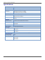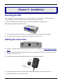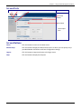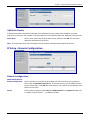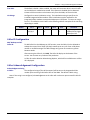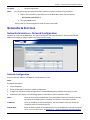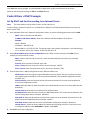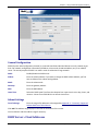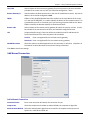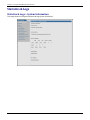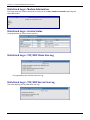
1
MultiModem® rCell Intelligent Wireless Router User Guide MultiModem® rCell User Guide Intelligent Wireless Router MTCBA-Xx-EN3 S000508D, Revision D Copyright This publication may not be reproduced, in whole or in part, without prior expressed written permission from Multi-Tech Systems, Inc. All rights reserved. Copyright © 2013 by Multi-Tech Systems, Inc. Multi-Tech Systems, Inc. makes no representation or warranties with respect to the contents hereof and specifically disclaims any implied warranties of merchantability or fitness for any particular purpose. Furthermore, Multi-Tech Systems, Inc. reserves the right to revise this publication and to make changes from time to time in the content hereof without obligation of Multi-Tech Systems, Inc., to notify any person or organization of such revisions or changes. Check Multi-Tech’s Web site or product CD for current versions of our product documentation. Revision History Revision Date Description A 09/14/11 Initial Release B C 12/17/12 05/01/13 RoHS update. Updated specifications D 12/19/13 Added UL translation Trademarks Trademarks and registered trademarks of Multi-Tech Systems, Inc. include MultiModem, the Multi-Tech logo, and Multi-Tech. Windows is a registered trademark of Microsoft Corporation in the United States and other countries. All other products or technologies referenced in this manual are the trademarks or registered trademarks of their respective holders. Contacting Multi-Tech Knowledge Base The Knowledge Base provides immediate access to support information and resolutions for all Multi-Tech products. Visit http://www.multitech.com/kb.go. Installation Resources To download manuals, firmware, and software, visit http://www.multitech.com/setup/product.go. Support Portal To create an account and submit a support case directly to our technical support team, visit: https://support.multitech.com Technical Support Business Hours: M-F, 9am to 5pm CT Country By Email By Phone Europe, Middle East, Africa [email protected] +(44) 118 959 7774 U.S., Canada, all others [email protected] (800) 972-2439 or (763) 717-5863 World Headquarters Multi-Tech Systems, Inc. 2205 Woodale Drive Mounds View, Minnesota 55112 Phone: 763-785-3500 or 800-328-9717 Fax: 763-785-9874 Warranty To read the warranty statement for your product, please visit: http://www.multitech.com/warranty.go Multi-Tech Systems, Inc. MultiModem rCell User Guide 2 Contents Chapter 1 – Introduction and Description.......................................................................................................... 6 Introduction ........................................................................................................................................................... 6 Package Contents ................................................................................................................................................... 6 Related Documentation ......................................................................................................................................... 6 Safety Warnings ..................................................................................................................................................... 7 Ethernet Ports .................................................................................................................................................. 7 RF Safety .......................................................................................................................................................... 7 Lithium Battery ................................................................................................................................................ 8 Interference with Pacemakers and Other Medical Devices ............................................................................ 8 Front Panel ............................................................................................................................................................. 9 Specifications ....................................................................................................................................................... 10 Power Draw .......................................................................................................................................................... 12 RF Specifications................................................................................................................................................... 12 Antenna System for Cellular Devices ................................................................................................................... 12 PTCRB Requirements for the Antenna .......................................................................................................... 12 FCC Requirements for the Antenna ............................................................................................................... 12 GSM Antenna Requirements/Specifications ................................................................................................. 13 Chapter 2 - Installation ................................................................................................................................... 15 Inserting the SIM .................................................................................................................................................. 15 Making the Connection ........................................................................................................................................ 15 Mounting the Router............................................................................................................................................ 16 Setting the TCP/IP Address................................................................................................................................... 16 Logging into Web Management Software ........................................................................................................... 18 Configuring the Router ......................................................................................................................................... 18 Wizard Setup.................................................................................................................................................. 19 Verifying Signal Strength ...................................................................................................................................... 20 Account Activation for Wireless Devices.............................................................................................................. 21 Resetting the Router ............................................................................................................................................ 21 Chapter 3 - Web Management Software ......................................................................................................... 22 Navigating the Web Management Software........................................................................................................ 22 Submit and Save & Restart ............................................................................................................................ 22 Screen Parts ................................................................................................................................................... 23 3 Multi-Tech Systems, Inc. MultiModem rCell User Guide Contents Screen Buttons............................................................................................................................................... 23 Submenus ...................................................................................................................................................... 24 Web Management Software Screens................................................................................................................... 24 IP Setup ................................................................................................................................................................ 25 Telnet Configuration ............................................................................................................................................ 27 IP Setup > HTTP Configuration....................................................................................................................... 27 IP Setup > DDNS Configuration ...................................................................................................................... 28 IP Setup > SNTP Configuration ....................................................................................................................... 29 IP Setup > Static Routes ................................................................................................................................. 30 IP Setup > Remote Configuration .................................................................................................................. 31 PPP........................................................................................................................................................................ 32 PPP > PPP Configuration ................................................................................................................................ 32 PPP > Wakeup-on-Call ................................................................................................................................... 34 PPP > Wakeup-On-Call Examples................................................................................................................... 36 PPP > Power-On Configuration ...................................................................................................................... 38 PPP > Modem Commands ............................................................................................................................. 38 Networks & Services ............................................................................................................................................ 39 Networks & Services > Network Configuration ............................................................................................. 39 Networks & Services > Service Configuration................................................................................................ 40 Packet Filters > Packet Filters ............................................................................................................................... 41 Packet Filter ................................................................................................................................................... 41 Packet Filters > DNAT Configuration ............................................................................................................. 42 Packet Filters > DNAT Example ...................................................................................................................... 43 Packet Filters > Advanced .............................................................................................................................. 44 GRE Tunnels.......................................................................................................................................................... 45 GRE Tunnels > GRE Tunnels ........................................................................................................................... 45 GRE Tunnels > GRE Routes Configuration ..................................................................................................... 46 DHCP Server ......................................................................................................................................................... 46 DHCP Server > Subnet Settings ...................................................................................................................... 46 DHCP Server > Fixed Addresses ..................................................................................................................... 47 IPSec ..................................................................................................................................................................... 49 IPSec > IPSec .................................................................................................................................................. 49 Tools ..................................................................................................................................................................... 54 Tools > Tools .................................................................................................................................................. 54 Tools > Firmware Upgrade............................................................................................................................. 54 Multi-Tech Systems, Inc. MultiModem rCell User Guide 4 Contents Tools > Load Configuration ............................................................................................................................ 55 Tools > Save Configuration ............................................................................................................................ 55 Statistics & Logs.................................................................................................................................................... 56 Statistics & Logs > System Information ......................................................................................................... 56 Statistics & Logs > Ethernet ........................................................................................................................... 57 Statistics & Logs > PPP ................................................................................................................................... 58 Statistics & Logs > PPP Trace ......................................................................................................................... 59 Statistics & Logs > DHCP Statistics ................................................................................................................. 59 Statistics & Logs > GRE Statistics ................................................................................................................... 59 Statistics & Logs > Modem Information ........................................................................................................ 60 Statistics & Logs > Service Status ................................................................................................................... 60 Statistics & Logs > TCP/UDP Client Live Log .................................................................................................. 60 Statistics & Logs > TCP/UDP Server Live Log ................................................................................................. 60 Statistics & Logs > IPSec Live Log ................................................................................................................... 61 Statistics & Logs > IPSec Log Traces ............................................................................................................... 61 Appendix A – Commonly Supported Subnets Reference Table ......................................................................... 62 Appendix B – Regulatory Information ............................................................................................................. 65 EMC, Safety, and R&TTE Directive Compliance ................................................................................................... 65 47 CFR Part 15 Regulation Class B Devices........................................................................................................... 65 EMC Requirements for Industry Canada .............................................................................................................. 66 Waste Electrical and Electronic Equipment Statement ....................................................................................... 66 WEEE Directive .............................................................................................................................................. 66 Instructions for Disposal of WEEE by Users in the European Union ............................................................. 66 REACH Statement ................................................................................................................................................. 67 Registration of Substances ............................................................................................................................ 67 Substances of Very High Concern (SVHC) ...................................................................................................... 67 Restriction of the Use of Hazardous Substances (RoHS)...................................................................................... 67 Information on HS/TS Substances According to Chinese Standards.................................................................... 68 Information on HS/TS Substances According to Chinese Standards (in Chinese)................................................ 69 依照中国标准的有毒有害物质信息 ........................................................................................................... 69 5 Multi-Tech Systems, Inc. MultiModem rCell User Guide Chapter 1 – Introduction and Description Introduction This guide describes the MultiModem® rCell intelligent wireless routers with an Ethernet II interface. The MultiModem rCell Router is configured for one of three connectivity modes: always-on, wake-up on ring, or dialon demand. The always-on network connection automatically establishes a wireless data connection and allows for around the clock surveillance, monitoring or real time data acquisition of any remote Ethernet device such as a Web camera. If the data link is dropped in the event of poor reception or a complete loss of service, it automatically re-establishes the data link. The wake-up on ring configuration allows the router to “wake up” and initiate a connection when it detects an incoming ring. For security reasons, you can setup the router to wake up based on a particular caller ID number. This configuration is ideal for reducing the costs associated with the modem being online and available 24/7. When configured for dial-on demand, the router only accesses the Internet when data is present. This configuration is ideal for sharing Internet access among networked PCs. Model MTCBA-H3-EN3-P1 Description Quad-band HSPA 7.2 Package Contents Unbundled package without accessories Bundled package with accessories 1 router 1 Quick Start Guide Note: Note: 1 router 1 antenna 1 Ethernet cable You must supply mounting screws, 1 power supply AC or DC power supply, and an 1 Quick Start Guide antenna. Note: You must supply mounting screws. If required, your wireless provider supplies the SIM card. Related Documentation AT Commands: The MultiModem MTCBA-H3-EN3 wireless router is configured using the HSPA-H3 AT Commands. These commands are documented in the Reference Guide number S000505x. Multi-Tech Systems, Inc. MultiModem rCell User Guide 6 Chapter 1 – Introduction and Description Safety Warnings Ethernet Ports CAUTION: The Ethernet ports and command ports are not designed to be connected to a public telecommunication network. ATTENTION: Ports Ethernet et des ports de commande ne sont pas conçus pour être connecté à un réseau de télécommunication public. RF Safety Due to the possibility of radio frequency (RF) interference, it is important that you follow any special regulations regarding the use of radio equipment. Follow the safety advice given below. CAUTION: Maintain a separation distance of at least 20 cm (8 inches) between the transmitter’s antenna and the body of the user or nearby persons. The modem is not designed for or intended to be used in portable applications within 20 cm of the user’s body. Check your local standards regarding safe distances, etc. ● Operating your device close to other electronic equipment may cause interference if the equipment is inadequately protected. Observe any warning signs and manufacturers’ recommendations. ● Different industries and businesses restrict the use of cellular devices. Respect restrictions on the use of radio equipment in fuel depots, chemical plants, or where blasting operations are in process. Follow restrictions for any environment where you operate the device. ● Do not place the antenna outdoors. ● Switch OFF your wireless device when in an aircraft. Using portable electronic devices in an aircraft may endanger aircraft operation, disrupt the cellular network, and is illegal. Failing to observe this restriction may lead to suspension or denial of cellular services to the offender, legal action, or both. ● Switch OFF your wireless device when around gasoline or diesel-fuel pumps and before filling your vehicle with fuel. ● Switch OFF your wireless device in hospitals and any other place where medical equipment may be in use. Sécurité RF En raison de la possibilité d'interférences de radiofréquence (RF), il est important que vous suiviez une quelconque réglementation concernant l'utilisation du matériel radio. Suivez les conseils de sécurité ci-dessous. ATTENTION: Maintenir une distance d'au moins 20 cm (8 po) entre l'antenne du récepteur et le corps de l'utilisateur ou à proximité de personnes. Le modem n'est pas conçu pour, ou destinés à être utilisés dans les applications portables, moins de 20 cm du corps de l'utilisateur. Vérifiez vos normes locales touchant les distances de sécurité, etc.. ● Fonctionnement de votre appareil à proximité d'autres appareils électroniques peuvent causer des interférences si l'équipement est insuffisamment protégé. Respectez les panneaux d'avertissement et les recommandations du fabricant. ● Différentes industries et les entreprises limitent l'utilisation des appareils cellulaires. Respectez les règlements sur l'utilisation des équipements radio dans les dépôts de carburant, les usines chimiques, ou lorsque des opérations de dynamitage sont en cours. Suivez restrictions pour n'importe quel environnement où vous utilisez l'appareil. ● Ne pas placer l'antenne à l'extérieur. 7 Multi-Tech Systems, Inc. MultiModem rCell User Guide Chapter 1 – Introduction and Description ● Éteignez votre appareil sans fil dans un avion. Utilisant des dispositifs électroniques portables dans un avion peut mettre en danger le fonctionnement de l'avion, peut perturber le réseau cellulaire, et est illégal. Le nonrespect de cette restriction peut entraîner la suspension ou le refus des services cellulaires au contrevenant, une action en justice, ou les deux. ● Éteignez votre appareil sans fil lorsque autour de l'essence ou pompes diesel-carburant et avant de remplir votre véhicule avec du carburant. ● Éteignez votre appareil sans fil dans les hôpitaux et tout autre endroit où l'équipement médical peut être utilisé. Lithium Battery ● A lithium battery located within the product provides backup power for the timekeeping. This battery has an estimated life expectancy of ten years. ● When this battery starts to weaken, the date and time may be incorrect. If the battery fails, the board must be sent back to Multi-Tech Systems for battery replacement. ● Lithium cells and batteries are subject to the Provisions for International Transportation. Multi-Tech Systems, Inc. confirms that the Lithium batteries used in the Multi-Tech product(s) referenced in this manual comply with Special Provision 188 of the UN Model Regulations, Special Provision A45 of the ICAO-TI/IATA-DGR (Air), Special Provision 310 of the IMDG Code, and Special Provision 188 of the ADR and RID (Road and Rail Europe). CAUTION: Risk of explosion if this battery is replaced by an incorrect type. Dispose of batteries according to instructions. ATTENTION: Risque d'explosion si cette batterie est remplacée par un type incorrect. Jetez les batteries conformément aux instructions. Interference with Pacemakers and Other Medical Devices Potential interference Radiofrequency energy (RF) from cellular devices can interact with some electronic devices. This is electromagnetic interference (EMI). The FDA helped develop a detailed test method to measure EMI of implanted cardiac pacemakers and defibrillators from cellular devices. This test method is part of the Association for the Advancement of Medical Instrumentation (AAMI) standard. This standard allows manufacturers to ensure that cardiac pacemakers and defibrillators are safe from cellular device EMI. The FDA continues to monitor cellular devices for interactions with other medical devices. If harmful interference occurs, the FDA will assess the interference and work to resolve the problem. Precautions for pacemaker wearers If EMI occurs, it could affect a pacemaker in one of three ways: ● Stop the pacemaker from delivering the stimulating pulses that regulate the heart's rhythm. ● Cause the pacemaker to deliver the pulses irregularly. ● Cause the pacemaker to ignore the heart's own rhythm and deliver pulses at a fixed rate. Based on current research, cellular devices do not pose a significant health problem for most pacemaker wearers. However, people with pacemakers may want to take simple precautions to be sure that their device doesn't cause a problem. Multi-Tech Systems, Inc. MultiModem rCell User Guide 8 Chapter 1 – Introduction and Description ● Keep the device on the opposite the side of the body from the pacemaker to add extra distance between the pacemaker and the device. ● Avoid placing a turned-on device next to the pacemaker (for example, don’t carry the device in a shirt or jacket pocket directly over the pacemaker). Front Panel The front panel contains nine LEDs and the SIM card holder. For details on inserting a SIM card, refer to Insert the SIM Card into Holder. LED Indicator Power Status LNK SPD CD LS Signal 9 Description Lit when there is power. Solid light when the rCell boots up, saves the configuration, restarts, or updates the firmware. Blinks when the router is ready. Link. Blinks when there is transmit and receive activity on the Ethernet link. Shows a steady light when there is a valid Ethernet connection. Speed. Lit when the Ethernet link is at 100 Mbps. If it is not lit, the Ethernet link is at 10 Mbps. Carrier Detect. Lit when data connection has been established. Link Status. Permanently On: Powered on and connected, but not transmitting or receiving. Slow flashing state (5 Seconds) Powered on searching for a connection. Fast flashing state (0.3 seconds) Transmitting and receiving. ALL OFF: Unit is off, not registered on network, or extremely weak signal (0 < = RSSI < 6). 1 Bar ON: Very weak signal (7 < = RSSI <14) 1 Bar and 2 Bar: Weak signal (15 < = RSSI <23) 1 Bar, 2 Bar, and 3 Bar ON: Good signal (24 <= RSSI > = 31) Multi-Tech Systems, Inc. MultiModem rCell User Guide Chapter 1 – Introduction and Description Specifications General Standards Frequency Bands Speed Packet Data* Circuit Swithed Data Physical Description Dimensions Weight (Device Only) Connectors Antenna Connector SIM Holder LAN Connector HSPA Quad-band: 850/900/1900/2100 MHz HSDPA data service of up to 7.2 Mbps HSUPA data service of up to 5.76 Mbps Up to 14.4K bps, non-transparent 3.34 in x 6.05 in x 1.51 in 8.48 cm x 16.51 cm x 3.84 cm 0.72 lbs 0.326 Kg RF Antenna: 50 ohm SMA (female connector) Standard 1.8 and 3V SIM receptacle RJ-45 10/100 BaseT DE9 2.5 mm miniature (screw-on) RS232 Connector Power Connector Environment Operating Temperature1 -40°to 167° F -40° to 75° C Storage Temperature -40° to 185° F -40° to 85° C Humidity Relative humidity 20% to 90% noncondensing Power Requirements Operating Voltage 5 VDC SMS SMS Text and PDU Point-to-Point Cell broadcast Multi-Tech Systems, Inc. MultiModem rCell User Guide 10 Chapter 1 – Introduction and Description Certifications and Compliance EMC Compliance FCC Part 15 Class B EN55022 Class B EN55024 Radio Compliance FCC Part 22, 24 RSS102,132, 133 EN301 489-1 EN489-3 (GPS models only) EN301 489-7 EN301 489-24 EN301 511 Safety Certifications UL/cUL 60950-1 2nd Ed IEC60950-1 2nd Ed am.1 Network Certifications PTCRB AT&T 1UL Listed at 40° C, limited by power supply. UL Certification does not apply or extend to an ambient above 40° C and has not been evaluated by UL for ambient greater than 40° C. “UL has evaluated this device for use in ordinary locations only. Installation in a vehicle or other outdoor locations has not been evaluated by UL. UL Certification does not apply or extend to use in vehicles or outdoor applications or in ambient above 40° C.” Répertorié UL à 40° C, limitée par la puissance d'alimentation. Certification UL ne s'appliquent ni s'étendre à l'une température ambiante supérieure à 40° C et n'a pas été évalué par UL pour ambiante supérieure à 40° C. «UL a évalué cet appareil pour une utilisation dans des endroits ordinaires seulement. Installation dans un véhicule ou d'autres emplacements en plein air n'a pas été évaluée par UL. La certification UL ne s'applique pas ou s'étendre à utiliser dans des véhicules ou les applications en extérieur ou dans ambiante dépasse 40 ° C.» Note: 11 Radio performance may be affected by temperature extremes. This is normal. The radio is designed to automatically fallback in class and reduces transmitter power to avoid damage to the radio. When this occurs depends on the interaction of several factors, such as ambient temperature, operating mode, and transmit power. Multi-Tech Systems, Inc. MultiModem rCell User Guide Chapter 1 – Introduction and Description Power Draw Multi-Tech Systems, Inc. recommends that you incorporate a 10% buffer into your power source when determining product load. Input Voltage= 5.0Volts Idle Mode Typical Maximum Peak Tx Peak Rst (Inrush Current) GSM850 Current(AMPS) Watts HSDPA 0.345 1.76 0.450 2.29 1.20 5.94 3.60 Current(AMPS) 0.345 0.760 1.01 1.40 Watts 1.76 3.84 5.03 Inrush Current (AMPS) (approx. 3ms duration) 2.66 RF Specifications GSM 850 Frequency RX Frequency TX RF Power Stand at 12.5% duty cycle 869 to 894 MHz 824 to 849 MHz 2W EGSM 900 925 to 960 MHz 880 to 915 MHz 2W GSM 1800 GSM 1900 1805 to 1800 MHz 1710 to 1785 MHz 1W 1930 to 1990 MHz 1850 to 1910 MHz 1W Antenna System for Cellular Devices The cellular/wireless performance is completely dependent on the implementation and antenna design. The integration of the antenna system into the product is a critical part of the design process; therefore, it is essential to consider it early so the performance is not compromised. If changes are made to the certified antenna system of the MultiModem, then recertification will be required by specific network carriers such as Sprint. The Antenna System is defined as the UFL connection point from the MultiModem to the specified cable specifications and specified antenna specifications. PTCRB Requirements for the Antenna There cannot be any alteration to the authorized antenna system. The antenna system must maintain the same specifications. The antenna must be the same type, with similar in-band and out-of-band radiation patterns. FCC Requirements for the Antenna The antenna gain, including cable loss, for the radio you are incorporating into your product design must not exceed the requirements at 850 MHz and 1900 MHz as specified by the FCC grant for mobile operations and fixed mounted operations as defined in 2.1091 and 1.1307 of the FCC rules for satisfying RF exposure compliance. The antenna used for transmitting must be installed to provide a separation distance of at least 20cm from all persons and must not transmit simultaneously with any other antenna transmitters. User and installers must be provided with antenna installation instructions and transmitter operating conditions to satisfying RF exposure compliance. Multi-Tech Systems, Inc. MultiModem rCell User Guide 12 Chapter 1 – Introduction and Description GSM Antenna Requirements/Specifications Frequency Range Impedance VSWR Typical Radiated Gain Radiation Polarization TRP/TIS 13 824 – 960 MHz / 1710 – 1990 MHz 50 Ohms VSWR shall not exceed 2.0:1 at any point across the bands of operation 3 dBi on azimuth plane Omni-directional Vertical Including cable loss the total radiated power (TRP) at the antenna shall be no less than +22/24.5 dBm for 850/1900 MHz respectively, and the total isotropic sensitivity (TIS) at the antenna shall be no less than -99/101.5 dBm for 850/1900 MHz respectively. Multi-Tech Systems, Inc. MultiModem rCell User Guide Chapter 2 - Installation Inserting the SIM The router requires the power supply connection to begin operation. It also requires a SIM card (Subscriber Identity Module) to operate on a GSM network. To install the SIM, do the following: 1. Open the SIM door by pressing down on the tab on the top of the door and prying it open. Note: When changing a SIM, disconnect power. 2. Insert the SIM card into the card holder. The image above shows the correct SIM card orientation. 3. Verify that the SIM card fits into the holder properly and then close the cover. Making the Connection 1. Connect an suitable antenna to the SMA connector. For antenna information, see Antenna System for Cellular Devices. 2. Connect an Ethernet cable to the ETHERNET connector on the back of the router and to your computer either directly or via a switch or hub. 3. Attach the appropriate interchangeable blade piece to the power supply module. 4. Screw-on the power lead from the power supply module into the power connection on the router. 5. Plug the power supply into your power source. 15 Multi-Tech Systems, Inc. MultiModem rCell User Guide Chapter 2 – Installation Mounting the Router Before you mount your router to a permanent surface, verify signal strength, refer to Verify Signal Strength in this Chapter. The router can be panel mounted with screws spaced according to the measurement shown. Note: Use either #6 or #8 pan head screws for all four mounts. Setting the TCP/IP Address Establish a TCP/IP connection at the pc so the PC can communicate with the router. Note that these steps are based on Windows XP. 1. Click Start > Control Panel. Double-click Network Connections. The Network Connections screen displays. 2. Right-click Local Area Connection and select Properties. Multi-Tech Systems, Inc. MultiModem rCell User Guide 16 Chapter 2 – Installation The Local Area Connection Properties dialog box displays. 3. Select Internet Protocol [TCP/IP] and click Properties. The Internet Protocol (TCP/IP) Properties screen displays. Note: If the Internet Protocol (TCP/IP) Properties shows your current IP configuration, record this information. You may want to restore the computer’s settings after configuring the router. 4. Enter TCP/IP Properties for a Fixed IP Address. Repeat these steps for each computer on your network a. Select Use the following IP address. b. Enter the computer’s IP Address. Example: 192.168.2.x. Note: The x in the address stands for numbers 101 and up. 17 c. Enter the Subnet Mask. Example: 255.255.255.0 d. Enter the Default Gateway. Example: 192.168.2.1 Multi-Tech Systems, Inc. MultiModem rCell User Guide Chapter 2 – Installation Note: The computer’s settings must be in the same subnet range as the router. The factory default settings for the router are: IP Address: 192.168.2.1 Subnet Mask: 255.255.255.0 e. Select Use the following DNS server addresses. f. Enter the IP Address for the Preferred DNS Server and click OK. Example: 205.171.3.65 g. Close the Local Area Properties screen by clicking OK. Logging into Web Management Software The router’s Web Management software allows you to configure the Ethernet interface. To login: 1. Verify that the Status LED is blinking to indicate that router is ready. 2. Open a web browser. 3. Enter the default Gateway Address, http://192.168.2.1. The Login window displays. 4. Enter the default User Name and Password and click Login. The default for both is admin. The Web Management displays. Note: User name and password are case-sensitive. Change the default password to improve router security. See Authentication for more information. Configuring the Router Use Wizard Setup for basic router configuration. To setup additional features and functions, refer to Chapter 3, Web Management Software. In the Web Management Software: 1. Click Wizard Setup. Multi-Tech Systems, Inc. MultiModem rCell User Guide 18 Chapter 2 – Installation The Wizard Setup screen displays. Wizard Setup A minimum router configuration is provided using the Wizard Setup. This provides a quick way to enter and save information needed to create a connection to the Internet. The table below provides the information for the minimum configuration. IP Configuration IP Address The default is 192.168.2.1. To change it, simply enter your own IP address. Mask The default is 255.255.255.0 DNS Enter the primary DNS IP address for the system. The default is 0.0.0.0 PPP Configuration PPP The default is disable. To connect to the Internet, you need to enable PPP. Depending on the model, commands may need to be issued to the integrated cellular modem before connecting to the wireless service. To issue commands to the integrated cellular modem, PPP must be disabled and telnet port 5000 used. Dial-on- The default is disable. Demand 19 Idle Time Out Sets the amount of time the PPP link stays active before disconnecting. Setting the value to zero causes the link to stay active continuously. Dial Number Enter the dial number. This number connects you to the Internet. APN For HSPA, the number is *99***1#. For HSPA models, enter the APN (Access Point Name). The APN is assigned by your wireless service provider. Init String You can set up to 4 router initialization strings. Multi-Tech Systems, Inc. MultiModem rCell User Guide Chapter 2 – Installation PPP Authentication Authenticatio Click the button corresponding to the authentication protocol you want to use n to negotiate with the remote peer. PAP, CHAP, or PAP-CHAP. T Default = PAP-CHAP y p e Username Enter the PPP Username. This name authenticates the remote peer. Password Enter the PPP Password. This password authenticates the remote peer. 1. Enter settings. 2. Click Submit. 3. Click Save & Restart to reboot. Notes: To save changes, click Submit on the bottom of most screens. After saving changes, you need to restart the device for the changes to take effect. To restart, click Save & Restart on the Menu bar. You can wait to restart until you finish changing settings on multiple pages. Chapter 3 describes additional features and functions. Access Point Names Your wireless service provider assigns an APN (Access Point Name), but you may have to ask for it. An access point is an IP network to which a MultiModem rCell Router connects. The Web Management software asks for the APN on the Wizard Setup screen and the PPP screen. Provider Fees Your provider charges you for data usage. Check with your provider for rates and limitations. If you plan to use the router for large amounts of data transfers, Multi-Tech recommends an unlimited data plan with your account. Multi-Tech is not responsible for any charges relating to your cellular bill. Verifying Signal Strength To communicate directly with the cellular modem to verify signal strength, telnet to the modem. Note: Ensure that the Status LED is blinking, indicating that the router is ready. Ensure that PPP is disabled before verifying signal strength. 1. To Telnet to the modem. You can access the modem thru the Run icon or from the Command Prompt: Click Start I Run icon. In the Open window, enter cmd and then press ENTER. or Click Start I All Programs I Accessories I Command Prompt Multi-Tech Systems, Inc. MultiModem rCell User Guide 20 Chapter 2 – Installation In the command window, type telnet 192.168.2.1 5000 At the Login prompt, type the default user name: admin (all lower-case). Press ENTER At the Password prompt, type the default password: admin (all lower-case). Press ENTER 2. In the command window, type AT+CSQ . The router responds with the received signal strength (rssi). Signal Strength – RSSI 10 – 31 Sufficient 0–9 Weak or Insufficient 99 Insufficient Once you have a good signal for where you are going to place the router, either refer back to Optional Mounting in this Chapter if you are permanently mounting your router or continue with Account Activation for Wireless Devices. Account Activation for Wireless Devices Please refer to Multi-Tech’s Cellular Activation Web site at http://www.multitech.com/activation.go for information on activating your cellular modem. Note: If you need remote access to your MultiModem over the Internet for remote configuration, you need to ensure that your wireless network provider has provisioned mobile terminated data and fixed or dynamic public IP address in which they can configure the network to redirect any incoming connection to that predefined IP. Resetting the Router To reset the router: ● Hold the Reset button in until the Status Light goes out. Then, release it. This also sets the username and password back to admin and admin and the IP address to the default, 192.168.2.1. 21 Multi-Tech Systems, Inc. MultiModem rCell User Guide Chapter 3 - Web Management Software Use the Web Management software to configures your router’s Ethernet functions. Navigating the Web Management Software This section explains the menu structure and the navigation buttons of the router’s Web Management software. Menu Bar IP Setup: Sets up a General Configuration, HTTP, DDNS, SNTP, Static Routes, and Remote Configuration. PPP: Sets up the PPP authentication, dial-on-demand, router authentication, and Wakeup on Call. Networks & Services: Defines networks and services to make them available to other functions such as allowed packet filters, static routes, remote configuration, DNAT, and GRE tunnels and routes. Packet Filters: Defines filter rules, DNAT configuration, and ICMP rules. GRE Tunnels: Generic Routing Encapsulation (GRE). Defines the remote network and the tunnel through which traffic is to be routed. DHCP Server: Configures the DHCP server settings. IPSec: Allows device to support LAN-to-LAN VPN tunneling with 3DES and AES 128-192-256 encryption support Tools: Sets DDNS Force Update, displays DDNS Status, resets the modem, and provides screens for Firmware Upgrade, Load Configuration, and Save Configuration. Statistics & Logs: Shows statistics and logs maintained by the router. Save & Restart: Saves your settings and reboots. Help Index: Accesses the online Help text. Submit and Save & Restart To save changes, click Submit on the bottom of most screens. After saving changes, you need to restart for the changes to take effect. To restart, click Save & Restart on the Menu bar. You can wait to restart until you finish changing settings on multiple pages. Multi-Tech Systems, Inc. MultiModem rCell User Guide 22 Chapter 3 – Using the Web Management Software Screen Parts Menu Bar Submenu Title Submenu List Screen Buttons Screen Name Screen Input Area Screen Buttons Home: Click this button to return to the Home screen. Wizard Setup: Click this button to display the Wizard Setup screen on which you can quickly set up your MultiModem rCell Router with basic configuration settings. Logout: Click this button to Logout and return to the login screen. Help: Click this button to display the Help text. 23 Multi-Tech Systems, Inc. MultiModem rCell User Guide Chapter 3 – Using the Web Management Software Submenus The submenus display on the left side of the screen. The following table shows the sub-menu selections under each main menu category. IP Setup PPP General Configuration HTTP Configuration DDNS Configuration SNTP Configuration Static Routes Remote Configuration PPP Configuration Wakeup on Call Power On Config Modem Commands DHCP Server Subnet Settings Fixed Addresses IPSec IP Sec Networks & Services Network Configuration Service Configuration Packet Filters Packet Filters DNAT Configuration Advanced Tools Tools Firmware Upgrade Load Configuration Save Configuration GRE Tunnels GRE Tunnels GRE Routes Statistics & Logs SysInfo Ethernet PPP PPP Trace DHCP Statistics GRE Statistics Modem Info Service Status TCP/UDP Client Live Log TCP/UDP Server Live Log IPSec Live Log IPSec Log Traces Web Management Software Screens The rest of this chapter describes each of the Web Management software screens. Multi-Tech Systems, Inc. MultiModem rCell User Guide 24 Chapter 3 – Using the Web Management Software IP Setup Setup > General Configuration In the General Configuration, you will set the general system-based parameters. 25 Multi-Tech Systems, Inc. MultiModem rCell User Guide Chapter 3 – Using the Web Management Software General Configuration Date and Time: The system date and time display in these formats: MM/DD/YYYY / HH:MM:SS. A real time clock is part of SNTP to display proper time. IP Configuration Enter the following addresses for the Ethernet interface. IP Address: Default = 192.168.2.1 Mask: Default 255.255.255.0 Default Gateway: Default 0.0.0.0 Primary DNS: Default 0.0.0.0 Secondary DNS: Default 0.0.0.0 For more information, see Appendix A – Commonly Supported Subnets Reference Table. Auto Dial out Configuration Auto Dialout: Check the box to enable/disable Auto Dialout. Default = Enable. The Auto Dialout settings allow you to use the integrated cellular modem directly with no router functionality. This is accomplished using redirector software on your pc. This software creates a virtual serial port allowing your pc to communicate with the integrated cellular modem over IP using telnet. Raw Dialout: Check the box to enable/disable raw mode for an Auto Dialout session. Default = Disable. Auto Dialout Login: Check the box to enable or disable Auto Dialout Login feature. Default = Enable. The Auto Dialout port is the telnet port used by the redirector software on your pc to communicate to the integrated cellular modem. Auto Dialout Port: Enter the serial Auto Dialout Port number. Default = 5000. Handle EIA Signal: Check the box to enable/disable the EIA standard signal characteristics (time and duration) used between different electronic devices. Inactivity: Enter the time in seconds that the auto dialout session will stay active before going inactive. Syslog Configuration Syslog: Check the box to enable or disable Syslog. Default = Disable. Syslog Server IP Address: If a Remote Syslog Server IP Address is specified, the syslog feature acts as a remote Syslog. Auto Discovery Auto Discovery: heck the box to enable or disable Auto Discovery to broadcast (MAC level), the MAC Address, IP Address, and DHCP information to the configured server port. Default = Enable. The router will send a broadcast packet on the specified server port every 10 seconds or whatever interval the broadcast timer is set to. Multi-Tech Systems, Inc. MultiModem rCell User Guide 26 Chapter 3 – Using the Web Management Software Server Port: Enter the Server Port Number. Default port is 1020. Broadcast Timer: Enter the amount of time in seconds for the auto-discovery packet granularity of periodic broadcasting. Default is 10 seconds. Auto Reboot Timer Configuration Auto Reboot Timer: Enter the number of hours to lapse between each automatic reboot. The default of zero deactivates the timer. Range is 0 to 999. Telnet Configuration Enables/Disables the Telnet port. The default is Enable. This is specifically for telnet port 23 for technical support debug. You can still access the integrated cellular modem using port 5000 when this is disabled. Ensure that PPP is also disabled before telnetting to the port. IP Setup > HTTP Configuration HTTP Configuration HTTP Port: Enter the port number on which the HTTP server will listen for requests. Default is 80. HTTP Time-out: Set the HTTP session in seconds. The default is 120 seconds. Authentication Username: Enter the Username that can access to the Web Management software. Default is admin. This username and password are also used for telnet access to the router and integrated cellular modem. Password: Enter the Password for access to the Web Management software. Default is admin. Notes: User name and password are case-sensitive. Change the password to one that is more secure. Passwords can be up to 100 characters. 27 Multi-Tech Systems, Inc. MultiModem rCell User Guide Chapter 3 – Using the Web Management Software IP Setup > DDNS Configuration DDNS (Dynamic Domain Naming System) is dependent upon cellular network/account configuration. DDNS allows you to have a static domain name with a dynamic IP address. Whenever your dynamic IP address changes, it is submitted to the DDNS server where your domain name is updated to point to the new IP address. Note: You have to register with a DDNS server to use this feature. General DDNS: Check the Enable or Disable box. This enables/disables DDNS. Default = Disable. Use Check IP: Check the Enable or Disable box. If enabled, the program will query the server to determine the IP address before it performs the DDNS update (the IP address is still assigned by the wireless provider and the DDNS will be updated based on the address returned by Check IP Server). If disabled, the program will perform the DDNS update using the IP address that it obtains from the PPP link. Default = Enable. Check IP Server: Enter the Server name from which the currently assigned IP address is obtained. This check IP server is a server the router accesses to check it’s current IP address. Check IP Port: Enter the port number of the Check IP Server. Default is 80. Server: Enter the Server name to which the IP Address change is registered. Example: members.dyndns.org Port: Enter the Server port number. Default is 80. Max Retries: Enter the maximum number of tries that will be allowed if the update fails. Default = 5. Range is 0 – 100. Update Interval: Enter the intervals in days that will be allowed to pass when there is no IP Address change. At the end of this interval, the existing IP Address will be updated in the server so that it will not expire. Default = 28 days. Range is 1 – 99 days. System: Sets the system registration type as either Dynamic or Custom. Default = Dynamic. Multi-Tech Systems, Inc. MultiModem rCell User Guide 28 Chapter 3 – Using the Web Management Software Domain: Enter the registered Domain name. Authentication Username: Enter the Username that can access the DDNS Server. Default = NULL. You should have received your username when you registered with the DDNS service. Password: Enter the Password that can access the DDNS Server. Default = NULL. You should have received your password when you registered with the DDNS service. IP Setup > SNTP Configuration General Configuration SNTP Client: Enable or disable the SNTP Client to contact the configured server on the UDP port 123 and set the local time. The default is Disable. Server: Enter the SNTP server name or IP address to which the SNTP Client must contact in order to update the time. No default. Polling Time: Enter the polling time at which the SNTP client requests the server to update the time. Default is 300 minutes. Time must be entered in minutes. 29 Multi-Tech Systems, Inc. MultiModem rCell User Guide Chapter 3 – Using the Web Management Software Time Zone Configuration Time Zone: Enter your time zone. Default = UTC (Universal Coordinated Time, Universal Time). See the following Web site for Time Zone information: http://wwp.greenwichmeantime.com/info/current-time.htm Time Zone Offset: Enter +/- hh:mm. Default = +00:00. Offset is the amount of time varying from the standard time of a Time Zone. Daylight Configuration Daylight Saving: Enables/disables Daylight Saving mode. The default is Enable. Daylight Saving Offset: Set the offset to use during Daylight Saving mode. Default is +60 minutes. Enter the time in + / - minutes. Daylight Saving Start Time Start Ordinal: Set the start ordinal to use during Daylight Saving mode. Options are first/second/third/fourth/last. Default is second. Daylight Saving time usually starts at the same time on the same day of the week in the same month every year. Each day of the week occurs four or five times a month. Therefore, you will be selecting the week in which daylight saving time starts: the first, second, third, fourth or the last of the month. Start Month: Set the start month to use during Daylight Saving mode. Default is March. Start Day: Set the start weekday to use during Daylight Saving mode. Default is Sunday. Start Time: Set the start time to use during Daylight Saving mode. Default is 02:00 (hh:mm). Daylight Saving End Time End Ordinal: Set the end ordinal to use during Daylight Saving mode. Select the week in which daylight saving time ends. Options are first/second/third/fourth/last. Default is first. End Month: Set the end month to use during Daylight Saving mode. Default is November. End Day: Set the end weekday to use during Daylight Saving mode. Default is Sunday. End Time: Set the end time to use during Daylight Saving mode. Default is 02:00 (hh:mm). IP Setup > Static Routes Routing information is used by every computer connected to a network to identify whether it is sending a data packet directly to the firewall or passing it on to another network. The options to Delete or Edit a route after it has been defined and added are available by using the table at the bottom of the screen. Multi-Tech Systems, Inc. MultiModem rCell User Guide 30 Chapter 3 – Using the Web Management Software Add Static Routes IP packets destined for the network indicated in the drop down box are routed to the IP address in the box pointed to by the arrow. The networks in the drop down box can be defined under the ‘Networks & Services’ tab. Static Route: Select a static route from the drop down list box, and then click Add. The new route displays at the bottom of the screen. Note: The Static Route screen will not display until the network is defined under Networks & Services. IP Setup > Remote Configuration Remote Configuration Add Network/Host for Remote Configuration: Delete: 31 Select a network or host from the drop down box. You can define more networks or hosts under the Network & Services tab. The choices are Any, LAN, and WAN Interface. Choose all that apply. Click Add after each selection. The network or host displays at the bottom of the screen. You will have the option to delete Any and WAN Interface in the Options window once it is added. Click on Delete in the Options window. Multi-Tech Systems, Inc. MultiModem rCell User Guide Chapter 3 – Using the Web Management Software PPP PPP > PPP Configuration NAT Configuration NAT Enable/disable NAT (Network Address Translation). The default is Enable. If NAT is enabled: Your LAN can use one set of IP addresses for internal traffic and a second set of addresses for external traffic. In other words, the router with NAT does the simple IP routing between the LAN interface and the WAN interface. NAT hides the LAN address behind a single IP address on the wireless side. Your internal addresses are shielded from the public Internet. If NAT is disabled: The router functions without performing any address translation on the packets passing through it. Masquerading of packets originating from the LAN is disabled. Address translation of packets arriving from the WAN is also disabled. Any DNAT Configuration previously setup in the DNAT Configuration screen is disabled. This prevents the user from adding any DNAT rules, which if allowed would defeat the purpose of enabling Routing. Multi-Tech Systems, Inc. MultiModem rCell User Guide 32 Chapter 3 – Using the Web Management Software Note: For routing to take effect, save the configuration after enabling it. It won’t be effective on the fly at runtime. PPP General PPP Enable/disable PPP. The default is Disable. When enabled, the unit functions as a router. PPP must be disabled to access the integrated cellular modem directly using telnet port 5000. If PPP is enabled, you cannot access the integrated cellular modem. Dial-on-Demand: Enable/disable Dial-on-Demand. The default is Disable. If you disable it, the router will always stay connected unless the Idle Time Out expires. When Dial-on-Demand is enabled, use the ‘Wakeup on Call’ settings under the PPP menu to configure the settings for re-establishment of the connection. Idle Time Out: Set the amount of idle time that will pass before the router will timeout. The default is 180 seconds. If the time expires, the PPP connection to the Internet will disconnect. Any IP packets from the LAN side or IP traffic from the wireless side will reset this timer and prevent the connection from dropping. Connect Time Out: Set the number of seconds to wait for a connection while in receive mode before timing out. Dialing Max Retries: Enter the number of dialing retries allowed. The default is zero, which means an infinite number is allowed. Range 0 to 100. Authentication Authentication Type: Set the authentication protocol type that will negotiate with the remote peer: pap/chap/pap-chap. Default is pap-chap. Username: Enter the Username with which the remote peer will authenticate. You can leave this field blank, if desired. Username is limited to 60 characters. Password: Enter the Password with which the remote peer will authenticate. You can leave this field blank, if desired. Password is limited to 60 characters. ICMP Keep Alive Check Keep Alive Check: Enable/disable Keep Alive Check. The default is Disable. This is used to periodically check that the Internet connection is up. If it is not, the router will try to reconnect. Keep Alive Type: Select ICMP or TCP (the protocol type for Keep Alive). Host Name: Enter the Host Name or IP Address for Keep Alive Check. No default. TCP Port: Enter the TCP Port number to connect with the TCP server. Interval: Set the number of seconds for Keep Alive Check. Default is 60 seconds. ICMP Count: Set the number of ICMP Keep Alive Checks to be sent to the specified host. Default is 10. Modem Configuration Refer to the Customer Activation Notices included with the product for proper information to enter. Dial Number: Set the dial number to be dialed. Default is NULL. 33 For HSPA models, the Dial Number is *99***1# Multi-Tech Systems, Inc. MultiModem rCell User Guide Chapter 3 – Using the Web Management Software For EVDO models, the Dial Number is #777 Dial Prefix: Set the modem dial prefix. The default is ATDT. Connect String: Set the modem Connect String. The default is CONNECT. APN: Enter the APN (Access Point Name). For more information on APN, refer to Access Point Names. Init String 1-4: Configure the modem init strings. You can set up to 4 modem initialization strings. Baud Rate: Baud Rate only displays on certain models and is set at 230.4K, by default. The default setting is set for maximum performance. PPP > Wakeup-on-Call The Wakeup-on-Call feature allows the router to wake up and initiate a connection when there is an incoming call or LAN activity. If you desired some security with this feature, you can set up the router to wake up based on Caller ID or SMS instead of allowing all incoming calls to wakeup the router. Dial-on-Demand in the IP Setup menu must be enabled for these settings to have any affect. The Wakeup-on-Call feature will reduce the cost incurred when a router is online and available 24/7. Note: When provisioning this feature, you must allow incoming calls, SMS capability, and/or caller-id. Wakeup-on-Call Configuration Wakeup on Call: Enable/disable the Wakeup-on-Call feature. The default is Disable. Wakeup-on-Call occurs when a ring or caller ID is detected. This will trigger the router to reconnect after the ‘Time Delay’ expires. Time Delay: Enter the amount of time that you want to pass between the reception of a call and the initiation of the Wakeup-on-Call connection. A time delay is needed to make sure that the incoming call has ended before the connection is initiated. The default is 10 seconds. Dial-on-Demand Multi-Tech Systems, Inc. MultiModem rCell User Guide 34 Chapter 3 – Using the Web Management Software from LAN: The default is disable. When enabled, the router will reconnect when it sees IP traffic on the LAN that is needed to be routed. If this feature is disabled, Dial-on-Demand initiates a PPP connection to the Internet only from the WAN, not from the LAN. Init Strings: Configure the router initialization string. This initialization string is specific to the installed integrated cellular modem. Some initialization may be required for the integrated cellular modem to accept the Wakeup-on-Call feature. Init-num can range from 1-5. The default is NULL. Refer to the following table for examples of the Init String depending on model. Model Init 1 MTCBA-H3-EN3 AT+CNMI= 1,1,0,1,0 Init 2 Init 3 AT+CLIP= 1 Init 4 Ack Comment AT+CNM A Ring, for any number/call to trigger Wakeup-on-Call. Caller ID Configuration Add “Wakeup on Call” Caller ID: To add Caller ID to the Wakeup-on-Call function, enter the Caller ID to be allowed to wakeup the router. Enter ‘RING’ (all Caps) to wake up on any call. Enter a CID phone number or an SMS message. The SMS message string must not contain any spaces between words. After entering the Caller ID, click Add. The Caller ID displays at the bottom of the screen. You can enter any number of IDs you desire. A Caller ID can be edited or deleted using Options, which will be available once a Caller ID is displayed. Caller Acknowledgement Configuration Acknowledgement String to Caller: The configured string of (0 to 40 characters) will be sent to the integrated cellular modem upon receiving a valid caller ID from the WAN. The default is NULL string. Note: If the string is not configured, acknowledgement to the caller will not be sent upon successful caller ID reception. 35 Multi-Tech Systems, Inc. MultiModem rCell User Guide Chapter 3 – Using the Web Management Software PPP > Wakeup-On-Call Examples Example 1 – Determine if Router Support Incoming Calls and Caller ID 1. On the PPP > PPP Configuration screen, make sure that PPP is Disabled. 2. On the PPP > Wakeup-on-Call screen, make sure that Wakeup-on-Call is Disabled. 3. Open a command prompt by clicking the Start button and selecting Run. 4. Type CMD to open the command window. Click OK. 5. When the command window opens, telnet to the router. Note: 5000 is the router port number. a. Enter your username and password to login. b. Enter an AT command to make sure you receive a response, for example, OK. c. On HSPA models, enter the Command AT+CNUM to determine the dial number of your router. 6. From another phone, call your router using the number identified in Step 5.3. This will let you know if the RING message shows. 7. To enable Caller ID, enter the AT+CLIP=1 command on the command screen and make the call again to see if it shows Caller ID information. Notes: ● Step 5c must show the RING or CALLER ID information in order for the Wakeup-on-Call function to work. ● Some wireless providers might not provide caller ID information if you have only a data plan. Example 2 – Set Up the Ethernet Router to Activate on ALL Incoming Calls 1. On the PPP >PPP Configuration screen, set up the following parameters and click Submit. PPP General ● Make sure that PPP is enabled. ● Make sure Dial-on-Demand is enabled. ● Set the Idle Time Out to the number of seconds you desire. Authentication ● Note: Your wireless service provider may require you to have a separate PPP Use name and Password. If so, enter them here. If a username and password are required, your wireless provider would have given them to you when you activated your account. Modem Configuration ● Make sure your Dial Number is entered correctly, for HSPA models, the Dial Number is *99***1# 2. On the PPP > Wakeup-on-Call screen, set up the following parameters and click Submit. Wakeup-on-Call Configuration ● Select Enable for Wakeup-on-Call. ● Set the Time Delay to 3 seconds. You can use the 10 second default. Multi-Tech Systems, Inc. MultiModem rCell User Guide 36 Chapter 3 – Using the Web Management Software ● All Init Strings should be empty. Caller ID Configuration ● Enter the string RING to the Caller ID list. ● Click Add to save the string to the Caller ID list. 3. Click Save & Restart to save all the settings and reboot. Example 3 – Set Up the Ethernet Router to Activate on Matching Caller IDs Only: 1. On the PPP > PPP Configuration screen, set up the following parameters and click Submit. PPP General ● Make sure that PPP is enabled. ● Make sure Dial-on-Demand is enabled. ● Set the Idle Time Out to the number of seconds you desire. Authentication ● Your wireless service provider may require you to have a separate PPP username and password. If so, enter them here. Note: If a username and password are required, your wireless provider would have given them to you when you activated your account. Modem Configuration ● Make sure your Dial Number is entered correctly, for HSPA models, the Dial Number is *99***1# 2. On the PPP > Wakeup-on-Call screen, set up the following parameters and click Submit. Wakeup-on-Call Configuration ● Select Enable for Wakeup-on-Call. ● Set the Time Delay. You can use the 10 second default. ● Enter the Init Strings, Set Wakeup Init String 1 by entering AT+CLIP=1 for HSPA models only. Caller ID Configuration ● Enter a caller’s ID that you want added to the Caller ID list. ● Click Add to save each Caller ID as it is entered to the Caller ID list. 3. Click Save & Restart to save all the settings and reboot. 37 Multi-Tech Systems, Inc. MultiModem rCell User Guide Chapter 3 – Using the Web Management Software PPP > Power-On Configuration The Power-On Configuration feature allows you to set an initialization string that will be sent to the router upon boot up. Power-On Init String Configuration Power-On Init String: Note: You can enter a string of 0 to 40 characters that will be sent to the router upon boot up. All commands will initialize before you proceed with regular PPP related activity. When no initialization string is configured, regular functionality of the router is retained. PPP > Modem Commands Setting up certain modem commands will allow an external application to query modem information (based on the commands entered). The application can use the URL HTTP://xxx.xxx.xxx.xxx/modeminfor.html to get the IP address that is currently assigned to the integrated cellular modem after the PPP connection is established. It also will show the results of up to ten AT commands entered here. Modem AT Commands Configuration These commands will be sent every time a PPP connection to the network is initiated. HSDPA AT Commands Examples: AT+CGSN Product Serial Number AT+CGMR Software Version AT+CSQ Signal Quality AT+CNUM Wireless Subscriber Number AT+COPS? Network Information (Operator) Multi-Tech Systems, Inc. MultiModem rCell User Guide 38 Chapter 3 – Using the Web Management Software AT+CREG? Notes: Network Registration You can also retrieve the integrated cellular modem information without using a browser: Make a TCP connection to port 80 (same as the Web Admin port) and send data as: GET /atinfor.html HTTP/1.1 Then press Enter twice. Refer to the AT Command Reference Guide for other commands. Networks & Services Networks & Services > Network Configuration Networks or Hosts can be added here. The options to Delete or Edit a network after it has been defined and added are available by using the table at the bottom of the screen. Network Configuration Enter the Name, IP Address, and Mask for a new Network or Host. Notes: A Network/Host Name: ● Cannot be edited. ● Cannot be deleted if it is used in another configuration. ● Changes are reflected in all the configurations in the Web Management software where they are used. ● If added here will display in the following sections: Static Routes, DNAT, and Packet Filters. Name: Enter the name of the Network/Host. The same address-mask pair should not already be present in the displayed list. The Name is limited to 15 characters maximum. IP Address: Enter the IP Address of the Network/Host. The same address-mask pair should not already be present in the displayed list. Subnet Mask: Enter the Network Mask of the Network/Host. For Host addresses, the mask is entered as 32. For more information, see Appendix A -- Table of Commonly Supported Subnets. 39 Multi-Tech Systems, Inc. MultiModem rCell User Guide Chapter 3 – Using the Web Management Software When you click Add, the defined network displays at the bottom of the screen. Networks & Services > Service Configuration On this screen you can specify the standard set of well known services available on the system. These services enable the configuration of the user-defined services. The options to Delete or Edit a service after it has been defined and added are available by using the table at the bottom of the screen. Multi-Tech Systems, Inc. MultiModem rCell User Guide 40 Chapter 3 – Using the Web Management Software Service Configuration Enter the Name, Protocol, Source Port/Client, and Destination Port/Server for the new Service and click Add. The new service displays at the bottom of the screen. Notes: A Service Name: ● Cannot be edited. ● If used in another configuration, cannot be deleted. ● Changes are reflected in all the configurations in the Web Management software where they are used. ● If added here will display in the following sections: DNAT, Packet Filters. Name: Enter the name of the Service which is limited to 16 characters. It has to be unique. Protocol: Enter the type of protocol (TCP, UDP). Source Port: Enter the Destination Port for this service. The source and destination ports can be entered either as a single port or a range using a colon as the separator. Destination Port: Enter the name of the Destination Port for the service. Packet Filters > Packet Filters Use the table at the bottom of the page to delete or edit an existing packet filter rule. Packet Filter From (Host/Networks): Enter the network/host from which the packet must originate for the filter rule to match. The Any option, which matches all IP addresses regardless of whether they are officially assigned addresses or private addresses, may also be entered. The network/host must be pre-defined in the Networks section. Service: 41 Enter the service that is to be matched with the filter rule. These services must be predefined in the Services section. These services precisely define the traffic to be filtered. Multi-Tech Systems, Inc. MultiModem rCell User Guide Chapter 3 – Using the Web Management Software To (Host/Networks): Enter the network/host to which the packet must send for the filter rule to match. The Any option, which matches all IP addresses regardless of whether they are officially assigned addresses or private addresses, may also be entered. The network/host must be pre-defined in the Networks section. Action: Enter the action that the packet filter executes if the rule matches any traffic traversing the firewall. Types of actions defined are: Accept: Allows/accepts all packets that match this rule. Reject: Blocks all packets matching this rule. Notifies the host that the packet was rejected. Drop: Blocks all packets matching this rule, but dose not notify the host. This is a silent drop. Log: Logs packets matching the rule; for example, the corresponding source address, destination address, and service. When you click Add, the packet filter rule displays at the bottom of the screen. Packet Filters > DNAT Configuration Destination Network Address Translation (DNAT) is a process that allows the placing of servers within the protected network and making them available for a certain service to the outside world. The DNAT process running on the router translates the destination address of incoming packets to the address of the real network server on the LAN. The packets are then forwarded. You can Delete or Edit a DNAT rule after it has been defined and added by using the table at the bottom of the screen. Note: When adding rules, at least one host must be defined in the Network Configuration section. DNAT Configuration Allow Access: Select a network or host to which IP packets will be allowed and re-routed. The network/host must be pre-defined in the Network Configuration section. External Service: Select the External Service that you want allowed. The service must be defined in the Service Configuration section. LAN IP: Select the LAN IP to which the packets are to be diverted. Only one host can be defined as the destination. Internal Service: Select the Internal Service to be the destination. Internal Source: Select the source address for packets that are going to be sent. If you do not want to change the address, select NOCHANGE. Multi-Tech Systems, Inc. MultiModem rCell User Guide 42 Chapter 3 – Using the Web Management Software Click Save after making changes. The defined DNAT configuration displays at the bottom of the screen. Delete or edit settings by clicking the Edit or the Delete buttons. Packet Filters > DNAT Example Set Up DNAT and Port Forwarding to an Internal Device Note: The internal device can be camera, meter, security device, etc. For this example, assume the device is on a LAN with an IP address of 192.168.2.100 and the port to access the device is port 7700. 1. On the Network & Services > Network Configuration screen, set up the following parameters and click Add. Name: Enter a name for the LAN device. IP Address and Subnet Address: Enter the IP address and subnet address of the device. Example: Name = MeterIP IP Address = 192.168.2.100 Subnet Address = 255.255.255.255. The subnet mask in the network configuration is not defined using x.x.x.x notation. It uses ‘bit’ notation. So 255.255.255.255 = 32. 2. On the Network & Services > Service Configuration screen, define a service name and click Add. For this example, the service will be a meter. Name: Enter a name for the service (use a name that will identify the service for you). Example: MeterPort Protocol: Select a protocol. Example: tcp or udp S-Port / Client: Enter the source port for this service. Example: 1:65535 D-Port / Server: Enter the destination port for this service. Example: 7700 3. On the Packet Filters > DNAT Configuration screen, define the DNAT rule. Allow Access: Select the original target network/host of the IP packets that you now want rerouted. The original target network/host is the one previously defined in the Network Configuration section. Example: Any External Service: Select the External Service that you want allowed. The service must be defined in the Service Configuration section. LAN IP: Select the LAN IP to which the packets are to be diverted. Only one host can be defined as the destination. Internal Service: Select the Internal Service to be the destination. Pre DNAT Service: Select the service for the Pre-DNAT destination. This service was just defined in the Service Configuration section. Example: MeterPort Post DNAT IP: Select the destination to which the IP packets are to be diverted. Only one host can be defined as the Post DNAT destination. Example: MeterIP Post DNAT Service: Select the service for the Post DNAT configuration. Example: MeterPort Internal Source – Select the source address for packets that are going to be sent. If you do not want to change the address, select NOCHANGE. Example: NOCHANGE 4. Click Save to save the configuration. 43 Multi-Tech Systems, Inc. MultiModem rCell User Guide Chapter 3 – Using the Web Management Software 5. Click Save and Restart once you have completed and submitted all the screens on which you have made changes. Packet Filters > Advanced Connection Tracking H323: Enable/disable the forwarding of H323 packets across the firewall. Default is disabled. PPTP: Enable/disable PPTP Packet Pass-through (PPTP NAT support). Default is disabled. CMP Configuration The Internet Control Message Protocol (ICMP) is used to test the network connections and the functionality of the firewall and is also used for diagnostic purposes. ICMP on Firewall and ICMP Forwarding always apply to all IP addresses; i.e., Any. When these are enabled, all IP hosts can Ping the firewall (ICMP on Firewall) or the network behind it (ICMP Forwarding). ICMP on LAN: Enable/disable the transfer of ICMP packets on the LAN interface. Default is enabled. ICMP on WAN: Enable/disable the transfer of ICMP packets on the WAN interface. Default is enabled. ICMP Forward: Enable/disable the forwarding of ICMP packets through the firewall into the local network. Default is enabled. Multi-Tech Systems, Inc. MultiModem rCell User Guide 44 Chapter 3 – Using the Web Management Software GRE Tunnels GRE tunneling and GRE routing together are referred to Generic Routing Encapsulation (GRE). GRE Routing is an integral part of GRE tunneling. First, the GRE Tunnels are created using the GRE Tunnel Configuration. Then the routes for the remote networks that are to be routed through a tunnel need to be specified in the GRE Routes Configuration. Thus, all the traffic destined to remote networks associated to a tunnel will get routed through that tunnel. GRE Tunnels > GRE Tunnels Tunneling allows the use of a public network to convey data on behalf of two remote private networks. It is also a way to transform data frames to allow them to pass networks with incompatible address spaces or even incompatible protocols. If you want to read more about how this works, see the online Help. GRE Tunnel Configuration Tunnel Name: Enter a name for the new tunnel. Local IP: Select the local interface on which the tunnel is being created. Eventually, the packets destined for this tunnel will be routed through it. Remote IP: Set either Remote IP or FQDN. Select the Remote IP address that marks the other end point of the tunnel (this is the one to which the routed packets will be received). or FQDN: Set either Remote IP or FQDN. Enter the FQDN (Fully Qualified Domain Name) for the Remote IP, which can be either the IP Address or an FQDN. Click Add when done. GRE Tunnels display at the bottom of the screen. 45 Multi-Tech Systems, Inc. MultiModem rCell User Guide Chapter 3 – Using the Web Management Software GRE Tunnels > GRE Routes Configuration GRE Routes Configuration Remote Network: Select the remote network for which the traffic destined to it must be routed through the given tunnel. Tunnel Name: Select the name of the tunnel through which the traffic will be routed. Note: To add a tunneled route, the remote network and the tunnel must have been defined in Network Configuration. The tunnel configuration must be completed before setting the GRE route configuration. To add the network and tunnel, click Add. The GRE route configuration displays at the bottom of the screen. DHCP Server DHCP Server > Subnet Settings Multi-Tech Systems, Inc. MultiModem rCell User Guide 46 Chapter 3 – Using the Web Management Software General Configuration DHCP (Dynamic Host Configuration Protocol) is a protocol that allows individual devices on an IP network to get their own network configuration information (IP address, subnet mask, broadcast address, etc.) from a DHCP server. The overall purpose of DHCP is to make it easier to administer a large network. DHCP: Enable/disable the DHCP server. Subnet: Enter the subnet address. If you want to change the DHCP subnet address, you first have to delete all the subnet settings below. Mask: Enter the subnet mask. Gateway: Enter the gateway address. DNS: Enter the DNS address. Lease Time: Select the DHCP Lease Time from the selection box. Lease time is set in days, hours, and minutes. A Lease Time of 00-00-00 is an Infinite Lease Time. Subnet Settings From-To Range: Enter the range of IP addresses to be assigned by Appendix A – Commonly Supported Subnets Reference Table Subnets. Click Add. The address range displays in the table at the bottom of the screen. You can delete or edit the address range if necessary. DHCP Server > Fixed Addresses 47 Multi-Tech Systems, Inc. MultiModem rCell User Guide Chapter 3 – Using the Web Management Software DHCP Fixed Configuration The DHCP server can be made to assign a fixed IP address for a particular user by identifying the MAC address. This binding can be made permanent by configuring it here. The same IP address will not be used for any DHCP client with a different MAC address, even if there is no active DHCP connection with that IP address. MAC Address: Enter the MAC address to which the specified IP address binds. IP Address: Enter the fixed IP address to be assigned. Click Add. The addresses display in the table at the bottom of the screen. You can delete or edit the address range if necessary. Multi-Tech Systems, Inc. MultiModem rCell User Guide 48 Chapter 3 – Using the Web Management Software IPSec The IPSec (IP Security) protocol suite, based on modern cryptographic technologies, provides security services like encryption and authentication at the IP network layer. It secures the whole network traffic providing guaranteed security for any application using the network. It can be used to create private secured tunnels between two hosts, two security gateways, or a host and a security gateway. Up to three tunnels can be active at any given time. Beyond three active tunnels can be saved, but they will not be active. IPSec provides encryption and authentication services at the IP level of the protocol stack. IPSec can protect any traffic carried over IP. IPSec provides the following services: ● Authentication only ● Encryption only ● Authentication and encryption Transmitting and receiving data securely over an unprotected network involves deciding on the type of IPSec service, as mentioned above, required for the connection, establishing a secure connection by a key exchange process and transferring data using that connection. The key exchange process is done in one of two ways: ● Manual Keying where the authentication and encryption keys are provided manually on both sides of the connection. ● Auto Keying using IKEv2 Protocol where the authentication and encryption keys are generated on either side of the connection and exchanged by different methods. IPSec > IPSec IPSec VPN Status Check the VPN Status checkbox to enable IPSec. Click the Save button. Add a New Connection IKE Connection 49 Click Add for IKE Connection to access the IKE Connection setup. Multi-Tech Systems, Inc. MultiModem rCell User Guide Chapter 3 – Using the Web Management Software Manual Connection Click Add for Manual Connection to access the Manual Connection setup. Add IKE Connection Add an IKE Connection Connection Name Enter a text name that will identify the connection for you. Compression Check the compression checkbox to enable IPCOMP, the compression algorithm. Perfect Forward Secrecy (PFS) Check the PFS checkbox to enable PFS, in which the newly generated keys are unrelated to the older keys. Default is enabled. Authentication Method Authentication can be done using Pre-Shared Secrets. Pre-Shared Key The Pre-Shared Key must be agreed upon and shared by the VPN endpoints; it must be configured at both endpoints of the tunnel. Select Encryption Select the encryption method. Options include: 3DES, AES-128, AES-192, AES-256; 3DES is recommended. IKE Life Time The duration for which the ISAKMP SA should last is from successful negotiation to expiration. The default value is one hour and the maximum is 8 hours. Key Life The duration for which the IPSec SA should last is from successful negotiation to expiration. The default value is one hour and the maximum is 24 hours. Number of Retries Specify the number of retries for the IPSec tunnel. Enter zero for unlimited retries. Local WAN IP This is the interface initiating the IPSec tunnel. Multi-Tech Systems, Inc. MultiModem rCell User Guide 50 Chapter 3 – Using the Web Management Software Local LAN Internal subnet of the local security gateway for which the security services should be provided. If the router acts as a host, this should be configured as None. Remote Gateway IP Interface where the IPSec tunnel ends. In the case of a Road Warrior with a Dynamic IP address, this should be configured to ANY. FQDN FQDN is a Fully Qualified Domain Name that resolves to the Local Wan IP of the router or in the case of GRE/IPSEC, it is used to identify the Wan IP of the remote location. This is provided by your ISP or created by you if you are using a Dynamic DNS service. When FQDN is selected, the Remote Gateway IP should be left blank. Remote LAN Internal subnet of the remote security gateway for which the security services should be provided. If the remote end is the host, this should be configured as None. UID (Unique Identifier String) Check the UID box to enable the Local ID and Remote ID. Local ID and Remote ID are active only when UID is enabled. Local ID Enter a string identifier for the local security gateway. Remote ID Enter a string identifier for the remote security gateway. NetBIOS Broadcast Check this option to enable broadcasts over the connection. It will allow computers on the network to share Microsoft file and printer sharing information. Click Save to save these settings. Add Manual Connection Add a Manual Connection Connection Name Enter a text name that will identify the connection for you. Compression Check the compression checkbox to enable IPCOMP, the compression algorithm. Authentication Method Select the authentication algorithms to be used for the respective security services. Options are: MD5-96 and SHA1-96. 51 Multi-Tech Systems, Inc. MultiModem rCell User Guide Chapter 3 – Using the Web Management Software Authentication Key The VPN firewall could use either MD5-96 or SHA1-96 for authentication. For example, MD5-96 could have a key of abcdefgh12345678. Authentication Protocol SHA1-96 MD5-96 Key Length Must be 20 characters Must be 16 characters Accepted Characters Alphanumeric Alphanumeric Encryption Method Select the encryption method. Options include: 3DES, AES-128, AES-192, AES-256, and NULL (no encryption). Encryption Key The router can use any one of the methods specified in its encryption algorithm. For example 3DES uses 24 alphanumeric characters (192 bits) as its encryption key. Example: 1234567890abcdefabcdabcd Encryption Protocol Null 3DES AES-128 AES-192 AES-256 Key Length Must be 24 characters Must be 24 characters Must be 16 characters Must be 24 characters Must be 32 characters Accepted Characters Alphanumeric Alphanumeric Alphanumeric Alphanumeric Alphanumeric SPI Base The Security Parameter Index identifies a manual connection. The SPI is a unique identifier in the SA (Secure Association – a type of secure connection) that allows the receiving computer to select the SA under which a packet processes. SPI Base is a number needed by the manual keying code. Enter any 3-digit hexadecimal number, which is unique for a security association. It should be in the form 0xhex (0x100 through 0xfff is recommended). If you have more than one manual connection, then the SPI Base must be different for each one. Left Next Hop Next Hop is the address of the next device in a routing table’s path that moves a packet to its destination. Configure this setting or leave it as a static value: 0.0.0.0. When not configured, the value is set to the Gateway of the Box/Gateway configured on the Interface/Right IP. The selection is based on the Left and Right IP. Local WAN IP Select the Interface to initiate the IPSec tunnel (Left Security Gateway). Local LAN Select the internal subnet of the local security gateway for which the security services are to be provided. If the router acts as a host, this should be configured as None. Other options are: Any, LAN, LAN Interface, WAN 1, WAN 1 Interface. Remote Gateway IP Select the interface in which the IPSec tunnel ends. In the case of Road Warriors with a Dynamic IP addresses, this should be configured as ANY. Other options include: LAN, LAN Interface, WAN 1, WAN 1 Interface, and None. FQDN FQDN is a Fully Qualified Domain Name that resolves to the Local Wan IP of the router or in the case of GRE/IPSEC, it is used to identify the Wan IP of the remote location. This is provided by your ISP or created by you if you are using a Dynamic DNS service. When FQDN is selected, the Remote Gateway IP should be left blank. Remote LAN This is the internal subnet of the remote security gateway for which the security services are to be provided. If the remote end is a host, this should be configured as None. Multi-Tech Systems, Inc. MultiModem rCell User Guide 52 Chapter 3 – Using the Web Management Software NetBIOS Broadcast Check this option to enable broadcasts over the connection. It will allow computers on the network to share Microsoft file and printer sharing information. Click Save to save these settings. 53 Multi-Tech Systems, Inc. MultiModem rCell User Guide Chapter 3 – Using the Web Management Software Tools Tools > Tools DDNS DDNS Force Update: Click Update to update the DDNS server with your current dynamically assigned IP address. DDNS Status: Click Refresh to display the DDNS Status after a forced update. Modem Reset Modem: Click Reset to reset the integrated cellular modem. Tools > Firmware Upgrade Firmware Upgrade Use this page to update router firmware. Go to multitech.com/support.go to check for firmware updates. Note: Before you upgrade your firmware, save your present configuration. After upgrading firmware, verify your configuration to ensure that it is as expected. Verify that the DHCP scope settings are correct. Up to four IPSEC tunnels can be active at any given time. Additional tunnels can saved, but will not be active. Browse File for Upgrade: Click Browse and locate the latest firmware version to be downloaded. Select the mtcba-EN3-u-xxx.bin file. Highlight the file name and press Enter so that the file name Multi-Tech Systems, Inc. MultiModem rCell User Guide 54 Chapter 3 – Using the Web Management Software displays in the text box. Make sure you select the correct BIN file; otherwise, your router can become inoperable. Then click Upgrade. When upgrade is completed, the program returns to the main login screen. Notes: ● The new firmware is written into the flash memory. ● Firmware upgrades take at least 4 minutes while the firmware is downloaded. Do not cycle power during this time. ● DO NOT perform firmware upgrade remotely via the cellular wireless connection. Tools > Load Configuration Load Configuration Browse File for Load Configuration: Click Browse to open the file that allows you to locate the configuration file. When found, highlight the file name and press Enter so that the file name displays in the text box. Then click Load. You will be prompted Find, Save, or Cancel. Notes: ● The new configuration is written into the flash memory. ● Configuration upgrades take at least 3 seconds to download and 60 seconds to install the settings and reboot. Reboot happens automatically. Tools > Save Configuration Click Save Configuration to save the configuration. 55 Multi-Tech Systems, Inc. MultiModem rCell User Guide Chapter 3 – Using the Web Management Software Statistics & Logs Statistics & Logs > System Information This image shows an example of Statistics & Logs System information Multi-Tech Systems, Inc. MultiModem rCell User Guide 56 Chapter 3 – Using the Web Management Software Statistics & Logs > Ethernet This image shows an example of Ethernet statistics. 57 Multi-Tech Systems, Inc. MultiModem rCell User Guide Chapter 3 – Using the Web Management Software Statistics & Logs > PPP This image shows an example of PPP statistics when PPP is enabled. Multi-Tech Systems, Inc. MultiModem rCell User Guide 58 Chapter 3 – Using the Web Management Software Statistics & Logs > PPP Trace This image shows an example of PPP trace messages. Statistics & Logs > DHCP Statistics This image shows an example of DHCP statistics. Statistics & Logs > GRE Statistics This page displays active tunnel statistics. 59 Multi-Tech Systems, Inc. MultiModem rCell User Guide Chapter 3 – Using the Web Management Software Statistics & Logs > Modem Information This image shows the modem commands currently set on the PPP > Modem Commands page along with commands results. Statistics & Logs > Service Status This page displays the service status summary. Statistics & Logs > TCP/UDP Client Live Log This page displays the TCP/UDP Client Live Log. Statistics & Logs > TCP/UDP Server Live Log This screen displays the TCP/UDP Server Live Log. Multi-Tech Systems, Inc. MultiModem rCell User Guide 60 Chapter 3 – Using the Web Management Software Statistics & Logs > IPSec Live Log This screen displays the IPSec Live Log. Statistics & Logs > IPSec Log Traces This screen displays the IPSec Log Traces. 61 Multi-Tech Systems, Inc. MultiModem rCell User Guide Appendix A – Commonly Supported Subnets Reference Table This table lists commonly supported Subnets organized by Address. Network Number Hosts Available Broadcast Address 255.255.255.128 N.N.N.0 N.N.N.1-126 N.N.N.127 /25 N.N.N.128 N.N.N.129-254 N.N.N.255 Network Number Hosts Available Broadcast Address 255.255.255.192 N.N.N.0 N.N.N.1-62 N.N.N.63 /26 N.N.N.64 N.N.N.65-126 N.N.N.127 N.N.N.128 N.N.N.129-190 N.N.N.191 N.N.N.192 N.N.N.193-254 N.N.N.255 Network Number Hosts Available Broadcast Address 255.255.255.224 N.N.N.0 N.N.N.1-30 N.N.N.31 /27 N.N.N.32 N.N.N.33-62 N.N.N.63 N.N.N.64 N.N.N.65-94 N.N.N.95 N.N.N.96 N.N.N.97-126 N.N.N.127 N.N.N.128 N.N.N.129-158 N.N.N.159 N.N.N.160 N.N.N.161-190 N.N.N.191 N.N.N.192 N.N.N.193-222 N.N.N.223 N.N.N.224 N.N.N.225-254 N.N.N.255 Network Number Hosts Available Broadcast Address 255.255.255.240 N.N.N.0 N.N.N.1-14 N.N.N.15 /28 N.N.N.16 N.N.N.17-30 N.N.N.31 N.N.N.32 N.N.N.33-46 N.N.N.47 N.N.N.48 N.N.N.49-62 N.N.N.63 N.N.N.64 N.N.N.65-78 N.N.N.79 N.N.N.80 N.N.N.81-94 N.N.N.95 N.N.N.96 N.N.N.97-110 N.N.N.111 N.N.N.112 N.N.N.113-126 N.N.N.127 N.N.N.128 N.N.N.129-142 N.N.N.143 N.N.N.144 N.N.N.145-158 N.N.N.159 N.N.N.160 N.N.N.161-174 N.N.N.175 N.N.N.176 N.N.N.177-190 N.N.N.191 N.N.N.192 N.N.N.193-206 N.N.N.207 N.N.N.208 N.N.N.209-222 N.N.N.223 N.N.N.224 N.N.N.225-238 N.N.N.239 N.N.N.240 N.N.N.241-254 N.N.N.255 Network Number Hosts Available Broadcast Address 255.255.255.248 N.N.N.0 N.N.N.1-6 N.N.N.7 /29 N.N.N.8 N.N.N.9-14 N.N.N.15 N.N.N.16 N.N.N.17-22 N.N.N.23 N.N.N.24 N.N.N.25-30 N.N.N.31 N.N.N.32 N.N.N.33-38 N.N.N.39 N.N.N.40 N.N.N.41-46 N.N.N.47 N.N.N.48 N.N.N.49-54 N.N.N.55 N.N.N.56 N.N.N.57-62 N.N.N.63 N.N.N.64 N.N.N.65-70 N.N.N.71 Multi-Tech Systems, Inc. MultiModem rCell User Guide 62 Appendix A – Commonly Supported Subnets Reference Table N.N.N.72 N.N.N.73-78 N.N.N.79 N.N.N.80 N.N.N.81-86 N.N.N.87 N.N.N.88 N.N.N.89-94 N.N.N.95 N.N.N.96 N.N.N.97-102 N.N.N.103 N.N.N.104 N.N.N.105-110 N.N.N.111 N.N.N.112 N.N.N.113-118 N.N.N.119 N.N.N.120 N.N.N.121-126 N.N.N.127 N.N.N.128 N.N.N.129-134 N.N.N.135 N.N.N.136 N.N.N.137-142 N.N.N.143 N.N.N.144 N.N.N.145-150 N.N.N.151 N.N.N.152 N.N.N.153-158 N.N.N.159 N.N.N.160 N.N.N.161-166 N.N.N.167 N.N.N.168 N.N.N.169-174 N.N.N.175 N.N.N.176 N.N.N.177-182 N.N.N.183 N.N.N.184 N.N.N.185-190 N.N.N.191 N.N.N.192 N.N.N.193-198 N.N.N.199 N.N.N.200 N.N.N.201-206 N.N.N.207 N.N.N.208 N.N.N.209-214 N.N.N.215 N.N.N.216 N.N.N.217-222 N.N.N.223 N.N.N.224 N.N.N.225-230 N.N.N.231 N.N.N.232 N.N.N.233-238 N.N.N.239 N.N.N.240 N.N.N.241-246 N.N.N.247 N.N.N.248 N.N.N.249-254 N.N.N.255 255.255.255.252 N.N.N.0 N.N.N.1-2 N.N.N.3 /30 N.N.N.4 N.N.N.5-6 N.N.N.7 N.N.N.8 N.N.N.9-10 N.N.N.11 N.N.N.12 N.N.N.13-14 N.N.N.15 N.N.N.16 N.N.N.17-18 N.N.N.19 N.N.N.20 N.N.N.21-22 N.N.N.23 N.N.N.24 N.N.N.25-26 N.N.N.27 N.N.N.28 N.N.N.29-30 N.N.N.31 N.N.N.32 N.N.N.33-34 N.N.N.35 N.N.N.36 N.N.N.37-38 N.N.N.39 N.N.N.40 N.N.N.41-42 N.N.N.43 N.N.N.44 N.N.N.45-46 N.N.N.47 N.N.N.48 N.N.N.49-50 N.N.N.51 N.N.N.52 N.N.N.53-54 N.N.N.55 N.N.N.56 N.N.N.57-58 N.N.N.59 N.N.N.60 N.N.N.61-62 N.N.N.63 N.N.N.64 N.N.N.65-66 N.N.N.67 N.N.N.68 N.N.N.69-70 N.N.N.71 N.N.N.72 N.N.N.73-74 N.N.N.75 N.N.N.76 N.N.N.77-78 N.N.N.79 N.N.N.80 N.N.N.81-82 N.N.N.83 N.N.N.84 N.N.N.85-86 N.N.N.87 N.N.N.88 N.N.N.89-90 N.N.N.91 N.N.N.92 N.N.N.93-94 N.N.N.95 N.N.N.96 N.N.N.97-98 N.N.N.99 N.N.N.100 N.N.N.101-102 N.N.N.103 N.N.N.104 N.N.N.105-106 N.N.N.107 N.N.N.108 N.N.N.109-110 N.N.N.111 N.N.N.112 N.N.N.113-114 N.N.N.115 N.N.N.116 N.N.N.117-118 N.N.N.119 63 Multi-Tech Systems, Inc. MultiModem rCell User Guide Appendix A – Commonly Supported Subnets Reference Table N.N.N.120 N.N.N.121-122 N.N.N.123 Network Number Hosts Available Broadcast Address N.N.N.124 N.N.N.125-126 N.N.N.127 N.N.N.128 N.N.N.129-130 N.N.N.131 N.N.N.132 N.N.N.133-134 N.N.N.135 N.N.N.136 N.N.N.137-138 N.N.N.139 N.N.N.140 N.N.N.141-142 N.N.N.143 N.N.N.144 N.N.N.145-146 N.N.N.147 N.N.N.148 N.N.N.149-150 N.N.N.151 N.N.N.152 N.N.N.153-154 N.N.N.155 N.N.N.156 N.N.N.157-158 N.N.N.159 N.N.N.160 N.N.N.161-162 N.N.N.163 N.N.N.164 N.N.N.165-166 N.N.N.167 N.N.N.168 N.N.N.169-170 N.N.N.171 N.N.N.172 N.N.N.173-174 N.N.N.175 N.N.N.176 N.N.N.177-178 N.N.N.179 N.N.N.180 N.N.N.181-182 N.N.N.183 N.N.N.184 N.N.N.185-186 N.N.N.187 N.N.N.188 N.N.N.189-190 N.N.N.191 N.N.N.192 N.N.N.193-194 N.N.N.195 N.N.N.196 N.N.N.197-198 N.N.N.199 N.N.N.200 N.N.N.201-202 N.N.N.203 N.N.N.204 N.N.N.205-206 N.N.N.207 N.N.N.208 N.N.N.209-210 N.N.N.211 N.N.N.212 N.N.N.213-214 N.N.N.215 N.N.N.216 N.N.N.217-218 N.N.N.219 N.N.N.220 N.N.N.221-222 N.N.N.223 N.N.N.224 N.N.N.225-226 N.N.N.227 N.N.N.228 N.N.N.229-230 N.N.N.231 N.N.N.232 N.N.N.233-234 N.N.N.235 N.N.N.236 N.N.N.237-238 N.N.N.239 N.N.N.240 N.N.N.241-242 N.N.N.243 N.N.N.244 N.N.N.245-246 N.N.N.247 N.N.N.248 N.N.N.249-250 N.N.N.251 N.N.N.252 N.N.N.253-254 N.N.N.255 Multi-Tech Systems, Inc. MultiModem rCell User Guide 64 Appendix B – Regulatory Information EMC, Safety, and R&TTE Directive Compliance The CE mark is affixed to this product to confirm compliance with the following European Community Directives: Council Directive 2004/108/EC of 15 December 2004 on the approximation of the laws of Member States relating to electromagnetic compatibility; and Council Directive 2006/95/EC of 12 December 2006 on the harmonization of the laws of Member States relating to electrical equipment designed for use within certain voltage limits; and Council Directive 1999/5/EC of 9 March 1999 on radio equipment and telecommunications terminal equipment and the mutual recognition of their conformity. 47 CFR Part 15 Regulation Class B Devices This equipment has been tested and found to comply with the limits for a Class B digital device, pursuant to part 15 of the FCC Rules. These limits are designed to provide reasonable protection against harmful interference in a residential installation. This equipment generates, uses, and can radiate radio frequency energy and, if not installed and used in accordance with the instructions, may cause harmful interference to radio communications. However, there is no guarantee that interference will not occur in a particular installation. If this equipment does cause harmful interference to radio or television reception, which can be determined by turning the equipment off and on, the user is encouraged to try to correct the interference by one or more of the following measures: ● Reorient or relocate the receiving antenna. ● Increase the separation between the equipment and receiver. ● Connect the equipment into an outlet on a circuit different from that to which the receiver is connected. ● Consult the dealer or an experienced radio/TV technician for help. Warning: Changes or modifications to this unit not expressly approved by the party responsible for compliance could void the user’s authority to operate the equipment. 65 Multi-Tech Systems, Inc. MultiModem rCell User Guide Appendix B – Regulatory Information EMC Requirements for Industry Canada This Class B digital apparatus meets all requirements of the Canadian Interference-Causing Equipment Regulations. Cet appareil numérique de la classe B respecte toutes les exigences du Reglement Canadien sur le matériel brouilleur. This device complies with Industry Canada RSS Appliance radio exempt from licensing. The operation is permitted for the following two conditions: 1. the device may not cause harmful interference, and 2. the user of the device must accept any interference suffered, even if the interference is likely to jeopardize the operation. Le présent appareil est conforme aux CNR d'Industrie Canada applicables aux appareils radio exempts de licence. L'exploitation est autorisée aux deux conditions suivantes: 1. l'appareil ne doit pas produire de brouillage, et 2. l'utilisateur de l'appareil doit accepter tout brouillage radioélectrique subi, même si le brouillage est susceptible d'en compromettre le fonctionnement. Waste Electrical and Electronic Equipment Statement WEEE Directive The WEEE Directive places an obligation on EU-based manufacturers, distributors, retailers, and importers to takeback electronics products at the end of their useful life. A sister directive, ROHS (Restriction of Hazardous Substances) complements the WEEE Directive by banning the presence of specific hazardous substances in the products at the design phase. The WEEE Directive covers all Multi-Tech products imported into the EU as of August 13, 2005. EU-based manufacturers, distributors, retailers and importers are obliged to finance the costs of recovery from municipal collection points, reuse, and recycling of specified percentages per the WEEE requirements. Instructions for Disposal of WEEE by Users in the European Union The symbol shown below is on the product or on its packaging, which indicates that this product must not be disposed of with other waste. Instead, it is the user’s responsibility to dispose of their waste equipment by handing it over to a designated collection point for the recycling of waste electrical and electronic equipment. The separate collection and recycling of your waste equipment at the time of disposal will help to conserve natural resources and ensure that it is recycled in a manner that protects human health and the environment. For more information about where you can drop off your waste equipment for recycling, please contact your local city office, your household waste disposal service or where you purchased the product. July, 2005 Multi-Tech Systems, Inc. MultiModem rCell User Guide 66 Appendix B – Regulatory Information REACH Statement Registration of Substances After careful review of the legislation and specifically the definition of an “article” as defined in EC Regulation 1907/2006, Title II, Chapter 1, Article 7.1(a)(b), it is our current view Multi-Tech Systems, Inc. products would be considered as “articles”. In light of the definition in § 7.1(b) which requires registration of an article only if it contains a regulated substance that “is intended to be released under normal or reasonable foreseeable conditions of use,” our analysis is that Multi-Tech Systems, Inc. products constitute nonregisterable articles for their intended and anticipated use. Substances of Very High Concern (SVHC) Per the candidate list of Substances of Very high Concern (SVHC) published October 28, 2008 we have reviewed these substances and certify the Multi-Tech Systems, Inc. products are compliant per the EU “REACH” requirements of less than 0.1% (w/w) for each substance. If new SVHC candidates are published by the European Chemicals Agency, and relevant substances have been confirmed, that exceeds greater than 0.1% (w/w), Multi-Tech Systems, Inc. will provide updated compliance status. Multi-Tech Systems, Inc. also declares it has been duly diligent in ensuring that the products supplied are compliant through a formalized process which includes collection and validation of materials declarations and selective materials analysis where appropriate. This data is controlled as a part of a formal quality system and will be made available upon request. Restriction of the Use of Hazardous Substances (RoHS) Multi-Tech Systems, Inc. Certificate of Compliance 2011/65/EU Multi-Tech Systems confirms that its embedded products comply with the chemical concentration limitations set forth in the directive 2011/65/EU of the European Parliament (Restriction of the use of certain Hazardous Substances in electrical and electronic equipment - RoHS) These Multi-Tech products do not contain the following banned chemicals1: ● Lead, [Pb] < 1000 PPM ● Mercury, [Hg] < 1000 PPM ● Hexavalent Chromium, [Cr+6] < 1000 PPM ● Cadmium, [Cd] < 100 PPM ● Polybrominated Biphenyl, [PBB] < 1000 PPM ● Polybrominated Diphenyl Ether, [PBDE] < 1000 PPM Environmental considerations: ● Moisture Sensitivity Level (MSL) =1 ● Maximum Soldering temperature = 260C (in SMT reflow oven) 67 Multi-Tech Systems, Inc. MultiModem rCell User Guide Appendix B – Regulatory Information 1Lead usage in some components is exempted by the following RoHS annex, therefore higher lead concentration would be found in some modules (>1000 PPM); –Resistors containing lead in a glass or ceramic matrix compound. Information on HS/TS Substances According to Chinese Standards In accordance with China’s Administrative Measures on the Control of Pollution Caused by Electronic Information Products (EIP) # 39, also known as China RoHS, the following information is provided regarding the names and concentration levels of Toxic Substances (TS) or Hazardous Substances (HS) which may be contained in Multi-Tech Systems Inc. products relative to the EIP standards set by China’s Ministry of Information Industry (MII). Hazardous/Toxic Substance/Elements Name of the Component Lead (PB) Mercury Cadmium (Hg) (CD) Hexavalent Chromium (CR6+) Polybrominated Polybrominated Biphenyl Diphenyl Ether (PBB) (PBDE) Printed Circuit Boards O O O O O O Resistors X O O O O O Capacitors X O O O O O Ferrite Beads O O O O O O Relays/Opticals O O O O O O ICs O O O O O O Diodes/ Transistors O O O O O O Oscillators and Crystals X O O O O O Regulator O O O O O O Voltage Sensor O O O O O O Transformer O O O O O O Speaker O O O O O O Connectors O O O O O O LEDs O O O O O O Screws, Nuts, and other X O O O O O Hardware AC-DC Power Supplies O O O O O O Software / O O O O O O Documentation CDs Booklets and Paperwork O O O O O O Chassis O O O O O O X Represents that the concentration of such hazardous/toxic substance in all the units of homogeneous material of such component is higher than the SJ/Txxx-2006 Requirements for Concentration Limits. O Represents that no such substances are used or that the concentration is within the aforementioned limits. Multi-Tech Systems, Inc. MultiModem rCell User Guide 68 Appendix B – Regulatory Information Information on HS/TS Substances According to Chinese Standards (in Chinese) 依照中国标准的有毒有害物质信息 根据中华人民共和国信息产业部 (MII) 制定的电子信息产品 (EIP) 标准-中华人民共和国《电子信息产品污染控制管理办法》(第 39 号),也称作中国 RoHS,下表列出了 Multi-Tech Systems, Inc. 产品中可能含有的有毒物质 (TS) 或有害物质 (HS) 的名称及含量水平方面的信息。 有害/有毒物质/元素 成分名称 铅 汞 镉 (PB) (Hg) (CD) 六价铬 (CR6+) 多溴联苯 多溴二苯醚 (PBB) (PBDE) O O O O O 印刷电路板 X O O O O 电阻器 X O O O O 电容器 O O O O O 铁氧体磁环 O O O O O 继电器/光学部件 IC O O O O O O O O O O 二极管/晶体管 X O O O O 振荡器和晶振 O O O O O 调节器 O O O O O 电压传感器 O O O O O 变压器 O O O O O 扬声器 O O O O O 连接器 LED O O O O O X O O O O 螺丝、螺母以及其它五金件 O O O O O 交流-直流电源 O O O O O 软件/文档 CD O O O O O 手册和纸页 O O O O O 底盘 X 表示所有使用类似材料的设备中有害/有毒物质的含量水平高于 SJ/Txxx-2006 限量要求。 O 69 O O O O O O O O O O O O O O O O O O O 表示不含该物质或者该物质的含量水平在上述限量要求之内。 Multi-Tech Systems, Inc. MultiModem rCell User Guide Index A Access Point Name AH Key Authentication Algorithms Auto Dialout configuration Autodiscovery configuration 20 52 51 26 26 GRE tunnel configuration GRE tunneling 45 45 H H323 packets connection tracking HTTP authentication HTTP configuration B Broadcast timer Browse File for Upgrade in Tools Browse File to Load Configuration I 27 55 55 C Caller ID for Wakeup on Call 35 China’s Administrative Measures on the Control of Pollution 68 ICMP configuration ICMP Keep Alive Check IP Configuration IP Server ITCP Load Configuration 66 65 65 F FCC Firmware Upgrade G Multi-Tech Systems, Inc. MultiModem rCell User Guide Menu structure Modem Information 22 62, 64 N NAT configuration Navigating Network configuration Network/Host for Remote Configuration 32 22 39 31 P Packet Filter Packet filter rules Perfect Forward Secrecy Polling time Power-On Configuration PPP authentication PPP configuration protocol 41 41 50 29 38 33 33 41 R 65 55 General Configuration – IP Setup GRE route configuration GRE routing 55 M 30 28 28 54 47 48 47 47 33 42 43 28 E EMC requirements Industry Canada United States EMC, Safety, and R&TTE Directive Compliance 44 33 26 28 41 L D Daylight Savings Time configuration DDNS Client DDNS configuration DDNS Status in Tools DHCP configuration DHCP fixed addresses DHCP Lease Time DHCP server Dial-on-Demand DNAT configuration DNAT example Dynamic DNS configuration 44 27 27 25 46 45 Raw Dialout configuration Reset Modem in Tools RoHS Compliance Route configuration 26 54 67 30 70 Index System domain name S Save configuration in Tools Screen parts Select encryption method Server Port Service Configuration SNTP configuration Static Routes configuration Statistics & Logs > DHCP Statistics Statistics & Logs > Ethernet Statistics & Logs > Modem Information Statistics & Logs > PPP Subnets Supported Subnets Syslog configuration 71 55 23 52 27 40 29 30 59 57 60 58 62 62 26 28 T Time zone configuration Tools 30 54 U UDP 41 W Wakeup on Call Wakeup on Call Examples WEEE Directive Wizard Setup 34 36, 37 66 19 Multi-Tech Systems, Inc. MultiModem rCell User Guide