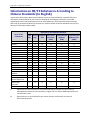
1
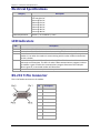
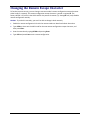
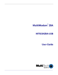
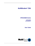
Data/Fax Industrial Temperature Modem MT5634IND User Guide Copyright and Technical Support MultiModem IND User Guide MT5634IND S000369C Rev. F Copyright This publication may not be reproduced, in whole or in part, without prior expressed written permission from Multi-Tech Systems, Inc. All rights reserved. Copyright © 2007-2012 Multi-Tech Systems, Inc. Multi-Tech Systems, Inc. makes no representations or warranty with respect to the contents hereof and specifically disclaims any implied warranty of merchantability or fitness for any particular purpose. Furthermore, Multi-Tech Systems, Inc. reserves the right to revise this publication and to make changes from time to time in the content hereof without obligation of Multi-Tech Systems, Inc. to notify any person or organization of such revisions or changes. Check Multi-Tech’s web site for current versions of our product documentation. Revision History Revision C Date 03/12/10 D E F 12/07/11 12/06/2012 12/12/2013 Description Added Technical Support Web Portal information. Changed the drawing of the RS-232 9-Pin Connector to a male connector. Added Receiver Sensitivity to the Technical Specifications. Removed CD references; added information on Installation Resources website Updated RoHS. UL translations. Patents This device is covered by one or more of the following patents: 6,031,867; 6,012,113; 6,009,082; 5,905,794; 5,864,560; 5,815,567; 5,815,503; 5,812,534; 5,809,068; 5,790,532; 5,764,628; 5,764,627; 5,754,589; 5,724,356; 5,673,268; 5,673,257; 5,644,594; 5,628,030; 5,619,508; 5,617,423; 5,600,649; 5,592,586; 5,577,041; 5,574,725; 5,559,793; 5,546,448; 5,546,395; 5,535,204; 5,500,859; 5,471,470; 5,463,616; 5,453,986; 5,452,289; 5,450,425; D353,598; 5,355,365; 5,309,562; 5,301,274. Other patents pending. Trademarks Multi-Tech, the Multi-Tech logo, and MultiModem are registered trademarks of Multi-Tech Systems, Inc. All other brand and product names mentioned in this publication are trademarks or registered trademarks of their respective companies. Contacting Multi-Tech Knowledge Base The Knowledge Base provides immediate access to support information and resolutions for all Multi-Tech products. Visit http://www.multitech.com/kb.go. Installation Resources To download manuals, firmware, and software, visit http://www.multitech.com/setup/product.go. Support Portal To create an account and submit a support case directly to our technical support team, visit: https://support.multitech.com Technical Support Business Hours: M-F, 9am to 5pm CT Country Europe, Middle East, Africa: U.S., Canada, all others: By Email [email protected] [email protected] By Phone +(44) 118 959 7774 (800) 972-2439 or (763) 717-5863 World Headquarters Multi-Tech Systems, Inc. 2205 Woodale Drive Mounds View, Minnesota 55112 Phone: 763-785-3500 or 800-328-9717 Fax: 763-785-9874 Warranty To read the warranty statement for your product, please visit: http://www.multitech.com/warranty.go 2 MT5634IND User Guide Chapter 1 – Description and Specifications .........................................................................................5 MultiModem Package Contents....................................................................................................5 AC-Powered Version ........................................................................................................................ 5 DC-Powered Version ........................................................................................................................ 5 AT and Fax Commands .................................................................................................................5 Telecom Safety Warnings .............................................................................................................5 Technical Specifications and Features ...........................................................................................6 Electrical Specifications ................................................................................................................8 LED Indicators ..............................................................................................................................8 RS-232 9-Pin Connector ................................................................................................................8 Using the MultiModem IND on a Leased-Line ...............................................................................9 Chapter 2 – Installation .................................................................................................................... 10 Mounting the Modem (Optional) ............................................................................................... 10 Connecting the Modem to Your System ...................................................................................... 10 Downloading Drivers.................................................................................................................. 11 Installing the Modem Driver ....................................................................................................... 12 Configuring the Modem for Your Country or Region.................................................................... 14 Using the Global Wizard ................................................................................................................ 14 Installing the Global Wizard ........................................................................................................... 14 Selecting the Country through the Global Wizard ......................................................................... 15 Using AT Commands to set Country or Region .............................................................................. 15 Chapter 3 – Remote Configuration.................................................................................................... 16 Basic Procedure ......................................................................................................................... 16 Changing the Setup Password .................................................................................................... 16 Changing the Remote Escape Character ...................................................................................... 17 Chapter 4 – Callback Security ........................................................................................................... 18 Changing the Setup Password .................................................................................................... 18 Turning Callback Security On and Off .......................................................................................... 18 Setting Callback Security Message Parity .................................................................................... 19 Assigning Callback Passwords and Phone Numbers ..................................................................... 19 Calling Procedures ..................................................................................................................... 20 Password-Only Callback ................................................................................................................. 20 MT5634IND User Guide 3 Contents Number-Entry Callback .................................................................................................................. 20 Extension-Entry Callback................................................................................................................ 21 Direct Connection .......................................................................................................................... 21 Callback Security Commands ......................................................................................................... 22 Chapter 5 – Troubleshooting ............................................................................................................ 23 None of the LEDs Lights .............................................................................................................. 23 Modem Does Not Respond to Commands................................................................................... 23 Modem Cannot Connect When Dialing ....................................................................................... 24 Modem Disconnects while Online .............................................................................................. 25 Modem Cannot Connect when Answering .................................................................................. 25 File Transfer Is Slow ................................................................................................................... 26 Data is Lost ................................................................................................................................ 26 Garbage Characters on the Monitor............................................................................................ 26 Modem Doesn’t Work with Caller ID .......................................................................................... 27 Fax and Data Software Can’t Run at the Same Time .................................................................... 27 Appendix A – Flash Upgrade ............................................................................................................. 28 Appendix B – Regulatory Compliance ............................................................................................... 29 Telecom Requirements for the United States .............................................................................. 29 FCC Part 15 Regulation .................................................................................................................. 29 EMC, Safety, and R&TTE Directive Compliance ............................................................................ 29 International Modem Restrictions .............................................................................................. 29 Industry Canada ......................................................................................................................... 30 New Zealand Telecom Warning Notice ....................................................................................... 30 South African Statement ............................................................................................................ 31 Information on HS/TS Substances According to Chinese Standards (in English) ............................ 32 Information on HS/TS Substances According to Chinese Standards (in Chinese) ........................... 33 Restriction of the Use of Hazardous Substances (RoHS) ............................................................... 34 Waste Electrical and Electronic Equipment Statement ................................................................ 35 WEEE Directive............................................................................................................................... 35 Instructions for Disposal of WEEE by Users in the European Union.............................................. 35 Index ............................................................................................................................................... 36 4 MT5634IND User Guide This guide describes how to set up and use your Multi-Tech MultiModem® IND. MultiModem Package Contents AC-Powered Version ● One MT5634IND industrial data/fax modem ● One mounting bracket ● RS-232 serial cable ● One RJ-11 phone cable ● One universal power supply with power cord DC-Powered Version ● One MT5634IND industrial data/fax modem ● One mounting bracket ● RS-232 serial cable ● One RJ-11 phone cable ● One fused power cable AT and Fax Commands AT commands and fax commands for the MT5634IND modem are published in separate Reference Guides. To download these documents, go to http://www.multitech.com/setup/product.go and select your model from the Product drop down list. Telecom Safety Warnings Before servicing, disconnect this product from its power source and telephone network. Also: Never install telephone wiring during a lightning storm. ● Never install a telephone jack in wet locations unless the jack is specifically designed for wet locations. ● Use this product with UL and cUL listed computers only. ● Never touch uninsulated telephone wires or terminals unless the telephone line has been disconnected at the network interface. ● Use caution when installing or modifying telephone lines. ● Avoid using a telephone during an electrical storm. There may be a remote risk of electrical shock from lightning. ● Do not use a telephone in the vicinity of a gas leak. CAUTION: To reduce the risk of fire, use only 26 AWG or larger UL Listed or CSA Certified telecommunication line cord. ● MT5634IND User Guide 5 Chapter 1 — Description and Specifications Avertissements de sécurité télécom Avant de l'entretien, débrancher ce produit de son réseau d'alimentation et de téléphone. également: ● ● ● ● ● ● ● Ne jamais installer du câblage téléphonique pendant un orage électrique. Ne jamais installer de prises téléphoniques à des endroits mouillés à moins que la prise ne soit conçue pour de tels emplacements. Utilisez ce produit avec UL et cUL ordinateurs répertoriés seulement. Ne jamais toucher fils ou des bornes téléphoniques non isolés à moins que la ligne téléphonique n'ait été déconnectée au niveau de l'interface réseau. Faire preuve de prudence au moment d'installer ou de modifier des lignes téléphoniques. Éviter d'utiliser le téléphone pendant un orage électrique. Il peut y avoir un risque de choc électrique causé par la foudre. N'utilisez pas un téléphone à proximité d'une fuite de gaz. ATTENTION: Pour réduire les risques d’incendie, utiliser uniquement des conducteurs de télécommunications 26 AWG au de section supérleure. Technical Specifications and Features Category Description Data Interface Data Rates Server-to-Client Data Rates Client-to-Server Data Rates Serial, Binary, Asynchronous Serial interface supports speeds up to56K 56K speeds when accessing a server (actual speed depends on server capabilities and line conditions) Up to 48Kbps when accessing a V.92 server (actual speed depends on server capabilities and line conditions); otherwise, the same rates as client-to-client data rates apply (see Client-to-Client Data Rates). Client-to-Client Data 33600, 31200, 28800, 26400, 24000, 21600, 19200, 16800, 14400, 12000, Rates 9600, 7200, 4800, 2400, 1200, 0-300 bps Fax Rates 33600, 31200, 28800, 26400, 24000, 21600, 19200, 16800, 14400, 12000, 9600, 7200, 4800, 2400, 300 bps Modem V.92, V.90, V.34, V.32bis, V.32, V.22bis, V.22, Bell 212A and 103/113, V.21, Compatibility V.23, V.42bis, V.44 Fax Compatibility ITU-T “Super” Group 3; Class 1.0, 2.0, 2.1; T.4; T.30; V.21; V.27ter; V.29; V.34; V.17; and TIA/EIA Class 1, 2; TR29.2 Error Correction V.42 Data Compression V.44, V.42bis Flow Control XON/XOFF; hardware (RTS/CTS) Transmit Level -13 dBm Receiver Sensitivity -43 dBm under worst case conditions Environmental Temperature range -40C to +85C Mechanical 4.3" w x 2.4" h x 0.94" d; 4.2 oz. Dimensions & Weight (11 cm x 6.1 cm x 2.4 cm; 120 g) Command Buffer 60 characters Other Features Desktop or panel mounting Industrial chassis (a rugged, water-resistant, industrial chassis made of aluminum) Automatic fallback to slower speeds in noisy line conditions and fall-forward to faster speeds as conditions improve 6 MT5634IND User Guide Chapter 1 — Description and Specifications Category Manufacturing Information Certification Description Fully AT command compatible 2-wire leased-line support Flash memory for easy updates Callback security; Remote configuration Caller ID (in U. S.) Autodial, redial, repeat dial, dial pauses; Pulse or tone dial and touch-tone dial Dial tone and busy signal detection for reliable call progress reporting Nonvolatile memory for storage of custom settings and two phone numbers Call status display Auto parity and data rate selections On-screen displays for modem option parameters Trade Name MultiModem Model Number MT5634IND Registration Number The embedded SocketModem MT5634SMI is the registered part of this product: AU7USA-25814-M5-E Ringer Equivalence 0.3B Modular Jack (USOC) RJ11 EMC Safety Approvals: FCC Part 15 Class B – Emissions for U.S.A. and Canada EN55022 Class B – Emissions for EU countries. Needed for CE marking EN55024 – Immunity for EU countries. Needed for CE marking EN61000-6-2 – Immunity for industrial environments Safety Certifications: UL60950-1 – U.S.A. and Canada Safety EN60950-1 – Safety for EU countries. Needed for CE marking GR1089 – Clause 4 NEBS Tested Warranty MT5634IND User Guide Reliability: Temperature Range: -40C to +85C EN60068-2-6 – Vibration 10 to 500 Hz sine vibration 5g EN60068-2-30 – Temp/Humidity Damp Heat cycling EN60068-2-1 – Cold (-40C) EN60068-2-2 – Dry Heat (+85C) EN60068-2-14 – Change of Temperature (-40C to +85C) IEC 68-2-27 – Shock – 3 shocks/3mS duration 50g 2 years 7 Chapter 1 — Description and Specifications Electrical Specifications Category Power Consumption Power Requirements Description Typical: 155 mA (.945 W @ 9V DC) 180 mA maximum 155 mA @ 6V DC 96 mA @ 10V DC 68 mA @ 15V DC 54 mA @ 20V DC 38 mA @ 30V DC 30 mA @ 40V DC 26 mA @ 48V DC 6V DC +/- 5% to 48V DC +/- 10% LED Indicators LED TD RD CD TR PWR Description Transmit Data. This LED is lit when modem is transmitting data to another modem. Receive Data. This LED is lit when the modem receiving data from another modem. Carrier Detect. This LED is lit when the modem detects a valid carrier signal from another modem. It is on when the modem is communicating with the other modem and off when the link is broken. Terminal Ready. (Also called Data Terminal Ready.) This LED indicates the PC is turned on and ready to communicate. This LED is lit when a data communications program initializes the modem. It goes off when the communications program disconnects the COM port. When is goes off, a connected modem will disconnect. Power. This LED Indicates the presence of DC power when lit. RS-232 9-Pin Connector This is the female connector on the modem. Pin 8 Description 1 CD 2 TX Data 3 RX Data 4 DTR 5 Ground 6 DSR 7 CTS 8 RTS 9 RI MT5634IND User Guide Chapter 1 — Description and Specifications Using the MultiModem IND on a Leased-Line The MultiModem IND can be used on a two-wire leased line. A leased line is a private, permanent phone connection between two points. Unlike a dialup connection, a leased line is always active. The modems automatically connect when they are attached to the line and are turned on. Because a leased line is always active, one of the two modems on the line must be configured as the originate modem and the other as the answer modem; however, it does not matter which is which. In the event of an interruption, leased-line modems automatically reconnect when the data line or power is restored. You must enter these commands in your communication program’s terminal window. 1. Connect a modular phone cable to the LINE jack. Connect the other end of the cable to a two-wire lease-line jack or terminals supplied by the phone company. 2. Turn on the modem. 3. Use the following AT command to configure a modem as the originating modem: AT&L1&W for L-L Orig 4. Use the following AT command to configure a modem as the answering modem: AT&L2&W for L-L Ans 5. MT5634IND User Guide 9 Chapter 2 — Installation Mounting the Modem (Optional) The MT5634IND is design to be used on the desktop or to be panel-mounted. For panel-mounting, the modem is usually mounted against a flat surface using two screws. 1. Drill two mounting holes at the desired location. The mounting holes must be separated by 4 15/16 inches center-to-center. Screw Separation 41516 inches R Industrial Modem IND 2. Slide the mounting brackets through the slot on the back of the chassis. 3. Attach the modem to the surface with two screws. Connecting the Modem to Your System 1. Turn off your computer. 2. Plug one end of the serial cable into the RS-232 connector on the modem, and plug the other end into a serial port connector on your computer, such as COM1 or COM2. 3. Plug one end of the phone cable into the MT5634IND LINE jack and the other end into a phone line wall jack. 4. Connect to AC or DC power as follows: a. AC Power Plug the power supply cable with attached transformer block into the power connector on the MultiModem. Then plug the AC cord receptacle into the transformer block, and plug the other end of the of the AC cord into a power outlet or power strip. 10 MT5634IND User Guide Chapter 2 — Installation Note: Use only the power supply supplied with the MT5634IND. Use of any other power supply will void the warranty and could damage the modem. b. DC Power Use the fused cable in place of the Universal Power Supply and the AC Power Cord. This requires a 313000 Series fuse (length: 1.25” or 31.75mm; diameter: 0.25” or 6.35mm). Plug the fused cable into the power connector on the MultiModem. Then attach the two wires at the other end of the fused cable to a DC power source. Fused Cable Fused Cable Connection 5. Turn on your computer. Downloading Drivers 1. Go to http://www.multitech.com/setup/product.go and select your model from the Product drop down list. 2. Click Drivers. 3. Click the link for the driver for your operating system. 4. Open the zip file and extract the files to a folder in your Program directory. Note: To select the correct drivers, you will need to know if you have a 32-bit or 64-bit operating system. If you do not know which version you have, Microsoft’s Knowledge Base has steps for identifying the version. MT5634IND User Guide 11 Chapter 2 — Installation Installing the Modem Driver If you use a different operating system, such as Unix or Macintosh, see the README.TXT file in the driver zip file. 1. Login as an administrator. Note: Installing a device driver modifies your system. For this reason, you must have administration rights to install the driver. If you do not have administrator rights, find someone in your organization with this authorization. 2. Plug in your modem. Windows attempts to find drivers for the new hardware. 3. Click Start | Control Panel and select Phone & Modem. If Phone & Modem is not listed, change your Control Panel view to show icons (Windows 7) or classic view (Windows XP, Vista). 4. Click Add. 5. Select Don’t detect my modem; I will select it from a list and click Next. 12 MT5634IND User Guide Chapter 2 — Installation 6. Select Have Disk. 7. Browse to the driver INF file that you saved to your computer and click Next. 8. Select the MultiTech MT5634IND-V92-IND driver and click Next. MT5634IND User Guide 13 Chapter 2 — Installation 9. Select the port where you want to install the modem and click Next. With some Windows versions, a Windows Logo testing screen appears. Click Continue Anyway. 10. Click Finish to exit. Configuring the Modem for Your Country or Region Different countries have different requirements for how modems must function. Before using your modem, configure it for country/region in which you are using it. You can use either the Global Wizard or AT Commands to configure the modem for your country. Using the Global Wizard If using your modem with a Windows operating system, use the Global Wizard software to set the country. This is available through the Multi-Tech Installation Resources site. Installing the Global Wizard 1. Go to http://www.multitech.com/setup/product.go and select your model from the Product drop down list. 2. Click Software. 14 MT5634IND User Guide Chapter 2 — Installation 3. Click Global Wizard link. 4. Click Run twice. The Global Wizard installer launches. 5. Click Next. 6. Click Yes. 7. Click Next. 8. Click Finish. This completes the Global Wizard installation. Selecting the Country through the Global Wizard 1. Click Start | All Programs |Global Wizard and select Global Wizard. The Global Wizard opens. 2. Click Next. The Global Wizard searches for your modems and identifies them. 3. Click Next. Select a modem to configure. 4. Click Next. 5. Select the country in which the modem will be used and click Next. 6. Review your choice of country. If it is correct, click Next to configure the modem. 7. When Global Wizard announces that the parameters have been set, click Finish to exit. Using AT Commands to set Country or Region Non-Windows users can configure the modem using AT commands. You must enter these commands in your communication program’s terminal window. To configure the country/region code, the initialization string must contain the AT command for your specific country or region. 1. Run a communications program, such as HyperTerminal. 2. Type AT%T19,0,nn, where nn is the country/region code in hexadecimal notation. 3. Click Enter. The message OK displays. 4. To verify that the correct country/region has been configured, type: ATI9 and click Enter. 5. The country/region code displays, for example: Country/Region Euro/NAM AT Command (hexadecimal) AT%T19,0,34 (default) Result code (decimal) 52 A list of country/region codes can be found on the Multi-Tech Web site at http://www.multitech.com/global/approvals.go. MT5634IND User Guide 15 Chapter 3 —Remote Configuration Remote configuration is a network management tool that allows you to configure MT5634IND modems anywhere in your network from one location. With password-protected remote configuration, you can issue AT commands to a remote modem for maintenance or troubleshooting as if you were on site. Basic Procedure Use the following steps when the connection is established by the local or the remote modem. Note: The remote computer must be running and a communication program must be ready for a data connection, which will be indicated by a lighted TR indicator on the front of the modem. 1. Establish a data connection with a remote MT5634IND modem. 2. Send three remote configuration escape characters followed by AT and the setup password, and press Enter. For example, %%%ATMTSMODEM. You have four tries to enter the correct password before being disconnected. If the password is correct, the remote modem responds with OK. 3. Send AT commands to configure the remote modem. Refer to the AT Command Guide for more information. 4. Save the new configuration by typing AT&W0 and pressing Enter. 5. Type ATO and press Enter to exit remote configuration. You can now break the connection in the normal way. Changing the Setup Password Multi-Tech modems are shipped with a default setup password (MTSMODEM). Because anyone who has the User Guide knows the default setup password, you should change the password. 1. Open a data communications program such as HyperTerminal. 2. Type AT#SMTSMODEM (or AT#Sxxxxxxxx if you have replaced the MTSMODEM password with xxxxxxxx) and press Enter. The modem responds with OK if the setup password is correct and ERROR if it is wrong. 3. Type AT#S=xxxxxxxx, where xxxxxxxx stands for the password, and then press Enter. The password can include any keyboard character, and can be up to eight characters long. The modem responds with OK. The new password is saved automatically. Caution: 16 Passwords are case-sensitive. MT5634IND User Guide Changing the Remote Escape Character To further improve security, you can change a remote modem’s remote configuration escape character either locally or remotely. The remote configuration escape character is stored in register S9. The factory default is 37, which is the ASCII code for the percent character (%). Setting S9 to 0 (zero) disables remote configuration entirely. Caution: If you do this remotely, you won’t be able to change it back remotely. 1. Establish a remote configuration link with the remote modem as described in Basic Procedure. 2. Type ATS9=n, where n is the ASCII code for the new remote configuration escape character, and then press Enter. 3. Save the new value by typing AT&W and pressing Enter. 4. Type ATO and press Enter to exit remote configuration. MT5634IND User Guide 17 Callback security protects your network from unauthorized access and helps control long-distance costs. When you enable callback security, all callers must enter a password. When the modem receives a valid password, it hangs up and returns the call by dialing a phone number that is stored with the password. The person called back must then enter the password a second time to establish a connection. Store up to 30 callback passwords and dialing strings in the modem. Each dialing string can be up to 35 characters long and can contain commands as well as phone numbers. For mobile callers, program the dialing string to allow the caller to bypass the stored callback number by entering a temporary callback number, to enter an extension at the callback number, or to make a direct connection without callback. For local security, the passwords and dialing strings stored in the modem are protected from tampering by a setup password, which you should change when you set up the modem. You can further protect the modem against tampering by disabling its ability to respond to most AT commands. To check for attempted break-ins, you can request the modem to display the number of failed password attempts. Changing the Setup Password Your modem was shipped with a default setup password (MTSMODEM). The same password is used for both callback security and remote configuration. Because anyone who has access to this guide has access to the default password, you should change the password during your initial setup. 1. Open a data communications program such as HyperTerminal. 2. Type AT#SMTSMODEM (or AT#Sxxxxxxxx if you have replaced the MTSMODEM password with xxxxxxxx) and press Enter. The modem responds with OK if the setup password is correct, and ERROR if it is wrong. 3. Type AT#S=xxxxxxxx, where xxxxxxxx stands for the password, and then press Enter. The password can include any keyboard character, and can be up to eight characters long. The modem responds with OK. The new password is saved automatically. Caution: Passwords are case-sensitive. Turning Callback Security On and Off Callback security must be turned on to enter many callback security commands. 1. Open a data communications program such as HyperTerminal. 2. In the terminal window, type AT#Sxxxxxxxx, where xxxxxxxx is your password. Press Enter. The modem responds with OK if the setup password is correct and ERROR if it is wrong. 3. Type one of the following commands: 18 ● To turn off callback security, type AT#CBS0 and press Enter. Callers no longer need a password to connect to the modem, the modem is unable to call them back, and the stored dialing command locations 0–3 become available. ● To turn on both local and remote callback security, type AT#CBS1. Press Enter. With local security turned on, you must enter the setup password before you can enter any AT command except the AT, ATIn, and AT#Sxxxxxxxx commands. MT5634IND User Guide Chapter 4 —Callback Security ● To turn on remote callback security only, type AT#CBS2 and press Enter. With remote callback security turned on, each caller is asked to enter a password, is called back, and then is asked to enter the password again before a connection can be made. Also, dialing command locations 0–3 for use with the DS=y dialing command are replaced by callback dialing command locations 0–29. ● To temporarily disable callback security if the modem is set to #CBS1 or #CBS2 (for instance, to call another modem), type AT#CBS3 and press Enter. The modem returns to its original setting when you issue the hangup command (+++ATH) or the modem is reset. If a remote modem breaks the connection, callback security remains disabled. Setting Callback Security Message Parity The password prompt and messages parity must match the parity of the computer to which the modem is connected. 1. Open a data communications program, such as Hyperterminal. 2. In the terminal window, type AT#Sxxxxxxxx, where xxxxxxxx is your password. Press Enter. The modem responds with OK if the setup password is correct and ERROR if it is wrong. 3. The modem’s parity default value is No parity (AT#CBP0). To change the modem’s default to use even parity, type AT#CBP2. Press Enter. For odd parity, type AT#CBP1. Press Enter. 4. To store the new parity value, type AT&W. Press Enter. Assigning Callback Passwords and Phone Numbers 1. Open a data communications program, such as HyperTerminal. 2. In the terminal window, type AT#Sxxxxxxxx, where xxxxxxxx is your password. Press Enter. The modem responds with OK if the setup password is correct and ERROR if it is wrong. 3. Enable callback security by typing AT#CBS1 or AT#CBS2 and pressing Enter. 4. To store a callback passwordfor the first callback memory location, type AT#CBN0=xxxxxxxx, where xxxxxxxx is the first password. Press Enter. ● The password must be unique, must be six to eight characters in length, and must not contain a + or - character. ● Increment memory location number by one to save to additional memory locations. For example, to store password for the second callback memory location, type AT#CBN1=xxxxxxxx, where xxxxxxxx is the second password. 5. Repeat as many times as necessary, up to memory location 29, until all passwords are entered. 6. To store a callback phone number in the first memory location, type AT&Z0=[+][-]ATxxxxxxxx[,???], where xxxxxxxx is the dialing string. Press Enter. ● The phone number must be preceded by DT for tone dialing or DP for pulse dialing. ● The dialing string can also include other AT commands, for example: AT&Z0=+ATM0DT5551212. MT5634IND User Guide 19 Chapter 4 —Callback Security ● Up to 35 characters can be used. The +, -, and ??? characters are optional: + Number entry Enables a mobile caller to enter his current phone number for callback. Direct connection Enables a caller to choose direct connection without being called back. ,??? Extension entry Must be used with the + command. Enables a caller to enter an extension number for callback. The number of ? characters must equal the number of digits in the extension. ● ● Increment the memory location number by one to save to additional memory locations. For example, to store a callback phone number in the second memory location, type AT&Z1=[+][]ATxxxxxxxx[,???], where xxxxxxxx is the dialing string. 7. Repeat, through memory location 29, until all dialing strings are entered. 8. To review your entries, type AT&V and press Enter. Calling Procedures Use the following procedures to call a modem that has callback security enabled. Note that autoanswer must be enabled on the calling modem (S0=1). Password-Only Callback Use this procedure when calling from a fixed location. 1. Use a data communications program to dial the number of the callback modem. When the connection is established, the callback modem responds with the following message: Password> 2. Type the password for your modem’s phone number. Press Enter. You have three attempts or one minute to enter a valid password. If the password is valid, the following message appears, and the modems disconnect: OK Disconnecting After the delay specified by the #CBDn command, the callback modem calls the number associated with the password. If the callback modem is unable to establish a connection, it tries again, up to the number of attempts specified by the #CBAn command. After the modems reconnect, the following message reappears: Password> 3. Type the same password you used to initiate the call. You have three attempts to enter the password, after which you will be disconnected. If the password is valid, the following message appears and the modems establish a working connection: OK Connecting Number-Entry Callback Use this procedure when calling from a phone number that is different from the one stored with the password. The password must be set up for optional number-entry callback. 1. Use a data communications program to dial the number of the callback modem. When the connection is established, the callback modem responds with the following message: Password> 2. 20 Type a number-entry password, press the plus key (+), type ATDT and the number to call back to, and press Enter. You have three attempts or one minute to enter a valid password. MT5634IND User Guide Chapter 4 —Callback Security Note: Include the long distance and area codes if they are needed. If the password is valid, the following message appears, and the modems disconnect: OK Disconnecting 3. After the delay specified by the #CBDn command, the callback modem calls the number that you entered after the + character. If the callback modem is unable to establish a connection, it tries again, up to the number of attempts specified by the #CBAn command. After the modems reconnect, the following message reappears: Password> 4. Type the same password you used to initiate the call. You are allowed three attempts to enter the password, after which you will be disconnected. If the password is valid, the following message appears and the modems establish a working connection: OK Connecting Extension-Entry Callback Use this procedure when calling from an extension at the callback number. The password that you use must be set up for an optional extension-entry callback. 1. Use a data communications program to dial the number of the callback modem. When the connection is established, the callback modem responds with the following message: Password> 2. Type an extension-entry password, press the plus key (+), type the extension to call back to, and press Enter. You have three attempts or one minute to enter a valid password. If the password is valid, the following message appears, and the modems disconnect: OK Disconnecting 3. After the delay specified by the #CBDn command, the callback modem calls the extension that you entered after the + character. If the callback modem is unable to establish a connection, it tries again, up to the number of attempts specified by the #CBAn command. After the modems reconnect, the following message reappears: Password> 4. Type the same password you used to initiate the call. You are allowed three attempts to enter the password. After that, you will be disconnected. If the password is valid, the following message appears, and the modems establish a working connection: OK Connecting Direct Connection Use this procedure when you want to connect without first being called back. The password that you use must be set up for an optional direct connection. 1. Use a data communications program to dial the number of the callback modem. When the connection is established, the callback modem responds with the following message: Password> 2. Type a direct connection password, press the - key, and then press Enter. You have three attempts or one minute to enter a valid password. If the password is valid, the following message appears and the modems establish a working connection: OK Connecting Note: You can make all calls direct connect regardless of whether the password or phone number has the - character by using the %H1 command MT5634IND User Guide 21 Chapter 4 —Callback Security Callback Security Commands The AT Commands related to Callback to Security are included in the AT Commands Reference Guide. 22 MT5634IND User Guide Chapter 5 – Troubleshooting If you are unable to make a successful connection, or if you experience data loss or garbled characters during your connection, check the following before calling Technical Support. None of the LEDs Lights When you turn on the modem, the LED indicators on the front panel should flash briefly as the modem runs a self-test. If the LEDs remain off, the modem is probably not receiving power. ● Make sure that the modem’s power switch is on. If the modem is plugged into a power strip, make sure the power strip is plugged in and its power switch is on. ● Make sure the power supply is firmly connected to the modem and the power supply’s power cord is firmly connected to both to the power supply and the wall outlet or power strip. ● If the power strip is on and the modem switch is on, try moving the power supply to another outlet on the power strip. ● Test that the outlet is live by plugging another device, such as a lamp, into it. ● The modem or power supply may be defective. If you have another Multi-Tech modem, try swapping modems. If the problem goes away, the first modem or power supply might be defective. Call Technical Support for assistance. CAUTION: Do not replace the power supply with one designed for another product; doing so can damage the modem and void your warranty. ATTENTION: Ne remplacent pas le bloc d'alimentation avec un design pour un autre produit; Cela peut endommager le modem et annuler votre garantie. Modem Does Not Respond to Commands ● Make sure the modem is plugged in and turned on. ● Make sure you are issuing the modem commands from data communication software, either manually in terminal mode or automatically by configuring the software. (You cannot send commands to the modem from the DOS prompt.) ● Make sure you are in terminal mode in your data communication program, then type AT and press Enter. If you get an OK response from your modem, your connections are good and the problem likely is in the connection setup in your communication software. ● Reset your modem by turning it off and on. If you are using DOS or Windows 3.1 communication software, make sure the initialization string includes &F as the first command, to cancel any leftover commands that could affect the modem’s operation. ● If you don’t get an OK, the problem may still be in the communication software. Make sure you have done whatever is necessary in your software to make a port connection. Not all communication programs connect to the COM port automatically. Some connect when the software loads and remain connected until the program terminates. Others can disconnect without exiting the program. The modem’s TR indicator lights to show that the software has taken control of the modem through the COM port. MT5634IND User Guide 23 Chapter 5 – Troubleshooting ● Your communication software settings may not match the physical port to which the modem is connected. The serial cable might be plugged into the wrong connector—check your computer documentation to make sure. Or the COM port you selected in your software might not be the COM port the modem is physically connected to. Compare the settings in your software to the physical connection. ● Make sure the serial cable is firmly connected at both ends. If this is first time you have used the cable? If so, it may not be wired correctly. Check the cable description on the packaging to make sure the cable is the right one for your computer. ● Peripheral expansion cards, such as sound and game cards, might include a serial port preconfigured as COM1 or COM2. The extra serial port, or the card itself, may use the same COM port, memory address, or interrupt request (IRQ) as your communication port. Be sure to disable any unused ports. ● Windows 9x: Right-click on My Computer, select Properties from the menu, click on the Device Manager tab, double-click on Ports, then double-click on the communication port your modem is connected to. In the port’s Properties sheet, click on the Resources tab to see the port’s input/output range and interrupt request. If another device is using the same address range or IRQ, it appears in the Conflicting Device List. Uncheck Use automatic settings to change the port’s settings so they do not conflict with the other device, or select the port the conflicting device is on and change it instead. If you need to open your computer to change switches or jumpers on the conflicting device, refer to the device’s documentation. ● Windows NT 4.0: To look for address or IRQ conflicts, click Start, Programs, Administrative Tools (Common), and Windows NT Diagnostics. In the Windows NT Diagnostics dialog box, click the Resources tab to see which input/output ranges and interrupt requests are in use. If you need to open your computer to change switches or jumpers on the conflicting device, refer to the device’s documentation. ● The serial port might be defective. If you have another serial port, install the modem on it, change the COM port setting in your software, and try again. ● The modem might have a problem beyond the scope of this user guide. If you have another MultiTech modem, try the other modem. If there is no problem with the other modem, call Technical Support for assistance. Modem Cannot Connect When Dialing There can be several reasons the modem fails to make a connection. Possibilities include: ● no physical connection to a phone line ● a wrong dial tone ● a busy signal ● a wrong number ● no modem at the other end ● a faulty modem, computer, or software at the other end ● incompatibility between modems ● poor line conditions Use extended result codes to narrow the list. Extended result codes are enabled by default. If they have been disabled, include V1X4 in the modem’s initialization string, or in terminal mode enter ATV1X4 and press Enter. When you dial again, the modem reports the call’s progress. ● 24 If the modem reports NO DIALTONE, check that the modem’s phone line cable is connected to both the modem’s LINE jack (not the PHONE jack) and the phone wall jack. If the cable looks secure, try MT5634IND User Guide Chapter 5 – Troubleshooting replacing it. If that doesn’t work, the problem might be in your building’s phone installation. To test the building installation, plug a phone into your modem’s phone wall jack and listen for a dial tone. If you hear a dial tone, your modem might be installed behind a corporate phone system (PBX) with an internal dial tone that sounds different from the normal dial tone. In that case, the modem might not recognize the dial tone and might treat it as an error. Check your PBX manual to see if you can change the internal dial tone. If you can’t, change your modem’s initialization string to replace X4 with X3, which will cause the modem to ignore dial tones. ● If the modem reports BUSY, the other number might be busy, in which case you should try again later. However, it might indicate that you have failed to add a 9, the prefix to the phone number if you must dial 9 for an outside line. ● If you must dial 9, include it in the modem’s dial prefix to dial it automatically, for example, ATDT9, (note the comma, which inserts a pause before the number is dialed). If you insert the 9, into the dial prefix, you do not have to include it in each directory entry. ● To change the dial prefix in HyperTerminal, select Connect from the Call menu, click Dialing Properties, and type 9 in the local and long distance boxes in How I dial from this location. ● If there is no answer on the remote end, the modem reports NO CARRIER. You might have dialed a wrong number and a person answered or you might have dialed the correct number but the other computer or software was turned off or faulty. Check the number and try again or try calling another system to make sure your modem is working. Try calling the number on your phone. If you hear harsh sounds, then another modem is answering the call, and the modems might be having problems negotiating because of modem incompatibilities or line noise. Try connecting at a lower speed. ● Poor line conditions can affect the connection. When using V.34 or V.32 client-to-client connections in poor conditions, setting S38=0 may result in better performance. Modem Disconnects while Online ● If you are not using modem on hold, call waiting can interrupt your connection when someone tries to call you. If you have call waiting service, disable it before each call. In most phone areas in North America, you can disable call waiting by preceding the phone number with *70 (verify this value with your phone company). ● Include the call waiting disabling code in the modem’s dial prefix , for example, ATDT*70, (note the comma, which inserts a pause before the number is dialed). To change the dial prefix in HyperTerminal, select Connect from the Call menu, click Dialing Properties, check This location has Call Waiting, and select the correct code for your phone service. ● If you have extension phones on the same line as your modem, you or someone else can interrupt the connection by picking up another phone. If this is a frequent problem, disconnect the extension phones before using the modem or install another phone line especially for the modem. ● Check for loose connections between the modem and the computer, the phone jack, and AC power. ● You might have had a poor connection because of line conditions or the problem might have originated on the other end of the line. Try again. ● Your ISP might have hung up on you because of lack of activity on your part or because you exceeded your time limit for the day. Try again. Modem Cannot Connect when Answering ● The default DTR Control command (&D2) inhibits autoanswer. To enable autoanswer, change DTR Control to &D0, and make sure &Q0, &Q5, or &Q6 is also set. For more information, see the &D MT5634IND User Guide 25 Chapter 5 – Troubleshooting command in the AT Commands Reference Guide. For information on changing the modem’s default configuration, see “Install and Configure Your Software” in Chapter 2. ● Autoanswer might be disabled. Turn on autoanswer in your communications program or send the command ATS0=1 (ATS0=2 if you have caller ID service) to your modem in terminal mode. File Transfer Is Slow ● If you are using a slow transfer protocol, such as Xmodem, try Zmodem or Ymodem/G instead. ● Is your line noisy? If there is static on your line, the modem has to resend many blocks of data to insure accuracy. You must have a clean line for maximum speed. ● Are you downloading a compressed file with MNP 5 hardware compression enabled? Since hardware data compression cannot compress a file already compressed by an archiving program, the transfer can be marginally slower with data compression enabled than with it disabled. ● Does your Internet service provider (ISP) use the same 56K protocol as your modem? The default setting of your modem is to connect using either the V.92 or the V.90 protocol, depending on which one the ISP’s modem is using. If your ISP uses the V.90 protocol, the maximum speed you will be able to upload at is 33,600 bps. Check with your ISP to see which protocols it supports. ● Are you trying to send a file to another client modem? If so, then your maximum possible connect speed is 33,600 bps. You can upload at speeds up to 48,000 bps only when connected to an ISP that supports the V.92 protocol. ● Try entering the I11 command in online mode or the &V command in command mode to display information about the last connection, making a screen print of the connection statistics, and checking for parameters that might be unacceptable. Data is Lost ● If you are using data compression and a high speed serial port, set the serial port baud rate to two to six times the data rate. ● Make sure the flow control method you selected in software matches the method selected in the modem. ● Try entering the I11 command in online mode or the &V command in command mode to display information about the last connection, making a screen print of the connection statistics, and checking for parameters that might be unacceptable. Garbage Characters on the Monitor ● Your computer and the remote computer might be set to different word lengths, stop bits, or parities. If you have connected at 8-N-1, try changing to 7-E-1, or vice-versa, using your communication software. ● You might be experiencing line noise. Enable error correction, if it is disabled, or hang up and call again; you might get a better connection the second time. ● At speeds above 2400 bps, the remote modem might not use the same transmission or error correction standards as your modem. Try connecting at a slower speed or disabling error correction. (With no error correction, however, line noise can cause garbage characters.) 26 MT5634IND User Guide Chapter 5 – Troubleshooting ● Try entering the I11 command in online mode or the &V command in command mode to display information about the last connection, making a screen print of the connection statistics, and checking for parameters that might be unacceptable. Modem Doesn’t Work with Caller ID ● Caller ID information is transmitted between the first and second rings, so if autoanswer is turned off (S0=0) or if the modem is set to answer after only one ring (S0=1), the modem will not receive Caller ID information. Check your initialization string, and if necessary change it to set the modem to answer after the second ring (S0=2). ● Make sure that you have Caller ID service from your phone company. Fax and Data Software Can’t Run at the Same Time ● Communication devices can be accessed by only one application at a time. In Windows 95 and higher, you can have data and fax communication applications open at the same time, but they cannot use the same modem at the same time. MT5634IND User Guide 27 Chapter 5 – Troubleshooting Your modem is controlled by semi-permanent firmware, which is stored in flash memory. Multi-Tech's firmware remains stored in memory when the modem is turned off and can be upgraded as new features are added. Multi-Tech's Flash Wizard can be downloaded from Multi-Tech’s FTP site. Use this Flash Wizard for upgrading your firmware. Documentation for using the Flash Wizard is included with the wizard. Flash Wizard Software for Windows: ftp://ftp.multitech.com/utilities/flashwizard/ Flash Wizard Software for Linux: http://mtflashwiz.sourceforge.net/ 28 MT5634IND User Guide Telecom Requirements for the United States FCC Part 15 Regulation This equipment has been tested and found to comply with the limits for a Class B digital device, pursuant to part 15 of the FCC Rules. These limits are designed to provide reasonable protection against harmful interference in a residential installation. This equipment generates, uses, and can radiate radio frequency energy and, if not installed and used in accordance with the instructions, may cause harmful interference to radio communications. However, there is no guarantee that interference will not occur in a particular installation. If this equipment does cause harmful interference to radio or television reception, which can be determined by turning the equipment off and on, the user is encouraged to try to correct the interference by one or more of the following measures: Reorient or relocate the receiving antenna. ● Increase the separation between the equipment and receiver. ● Connect the equipment into an outlet on a circuit different from that to which the receiver is connected. ● Consult the dealer or an experienced radio/TV technician for help. Warning: Changes or modifications to this unit not expressly approved by the party responsible for compliance could void the user’s authority to operate the equipment. ● EMC, Safety, and R&TTE Directive Compliance The CE mark is affixed to this product to confirm compliance with the following European Community Directives: Council Directive 2004/108/EC of 15 December 2004 on the approximation of the laws of Member States relating to electromagnetic compatibility; and Council Directive 2006/95/EC of 12 December 2006 on the harmonization of the laws of Member States relating to electrical equipment designed for use within certain voltage limits; and Council Directive 1999/5/EC of 9 March 1999 on radio equipment and telecommunications terminal equipment and the mutual recognition of their conformity. International Modem Restrictions Some dialing and answering defaults and restrictions may vary for international modems. Changing settings may cause a modem to become non-compliant with national regulatory requirements in specific countries. Also note that some software packages may have features or lack restrictions that may cause the modem to become non-compliant. MT5634IND User Guide 29 Appendix B — Regulatory Compliance Industry Canada This Class B digital apparatus meets all requirements of the Canadian Interference-Causing Equipment Regulations. Cet appareil numérique de la classe B respecte toutes les exigences du Reglement Canadien sur le matériel brouilleur. This device complies with Industry Canada RSS Appliance radio exempt from licensing. The operation is permitted for the following two conditions: the device may not cause harmful interference, and 2. the user of the device must accept any interference suffered, even if the interference is likely to jeopardize the operation. Le présent appareil est conforme aux CNR d'Industrie Canada applicables aux appareils radio exempts de licence. L'exploitation est autorisée aux deux conditions suivantes: 1. l'appareil ne doit pas produire de brouillage, et 2. l'utilisateur de l'appareil doit accepter tout brouillage radioélectrique subi, même si le brouillage est susceptible d'en compromettre le fonctionnement. 1. New Zealand Telecom Warning Notice 1. The grant of a Telepermit for any item of terminal equipment indicates only that Telecom has accepted that the item complies with minimum conditions for connection to its network. It indicates no endorsement of the product by Telecom, nor does it provide any sort of warranty. Above all, it provides no assurance that any item will work correctly in all respects with another item of Telepermitted equipment of a different make or model, nor does it imply that any product is compatible with all of Telecom’s network services. This equipment is not capable under all operating conditions of correct operating conditions of correct operation at the higher speed which it is designated. 33.6 kbps and 56 kbps connections are likely to be restricted to lower bit rates when connected to some PSTN implementations. Telecom will accept no responsibility should difficulties arise in such circumstances. 2. Immediately disconnect this equipment should it become physically damaged, and arrange for its disposal or repair. 3. This modem shall not be used in any manner which could constitute a nuisance to other Telecom customers. 4. This device is equipped with pulse dialing, while the Telecom standard is DTMF tone dialing. There is no guarantee that Telecom lines will always continue to support pulse dialing. Use of pulse dialing, when this equipment is connected to the same line as other equipment, may give rise to 'bell tinkle' or noise and may also cause a false answer condition. Should such problems occur, the user should NOT contact the Telecom Faults Service. The preferred method of dialing is to use DTMF tones, as this is faster than pulse (decadic) dialing and is readily available on almost all New Zealand telephone exchanges. 5. Warning Notice: No '111' or other calls can be made from this device during a mains power failure. 6. This equipment may not provide for the effective hand-over of a call to another device connected to the same line. 30 MT5634IND User Guide Appendix B — Regulatory Compliance 7. Some parameters required for compliance with Telecom’s Telepermit requirements are dependent on the equipment (PC) associated with this device. The associated equipment shall be set to operate within the following limits for compliance with Telecom’s Specifications: For repeat calls to the same number: ● There shall be no more than 10 call attempts to the same number within any 30 minute period for any single manual call initiation, and ● The equipment shall go on-hook for a period of not less than 30 seconds between the end of one attempt and the beginning of the next attempt. For automatic calls to different numbers: ● 8. The equipment shall be set to ensure that automatic calls to different numbers are spaced such that there is no less than 5 seconds between the end of one call attempt and the beginning of another. For correct operation, total of the RN’s of all devices connected to a single line at any time should not exceed 5. South African Statement This modem must be used in conjunction with an approved surge protection device. MT5634IND User Guide 31 Appendix B — Regulatory Compliance Information on HS/TS Substances According to Chinese Standards (in English) In accordance with China’s Administrative Measures on the Control of Pollution Caused by Electronic Information Products (EIP) # 39, also known as China RoHS, the following information is provided regarding the names and concentration levels of Toxic Substances (TS) or Hazardous Substances (HS) which may be contained in Multi-Tech Systems Inc. products relative to the EIP standards set by China’s Ministry of Information Industry (MII). Hazardous/Toxic Substance/Elements Name of the Component Printed Circuit Boards Resistors Capacitors Ferrite Beads Relays/Opticals ICs Diodes/ Transistors Oscillators and Crystals Regulator Voltage Sensor Transformer Speaker Connectors LEDs Screws, Nuts, and other Hardware AC-DC Power Supplies Software / Documentation CDs Booklets and Paperwork Chassis Lead Mercury Cadmium Hexavalent (PB) (Hg) (CD) Chromium (CR6+) Polybrominated Polybrominated Biphenyl Diphenyl Ether (PBB) (PBDE) O X X O O O O X O O O O O O X O O O O O O O O O O O O O O O O O O O O O O O O O O O O O O O O O O O O O O O O O O O O O O O O O O O O O O O O O O O O O O O O O O O O O O O O O O O O O O O O O O O O O O O O O O O O O O O O O O O X Represents that the concentration of such hazardous/toxic substance in all the units of homogeneous material of such component is higher than the SJ/Txxx-2006 Requirements for Concentration Limits. O Represents that no such substances are used or that the concentration is within the aforementioned limits. 32 MT5634IND User Guide Appendix B — Regulatory Compliance Information on HS/TS Substances According to Chinese Standards (in Chinese) 依照中国标准的有毒有害物质信息 根据中华人民共和国信息产业部 (MII) 制定的电子信息产品 (EIP) 标准-中华人民共和国《电子信息产品污染控制管理办法》(第 39 号),也称作中国 RoHS,下表列出了 Multi-Tech Systems, Inc. 产品中可能含有的有毒物质 (TS) 或有害物质 (HS) 的名称及含量水平方面的信息。 有害/有毒物质/元素 成分名称 铅 汞 镉 多溴联苯 多溴二苯醚 (CD) 六价铬 (CR6+) (PB) (Hg) (PBB) (PBDE) 印刷电路板 电阻器 O X O O O O O O O O O O 电容器 X O O O O O 铁氧体磁环 继电器/光学部件 IC 二极管/晶体管 振荡器和晶振 调节器 电压传感器 变压器 扬声器 连接器 LED 螺丝、螺母以及其它五金件 交流-直流电源 软件/文档 CD 手册和纸页 O O O O X O O O O O O X O O O O O O O O O O O O O O O O O O O O O O O O O O O O O O O O O O O O O O O O O O O O O O O O O O O O O O O O O O O O O O O O O O O O O O O O O O O O O O 底盘 O O O O O O X 表示所有使用类似材料的设备中有害/有毒物质的含量水平高于 SJ/Txxx-2006 限量要求。 O 表示不含该物质或者该物质的含量水平在上述限量要求之内。 MT5634IND User Guide 33 Appendix B — Regulatory Compliance Restriction of the Use of Hazardous Substances (RoHS) Multi-Tech Systems, Inc. Certificate of Compliance 2011/65/EU Multi-Tech Systems confirms that its embedded products comply with the chemical concentration limitations set forth in the directive 2011/65/EU of the European Parliament (Restriction of the use of certain Hazardous Substances in electrical and electronic equipment - RoHS) These Multi-Tech products do not contain the following banned chemicals1: ● Lead, [Pb] < 1000 PPM ● Mercury, [Hg] < 1000 PPM ● Hexavalent Chromium, [Cr+6] < 1000 PPM ● Cadmium, [Cd] < 100 PPM ● Polybrominated Biphenyl, [PBB] < 1000 PPM ● Polybrominated Diphenyl Ether, [PBDE] < 1000 PPM Environmental considerations: ● Moisture Sensitivity Level (MSL) =1 ● Maximum Soldering temperature = 260C (in SMT reflow oven) 1Lead usage in some components is exempted by the following RoHS annex, therefore higher lead concentration would be found in some modules (>1000 PPM); –Resistors containing lead in a glass or ceramic matrix compound. 34 MT5634IND User Guide Appendix B — Regulatory Compliance Waste Electrical and Electronic Equipment Statement Note to OEMs: The statement is included for your information and may be used in the documentation of your final product applications. WEEE Directive The WEEE Directive places an obligation on EU-based manufacturers, distributors, retailers, and importers to take-back electronics products at the end of their useful life. A sister directive, ROHS (Restriction of Hazardous Substances) complements the WEEE Directive by banning the presence of specific hazardous substances in the products at the design phase. The WEEE Directive covers all MultiTech products imported into the EU as of August 13, 2005. EU-based manufacturers, distributors, retailers and importers are obliged to finance the costs of recovery from municipal collection points, reuse, and recycling of specified percentages per the WEEE requirements. Instructions for Disposal of WEEE by Users in the European Union The symbol shown below is on the product or on its packaging, which indicates that this product must not be disposed of with other waste. Instead, it is the user’s responsibility to dispose of their waste equipment by handing it over to a designated collection point for the recycling of waste electrical and electronic equipment. The separate collection and recycling of your waste equipment at the time of disposal will help to conserve natural resources and ensure that it is recycled in a manner that protects human health and the environment. For more information about where you can drop off your waste equipment for recycling, please contact your local city office, your household waste disposal service or where you purchased the product. July, 2005 MT5634IND User Guide 35 A Global Wizard .................................................. 14 AC power connection ....................................... 10 autoanswer ...................................................... 25 I C call waiting ....................................................... 25 callback security ............................................... 18 message parity .............................................. 19 password....................................................... 19 phone numbers............................................. 19 caller ID ............................................................ 26 carrier detect ..................................................... 8 configure modem AT commands ............................................... 15 Global Wizard ............................................... 14 country ............................................................. 14 D Data Interface .................................................... 6 Data Rates .......................................................... 6 DC power connection....................................... 10 driver download ...................................................... 11 install............................................................. 12 DTR (Data Terminal Ready) control command 25 E EMC requirements Industry Canada ............................................ 30 United States ................................................ 29 EMC safety approvals......................................... 7 F Fax Rates ............................................................ 6 FCC ................................................................... 29 Features ............................................................. 6 firmware upgrade ............................................ 28 flash upgrade ................................................... 28 Flash Wizard ..................................................... 28 front panel ....................................................... 23 G garbage characters........................................... 26 36 indicators ......................................................... 23 installation ....................................................... 10 L leased-line operation ......................................... 9 LED indicators .............................................. 8, 23 lost data ........................................................... 26 M MNP 5 data compression ................................ 26 P Package Contents .............................................. 5 password.......................................................... 18 phone line connection ..................................... 10 power connection ............................................ 10 power consumption........................................... 8 power LED .......................................................... 8 power requirements .......................................... 8 protocols .......................................................... 26 R receive data ....................................................... 8 reliability ............................................................ 7 remote configuration....................................... 16 change password .......................................... 16 escape character .......................................... 17 RoHS Compliance............................................. 34 S safety certifications ........................................... 7 Specifications ..................................................... 6 T terminal ready ................................................... 8 test modem ..................................................... 23 transmit data ..................................................... 8 U upgrade firmware ............................................ 28 MT5634IND User Guide