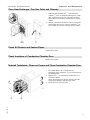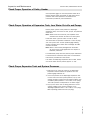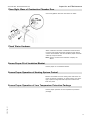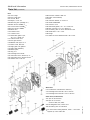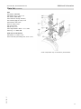
1
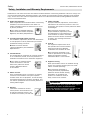
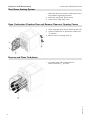
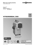
Service Instructions for use by heating contractor Vitorond 200 VD2A Series Oil-/Gas-fired boiler Heating input: 490 to 1096 MBH 144 to 321 kW VITOROND 200 Product may not be exactly as shown IMPORTANT Read and save these instructions for future reference. 5354 789 - 01 03/2015 Please file in Service Binder Safety Vitorond 200, VD2A Series Service Safety, Installation and Warranty Requirements Please ensure that these instructions are read and understood before commencing installation. Failure to comply with the instructions listed below and details printed in this manual can cause product/property damage, severe personal injury, and/or loss of life. Ensure all requirements below are understood and fulfilled (including detailed information found in manual subsections). Product documentation Read all applicable documentation before commencing installation. Store documentation near boiler in a readily accessible location for reference in the future by service personnel. For a listing of applicable literature, please see section entitled “Important Regulatory and Safety Requirements”. Licensed professional heating contractor The installation, adjustment, service and maintenance of this equipment must be performed by a licensed professional heating contractor. For information pertaining to the proper installation, adjustment, service and maintenance of this equipment to avoid formation of carbon monoxide, please see section entitled “Combustion air supply” and “Venting information” in this manual. Please see section entitled “Important Regulatory and Installation Requirements”. Contaminated air Air contaminated by chemicals can cause by-products in the combustion process, which are poisonous to inhabitants and destructive to Viessmann equipment. For a listing of chemicals which cannot be stored in or near the boiler room, please see section entitled “Mechanical Room”. in this manual. 2 Advice to owner Once the installation work is complete, the heating contractor must familiarize the system operator/ ultimate owner with all equipment, as well as safety precautions/requirements, shutdown procedure, and the need for professional service annually before the heating season begins. Warranty Information contained in this and related product documentation must be read and followed. Failure to do so renders the warranty null and void. Carbon monoxide Improper installation, adjustment, service and/or maintenance can cause flue products to flow into living space. Flue products contain poisonous carbon monoxide gas. Fresh air This equipment requires fresh air for safe operation and must be installed ensuring provisions for adequate combustion and ventilation air exist. For information pertaining to the fresh air requirements of this product, please see subsection entitled “Mechanical Room” in this manual. Equipment venting Never operate boiler without an installed venting system. An improper venting system can cause carbon monoxide poisoning. For information pertaining to venting and chimney requirements, please see section entitled “Venting Information” in this manual. All products of combustion must be safely vented to the outdoors. WARNING Installers must follow local regulations with respect to installation of carbon monoxide detectors. Follow the Viessmann maintenance schedule of the boiler in the “Service Instructions” manual. 5354 789 - 01 Safety Vitorond 200, VD2A Series Service Safety, Installation and Warranty Requirements (continued) H Fiberglass wool and ceramic fiber materials WARNING Inhaling of fiberglass wool and/or ceramic fiber materials is a possible cancer hazard. These materials can also cause respiratory, skin and eye irritation. The state of California has listed the airborne fibers of these materials as a possible cancer hazard through inhalation. When handling these materials, special care must be applied. Suppliers of ceramic fiber products recommend the following first aid measures: - Respiratory tract (nose and throat) irritation: If respiratory tract irritation develops, move the person to a dust free location. - Eye irritation: If eyes become irritated, flush immediately with large amounts of lukewarm water for at least 15 minutes. Eyelids should be held away from the eyeball to ensure thorough rinsing. Do not rub eyes. - Skin irritation: If skin becomes irritated, remove soiled clothing. Do not rub or scratch exposed skin. Wash area of contact thoroughly with soap and water. Using a skin cream or lotion after washing may be helpful. 5354 789 - 01 - Gastrointestinal irritation: If gastrointestinal tract irritation develops, move the person to a dust free environment. Suppliers of fiberglass wool products recommend the following precautions be taken when handling these materials: Precautionary measures - Avoid breathing fiberglass dust and contact with skin and eyes. - Use NIOSH approved dust/mist respirator. - Wear long-sleeved, loose fitting clothing, gloves and eye protection. - Wash work clothes separately from other clothing. Rinse washer thoroughly. - Operations such as sawing, blowing, tear-out and spraying may generate airborne fiber concentration requiring additional protection. First aid measures - If eye contact occurs, flush eyes with water to remove dust. If symptoms persist, seek medical attention. - If skin contact occurs, wash affected areas gently with soap and warm water after handling. H Hazardous materials WARNING Appliance materials of construction, products of combustion and the fuel contain alumina, silica, heavy metals, carbon monoxide, nitrogen oxides, aldehydes and/or other toxic or harmful substances which can cause serious injury or loss of life and which are known to the State of California to cause cancer, birth defects and other reproductive harm. Always use proper safety clothing, respirators and equipment when servicing or working nearby the appliance. 3 Table of Contents Vitorond 200, VD2A Series Service Page Safety Safety, Installation and Warranty Requirements..............2 Product documentation...........................................2 Licensed professional heating contractor ...................2 Contaminated air ...................................................2 Advice to owner ....................................................2 Warranty ..............................................................2 Carbon monoxide...................................................2 Fresh air ...............................................................2 Equipment venting .................................................2 Fiberglass wool and ceramic fiber materials ...............3 Suppliers of ceramic fiber products recommend the following first aid measures: ..............................3 Precautionary measures ..........................................3 First aid measures ..................................................3 Hazardous materials ...............................................3 Important Regulatory and Safety Requirements ..............6 Instructing the system user .....................................6 Initial start-up ........................................................6 Working on the equipment ......................................6 Technical literature ................................................6 General Information About these Installation Instructions .............................7 Necessary Tools .........................................................8 Tools ...................................................................8 Cleaning supplies ...................................................8 Testing/Analysis equipment.....................................8 Technical information .............................................8 Replacement parts .................................................8 Customer Site Information ...........................................9 4 5354 789 - 01 Site ......................................................................9 Boiler ...................................................................9 Burner ..................................................................9 Installing Contractor ...............................................9 Vitorond 200, VD2A Series Service Table of Contents Page Inspection and Maintenance Shut Down Heating System .......................................10 Open Combustion Chamber Door and Remove Clean-out Opening Covers .........................................10 Remove and Clean Turbulators ...................................10 Clean Heat Exchanger, Flue Gas Collar and Chimney........11 Check all Gaskets and Sealant Ropes ..........................11 Check Insulation of Combustion Chamber Door ............11 Reinstall Turbulators, Clean-out Covers and Close Combustion Chamber Door ........................................11 Check Proper Operation of Safety Header ....................12 Check Proper Operation of Expansion Tank, Low Water Cut-offs and Pumps ..................................................12 Check Proper Expansion Tank and System Pressures ....13 Clean Sight Glass of Combustion Chamber Door ..........13 Check Water Hardness..............................................13 Ensure Proper Fit of Insulation Blanket ........................13 Ensure Proper Operation of Heating System Control ..........13 Ensure Proper Operation of Low Temperature Protection Package ..................................................................13 Check Combustion Air Supply ....................................14 Check Vent System ..................................................14 Calibrate Burner .......................................................14 Two-stage burner ................................................14 Model.................................................................14 Flue gas resistance ..............................................14 Weishaupt / Riello burners.....................................15 Gas-fired ............................................................15 Oil-fired ..............................................................15 Vitorond 200 with Viessmann boiler controls ..........15 Model.................................................................15 Input ..................................................................15 Check Proper Operation of Door Safety Switch (Oil Burners Only) .....................................................15 Maintenance Schedule ..............................................16 Maintenance .......................................................16 Frequency ...........................................................16 Performed by ......................................................16 Service ...............................................................16 Additional Information Parts List.................................................................17 5354 789 - 01 Maintenance Record .................................................20 5 Safety Vitorond 200, VD2A Series Service Important Regulatory and Safety Requirements Instructing the system user Technical literature The installer of the system is responsible to ensure the system operator/ultimate owner is made familiar with the functioning of the system, its activation, and its shut-down. Note: The following topics must be covered: Proper system operation sequence. Explain the equipment as well as the need for combustion air. Demonstrate an emergency shut-down, what to do and what not. Explain that there is no substitute for proper maintenance to help ensure safe operation. Literature for the Vitorond 200 VD2A* boiler: - Technical Data Manual - Installation Instructions - Service Instructions - Operating Instructions and User’s Information Manual - Instructions of other Viessmann products utilized with this installation - Installation codes mentioned in this manual Initial start-up Note: L eave all literature at the installation site and advise the system operator/ultimate owner where the literature can be found. Contact Viessmann for additional copies. Initial start-up must be performed by a qualified heating contractor. Completion of the Maintenance Record by the heating contractor is also required. Note: The Maintenance Record is located on page 20 of this manual. Additional applicable literature: - Viessmann boiler controls manuals Working on the equipment The installation, adjustment, service, and maintenance of this boiler must be performed by a licensed professional heating contractor who is qualified and experienced in the installation, service, and maintenance of hot water boilers. There are no user serviceable parts on the boiler, burners, or control. Note: P lease carefully read this manual prior to attempting installation. Any warranty is null and void if these instructions are not followed. For information regarding other Viessmann System Technology componentry, please reference documentation of the respective product. Viessmann offers frequent installation and service seminars to familiarize our partners with our products. Please inquire. 6 5354 789 - 01 Ensure main power supply to equipment, the heating system, and all external controls has been deactivated. Close main gas supply valve. Take precautions in all instances to avoid accidental activation of power during service work. Note: The completeness and functionality of field supplied electrical controls and components must be verified by the heating contractor. This includes low water cut-offs, flow switches (if used), staging controls, pumps, motorized valves, air vents, thermostats, etc. Vitorond 200, VD2A Series Service General Information About these Installation Instructions Take note of all symbols and notations intended to draw attention to potential hazards or important product information. These include “WARNING”, “CAUTION”, and “IMPORTANT”. See below. WARNING Warnings draw your attention to the presence of potential hazards or important product information. Indicates an imminently hazardous situation which, if not avoided, could result in loss of life, serious injury or substantial product/property damage. CAUTION Cautions draw your attention to the presence of potential hazards or important product information. Indicates an imminently hazardous situation which, if not avoided, may result in minor injury or product/ property damage. IMPORTANT Helpful hints for installation, operation or maintenance which pertain to the product. This symbol indicates that additional, pertinent information is to be found. 5354 789 - 01 This symbol indicates that other instructions must be referenced. 7 General Information Vitorond 200, VD2A Series Service Necessary Tools Tools Technical information H Assortment of flathead and Phillips screwdrivers The following is a list of literature applicable to the Vitorond 200, VD2A boiler: H Pipe wrenches H Open-ended wrenches H Pipe sealant H Assortment of Allen keys H Flashlight H Approved leak detection fluid for natural gas and propane gas Cleaning supplies H Installation Instructions H Service Instructions H Operating Instructions and User’s Information Manual For installation of the heating system, please refer also to the technical literature of other System Technology devices: H Installation Instructions for Viessmann boiler control H Hand brush H Installation Instructions for Viessmann indirect-fired hot water storage tank(s) H Cleaning/service brush (supplied) H Installation Instructions for burner and accessories H Vacuum cleaner H Rags Testing/Analysis equipment (use only calibrated equipment) H Flue gas analyzer to measure % CO2 or O2 (i.e. Bacharach fluid samplers or a suitable electronic analyzer) H Multimeter to measure 0 - 120 VAC, 0 - 12 AAC, and 0 - 20 microamps DC H Smoke test gun (Bacharach) H Oil pump pressure gage Replacement parts For a complete listing of replacement components, please see Parts List starting on page 17 of these instructions. Order replacement components from your Viessmann distributor. CAUTION Use only original Viessmann components when replacing defective parts. Installation of incorrect replacement parts can cause hazardous operation and will void warranty. H Oil pump vacuum gage H Pressure gage to measure gas pressure 0 - 28 ”w.c. (a non-electric Magnehelicr pressure gage may also be used) H Carbon monoxide measuring equipment (0 - 400 ppm) H Bacharach calculator or suitable tables to calculate efficiency H Stack thermometer 0 to 500° F (0 to 260° C) 8 5354 789 - 01 H d in. NPT male to ¼ in. barb adaptor fitting, as well as tubing for pressure measurement Vitorond 200, VD2A Series Service General Information Customer Site Information Please complete the information below. Site Name: Street: City: Tel.: Boiler Mfr.: Viessmann Series: Heating Input: MBH Serial No.: Burner Mfr.: Series: Heating Input: MBH Serial No.: Installing Contractor Firm: Technician: Address: Tel.: 5354 789 - 01 Installed on: 9 Inspection and Maintenance Vitorond 200, VD2A Series Service Shut Down Heating System 1. Deactivate main power supply to heating system and secure against accidental reactivation. 2. Disconnect plug fA and lÖ from burner. 3. Close main oil or gas supply valve. Open Combustion Chamber Door and Remove Clean-out Opening Covers 1. When using a gas power burner: Disconnect gas train. 2. Loosen four M12 bolts on combustion chamber door A and open. 3. Remove clean-out opening covers B. 1. On models VD2A-125 to VD2A-195 only: Remove turbulators A and clean. 10 5354 789 - 01 Remove and Clean Turbulators Inspection and Maintenance Vitorond 200, VD2A Series Service Clean Heat Exchanger, Flue Gas Collar and Chimney 1. Clean flue gas passageways A and combustion chamber B with the supplied cleaning brush. Clean tight areas between ribs with the smaller cleaning brush. Remove combustion residues with a vacuum cleaner. 2. Remove combustion residues of chimney connection and flue gas collar via the clean-out openings C at rear of boiler (for example, using a vacuum cleaner). Check All Gaskets and Sealant Ropes Replace worn items. Check Insulation of Combustion Chamber Door Replace worn items. 5354 789 - 01 Reinstall Turbulators, Clean-out Covers and Close Combustion Chamber Door 1. On models VD2A-125 to VD2A-195 only: Completely insert turbulators B into the second flue gas passageways. 2. Tighten bolts A of combustion chamber door in a cross-wise fashion. When using a gas power burner: Connect gas train and perform necessary leak detection tests. 3. Install clean-out opening covers C. 11 Inspection and Maintenance Vitorond 200, VD2A Series Service Check Proper Operation of Safety Header Check pressure gage, air vent and pressure relief valve. Ensure pressure relief valve does not leak. Also ensure pressure relief valve operates in accordance with information provided by the manufacturer. Check Proper Operation of Expansion Tank, Low Water Cut-offs and Pumps Ensure proper system water pressure in diaphragm expansion tanks, low water cut-offs, pumps, and pressure relief valve. Note: Observe the instructions by the expansion tank manufacturer. Perform all tests on a cold system. Flush float water type low water cut-offs (if used). The usual water fill pressure is between 12 and 15 psig with the system cold. A lower pressure gage reading usually indicates loss of water due to leakage. All leaks must be corrected. Note: Refer to instructions packaged with automatic fill valve. Follow local regulations with respect to backflow preventers. If oil-lubricated pumps are used, ensure proper lubrication. If motorized zone valves are used, refer to maintenance instructions provided with zone valves. If an older non-diaphragm expansion tank is used, ensure the correct water level is present (approx. h full). Check Proper Expansion Tank and System Pressures 1. Drain system or close cap valve on the diaphragm expansion tank and reduce the pressure until the pressure gage indicates “0”. 2. If the inlet pressure of the diaphragm expansion tank is lower than the static system pressure, top up with enough nitrogen to raise the inlet pressure higher than the static system pressure 0.1 to 0.2 bar (1.5 to 3 psig). The static pressure corresponds to the static height. 12 5354 789 - 01 3. Top up with water until the filling pressure of a cool system is higher than the inlet pressure of the diaphragm expansion tank 0.1 to 0.2 bar (1.5 to 3 psig). Max. operating pressure is 5 bar (75 psig). Inspection and Maintenance Vitorond 200, VD2A Series Service Clean Sight Glass of Combustion Chamber Door Check the gaskets and hose connection for leaks. Check Water Hardness Water treatment should be considered in areas where it is known that boiler feed water contains a high mineral content and hardness. Test and establish proper chemical make-up of system water. Note: Contact a local water treatment company for advice. Ensure Proper Fit of Insulation Blanket Ensure proper fit of insulation blanket. Ensure Proper Operation of Heating System Control Remove motorized arm from mixing valve and check the motor for ease of movement. If mixing valve is not watertight, replace O-ring seals and snap the motorized arm back into place Ensure Proper Operation of Low Temperature Protection Package 5354 789 - 01 Ensure proper operation of low temperature protection package. 13 Inspection and Maintenance Vitorond 200, VD2A Series Service Check Combustion Air Supply Ensure an adequate supply of combustion and ventilation air is available. If an outside air duct is required, ensure it is installed. Note: See subsection entitled “Combustion air supply” in the Installation Instructions. Ensure that nothing is obstructing the flow of combustion and ventilation air and no chemicals, garbage, gasoline, combustible materials, flammable vapors and liquids are stored (not even temporarily) in the vicinity of the boiler. Check Vent System Ensure proper operation of the barometric draft regulator (barometric damper). Note: See Installation Instruction Supplement for Barometric Draft Regulator. Calibrate Burner See separate instructions supplied with the burner. The maximum input published for each boiler size must not be exceeded. Two-stage burner With a two-stage burner, when the boiler water temperature falls below the minimum 140º F (60º C), the burner automatically switches to the second stage (full input) to protect the boiler from the effects of dew-point condensation, i.e. condensation/corrosion. In order to provide this protection, the burner must not be limited to first stage operation during the summer months. 14 Flue gas resistance mbar “w.c. VD2A-125 0.65 0.26 VD2A-160 0.95 0.38 VD2A-195 1.0 0.40 VD2A-230 1.2 0.48 VD2A-270 1.6 0.64 5354 789 - 01 Model Inspection and Maintenance Vitorond 200, VD2A Series Service Calibrate Burner (continued) Weishaupt / Riello burners A Vitorond 200, VD2A boiler with a high-performance gas burner can achieve a combustion efficiency of up to 85.2%, and up to 87.9% if equipped with a #2 oil burner. Gas-fired 10% volume CO2, 280° F (138° C) net stack temperature, CO in ppm < 50 Oil-fired 13% volume CO2, 300° F (149° C) net stack temperature, smoke spot 0 - 1 (on the Bacharach Scale) Refer to the Installation Instructions for Oil Door Safety Switch The maximum input published for each boiler size cannot be exceeded. Vitorond 200 with Viessmann boiler controls To further protect the Vitorond 200, VD2A from dewpoint corrosion, the following minimum inputs on a 2-stage burner must be adjusted for the first stage when the boiler is used in conjunction with a Viessmann Vitotronic boiler control and when operating with modulating boiler water temperatures. Model Input Input Min. 1-stage input Min. 1-stage input Oil MBH Gas MBH Oil MBH Gas MBH VD2A-125 490 508 294 305 VD2A-160 628 650 377 390 VD2A-195 765 792 459 475 VD2A-230 902 934 541 560 VD2A-270 1059 1096 635 658 Under partial load conditions, a minimum flue gas temperature must be met. How high that minimum flue gas temperature must be depends largely on the configuration of the chimney insulation, venting material and venting category (I or III), and height of the chimney. Check Proper Operation of Door Safety Switch (oil burners only) 5354 789 - 01 Refer to the Installation Instructions for Oil Door Safety Switch 15 Inspection and Maintenance Vitorond 200, VD2A Series Service Maintenance Schedule Maintenance The boiler must be cleaned at least once a year by a qualified heating contractor or service agency. The following is an overview of scheduled service steps. Regular service work ensures reliable, energy-efficient, and environmentally friendly operation. Performed by Owner / Operator Annually Owner / Operator Heating Contractor Keep boiler and boiler room clear and free from combustible materials, gasoline and other flammable vapors and liquids. Do not obstruct the flow of combustion and ventilation air. All inspection, maintenance, and service must be performed by a qualified heating contractor. Service Check the system pressure frequently (min. 20 psig). Ensure proper operation of the boiler control. Inspect all seals; retighten or replace as necessary. Ensure an adequate supply of combustion air and ventilation air into and out of the mechanical room is being maintained. Ensure service work/test is conducted at least annually by qualified personnel, and that any deficiencies are corrected immediately. Test functionality of safety high limits. Test burner with burner accessories according to their corresponding maintenance checklist. Test and establish proper chemical makeup of system water. Check flue pipe condition, chimney connection and chimney itself. Check pressure relief valve and system pressure, and verify proper operation of automatic feed if installed. Check heating pipe joints, valves, air vents, etc. System leaks must be corrected immediately to avoid further defects. The cause of defect must also be determined in order to avoid further problems. Check for proper combustion air supply and ventilation to boiler / mechanical room. Check for combustible materials or chemicals stored too close to the boiler. Test high limits by dialing lower settings, switching burner on/off to verify functioning of same. Test low water cut-off, check and verify proper function according to manufacturer’s instructions. When circulating pump is field-installed or existing, check requirements for maintenance or lubrication according to manufacturer’s specifications. Check for oil-tight fuel lines; clean or exchange fuel oil filters annually. Check and inspect oil tank. Check for gas-tight connection of gas piping, unions, gas valve and manifold. Check proper ignition on oil or gas burner operation. Combustion test must be performed by a qualified service technician. Ensure proper operation of door safety switch. Ensure functionality of low water cut-offs, including flushing of float types (if used) during operation, based on supplier’s instructions. Inspect low- and/or high pressure gas switch (if used). Inspect main burner flame and follow burner manufacturer’s instruction manual for detailed service and maintenance guidelines. Manual shipped with burner. All boilers and the boiler room must be kept free of high dust levels, high humidity, aggressive vapors and/or chemicals containing chlorine. Ensure proper boiler room ventilation and combustion air is maintained. Valves, fittings and pipes not pressure tight must be repaired. Combustion chamber door, clean-out opening covers, glass fiber rope seals and flanges may need to be retightened and resealed. 5354 789 - 01 16 Frequency Monthly IMPORTANT Vitorond 200, VD2A Series Service Additional Information Parts List VD2A Series Model No. Serial No. VD2A-125 VD2A-160 VD2A-195 VD2A-230 VD2A-270 *1 7160530 7160531 7160532 7160533 7160534 Ordering Replacement Parts: Please provide boiler Model and Serial Number from rating plate when ordering replacement parts. Order replacement parts from your Viessmann distributor. Parts 201 202 203 204 205 206 207 208 209 210 211 212 213 214 215 Top panel, front Front panel Side panel (left) Side panel (right) Top panel, back Insulation blanket Front left cover Front right cover Back panel, left Back panel, right Insulation blanket, rear Strain relief (2-channel) Nameplate ”Vitorond 200” Cover, edge molding Extension bolt, rear Other Parts (not illustrated) 306 307 308 420 421 422 423 424 425 426 427 428 Decorative stripe Touch-up spray paint Vitotec, silver Touch-up paint stk Vitotec silver Technical literature set Installation Instructions Start-Up/Service Instructions Operating Instructions and User’s Information Manual Parts List Warranty Sheet Cast-Iron Installation Instructions, Venting System Installation Supplement Barometric Draft Regulator Technical Data Sheet, Loctite 55 A Burner/control cable (see Parts List of control unit) B Boiler control (see Parts List of control unit) C Rating plate 5354 789 - 01 *1 A 16-digit bar-coded serial no. is printed on the Viessmann rating plate C. Boiler control may not be exactly as illustrated. 17 Additional Information Vitorond 200, VD2A Series Service Parts List (continued) Parts 001 002 003 004 005 006 007 008 009 010 011 013 014 015 016 017 018 019 020 021 022 023 024 027 Door hinge Door hinge stop Tie rod, M12 Nipple, d=87 mm Mounting bolt (package of 1) Rear section (ASME) *1 Center section (ASME) *1 Front section (ASME) *1 Boiler door Insulation mat Insulation mat Glass-fiber gasket rope, 20 x 15 l=3000 mm 4-Point sensor well Flue gas collector Barbed hose nipple ¼ in. Plastic hose, 800 mm Sight glass c/w gaskets Sight glass assembly Burner plate Plug, 2 in. Cleaning brush handle Turbulator insert, W2Z a top *2 Turbulator insert, W2Z b bottom Gasket 275 x 275 mm 028 030 031 032 033 034 035 036 037 038 039 041 Extension rod M10 355 mm Plastic hose assembly Bolt Insulation blanket, d=240 mm Gasket DN65 PN6 Cleanout cover Glass-fiber gasket, 10 x 10 x 1000 mm Fiber rope seal 12 x 12 x 3000 mm Accessory pack for return distribution tube Gasket 60 x 116 x 3 mm Flange Gasket for return distribution 62 x 95 x 3 mm *2 Wear Parts 012 Combustion chamber door refractory 312 Cleaning brush head 25 x 40 x 100 mm 313 Cleaning brush head 50 x 100 x 100 mm 301 Split kit (all sections) 302 Split kit (1 section) (for Pos. 006, 007, 008) 303 Soudal gasket seal, tube 310 ml 305 Accessory pack for insulation *1 *2 18 For each section being replaced, order 1 x item 302. Applies up to size VD2-195. 5354 789 - 01 Other Parts (not illustrated) Vitorond 200, VD2A Series Service Additional Information Parts List (continued) Parts 033 038 351 400 401 402 404 405 406 408 409 Gasket, DN5 PN6 Gasket, 60 x 116 x 3 mm Gasket, DN40 PN6 Installation fittings assembly Pressure gage, 0-160 psi 2.5 Pressure relief valve Low water cutoff Thermometer Air vent, e in. Flange DN2631 PN6 > 2½ in. NPT Plug, ¾ in. BSPT BMI Other Parts (not illustrated) 350 Gasket, 41 x 56 x 2 mm 403 Loctite 55 pipe sealing cord, 39 ft. (12 m) 5354 789 - 01 Some components may not be exactly as illustrated. 19 Vitorond 200, VD2A Series Service Maintenance/ Service Maintenance/ Service Maintenance/ Service Maintenance/ Service Maintenance/ Service Maintenance/ Service Maintenance/ Service Maintenance/ Service Maintenance/ Service Maintenance/ Service Maintenance/ Service Maintenance/ Service Maintenance/ Service Maintenance/ Service Maintenance/ Service Maintenance/ Service Maintenance/ Service Maintenance/ Service Maintenance/ Service Maintenance/ Service Maintenance/ Service Maintenance/ Service Maintenance/ Service Maintenance/ Service Maintenance/ Service Maintenance/ Service Maintenance/ Service Maintenance/ Service Maintenance/ Service Maintenance/ Service on: by: on: by: Printed on environmentally friendly (recycled and recyclable) paper. Maintenance Record on: by: on: by: on: by: 5354 789 - 01 on: Technical information subject to change without notice. by: