1
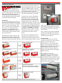
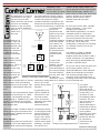
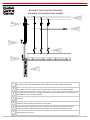
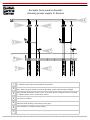
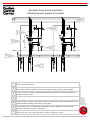
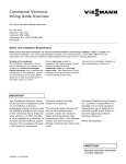
K-W Electronic Service Inc. and Viessmann, partners in heating technology. Controls newsletter, August 2006, Issue 9
Start!
New starts can
come from
various sources.
Take, for
example, this
issue of Vitotalk. The last issue was
sent out in February 2005, over a year
and a half ago! For that very reason,
this issue is dedicated to new starts:
new issue, new heating season, new
articles, new information, and new
controls.
A number of
years ago, you
might recall that
Viessmann introduced a
program called Vitotec. This period
ushered in a whole era of boilers,
controls and other fine hydronic
heating products.
Once again, to make reference to the
theme of this Vitotalk, we must make a
new start with the commercial
Vitotronic controls. But the discomfort
of starting new is minimized by
everybody’s familiarity with residential
Vitotronic 200 and 300 boiler controls.
Let’s start with an overview of what
we had and what we have now.
Fast forward a few years after the
introduction of Vitotec, to present day.
There were four models of boiler
The new Vitotronic “NR2” line of
controls are making themselves known, controls and three models of mixing
Before we continue forward, lets take a project by project. The older Dekamatik valve controls. They all shared the
quick moment to look back to the
controls are all but gone and the time is same menu driven user interface
spring. Viessmann had their anniversary now to start learning about Vitotronic
identical to the now current Vitodens
open house to celebrate their 25 years NR2!
200, WB2 boiler.
in Canada and 20 years in the United
States. This was no easy milestone
Continued on following page
considering the competitive boiler
market, the breadth of the product line Control
Primary Features
at the time and the customers’
Dekamatik E
Outdoor reset
exposure to the name Viessmann.
DHW operation
Operates two mixing valves
It was good to see all those invited to
Communication via 141 2-wire BUS to mixing valve controls
Waterloo for the festivities.
Diagnostics with relay test and sensor checks
So, without further delay, let’s begin!
Dekamatik M1/M2 Outdoor reset
DHW operation
What’s new? Vitotronic NR2 controls,
Communication to system mixing valve controls
Systronik flue gas analyzers, Vitotronic
Diagnostics with relay test and sensor checks
050 HK1Ms, Vitotronic 100 KK10LONs
Up to three boiler communication with Dekamatik M2’s
and Vitosolic solar control, just to name
a few.
KR Boiler Control
Non-outdoor reset
DHW
operation
What’s not new is our desire to provide
BMS
applications
for burner enabling and BMS modulation
as much detailed information that we
Diagnostics
with
relay
test and sensor fault output
can possibly jam into a collection of
Two
stage
burner
control
8.5x11 pieces of paper. So, please
continue reading and if you have any
comments, questions or demands, do
not hesitate to let us know here at
KWE.
Thank you!
KWE editorial staff
HK Mixing Control Outdoor reset
HK1 single mixing valve control
HK2 (in control panels) two mixing valve control
HK4 (in control panels) four mixing valve control
Communication to boiler and other HK controls
Table 1: Overview of Dekamatik boiler controls and mixing valve controls
In This Issue: New Start!•Vitotronic NR2•Hey, are you listening!?•Combustion Theory
VVVVVVVVVVVVVVVVVVVVVVVVVVVVVVVVVVVVVVVVVVVVVVVVVVVVVVVVVVVVVVVVVVVVVVVVVVVVVVVVVVVVVVVVVVVVVVVVVVVVVVVVVVVVVVVVVVVVVVVVVVVVVVVVVVVVVVVVVVVV
K-W Electronic Service Inc. and Viessmann, partners in heating technology. Controls newsletter, August 2006, Issue 9
Page 2
Continued from previous page
both outdoor-reset based controls, as
well as providing control for two mixing
valves and DHW operation. Like the
The changeover of
Dekamatik E, the Vitotronic 300, GW2
commercial controls from the
can communicate to successive
Dekamatik to Vitotronic has taken
place over the past year. This transition Vitotronic HK mixing valve controls via
the LON communication connection.
has been made easier because the
commercial controls are similar to that
The third new control is designed to
of the residential models with respect
integrate up to four Vitotronic 100,
to operation and functionality.
GC1 boiler controls. It provides the
outdoor reset functionality and boiler
Introduction
staging/rotation that is required with
The first control that we are going to
discuss serves double-duty as a stand- multiple boiler systems. As well, it can
alone control or as part of a multi-boiler control up to two supply mixing valves
and is responsible for DHW production
system. It’s name is Vitotronic 100,
in multiple boiler systems. This control
GC1. It can be used as a stand-alone
is available in Standard and Custom
control for use in basic DHW-only
applications. The S version is a wallapplications, simple BMS control or
multiple control applications due to its mounted control and the C version is
incorporated into custom control
communication with a master control,
panels.
the Vitocontrol-S/C.
The second new boiler control is the
Vitotronic 300, GW2. It replaces the
Dekamatik E. They both share a great
deal of the same functionality. They are
Dekamatik-E
Dekamatik-M1/M2
KR
Dekamatik HK2 and HK4
Dekamatik HK1
Above: The pictures above show how the control
panel mounted Vitotronic 333 is flush with the
front of the door. The backside of the door shows
how the Vitotronic 333 front end is mounted
through the door.
also a version of this control called the
Vitocontrol-S, RS/VB2. This control is
designed to work with boilers that use
the KK10 style of control.
The name of the standard control is
Vitocontrol-S, VD2/CT3. This unit is
used with Vitocrossal boilers (CT3) as
Vitocontrol-S/C
well as Vitorond boilers (VD2). There is To open our discussion of the new
Vitotronic controls, let’s start with the
master control, known as the
Vitotronic 300, GW2
Vitocontrol-S/C. It can communicate
with up to four Vitotronic 100, GC1
boilers. This is obviously one more than
the Dekamatiks could. As well, the
master control also has the ability to
Vitocontrol-S, CT3/VD2+
control two mixing valves and operate
Vitotronic 100, GC1
DHW production.
T
T
T
T
T
Vitotronic 100, GC1
The master control comes
fundamentally in two configurations:
Standard and Custom. The standard
unit provides all the functionality of the
control without the options of a custom
control panel. The custom unit is part
of a custom control package.
Continued on following page
Vitotronic 050, HK3S
Mounted in Vitocontrol-C panel as
part of complete system package
Vitotronic 050, HK1M
Table 2: Cross reference between Dekamatik boiler controls and Vitotronic NR2 controls
VVVVVVVVVVVVVVVVVVVVVVVVVVVVVVVVVVVVVVVVVVVVVVVVVVVVVVVVVVVVVVVVVVVVVVVVVVVVVVVVVVVVVVVVVVVVVVVVVVVVVVVVVVVVVVVVVVVVVVVVVVVVVVVVVVVVVVVVVVVV
K-W Electronic Service Inc. and Viessmann, partners in heating technology. Controls newsletter, August 2006, Issue 9
Continued from previous page
on DIN rails inside of the panel. The
pictures on the preceding page shows
these pieces.
In terms of Viessmann
nomenclature, the master
Vitotronic 100, GC1
controls are known as a Vitotronic The Vitotronic 100, GC1 is a boiler
333, MW1 and a Vitotronic 333,
control that provides a
MW1S. Once KWE has worked their
number of various
magic to prepare the controls for the
features depending on
North American market, the
the overall application
name of the
of the control. The
product changes.
control can operate as
This is where the
a stand alone unit,
Standard and Custom
operating strictly on
designations come
set-point. This can
into play.
be a set-point as
determined for space
The standard unit
heating or DHW
looks quite similar to the
control. The control
control that is mounted on
will modulate the burner
the side of the VD2 or CT3
to achieve the desired boiler
boilers. The primary difference
water temperature.
is that while the boiler control
has a harness that runs from the
When the control is used in
control down to the burner, the
conjunction with a Vitocontrol-S, VD2/
Vitocontrol-S does not.
CT3, the DHW function is not part of
the GC1’s operation. As well, if there
The name, Vitocontrol-S, is only one
are specific BMS requirements, refer to
part of the naming structure for the
the manual to know where to connect
control. The second part is in reference the demands/disables.
to the boiler with which it is
communicating with. As an example,
The Vitotronic 100, GC1 has
the most common units are for
the ability to operate 30%
Vitocrossal and Vitorond boilers. This
and 100% boiler
would mean that a standard unit for
protection
multiple boilers is Vitocontrol-S, CT3 or packages for
Vitocontrol-S, VD2.
Vitorond
applications.
As was mentioned earlier, there is also
a Vitocontrol-S, RS/VB2. This control is External control of the
configured to communicate to
Vitotronic 100,
Vitotronic 100, KK10LON boiler
GC1 control
controls. Having a Vitocontrol-S, RS/
can be
VB2 specifically for smaller boilers,
accomplished
means that medium to large residential a number of
applications as well as light commercial ways: local
projects are no longer an issue from a
connection points on
control point of view.
terminal strip inside of junction box, a
0-10VDC input module or a LON card
The Vitocontrol-C is the second
installed into the control. Discussions
product capable of having a Vitotronic regarding alternate configurations of
333 as part of its overall control
the Vitotronic 100, GC1 will be
strategy. The appearance of the
expanded upon at a later date.
Vitotronic 333 that is used in
conjunction with control panels, is such Vitotronic 300, GW2
that the user interface is part of the
This boiler control can best be summed
panel door. All of the main control
up as the evolution of the Dekamatik-E.
parts, such as the power supply, logic While combining all the primary
board and output module, are located
features of the E, it also includes the
Page 3
ability to incorporate the accessories
that are used by the residential
Vitotronic 300, KW2
Boiler Control Installation
Both of the Vitotronic 100 and 300
boiler controls, are installed on the side
of the boiler. In other words, the boiler
controls are NOT installed on the front
or top of the boilers.
Installation of the boiler controls on the
side of the boiler provides the
necessary termination housing to allow
an electrician to terminate their wires.
This includes control power, burner
power as well as all of the outputs of
the control.
In larger boiler applications, having the
boiler control on the side, keeps the
user from having to straddle the burner.
This is particularly useful during startup when the burner tech and the
controls tech are trying to occupy the
same space (those burner guys are
always in the way!)
The controls are mounted on
a mounting bracket that
also houses a DIN
rail with all the
wiring
terminations.
Once the
mounting
bracket is
installed on
the side of the
boiler, the
control is hung
from a couple of
tabs at the top of the
bracket.
The placement of the control is not
specific to one side or another of the
boiler. The design of the junction box
allows the placement of the control to
be determined at the time of
installation. All that is required is
rotating the burner harness/junction box
before fastening it to the backplate.
The next issue of Vitotalk, will cover
wiring of the individual controls as well
as the interconnections with
Vitocontrol-S/C. V
VVVVVVVVVVVVVVVVVVVVVVVVVVVVVVVVVVVVVVVVVVVVVVVVVVVVVVVVVVVVVVVVVVVVVVVVVVVVVVVVVVVVVVVVVVVVVVVVVVVVVVVVVVVVVVVVVVVVVVVVVVVVVVVVVVVVVVVVVVVV
K-W Electronic Service Inc. and Viessmann, partners in heating technology. Controls newsletter, August 2006, Issue 9
In keeping with the theme of new
starts for this issue of Vitotalk, let’s go
way back to the year when fire was
first discovered. By the end of the
first year, everybody had one of
these new fangled fire pits in
front of their caves. Now,
imagine the cavekeeper
grunting with the fire pit
technician, Grog. Now,
Grog grunts to his
apprentice, “Fire burn
rich”. Of course, his apprentice
says, ”Fire burn lean”. Based on
his year of experience, Grog is able to
know when a flame is burning rich or
lean.
throughout our daily lives. For a
moment, think about everything that
combustion does: moves our cars,
buses, planes, provides
heat and electricity as
well as making the raw
materials that go into
virtually EVERYTHING
that we use, touch,
eat or drink.
Page 4
fire was hot, it burned and it worked to
scare away the occasional Sabretoothed tiger or aggressive neighbour.
Today we know lots of things about
fire and its uses. We know that a
properly designed combustion chamber
can give you more fun than you know
what to do with, propelling you from 060MPH in 4.5 seconds. We also know
that CO in high PPM counts can kill in 1
to 3 minutes. Hmmm, sobering
Now, on a smaller
thought. So, aside from avoiding
scale and for the purposes of this
speeding tickets by lifting up on the
discussion, let’s just look at the
aspect that people depend on everyday: accelerator pedal, how do we prevent
excessive CO during combustion?
heating their homes. Generally, a
second thought about heating is never
One of the first
given unless they
ways to prevent
have no heat.
CO is to have a
That’s when it
healthy respect for
hit’s the fan.
how badly things
Nevermind the
can go wrong
fact they were just
when a burner or
talking to their
combustion device
buddies and
is not set up
bragging that their
properly. The first
heating appliance
hurdle
to
get
past
this
is to be able to
is so good, they don’t need to have it
measure CO.
serviced. Yeah, right.
The reason why they were called to
have a look at the pit was there was a
complaint that the fire was not as hot
as it was a few weeks previous. Grog
pulls out his trusty fire poker from his
mammoth skin tool pouch to inspect
the fire further. Little did Grog and his
apprentice know, but the cavekeeper
neglected to inform Grog they were
feeding the fire with wet wood. The
extra moisture was causing all sorts of
smoke and resulting in complaints from
the neighbouring caves. There was
In the real world, it is very important to
only one fix for this, build a new fire
have the equipment that is such an
with good, dry wood. Grog and his
integral part in our lives looked at and
apprentice collected
maintained. Yes, there are
their pelt payment and
those that say, “I bought
carried onto their next
the best!” You may think
call.
that means it doesn’t have
to be serviced, but, alas, IT
Fast forward to modern
DOES!
day and consider all the
tried and true methods
So, back to the good ole’
of setting up a burner,
days of yore when using a
shaker bottles, flue gas
fire poker and an eye were
analyzers or even a
the tools of choice. Don’t
smoke test. Now, how
you think that Grog, and
many service
maybe to a lesser extent
technicians have you
his apprentice, would have
met that can set up a
liked to know if they were
burner with their trusty eye. “Oh, yeah. making CO. Maybe they would like to
Nice and blue, that is just perfect,” or
know if their NOx levels were right or if
“Nice and orange, that’s the way to
the fire could have been tweaked a
go!” Ring a bell?
little to get a little more heat or
efficiency? Bet that they would!
Combustion is a science unto itself, but
we do not give it a second thought
Back in those days, all they knew was
Looking at the CO2 graph on this page,
do you really think that by eyeballing a
flame you can distinguish between a
CO2 reading of 11 or 12%? This is
where a flue gas analyzer is the only
way to know for sure how the
combustion is functioning.
Adjustment of combustion comes down
to two basic ingredients: Air and Fuel.
When the ingredients are together in
the correct amount, its all good. But
when the amounts are off, hello
heartburn!
There are times when adjusting the
amount of air is not possible. As an
example: an atmospheric boiler does
not allow for an air adjustment. Do you
know why? Because it’s
atmospheric?...phew, that was easy.
An atmospheric burner only uses the air
that is available to it.
Continued on page 7
VVVVVVVVVVVVVVVVVVVVVVVVVVVVVVVVVVVVVVVVVVVVVVVVVVVVVVVVVVVVVVVVVVVVVVVVVVVVVVVVVVVVVVVVVVVVVVVVVVVVVVVVVVVVVVVVVVVVVVVVVVVVVVVVVVVVVVVVVVVV
K-W Electronic Service Inc. and Viessmann, partners in heating technology. Controls newsletter, August 2006, Issue 9
Page 5
analyze These!
filter trap as part of the sampling hose.
The Maxilyzer condensate and filter
traps are located on the upper cover of
the analyzer case.
Another feature of the Eurolyzer,
Multilyzer and Maxilyzer is that the CO
sensor is H2 compensated. What this
means is that during the combustion
process, Hydrogen (H2) may be
While this may seem like a minor point, present in the products of combustion.
the ability to quickly see how much
The presence of H2 in the combustion
condensate is being accumulated, as
gases can provide an erroneous high
well as knowing when it is to be
CO analyzer reading.
drained, can provide very useful. This
ensures that you are not forced to
In keeping with CO, the Maxilyzer and
empty the trap at an important time
Multilyzer have built-in CO bypass
We currently carry four
during the calibration of the burner.
pumps. In case the unit is exposed to a
models that Systronik makes. The
higher than allowed CO reading, the
names of these units are Prolyzer,
A “Coalescence” filter provides
pump will automatically come on and
Eurolyzer, Multilyzer and Maxilyzer.
excellent filtration by scrubbing the flue purge the unit of the excessive CO.
gas sample and virtually eliminating any This pump can also be turned on via
The four units provide excellent
the key pad by the user should the unit
coverage over most budgets and overall condensate. This provides for a much
more accurate reading of the flue gas
need to be purged before the limit is
usage. All the analyzers are well built
properties by the analyzer sensors.
reached.
and share a number of the same parts
across the board. This allows for a
The CO protection mode of the
certain amount of flexibility for
Prolyzer and Eurolyzer units
those companies that utilize the
cause the main pump to shut
various Systronik models.
down at limit. A natural purging
of the unit will have to occur
The Prolyzer, Eurolyzer and
The battery or power supply part of the before the unit is able to measure
Multilyzer all have holsters which
analyzer is something that everybody
properly.
protect the unit and allow them to
should look at and consider before
attach on the side of the boiler via
purchase. The two sister units Prolyzer, The Eurolyzer, Multilyzer and Maxilyzer
magnets. This placement allows for
and Eurolyzer, use AA batteries for
units are approved by TÜV SÜD By
easy access during burner calibration.
their operation. In a pinch, it is also
RgG 190, By RgG 219 and By RgG
possible to use a 9VDC battery to
220 respectively, as well as DIN EN
The Maxilyzer unit is housed in a
50379 and CE approval bodies. Check
rugged waterproof case that is ideal for power the unit in case they should go
dead. There is also a power adapter to to see if the other units that you are
lab environments or work in the field.
allow you to operate the units if the
looking at meet the same criteria to
achieve these approvals.
Printing out the recorded measurements batteries were not replaced in time.
for your customer is also very
The Multilyzer and Maxilyzer units use As part of the complete analyzer kit, a
convenient. The Maxilyzer is the only
internal nickel metal hydride battery
basic carrying case is supplied to house
unit out of the family of four that
packs. This allows the units a long
all of the analyzer accessories. If you
provides and on-board impact printer.
operation times as well as the
require a more robust case, there are
The remaining units all use an HP
capability to power/recharge the unit
other options available such as metal or
infrared thermal printer.
during operation. An internal smarteven a “Pelican” poly-style case.
Knowing what can happen on a flight
Those of you that have researched the charge system prevents the batteries
from being overcharged.
from one side of the
various manufacturers of flue gas
continent to the other
analyzers will know that Systronik
provides us with the
analyzers provide a very convenient and Some manufacturers of flue gas
hands-on knowledge
accessible spot for the condensate trap analyzers use lead acid batteries in
their units. Generally, these types of
of care that these
and filter assembly. The Systronik
kinds of devices can
product uses a condensate trap that is batteries do not like deep cycle
operation as well as being putting
receive...or not.
very easily monitored for condensate
away discharged. The can also be very
levels. All of the units, except for the
expensive to replace when necessary.
Maxilyzer, have the condensate and
For the past couple of
years, K-W Electronic
Service Inc., has
developed a close
relationship with a
manufacturer of flue gas
analyzers from
Germany. The name of
this company is
Systronik.
Continued on page 6
VVVVVVVVVVVVVVVVVVVVVVVVVVVVVVVVVVVVVVVVVVVVVVVVVVVVVVVVVVVVVVVVVVVVVVVVVVVVVVVVVVVVVVVVVVVVVVVVVVVVVVVVVVVVVVVVVVVVVVVVVVVVVVVVVVVVVVVVVVVV
K-W Electronic Service Inc. and Viessmann, partners in heating technology. Controls newsletter, August 2006, Issue 9
Page 6
Eurolyzer
Prolyzer
Light and Portable
CO and O2 gas measurement
Powered by AA batteries
AC power supply
0-2000PPM CO
External IR printer option
Draft measurement
Calculation of Co2, Excess air,
North American Combustion
Efficiency and Flue Gas Losses
Light and Portable
CO and O2 gas measurement
Powered by AA batteries
AC power supply
0-4000PPM CO
H2 Compensation
External IR printer option
Draft measurement
Ambient CO measurement program
Calculation of Co2, Excess air, North
American Combustion Efficiency and
Flue Gas Losses
Maxilyzer
Multilyzer
Light and Portable
CO and O2 and NO gas
measurement
Optional 4th sensor
NiMH battery pack
AC power supply
0-4000PPM CO
External IR printer option
Draft measurement
RS232 Interface
Calculation of Co2, Excess air,
North American Combustion
Efficiency, Flue Gas Losses and NOx
Rugged enclosure for harsh
environments
CO and O2 and NO gas
measurement
Optional 4th sensor
NiMH battery pack and AC power
supply
0-4000PPM CO
Integrated impact printer
Draft measurement
RS232 Interface
Calculation of Co2, Excess air,
North American Combustion
Efficiency, Flue Gas Losses and NOx
Continued from previous page
Analyzers purchased through KWE or
our partners are all serviced at our
facilities in Waterloo, Ontario, Canada.
Turn around time for cleaning and
calibrations is generally within a week
of receiving the unit.
As far as inventory of product, all
efforts are taken to ensure that
analyzers are available at a moments
notice. If, however, something special
is required, it generally takes a couple
of weeks from the manufacturer.
Those of you who are considering an
through pressure meters, take moment
to talk to us. For more information
regarding analyzers and combustion
check out the K-W Electronic Service
Inc., web site at
www.kwelectronicservice.com or go
In the next issue of Vitotalk, we will go directly to:
www.kwelectronicservice.com/
through the bits and pieces that make
a Systronik analyzer what it is. As well, kweweb/CombTheory.htm
or have a look at:
a review of what is required to take
www.kwelectronicservice.com/
measurements with the analyzers.
kweweb/Analyzers.htm
Oh, by the way, Systronik also makes Look in the next issue of Vitotalk for
the new Multilyzer-NG and a detailed
a great pressure meter. For those of
review of features. V
you who are continuously running
analyzer, consider trying a Systronik on
for size. We have a number of units
that are able to travel by themselves to
exotic locations, from Nantucket to
Nanaimo.
VVVVVVVVVVVVVVVVVVVVVVVVVVVVVVVVVVVVVVVVVVVVVVVVVVVVVVVVVVVVVVVVVVVVVVVVVVVVVVVVVVVVVVVVVVVVVVVVVVVVVVVVVVVVVVVVVVVVVVVVVVVVVVVVVVVVVVVVVVVV
K-W Electronic Service Inc. and Viessmann, partners in heating technology. Controls newsletter, August 2006, Issue 9
Continued from page 4
technician with all the necessary
flexibility to ensure proper combustion.
Adjustments made during start-up with
There is this funny
the fuel and air are immediately
thing that happens
viewable with the combustion analyzer.
when you go up into higher
It is important for the start-up
elevation areas; there is less mass
technician to realize that the fuel/air
weight of air. At this point, you have to mix is a fine balance. If the analyzer
de-rate the appliance based on
shows that the combustion is a little
established code guidelines and
rich/lean, this maybe due to not enough
practices.
air/fuel or too much air/fuel. These
adjustments are never black and white,
A power burner, by its very nature of
but rather various shades of grey.
mechanically moving the air, allows the
start-up technician to compensate for
Start-up technicians with experience on
elevation changes. Along with air
their side, know that there are lots of
adjustments, incoming gas supply is
tricks when dialing in a burner. There
also adjustable. The combination of
are generally gross adjustments which
both air and fuel provide the start-up
are initially made and any tweaking is
Soap
Box
Page 7
accomplished with fine tuning
adjustments.
In future issues of Vitotalk, the topic of
combustion will be further explored.
More detailed information will be
reviewed to provide a better
understanding of combustion.
A closer look at what happens when
the sample enters the wand of a flue
gas analyzer will be discussed. V
If you have any comments or questions
regarding this topic, please let us know.
[email protected]
Tel: 1-519-747-5042
Fax: 1-519-747-4448
made to work for itself. Think of it as
another employee, but one that isn’t
going to embarrass you and make a
fool out of themselves at the
Christmas/Hanukkah/Kwanzaa work
party. Develop a per-use charge and
factor it into your regular services.
freezing temperatures. Any of the
condensate that could possibly remain
would freeze and cause potential
damage.
Vitotalk 3: June 2002
Now! That’s a Switch—Switches
and Relays
Vitodens (first article) External demand
Multimeter Basics
Vitotalk 6: May 2004
Summer is in the Air!
Phundamentally Fhysics—GFCI’s
Learning LON—first LON discussion
Diagnostic Do’s and Don'ts
Cascade Control—Part Deux
Cleaning and calibration of the analyzer
is performed by the people that it was
Having the tools
purchased from. Like any tool that
necessary to perform any Once the analyzer is purchased, it must provides you with readings or
task is paramount to
information, it needs to be calibrated.
be understood that it has to be
being professional and
Did you know that there are companies
maintained on a day-in and day-out
responsible. Various
that calibrate your voltmeters or multibasis on top of being cleaned and
different trades spend
meters?
calibrated. Daily maintenance ensures
lots of money on their
that condensate does not access the
tools and this trade is no unit. The hoses should be drained
Make sure the time is taken to ensure
different. In the case of flue gas completely and any dirty filters
your test equipment is up to the task
analyzers, you can spend a little money discarded in favour of new ones. For
for day-in and day-out usage.
or a lot of money for one unit.
Remember that you generally never
service technicians that work out of
Whatever manufacturer or how much
their trucks, do not keep the analyzers regret spending more money on
you have paid for it, the unit has to be in the trucks if there is the possibility of something you may use everyday. V
Looking Back
Until now, there have been 8 issues of
Vitotalk. Many topics covered, but lets
look back to see what have been
discussed so far.
Vitotalk 1: January 2002
Switching Module V
A Little Electrical Theory
Vitotronic Room Influence Addressing
Vitotalk 2: May 2002
Leading Word on Lag Modules
Slippery Slope to WWSD Point
Electrical Theory: 41 Plug
Vitotalk 4: February 2003
Most Referenced Issue!!!
In The Mix: Vitodens & Mix ‘N’ Valves
Addition of communication board
Wiring of 141 Communications
Whole lot more!!!
Vitotalk 5: August 2003
Tips ‘N’ Tricks
Phundamentally Fhysics—Transformers
Heating curves Viessmann vs Cascade
LOTS of Cascade Control Information
Vitotalk 7: November 2004
All Dried Up—Making of a Dry Contact
Cascade Control—Part Deux Revisited
Vitocontrol-S—Not So Extreme
Makeover
Vitotalk 8: February 2005
Communications Issue—GREAT
information...to much reading 19
pages!. Do yourself a favour and reread!!! Great pictures!
VVVVVVVVVVVVVVVVVVVVVVVVVVVVVVVVVVVVVVVVVVVVVVVVVVVVVVVVVVVVVVVVVVVVVVVVVVVVVVVVVVVVVVVVVVVVVVVVVVVVVVVVVVVVVVVVVVVVVVVVVVVVVVVVVVVVVVVVVVVV
K-W Electronic Service Inc. and Viessmann, partners in heating technology. Controls newsletter, August 2006, Issue 9
Hey! Are You Listening!?
There is a fundamental
truth about
communication
technologies, whether it
be now or a hundred years ago: No
matter the medium, the message has
the possibility of being misunderstood.
At no time in history has this been so
apparent than right now, during the
communication and information age.
and now I can’t get them to
communicate.” Now, hold on for a
moment, did you honestly believe it
was that easy? Put tab A in slot B and
violà, communications.
It has only been during last decade or
so that the possibility of universal
communications between different
manufacturers has even been
addressed. Years of proprietary control
protocols from the three main industry
How many times have
leaders is changing. The writing was on
you pulled up to your
the wall for this kind of strategy. As
local coffee shop
drive-thru window to more and more device manufacturers
be greeted by a voice started accepting an open
communication protocol platform, the
over the crackly
industry was forced to change.
speaker, “Hello, how
Hopefully, this will provide a level
m% $ %^&* I :) h(:) (*^&^#% me
playing field for small to large control
&^%^&**. This is a fine example of
providers.
how one of the most simplistic
communication moments, and yet the
What is and isn’t
outcome can ruin your whole day.
communication? Is
there really a
The objective of a communications
difference
exchange has to be determined, or at
between communicating
the very least expected, before the
information or communication starts. It and demanding/
commanding? There are
must be clear and concise. The
exchange has to be understood by both those who think that they
parties to ensure a correct and desired are the same...well they’re not.
outcome.
Communication is the exchange of data
and information from a sender to a
Again for a moment, return to the
same drive-thru at your favorite coffee receiver. There is a data exchange that
takes place between those devices that
shop. Seems like you have been
waiting for hours, doesn’t it? Instead of are interconnected with one another.
Quite often, reference is made to a
a coffee and a muffin, order a burger
communications protocol that basically
and fries. In a split second you have
refers to the language that is
altered the anticipated
used between the sender and
communication exchange
the receiver. As an example,
between you and that underif you were trying provide a
paid voice at the other end.
tourist with directions,
At this point, the answer you
to...let’s say a coffee shop,
will receive is anybody’s
but they didn’t understand
guess. It is this aspect that is
English, the likelihood of
the very same with respect
complete understanding would be very
to interconnecting control devices.
slim. There are also those times when
There is an ever increasing demand for even speaking English, words or
electronic devices to communicate with phrases may be used, but not
one another. Time and time again, you universally understood.
hear the complaint, “Yeah, I bought
this orange boiler and this blue control How does demanding or commanding
Page 8
Wie ist
das Wetter?
differ? Generally a demand
or command takes the form
of a yes/no, on/off or open/
closed operation. The
output of a control or device is a
function of the input. If a specific input
is demanded, a specific output occurs.
The fundamentals have to be
understood and applied correctly when
talking about interconnections between
controls. Here are some examples of
both communication and demanding/
commanding and certain aspects of
each method.
Communication or Communicating:
1. Specific protocol
2. Specific media
3. Control gateway
4. Large amounts of data exchanged
between controls
Demanding or Commanding:
1. Burner external enable
2. Burner external disable
3. Burner high fire demand
4. Burner call for heat
5. Demand for DHW
Here are a couple of applied examples.
Check the correct boxes and look to
the back page for the correct answer:
TT connection to KK10/K10:
Communication
Demand/Command
BMS connections to 143/146 plugs:
Communication
Demand/Command
Dekamatik-M1 to Dekamatik M2/HK:
Communication
Demand/Command
Vitocontrol-S, WB2 to Vitodens boilers
Communication
Demand/Command
Interconnections from Vitocontrol-S/C:
Communication
Demand/Command
V
VVVVVVVVVVVVVVVVVVVVVVVVVVVVVVVVVVVVVVVVVVVVVVVVVVVVVVVVVVVVVVVVVVVVVVVVVVVVVVVVVVVVVVVVVVVVVVVVVVVVVVVVVVVVVVVVVVVVVVVVVVVVVVVVVVVVVVVVVVVV
K-W Electronic Service Inc. and Viessmann, partners in heating technology. Controls newsletter, August 2006, Issue 9
Page 9
Control Corner
Custom
Depending on the
120VAC Power supply module. In a
system, you may or
typical application of this control panel
may not have to include module would supply 120VAC to a
this functionality into
boiler control or some other device that
The application of a custom
the panel. However, having a control
requires 120VAC for its operation.
control panel to any job is
panel provide local control/distribution
Note the On/Off switch, status
like the icing on a cake.
of boiler control/burner voltage,
indicator lamp and the output
When done well, the custom primarily eliminates hunting down the
terminals.
control is an invaluable
elusive job site electrician during times
addition to any new boiler
of start-up and servicing. It should also As we move from the basic 120VAC
room or retrofit installation.
be noted that as
output of Drawing 1, to the more
However, it
part of the
complex power supply for
Power Supply
seems to be
components that
460/575VAC applications, we see an
the most
make up the power increased number of components
supply portion of
within the power supply module. Note
the panel, the
the circuit protection with the fuse/
misunderstood part of
necessary breakers/ breakers. A disconnect switch controls
Wire interconnections
the system. There can
fuses are included
On and Off, via its three pole
be lots of answers for
in the panel. The
configuration. A 4th pole for switching
Fuse/Breaker
this, but hopefully, this
only
aspect
that
is
of a 120VAC control circuit is also
Protection
series of articles will
generally required
incorporated.
address the unknowns
by the electrician is
to take care of any
a feed from the
The inability to create a 120VAC
unanswered questions.
main disconnect
circuit from 460/575VAC power
Switch
panel.
supplies means that we have to add a
Where to start? First
control transformer. This transformer
of all, a custom control
As part of the
takes the incoming 460/575VAC and
panel is called a
control panel
provides a 120VAC output.
Vitocontrol-C. The C is
features, you may
Status
Output
a designation for
Indicator
also incorporate
As you can see by looking at these two
Termination
L
G
N
Lamp
Custom and the word
visual identification power supply options, they are
Vitocontrol is
of incoming voltage. somewhat different in their individual
120VAC
Power Supply
representative for the
In some instances, details the functionality is the same.
for Burner/
Control
family of controls. As
you may even want The incoming voltage supply is run
most of you already
an alarm for
through a circuit protection device, a
Drawing 1: Power Supply 120VAC Output
know, there are
notification if there switching device and is then outputted
Vitocontrol-S controls that are “off-the- should be a voltage drop-out or a blown to the connected load.
shelf” controls which provide basic
fuse for one of the
Power Supply
control functions for the system. This
phases during regular
In a typical
is where a C differentiates itself from
operation.
application, when
an S.
sizing the overall
A great deal of the
power supply for the
Wire interconnections
Quite often, the most frequently asked options available on
control panel, it is
Fuse/Breaker
Fuse/Breaker
question of a Vitocontrol-C is, “What
Vitocontrol-C’s are
necessary to know
Protection
Protection
can it do?” The response that gets
the result of past
the amperage load of
heads spinning is, “Whatever you want users’ and owners’
the panel. The only
it to do”. The features of the panels
experience with either
way to do this is to
really has more to do with imagination Multimatik or
add the various
than anything else.
Vitocontrol panels.
output amperages of
the devices as well as
4 Pole of Disconnect
Switch/
Switch
Disconnect
There are a number of baseline features The drawings shown
of each burner blower
which provide great convenience and
on this page provide a
motor together.
Output
service-friendly capability that should
pictorial overview of
Obviously, this would
Terminations
not be overlooked.
Status
the bits and pieces
require knowing all
Indicator
Lamp
that go into a power
the devices that will
120VAC
460/575VAC,
Power Supplies
supply ‘module’ in a
be controlled or
Control Power
3PH Power
Supply
Supply for
A good starting point for Vitocontrol-C custom control panel.
Burner/Control
connected to the
functionality is to first address power
Drawing 1, provides
Vitocontrol C.
Drawing 2: Power Supply 460/575VAC
supplies—both incoming and outgoing. an overview of a
AC
Off On
AC
460/
575
VAC
120
VAC
th
Off On
L1
Step down
Transformer
3PH to
120VAC
L2 L3
L1
G
N
Continued on following page
VVVVVVVVVVVVVVVVVVVVVVVVVVVVVVVVVVVVVVVVVVVVVVVVVVVVVVVVVVVVVVVVVVVVVVVVVVVVVVVVVVVVVVVVVVVVVVVVVVVVVVVVVVVVVVVVVVVVVVVVVVVVVVVVVVVVVVVVVVVV
K-W Electronic Service Inc. and Viessmann, partners in heating technology. Controls newsletter, August 2006, Issue 9
Continued from previous page
Once this current load
is calculated, the
electrician or whoever
is responsible for the
main electrical panels
can install the appropriate breaker/
fuses for your Vitocontrol-C panel.
Pump Control
The control of various pumps within a
system is another invaluable feature of
the Vitocontrol-C. Whether the job is a
new installation or a retrofit, the
control panel is able to provide the
control necessary to operate the
system pumps.
Page 10
be determined prior to commencing
Some examples are:
with the control panel design. The
• Boiler supply pump
biggest question of all is how the
• Boiler shunt pump
pumps are to be controlled. This aspect
• DHW pump
generally depends on the overall
• DHW recirculation pump
operation of the devices. When the
pumps are used primarily for space
• Space heating pump with M/V
heating, a signal is provided by the
control
outdoor reset controller to turn the
• Space heating pump with TT
pumps on in the fall and off in the
control
spring.
• Pool pump
There may be parts of the system that • Spa pump
do not require constant circulation. This Just to name a few…
is where demand control of pumps
comes into play. Pumps that are
controlled by devices such as set point
controls or room thermostats, are
Quite often, in older systems, a visit is outputs to be cycled on and off. The
primary consideration of this kind of
required to turn off the pumps for the
summer season. This will also lead to a control is that for any controls external
to the panel, a demand signal will be
visit in the fall to turn on the pumps
once again. However, a custom control required to know when to start and
stop the pump.
panel can provide warm weather shut
down which allows the service person
There are a number of various pump
to address more important matters.
outputs that can be used. These will
vary, depending on the complexity of
Similar to the various power supply
options, there are a number of aspects the systems.
of pump control that are necessary to
Power Supply
Power Supply
AC
A number of options can be used with
the various selections of pumps,
regardless if the pump is for a boiler or
a towel rad. Some of them include
rotation for multiple pumps, dual head
control as well as VFD control. When
addressing the option list, there may
also be aspects of the system that have
to be addressed as well. If you are
installing back up pumps in case of a
pump failure, it is imperative that the
necessary isolation valves are installed
to allow for servicing of the defective
pump. If the intent is to have an
automatic pump back-up, then you may
need flow switches installed. If this is
the case, then the output of the flow
switch will need to be run back to the
control panel.
AC
Wire interconnections
Control
Signal
Wire interconnections
Fuse/Breaker
Protection
Off
Auto On
I>
I>
I>
Auto/Off/On
Switch with
Lamp
Switching
device such as
relay or
contactor
R
L
L
L
Overload
Protection with
Failure
Indication
Output Lamp
G
Output
Termination
Control
Signal
Fuse/Breaker
Protection
R
Auto/Off/On
Switch with
Lamp
L
Output
Device
Switching
device such as
relay or
contactor
Off
Auto On
Output
Device
L
G
Output
Termination
Depending on how the options are
configured, this will affect the overall
operation of the panel as well as the
total load calculation. In a case where
standby or back-up pumps are capable
of operating at the same time, the
panel power supply has to be sized for
the total current draw of all the pumps.
If a mechanical/electrical interlock is
used, then the panel can be sized for
only the pumps that are capable of
running.
When providing information for pump
control, it is necessary to supply both
the voltage and current requirements of
the pump. It is very important that HP
figures are not used to determine
current demands. Information regarding
current loads can vary greatly in
respect to similar sized HP figures. One
manufacturer may quote a 5HP pump
at 2FLA whereas another may specify
7FLA.
Continued on following page
VVVVVVVVVVVVVVVVVVVVVVVVVVVVVVVVVVVVVVVVVVVVVVVVVVVVVVVVVVVVVVVVVVVVVVVVVVVVVVVVVVVVVVVVVVVVVVVVVVVVVVVVVVVVVVVVVVVVVVVVVVVVVVVVVVVVVVVVVVVV
K-W Electronic Service Inc. and Viessmann, partners in heating technology. Controls newsletter, August 2006, Issue 9
Continued from previous page
The differences in
amperage ratings
between the pumps
may add up to
hundreds of dollars
worth of relays, contactors or
overloads.
take before a C is created. What
happens once the approval drawings
are “Okayed”? We will go through the
various steps taken to bring a panel to
life. As well, you may be asking
yourself, “What happens once it leaves
your shop doors”. Well, that is an
excellent question too.
The installation of a custom control
The photographs on this page show
the sections contained within a typical panel is a frequently asked question:
control panel. The photographs also
• How does it get mounted to the
relate to the module drawings included
wall?
in this edition of Vitotalk. Following the • Can it be suspended?
pictures, samples of a panel schematic
• Who wires it?
have also been included. By including
• What kind of wire is used?
the module, picture and schematics,
• How heavy is it?
you will be able to see how they all
interrelate with one another.
•
•
•
•
•
Page 11
What happens when replacement
parts are needed?
What is the panel rated for?
How do you change a bulb?
How do you change a switch?
How is the panel diagnosed?
These are only a sampling of the
questions that we receive.
So, look to future issues of Vitotalk for
all of these questions to be answered.
In the meantime, should you have any
questions, please contact us.
Upcoming editions of Vitotalk will
expand further on the various aspects
of Vitocontrol-C panels. This includes
mixing valve controls, pool and spa
controls, snow melting controls, DHW
controls and some other unique
applications.
The design of the control panel is only
one piece of the puzzle when creating
a Vitocontrol-C. Future issues of
Vitotalk will review the various steps
Picture 1: Distribution terminals
Picture 6: Switches
Picture 5: Contactors
Picture 2: Main Fuses
Picture 4: Overloads
Picture 3: Fuses
VVVVVVVVVVVVVVVVVVVVVVVVVVVVVVVVVVVVVVVVVVVVVVVVVVVVVVVVVVVVVVVVVVVVVVVVVVVVVVVVVVVVVVVVVVVVVVVVVVVVVVVVVVVVVVVVVVVVVVVVVVVVVVVVVVVVVVVVVVVV
K-W Electronic Service Inc. and Viessmann, partners in heating technology. Controls newsletter, August 2006, Issue 9
Page 12
Excerpts from panel schematic
showing incoming power supply
5
4
6
3
7
2
1
1
Incoming power supply sized for entire load of panel with all devices connected and
functioning. Note 3 phase 208VAC. Electrician must provide fuseable disconnect.
2
Section of DIN rail inside of panel where all field connections are made. Depending on
panel, there may be a number of sections providing various inputs/outputs/voltages.
3
Main panel On/Off disconnect. Usually mounted on side of panel. Note the switching of all
three phases of the incoming 208VAC.
4
Main fuses provide protection for entire panel. Each circuit is also fused for short circuit
protection.
5
On-going supply wiring to other areas within the control panel. Entire schematic has to be
referenced when looking to see where power goes.
6
Voltage take-offs within panel provide voltage to panel devices & accessories. Note
numbering scheme referencing pages and sections of associated schematic pages.
7
Status indicators for all three legs of incoming power supply. Note that each indicator is
protected by its own fuse.
VVVVVVVVVVVVVVVVVVVVVVVVVVVVVVVVVVVVVVVVVVVVVVVVVVVVVVVVVVVVVVVVVVVVVVVVVVVVVVVVVVVVVVVVVVVVVVVVVVVVVVVVVVVVVVVVVVVVVVVVVVVVVVVVVVVVVVVVVVVV
K-W Electronic Service Inc. and Viessmann, partners in heating technology. Controls newsletter, August 2006, Issue 9
Page 13
Excerpts from panel schematic
showing power supply to burners
5
4
6
3
7
2
1
1
1
Power supply output to burner and control. Note that the burner has no Neutral wire but
the 120VAC output has Line and Neutral connections.
2
Section of DIN rail inside of panel where all field connections are made. Depending on
panel, there may be a number of sections providing various inputs/outputs/voltages.
3
Panel mounted disconnect switch to turn off 3 phase burner voltage as well as switching
the 120VAC power source to the boiler control.
4
Circuit breaker to provide overload protection. Switches all three phases off when trips.
Only removes 3 Phase.
5
On-going supply wiring to other areas within the control panel. Entire schematic has to be
referenced when looking to see where power goes.
6
Circuit breaker for 120VAC control voltage.
7
Power ON status of boiler control power supply.
VVVVVVVVVVVVVVVVVVVVVVVVVVVVVVVVVVVVVVVVVVVVVVVVVVVVVVVVVVVVVVVVVVVVVVVVVVVVVVVVVVVVVVVVVVVVVVVVVVVVVVVVVVVVVVVVVVVVVVVVVVVVVVVVVVVVVVVVVVVV
K-W Electronic Service Inc. and Viessmann, partners in heating technology. Controls newsletter, August 2006, Issue 9
Page 14
Excerpts from panel schematic
showing power supply for pumps
5
6
4
3
7
3
1
Output 208VAC for 3 phase pump control. All components suitable for the 3.6A draw
that the pump is rated for.
2
Section of DIN rail inside of panel where all field connections are made. Depending on
panel, there may be a number of sections providing various inputs/outputs/voltages.
3
Current overload, contactor, ON status switching and auxiliary switch blocks make up a
complete 3 phase output.
4
Pump fuses provide protection for specific output.
5
On-going supply wiring to other areas within the control panel. Entire schematic has to be
referenced when looking to see where power goes.
6
Control panel door switch operates Auto/Off/On function. Bypass the call from boiler
control for operation of pump in ON mode.
7
Fault indicator mounted on panel door to indicate that the motor overload has tripped and
needs to be reset, once the pump and/or wiring is checked for faults.
Answers from Communication/Demand test
Demand/Command
Demand/Command
Communication
Communication
Both
1
VVVVVVVVVVVVVVVVVVVVVVVVVVVVVVVVVVVVVVVVVVVVVVVVVVVVVVVVVVVVVVVVVVVVVVVVVVVVVVVVVVVVVVVVVVVVVVVVVVVVVVVVVVVVVVVVVVVVVVVVVVVVVVVVVVVVVVVVVVVV