1
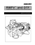
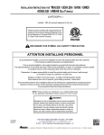
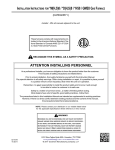
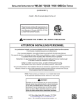
®
AGP-2000 Series
Ticket Dispenser
INSTALLATION / OPERATIONS MANUAL
Amano Cincinnati, Inc. reserves the right to make equipment changes and improvements
which may not be reflected in this document. Portions of this document may have been
updated to include the latest hardware or firmware version, if applicable.
We recommend that this document be read in its entirety before any attempt is made to operate the equipment.
PROPRIETARY NOTICE
This document contains proprietary information and such information may not be reproduced
in whole or in part without written permission from Amano Cincinnati, Inc., 140 Harrison
Avenue, Roseland, New Jersey, 07068
TABLE OF CONTENTS
Chapter 1: INTRODUCTION . . . . . . . . . . . . . . . . . . . . . . . . . . . . . . . . . . . . . . . . . 1-1
Chapter 2: SPECIFICATIONS . . . . . . . . . . . . . . . . . . . . . . . . . . . . . . . . . . . . . . . . 2-1
Pedestal . . . . . . . . . . .
Electrical . . . . . . . . . .
Standard Features . . .
Cabinet Design . . . . . .
Upper Mechanism
Lower Mechanism
.
.
.
.
.
.
.
.
.
.
.
.
.
.
.
.
.
.
.
.
.
.
.
.
.
.
.
.
.
.
.
.
.
.
.
.
.
.
.
.
.
.
.
.
.
.
.
.
.
.
.
.
.
.
.
.
.
.
.
.
.
.
.
.
.
.
.
.
.
.
.
.
.
.
.
.
.
.
.
.
.
.
.
.
.
.
.
.
.
.
.
.
.
.
.
.
.
.
.
.
.
.
.
.
.
.
.
.
.
.
.
.
.
.
.
.
.
.
.
.
.
.
.
.
.
.
.
.
.
.
.
.
.
.
.
.
.
.
.
.
.
.
.
.
.
.
.
.
.
.
.
.
.
.
.
.
.
.
.
.
.
.
.
.
.
.
.
.
.
.
.
.
.
.
.
.
.
.
.
.
.
.
.
.
.
.
.
.
.
.
.
.
.
.
.
.
.
.
.
.
.
.
.
.
.
.
.
.
.
.
.
.
.
.
.
.
.
.
.
.
.
.
.
.
.
.
.
.
.
.
.
.
.
.
.
.
.
.
.
.
.
.
.
.
.
.
.
.
.
.
.
.
.
.
.
.
.
.
.
.
.
.
.
.
.
.
.
.
.
.
.
.
.
.
.
.
.
.
.
.
.
.
. . . . . . . . . 2-1
. . . . . . . . . 2-1
. . . . . . . . . 2-2
. . . . . . . . . 2-4
. . . . . . . . . 2-4
. . . . . . . . . 2-5
Chapter 3: INSTALLATION . . . . . . . . . . . . . . . . . . . . . . . . . . . . . . . . . . . . . . . . . . 3-1
Prepare the Unit . . . . . . . . . . . . . . . . . . . . . . . . . . . . . . . . . . . . . . . . . . . . . . . . . . . . . . . . . . . . . 3-1
Unpack the Unit . . . . . . . . . . . . . . . . . . . . . . . . . . . . . . . . . . . . . . . . . . . . . . . . . . . . . . . . . 3-1
Remove the Skid . . . . . . . . . . . . . . . . . . . . . . . . . . . . . . . . . . . . . . . . . . . . . . . . . . . . . . . . . 3-1
Mounting the AGP-2000 . . . . . . . . . . . . . . . . . . . . . . . . . . . . . . . . . . . . . . . . . . . . . . . . . . . . . . .3-2
Electrical Connections . . . . . . . . . . . . . . . . . . . . . . . . . . . . . . . . . . . . . . . . . . . . . . . . . . . . . . . . 3-3
Main Power . . . . . . . . . . . . . . . . . . . . . . . . . . . . . . . . . . . . . . . . . . . . . . . . . . . . . . . . . . . . . 3-3
Connection Locations . . . . . . . . . . . . . . . . . . . . . . . . . . . . . . . . . . . . . . . . . . . . . . . . . . . . . . 3-4
Communications Wiring . . . . . . . . . . . . . . . . . . . . . . . . . . . . . . . . . . . . . . . . . . . . . . . . . . . . 3-5
Termination Resistors . . . . . . . . . . . . . . . . . . . . . . . . . . . . . . . . . . . . . . . . . . . . . . . . . . . 3-5
Field Connections (24 VDC) . . . . . . . . . . . . . . . . . . . . . . . . . . . . . . . . . . . . . . . . . . . . . . . . 3-6
I / O Rack #1 Connections . . . . . . . . . . . . . . . . . . . . . . . . . . . . . . . . . . . . . . . . . . . . . . . . . 3-7
I / O Rack #2 Connections . . . . . . . . . . . . . . . . . . . . . . . . . . . . . . . . . . . . . . . . . . . . . . . . . 3-8
Typical Input / Output Modules . . . . . . . . . . . . . . . . . . . . . . . . . . . . . . . . . . . . . . . . . . . . . . 3-9
AGP-2000 Connections to an AGP-1700 Gate . . . . . . . . . . . . . . . . . . . . . . . . . . . . . . . . . . 3-10
AGP-2000 Connections to an AGP-1700 Gate and MAG-120 Reader . . . . . . . . . . . . . . . . 3-11
AGP-2010 Schematic . . . . . . . . . . . . . . . . . . . . . . . . . . . . . . . . . . . . . . . . . . . . . . . . . . . . . 3-12
Loading the Ticket Supply . . . . . . . . . . . . . . . . . . . . . . . . . . . . . . . . . . . . . . . . . . . . . . . . . . . . 3-13
Intercom Wiring . . . . . . . . . . . . . . . . . . . . . . . . . . . . . . . . . . . . . . . . . . . . . . . . . . . . . . . . . . . . 3-14
Complete the Installation . . . . . . . . . . . . . . . . . . . . . . . . . . . . . . . . . . . . . . . . . . . . . . . . . . . . . 3-14
Chapter 4: SERVICE . . . . . . . . . . . . . . . . . . . . . . . . . . . . . . . . . . . . . . . . . . . . . . . 4-1
Door Open Switch . . . . . . . . . . . . . . . . . . . . . . . . . . . . . . . . . . . . . . . . . . . . . . . . . . . . . . . . . . . 4-1
Ribbon Replacement . . . . . . . . . . . . . . . . . . . . . . . . . . . . . . . . . . . . . . . . . . . . . . . . . . . . . . . . . 4-2
Ticket Jam . . . . . . . . . . . . . . . . . . . . . . . . . . . . . . . . . . . . . . . . . . . . . . . . . . . . . . . . . . . . . . . . 4-3
Ticket Restocking . . . . . . . . . . . . . . . . . . . . . . . . . . . . . . . . . . . . . . . . . . . . . . . . . . . . . . . . . . . 4-4
Issuing Lost Tickets . . . . . . . . . . . . . . . . . . . . . . . . . . . . . . . . . . . . . . . . . . . . . . . . . . . . . . . . . . 4-6
Emptying the Ticket Vault Bin . . . . . . . . . . . . . . . . . . . . . . . . . . . . . . . . . . . . . . . . . . . . . . . . . . 4-6
Preventative Maintenance . . . . . . . . . . . . . . . . . . . . . . . . . . . . . . . . . . . . . . . . . . . . . . . . . . . . . 4-7
Servicing the PCBs . . . . . . . . . . . . . . . . . . . . . . . . . . . . . . . . . . . . . . . . . . . . . . . . . . . . . . . . . . 4-8
System Reset . . . . . . . . . . . . . . . . . . . . . . . . . . . . . . . . . . . . . . . . . . . . . . . . . . . . . . . . . . . . . . 4-9
Program Reset . . . . . . . . . . . . . . . . . . . . . . . . . . . . . . . . . . . . . . . . . . . . . . . . . . . . . . . . . . . 4-9
Clearing the Ram . . . . . . . . . . . . . . . . . . . . . . . . . . . . . . . . . . . . . . . . . . . . . . . . . . . . . . . . .4-9
AGP-2000 Installation and Operations / TABLE OF CONTENTS
i
ii
AGP-2000 Installation and Operations / TABLE OF CONTENTS
Chapter 1: INTRODUCTION
Figure 1-1, The AGP-2000 Ticket Dispenser
The AGP-2000 Ticket Dispenser is designed for multiple uses at unattended
entrances of a parking facility. In its traditional application, the AGP-2000 is installed
at an entrance to automatically dispense a parking ticket with the date, time, ticket
number, machine number and rate code printed and magnetically encoded on the
ticket. The issuance of a ticket can be done either automatically, via an arming loop;
semi-automatically through the use of an arming loop and the push button; or
manually through the push button. Once the ticket is retrieved from the ticket
dispenser by the parking patron, the AGP-2000 opens the gate, allowing the patron to
enter the facility.
The AGP-2000 can also be configured to accept magnetically encoded contract or
monthly passcards to enter the lot. The patron inserts the passcard into the ticket
throat to be read. The AGP-2000 reads the passcard and returns it to the patron.
The AGP-2000 features standard communications ability that can be operated in an
on-line mode of operation or a non-communicating stand alone operation. The
machine features a backlit LCD display and user recordable voice prompts to provide
patron instructions and programming information.
AGP-2000 Installation and Operations / INTRODUCTION
1-1
1-2
AGP-2000 Installation and Operations / INTRODUCTION
Chapter 2: SPECIFICATIONS
Pedestal
Size:
Throat:
Weight:
Service:
Housing:
Finish:
49 1/2” (126 cm) high x 17 3/4” (45 cm) wide x 21” (53 cm) deep
38 3/4” (98cm) high
135 lbs. (61 kg)
Polyethylene cover over top mechanism. Door panel on left side of
pedestal. Weather gaskets at all access points.
Heavy duty 12 gauge steel
Yellow (RAL#1028) or White Pedestal Base standard. Custom colors
available. Grey top cover.
Figure 2-1, Front and Side Dimensions
Electrical
Power Source:
Input Voltage
120VAC, 60 Hz
220VAC, 50/60Hz
Service Amperage
10 AMP
5 AMP
Model Number
AGP-2010
AGP-2020
Fuses:
Main Power:
120VAC, 60 Hz
220VAC, 50/60Hz
AGC - 5 Amp
AGC - 2.5 Amp
RWPV Top:
RWPV Bottom:
GMCV - 5Amp 125 Volt Slo Blow
GDC - 1 Amp 250 Volt
Warning:
Environment:
To reduce the risk of fire, replace with same type and rating of fuse:
-20°F ~ 120°F (-29°C ~ 49°C)
10% ~ 95% relative humidity (non-condensing)
Automatic thermostat-controlled heater included.
AGP-2000 Installation and Operations / SPECIFICATIONS
2-1
Standard Features
Tickets:
2 1/8” (54 mm) wide x 3 3/8” (85 mm) long x .007” (.188 mm) thick.
5000 tickets per carton
Refer to Amano’s Standard 3” Ticket Specifications (ATD-106900)
Figure 2-2, Example of a Standard Printed Ticket
2-2
Printer:
Dual Automatic ticket feed
9 x 7 dot matrix printer
Cartridge ribbon
Amano’s exclusive RWPV™
(read/write/print/vault) mechanism
Self sharpening cutter blade
Time:
Real time clock synchronization
Quartz clock accurate to ± 3 seconds per week @ 68°~86°F (20°~30°C)
Built-in perpetual calender
Automatic Daylight Saving Time adjustment
Programming:
On-line RS485 via local facility computer
Local via hand held wireless remote
Ticket Issue:
Manual: push button
Semi-automatic: vehicle presence and push button
Fully automatic: vehicle presence alone
Entry ticket and test ticket issuance
Automatic backout ticket voiding
Display:
Graphic LCD with backlight
Optional alternate language and graphics
Buttons:
Ticket Issue
Intercom
AGP-2000 Installation and Operations / SPECIFICATIONS
Standard Features
Loop Usage:
Selectable via programming
Arming Loop (A)
Closing Loop (C)
Memory:
999 transactions
1000 error messages
9999 pass cards
Vault Box:
50 ticket capacity
Alarm activated when 100% full
Voice Unit:
Delivers pre-programmed verbal instructions to patrons
Messages are user programmable
Built in intercom for direct communication (Aiphone™ compatible)
Inputs:
Loop A
Loop C
Gate Status: Open/Closed
Lot Full
Disable
Exit Gate Open
Outputs:
Arm Exit Reader
Non-Resettable “Tickets Issued” Count
Open Gate
Close Gate
Lot Full
Ticket In Throat
Ticket In Count
Heater Fan
Heater Elements
Note: Additional Inputs and Outputs are available. Refer to I/O Rack #2 Connections
in Chapter 3.
AGP-2000 Installation and Operations / SPECIFICATIONS
2-3
Cabinet Design
Upper Mechanism
See Figure 2-3 below for the location of the following upper mechanism components:
1. Ticket Throat
2. Printer Release Latch
3. Printer Motor
4. RWPV™
5. Interface PCB
6. Main Logic PCB
7. Dual Feed Mechanism
8. Drive Gears and Belts
9. Ribbon Cartridge
10. Printer Release Latch
11. Cover
Ejects tickets
Access to clear ticket jams and change ribbon
Drives the printer ribbon
Read/Write/Print/Vault (RWPV™) mechanism for tickets
Controls I/O functions of RWPV™ (motors, printers, etc.)
Controls all functions of the Ticket Dispenser
Allows for dual ticket feed
Drives the RWPV™ mechanism
Easy to replace and cost effective
Access to clear ticket jams and change ribbon
High impact weatherproof cover
Figure 2-3, The Upper Mechanism
2-4
AGP-2000 Installation and Operations / SPECIFICATIONS
Lower Mechanism
See Figure 2-4 below for the location of the following lower mechanism components:
1. Cover
2. Rear Cover Latch
3. Thermal Package
4. Interconnect PCB
5. Logic Power Switch
6. Terminal Block (TB2)
7. Main Power Breakers
8. Main Power Box
9. Ticket Carton Brackets
10. Ticket Bulb
11. Utility Power Outlets
12. I/O Rack
13. Front Cover Latch
14. Door Open Switch
15. Vault Bin
High impact weatherproof cover
Holds rear of cover in place
Thermostatically controlled heater
Communications interconnect with upper mechanism
Cuts off power to control circuits for service
Low voltage field connections (24 VDC)
Cuts off power to entire unit for service
High voltage main power field connections
Provides for dual ticket feed cartons
To keep ticket supply dry
For powering peripheral devices
Facilitates expanded monitoring and intelligent control
Holds front of cover in place
Activates door open alarm / door closed status signal
Holds vaulted tickets
Figure 2-4, The Lower Mechanism
AGP-2000 Installation and Operations / SPECIFICATIONS
2-5
2-6
AGP-2000 Installation and Operations / SPECIFICATIONS
Chapter 3 : INSTALLATION
Prepare The Unit
After the AGP-2000 Ticket Dispenser has been received, confirm that all parts are
included. Each AGP-2000 includes an envelope taped to the top cover containing
keys, the AGP-2000 Programming Instruction Manual (ATD-107500) and this
AGP-2000 Installation and Operations Manual. Any accessory kit will be shipped
separately, along with installation information. Notify Amano Cincinnati Inc. if any of
these items are missing. Check the carton for shipping damage. If anything is
damaged, notify the transportation company and file a claim. The transportation
company is responsible for the shipment after it leaves the factory. The AGP-2000
Ticket Dispenser must be installed according to the instructions described in this
manual. Failure to install the unit properly may result in voiding the warranty for repair
or replacement of the unit.
Unpack the Unit
After you remove the shipping carton, unpack the internal components:
1. Unlock and open the side door panel if you have not already done so.
2. Pull the front cover release latch upward.
3. Pull the rear cover release latch towards the front of the unit.
4. Slide the cover up to open it. The cover can be removed if needed.
5. Remove the strap from around the front shaft of the printer mechanism.
6. Remove the vault box and remote control unit taped to the bottom plate of the
unit and set them aside.
7. Remove the tickets from the ticket transport.
8. Close the cover and pull the front cover release latch downward to lock.
Remove The Skid
1. Unlock and open the side door panel if you have not already done so.
2. Locate the four threaded studs securing the AGP-2000 to the skid.
3. Remove the four 3/8” nuts and spacers from the mounting studs and set
them aside.
4. Remove the AGP-2000 from the skid.
AGP-2000 Installation and Operations / INSTALLATION
3-1
Mounting the AGP-2000
Follow the instructions outlined below to mount the AGP-2000 Ticket Dispenser.
Check the location of the installed conduits and anchor bolts against the bolt layout
drawing below. Make sure the conduits extend more than 1” (2.5 cm) high but do not
extend more than 2” (5 cm) high. Conduits over 2” (5 cm) high will cause damage to
components inside the Ticket Dispenser pedestal.
Two additional sets of mounting holes are provided so the AGP-2000 can replace
other ticket dispensers without changing existing mounting bolts. The AGP-2000
directly replaces the ETP-10/20, ETP-12/22 and also CTP models if a galvanized
base was previously used.
Figure 3-1, Bolt Layout
To mount the AGP-2000 in place:
1. Make sure the power source to the field wiring is disconnected.
2. Make sure the installed field wiring is located so that it won’t be pinched when
mounting the AGP-2000.
3. Mount the AGP-2000 pedestal to the mounting bolts using the four ½ -13 nuts
removed and set aside earlier. Make sure the AGP-2000 is mounted so that the
front of the unit faces the traffic lane.
4. Make sure the MAIN POWER circuit breaker in the unit is turned OFF.
5. Proceed to make wiring connections as described on the following pages.
3-2
AGP-2000 Installation and Operations / INSTALLATION
Electrical Connections
Main Power
The AGP-2000 power source must not drop below certain voltages, depending on
the model of the Ticket Dispenser.
• A 120VAC model must not drop below 90VAC with a 7 ampere load.
• A 220/240VAC model must not drop below 180VAC with a 3.5 ampere load.
The AGP-2000 is equipped with a main power Field Connect Box. You must run
conduit (rigid or flexible) from the field wiring conduit to the conduit connection
provided on the bottom of the Field Connect Box. Refer to Figure 3-2 below.
Figure 3-2, Main Power Field Connect Box with Cover Removed
1.
2.
3.
4.
Warning: Make sure the power source to the field wiring is disconnected.
Turn the Logic Power switch OFF.
Turn OFF both Main Power Breakers as shown above.
Remove the four phillips-head screws securing the ticket box bracket. Set the
bracket and screws aside.
5. Loosen the screws securing the Field Connect Box cover. Set the cover and
attached screws aside.
6. Remove one of the the Conduit Knockouts on the bottom of the Field
Connect Box.
7. Run the main power and ground connections from the field wiring up through
the Conduit Knockout Hole.
8. Make sure there is no more than 6” (15.24 cm) of field wiring inside the Field
Connect Box to make connections with the internal wiring.
9. Use an NEC standard conduit connector to secure the main power conduit to
the bottom of the Field Connect Box.
10. Connect the HOT wire from the field wiring to the BROWN wire in the Field
Connect Box.
11. Connect the NEUTRAL wire from the field wiring to the WHITE wire in the Field
Connect Box.
AGP-2000 Installation and Operations / INSTALLATION
3-3
Main Power Connections
12. Connect the GROUND wire from the field wiring to the GREEN wire inside the
Field Connect Box.
13. Replace the cover plate over the Field Connect Box.
14. Connect the power source to field wiring only after all terminal block
connections have been made. (See the following sections.) Then proceed
as follows:
15. Turn both Main Power Breakers ON.
16. Turn the Logic Power Switch ON. The switch will illuminate when it is in the
ON position.
Connection Locations
Refer to Figure 3-3 below for the location of the Communication Interconnect PCB À,
the Field Connections Terminal Block TB2 Á and the I/O Rack Â. The illustration also
shows the optional secondary I/O Rack (AGP-0502/A527) Ã installed.
Figure 3-3, Field Connection Locations
3-4
AGP-2000 Installation and Operations / INSTALLATION
Communications Wiring
This PCB provides RS485 communications connections from the host computer to
the AGP-2000 if the unit is used in an on-line system (NEC Class 2 wiring only).
The communications wire shielding must be tied to earth ground only at the device
location furthest from the host computer.
Figure 3-4, Communications Interconnect PCB
Termination Resistors
The AGP-2000 is equipped with Termination Resistors for Com1 and Com2. The
Termination Resistors are mounted on the RWPV Main Logic PCB. The AGP-2000 is
shipped with the Termination Resistors in the terminated (left) position. The
Termination Resistors should remain in the terminated position if this is the last unit
on the RS485 network. You must move the Termination Resistors to the unterminated
(right) position if this is not the last unit on the RS485 network.
Figure 3-5, The Termination Resistors
AGP-2000 Installation and Operations / INSTALLATION
3-5
Field Connections (24 VDC)
Refer to Figure 3-3 for the location of the Field Connections Terminal Block (TB2)
shown below. This terminal block supplies +24 VDC and 0 VDC for I/O Rack
connections (NEC Class 2 wiring only).
Figure 3-6, Field Connections Terminal Block TB2 with cover removed
3-6
AGP-2000 Installation and Operations / INSTALLATION
I/O Rack #1 Connections and Jumper Settings
Refer to Figure 3-3 for the location of the I/O Racks. Figure 3-7 below illustrates I/O
Rack #1 connections (NEC Class 2 wiring only) and Jumper Settings.
Figure 3-7, I/O Rack #1 Connections and Jumper Settings
AGP-2000 Installation and Operations / INSTALLATION
3-7
I/O Rack #2 Connections and Jumper Settings
Refer to Figure 3-3 for the location of the I/O Racks. Figure 3-8 below illustrates the
optional I/O Rack #2 connections (NEC Class 2 wiring only) and jumpers. Order I/O
Rack #2 as product #AGP-0502/A527. Installation instructions are included in the kit.
Figure 3-8, I/O Rack #2 Connections and Jumper Settings
3-8
AGP-2000 Installation and Operations / INSTALLATION
Typical Input/Output Modules
The following figures illustrate typical Input and Output module schematics.
Figure 3-9, Typical 24VDC & 120VAC Input Module Schematic
Figure 3-10, Typical 24VDC & 120VAC Output Module Schematics
AGP-2000 Installation and Operations / INSTALLATION
3-9
AGP-2000 Connections to an AGP-1700 Gate
Figure 3-11, AGP-2000 Connections to an AGP-1700 Gate
3 - 10
AGP-2000 Installation and Operations / INSTALLATION
AGP-2000 Connections to an AGP-1700 Gate and MAG-120 Reader
Figure 3 - 12, AGP-2000 Connections to an AGP-1700 Gate and MAG-120 Reader
AGP-2000 Installation and Operations / INSTALLATION
3 - 11
AGP-2010 Schematic
Figure 3-13, AGP-2010 Schematic
3 - 12
AGP-2000 Installation and Operations / INSTALLATION
Loading the Ticket Supply
After the power and field wiring to the Ticket Dispenser have been connected, you are
ready to load the tickets into the transport. Refer to Figure 2-4 for the location of
installed ticket boxes.
1. Unlock and open the side door panel if you have not already done so.
2. Pull the front cover release latch upward and pull the rear cover release latch
towards the front of the unit to release the top cover. Lift the cover.
3. Make sure the tie wrap and tickets have been removed from the printer
mechanism.
4. Remove the top of the ticket box and discard.
5. Place the ticket box (or two ticket boxes if dual ticket feed [DTF] will be used) in
the bottom ticket bracket.
Place 3-inch ticket boxes in the machine so the words “Machine Tickets” are in
the upper right of the box. Three-inch tickets will be fed into the printer
mechanism with the preprinted numbers on top, towards the rear of the unit and
the magnetic strip on the right as the tickets exit the machine.
6. Feed the tickets from the rear box into the rear opening of the ticket transport
until resistance is felt. The machine will then grab the tickets and thread them
into position automatically.
Figure 3-14 Loading 3-inch Tickets
7. If dual ticket feed is being used, repeat the procedure with stock from the
second box, this time using the secondary feed in front of the main feed.
AGP-2000 Installation and Operations / INSTALLATION
3 - 13
Intercom Wiring
If you are using the AGP-2000 internal intercom, follow the wiring diagram below.
Figure 3-15 AGP-2000 Intercom Wiring Diagram
Complete the Installation
After wiring connections and ticket loading are completed, proceed as follows:
1. Hang the vault box next to the vault reset switch underneath the RWPV™
(Read, Write, Print, Vault) mechanism.
2. Refer to the AGP-2000 Programming Manual (ATD-107500) to program and
test the unit.
3. After programming and testing the AGP-2000, close and latch the top cover,
then close and lock the pedestal door.
4. Remove the protective covering from the front panel.
3 - 14
AGP-2000 Installation and Operations / INSTALLATION
Chapter 4: SERVICE
Door Open Switch
The Door Open Switch is a safety switch inside the AGP-2000 cabinet. It activates the
Door Open alarm and sends a Door Closed status signal to the system host. Figure
4-1 below illustrates the Door Open switch and its two positions.
Figure 4-1, The Door Open Switch
Mode 1:
When the door panel is in place, the switch is fully engaged for
normal operation.
Mode 2:
When the door panel is opened, the switch automatically extends to
this position. The Door Open alarm is activated.
Ticket Jam Reset
The Door Open switch can also be used to reset the unit if a ticket jam has occurred.
Refer to the Ticket Jam section in this chapter for more information.
AGP-2000 Installations and Operations / SERVICE
4-1
Ribbon Replacement
To remove the old ribbon cartridge:
1.
2.
3.
4.
5.
Unlock and open the side door panel if you have not already done so.
Pull the cover release latch upward.
Pull the rear cover release latch towards the front of the unit.
Slide the cover up to open it. The cover can be lifted off if needed.
Refer to Figure 4-2 below to locate the ribbon cartridge and white nylon retainer
tabs securing the cartridge in place.
6. Pull back on the Printer Release Latches to tilt the printer up and back.
7. Pull up on the Top Retainer Tab to release the ribbon cartridge.
8. Push in the Bottom Retainer Tab while removing the cartridge.
Figure 4-2, Replacing the Ribbon Cartridge
To install a new ribbon cartridge:
1. Turn the Ribbon Advance Knob on the new cartridge so that the ribbon is taut.
2. Pull back on the Printer Release Latches to tilt the printer up and back if you
have not already done so.
3. Position the ribbon cartridge so that the adjustment knob is towards you.
4. Snap the ribbon cartridge into place passing the ribbon under the print head.
5. Make sure the cartridge is fully seated on both sides. Push down on the Top
Retainer Tab to make sure it is securely fastened over the top of the cartridge.
6. Make sure the ribbon passes under the print head and is not twisted. Turn the
adjustment knob on the front of the cartridge to tighten and straighten
the ribbon.
7. When finished, tilt the printer assembly back into place and secure it with the
release latches.
8. Close and lock the cover and door panel when finished.
Note: Use only an RWPV ribbon (Amano part number CE-316250). This ribbon
contains an ink tank which will assure long ribbon life (approximately 50,000 tickets).
Generic ribbons may leak ink onto the platten, gum up the print head and not couple
with the mechanism properly.
Use of other than an Amano approved ribbon will void the warranty.
4-2
AGP-2000 Installation and Operations / SERVICE
Ticket Jam
If a ticket should become jammed in the ticket transport, the display will indicate
the following:
TICKET JAM
10/17/99
06:39A
To clear the ticket jam, perform the following procedure:
1. Open the side door panel if you have not already done so.
2. Press and release the Door Open switch to reset the ticket jam. Press and hold
the Door Open switch down again and observe the display. If the display does
not return to normal, proceed as follows:
3. Locate the jammed ticket within the ticket transport.
4. Refer to Figure 4-3 below to locate the Printer Release Latches
on both
sides of the printer. Pull both of the latches forward to release the printer.
5. Tilt the printer assembly up and back
.
6. Locate the pulleys on the left side of the upper mechanism
.
Rotate each set of motor driven pulleys to move the ticket towards the front or
rear of the mechanism.
7. Grasp the jammed ticket and remove it from the mechanism.
8. Tilt the printer assembly back down and reset the latches.
9. Press and release the Door Open switch to reset the ticket jam.
10. Close and latch the top cover.
11. Close and lock the door panel.
Figure 4-3, Clearing a Jammed Ticket
AGP-2000 Installations and Operations / SERVICE
4-3
Ticket Restocking
A Low Ticket situation occurs when the primary box of tickets is depleted and the
secondary box of tickets is being used. There is no indication on the display when the
Ticket Dispenser is low on tickets. An Out of Tickets situation occurs when the AGP2000 ticket supply is completely depleted. When the ticket dispenser is out of tickets
the display will change to the following:
Out of Tickets
10/17/99
09:39A
A Low Ticket alarm and an Out of Ticket alarm is available through the RS-485
communications lines or through the optional secondary I/O Rack (AGP-0502/A527).
To restock the tickets in the AGP-2000:
1.
2.
3.
4.
Unlock and open the side door panel.
Remove and discard the empty ticket boxes.
Remove the top of the new ticket boxes and discard.
Place one ticket box in each of the ticket box brackets. Place the boxes in the
unit so that the words “Machine Tickets” are in the upper right corner of the box.
The tickets will be fed into the ticket transport with the preprinted numbers
towards the rear and bottom of the unit and the magnetic strip up and to the
right as the tickets exit the machine.
5. Feed the tickets from the rear box into the rear opening of the ticket transport
until resistance is felt. The machine will then grab the tickets and thread them
into position automatically.
6. If dual ticket feed is being used, repeat the procedure with stock from the
second box, this time using the secondary feed in front of the main feed.
Figure 4-4 Loading 3-inch Tickets
4-4
AGP-2000 Installation and Operations / SERVICE
To recover from a restocking misfeed:
If the tickets misfeed after restocking or while switching to a new box (dual ticket feed)
the display will indicate the following:
Closed
F10/17/99
09:39A
The character F or B will appear in the first position of the date/time display. If an F
appears, the misfeed has occurred in the Front, or Dual Ticket Feed opening of the
transport. If a B appears, the misfeed has occurred in the Back or rear opening of the
transport. To recover from the misfeed, perform the following procedure:
1.
2.
3.
4.
5.
Make sure Loop A is clear.
Open the side door panel if you have not already done so.
Tear off the tickets from all ticket boxes.
Press and release the Ticket Issue button.
All motors in the RWPV will run until all the sensors are clear. Any tickets
remaining in the RWPV will be ejected. Remove any rejected tickets.
Note: All RWPV motors will stop if the Ticket Issue button is pressed a second time.
The display will show a TICKET JAM if the tickets are not removed. You may remove
the tickets by hand if needed. (Refer to the previous section.)
6. The AGP-2000 will show an OPEN status unless it has been CLOSED due to
another command.
7. Restock the tickets as described previously.
8. Close and lock the door.
AGP-2000 Installations and Operations / SERVICE
4-5
Issuing Lost Tickets
If a customer loses a ticket, a replacement “lost ticket” is needed to validate the
transaction at the exit. The AGP-2000 gives you the ability of issuing replacement lost
tickets in advance. Follow the instructions below to issue lost tickets.
1. Unlock and open the door panel.
2. Press the ticket issue button for each lost ticket needed. The tickets issued will
have the words “LOST TICKET” printed on them.
3. Close and lock the door panel when you are finished.
Emptying the Ticket Vault Bin
The AGP-2000 is equipped with a ticket vault bin to store retracted and vaulted
tickets. Tickets are retracted when a backout situation occurs or when the ticket issue
timer has run out. When the internal Ticket Vault Counter reaches 50 tickets, the
AGP-2000 will no longer issue tickets and the display will change to the following:
CLOSED
V10/17/99
09:39A
To recover from a full ticket vault bin and a “CLOSED” status, perform
the following procedure:
1. Use the keys provided to unlock and open the door panel.
2. Locate the ticket Vault Bin shown in Figure 4-5. Remove the bin and all
vaulted tickets.
Figure 4-5 Removing Vault Bin
4-6
AGP-2000 Installation and Operations / SERVICE
Emptying the Ticket Vault Bin
3. Your AGP-2000 is equipped with a ticket Vault Bin Reset Switch, located on the
vault bin bracket. You may have a push-button type switch located in the corner
of the bracket, or a roller-ball type switch located in the center of the bracket. If
the push-button switch is present, you must press the switch to reset the
internal ticket vault counter to 0. If your AGP-2000 is equipped with the rollerball type switch, the counter is reset automatically when the bin is removed.
4. Replace the vault bin.
Figure 4-6, The Vault Bin Reset Switch
Preventative Maintenance
In order to keep your AGP-2000 running efficiently, Amano recommends that you
perform the following Preventative Maintenance procedures:
RWPV™: Use commercially available canned or compressed air to periodically blow
out dust buildup from the read/write/print/vault mechanism. This includes the dual
ticket feed module, ticket transport, rollers, optic sensors, printer mechanism and
ticket throat.
Magnetic Head: Periodically unlatch and open the printer mechanism to clean the
magnetic head with a cotton swab and isopropyl alcohol.
Rubber Rollers: When any of the rubber rollers require cleaning, do not use
alcohol. Alcohol dries out rubber and will cause deterioration of the rollers.
Use a cleaner specifically formulated for rubber, such as MG Chemical's® "408A
Rubber Renue" or RawnTM Company’s “Re-Grip” and a cotton swab.
AGP-2000 Installations and Operations / SERVICE
4-7
Servicing the PCBs
Refer to Figure 2-3 to locate the Interface PCB and Main Logic PCB, located on the
right side of the mechanism. The PCB’s may require removal for replacement or
service purposes.
Note: Turn the Main Power Breakers off before removing either circuit board.
Use the appropriate static protection when handling the circuit boards.
To remove the Interface PCB:
1. Label each cable connected to the Interface PCB with the corresponding
connector designator (P1 - P12, etc.)
2. Disconnect each cable.
3. Locate the mounting screw located in the center of the PCB, near the sensor
connector.
4. Use a phillips-head screw driver to remove the mounting screw and set it aside.
5. Pull the circuit board straight out, unplugging it from the main PCB.
6. To replace the Interface PCB, reverse this procedure.
To remove the Main PCB:
1.
2.
3.
4.
5.
6.
4-8
Remove the Interface PCB as outlined above.
Disconnect the printer cable.
Remove the threaded standoff in the center of the PCB and set it aside.
Locate and remove each of the four mounting screws securing the circuit board.
Set the screws and other hardware aside for future use.
To replace the Main PCB, reverse this procedure.
AGP-2000 Installation and Operations / SERVICE
System Reset
Program Reset
The AGP-2000 program can be reset to the default values if needed. A System Reset
is accomplished through the Test Mode.
1.
2.
3.
4.
5.
6.
Press the POWER button on the remote control unit.
Press 2 to enter the Test Mode.
Enter your four digit password and press the VOL DOWN button.
Press 7 to enter the System menu.
Press 2 to select RESET.
Press 1 for YES if you wish to RESET the program.
Note: All program parameters will be reset to the AGP-2000 default values.
7. Press the VOL DOWN button to Reset the AGP-2000 Program and return to the
Main Test menu.
8. Press the POWER button to return to the Normal Mode.
Clearing the Ram
If it becomes necessary to completely clear the memory and return the system to
it’s default configuration, you must temporarily disconnect the battery located on the
back of the Main PCB as follows:
1. Turn off the machine
2. Disconnect the comms cables (see Figure 3-4).
3. Using needle nose pliers, carefully pull the negative battery lead from its socket.
Caution: Use extreme care to make sure neither the pliers or the battery lead
contacts any runs on the circuit board.
4. Wait at least 5 seconds and carefully re-insert the lead into its socket, connect
the comms cables and turn on the machine.
AGP-2000 Installations and Operations / SERVICE
4-9
4 - 10
AGP-2000 Installation and Operations / SERVICE
AMANO CINCINNATI, INC.
A Company of the AMANO Group/Yokohama
140 Harrison Avenue, Roseland, NJ 07098
Technical Support: (800) 526-2559
Atlanta Sales Office
(770) 587-1082 • (800) 554-1031
Chicago Sales Office
(847) 718-1100 • (800) 323-8864
Cincinnati Sales Office
(513) 697-9000 • (800) 487-7564
Dallas Sales Office
(972) 241-09146 • (800) 527-4037
Los Angeles Sales Office
(714) 970-2280 • (800) 854-5977
New Jersey Sales Office
(973) 403-1900 • (800) 526-2559
Toronto Sales Office
(905) 624-4085 • (800) 387-3388
ATD-105002 • Copyright © 2000 • Printed in U.S.A. • 7/00/0