1
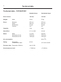
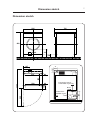
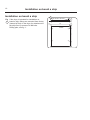
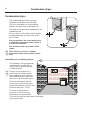
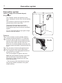
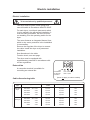
Installation manual
T4130
Compass Control
487 05 41 61.00
EN
Safety instructions
Safety instructions
This machine is only intended for drying water-washed
garments.
Clothes that have been cleaned with chemicals/inflammable
liquids, must NOT be dried in the machine.
Remove clothes from the tumble dryer as soon as they are dry.
This prevents them from becoming creased, and reduces the
risk of spontaneous ignition.
The machine must not be used for drying foam rubber or
foamlike materials.
The machine must not be used for drying floor mops*.
The machine must not be used by minors.
The machine must not be hosed down with water.
Mechanical, electrical and gas installations must only be
carried out by authorised personnel.
If the machine has a fault, this must be reported as soon as
possible to the person in charge. This is important for your
own safety and for the safety of others.
Gas dryers only:
The machine is not to be installed in rooms containing cleaning
machines with perchloroethylene, TRICHLOROETHYLENE or
CHLOROFLUOROCONTAINING HYDROCARBONS as cleaning
agents.
What to do if you smell gas:
Do not try to light any appliance.
Do not touch any electrical switch; do not use any phone in
your building.
Evacuate the room, building or area.
Contact the laundry manager.
* Applies only to floor mops containing polypropylene.
The dryer must not be installed behind a lockable door or a
sliding door. In the rooms where the dryer is to be installed the
door hinges must be on the outer side.
3
Contents
Contents
Technical data . . . . . . . . . . . . . . . . . . . . . . . . . . . . . . . . . . . . . . . . . . . . . . 6
Dimension sketch . . . . . . . . . . . . . . . . . . . . . . . . . . . . . . . . . . . . . . . . . . . 7
Unpacking . . . . . . . . . . . . . . . . . . . . . . . . . . . . . . . . . . . . . . . . . . . . . . . . . 8
Positioning . . . . . . . . . . . . . . . . . . . . . . . . . . . . . . . . . . . . . . . . . . . . 8
Mechanical installation. . . . . . . . . . . . . . . . . . . . . . . . . . . . . . . . . . . 8
Floor mounting. . . . . . . . . . . . . . . . . . . . . . . . . . . . . . . . . . . . . . . . . 8
Door reversal. . . . . . . . . . . . . . . . . . . . . . . . . . . . . . . . . . . . . . . . . . . . . . . 9
Installation on board a ship. . . . . . . . . . . . . . . . . . . . . . . . . . . . . . . . . . . 10
Washing column . . . . . . . . . . . . . . . . . . . . . . . . . . . . . . . . . . . . . . . . . . . 11
Condensate dryer . . . . . . . . . . . . . . . . . . . . . . . . . . . . . . . . . . . . . . . . . . 12
Installation of ventilating system . . . . . . . . . . . . . . . . . . . . . . . . . . 12
Changing over condensate dryers. . . . . . . . . . . . . . . . . . . . . . . . . 13
Evacuation system . . . . . . . . . . . . . . . . . . . . . . . . . . . . . . . . . . . . . . . . . 14
Air principle . . . . . . . . . . . . . . . . . . . . . . . . . . . . . . . . . . . . . . . . . . 14
Fresh air. . . . . . . . . . . . . . . . . . . . . . . . . . . . . . . . . . . . . . . . . . . . . 14
Exhaust duct . . . . . . . . . . . . . . . . . . . . . . . . . . . . . . . . . . . . . . . . . 15
Electric installation . . . . . . . . . . . . . . . . . . . . . . . . . . . . . . . . . . . . . . . . . 17
Function check. . . . . . . . . . . . . . . . . . . . . . . . . . . . . . . . . . . . . . . . . . . . . 18
The manufacturer reserves the right to modify design and
material specifications without notice.
5
6
Technical data
Technical data - T4130/4130C
Drum volume
Standard dryer
Condensate dryer
130 liter
130 liter
Weight:
Netto
54 kg
57 kg
Drum:
Diameter
Depth
Revolutions
G-factor
575 mm
500 mm
53 rpm
0.9
575 mm
500 mm
53 rpm
0.9
Capacity:
6 kg
6 kg
Heat effect:
5,1 / 3,2 kW
3,0 kW
0,13 kW
2730 rpm
3330 rpm
0,20 kW
2730 rpm
3330 rpm
Motor:
Effect
Revolutions 50 Hz
Revolutions 60 Hz
260 m3/h
Air consumption:
Piping:
Evacuation
Condensation water
Ø 100
1/2" hose to drain
Pressure drop: Evacuation 50/60 Hz
max. 60 Pa
Sound pressure level:
< 70 dB (A)
< 70 dB (A)
7
Dimension sketch
Dimension sketch
595
735
850
Ø 100
310
100
197
78
78
44
402
510
Connecting branch condensate dryers only
fl 14
550
Exhaust duct standard dryers
only
115
235
49
105
1260
500
8
Unpacking
Unpacking
1
Unpack the dryer from the packaging.
There are no transportation fittings. Release
the dryer from the pallet by cutting the plastic
ribbon.
Positioning
Fig Place the dryer in such a way that work can
1 be done as easily as possible by the user as
well as the service technician. The door is
reversible.
The distance to the wall or other equipment
behind the dryer should be min. 300 mm and
the distance to the sides min. 70 mm (if the
dryer is to be equipped with a coin box the
width of the coin box must also be added).
However, for the purpose of servicing the dryer
there should be free access to the back of it.
2
The dryer can be positioned on a 55-litre
washing machine to form a washing column.
Mechanical installation
Fig Adjust the dryer to ensure that it is horizontal
2 and stands firmly on all 4 feet.
The max. height adjustment is 14 mm.
Floor mounting
Fig The dryer can be installed directly on the floor
3 and fastened by means of the accompanying
cups A.
3
510
42,5 Alt. 1
15,5
564
15,5 Alt. 2
Alt. 1
122
A drilling plan is given in fig. 3
in the form of alternative 1 (from
the rear) or 2 (from the side),
depending on the space for
mounting the rocker brackets B.
42,5
95
Fasten the cups by means of the
screws.
Alt. 2
B
375
A
47,5
500
47,5
133
133
Front
Alt. 2
Alt. 1
402
Drill the rawlplug holes using a 10
mm drill.
9
Door reversal
Door reversal
1. Disconnect the power supply to the dryer.
2. Loosen the hinge mounting and push it down to
allow the door to be lifted off. Unscrew the hinge
mounting.
NB! Hold the door securely while loosening the
screws.
3. Unscrew the
cover screws at
the opposite
side and loosely
mount the hinge
mounting.
Screw in the
cover screws
where the hinge
was previously
mounted.
Lower pivot
Upper pivot
TOP
4. Remove the three black plugs at the top of the
door.
5. Dismount the handle by loosening the three screws.
6. Remove the pivot at the top to the other side.
7. Mount the handle at the opposite side where the
plugs used to be.
8. Insert the plugs where the handle used to be.
9. Remove the bottom pivot to the other side.
10. Release the locking plates by loosening the barb
with a screwdriver.
11. Press out the locking plates, swap them over and
press into position.
A
TOP
12. Mount the door. Push the hinge mounting
upwards and tighten the screws.
13. Test the door (use washers to adjust the hinge if
necessary). Check that door pin (A) is aligned
with the microswitch aperture.
14. Connect the power to the dryer. Finally, check
that the dryer stops when the door is opened.
Installation on board a ship
Installation on board a ship
28
12,5
573
Front
12,5
100
Drilling plan, see fig. 1.
M8
416
Fig If the dryer is intended for installation on
1 board a ship, fittings are mounted from factory
(instead of feet) on the dryer for attachment to
the ship floor by means of 4 M8 bolts.
1
175
10
11
Washing column
Washing column
The dryer can be installed on top of a 55-litre
washing machine WE455H or on a 130-litre
dryer T4130(C).
1
The washer at the bottom must be levelled
and rest on all four feet.
A
Fig • Place the frame on the top plate of the
1 lower machine, ensuring that the holes for the
fastening bracket A are at the rear.
• Screw the dryer feet of the upper machine all
the way home to ensure that they do not touch
the top plate of the lower machine.
• Lift the dryer into position, thereby making
sure that the machine fronts are flush.
Fig • As a protection against tilting, the two
2 accompanying plate screws are to be inserted
in either side in holes B.
• If holes B are not provided in the side plates,
drill them with a 3.3 mm drill.
Note! If it is hard to read the display adjust
the contrast in the service menu (see the
programming manual supplied with the dryer.
2
B
12
Condensate dryer
Condensate dryer
1
The condensate dryer does not have
ventilation (evacuation) into the open.
The air is circulated in a closed system
between the dryer and condensing unit.
The water in the garments condenses in the
condensing unit.
All the energy (3,4/2,4 kW) used for drying
the garments ends up in the room in the
form of heat.
During operation, the room experiences
a temperature increase, which results in
a need for ventilation.
The moisture ends up as water in the
drains.
Fig Note! The hose must be "sloping"
1 towards the drain and not form a water
trap.
Installation of ventilating system
2
For ventilation, a thermostatically
controlled fan, type EQ 250, is
used. It can be ordered as item
no. 988 80 20 43.
Fig The fan is to be placed on a
2 wall facing the outside behind
the condensate dryer, while the
thermostat is placed further into
the room in an accessible place.
The fresh air intake must end
in the room in front of the dryer,
positioned diagonally from the fan.
Pressure drop max.: 10 Pa.
The fresh air requirement
per dryer is 750 m3/h (if the
temperature is kept constant).
The need for fresh air varies and is controlled
by the thermostat.
13
Condensate dryers
Changing over condensate dryers
To be carried out by qualified personnel
3 x 400/415V + N 3,4kW
3 x 200/230/240V 3,4kW
B1
B1
1 x 230/240V 3,4kW
B1
Applies to all dryer types
14
Evacuation system
Evacuation system
1
(does not apply to condensate dryers)
Air principle
A
The ventilator creates low pressure in the
dryer, drawing air into the drum via the heating
unit.
5xA
The heated air passes through the garments
and the holes of the coarse filter.
Then the air flows through a lint screen
positioned in the door. After this, the air is
evacuated through the fan and the evacuation
system.
It is very important that the dryer gets enough
fresh air, see next section.
Fresh air
Fig For the machine to work optimally with the
1 shortest possible drying time, it is important
for the air input to the room to come from an
aperture from outside through which the same
amount of air is taken into the room as is
blown out. To avoid a draught in the room, the
air inlet should preferably be placed behind the
dryer.
Fig The free area* of the air inlet aperture must
be five times the area of the exhaust duct.
2
The resistance in the grating/slats should not
exceed 10 Pa (0.1 mbar).
The air consumption is approx. 260 m3/h.
Note that grates/slatted openings often block
half the total area of the fresh air intake.
Remember to make allowance for this fact
when dimensioning.
* The free area is the area which the air can
flow through without resistance from grate/
slatted opening.
2
5xA
15
Evacuation system
Exhaust duct
• The exhaust duct must be smooth on the
inside (low air resistance).
• The exhaust duct must lead to the outdoors.
• The exhaust duct must lead clear of the
building as condensation may cause frost
damage to the building.
• The exhaust duct must be protected against
rain and foreign objects.
Fig • The exhaust duct must have gentle bends.
1
• The exhaust duct must not be a shared duct
between dryers and appliances using gas or
other fuels as their energy source.
When several dryers share an exhaust duct
Fig • The exhaust duct diameter must increase after
each dryer.
2
The table below shows the exhaust duct
diameter and the necessary fresh-air inlet area.
Note! It is recommended that each dryer is
connected to a separate exhaust duct.
The exhaust duct
diameter must not
be reduced.
** If the exhaust duct lenght exceeds 6 m the diameter must be increased.
No. of
dryers
Exhaust
m3/h
d
mm
Fresh air inlet
cm2
Exhaust duct
lenght 0-6m d
**Exhaust duct
lenght 6-50m d
1
260
ø100
400
ø100
ø160
2
520
ø100
800
ø160
ø200
3
780
ø100
1200
ø200
ø250
4
1040
ø100
1600
ø250
ø350
16
Evacuation system
Exhaust duct
Gentle bends
1
Several dryers share an exhaust duct
2
17
Electric installation
Electric installation
To be carried out by qualified personnel
The dryer must be given a fuse group of its
own and switch in accordance with IEC 60947.
For each dryer, a multi-pole permanent switch
is to be placed in the permanent installation. It
must be easily accessible, but there must be
no mistaking it for the operating switch for the
dryer.
The motor features an integrated thermal fuse,
which is why motor protection in the installation
is unnecessary.
Remove the top plate of the dryer to connect
the cable. Install the dryer as a permanent
installation.
See dimensions in the table.
Function check, see next page.
The dryer must be equipped with
supplementary protection in accordance with
current regulations.
External fan
A connection terminal is available for
controlling an external fan.
Connection
of external
contactor
(Does not apply to marine models)
Cable dimensioning table
Type
Standard
dryer
Condensate dryer
Voltage
Ext. connection
Max. 1,25A
Powerintake
Heating
Fuse
400-440V
3N / 3 AC
5,3 kW
5,1 kW
10A
200-240V
3 AC
5,3 kW
5,1 kW
16A
230-240V
3 AC
3,4 kW
3,2 kW
10A
230-240V
1 AC
3,4 kW
3,2 kW
16A
400-440V
3N / 3 AC
3,4 kW
3,0 kW
10A
230-240V
3 AC
3,4 kW
3,0 kW
10A
230-240V
1 AC
3,4 kW
3,0 kW
16A
000-200V
3 AC
3,4 kW
3,0 kW
16A
18
Function check
Function check
To be carried out by qualified personnel
Check whether the drum is empty and the door
has been closed.
Start the dryer
Check whether the door lock is working:
The drum must stop if the loading door is
opened.
Fig The dryer has a single phase motor, which
1 is why the direction of rotation (clockwise) is
always correct.
Marine version
For dryers on board a ship (3-phase motor) the
direction of rotation must be checked.
If the direction of rotation is not correct, swop
two phases on the connection terminal.
Final test
Let the dryer work for 5 minutes on a program
that requires heat.
Then check whether the heating is working by
opening the front door and feel the heat.
If the above tests-points are in order, the dryer
is ready for use.
Service organisation/dealer
If deficiencies or errors are detected, please
contact your local service organisation/dealer.
1
www.electrolux.com/professional
Share more of our thinking at www.electrolux.com
about | case studies | contact
0845 077 65 65
Home
Laundry Equipment
Ozone Laundry Systems
Chemicals
Services
Special Offers
Ex Rental
Testimonials
Contact Us