1
Installation manual
T4300S
487 23 10 61.05
EN
2
Installation manual
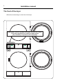
The front of the dryer
Affixed the enclosed sign on the front of the dryer.
CAUTION! Remove clothes from dryer as soon as it stops.
This keeps wrinkles from setting in and reduces
the possibility of spontaneous combustion
CAUTION! Remove clothes from dryer as soon as it stops.
This keeps wrinkles from setting in and reduces
the possibility of spontaneous combustion
487 01 29 00.01
487 01 29 00.0
Tumble dryer
Safety instructions
This machine is only intended for drying water-washed
garments.
Clothes that have been cleaned with chemicals/flammable
liquids, must NOT be dried in the machine.
Remove clothes from the tumble dryer as soon as they are dry.
This prevents them from becoming creased, and reduces the
risk of spontaneous ignition.
The machine must not be used for drying foam rubber or foamlike materials.
The machine must not be used for drying floor mops*.
The machine must not be used by minors.
The machine must not be hosed down with water.
Mechanical, electrical and gas installations must only be
carried out by authorised personnel.
Report machine malfunctions to qualified service personnel as
soon as possible. This is important for your own safety and for
the safety of others.
Gas dryers only:
The machine is not to be installed in rooms containing cleaning
machines with perchloroethylene, TRICHLOROETHYLENE or
CHLOROFLUOROCONTAINING HYDROCARBONS as cleaning
agents.
What to do if you smell gas:
Do not try to light any appliance.
Do not touch any electrical switch; do not use any phone in
your building.
Evacuate the room, building or area.
Contact appropriate authorities.
*Applies only to floor mops containing polypropylene.
The dryer must not be installed behind a lockable door or a
sliding door. In the rooms where the dryer is to be installed
the door hinges must be on the outer side.
3
Tumble dryer
Contents:
Dimension sketch . . . . . . . . . . . . . . . . . . . . . . . . . . . . . . . . . . . . . . . . . . 7
Technical data . . . . . . . . . . . . . . . . . . . . . . . . . . . . . . . . . . . . . . . . . . . . . 8
Setup, positioning . . . . . . . . . . . . . . . . . . . . . . . . . . . . . . . . . . . . . . . . . 10
Unpacking . . . . . . . . . . . . . . . . . . . . . . . . . . . . . . . . . . . . . . . . . . . . . . . 12
Evacuation system . . . . . . . . . . . . . . . . . . . . . . . . . . . . . . . . . . . . . . . . 14
Evacuation dimension . . . . . . . . . . . . . . . . . . . . . . . . . . . . . . . . . . . . . . 15
Gas installation . . . . . . . . . . . . . . . . . . . . . . . . . . . . . . . . . . . . . . . . . . . 17
Electric installation . . . . . . . . . . . . . . . . . . . . . . . . . . . . . . . . . . . . . . . . 21
External connection. . . . . . . . . . . . . . . . . . . . . . . . . . . . . . . . . . . . . . . . 22
Electric installation Electrical heated. . . . . . . . . . . . . . . . . . . . . . . . . . . 23
Function check . . . . . . . . . . . . . . . . . . . . . . . . . . . . . . . . . . . . . . . . . . . 25
Options: Adapter for direct fresh-air intake . . . . . . . . . . . . . . . . . . . . . . 26
The manufacturer reserves the right to modify design, material and
specifications without notice.
5
7
Installation manual
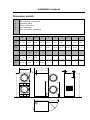
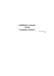
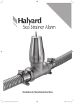
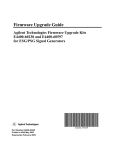
Dimension sketch
1
2
3
4
5
Door opening = Ø 580 mm
Operating panel
Electric connection
Gas connection
Pipe connection, evacuation
A
B
mm
790
inch
31 1/8"
L
C
1110
1960
30
inch
1 3/16"
105
4 1/8"
E
1270
43 3/4" 77 1/4"
M
mm
D
1210
50"
N
O
1840
740
72 1/2"
29 1/8"
A
47 5/8"
F
G
320
260
12 5/8"
10 1/4"
H
J
910
K
140
35 7/8"
1930
5 1/2"
76"
B
J
H
5
L
5
3+4
3
4
1
M
2
C
2
K
E
D
1
F
G
N
5
O
3
4
8
Installation manual
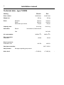
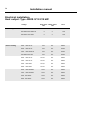
Technical data - type T4300S
Heating
Electric
Drum volume:
Weight net:
Drum:
Diameter
Depth
Revolutions per minute
Capacity, max:
Heat effect:
Electric
Gas
2x300 litres
2x300 litres
282 kg
282 kg
760 mm
660 mm
45 rpm
760 mm
660 mm
45 rpm
2x13.6 kg
2x13.6 kg
2x9 kW/2x13,5 kW/2x18 kW
Gas
2x21 kW
Air consumption:
2x600 m3/h
2x600 m3/h
Pipe connection:
Evacuation
Ø 200
Ø 200
Drop in pressure:
Evacuation max.
400 Pa
400 Pa
Gas pipe connection:
Gas pressure:
Noise level:
ISO 7/1-R1/2
See page regarding gas pressure
< 70 dB (A)
< 70 dB (A)
-
Installation manual
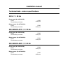
Technical data - motor specifications
230V / 1 / 50 Hz
Drum motor (No. 487028125):
Effect
Revolutions per minute:
430W
2760 rpm
Blower motor (No. 487028124):
Effect
Revolutions per minute:
520W
2830 rpm
200-240/400-415V / 3 / 50 Hz
Drum motor (No. 487028126):
Effect
Revolutions per minute:
520W
2700 rpm
Blower motor (No. 487028126):
Effect
Revolutions per minute:
520W
2700 rpm
200-240/400-480V / 3 / 60 Hz
Drum motor (No. 487028126):
Effect
Revolutions per minute:
520W
3300 rpm
Blower motor (No. 487028126):
Effect
Revolutions per minute:
520W
3300 rpm
9
10
Installation manual
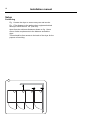
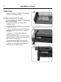
Setup
Positioning
Fig, 1 Locate the dryer to ensure easy use and service.
Fig. 1 The distance to the wall or other equipment behind
the dryer should be min. 20” (500 mm).
Apart from the minimum distances shown on fig. 1 there
are no further requirements to the distance around the
dryer.
There should be free access to the back of the dryer for the
purpose of servicing.
500
1
0
0
Installation manual
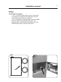
Setup
Connection to network
1. Fig. 1 If several tumble dryers are to be connected
to a network, the plugs A in the side panels must be
removed before the dryers are installed.
2. Fig. 2 A bushing for network cables must be installed
from the inside in the right-hand side panel. The
bushing must be pushed right through the hole in the
left-hand side panel on the side of the dryer.
1
2
A
11
12
Installation manual
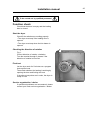
Unpacking
1
Handle the machine carefully when unpacking.
There are no transport fittings.
Remove the dryer from the pallet
At least 2 people are required to remove the
dryer from the pallet.
The dryer is secured to the pallet with 3
transport screws.
1. Open the filter door. Remove the 2 transport
screws at the front.
2. Remove the lower rear panel. Remove the
transport screw by the rear panel. Install the
rear panel.
2
3. Position a 1 1/2” steel pipe behind the
tumbler as shown in fig. 1.
4. Stand behind the dryer and tilt it forwards.
When the tumbler releases the pallet, push the
pipe under the tumbler. Fig. 2.
5. Push the tumbler from in front so that it
hangs over the rear edge of the pallet. Fig. 3.
6. Remove the steel pipe by tilting the dryer
forwards and removing the pipe.
3
13
Installation manual
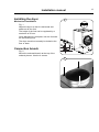
Installing the dryer
1
Mechanical installation
Fig. 1
Adjust the dryer so that it is horizontal and
stable on all four feet.
The height of the feet can be regulated by a
maximum of 50 mm.
Once adjustment is complete, lock the feet with
the self-locking nuts.
The dryer should not normally be bolted to the
floor or base.
A
A
A
A
Connection branch
A
A
Fig. 2
Mount the enclosed branch at the top of the
exhaust plenum. Use the 4 screws.
2
14
Installation manual
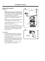
Evacuation system
1
Fresh air
Fig. 1
In order for the dryer to work optimally with the
shortest possible drying time, it is important for
the air supply to the room to take place through
a vent to the open air, with the same amount of
air being brought in as is evacuated.
A
5xA
In order to avoid draughts in the room, it is best
to position the air inlet behind the tumbler.
Fig. 2
The free area* at the intake air opening must be
5 times larger than the vent pipe’s area.
T3300S
487 19 24 05.01
The air resistance in the grate / louvre must not
exceed 10 Pa (0.1 mbar).
Max. air consumption 2 x 600 m3/h.
*The free area is the area through which the air
can flow without resistance from fins / louvres.
Note that fins / louvres often block half the total
area of the fresh air hole. Remember to take
this into account.
2
Air principle
The blower creates low pressure in the dryer,
drawing air into the drum via the heating unit.
The heated air passes through the garments
and the cylinder vents.
The air then flows out through a lint filter (filter
drawer) positioned immediately below the drum.
After this, the air is evacuated through the fan
and exhaust system.
It is very important for the tumbler to receive
plenty of fresh air, see next section.
5xA
487 19 24 05.01
15
Installation manual
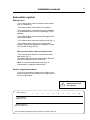
Evacuation system
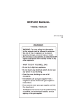
Exhaust duct
• The exhaust duct must be smooth on the inside
(low air resistance).
• The exhaust duct must lead to the outdoors.
• The exhaust duct must lead clear of the building
as condensation may cause frost damage to the
building.
• The exhaust duct must be protected against rain
and foreign objects.
• The exhaust duct must have gentle bends (fig. 1).
• The exhaust duct must not be a shared duct
between dryers and appliances using gas or other
fuels as their energy source.
When several dryers share an exhaust duct:
• The exhaust duct diameter must increase after
each dryer (fig. 2).
The table below shows the exhaust duct diameter
and the necessary fresh-air inlet area.
Note! It is recommended that each dryer is
connected to a separate exhaust duct.
Service organization/dealer
If you have questions relating to the design of the
exhaust system, please contact your local dealer or
service organization.
The evacuation pipe
diameter must not
be reduced.
No. of dryers
Exhaust duct
diameter in mm
Minimum area of
fresh-air intake in m2
1
2
3
4
5
6
7
8
9
10
200
280
315
355
400
450
475
500
535
560
0.15
0.30
0.45
0.60
0.75
0.90
1.05
1.20
1.35
1.50
Each machine requires a fresh-air aperture of 400 x 400 mm
16
Installation manual
Evacuation system
Gentle bends
1
Several dryers on a shared exhaust duct
2
17
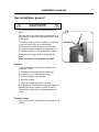
Installation manual
Gas installation general
To be carried out by
qualified personnel
Fig. Mount a shut-off valve upstream from the
dryer.
The gas line to the dryer must be designed for a
power supply of 2x21 kW, dependent on the size
of the dryer.
The factory nozzle pressure setting corresponds
to the fuel value given on the data label.
Check that the nozzle pressure and fuel value
correspond with the values in the gas tables on
the following pages. If not, contact the supplier.
Bleed the pipe system before connecting the
dryer.
After connection, test all joints for leaks.
Test run
1. Screw until the measuring connection (2) is
loosened 1/4 turn.
2. Connect a manometer to the measuring
connection (2), see side with gas valve.
3. Select a program with heating.
4. Start the tumbler.
5. Check the nozzle pressure, see table.
Any adjustment is carried out using the regulator’s
adjusting screw (4) under the cover screw (3).
Check that the gas flame is steady and blue in
colour.
Function check
The function check is described in the back of this
manual.
1
A
18
Installation manual
Gas installation general
1
Converting to bottled gas / natural gas
If the machine is to be converted to another type
of gas, the gas nozzle must be replaced.
1. Remove the bracket A and nozzle
2. Mount the accompanying nozzle (1).
3. Loosen the measuring branch screw (2) 1/4
turn; connect a manometer to the measuring
branch (2).
A
4. Connect the power and select a heat
programme.
5. Start the dryer.
6. Set the nozzle pressure on setting screw (4)
under nipple (3).
7 Check that the gas flame burns evenly and
has a bluish colour.
8. Mount the cover screw (3).
The numbers in brackets refer to the page
regarding the gas valve.
Affixing the sign
See fig. 2.
2
CAUTION
A clothes dryer produces combustible
lint and should be exhausted outdoors.
See installation-instruction book.
THIS DRYER MUST BE EXHAUSTED
TO THE OUTDOORS.
INSTRUCTIONS
INSPECT EXHAUST DUCTING EVERY 6
MONTHS AND REMOVE LINT BUILDUP.
487 18 97 42.02
WARNING
PLUMBERS BEWARE WHEN PRESSURE
TESTING!!!
DRYER MUST NOT BE SUBJECTED TO
PRESSURE THAT EXCEEDS
1/2 psig (3.5kPa).
TO DO SO WILL CAUSE GAS LEAKS
WHICH CAN RESULT IN FIRE OR
EXPLOSION.
TO PROVIDE ADEQUATE COMBUSTION
AIR THE FRESH AIR INTAKE MUST BE
INSTALLED ACCORDING TO
THE INSTALLATION MANUAL.
487 22 26 52.00
GB Warning: Before obtaining access to terminals,
all supply circuits must be disconnected.
FR Avertissement : Avant d acc der aux bornes,
tous les circuits d alimentation doivent tre d connect s.
IT
Attenzione: prima di accedere ai morsetti,
scollegare tutti i circuiti di alimentazione.
DE Warnung: Bevor auf die Klemmen zugegriffen wird,
m ssen alle Versorgungskreise unterbrochen werden.
DK Advarsel: Alle forsyningskredse skal afbrydes,
f¿r der bnes for adgang til klemmerne.
SE Varning: All str mf rs rjning skall brytas,
innan elkopplingsboxen ppnas.
FI
Varoitus: kaikki sy tt virtapiirit on katkaistava
ennen liit nt jen paljastamista.
487 22 26 48.00
F r ej vert ckas
Do not cover
Nicht berdecken
Ne pas couvrir
M ikke overd kkes
Ei saa peitt
Non coprire
487 19 69 74.00
This machine has been converted to
XXXXXX
and adjusted according to
the installation manual
19
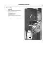
Installation manual
Gas valve
1. Nozzle
2. Measuring tap, nozzle pressure
3. Adjusting screw cap
4. Adjusting screw
5. Ignition control
6. Measuring tap, supply pressure
5
6
2
3+4
1
20
Installation manual
Note
Because of the differences in gas installation
regulations in European Union it is important
to use the Italian-language manual in Italy
and the French-language manual in France
ect.
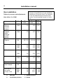
Gas installation
Tables of pressure and adjustments
Heat effect: 2 x 21kW
a
c
b
d
mbar
mbar
LPG
GNH
30
20
30
10.5
mm
2.20
3.80
LPG
GNH
28 / 37
20
28 / 37
10.5
2.20
3.80
LPG
GN
28 / 37
20 / 25
28 / 37
20 / 25
2.20
3.30
Germany
LPG
GNH
GNL
30 , 50
20
20
30
10.5
15.5
2.20
3.80
3.80
Holland
LPG
30
30
2.20
GNL
25
15.5
3.80
LPG
GNH
50
20
30
10.5
2.20
3.80
LPG
Propane
GN
30
30
2.20
30
18
18
30
10.5
15.2
2.20
3.80
3.80
Denmark
Norway
Sweden
Finland
Italy
England
Spain
Portugal
Ireland
Greece
France
Belgium
Austria
Japan
Australia
New Zealand
The rest of
the world
except: USA
LPG
GNH
GNL
a
Gas type
c Nozzle pressure
b
Connection pressure
d Nozzle
21
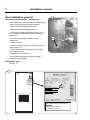
Installation manual
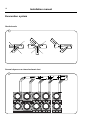
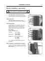
Electric installation - gas heated
To be carried out by qualified personnel
The tumble dryer must be connected to its
own fuse/miniature circuit-breaker group and
multipole switch in accordance with IEC 60947.
1
Cable dimension
When calculating the dimensions of the
connecting cable, refer to the local regulations.
Connecting power
A wiring diagram is included with each dryer
showing the wiring connection sequence.
Remove the back plate to connect through
supply entrance to the power terminal strip.
2
Gas heating:
1-phase 230-240V, fig. 1:
Top dryer:
Bottom dryer:
L1T = Phase
N1T = Neutral
L1B = Phase
N1B = Neutral
3-phase, fig. 2: Top- and bottom dryer
L1 = Phase
L2 = Phase
L3 = Phase
Fig. 3 Cables are installed with the aid of a
screwdriver.
3
Fuse / miniature circuit-breaker and output
The size of the fuse / miniature circuit-breaker
and the max. output of the tumble dryer can be
seen overleaf.
22
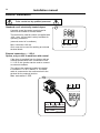
Installation manual
Electric installation
To be carried out by qualified personnel
External connection — 100 mA
Standard on all electrically heated dryers
1
A special screw joint and a terminal can be
found on the tumbler’s terminal board.
The terminal for external control is supplied with
110V / max. 100 mA and is solely intended for
operating contactors.
X1 X2 Gnd.
(external control of a ventilator)
Ext. connection
Max. 100mA
Max. connection 100 mA.
Gnd. must not be used for earthing an external
terminal board.
External connection — 1.25 A
Option, only on 400 V machines with neutral
If the dryer is supplied from the factory with an
external junction with max. connection of 230
V / 1.25 A, this junction can be used to connect
an external ventilator.
The cable to the external junction is installed
in contactor K7 in K7-2 and K7-4. The earth
cable is connected to the earth terminal in the
terminal for the external junction.
Max. connection 1.25A.
2
X1 X2 Gnd.
Ext. connection
Max. 100mA
N
230V
K7-2 K7-4 K7-6 K7-14
K7
External connection
Max. 1.25A 487 19 69 48.01
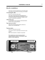
Installation manual
Electric installation
The dryer must be connected to its own fuse group
and multi-pole main switch according to IEC 60947.
Connecting the cable
Mount the enclosed cable gland.
The cable is led through the cable gland to the
terminal block and connected as illustrated. If there
is a neutral conductor in the power supply line this
must be connected to terminal N:
Cable dimension
For calculation of the connection cable dimension,
please refer to local guidelines.
Fuse group and effect
The sizes of the fuse group and the effect are
shown on the following page.
Function check
Mount the enclosed cover plate.
The function check is described in the back of this
manual.
NB: Correct direction of rotation is important!
The tumble dryer must be equipped with
supplementary protection in accordance with
heavy current regulations.
L1-L2-L3-N
Top
L1-L2-L3-N
Bottom
23
24
Installation manual
Electrical installation
Heat output: Type 4300S 9/13.5/18 kW
Voltage
Gas heating
Electric heating
Heat effect
kW
Motor effect
kW
Fuse
200-240V 3AC 50/60 Hz
0
2
10A
400-480V 3AC 50/60 Hz
0
2
10A
230-240V 1AC 50Hz
0
2
10A
230V 3AC 50 Hz
2x9
2x1
2x35A
400V 3AC 50 Hz
2x9
2x1
2x16A
415V 3AC 50/60 Hz
2x9
2x1
2x16A
440-480V 3AC 60h
2x9
2x1
2x16A
400V 3AC 50 Hz
2x13.5
2x1
2x25A
415V 3AC 50 Hz
2x13.5
2x1
2x25A
440V 3AC 60Hz
2x13,5
2x1
2x25A
480V 3AC 60Hz
2x13.5
2x1
2x20A
400V 3AC 50/60Hz
2x18
2x1
2x35A
415V 3AC 50/60Hz
2x18
2x1
2x35A
440V 3AC 60Hz
2x18
2x1
2x35A
480V 3AC 60Hz
2x18
2x1
2x25A
Installation manual
To be carried out by qualified personnel
Function check
Check that the drum is empty and the loading
door is closed.
Start the dryer
Check if the switches are working properly:
• The dryer must stop if the loading door is
opened.
• The dryer must stop when the lint drawer is
opened.
Checking the direction of rotation
Fig. 1.
Correct direction of rotation: clockwise.
Turn the terminal through 2 phases if the
direction of rotation is incorrect.
Final test
Let the dryer work for 5 minutes on a program
that requires heat.
Then check whether the heating is working by
opening the door and feeling the heat.
If the above test-points are in order, the dryer is
ready for use.
Service organisation / dealer
If operational problems are encountered, please
contact your local service organisation / dealer.
1
25
26
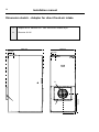
Installation manual
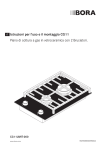
Dimension sketch - Adapter for direct fresh-air intake
1
Adapter kit no. 988 802 050 - Gas- and electric heated dryer.
2
Diameter Ø 315
1195 mm
210 mm
790 mm
140 mm
2
645 mm
1
1
395 mm
iVÌÀÕÝÊ>Õ`ÀÞÊ-ÞÃÌiÃÊ
Õ`ÌvÌi}>>À`ÃÛiÊÎ]ÊÓnääÊÞ}LÞ]Êi>ÀÊ
/ii«
i\ʳ{xÊ{xÓÈÊ{nää°Ê/iiv>Ý\ʳ{xÊ{xÓÈÊ{nä£Ê
ÌiÀiÌ\ÊÜÜÜ°iiVÌÀÕÝ°VÉ>Õ`ÀÞÃÞÃÌiÃÊ
>\ÊiðvJiiVÌÀÕÝ°V
about | case studies | contact
0845 077 65 65
Home
Laundry Equipment
Ozone Laundry Systems
Chemicals
Services
Special Offers
Ex Rental
Testimonials
Contact Us