1
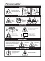
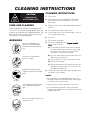
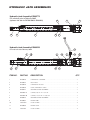
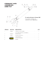
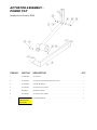
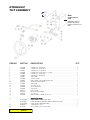
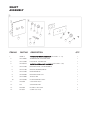
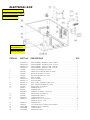
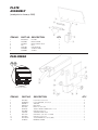
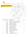
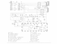
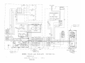
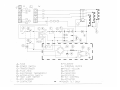
Operators Manual
Installation, Operation & Service
Skillets
OPEN BASE & MODULAR
ELECTRIC SKILLETS MODELS:
SEL-30-TR
SEL-40-TR
SEM-30-TR
SEM-40-TR
BULLET FOOT (FRONT) 078160-1
FLANGED FOOT (BACK) 078161-1
™
Cleveland
Enodis
1333 East 179th St., Cleveland, Ohio, U.S.A. 44110
Phone: (216) 481-4900 Fax: (216) 481-3782
Visit our web site at www.clevelandrange.com
SE95032 Rev. 5
FOR THE USER
WARNING:
!
Improper installation, adjustment, alteration, service or maintenance
can cause property damage, injury or death.
Read the Installation and Operating instructions thoroughly before
installing or servicing this equipment.
IMPORTANT
THE INSTALLATION AND CONNECTION MUST COMPLY WITH THE LOCAL AND
NATIONAL ELECTRICAL CODES.
ENSURE ELECTRICAL SUPPLY CONFORMS WITH ELECTRICAL CHARACTERISTICS
SHOWN ON THE RATING LABEL
ALL SERVICE MUST BE PERFORMED BY A QUALIFIED CLEVELAND RANGE
TECHNICIAN.
RETAIN THIS MANUAL FOR YOUR REFERENCE.
For your safety
DANGER
Keep hands and utensils
away from moving parts and
pinch points.
✘
✘
IMPORTANT
Do not lean
on or place
objects on
skillet lip.
Inspect unit
daily for
proper
operation.
Lift lid
before
tilting
skillet.
1
2
CAUTION
Wear protective equipment when
discharging hot product.
Stand clear of product
discharge path when
discharging hot product.
Surfaces may be
extremely hot! Use
protective equipment.
SERVICING
WARNING: Improper installation, adjustment,
alteration, service or maintenance can cause
property damage, injury or death. Read the
installation, operating and maintenance
instructions thoroughly before installing
or servicing this equipment.
Shut off power
at main fuse
disconnect
prior to
servicing.
Ensure skillet
is at room
temperature
prior to
servicing.
GAS APPLIANCES
Do not attempt to operate
this appliance during a
power failure.
Keep appliance and area free
and clear of combustibles.
INSTALLATION
GENERAL
Installation of the unit must be accomplished by
qualified electrical installation personnel working to all
applicable local and national codes. Improper
installation of product could cause injury or damage.
This equipment is built to comply with applicable
standards for manufacturers. Included among those
approval agencies are: UL, NSF, ASME/Ntl. Bd., CSA,
CGA, ETL, and others. Many local codes exist, and it is
the responsibility of the owner/installer to comply with
these codes.
SHIPPING DAMAGE
INSTRUCTIONS
If shipping damage to the unit is discovered or
suspected, observe the following guidelines in
preparing a shipping damage claim.
1. Write down a description of the damage or the
reason for suspecting damage as soon as it is
discovered. This will help in filling out the claim
forms later.
2. As soon as damage is discovered or suspected,
notify the carrier that delivered the shipment.
Note: Maximum voltage for LVD (low volt directive for
Europe) to be 440 volts for CE marked appliances.
3. Arrange for the carrier's representative to examine
the damage.
INSPECTION / UNPACKING
4. Fill out all carrier claims forms and have the
examining carrier sign and date each form.
Note: The electrical rating label is located on the frame
stiffener (right side) behind the front panel. For easy
access, remove the two screws securing the upper front
panel and hinge the lower front panel downwards. Serial
number, voltage, phase, amperage and wattage are
stated on this label.
1. Before unpacking visually inspect the unit for
evidence of damage during shipping.
2. If damage is noticed, do not unpack the unit, follow
"SHIPPING DAMAGE INSTRUCTIONS".
3. Carefully remove unit from shipping carton. Remove
any packing material from unit. After carefully
unpacking check for "concealed" damage. If
damage is noticed, follow "SHIPPING DAMAGE
INSTRUCTIONS".
4. Check the electrical rating label to ensure that the
unit is the correct voltage, phase, amperage and
wattage.
5. A protective material has been applied to the
stainless steel panels. This material must be
removed immediately after installation, as heat will
melt the material and make it more difficult to
remove.
CLEARANCE REQUIREMENTS
This unit must be installed in accordance with the
clearances shown on the rating label which is adhered
to the unit.
FOR YOUR SAFETY. Keep the appliance area free and
clear of combustible materials.
INSTALLATION
Note: For clearance requirements, suggested drain
location and assembly details refer to Specification
Sheet.
1. Position the unit in it's permanent location, and level
the unit by turning the adjustable feet.
2. Once positioned
4 7/8" (124mm)
and leveled,
permanently
120
120
secure the unit's
7/16"Ø, 3 HOLES
rear flanged feet to
ON 3 1/8" (80mm) B.C.D.
the floor using
5/16" lag bolts and
FLANGED FOOT DETAIL
(REAR LEGS ONLY)
floor anchors
(supplied by the
installer). Three
bolts are required to secure each of the flanged
feet.
3. Seal joints of flanged feet with a silicone sealant.
WIRE CONNECTION
WATER CONNECTION
Note: Ensure main power is turned off before
connecting wires.
(OPTIONAL)
General Information
Install in accordance with local codes and/or the
National Electric Code ANSI/NFPA No. 70-1990 (USA)
or the Canadian Electric Code CSA Standard C22.1
(Canada). A separate fused disconnect switch must be
supplied and installed. The unit must be electrically
grounded by the installer.
The electrical supply must match the power
requirements specified on the unit's rating label. The
copper wiring must be adequate to carry the required
current at the rated voltage. Wire must be suitable for at
least 194°F (90°C). Refer to Specification Sheet for all
electrical specifications. Cleveland strongly
recommends the use of liquid tight fittings.
Connection
NOTE: The supply lines will enter throght the rear (or
bottom) of the unit near the left side of the skillet and are
connected to the terminal block. For ease in attaching the
supply lines there is a removable cover on the wiring
compartment.
ENSURE THE ELECTRICAL SUPPLY MATCHES THE
UNIT'S REQUIREMENTS AS STATED ON THE
ELECTRICAL RATING LABEL.
NOTE: This skillet is factory wired for a 3 phase
installation. If single phase is required, check the wiring
diagram for proper modifications. The wiring diagram is
located on the back of the hinged front panel.
A 1/2" NPT cold water line and/or a 1/2" NPT hot water
line are required if unit is equipped with a single or
double pantry faucet.
INSTALLATION CHECKS
Although the unit has been thoroughly tested before
leaving the factory, the installer is responsible for
ensuring the proper operation of unit once installed.
1. Supply power to the unit by placing the fused
disconnect switch to the "ON" position.
2. Turn Temperature Dial to 150°F (66°C).
3. Toggle Power Switch to the "ON" position.
4. Heat Indicator Light (yellow) should be ON and unit
heating. When temperature is reached, Yellow
Indicator Light will switch OFF.
7. Turn Temperature Dial to 300°F (150°C). Unit will
continue to heat, Heat Indicator Light (yellow) will
remain ON until temperature is reached. Then the
heat indicator light will cycle off indicating the
heating system has shut OFF. The heat indicator
light will continue to cycle ON and OFF as the
heating system cycles ON and OFF maintaining the
desired temperature.
3. Toggle Power Switch to the "OFF" position.
CLEANING
After installation the unit must be thoroughly cleaned
and sanitized prior to cooking. See “CLEANING
INSTRUCTIONS” in this manual for complete cleaning
instructions.
OPERATING INSTRUCTIONS
3
2
1
CONTROL
PANEL
6
ITEM #
DESCRIPTION
FUNCTION
1.
On-Off Switch
Main power switch for unit.
2.
Power Indicator Light (Red)
Indicates power is on.
3.
Heat Indicator Light (Yellow)
Turns ON when system is calling for heat and
OFF when system is satisfied.
4.
Temperature Dial
Regulates the surface temperature of the pan.
5.
Power Tilt Switch
Used for tilting the pan up or down.
Some models have a Hand Tilt Wheel.
6.
Manual Tilt Override
Used on units with Power Tilt for tilting the pan up or down
in case of power or mechanical failure.
9.
Tangent Draw-Off Valve
(not shown)
Option - Used for draining product or wash water from kettle.
10.
Faucet
(not shown)
Option - hot and/or cold faucet mounts to skillet for
convenient filling of the pan.
4
5
OPERATING THE UNIT
1.
Ensure electrical supply to the unit is in the ON
position.
2.
Turn Power Switch to the ON position. The yellow
Heat Indicator Light will indicate power is on.
3.
MANUAL TILT: Cleveland skillets are equipped
with a manual tilt mechanism for raising and
lowering the pan. To raise pan, raise the cover and
turn the crank clockwise. To lower pan, turn
counterclockwise.
!
OPEN LID BEFORE
TILTING PAN
1
2
POWER TILT: Cleveland skillets can also be
equipped with an optional electric power tilt
mechanism for raising and lowering the pan. To
raise pan, raise the cover and press up on the tilt
switch. To lower pan, press down on the tilt switch.
4.
FOR YOUR SAFETY: This skillet is also
equipped with a power interrupter which
automatically shuts of the power to the elements
whenever the skillet is raised more than 1/2"
(13mm).
IMPORTANT: Before commencing to cook,
ensure pan is in the lowered position by pressing
down on the tilt switch. Ensure cover is raised first.
5.
To preheat, set Temperature Dial to desired
cooking temperature.
6.
Allow skillet to preheat for approximately 15-30
minutes.
7.
Once preheated, insert product in skillet and adjust
Temperature Dial to required cooking temperature.
8.
If desired, once product has cooked, it can be held
prior to serving at a lower temperature setting.
9.
When cooking is completed, set Temperature Dial
and Power Switch to the OFF position.
10. The best time to clean the skillet is immediately
after use, once skillet has cooled down. Refer to
section titled "CLEANING INSTRUCTIONS" for
details.
OPERATING SUGGESTION
1.
Turn power switch to the "OFF" position when skillet
is not in use.
2.
Allow skillet to preheat before adding product.
3.
Always lift the spring assist cover before activating
the tilt mechanism.
4.
During an electrical power interruption, turn Power
Switch to the OFF position. This unit cannot be
made to operate without electrical power.
HOT
CLEANING INSTRUCTIONS
CAUTION
SURFACES MAY
BE EXTREMELY HOT!
CARE AND CLEANING
Cooking equipment must be cleaned regularly to
maintain its fast, efficient cooking performance and
to ensure its continued safe, reliable operation. The
best time to clean is shortly after each use (allow
unit to cool to a safe temperature).
CLEANING INSTRUCTIONS
1. Turn unit off.
2. Remove drain screen (if applicable). Thoroughly
wash and rinse the screen either in a sink or a
dishwasher.
3. Prepare a warm water and mild detergent solution in
the unit.
4. Remove food soil using a nylon brush.
5. Loosen food which is stuck by allowing it to soak at
a low temperature setting.
6. Drain unit.
WARNINGS
➩
7. Rinse interior thoroughly.
Do not use detergents or
cleansers that are chloride
based or contain quaternary
salt.
Chloride Cleaners
➩
Do not use a metal bristle
brush or scraper.
8. If the unit is equipped with a Tangent Draw-Off
Valve, clean as follows:
a) Disassemble the draw-off valve first by turning
the valve knob counter-clockwise, then turning
the large hex nut counter-clockwise until the
valve stem is free of the valve body.
b) In a sink, wash and rinse the inside of the valve
body using a nylon brush.
c) Use a nylon brush to clean tangent draw-off tube.
d) Rinse with fresh water.
e) Reassemble the draw-off valve by reversing the
procedure for disassembly. The valve's hex nut
should be hand tight only.
Wire Brush &
➩
Steel wool should never be
used for cleaning the stainless
steel.
9. Using mild soapy water and a damp sponge, wash
the exterior, rinse, and dry.
NOTES
➩ For more difficult cleaning applications one of the
following can be used: alcohol, baking soda, vinegar,
or a solution of ammonia in water.
Steel Pads
➩
Unit should never be cleaned
with a high pressure spray
hose.
High Pressure
Spray Hose
➩
Do not leave water sitting in unit
when not in use.
Stagnant
Water
➩ Leave the cover off when the kettle is not in use.
➩ For more detailed instructions refer to the Nafem
Stainless Steel Equipment Care and Cleaning manual
(supplied with unit).
STAINLESS STEEL EQUIPMENT CARE AND CLEANING
(Suppied courtesy of Nafem. For more information visit their web site at www.nafem.org)
Contrary to popular belief, stainless steels ARE susceptible to rusting.
4. Treat your water.
Though this is not always practical, softening hard water can do much
to reduce deposits. There are certain filters that can be installed to
remove distasteful and corrosive elements. To insure proper water
treatment, call a treatment specialist.
Corrosion on metals is everywhere. It is recognized quickly on iron and
steel as unsightly yellow/orange rust. Such metals are called “active”
because they actively corrode in a natural environment when their atoms
combine with oxygen to form rust.
Stainless steels are passive metals because they contain other metals, like
chromium, nickel and manganese that stabilize the atoms. 400 series
stainless steels are called ferritic, contain chromium, and are magnetic;
300 series stainless steels are called austenitic, contain chromium and
nickel; and 200 series stainless, also austenitic, contains manganese,
nitrogen and carbon. Austenitic types of stainless are not magnetic, and
generally provide greater resistance to corrosion than ferritic types.
With 12-30 percent chromium, an invisible passive film covers the steel’s
surface acting as a shield against corrosion. As long as the film is intact
and not broken or contaminated, the metal is passive and stain-less. If the
passive film of stainless steel has been broken, equipment starts to
corrode. At its end, it rusts.
5. Keep your food equipment clean.
Use alkaline, alkaline chlorinated or non-chloride cleaners at
recommended strength. Clean frequently to avoid build-up of hard,
stubborn stains. If you boil water in stainless steel equipment,
remember the single most likely cause of damage is chlorides in the
water. Heating cleaners that contain chlorides have a similar effect.
6. Rinse, rinse, rinse.
If chlorinated cleaners are used, rinse and wipe equipment and
supplies dry immediately. The sooner you wipe off standing water,
especially when it contains cleaning agents, the better. After wiping
equipment down, allow it to air dry; oxygen helps maintain the
stainless steel’s passivity film.
Enemies of Stainless Steel
There are three basic things which can break down stainless steel’s
passivity layer and allow corrosion to occur.
7. Never use hydrochloric acid (muriatic acid) on stainless steel.
8. Regularly restore/passivate stainless steel.
1. Mechanical abrasion
2. Deposits and water
Recommended cleaners for specific situations
3. Chlorides
Job
Cleaning Agent
Comments
Mechanical abrasion means those things that will scratch a steel surface.
Steel pads, wire brushes and scrapers are prime examples.
Routine cleaning
Soap, ammonia,
detergent, Medallion
Apply with cloth or sponge
Fingerprints & smears
Arcal 20, Lac-O-Nu
Ecoshine
Provides barrier film
Stubborn stains &
discoloration
Cameo, Talc, Zud,
First Impression
Rub in direction of polish lines
Grease & fatty acids,
blood, burnt-on-foods
Easy-off, De-Grease
It Oven Aid
Excellent removal on all finishes
Grease & oil
Any good
commercial detergent
Apply with sponge or cloth
Restoration/Passivation
Benefit, Super Sheen
Water comes out of the faucet in varying degrees of hardness. Depending
on what part of the country you live in, you may have hard or soft water.
Hard water may leave spots, and when heated leave deposits behind that
if left to sit, will break down the passive layer and rust stainless steel. Other
deposits from food preparation and service must be properly removed.
Chlorides are found nearly everywhere. They are in water, food and table
salt. One of the worst chloride perpetrators can come from household and
industrial cleaners.
So what does all this mean? Don’t Despair!
Here are a few steps that can help prevent stainless steel rust.
1. Use the proper tools.
When cleaning stainless steel products, use non-abrasive tools. Soft
cloths and plastic scouring pads will not harm steel’s passive layer.
Stainless steel pads also can be used but the scrubbing motion must
be in the direction of the manufacturers’ polishing marks.
2. Clean with the polish lines.
Some stainless steel comes with visible polishing lines or “grain.”
When visible lines are present, always scrub in a motion parallel to the
lines. When the grain cannot be seen, play it safe and use a soft cloth
or plastic scouring pad.
Review
1. Stainless steels rust when passivity (film-shield) breaks down as a
result of scrapes, scratches, deposits and chlorides.
2. Stainless steel rust starts with pits and cracks.
3. Use the proper tools. Do not use steel pads, wire brushes or scrapers
to clean stainless steel.
4. Use non-chlorinated cleaners at recommended concentrations. Use
only chloride- free cleaners.
5. Soften your water. Use filters and softeners whenever possible.
6. Wipe off cleaning agent(s) and standing water as soon as possible.
Prolonged contact causes eventual problems.
3. Use alkaline, alkaline chlorinated or non-chloride containing cleaners.
While many traditional cleaners are loaded with chlorides, the industry
is providing an ever-increasing choice of non-chloride cleaners. If you
are not sure of chloride content in the cleaner used, contact your cleaner
supplier. If your present cleaner contains chlorides, ask your supplier if
they have an alternative. Avoid cleaners containing quaternary salts; it
also can attack stainless steel and cause pitting and rusting.
To learn more about chloride-stress corrosion and how to prevent it,
contact the equipment manufacturer or cleaning materials supplier.
Developed by Packer Engineering, Naperville, Ill., an independent testing
laboratory.
HYDRAULIC JACK ASSEMBLIES
Hydraulic Jack Assembly KE000772
For units built prior to February 2005
(replaces old Jack #s SK2381000 & SK00403)
2
5
1
3
6
7
6
Hydraulic Jack Assembly KE000523
11
For units built after February 2005
9
2
8
10
3
1
4
6
10
7
12
4
6
ITEM NO.
PART NO.
DESCRIPTION
QTY.
1
KE600526
HYDRAULIC CYLINDER . . . . . . . . . . . . . . . . . . . . . . . . . . . . . . . . . . . . . . . . . . .1
2
KE600527
PUSH ROD . . . . . . . . . . . . . . . . . . . . . . . . . . . . . . . . . . . . . . . . . . . . . . . . . . . . .1
3
KE600528
HYDRAULIC PISTON . . . . . . . . . . . . . . . . . . . . . . . . . . . . . . . . . . . . . . . . . . . . .1
4
KE600529
FORK, HYDRAULIC JACK . . . . . . . . . . . . . . . . . . . . . . . . . . . . . . . . . . . . . . . . .1
5
KE000771
GUIDE BUSHING ASSEMBLY . . . . . . . . . . . . . . . . . . . . . . . . . . . . . . . . . . . . . . .1
6
FA05002-41
O RING, 7/8 I.D. X 1 1/4 O.D. . . . . . . . . . . . . . . . . . . . . . . . . . . . . . . . . . . . . . . .2
7
FA05002-40
O RING, 1 3/16 I.D. X 1 3/8 O.D. . . . . . . . . . . . . . . . . . . . . . . . . . . . . . . . . . . . .1
8
KE000525
GUIDE BUSHING ASSEMBLY . . . . . . . . . . . . . . . . . . . . . . . . . . . . . . . . . . . . . . .1
9
KE600667
DRAIN TUBE . . . . . . . . . . . . . . . . . . . . . . . . . . . . . . . . . . . . . . . . . . . . . . . . . . . .1
10
F105220-4
HOSE CLAMP . . . . . . . . . . . . . . . . . . . . . . . . . . . . . . . . . . . . . . . . . . . . . . . . . . .2
11
KE600668
DRAIN HOSE . . . . . . . . . . . . . . . . . . . . . . . . . . . . . . . . . . . . . . . . . . . . . . . . . . . .1
12
F105220-1
HOSE CLAMP . . . . . . . . . . . . . . . . . . . . . . . . . . . . . . . . . . . . . . . . . . . . . . . . . . .2
HYDRAULIC JACK
ASSEMBLIES HAND TILT
For units built prior to October 2001
For complete assemblies see
HYDRAULIC JACK ASSEMBLIES.
ITEM NO.
PART NO.
DESCRIPTION
QTY.
1
2381000
HYDRAULIC JACK ASSEMBLY . . . . . . . . . . . . . . . . . . . . . . . . . . . . . . . . . . . . .1
(NO LONGER AVAILABLE, USE KE000772)
5
FA95007-7
RETAINING RING . . . . . . . . . . . . . . . . . . . . . . . . . . . . . . . . . . . . . . . . . . . . . . . .4
6
2376503
ACTUATOR PIN (FRONT) . . . . . . . . . . . . . . . . . . . . . . . . . . . . . . . . . . . . . . . . . .1
7
2357500
SLEEVE BEARING . . . . . . . . . . . . . . . . . . . . . . . . . . . . . . . . . . . . . . . . . . . . . . . .1
8
2376501
2376504
ACTUATOR PIN (REAR) . . . . . . . . . . . . . . . . . . . . . . . . . . . . . . . . . . . . . . . . . . .1
9
FA30505-3
WASHER . . . . . . . . . . . . . . . . . . . . . . . . . . . . . . . . . . . . . . . . . . . . . . . . . . . . . . .2
ACTUATOR ASSEMBLY POWER TILT
(used prior to January, 2000)
ITEM NO.
PART NO.
DESCRIPTION
QTY.
1.
SK2346100
ACTUATOR
2.
SK2337499
ACTUATOR MOUNTING BRACKET ASSY. . . . . . . . . . . . . . . . . . . . . . . . . . . . . .1
3.
SK2357600
SLEAVE BEARING . . . . . . . . . . . . . . . . . . . . . . . . . . . . . . . . . . . . . . . . . . . . . . . .1
4.
SK2376503
ACUATOR PIN, FRONT . . . . . . . . . . . . . . . . . . . . . . . . . . . . . . . . . . . . . . . . . . . .1
5.
FA95007-7
RETAINING RING . . . . . . . . . . . . . . . . . . . . . . . . . . . . . . . . . . . . . . . . . . . . . . . .1
6.
SK2376504
ACTUATOR PIN, REAR . . . . . . . . . . . . . . . . . . . . . . . . . . . . . . . . . . . . . . . . . . . .1
7.
FA95007-7
obsolete
no
replacement (no
longer used)
FLANGE BEARING . . . . . . . . . . . . . . . . . . . . . . . . . . . . . . . . . . . . . . . . . . . . . . .2
1
ACTUATOR ASSEMBLY POWER TILT
7
9
(used after January, 2000)
8
9
7
3
10
15
11
14
12
2
1
13
7
7
6
5
4
4
5
ITEM NO.
PART NO.
DESCRIPTION
1.
SK2346100
KE003242
SK2346100-1
SK2346101-1
KE603205
FA11091
FA05002-54
SK2337499
SK00352
SK2357500
SK2376503
FA95007-7
SK2376504
FA30505-3
KE601979
KE601960
KE602198
FA32005
F10
F12
KE002226
ACTUATOR ASSY., COMPLETE WITH ITEM 2 . . . . . . . . . . . . . . . . . . . . . . . . . .1
ACTUATOR ASSY., WITH MANUAL OVERRIDE, COMPLETE WITH ITEMS 2 & 3 . . .1
MOTOR . . . . . . . . . . . . . . . . . . . . . . . . . . . . . . . . . . . . . . . . . . . . . . . . . . . . . . . .1
MOTOR, WITH MANUAL OVERRIDE . . . . . . . . . . . . . . . . . . . . . . . . . . . . . . . . .1
COVER . . . . . . . . . . . . . . . . . . . . . . . . . . . . . . . . . . . . . . . . . . . . . . . . . . . . . . . .1
SCREWS, SS, 8-32 X 3/8 . . . . . . . . . . . . . . . . . . . . . . . . . . . . . . . . . . . . . . . . . .3
O-RING . . . . . . . . . . . . . . . . . . . . . . . . . . . . . . . . . . . . . . . . . . . . . . . . . . . . . . . .1
MOUNTING BRACKET, WITHOUT TANGENT DRAW-OFF VALVE ON PAN . . . .1
MOUNTING BRACKET, WITH TANGENT DRAW-OFF VALVE ON PAN . . . . . . .1
SLEEVE BEARING . . . . . . . . . . . . . . . . . . . . . . . . . . . . . . . . . . . . . . . . . . . . . . . .1
ACTUATOR PIN, LONG . . . . . . . . . . . . . . . . . . . . . . . . . . . . . . . . . . . . . . . . . . .1
RETAINING RING . . . . . . . . . . . . . . . . . . . . . . . . . . . . . . . . . . . . . . . . . . . . . . . .4
ACTUATOR PIN, SHORT . . . . . . . . . . . . . . . . . . . . . . . . . . . . . . . . . . . . . . . . . . .1
WASHER . . . . . . . . . . . . . . . . . . . . . . . . . . . . . . . . . . . . . . . . . . . . . . . . . . . . . . .2
LIMIT SWITCH . . . . . . . . . . . . . . . . . . . . . . . . . . . . . . . . . . . . . . . . . . . . . . . . . . .1
BRACKET, LIMIT SWITCH, WITHOUT TANGENT DRAW-OFF VALVE ON PAN .1
BRACKET, LIMIT SWITCH, WITH TANGENT DRAW-OFF VALVE ON PAN . . . . .1
LOCKWASHER, #8 . . . . . . . . . . . . . . . . . . . . . . . . . . . . . . . . . . . . . . . . . . . . . . .2
SCREW, #8-32X3/8 . . . . . . . . . . . . . . . . . . . . . . . . . . . . . . . . . . . . . . . . . . . . . . .2
SCREW, #10-24X1/2 . . . . . . . . . . . . . . . . . . . . . . . . . . . . . . . . . . . . . . . . . . . . . .2
KIT FOR UNITS BUILT PRIOR TO MARCH 2006 . . . . . . . . . . . . . . . . . . . . . . . .1
2.
3.
4.
5.
6.
7.
8.
9.
10.
11.
12.
13.
14.
15.
QTY.
HYDRAULIC
TILT ASSEMBLY
24
New
(added February
2005)
KE600452 (Strainer)
FI00351 (Bushing)
FI05318-1 (Elbow, hose
barb)
ITEM NO.
PART NO.
DESCRIPTION
1
2
3
4
5
6
7
8
9
10
11
12
13
14
15
16
17
19
2379100
2379600
2379501
2379500
2379000
2379001
2378901
2379400
2379301
2382700
2378900
2375699
2250700
2376200
078279-1
FA95079
FI05059
2379200
HYDRAULIC ADAPTOR . . . . . . . . . . . . . . . . . . . . . . . . . . . . . . . . . . . . . . . . . . .2
HYDRAULIC HOSE ASSY . . . . . . . . . . . . . . . . . . . . . . . . . . . . . . . . . . . . . . . . . .1
HYDRAULIC HOSE ASSY . . . . . . . . . . . . . . . . . . . . . . . . . . . . . . . . . . . . . . . . . .1
HYDRAULIC HOSE ASSY, 8” LONG . . . . . . . . . . . . . . . . . . . . . . . . . . . . . . . . . .1
HYDRAULIC ADAPTOR . . . . . . . . . . . . . . . . . . . . . . . . . . . . . . . . . . . . . . . . . . .1
HYDRAULIC ADAPTOR . . . . . . . . . . . . . . . . . . . . . . . . . . . . . . . . . . . . . . . . . . .1
TEE F/M/M . . . . . . . . . . . . . . . . . . . . . . . . . . . . . . . . . . . . . . . . . . . . . . . . . . . . . .1
CHECK VALVE . . . . . . . . . . . . . . . . . . . . . . . . . . . . . . . . . . . . . . . . . . . . . . . . . . .1
BALL VALVE C/W HANDLE AND NUT . . . . . . . . . . . . . . . . . . . . . . . . . . . . . . . .1
VALVE RETURN SPRING . . . . . . . . . . . . . . . . . . . . . . . . . . . . . . . . . . . . . . . . . .1
TEE M/F/M . . . . . . . . . . . . . . . . . . . . . . . . . . . . . . . . . . . . . . . . . . . . . . . . . . . . . .1
OIL TANK ASSY . . . . . . . . . . . . . . . . . . . . . . . . . . . . . . . . . . . . . . . . . . . . . . . . .1
PLUG (DRILLED) . . . . . . . . . . . . . . . . . . . . . . . . . . . . . . . . . . . . . . . . . . . . . . . . .1
LINK ROD . . . . . . . . . . . . . . . . . . . . . . . . . . . . . . . . . . . . . . . . . . . . . . . . . . . . . .1
BALL KNOB . . . . . . . . . . . . . . . . . . . . . . . . . . . . . . . . . . . . . . . . . . . . . . . . . . . .1
PUSH-ON FASTENER . . . . . . . . . . . . . . . . . . . . . . . . . . . . . . . . . . . . . . . . . . . . .1
1/2" TO 3/8 . . . . . . . . . . . . . . . . . . . . . . . . . . . . . . . . . . . . . . . . . . . . . . . . . . . . .1
ELBOW WITH O-RING 3/8 TO 1/4" . . . . . . . . . . . . . . . . . . . . . . . . . . . . . . . . . . .1
22
23
SK2378800
SK2378801
SK2378800
KE00508-1
FA19505
HYDRAULIC PUMP
USED PRIOR TO JANUARY 2002 . . . . . . . . . . . . . . . . . . . . . . . . . . . . . . . . . . . .1
USED BETWEEN JANUARY 2002 & FEBRUARY 2005 . . . . . . . . . . . . . . . . . . .1
USED AFTER FEBRUARY 2005 . . . . . . . . . . . . . . . . . . . . . . . . . . . . . . . . . . . . .1
HANDWHEEL ASSY . . . . . . . . . . . . . . . . . . . . . . . . . . . . . . . . . . . . . . . . . . . . . .1
SET SCREW 3/8-24 X 3/8 LONG . . . . . . . . . . . . . . . . . . . . . . . . . . . . . . . . . . . .1
24
SE00128
21
QTY.
CONTROL
PANEL
22
21
ITEM NO.
PART NO.
1
2474101
2474100
2343500
2343502
2343501
SK2533199
2138700
2360701
2360700
KE95586-1
KE95586-2
KE95586-3
KE95586-4
2356100
2356102
SE00119
2142002
2498399
SK50872-1
SK50872-2
F33
2147403
2147402
2147401
2147400
2352898
2353100
2383200
2357900
KE55069-7
SK00383-1
SK00383-2
SK00383-3
SK00383-4
SK50905-1
SK50905-2
SK50903
2
3
4
5
6
7
8
8A
8B
9
10
11
12
13
14
15
16
17
18
19
20
21
22
DESCRIPTION
QTY.
POWER SWITCH (240V, USED AFTER FEBRUARY 2001) . . . . . . . . . . . . . . . . . . . . . .1
POWER SWITCH (USED AFTER FEBRUARY 2001) . . . . . . . . . . . . . . . . . . . . . . . . . . .1
POWER SWITCH (USED PRIOR TO FEBRUARY 2001) . . . . . . . . . . . . . . . . . . . . . . . .1
TILT SWITCH (POWER TILT ONLY, USED AFTER FEBRUARY 2001) . . . . . . . . . . . . . .1
TILT SWITCH (POWER TILT ONLY, USED PRIOR TO FEBRUARY 2001) . . . . . . . . . . .1
FUSE, POLYSWITCH ASSY. . . . . . . . . . . . . . . . . . . . . . . . . . . . . . . . . . . . . . . . . . . . . . .1
DIAL KNOB . . . . . . . . . . . . . . . . . . . . . . . . . . . . . . . . . . . . . . . . . . . . . . . . . . . . . . . . . .1
DIAL INSERT °C . . . . . . . . . . . . . . . . . . . . . . . . . . . . . . . . . . . . . . . . . . . . . . . . . . . . . .1
DIAL INSERT °F . . . . . . . . . . . . . . . . . . . . . . . . . . . . . . . . . . . . . . . . . . . . . . . . . . . . . . .1
LABEL, CLEVELAND, MANUAL TILT . . . . . . . . . . . . . . . . . . . . . . . . . . . . . . . . . . . . . .1
LABEL, CLEVELAND, POWER TILT . . . . . . . . . . . . . . . . . . . . . . . . . . . . . . . . . . . . . . .1
LABEL, GARLAND, MANUAL TILT . . . . . . . . . . . . . . . . . . . . . . . . . . . . . . . . . . . . . . . .1
LABEL, GARLAND, POWER TILT . . . . . . . . . . . . . . . . . . . . . . . . . . . . . . . . . . . . . . . . .1
INDICATOR LIGHT, GREEN, USED PRIOR TO FEB. 2001 (ORDER SERVICE PART # SE00121) . . .1
INDICATOR LIGHT, AMBER, USED PRIOR TO FEB. 2001 (ORDER SERVICE PART # SE00131 . . .1
ELECTRONIC THERMOSTAT KIT (INCLUDES 8A & 8B) . . . . . . . . . . . . . . . . . . . . . . .1
ELECTRONIC THERMOSTAT . . . . . . . . . . . . . . . . . . . . . . . . . . . . . . . . . . . . . . . . . . . .1
SHAFT ASSY. . . . . . . . . . . . . . . . . . . . . . . . . . . . . . . . . . . . . . . . . . . . . . . . . . . . . . . . . .1
TERMINAL BLOCK . . . . . . . . . . . . . . . . . . . . . . . . . . . . . . . . . . . . . . . . . . . . . . . . . . . .18
TERMINAL END . . . . . . . . . . . . . . . . . . . . . . . . . . . . . . . . . . . . . . . . . . . . . . . . . . . . . . .3
SEALER WASHER . . . . . . . . . . . . . . . . . . . . . . . . . . . . . . . . . . . . . . . . . . . . . . . . . . . . .4
LIQUID-TIGHT FITTING 5/8" . . . . . . . . . . . . . . . . . . . . . . . . . . . . . . . . . . . . . . . . . . . . .1
LIQUID-TIGHT FITTING 3/8" . . . . . . . . . . . . . . . . . . . . . . . . . . . . . . . . . . . . . . . . . . . . .1
LIQUID-TIGHT FITTING 5/16" (POWER TILT ONLY) . . . . . . . . . . . . . . . . . . . . . . . . . . .1
LIQUID-TIGHT FITTING 3/16" . . . . . . . . . . . . . . . . . . . . . . . . . . . . . . . . . . . . . . . . . . . .1
CONTROL BOX ASSY. . . . . . . . . . . . . . . . . . . . . . . . . . . . . . . . . . . . . . . . . . . . . . . . . .1
CONTROL BOX COVER . . . . . . . . . . . . . . . . . . . . . . . . . . . . . . . . . . . . . . . . . . . . . . . .1
CONTROL COVER GASKET . . . . . . . . . . . . . . . . . . . . . . . . . . . . . . . . . . . . . . . . . . . . .1
NEOPRENE GASKET . . . . . . . . . . . . . . . . . . . . . . . . . . . . . . . . . . . . . . . . . . . . . . . . . .1
HIGH LIMIT . . . . . . . . . . . . . . . . . . . . . . . . . . . . . . . . . . . . . . . . . . . . . . . . . . . . . . . . . .1
CONTROL PANEL, POWER TILT, 40-TR . . . . . . . . . . . . . . . . . . . . . . . . . . . . . . . . . . . .1
CONTROL PANEL, POWER TILT, 30-TR . . . . . . . . . . . . . . . . . . . . . . . . . . . . . . . . . . . .
CONTROL PANEL, MANUAL TILT, 40-TR . . . . . . . . . . . . . . . . . . . . . . . . . . . . . . . . . . .1
CONTROL PANEL, MANUAL TILT, 30-TR . . . . . . . . . . . . . . . . . . . . . . . . . . . . . . . . . .1
INDICATOR LIGHT, USED AFTER FEB, 2001 (GAS MODELS) . . . . . . . . . . . . . . . . . .1
INDICATOR LIGHT, USED AFTER FEB, 2001 (ELECTRIC MODELS) . . . . . . . . . . . . . .1
BRACKET, USED AFTER FEB, 2001 . . . . . . . . . . . . . . . . . . . . . . . . . . . . . . . . . . . . . . .1
SHAFT
ASSEMBLY
1
4
2
5
6
7
11
8
12
3
13
9
10
DESCRIPTION
14
ITEM NO.
PART NO.
QTY.
1.
SE00119
THERMOSTAT BOARD ASSEMBLY (INCLUDES 2 - 14)
1
2.
SK2142002
TEMPERATURE SENSOR BOARD
1
3.
SK2159300
INSULATOR, THERMOSTAT
1
4.
SK2498399
POTENTIOMETER SHAFT ASSEMBLY (INCLUDES 5-10)
1
5.
SK2167200
RETAINING RING, SP-NR #R1000-25
1
6.
SK2167100
WASHER, BOWED/SPRING
1
7.
SK2167300
PANEL BEARING
1
8.
SK2382800
RETAINING RING CLIP
1
9.
SK2167000
TENSION PIN
1
10.
SK2166800
POTENTIOMETER SHAFT
1
11.
2491500
STOP PLATE ASSY.
1
12.
F33
SEALER WASHER
2
13.
KE51005
ROTARY SHAFT SEAL
1
14.
FA11054
SCREW 6-32 X 3/8
2
ELECTRICAL BOX
Component Box Cover 2343900
Component box assembly 2343699
Igniton cable SE50450
KE002226
REPLACEMENT KIT
Switch only KE601979
ITEM NO.
PART NO.
DESCRIPTION
1
12
13
14
15
KE53838-31
KE53838-30
KE53838-33
KE53838-15
1427305
2282100
1426600
KE50581
2320702
KE52936-10
KE52936-11
KE52936-13
KE52936-9
2147403
KE50377
KE50376
G01280-3-7
2147401
2348100
KE50750-7
SK50872-1
16
17
18
19
20
SK50872-2
SK50399
SK2347300
SK2383400
SK2372099
TRANSFORMER - POWER TILT 208 - 480V PT . . . . . . . . . . . . . . . . . . . . . . . . .1
TRANSFORMER - POWER TILT 220 - 415V PT . . . . . . . . . . . . . . . . . . . . . . . . .1
TRANSFORMER - HAND TILT 208 - 480V MT . . . . . . . . . . . . . . . . . . . . . . . . . .1
TRANSFORMER - HAND TILT 220 - 415V MT . . . . . . . . . . . . . . . . . . . . . . . . . .1
CAPACITOR (POWER TILT ONLY) . . . . . . . . . . . . . . . . . . . . . . . . . . . . . . . . . . .1
CAPACITOR CLAMP (POWER TILT ONLY) . . . . . . . . . . . . . . . . . . . . . . . . . . . . .1
RESISTOR (POWER TILT ONLY) . . . . . . . . . . . . . . . . . . . . . . . . . . . . . . . . . . . . .1
RECTIFIER (POWER TILT ONLY) . . . . . . . . . . . . . . . . . . . . . . . . . . . . . . . . . . . .1
FUSE HOLDER . . . . . . . . . . . . . . . . . . . . . . . . . . . . . . . . . . . . . . . . . . . . . . . . . .1
FUSE 1.5A/250V . . . . . . . . . . . . . . . . . . . . . . . . . . . . . . . . . . . . . . . . . . . . . . . . .1
FUSE 0.5A/250V . . . . . . . . . . . . . . . . . . . . . . . . . . . . . . . . . . . . . . . . . . . . . . . . .1
FUSE 1A AGC (POWER & HAND TILT) . . . . . . . . . . . . . . . . . . . . . . . . . . . . . . .1
FUSE 15A MDA (POWER TILT ONLY) . . . . . . . . . . . . . . . . . . . . . . . . . . . . . . . .1
LIQUID-TIGHT FITTING 5/8" . . . . . . . . . . . . . . . . . . . . . . . . . . . . . . . . . . . . . . . .1
TERMINAL BLOCK . . . . . . . . . . . . . . . . . . . . . . . . . . . . . . . . . . . . . . . . . . . . . . .3
TERMINAL END . . . . . . . . . . . . . . . . . . . . . . . . . . . . . . . . . . . . . . . . . . . . . . . . .1
TERMINAL CHANNEL - 3 BLOCKS . . . . . . . . . . . . . . . . . . . . . . . . . . . . . . . . . .1
LIQUID-TIGHT FITTING 5/16" . . . . . . . . . . . . . . . . . . . . . . . . . . . . . . . . . . . . . . .1
INTERRUPTER SWITCH . . . . . . . . . . . . . . . . . . . . . . . . . . . . . . . . . . . . . . . . . . .1
CONTACTOR 3 POLE . . . . . . . . . . . . . . . . . . . . . . . . . . . . . . . . . . . . . . . . . . . . .2
TERMINAL BLOCK - JUNCTION . . . . . . . . . . . . . . . . . . . . . . . . . . . . . . . . . . . .15
TERMINAL BLOCK - LINE . . . . . . . . . . . . . . . . . . . . . . . . . . . . . . . . . . . . . . . . .2
TERMINAL END . . . . . . . . . . . . . . . . . . . . . . . . . . . . . . . . . . . . . . . . . . . . . . . . .1
1/2" LIQUID-TIGHT CONNECTOR STRAIGHT . . . . . . . . . . . . . . . . . . . . . . . . . .3
TERMINAL BLOCK SUPPORT . . . . . . . . . . . . . . . . . . . . . . . . . . . . . . . . . . . . . .1
COVER GASKET . . . . . . . . . . . . . . . . . . . . . . . . . . . . . . . . . . . . . . . . . . . . . . . . .1
SERVICE BOX ASSY. . . . . . . . . . . . . . . . . . . . . . . . . . . . . . . . . . . . . . . . . . . . . . .1
2
3
4
5
6
7
8
9
10
11
QTY.
PLATE
ASSEMBLY
(used prior to January, 2000)
ITEM NO.
PART NO. DESCRIPTION
1
2
3
4
5
6
7
KE55069-7
2353900
2354099
F95
2345100
2344900
2345000
HI-LIMIT
BULB CLAMP
BULB SHIELD ASSY
NUT
RTD SENSOR
SHIELD LINER
SHIELD
QTY.
1
1
1
1
1
1
1
PAN HINGE
13 14
For units with TD Valve
ITEM NO.
PART NO.
DESCRIPTION
QTY.
1
2
3
4
5
6
7
8
9
11
13
14
FA21053
FA30505-3
078248-1
G02925-2
FA15015
FA10245
FA21004
2354199
FA11224
FA21024
FA15019-2
SK50813
LOCK NUT 1/2-13 S.S. . . . . . . . . . . . . . . . . . . . . . . . . . . . . . . . . . . . . . . . . . . . .2
LOCK WASHER 1/2-13 S.S. . . . . . . . . . . . . . . . . . . . . . . . . . . . . . . . . . . . . . . . .2
SPACER . . . . . . . . . . . . . . . . . . . . . . . . . . . . . . . . . . . . . . . . . . . . . . . . . . . . . . . .2
BUSHING . . . . . . . . . . . . . . . . . . . . . . . . . . . . . . . . . . . . . . . . . . . . . . . . . . . . . .2
BOLT 1/2-13 X 3/4" . . . . . . . . . . . . . . . . . . . . . . . . . . . . . . . . . . . . . . . . . . . . . . .2
TRUSS HEAD SCREW 8-32 X 1 S.S. . . . . . . . . . . . . . . . . . . . . . . . . . . . . . . . . .1
HEX NUT 8-32 S.S. . . . . . . . . . . . . . . . . . . . . . . . . . . . . . . . . . . . . . . . . . . . . . . .1
STRIKER PLATE ASSY . . . . . . . . . . . . . . . . . . . . . . . . . . . . . . . . . . . . . . . . . . . .1
HEX BOLT, 5/16-18 X 1" LONG . . . . . . . . . . . . . . . . . . . . . . . . . . . . . . . . . . . . . .1
HEX NUT 1/2-13 S.S. . . . . . . . . . . . . . . . . . . . . . . . . . . . . . . . . . . . . . . . . . . . . .1
SHOULDER BOLT, 1/2-13 (303) . . . . . . . . . . . . . . . . . . . . . . . . . . . . . . . . . . . . .2
BEARING HINGE . . . . . . . . . . . . . . . . . . . . . . . . . . . . . . . . . . . . . . . . . . . . . . . .2
SPRING ASSEMBLY
ITEM NO.
PART NO.
DESCRIPTION
QTY.
1
2452300
SPRING
2
2381700
TURNBUCKLE BODY . . . . . . . . . . . . . . . . . . . . . . . . . . . . . . . . . . . . . . . . . . . . . . . . . .2
3
2374900
CONNECTING ROD R/H THREAD . . . . . . . . . . . . . . . . . . . . . . . . . . . . . . . . . . . . . . . .2
2374901
CONNECTING ROD L/H THREAD . . . . . . . . . . . . . . . . . . . . . . . . . . . . . . . . . . . . . . . .2
4
2529499
BELL CRANK ASSY . . . . . . . . . . . . . . . . . . . . . . . . . . . . . . . . . . . . . . . . . . . . . . . . . . . .2
5
1082200
BOLT, 9/16-18 X 1-5/16 SHOULDER . . . . . . . . . . . . . . . . . . . . . . . . . . . . . . . . . . . . . . .2
6
F112
FLAT WASHER 3/8" I.D. . . . . . . . . . . . . . . . . . . . . . . . . . . . . . . . . . . . . . . . . . . . . . . . . .4
8
FA20500
NUT, 9/16-18, S.S. . . . . . . . . . . . . . . . . . . . . . . . . . . . . . . . . . . . . . . . . . . . . . . . . . . . . .2
9
2372400
BELL CRANK HOOK . . . . . . . . . . . . . . . . . . . . . . . . . . . . . . . . . . . . . . . . . . . . . . . . . . .2
. . . . . . . . . . . . . . . . . . . . . . . . . . . . . . . . . . . . . . . . . . . . . . . . . . . . . . . . . . . .2
PAN
(used prior to January, 2000)
SK00344-2 PAN WLDT SEL40TR (TD)
SK00344-1 PAN WLDT SEL40TR (NO TD)
ITEM NO.
PART NO.
DESCRIPTION
1
23563
23730
23562
23729
2364101
2364100
2360301
2360300
2364201
2364200
2360401
2360400
2382000
2381200
2381900
2381300
2382200
2381500
2382100
2381400
2364700
2372200
2364300
2364400
2274800
2274600
ELEMENT - CENTRE 4.8KW (SPECIFY VOLTAGE), 30 GAL. . . . . . . . . . . . . . .1
ELEMENT - SIDE 4.8KW (SPECIFY VOLTAGE) 30 GAL. . . . . . . . . . . . . . . . . . .2
ELEMENT - CENTRE 6.OKW (SPECIFY VOLTAGE) 40 GAL. . . . . . . . . . . . . . .1
ELEMENT - SIDE 6.OKW (SPECIFY VOLTAGE) 40 GAL. . . . . . . . . . . . . . . . . .2
ELEMENT CLAMP - CENTRE 30 GAL. . . . . . . . . . . . . . . . . . . . . . . . . . . . . . . . .1
ELEMENT CLAMP - SIDE 30 GAL. . . . . . . . . . . . . . . . . . . . . . . . . . . . . . . . . . . .2
ELEMENT CLAMP - CENTRE 40 GAL. . . . . . . . . . . . . . . . . . . . . . . . . . . . . . . . .1
ELEMENT CLAMP - SIDE 40 GAL. . . . . . . . . . . . . . . . . . . . . . . . . . . . . . . . . . . .2
ELEMENT COVER - CENTRE 30 GAL. . . . . . . . . . . . . . . . . . . . . . . . . . . . . . . . .1
ELEMENT COVER - SIDE 30 GAL. . . . . . . . . . . . . . . . . . . . . . . . . . . . . . . . . . . .2
ELEMENT COVER - CENTRE 40 GAL. . . . . . . . . . . . . . . . . . . . . . . . . . . . . . . . .1
ELEMENT COVER - SIDE 40 GAL. . . . . . . . . . . . . . . . . . . . . . . . . . . . . . . . . . . .2
HEAT BAFFLE - OUTER 30 GAL. . . . . . . . . . . . . . . . . . . . . . . . . . . . . . . . . . . . .2
HEAT BAFFLE - OUTER 40 GAL. . . . . . . . . . . . . . . . . . . . . . . . . . . . . . . . . . . . .2
HEAT BAFFLE - INNER 30 GAL. . . . . . . . . . . . . . . . . . . . . . . . . . . . . . . . . . . . . .2
HEAT BAFFLE - INNER 40 GAL. . . . . . . . . . . . . . . . . . . . . . . . . . . . . . . . . . . . . .1
HEAT BAFFLE - CENTRE REAR 30 GAL. . . . . . . . . . . . . . . . . . . . . . . . . . . . . . .1
HEAT BAFFLE - CENTRE REAR 40 GAL. . . . . . . . . . . . . . . . . . . . . . . . . . . . . . .2
HEAT BAFFLE - CENTRE FRONT 30 GAL. . . . . . . . . . . . . . . . . . . . . . . . . . . . . .2
HEAT BAFFLE - CENTRE FRONT 40 GAL. . . . . . . . . . . . . . . . . . . . . . . . . . . . . .1
BULB SHIELD . . . . . . . . . . . . . . . . . . . . . . . . . . . . . . . . . . . . . . . . . . . . . . . . . . .1
ENCLOSURE COVER . . . . . . . . . . . . . . . . . . . . . . . . . . . . . . . . . . . . . . . . . . . . .1
ELEMENT TERMINAL BOX . . . . . . . . . . . . . . . . . . . . . . . . . . . . . . . . . . . . . . . . .3
TERMINAL BOX COVER . . . . . . . . . . . . . . . . . . . . . . . . . . . . . . . . . . . . . . . . . . .3
1/2" LIQUID-TIGHT CONNECTOR 45° . . . . . . . . . . . . . . . . . . . . . . . . . . . . . . . .2
1/2" LIQUID-TIGHT CONNECTOR STRAIGHT . . . . . . . . . . . . . . . . . . . . . . . . . .1
2
3
4
5
6
7
8
9
10
11
12
13
QTY.
PAN
(used after
January, 2000)
¼-20 by 1 inch long CD flanged FA40000-9
¼-20 by 2.25 inch long CD flanged FA40000-33
1
2
CENTER ELEMENTS
(SEE BELOW)
SIDE ELEMENTS
(SEE BELOW)
ITEM NO.
PART NO.
DESCRIPTION
1.
2356306
2356305
2356304
2356303
2356302
2356301
2356300
ELEMENT
ELEMENT
ELEMENT
ELEMENT
ELEMENT
ELEMENT
ELEMENT
-
CENTER,
CENTER,
CENTER,
CENTER,
CENTER,
CENTER,
CENTER,
2.
2373006
2373005
2373004
2373003
2373002
2373001
2373000
ELEMENT
ELEMENT
ELEMENT
ELEMENT
ELEMENT
ELEMENT
ELEMENT
-
SIDE,
SIDE,
SIDE,
SIDE,
SIDE,
SIDE,
SIDE,
QTY.
4.8KW,
4.8KW,
4.8KW,
4.8KW,
4.8KW,
4.8KW,
4.8KW,
4.8KW,
4.8KW,
4.8KW,
4.8KW,
4.8KW,
4.8KW,
4.8KW,
600V.
480V.
415V.
380V.
240V.
220V.
208V.
600V.
480V.
415V.
380V.
240V.
220V.
208V.
. . . . . . . . . . . . . . . . . . . . . . . . . . . . . . . . .1
. . . . . . . . . . . . . . . . . . . . . . . . . . . . . . . . .1
. . . . . . . . . . . . . . . . . . . . . . . . . . . . . . . . .1
. . . . . . . . . . . . . . . . . . . . . . . . . . . . . . . . .1
. . . . . . . . . . . . . . . . . . . . . . . . . . . . . . . . .1
. . . . . . . . . . . . . . . . . . . . . . . . . . . . . . . . .1
. . . . . . . . . . . . . . . . . . . . . . . . . . . . . . . . .1
. . . . . . . . . . . . . . . . . . . . . . . . . . . . . . . . . . . .2
. . . . . . . . . . . . . . . . . . . . . . . . . . . . . . . . . . . .2
. . . . . . . . . . . . . . . . . . . . . . . . . . . . . . . . . . . .2
. . . . . . . . . . . . . . . . . . . . . . . . . . . . . . . . . . . .2
. . . . . . . . . . . . . . . . . . . . . . . . . . . . . . . . . . . .2
. . . . . . . . . . . . . . . . . . . . . . . . . . . . . . . . . . . .2
. . . . . . . . . . . . . . . . . . . . . . . . . . . . . . . . . . . .2
MAINTENANCE
NOTE: ANY MAINTENANCE OR SERVICE INVOLVING
DISSASSEMBLY OF COMPONENTS SHOULD BE MADE
BY A QUALIFIED SERVICE TECHNICIAN. ENSURE
GAS, ELECTRICAL AND WATER SUPPLY (IF
APPLICABLE) TO THE APPLIANCE ARE SHUT OFF
You have purchased the finest commercial cooking
equipment available anywhere. Like any other fine,
precision built piece of equipment it should be given
regular care and maintenance.
Periodic inspections by your dealer or a qualified
service agency are recommended to check
temperatures, adjustments and ensure moving parts are
operative. Whenever possible, avoid overheating idle
equipment as this us the primary cause for increased
service costs.
When corresponding with the factory or your equipment
dealer regarding service problems or replacement
parts, be sure to refer to the particular unit by the
correct model number (including prefix and suffix letters
and numbers) and the serial or code 'number. The
rating plate affixed to the unit contains this information.
TILT MECHANISM
LUBRICATION
The linear actuator (power tilt models), the hydraulic
cylinder (manual tilt), and the bronze bushings are all
self-lubricating and require no lubrication.
CALIBRATION
INSTRUCTIONS
IMPORTANT: DO NOT ATTEMPT TO CALIBRATE THE
THERMOSTAT
The electronic thermostat supplied with this skillet has
been precisely calibrated at the factory and should not
require field calibration.
"REGULAR MAINTENANCE ENSURES PEAK
PERFORMANCE".
SPARE PARTS LIST
ITEM ON.
DESCRIPTION
QTY.
KE55069-7
SAFETY THERMOSTAT . . . . . . . . . . . . . . . . . . . . . . . . . . . . . . . . . . . . . . . . . . . . . . . . . . . . . . . . 1
SK50905-2
LIGHT . . . . . . . . . . . . . . . . . . . . . . . . . . . . . . . . . . . . . . . . . . . . . . . . . . . . . . . . . . . . . . . . . . . . . 1
KE52936-13
FUSE, 1 AMP . . . . . . . . . . . . . . . . . . . . . . . . . . . . . . . . . . . . . . . . . . . . . . . . . . . . . . . . . . . . . . . 1
SK2498399
SHAFT ASSEMBLY, POTENTIOMETER . . . . . . . . . . . . . . . . . . . . . . . . . . . . . . . . . . . . . . . . . . . 1
SK2474100
SWITCH . . . . . . . . . . . . . . . . . . . . . . . . . . . . . . . . . . . . . . . . . . . . . . . . . . . . . . . . . . . . . . . . . . . 1
KE50750-7
CONTACTOR . . . . . . . . . . . . . . . . . . . . . . . . . . . . . . . . . . . . . . . . . . . . . . . . . . . . . . . . . . . . . . . 2
SK077190-4
TRANSFORMER . . . . . . . . . . . . . . . . . . . . . . . . . . . . . . . . . . . . . . . . . . . . . . . . . . . . . . . . . . . . . 1
SK2343502
SWITCH, POWER TILT . . . . . . . . . . . . . . . . . . . . . . . . . . . . . . . . . . . . . . . . . . . . . . . . . . . . . . . . 1
KE52936-9
FUSE, 15 AMP . . . . . . . . . . . . . . . . . . . . . . . . . . . . . . . . . . . . . . . . . . . . . . . . . . . . . . . . . . . . . . 1
SK2345100
THERMOSTAT SENSOR . . . . . . . . . . . . . . . . . . . . . . . . . . . . . . . . . . . . . . . . . . . . . . . . . . . . . . . 1
SK2142002
SENSOR, RTD. . . . . . . . . . . . . . . . . . . . . . . . . . . . . . . . . . . . . . . . . . . . . . . . . . . . . . . . . . . . . . . 1
Statement of Responsibilities
This document is for use by experienced and trained Qualified Cleveland Range, LLC Authorized Service
Representatives who are familiar with both the safety procedures, and equipment they service.
Cleveland Range, LLC assumes no liability for any death, injury, equipment damage, or property damage
resulting from use of, improper use of, or failure to use the information contained in this document.
Cleveland Range, LLC has made every effort to provide accurate information in this document, but
cannot guarantee that this document does not contain unintentional errors and omissions.
The information in this document may be subject to technical and technological changes, revisions, or
updates.
Cleveland Range, LLC assumes no liability or responsibility regarding errata, changes, revisions, or
updates.
Qualified Cleveland Range, LLC Authorized Service Representatives are obligated to follow industry
standard safety procedures, including, but not limited to, OSHA regulations, and disconnect / lock out /
tag out procedures for all utilities including steam, and disconnect / lock out / tag out procedures for gas,
electric, and steam powered equipment and / or appliances
All utilities (gas, electric, water and steam) should be turned OFF to the equipment and locked out of
operation according to OSHA approved practices during any servicing of Cleveland Range equipment
Qualified Cleveland Range, LLC Authorized Service Representatives are obligated to maintain up-to-date
knowledge, skills, materials and equipment.
Cleveland Range, LLC
Ph: 1-216-481-4900
Fx: 1-216-481-3782
1333 East 179th St., Cleveland, Ohio, U.S.A. 44110
Visit our Web Site at www.clevelandrange.com
CLEVELAND RANGE SEL-R
SEQUENCE OF OPERATIONS
When using these instructions refer to the SEL-R wiring schematic.
1. Supply Voltage is sent to the normally open contacts of the element contactor
2. Supply Voltage is sent through the 1.5 amp fuse to the power switch
3. With the power switch in the on position, supply voltage is sent to the primary of the
main transformer.
4. 120 VAC is sent from pins 1 and 2 on the secondary of the main transformer through
the 1 amp fuse to the tilt interrupter switch.
• If the skillet is in the down position 115 VAC is sent from the interrupter switch
through the high limit to pin 9 on the thermostat.
5. When the thermostat is calling for heat 115 VAC is sent to the coil of the element
contactor.
• The normally open contacts of the element contactor close sending supply voltage
to the elements.
• The elements will heat the skillet until the thermostat is satisfied.
6. When the thermostat is satisfied 115VAC is removed from pin 10 and the heat circuit
is de-energized.
7. If the skillet is equipped with the optional Power Tilt, 24 VAC is sent from terminals
3 and 4 of the secondary of the main transformer through the 15-amp fuse to the
bridge rectifier
8. The AC current is rectified to DC voltage that is then filtered by the capacitor and
resistor and sent to the tilt switch.
9. When the switch is in the up position the DC motor is energized and the actuator
extends.
10. When the switch is in the down position the polarity is reversed and the motor is
energized to retract the actuator.