1
CRRFrSMRN
®
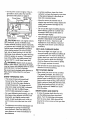
3 Horsepower
21 Inch Single Stage
Auger Propelled
SNOW THROWER
Optional
Electric Start
MODEL NO.
536.884561
Caution:
Read and follow all Safety
Rules and Operating
Instructionsbefore first use
of this product.
SEARS, ROEBUCK
340847 05/07/96
AND CO., Hoffman Estates 60179 U.S.A.
Tableof Contents
Warranty
Safety Rules
ContentsofShippingCarton
Assembly
Operation
Maintenance
LIMITED
ONE-YEAR
2
2
2-4
4
ServiceandAdjustments
Storage
Troubleshooting
EdgerRepairParts
5
6-9
!0-11
WARRANTY
Engine Repair Parts
Spanish(EspaSol)
Parts Ordering/Service
ON CRAFTSMAN
SNOW
11-15
15
16
17-22
23-26
27_42
Back Covm:
THROWER
For one year from the date of purchase, when this Craftsman Snow Thrower is maintained, lubricated, and tuned up according to the operating and maintenance instructions in the owner's manual, Sears will repair, free of charge, any defect in material or
workmanship.
If this Craftsman Snow Thrower is used for commercial or rental purposes, this warranty applies for only g0 days from the date of purchase.
This warranty
does not cover the following:
• items which become worn during normal use, such as spark plugs, drive belts and
shear pins.
• Repairs necessary because of operator abuse or negligence, including bent crank
shafts and the failure to maintain the equipment according to the instructions contained in the owner's manual.
WARRANTY SERVICE IS AVAILABLE BY RETURNING THE CRAFTSMAN SNOW
THROWER TO THE NEAREST SEARS SERVICE CENTER/DEPARTMENT
IN THE
UNITED STATES. THIS WARRANTY APPLIES ONLY WHILE THIS PRODUCT IS IN
USE IN THE UNITED STATES.
This warranty gives you specific legal rights, and you may also have other rights which
may vary from state to state.
Sears, Roebuck and Co.
Hoffman Estates, IL 60179
Look for this symbol to point out Important safety precautions.
ATTENTION!!!
Become alert!!! Your Safe,ty is Involved.
_
CAUTION: Always turn key to OFF
position and remove key to prevent
accidental starting when setting-up,
transporting, adjusting or making repairs.
IMPORTANT: Safety standards require
operator presence controls to minimize the
risk of injury. Your snow thrower is
equipped with such controls. Do not attempt
to defeat the function of the operator
presence control under any circumstances.
BEFORE
USE
• Read the owner's manual carefully. Be
thoroughly familiar with tlhe controls and
the proper use of the snow thrower. Know
how to stop the snow thrower and
disengage the controls quickly.
• Do not operate the snow thrower without
wearingadequateoutergarments.Wear
It means---
footwear that will improve footing on
slippery surfaces.
° Keep the area of operation clear of all
persons, particularly small children and
pets°
• Thoroughly inspect the area where the
snow thrower is to be used and remove
all foreign objects.
• Use extension cords and receptacles as
specified by the manufacturer for all snow
throwers with electric drive motors or with
factory-installed or optional starting
motors.
• Use only attachments and accessories
approved by the manufacturer of the
snow thrower (such as electdc starter kits,
etc.),
• Never operate the snow thrower without
good visibility or light. Always be sure of
your footing, and keep a firm hold on the
handles. Walk; never run.
, This snow thrower is for use on sidewalks, driveways, and other ground level
surfaces. CAUTION: should be exercised
while using on steep sloping st_rfaceso DO
NOT USE SNOW THROWER ON
SURFACES ABOVE GROUND LEVEL
such as roofs of residences, garages,
porches or other such structures or
buildings,
• Check all bolts at frequent intervals for
proper tightness to be sure the snow
thrower is in safe working condition.
• Disengage clutch before starting the
engine.
• Let engine and snow thrower adjust to
outdoor temperatures before starting to
clear snow.
FUEL SAFETY
• Handle fuel with care_ it is highly flam_
mable.
• Use an approved container.
• Check fuel supply before each use,
allowing space for expansion as the heat
of the engine and/or sun can cause fuel to
expand.
° Fill fuel tank outdoors with extreme care.
Never fill fuel tank indoors. Replace fuel
tank cap securely and wipe up spilled
fuel.
• Never remove the fuel tank cap or add
fuel to a running or hot engine.
• Never store fuel or snow thrower withfuel
in the tank inside a building where fumes
may reach an open flame.
OPERATING SAFETY
• Never allow children or young teenagers
to operate the snow thrower. Keep them
away whi_e it is operating_ Never allow
adults to operate the snow thrower
without proper instruction.
• Do not operate this machine if you are
taking drugs or other medication which
can cause drowsiness or affect your
ability to operate this machine.
• Do not use this machine if you are
mentally or physically unabl e to operate
this machine safely.
, Always wear safety glasses or eye
shields during operation or while performing an adjustment or repair to protect
your eyes from foreign objects that may
be thrown from the snow thrower.
• Do not put hands or feet near or under
rotating parts. Keep Clear ofthe discharge
,
•
,
-
,
•
opening at all times.
Exercise extreme caution to avoid slipping
or falling, especially when operating in
reverse or backing up.
Do not clear snow across the face of
slopes. Excercise caultion when changing
direction on slopes. Do not attempt to
clear steep slopes.
Never operate the snow thrower without
proper guards, plates, or other safety
protective devices in place.
Never operate the snow thrower near
glass enclosures, automobiles, window
wells, drop-offs, and the like without
proper adjustment of the snow discharge
angle. Keep children and pets away.
Never operate the snow thrower at high
transport speeds on slippery surfaces°
Look behind and use care when backing.
Never direct discharge at bystanders or
allow anyone in front of the snow thrower.
Do not run the engine indoors, except
when starting the engine and for transporting the snow thrower in or Out of the
building° Open the outside doors; exhaust
fumes are dangerous, containing CARBON MONOXIDE, an ODORLESS and
DEADLY GAS.
• Take all possible precautions when
leaving the snow thrower unattended
Disengage the auger/impeller, stop
engine, and remove key.
• Do not overload the machine capacity by
attempting to clear snow at too fast a rate
SAFE STORAGE
• Always refer to the owner's manual
instructions for !mportant details if the
snow thrower iS to be stored for an
extended period.
• Disengage power to the auger/impeller
when snow thrower is transported or not
in use.
• Never store the snow thrower with fuel in
the fuel tank inside a building where
ignition sources are present such as water
and space heaters, clothes dryers, and
the like. Allow the engine to coot before
storing in any enclosure.
REPAIR/ADJUSTMENTS
SAFETY
• After striking a foreign object, stop the
engine (motor). Turn key to OFF position
and remove key to prevent accidental
starting. Thoroughly inspect the
snowthrower for any damage, and repair
the damage before restarting and
operating it.
• If snowthrowershouldstartto vibrate
abnormally,
stopengine(motor)and
checkimmediately
for thecause.
Vibrationisgenerallya warning of
trouble°
• Stop the engine (motor) whenever you
leave the operating position_ Also, turn
key to OFF position and remove key
before unclogging the auger/impeller
housing or discharge chute, and when
making any repairs, adjustments, or
inspections, Remove wire from spark
plug to prevent accidental starting.
• When cleaning, repairing, or inspecting,
make certain the augedimpeller and all
moving parts have stopped.Turn key to
OFF position and remove key to prevent
accidental starting.
, Never attempt to make any adjustments
while the engine is running except when
specifically recommended by the
manufacturer.
• Maintain or replace safety and instruction
labels, as necessary.
o Run the snow thrower a few minutes after
throwing snow to prevent freeze-up of the
auger/impeller,
WARNING'.
The engine exhaust
from this product contains chemicaEs
known to the State of California to cause
cancer, birth defects or other reproductive
harm.
Z_ WARNING:
This unit is equipped with
an internal combustion engine and should
not be used on or near any unimproved forest,-covered, brush-covered or grass-covered land unless the engine's exhaust system is equipped with a spark arrester meeting applicable local or state laws (if any). if a
spark arrester is used, it should be maintained in effective working order by the operatoro
In the state of California the spark arrester is
required by law (Section 4442 of the Califor-,
nia Public Resources Code). Other states
may have similar lawso Federal laws apply
on federal lands A spark arrester/muffler is
available through your nearest Sears Authorized Service Center (See ENGINE REPAIR
PARTS section in this manual).
•_
_
,..'_k%
b_-_t_%¢
"_
. .z,S_:_2.:_i.#x_....................
_
,.4
Contents of Parts Bag
I - Owner's Manual (not shown)
1 - Parts Bag (not shown)
t - 3.2 ounce container
Craftsman 2-cycle oil
Z._CAUTION:
Always wear safety
glasses or eye shields while assembling
snow thrower.
TOOLS
REQUIRED
Auger Control
Chute Control
FOR ASSEMBLY
Tee
1 - Knife to cut carton
Chute Deflector
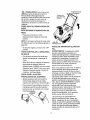
The figure to the right shows the snow
thrower completely assembled_
References to the right or left hand side
of the snow thrower are from the viewpoint
of the operator's position behind the uniL
TO REMOVE
SNOW
FROM CARTON
THROWER
, Locate and remove container of Craftsman 2-cycle oil.
, Remove the inserts positioned around the
unit and the packing material
, Cut down all four corners of the carton
and lay the panels flat,
• Pull snow thrower out of the carton.
TO ASSEMBLE
THROWER
THE SNOW
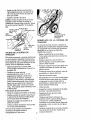
, Remove wrap on upper handle and along
the side of both handles. Discard wrap.
• Loosen the tee knobs on each side of the
J"
CHECKLIST
Before you operate your new snow thrower,
to ensure that you receive the best performance and satisfaction from this quality
product, please review the following
checklist:
J
All assembly
completed.
instructions have been
4"
The discharge chute rotates freely.
J
No remaining
upper handle. See figure on this page.
, Raise the upper handle to the operating
position as shown in figure: Hold upper
handle apart to prevent scratching lower
handle,
• Check to be sure the clutch cable is not
caught in the handle. Tighten the tee
knobs.
loose pads in carton
While learning how to use your snow
thrower, pay extra attention to the following
important items:
J'/
Make sure gas 'tank is fiIled with the
correct mixture of gasoline and oilo
4"/Become
familiar with all controls-their
location and function. Operate controls
before starting engine
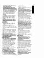
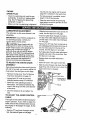
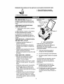
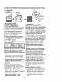
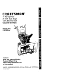
KNOW YOUR SNOW THROWER
READ THIS OWNER'S MANUAL AND SAFETY RULES BEFORE OPERATING YOUR
SNOW THROWER. Compare the illustrations with your SNOW THROWER to familiarize
yourself with the locationof various controlsand adjustments,Save this manual for future
reference.
NO
tgnition Off
40:1
Oil/Fuel Mixture
Ignition On
Primer Button
Auger Control Bar
Handle
Chute Control Rod
Chute
Lower
Recoil Starter
Handle
Chute
VIEW FROM
REAR
Control
AugerA;
Swit,lh Box
_Auger Housing
Auger Control Bar - Starts and stops the
auger which propels the snow thrower,
Chute Control Rod - Changes the direction of snow discharge.
Chute Deflector - Changes the distance
the snow is thrown.
Discharge Chute - Changes the direction
the snow is thrown.
Ignition Switch Key - Must be inserted
and turned to the ON position to start the
engine,
Choke Control - Used to start a coid engine,
Primer Button -injects fuel directly into the
carburetor manifold for fast starts in cold
weather.
Recoil Starter Handle
manually_
- Starts the engine
HOW
TO USE YOUR
SNOW
THROWER
TO STOP YOUR SNOW THROWER
- To stop the auge_'_ release the auger
control bar.
NOTE: If the auger continues to creep, refer
(To Adjust Auger Control Gable paragraph on
page ! i).
° To stop the engine, turn key to the OFF
position.
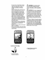
TO CONTROL
SNOW
DISCHARGE
° Turn the chute control rod to set the
direction of the snow throwing.
• Loosen the wing knob on the chute
deflector and move the deflector"to set
the distance. Move the deflector (UP) for
more distance, (DOWN) for less distance,.
Then tighten the wing knob (See figure
betow)o
Knob
Z_
CAUTION:
Read owner's manual
before operating machine. Never direct
discharge toward bystanders. Release the
auger control bar and stop the engine
before unclogging discharge chute or auger
housing and before leaving the machine,
BEFORE
WARNING:
STARTING
ENGINE
Experience
indicates that
alcohol blended fuels (called gasohot or
those using ethanol or methanol) can
attract moisture which leads to separation
and formation of acids during storage,
Acidic gas can damage the fuel system of
a n engine while in storage° To avoid engine
problems, the fuel system should be
emptied before storage for 30 days or
longer. Start engine and let it run until fuel
lines and carburetor are empty,. Use
carburetor bowl drain to empty residual
gasoline from float chamber (See figure in
Storage section, page 15). Use fresh fuel
next season.= (See Storage Instructions on
page 15 for additional information).
Never use engine or carburetor cleaner
products in the fuel tank or permanent
damage may occur.
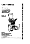
FILL
TO USE
AUGER
PROPEL
ACTION
• Squeeze the auger control bar down
against the upper handle to allow the
auger to turn.
• To propel forward, raise the handle to
allow the rubber auger blades 1o contact
the ground (See figure below).
Normal
GAS
The two cycle engine used on this snow
thrower requires a mixture of gasoline and
oil for lubrication of the bearings and other
moving parts. The correct fuel mixture ratio
is 40:1 (3.2 oz. oil per gallon of gas - see
Fuel Mixture Chart)., Gasoline and oil must
be pre-mixed in a clean gasoline container.
Always use fresh, clean, unleaded gasoline.
FUEL MIX CHART (Mixture
Auger Propelled
Position
U.S.
GAS
OIL
40:1)
IMPERIAL
S.I. (METRIC)
GAS
GAS
OIL
OIL
1 Gel 3.2 oz, 1 Gel 3.7oz_ 4 Lffers tO0ML
GASOLINE
AND
OIL MIXTURE
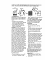
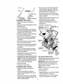
Mix gasoline and oil as follows:
• Pour 1 U.S. quart of fresh, clean,
unleaded automotive gasoline to a gallon
gasoline container.
o Add 3.2 oz of clean, high quality,
Craftsman two-cycle oil into the gasotine
container (One 3.2 ounces of oil provided).
DO NOT FILL THE FUEL TANK WITH GASOLINE THAT DOES NOT HAVE OIL MIXED IN IT.
SHAKE THE GASOLINE CONTAINER BEFORE EACH FILLING OF THE FUEL TANK.
Oil
(I/2 cup or 3,2 oz.)
Gasoline
!
(1 u.s.
!
Shake Can
+
1 UoS,gallon container
IMPORTANT:
Do not use outboard motor
oil or automobile
oils, such as SAE 30 oil,
or multi-viscosity
1oW-40.
oits, such as 10W-30 or
container and shake conlainer vigorously
so the oil mixes with the gasoline
° Add an additional 3 U.S. quarts of
gasoline to the gallon container and
shake the container again.
Gasoline is flammable
and
caution must be used when handling or
storing it. Do not fill fuel tank while snow
thrower is running, hot, or when snow
thrower is in an enclosed area. Keep away
from open flame, electrical spark, and do
not smoke while filling the fuel tank. Never
fill fuel tank completely; but fill the tank to
within 1/4-1/2 inch from the top to provide
space for expansion of tuel. Always flit fuel
tank outdoors and use a funnel or spout to
prevent spilling. Make sure to wipe up any
spilled fuel before starting the engine. Store
gasoline in a clean, approved container,
and keep the cap in place on the container.
Keep gasoline in a cool, well ventilated
place; never in the house. Never buy more
than a 30 day supply of gasoline to ensure
volatility° Gasoline is intended 1o be used as
a fuel for internal combustion engines;
therefore, do not use gasoline for any other
purpose. Since many children like the small
of gasoline, keep it out of their reach
because the fumes are dangerous to
inhale, as well as being explosive.
TO STOP
TO START
ENGINE
(RECOIL
START)
Before starting the engine, be certain that
you have read and understood all the
• Reinstall the cap on the gasoline
WARNING:
place. The engine will not start without the
key. See figure on next page.
ENGINE
• To stop the engine, turn the key to OFF
and remove key. Keep key in a safe
instructions on the preceding pages.
COLD START
Insert the key and turn ON.
Move the choke control to the FULL
position.
Push the primer button while covering the
vent holes as follows: (Remove finger
from primer button between primes).
Do not prime if temperature
50°F.
is above
Two times if temperature is 50 ° F to t5°F.
Four times if temperature is below 15°Fo
• Pull the starter handle with a smooth rapid
movement. Do not allow the starter rope
to snap back. Rewind smoothly while
holding the starter handle. If the engine
fires but does not start, pull the starter
handle until the engine starts_
• After three pulls, repeat the priming and
pulling steps again.
• As the engine warms up and begins to
operate evenly, move the choke control
slowly to the OFF position. If the engine
falters, return to i/2 choke until it runs
smoothly, then move to OFF position.
NOTE: Allow engine to warm up for a few
minutes before using snow thrower, as the
engine will not develop full power until it
reaches operating temperature_
WARM START
o Be sure the choke is in the OFF poSition and pull the siarter handle until the
engine starts.
Do notprimea warmengine,tfthe enginefailsto start,followtheColdEngineStartinstructions
on page8.
.l_,"
Primer Button
....
_'a_
Recoil Starter
I Vent Ho|e Handte
t /
_; -"-Key
CAUTION
Box
Never run engine indoors
or in enclosed, poorly ventilated areas.
Engine exhaust contains carbon monoxide,
an odorless and a deadly gas. Always stand
behind snow thrower(operator's position)
when starting engine. Do not put hands,
feet, hair or loose clothing in or near the
discharge chute deflector or auger housing
while the engine is running. The temperature of the muffler and neaby areas may
exceed 150 _ F.; avoid these areas also.
Z_
WARNING:
, Keep the area to be cleared free of
stones, toys and other foreign objects for
safety and to prevent damage to the
snow thrower.
, Do not use the auger propelling feature
when cleating gravel or crushed rock
driveways. Move the handle down to
raise the auger slightly.
ChOke'
./_
• In windy conditions, lower the chute
deflector to direct discharged snow close
to the ground where it is less likely to
blow into unwanted areas.
Objects such as gravel,
, The allowable forward speed of the snow
thrower is dependent on the depth and
weight of the snow. Experience will
establish the most effective method of
using the snow thrower under different
conditions.
DRY AND AVERAGE
SNOW
• Snow up to eight inch depth can be
removed rapidly and easily by walking at
a moderate rate. For snow or drifts of a
greater depth you may find it desirable 1o
slow your.pace to allow the discharge
chute to dispose of the snow as rapidly
as the auger receives the snow_
rocks or other debris, if struck by the auger,
may be thrown with sufficient force to cause
personal injury or property damager
• Plan to have the snow discharged
direction the wind is blowing.
We recommend standard safety glasses or
Wide Vision Safety Mask for over your
glasses.
WET
SNow
THROWING
TIPS
, This snow thrower will propel itself
forward when the handle is raised
enough tO cause the auger blades to
contact the ground, The auger should
stop when auger control bar is released.
tf it does not, refer to Adjust Auger
Control Cable paragraph on page 11.
• For most efficient snow throwing, turn the
discharge chute deflector to throw snow
downwind, and slightly overlap each
swath, in light snow take up to a full cut
and in heavy snow take less than a full
cut.
The distance snow will be discharged can
be adjusted by moving the discharge
chute deflector. Raise the deflector for
more distance or lower the deflector for
less distance.
PACKED
in the
SNOW
• Move slowly into snow of this condition.
The greater the depth, the slower you
should go. When it appears that the wet,
packed snow is causing the auger to slow
down and the chute to clog, back off and
begin a series of short jobs into the snow.
These short back and forth, 4 to 6 inch,
jabbing motions will "belch" the snow
from the chute.
SNOW
BANKS
AND
DRIFTS
• In snow of greater depth than the unit,
use the jabbing technique described
above. Turn the discharge chute away
from the snow bank. More time wil! be
required to remove snow of this type than
level snow.
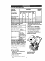
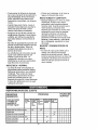
CUSTOMER
RESPONSIBILITIES
iii
_ _11,1,,11,,i,,
,...........
SERVICE
DATES
SCHEDULE
SERVICE
RECORDS
Fill In dates as
you complete
regular service
Before
After
Each
flint 12
Uae
Hours
As
Needed
v"
Tighten All Screws & Nuts
Before
Storage
segi.
Each
Season
_'
Check Spark Piug
Check Drive Belts
LubricateChute ControlFlange
Check Fuel
......
_,,,,
=
•
.
= __
Drain Fuel
PRODUCT
SPECIFICATIONS
HORSE POWER:
3HP
DISPLACEMENT:
6.0 cue in.
• Remove all snow and slush from the
snow thrower to prevent freezing of auger
or controls.
LUBRICATION
- AS REQUIRED
• Lubricate the flange on the discharge
GASOLINE
CAPACITY:
chute befor e storage. See To Remove
Top Cover instructions on page 12.
t quart
(unleaded)
• See Lubrication Chart diagram for
=UEL/OIL MIX RATIO: 40:1
lubrication points and type of lubricant.
(32 oz. of aircooled engine 2
cycle oi! specified
for 40:1 per 1 gal. of
gas)
SPARK PLUG:
•
GENERAL
LU BRICATION
CHART
Champion RCJSY
(Gap .030) or
EQuivalent
......
RECOMMENDATIONS
The warranty on this snow thrower does not
cover items that have been Subjected to operator abuse or negligence. To receive full
value from the warranty, the operator must
maintain the snow thrower as instructed in
this manual. The above chart is provided Io
assist the operator in properly maintaining
the snow thrower.
SNOW
AFTER
THROWER
FIRST
USE
• Check for any loose or damaged parts
after each use_
e,,
Coatflangewith adingfng type
grease such as Lubriplatel
• Tighten any loose fasteners.
AFTER
EACH
USE
• Run the machine to clear the auger of
snow.
lO
ENGINE
SPARK
securely into the engine and the spark
plug wire is attached to the spark plugo
PLUG
If a torque wrench is available, torque
plug to 18 to 23 foot pounds.
- Clean the spark plug and reset the gap
periodically. To service or replace spark
plugo See To Replace the Spark Plug
paragraph on page i4.
Clean the area around the spark plug
base before removal to prevent dirt from
entering the engine
• Make sure that the spark plug is tightened
CARBURETOR
The carburetor
ADJUSTMENT
• Slide the boot toward the loose end of the
on this snow thrower is not
cable. See first figure on next page,
adjustable.
IMPORTANT: If you think the carburetor
not operating properly, contact your
nearest Sears service center,
, Push the cable down through the hole in
the top of the cable adjustment bracket to
provide slack in the cable. See first figure
is
on next page.
• Remove the "Z" hook from the top hole in
the cableadjustment bracket and move to
the next hole away from the top of the
bracket. See first figure on next page.
Z_ CAUTION: Never tamper with the
engine governor which is factory set for
proper engine speed. Over speeding the
engine may increase the danger of
personal injury and will void the engine
warranty. If you think the engine governor
high speed needs adjusting, contact your
nearest Sears service center who has the
proper equipment and experience to
make any unnecessary adjustments.
TO ADJUST
THE CHUTE
o Pull cable slack through cable adjustment
bracket and insert in the control bar_ See
first figure on next page.
• Replace boot over cable adjustment
bracket.
• insert "Z" hook in the auger control bar.
• Start the snow thrower and check that the
CRANK
ASSEMBLY
auger does not continue to turn when the
auger control bar is released.
tf you cannot rotate the chute crank fully to the
left and to the right, you need to adjust the
chute crank. See first figure on this page.
Adjustments
• Remove the top cover. See To Remove
Top Cover instructions on page 12,
NQtchin
Flange
tnch Nuts
_djustment Bracket
• Loosen both 1/2" nuts on the crank
adjusting bracket using 1/2" wrenches,
, Swivel the crank adjusting bracket to
allow about 1/8" clearance between the
'Worm
notch in the flange and the outer diameter
of the worm.
• Once this clearance is set, tighten the
nuts.
TO ADJUST THE AUGER CONTROL
Auger Control
Bar
CABLE
The auger control cable is set at the factor), for
proper operation, tf you need to adjust the
cable, because the control bar does not properly engage or disengage the auger, do the
following:
, Remove "Z" hook from the auger control
bar. See second figure on this page,
tl
Cable---_.._i
Cable AdJust- /
• Remove the two screws holding the belt
cover to the top cover. Use a large flat
head screwdriver, NOTE: If the top cover
is already removed, omit this step.
meo,
To,ii
• Remove the one screw holding the belt
cover to the bottom cover. Use a large flat
head screwdriver,
Z" Hook
• Grasp the bottom portion of the belt cover
and pull down and out to remove,
TO REMOVE
TOP COVER
, Using a large flathead screwdriver,
remove the heat shield from the rear of
the belt cover.
• Follow these steps from operator's
position.
o Remove the T-knob and fasteners on the
° Reinstall in reverse order.
Screws to be
Bolts to be
removed from Top
discharge chute,
• Remove the gas cap.
• Remove the two bolts and nuts from the
T_
front tip of the top cover. Use a flat head
screwdriver and a 3/8" wrench.
• Remove the bolt from the front right side,
Use a 5/I6" and 3/8" wrench,
• Remove the four screws on the left side
of the top cover. Use a large flat head
screwdriver°
Cover
Chute
• Remove the bolt from the front left Side.
Use a 5/16" and 3/8" wrench,
Shield
• Remove the four screws on the right side
of the top cover, Use a large flat head
screwdriver.
. Remove the three screws from the top
portion of the control panel Use a large
flat head screwdriver°
Fasteners
Lower ;hute
Bolts to
removed from
Belt Cover
. Carefully pull up on the rear of top cover
making sure to clear gas tank,
• Carefully lift top cover over the three bolts
holding the lower chute to the chute ring_
NOTE: This area was designed to have
a tight fit, it will be necessary to rock top
cover carefully over these bolts.
TO ADJUST BRAKE
PAD
The brake pad is adjusted at the factory and no
periodic adjustment is necessary°
IMPORTANT:
Adjustment should only be
made to the brake if the brake pad has
become loose or has been removed. To
• Remove lop cover.
. Reinstall in reverse order.
TO REMOVE
to be
removed
from Belt
Cover
adjust proceed as follows:
BELT COVER
NOTE:
• Follow these steps from operator's
position.
See figure on next page for proper
location of brake pad,
• Turn engine off,
• Using a large flathead screwdriver,
remove the heat shield from the rear of
the belt cover.
. Remove belt cover,, See To Remove Belt
Cover paragraph on this page,
• Remove the top cover See To Remove
Top Cover instructions on this page.
• Remove the four bolts and nuts holding
the belt cover to the auger housing, Use
a 5/16" and 3/8" wrench.
12
• Reinstall the belt cover_
NOTE: Make sure the belt is in proper
position, See To Replace the Drive Belt
paragraph on this page,
If the drive belt is damaged
excessively,
• Tie the control bail to the upper handle
with a piece of string, NOTE: This wil!
engage the pulley and belt system,
or worn
replace it with a new belt.
TO REPLACE
THE
DRIVE
BELT
The drive belt on this unit is of special
construction and must be replaced with the
same type belt available at your nearest
SEARS Service Center,
. Using a 7/16 wrench, 7/16 socket, and a
rachet loosen screw and nut on brake
pad. See figure below for location of
screw and nut°
• Remove the belt cover. See to Remove
the Belt Cover paragraph on page 12_
• Adjust brake pad up or down to have a
1/8" gap between the bottom of the brake
pad and the belt.
• Move belt guide away from belt. See first
figure on next page, BeSt may come out
without loosening belt guide. Carefully
press idler pulley down to release brake
pressure on bell
• Tighten screw and nut.
NOTE:
Check the drive belt adjustment
before re-installing the belt cover. See To
Adjust the Drive Belt paragraph below,
Screw and nut to
be loosened
• Remove belt from between brake pad
and roller.
Idler Pulley
• Remove old belto
e Pulley
• Replace with new belt by carefully
pressing down on the idler pulley and
placing the belt between the brake pad
and roller with belt ribs down,
BrakePad
• Release belt pulley,
• Attach new bet! to the engine pulley and
auger pulley,
° Make sure the belt is seated ProPerly,
TO ADJUST
• Move belt guide into position,, The belt
guide should be 3/32" from belt when belt
THE DRIVE BELT
is engaged as shown in second figure,
page 14.
If the engine drive pulley and the auger
drive pulley are not alignedproperly,
excessive belt wear willoccur_To check the
, Check the drive belt adjustment, See to
Adjust the Drive Belt paragraph above,
• Reinstall belt cover,
pulley alignment, proceed as follows:
• Remove belt cover° See To Remove Belt
Cover on page 12,
, Place a straight edge approximately 16"
long across the large auger pulley,
touching two points and extending to the
engine pulley. See next figure, The
outside of the engine pulley must be flush
with the straight edge, If the pulleys are
aligned, skip to the last step.
To adjust the engine pulley:
• Loosen the 2 set screws on the engine
pulley,
• Slide the engine pulley in or out on the
shaft until the pulley is flush with the
straight edge.
)lace straight
ed[_eat these
poEnts.
• Tighten the 2 set screws on the engine
pulley,
t3
• Slide the auger assembly out of the
bearing assembly on the right side of the
snow thrower.
• Tip the auger assembly enough to allow it
to slide out of the auger housing.
,
Guide
Install the new auger assembly in reverse
'order of removal.
NOTE: Check the drive belt adjustment
before reinstalling the belt cover (See To
Adjust the Drive Belt paragraph on page
13).
Relier
TO REPLACE THE SPARK PLUG
The spark plug is housed in the engine
compartment under the top cover (See
figure below) and cannot be seen under
normal conditions.
_dve
Belt
idler PL ley
En
Remove
Pulley
o
m
bottom
cover.
To remove
proceed:
Stand the unit onto it's front end,
Using a flathead screwdriver remove the
ten screws. See figure below.
Remove four screws on right hand side of unit
Remove these
screws from top
Guide
TO REPLACE
THE
AUGER
• Remove the belt cover, see To Remove
Belt Cover paragraph on page 12 and the
drive bell See the Drive Belt Replacement paragraph on page 13.
• Remove the auger pulley, see figure
below from the auger shaft (threads are
left hand; turn clockwise to remove). Place
a piece of wood (2x4) on the center
paddle area to secure auger to keep from
turning.
Remove t _ese screws
Irom left side
, Remove the bearing assembly from the
left frame of snow thrower by removing
the two nuts. See figure below°
Bottom Cover
• Remove bottom cover°
• The spark plug and wire are now visible.
• Remove the spark plug wire.
• Clean the area around the plug base to
prevent dirt from entering the engine
when the plug is removed°
• Remove the spark plug. tf it is cracked,
fouled or dirty, it must be replaced. See
page 10 for the proper replacement plug.
• Set the gap between the electrodes of the
new spark plug at o030 inch° Next, install
the spark plug in the cylinder head.
Beadng
Left
Au
Pulley
14
• Torque plug to 18 to 20 It, lb. tf you do not
use a torque wrench, tighten the plug
firmly (See next figure).
recommend
that such work should be done
by technicians trained to work on snow
thrower type engines, Take your snow
thrower to your nearest SEARS Service
Center for repair and adjustment.
ADJUST
o Pushthesparkplug'wireontothe spark
plug.
• Reinstallthetop cover.
ENGINE
SERVICE
WARNING:
SPEED
Your engine speed has been factory set. Do
not attempt to change engine speed or it may
result in personal injury. If you believe that
the engine is running too fast or too slow, take
your snow thrower to your nearest SEARS
Service Center for repair and adjustment.
Unless the operator is fully qualified to
make engine repairs or adjustments, we
Z_
ENGINE
Never store your snow
carburetor by pressing upward on bowl
drain located on the bottom of carburetor°
thrower indoors or in an enclosed, poorly
ventilated area_ if gaso!ine remains in the
tank, fumes may reach an open flame,
spark or pilot light from a furnace, water
heater, clothes dryer, cigarette, etc.
See next figure.
Carburetor
To prevent engine damage (if snow thrower
is not used for more than 30 days) follow
the steps below.
SNOW
THROWER
STORAGE
- Thoroughly clean the snow thrower.
Bowl Drain
• Lubricate all the lubrication points. See
the Maintenance section, page 10.
o If you do not want to remove gasoline, a
fuel stabilizer (such as Craftsman fuel
• Be sure that all nuts, bolts and screws are
securely fastened. Inspect all visible
moving parts for damage, breakage and
wear. Replace if necessary.
stabilizer No. 33500) may be added to
any gasoline left in the tank to minimize
gum deposits and acids° If the tank is
almost empty, mix stabilizer with fresh
• Touch up all rusted or chipped paint
surfaces; sand lightly before painting
gasoline in a separate container and add
some to the tank. Always follow instructions on stabilizer container. Instructions
. Cover the bare metal parts of the blower
housing and auger with rust preventative,
such as a spray lubricanL
ENGINE
Gasoline
Right side view of
engine
on stabilizer container. Then run engine
at least 10 minutes after stabilizer is
added to allow mixture to reach carbure-
STORAGE
must be removed or treated to
tor. Store snow thrower in a safe place.
See Warning under STORAGE.
prevent
gum deposits from forming in the
tank, filter, hose, and carburetor during
storage. Also during storage,
alcohol
OTHER
° If possible, store your snow thrower
indoors with the gas removed and cover it
blended gasoline that uses ethanol or
methanol (sometimes called gasohol)
attracts water° It acts on the gasoline to
form acids which damage the engine.
to give protection from dust and dirt
• If the machine must be stored outdoors,
• To remove gasoline, run the engine until
the tank is empty and the engine stops_
Then drain remaining gasoline from
block up the snow thrower to be sure the
entire machine is off the ground.
t5
L
Cover the snow thrower with a suitable
NOTE:
A yearly checkup or tune-up at a
SEARS Service Center is a good way of
ensuring that your snow thrower wilt
provide maximum performance for the next
protective cover that does not retain
moisture. Do not use plastic or vinyl,
season,,
TROUBLE
CAUSE
CORRECTION
i Dlfftcult starting
Defective spark plug
Replace defective plug
Engine
Unit running on CHOKE
Move choke lever to OFF positor
stalls
Engine runs
erractically
or
Blocked fuel line or low on fuel
Clean fuel line; check fue! supply; add fresh gasoline (gasoline/oil mixture if 2-cycle engine)
Water or dirt in fuel system
Use carburetor bowl drain to
flush and refill with fresh fuel
Carburetor out of adjustment
See carburetor adjustment
tion in this manual
Loss of power
Excessive
vibration
Units fails to
_ropel itself
Loose parts; damaged
Stop engine immediately and
turn key to OFF position and remove key. Tighten all bolts and
make all necessary repairs, tf vibration continues, have the unit
serviced by a Sears service repairman
Damaged auger
Repair or replace auger assem-
Drive belt loose or damaged
Replace drive belt
Incorrect adjustment
trol cable
Unit fails to
discharge snow
impeller
sec-
of auger con-
Adjust auger control cable
Auger drive belt loose or damaged
Adjust auger drive belt; replace if
damaged
Auger control cable not adjusted
correctly
Adjust auger control cable
Stop engine immediately and tur_
key to OFF position and remove
key. Crean discharge chute and
inside of auger housing
Discharge chute clogged
Foreign object lodged in auger
16
Stop engine immediately and tur_
key to OFF position and remove
key, Remove object from auger.
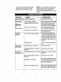
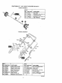
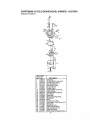
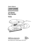
CRAFTSMAN
2'1" - 3HOP. SNOW THROWER
536.884561
ENGINE/DRIVE AS£EMBLY
0
2
1
42
75
33431OB
Note: Always use original equipment
parts. Use o! service/replacement parts
other than originat paris may void your
warranty,
REF.
NO. PART NO.
10
ENGINE
11
12
20
21
22
23
24
25
26
27
28
30
31
32
33
40
180077
120638
333970
180077
120838
180018
t502
313440
120393
120638
180079
313444
333594
1498
313473
320077
PART NAME
Engine, Model 143 973091
(See Engine pages)
Screw, 5/16-18x 75
Washer, Hvsptik
Brake Pad
Screw, 5/164 8x 75
Washer, Hvsptlk
Screw, 114-20x.82
Nut, 1/4-20 Reghexctr{k
Belt Guide
Fiatwasher 344x 69x..065
Washer, Hvsptik
Screw, 5/16-18x 1.00
idler Pivot Arm
Shoulder Bolt, 5116-18
Nut, 5/16-18 Reghexctrlk
Extension Spring
Idler Arm
A|i unnumbered items are
interchangeable with opposite
side
'REF:
NO,, PART NO,
41 333594
1496
42
45
48924
46 i302637
47 _41529
50
180034
51
120392
52
313443
53 Lt5o2
60 !313436
61
414106
62
121223
70
48921
71 12125
72
191956
75 319598
340847
PART NAME
Shoulder Bolt, 5/16-18
Nut, 5/16-18 Reghexctrik
Idler Pulley
Screw, 3/8-16xl .50
Nut, 3/8-16Hexjam
Screw, I/4-20xl .50 In_
Flatwasher, .28_x.63x .085
Roller, Belt Pinch
Nut, 1/4-20 Reghexctrlk
Rod, Clutch Linkage
Flatwasher, 188x38x 040
Cotter Pin .O62x.75
Engine Put]ey
Woodruff Key
Screw, t/4-20x 386qsetcp
Belt, Poly V
Owner's Manual Eng/Sp
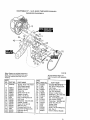
CRAFTSMAN 21"- 3H.P, SNOW THROWER
FRAME ASSEMBLY
REF.
NO. PART NO.
@
80
81
90
9t
92
100
101
102
107
108
109
110
112
113
t14
115
116
117
118
333769-853
333767
333987
160044
t502
333749-853
18OO2O
1502
180020
120392
1502
333739
340300
323363
47345
335351
323387
56679
335906
536.884561
PART NAME
Frame, Side LH
Channel, Frame Support
Screw, 1/4-20x2.00
Nut, t14-20 Reghexctrlk
Bracket, Fuel Tank 1.5 Qt
Screw, 1/4-20xo75
Nut, 1/4-20 Reghexotrlk
Screw, 1/4-20x.75
Flatwasher. 281x .63x.065
Nut, 1/4-20 Reghexctrlk
Fuel Tank 1.5 QI.
Fuel Cap 40:1
Gas Tubing 8 Inches
Hose Clamp
Plate, Bolting Support
Hose Clamp
Filter, In-Line
Tubing, 6 inches
333966E
REF,
NO, PART NO,
120
121
124
125
126
127
128
!30
131
140
141
I42
143
145
146
t47
.,
t8
_
u,
340088
56021
578109
334298-853
180024
120392
1502
57587
333643
56992
138557
48140
49643
154601
335507
271172
PART NAME
Bottom Cover
Screw, 1/4-14x.75 Slwatap
Nut, 1/4-20 Speed J Type
Panel, Control
Screw, 1/4-20xl .25
FlatwaSher .2811x..63x_065
Nut, t/4-20 Reghexctrlk
Grommet & Washer
Knob, Stand Tee
Switch, Ignition
Washer, Regintlk
Nut, 5/8-32, tgn_Switch
2 Keys & Ring Assy
Primer, Enginer
HOse,Primer 950Lg
Nut, 1/4-20 Reghexkeps
339988E
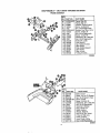
CRAFTSMAN
21" - 3H.P. SNOW THROWER
536.884561
BELT COVER ASSEMBLY
3343_ 1 i
REF.I
NO. IPART NO, i PART NAM E
170 340087
Cover, Top
171 274707
Screw, 10-24x 5Wahhma
172 997316
Nut, #10-24 Reghexctrik
173 56021 _
Screw, I/4-14x.75 Slwatap
!74 5538O
Seal, Strip Aug Chute Foa{
176 578109
Nut, 1/4-10 Speed J Type
181 56021
Screw, 1/4.14x75 Stwatap
t82 578t09
Nut, 1/4-10 Speed J Type
REF.!
NO, PARTNO.
150
151
152
157
159
160
161
162
340089
274707
997316
56021
578109
335855-853
56021
578109
PART NAME
Belt Cover
'Screw 10-24x5 Wahhma
Nut, #10-24 Re hexctdk
Screw I/4q 4x.;
Iwatap
Nut, 1(4-10 Spe J Type
Heat Shield
,Screw, 114-14x. Stwatap
J
_e
Nut, 1/4-10 Spe
DISCHARGE CHUTE ASSEMBLY
REF.I
NO, ] PART NO.
580 I 333859
58! ! 300302
582 I 577021
583 I 337166
590 1 334234
591 l 180016
592 I 46931
600 I 325847
601 ! 308931
602 i 302843
603 ! I203.93
604 I 13527
605 I 120376
606 ! 578088
607 t 120393
608 1 1498
PART NAME
Ring, Chute
Screw, #10x 50 Tap
Guide, Chute
Seal Strip
Lower Chute
Nut, 114-20 x,50
Nut, 1/4-20 Mac-lock
Upper Chute
Wii'e, Hinge
Bolt, 5!16-18x!.25 Oarr.
Ftatwasher .344xo69x 085
Knob, T
Nut, 5/!6-18 Reghex
Screw, 5t16-18x. 75
Flatwasher .344x.B9x.065
Nut, 5!t6-18 Reghexctrlk
337341A
t9
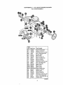
CRAFTSMAN
21" -,3H.P. SNOW THROWER
536.884561
BELT COVER ASSEMBLY
REFo
NO. i PART NO.
340091 ....
_80
_81
180020
_82
120392
_83
I502
_90
55323
577707
_,91
_,92
180020
493
46931
510
577023
511
!80021
512
120392
46931
5t3
520
327072
520-2 302565
520-6 49838
520-8 335992
520-1( 307049-853
529
580251
53O
49562
531
334287
532
180018
533
120392
534
t502
540
5457O
313670
541
PART NAME
Auger Housing Assy.
Screw, 114-20x75
F{atwasher,.28 tx 63x.065
Nut, 1/4-20 Reghexctrlk
Scraper Blade
Rivet, Ovset
Screw 1/4-20x_75
Nut, 1/4_20Mac-lock
Bearing, Flange
Screw 1/4-20x 88
Flat'washer .281x.63x 065
Nut, 1t4-20 Mac-Lock
Auger Assembly
Blade, Auger
Rivet, Ovset
B_ade,Center
Auger & Blade Assy
Retainer, Bearing
Bearing, Ball
Bearing Retainer
Screw 114-20x62
Flat'washer .281x..63x.065
Nut, 1/4-20 Reghexctrlk
Spacer, Sleve.640x88x_ 15
Pulley, Poly 6"
3339690
2O
CRAETSMAN
21" - 3H.P. SNOW THROWER
536°884561
WHEEL ASSEMBLY
REF.
4NO. PART NO.
"65o
65l
660
661
662
996416
577036
996416
577598
PARTNAME
Axle, Shaft
Flatwasher 391xl.00x.125
Tire & Rim 6x1.
FlatwashP.r .39tx I O0x,125
Ring, Retaining
335418B
HANDLE ASSEMBLY
75
REF
NO,
PART NO.
74o 313449
741
742
743
744
750
751
752
313441
313448
308146
313471
333909.,853
' 180024
120392
NO.
753
760
761
762
763
764
765
PART NAME
Cable, Upper Control
Bracket, Cable Adjust
Cabte, Lower Control
Boot, Clutch Spring
Spring, Extension
Lower Handle
Screw 1/4-20xl 25
Flatwasher. 281x.63x.065
PART NO.
1502
333919-853
333954_853
_11767
_2025
13527
120376
PART NAME
Nut, I/4-20 Reghexctrik
Upper Handle
Control Bail
Bolt, 5/16-18xl.75 CUH
Formed Washer
Knob, T 2BTade5/16-18 Nut
Nut, 5t16-1B Reghex
334312A
21
CRAFTSMAN
21" - 3H.P. SNOW THROWER
536.884561
DECALS
;REF'
No. IPARTNO.,
!822
824
826
828
829
830
831
835
CHUTECONTROLROD
874
402635
402896
69880
318494
308768
313892
70141
337524
PARTNAME
Decal, Dash
Decal, 3/21"
Decal, Warn Hot Muffler
Decal, Choke
Decal, Dang Stripe
Danger Chute Decal
Decal, Danger Auger
Decal, Auger Control Bar
ASSEMBLY
850
851
REF.
NO, PART NO.
850 3343i4
851 120394
852 121224
853 313431
854 335264
855 _120394
856 57082
857 i331532
858 i3809
REF:
I
PART NAME
NO,
859
860
861
870
871
872
873
874
Chute Rod Assembly
Ftatwasher,406x.81x.065
Cotter Pin ,,094xl.00
Washer, Curved Spring
Chute Crank Brkt Assy
Flatwasher .408x.81 x.065
Knob, Sleeve
Nut, Push
Cart. Bolt 114-20x.63
I PART NO.
120393
120638
120375
333946-853
70993
120393
120638
120376
PART NAME
Flatwasher_344x,69x,065
Washer, HvsplJk
Nut, I/4-20 Reghex
::
Chute Rotate Bramket
Carr, Bolt, 5/!6-18x.75
Flatwasher .344x.69x.065
Washer, Hvsptik
Nut, 5/16°18. Reghex
334313C
22
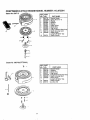
CRAFTSMAN
2,,CYCLE ENGINE MODEL NUMBER: 143.973091
Starter No. 590712
11
_2
13
--s
REF, PART
NO. NO.
O
590712
590599A
1
2
590600
3
590696
4
390601
590697
5
6
590698
590699
7
8
59o709
11 590713
590535
t2
13
590701
REF.
NO.
0
3
6
7
8
11
12
PART
NO.
590743
590740
590616
590617
590645A
590643
590535
PART NAME
Rewind Starter
:_aring
Pin (lnct, 4)
sher
Retainer
Washer
Brake Spring
Starter t_og
Dog Spring
Pul)ey & Rewind Sprg Assy
Starter Housing Assy
Starter Rope
(Length 98"x9/64" dia)
Starter Handle
Starter No. 590743(OPTIONAL)
t3 590701
14 1590741
t_
_1 _7
'23
PART NAME
Rewind Starter
Retainer
Starter Dog
Dog Spring
Pulley&Rewind Spring Assy
Starter Housing Assy
Starter Rope
(_Length98"x9t64" dia)
Starter Handle
Locking Tab
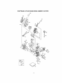
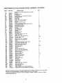
CRAFTSMAN
2-CYCLE
ENGINE
MODEL
NUMBER:
370A
lol
24
143.973091
CRAFTSMAN
REF.#
PART NO.
1
16B
19
24
29
29A
30
33A
34A
4I
42
43
45
46
69
69A
75
77
89A
90
92
93
100
101
103
! 19
120
131
135
163
169
172A
174
t77
184
186
187
216
257
258
260
261
274
275
277
285
287
325
330
350
351
36I
370A
380
390
395
400
490291A
570707
530110
530150
530104A
290607
570644
650579
310283A
310190
310167
310235B
650633
510292A
5t0323A
510319
530105
611032
611066
650815
650390
34443A
6t0118
651007
510274A
250240B
650477
611049
650838
510325A
570708
650579
650959
510326A
490322
570438A
570645
650911
350422
350437
650737
5 t 0207A
390330
650869
590551A
650926
29443
6i 1!64A
570629A
321800
650909
36261
632714
590712
88941
510324B
2-CYCLE
ENGINE
MODEL
NUMBER:
DESCRIPTION
143.973091
QTY.
Cylinder (Order SiB if replacement is needed)
Air Vane
Extension Spring
Bal! Bearing
Needle Bearing & Line (Set (37 Needles)
Cartridge Bearing
Crankshaft
Cover Plate
Screw, Torx T-25 10-24xl/2"
Piston & Pin Assy(inc143)
Ring Set
Piston Pin Retaining Hing
Connecting Rod Assy (lncl 29, 29A ,&46)
Connecting Rod Bolt
Cylinder Cover Gasket
Cover Plate Gasket
Oil Seat
Cartridge Bearing
Adapter Sleeve
Flywheel
Bellevitle Washer
Flywheel Nut
Solid Staleignition (Incl, t01)
Spark Plug Cover
.
Screw, Torx T-I5, 10-24x151t6
Cylinder Head Gasket
Cylinder Head
Screw, Torx T.30,114-20x314"
Resistor Spark Plug (RCJ8Y)
Washer
Compression Re_easeCover Gasket
Compression Release Cover
Screw, Torx T-25,10,_24xl/2"
Screw, 5/32 Allen 114-20x1"
Carburetor Gasket
Governor Link
Spacer
R.P,M. Adjusting Lever
Screw. Torx T-30, I14-20×5/8"
Blower Housing Base (lncl, 75)
Blower Housing
Screw 1/4-20x2-3/4"
Exhaust Gasket
Muffler (fnc1274&277)
Screw, t/4-20x2-314"
Starter Cup
Screw 8-32x21164"
Wire Clip
Ground Wire
Primer Assy
Primer Line
Screw Torx %30, I14-20x7/8"
Decal Lubrication
Carburetor (lncI 184)
Rewind Starter
Electric Starter Motor (120Volt) (Optional)
Gasket Set (tncl Items Marked PKin Notes)
!
1
t
1
t
I
1
1
4
1
2
2
1
4
1PK
1PK
2
1
1
1
t
t
1
!
2
1PK
!
5
1
1
1PK
1
I
2
2PK
I
1
1
4
1
1
4
1PK
1
2
1
3
1
1
1
1
2
1
1
1"
1
10
NOTE: This engine could habe been built with 590743 starter. Refer to the design of the rope pulley
strength ribs [or part identification. Individual starter parts do not interchange
0 Incl, (1) each of part #s 510207A. 510274A. 510292A, 510323A. 510325A. 510326A, 510346A,
and (2) of part #510110A
25
CRAFTSMAN
2-CYCLE ENGINE MODEL NUMBER:
Carburetor Noo6327 t4
'
32
I
4D"'l_
REF: PART .......
NO. NO.
0
I
2
4
5
6
7
10
14
15
16
25
26
27
28
29
30
31
32
33
40
44
48
632714
632166
632169
631184
631183
631621
650506
631300
631815
630735
632164
631949
632386
631024
632019
631028
631021
631022
27136A
27554
632385
631334
631027
PART NAME
Carburetor
Throttle Shaft & Lever Ass'y
Throttle Return Spring
Dust Seal Washer
Dust Seal (Throttle)
Throttle Shutter
Shutter Screw
Choke Shaft & Lever Assy
Choke Shutter
Choke Positioning Spring
Fuel Fitting
Float Bowl
Float Dampening Spring
Float Shaft
Float
Float Bowl "O" Ring
inlet Needte, Seat, Cfip (inci 31)
SpringClip
Bowl Drain Assy
Drain Plunger Gasket
High Speed Bowl Nut
Bowl Nut Washer
Welch Plug, Atmospheric Vent
26
143.973091
REMOVEDORA
DE NIEVE (Arranque
el_ctrico optional)
Tabla of Contenidos
27
Garantia
27
Regtas de Seguridad
27-29
Contenido del paquete con articulos 30
Montaje
30
Operation
31-35
Mantenimento
35-36
Servicio y Ajustes
Almacenamiento
Solucion de Problemas
Partes de Repuecto
Partes de Motor
Spanish(EspaSol)
Orden de Partes Servicio
GARANTIA LIM1TADA DE UNO ANOS SOBRE LA REMOVEDORA
CRAFTSMAN
36-41
41
42
17-22
23-26
27-42
Contratapa
DE NIEVE
Durante uno aSos a partir de la fecha de compra, cuando esta Removedora de nieve
Craftsman sea martenida, lubficada y afinada de acuerdo con tas instrucciones en el
manual det propietafio, SEARS reparar&, sin recargo alguno, cuafquier defecto en
materiales y mane de obra.
Si esta Removedora de nieve Craftsman se usa para prop6sitos comerciales o de
arrendamiento, esta garantfa es v_lida durante 90 dies a partir de la fecha de compra_
Esta garamt[a no cubre .lo siguiente:
• Elementos _ungibtes los cuales se gastan durante el uso normal, tales como buij[as,
correas de transmisi6n y claavijas de seguro por esfuerzo cortante.
• Reparaci0nes necesarias debido al abuso o negligencia de! operador, incluyendo
cigDef, ales dob]ados y la falta de mantenimiento del equipo de acuerdo con [as
instrucciones conten[das en el manua! del propietario.
EL SERVICIO DE GARANTIA SE PUEDE OBTENER AL DEVOLVER LA
REMOVEDORA
DE NIEVE CRAFTSMAN AL CENTRO/DEPARTAMENTO
DE
SERVICIO SEARS MAS CERCANO EN LOS ESTADOS UNIDOS. ESTA GARANTIA
ES VALIDA SOLO CUANDO ESTE PRODUCTO SEA USADO EN LOS ESTADOS
UN1DOSo
Esta garant[a Ie otorga derechos tegales espec[ficos, y asimismo es posibte que
tenga otros derechos los cuates varian de estado a estado.
Sears, Roebuck and Cox, D817WA, Hoffman Estates, IL 60179
Esto signlfica---ATENCtON!!!
Este!!! U seguridad esta de por medlo.
Busque este simbolo para destacar precauciones
de seguridad importantes.
PRECAUCtON: Si0mpre haga girar la
controles y el uso apropiado de la
!lave hacia la posici6n "APAGADO" (OFF) y
removeclora de nieve Sepa c6mo
retire la del en cendido para evitar un
detener la removedora de nieve y
arranque accidental al montar, transporter,
desenganchar los controles
ajustar o efectuar reparaciones_
r&pidamente
IMPORTANTE:
Los estandares de
2.
sugufidad requieren la presencia del
operador en los controles pare minimizer el
riesgo de heridas_ Su removerdora de nieve
esta equipada can dichos controfeso No
intente pasar pot alto la funci0n det control
de preseencia del operador bajo ninguna
circunstanciao
se encuentra en operaci6n, Nunca
permita que adultos operen la
removedora de n!eve sin instrucci6n
apropiada, No Ileve pasajeros,
3.
Mantenga e! &rea tibre de personas,
especiaimente niR0s pequef_os y
mascotas.
4..
Tenga precauci6n a fin de eviler
deslizamientos o caidas, especialmente
CAPACITACION
1.
Lea ei manual det operador
cuidadosamente.
Familiarfcese
completamente
Nunca permita a niRos operar ]a
removedora de nieve y mant6ngalos
tuera def alcance de la misma mientras
con los
27
aloperarla removedora
de nieveen
retroceSOo
PREPARACiON
I. _nspeccione
completamente
el_rea
dondese usar&la removedora
de
nievey retiretodaslasesteras,trineos,
tableros,alambres,y otrosobietos
extra5os
2. Desenganche
todoslosembragues
y
cambiea neutroantesde arrancarel
motor.
3.
4.
No opere ta removedora de nieve sin
vestir las prendas de invierno
adecuadas para ambientes exteriores..
Vista catzado que mejore su
estabilidad en superficies lisas.
Maneje el combustible
altamente inflamable
(a) Use tm contenedor
tible aprobado,.
marcha (excepto cuando el fabricante
recomiende as[ especificamente).
8_
9.
1o
con cuidado; es
2
para combus
3.
(c) Llene el lanque para combustible
al aire libre, con cuidado extremo,
Nunca ]lene el tanque en ambientes
interiores.
4,
(d) Coloque nuevamente la tapadera
del tanque paracombustibie
de manera
segura y limpie el combustible
derramado.
en el tanque dentro de un edificio
donde los vapores pudiesen entrar en
contacto con una llama desprotegida o
una chispa.
(f) Verifique las existencias de corn
bustible antes de cada uso, permiliendo
espacio para expansi6n puesto que
el ca!or del motor y/o el sot pueden
causar la expansi6n del combustible
motores accionados pot energ[a
el@ctrica o motores de arranque
el_ctrico.
7.
Jam_.s intente efectuar ning0n a]uste
mientras el motor se encuentra en
6,
En el caso de que la removedora de
nieve comience a vibrar fuera de io normal, pare el motor y revise ]a m&quina
inmediatamente para encontrar la
causa.. Generaimente, la vibraci6n es
una advertencia de problemas.
7,
Pare el motor dondequiera que deje la
posici6n de operaci6n, antes de
desobstruir et alojamiento del barreno/
proputsor o guia de descarga, y cuando
efectOe cualesquiera reparaciones,
ajustes, o inspeccione&
AI limpiar, reparar, o inspeccionar la
m&quina aseg0rese de que el barreno/
propulsor y toda parte m6vil se hayan
detenido, Haga girar _a Ilave hacia la
posici6n "APAGADO" (OFF) y retire la
det en cendido para evitar un arranque
accidental..
8
28
No co!oque las manos o los pies cerca
o bajo piezas rotativas Mant6ngase a
distancia de la abertura para descarga
todo el tiempo
No opere esta m&quina si est,. tomando
drogas u otras medicinas que pudiera
causar somnolencia o que pudieran
afectar su habilidad para operar esta
m_.quina,
No opere esla maquina si su estado
emocional o fisico no le permite
operaria con seguridad.
Tenga precauci6n extrema al operar
sobre o al cruzar caminos, aceras, o
calies de gray& Mant_ngase alerta en
caso de peligros ocuitos o tr_fico,
Despu_s de golpear un objeto extra5o,
pare et motor, retire el alambre de ta
bujia, desconecte el cable en motores
e!6ctricos, inspeccione completamente
la removedora de nieve a fin de
encontrar cualquier daflo, y reparar
dicho daSo antes de arrancar y operar
ta removedora de nieve nuevamente,
Use cables de extensi6n y
recept&culos de la manera
especificada por el fabricanle para
todas las removedoras de nieve con
Ajuste la altura de la removedora de
nieve para pasar sobre superficies de
grava o piedra triturada,
Siempre use galas de seguridad o
protectores para los ojos durante la
operaci6n o mientras se efectua un
ajuste o reparaci6n para proteger sus
ojos de 0bjetos extraSos que pudiesen
set lanzados por ia removedora de
nieve,
5.
(e) Nunca almacene combustible o la
removedora de nieve con combustible
6.
Permita que el moto¢ y _a removedora
de nieve se ajusten a las temperaturas
exteriores antes de comenzar a retirar ia
nieve
OPERACtON
(b) Nunca retire la tapadera del
tanque de combtible o aSada combus
time a un motor en marchao a un motor
caliente.
5_
io
9.
No ponga en marcha el motor en
ambientes interiores, excepto al
arrancar el motor y para transportar la
removedora de nieve hacia adentro o
hacia afuera del edificio. Abra tas
2°
puertas exteriores; et humo del escape
es peligroso (contiene MONOXIDO DE
CARBONO, un GAS tNODORO y
LETAL).
10o No limpie nieve perpencNcularmente a
la direcciSn de pendientes. Tenga
precauciSn al cambiar de direcciSn en
pendientes. No intente limpiar
pendientes pronunciadas
ti.
3.
Siempre refi_rase a las instrucciones
del manual del operador para consulta
de los detalles importantes si la
removedc_ra de n[eve ser_, almacenada
durante un periodo de tiempo
prolongado.
4,
Mantenga o co}oque de nuevo ]as
etiquetas de seguridad e instrucciones,
de acuerdo a 1o que sea necesario.
5.
Mantenga la removedora de nieve en
marcha unos cuantos minutos despu6s
de tirar la nieve para evitar el
congelamiento del barreno/propulsor,
Nunca opere la removedora de nieve
sin que los resgtJardos, placas u otros
dispositivos de seguridad se
encuentren en su lugar.
12. Nunca opere la removedora de nieve
cerca de recintos de vidrio,
automSviles, huecos de ventanas,
sitios de carga/descarga, y similares
sin el ajuste apropiado del &ngulo de
descarga de la nieveo Mantenga nifios
} mascotas alejados.
13, No sobrecargue la capacidad de la
m&quina al intentar limpiar nieve a una
ve!ocidad demasiado r_.pida,.
z_ ADVERTENClA:
Esta removedora de
nieve se usa para aceras, caminos de
entrada, y otras superficies de terreno
planas. Se debe tener mucha
PRECAUCION al utilizarta en superficies
con pendiente pronunciada. NO USAR LA
REMOVEDORA DE N1EVE SOBRE
SUPERFICIES POR ENCIMA DEL NIVEL
DEL TERRENO, tales como techos de
residencias, cocheras, porches u otras de
tales estructuras o edificios,
14, Nunca opere la removedora de nieve a
altas velocidades de transporte sobre
superficies resbalosaso Mire hacia atr_,s
y tenga cuidado al retroceder.
I5.
Nunca descargue directamente sobre
espectadores ni permita a nadie ffente
a la removedora de nieve.
16. Desenganche la fuerza motriz al
barreno!propulsor
cuando la
removedora de nieve sea transportada
o est6 fuera de uso.
Z_
18. Nunca opere la removedora de nieve
sin buena visibilidad o iluminaci6n.
Las emanaciones
de
_',_22._',,7_z/Uz//,,'I/DI,'Z/._7,V+,T/_,XC/t///ZD
Siempre est_ seguro de su estabilidad,
y mantenga un agarre firme de las
manijas. Camine; jam&s corra.
Y
ALMACENAMIENTO
I.
ADVERTENClA:
escape producidas pot este motor contienen
quimicos reconocidos por el Estado de California como carcinSgenos, tambi_n pueden
produeir defectos en los reci_n nacidos o
causar olros daflos al sistema reproductivoo
17. Utilice t3nicamente aditamentos y
accesorios aprobados por el fabricante
de ta removedora de nieve (tales como
cadenas antiderrapantes para tas
Itantas, juegos de arranque el6ctrico,
etc.):
MANTENIMIENTO
adecuadamente para asegurarse de
que la removedora de nieve est& en
condiciones seguras de trabajo.
Nunca almacene la removedora de
nieve con combustible en el tanque
para combustible dentr0 de un edificio
en el cual se encuentran presentes
fuentes de ignici6n tales como agua
caliente y calentadores de espacio,
secadoras de ropa, y simiEares, Permita
que el motor se enfrie antes de
atmacenarlo en cualquier recinto.
Revfse los pernos de seguro por
esfuerzo cortante y otros pernos que
frecuentemente
no est&n apretados
2!t
Contenido de la bolsa con las partes (no se muestran del tamafio real)
1 - Boise con ias partes (no muestra)
1 - Manuel del Duefio (no mueslra)
1 - Envase de acelte SAE30
.Lk
.upefior
Manitja de
de1 Barreno
PRECAUCION:
Siempre use
anteojos de seguridad o proteccion para
los ojos cuando monte la removedora de
nieve.
Patanca de Descar
Periita en
Deflector
descarga
HERRAMIENTAS
REQUERIDAS
PARA EL MONTAJE
1 - Navaja (pare cortar cartSn y ataduras
pl,_sticas)
en T
La figure derecho muestra la removedora
de nieve completamente montada.
La referencia de los lados derecho e
izquierdo de la removedora de nieve se
hace desde la posici6n det operador en la
manija,
PARA RETIRAR
LA REMOVEDORA
DE NIEVE DE l.A CAJA
• Localice e remueva et aceite de 2
_'
tiempos Craftsman_
• Remueva los separadores colocados
alrededor de la unidad y el material de
embalajeo
• Corte !as cuatro esquinas de la caja de
cartSn y extienda los paneles.
, Saquela removedora de nieve de la caja
de cart6n_
PARA
MONTAR
LISTA DE REVISION
Antes de operar y disfrutar de su
removedor de nieve nuevo, deseamos
garantizarle que reciba el mejor
rendimiento y ia mayor satisfaccion de este
producto de calidad:
LA MANIJA
• Remueva el envoltorio de la manija
superior y de los lados de ambas
manijas_ Tire el en voltorio.
J
Todos las instrucciones para e!
montaie han sido completadas.
J'
El canal de descarga
4'
No qjuedan partes sueltas en la caja de
carton°
arota !iloremente.
AI mismo tiempo que aprende a usar su
removedor de nieve, preste atencion
especial a los items de improtancia a
continuacion:
• Afloje los tornillos en forma de T a cada
Jado de ta manija superior. Vea pr6ximo
figure.
v"f
Aseg0rese que el estanque de
gasoline est& lleno con la mezcla
correcta de gasoline y aceite.
#',f Familiaricese con todos los controlessu ubicaciSn y funci6no Opere los
controles antes de hacer arrancar el
motor.
• Levante la manija superior ala posici6n
de operaci6n como se mueslra en la
figura_ NOTA: Mantenga separada la
manija superior' pare evitar que se raye la
manija inferior.
• AsegQrese de que el cale del embrague
no se encuentra trabado en la manija_
Ahora, apriete 1as perilfas en T ubicadas
en !a manija superior_ Apriete los tornillos
en forma de T_
3O
CONOZCA
SU REMOVEDORA
DE NIEVE
LEA ESTE MANUAL DEL PROPIETARIO Y LAS REGLAS DE SEGURtDAD ANTES DE
OPERAR LA REMOVEDORA DE NIEVE° Compare las iiustraciones con su removedora de
nieve para familiarizarse con la posici6n de los diferentes controles y ajustes. Guarde este
manual para una referencia futura.
0
40:1
Detencion Ignicion
Presion aceitet
Carburante mezcla
Sobre Ignicion
Boton Cebo
Manija de Control del Barreno
Manija
Palanca de Descar,
del Canal
Manivela de
Arranque
Manija
3oton Cebo
Boca de
Manija del
Arrar_cador de
Retroceso
Llave
Ignicion
Grupo de
'-_rem
_ntrol de
Estrangulacion
Ca del
lnterruptor
icento del
Boton Cebo -- Injecta el combustible
directamente dentro del carburador o
ManfJa de Control del barreno --Arranca
y detiene el barreno que impulsa la
removedora de nieve_
distribuidor para un arranque r&pido en
clima frio.
Palanca de descarga --Cambia
la
distancia a la que se tira ta nieve.
Manfvela de Arranque m Arranca el motor
manualmente,
Desviador de descarga -- Cambia la
distancia a la que se tira ta nieve.
Boca de descarga -- Cambia la direcci6n
a ta que se tira la nieve.
Llave de igniclon _, Deber& ser insertada
para arrancar el motor.
control de Estrangulacion
-- Se usa para
arrancar un motor frio.
31
,A
ZL_ PREOAUCION:
Lea el manual del
propietario antes de operar la maquina.
Nuncas dirija la descarga hacia los
peatones. Suelle la palanca del conmutador
de control y apague el motor antes de
desatascar el canal de descarga o el
alojamiento del barreno y antes de dejar la
maquina.
COMO USAR SU REMOVEDORA
DE
NIEVE
PARA DETENER SU REMOVEDORA
Posicion de
ropulsion del
rreno
DE
NIEVE
. Para parar ef barreno o motor,
desenganchada
manija de control del
barreno.
NOTE:
If the auger continues to creep, refer
(To Adjust Auger Control Cable paragraph on
page 37).
Entree
ANTES DE ARRANCAR
• To stop the engine, turn key to the OFF
position.
PARA CONTROLAR
LA DESCARGA
FILL
ADVERTENCIA:
La experiencia indica
que los combustibles mezclados con
alcohol (llamado gasohot o usando etanol o
metanol) pueden atraer humedad la cual
conduce a la separaci6n y formaci6n de
&cidos durante et almacenamiento,
Los
gases acidicos pueden dafiar el sistema de
combustible de un motor mientras se
encuentra en almacenamiento,
DE NIEVE
. Gire la barra de control del canat para
ajustar la direcciSn de la descarga de
nieve,
. Aftoje el tornillo de mariposa det deflector
para ajustar la distancia, Mueva el
deflector hacia "ARRIBA" para una mayor
distancia, hacia "ABAJO" para una menor
distancia. Despu#s apriete el tornilto de
mafiposa. Vea figura abajo.
PARA
USAR
PROPULSORA
EL MOTOR
Para evitar problemas del motor, el sistema
de combustible debe vaciarse antes del
aimacenamiento
durante 30 dias o mayor°
Arranque el motor y d6jelo en marcha hasta
que las {ineas de combustible y el
carburador est_n vacios. Use el drenaje de
la vasija del carburador para vaciar la
gasolina residual de la c&mara de! flotador
(Vea figura ALMACENAMIENTO
pagina
41), Use gasolina fresca la siguiente
temporada (Vea "lnstrucciones para
almacenamiento"
para obtener informaciSn
adicional). Nunca use productos de
limpieza de motor o carburador en el
tanque de combustible, de 1o contrario
podria causar dafio permanente,
LA ACClON
DEL BARRENO
- Apriete la palanca de! conmutador de
control hacia abajo contra la manija
superior para permitir que el barreno gire,
• Para impulsar hacJa adelante, levante la
manija para permitir que las hojas del
barreno entrenen contacto con el suelo
(Vea figUr_oarbn_e
mariposa
Llene el tanque de combustible con
gasolina automotriz limpia, fresca, sin
plomo. Aseg0rese de que et contenedor
desde el cual vierte la gasolina est_ limpio
y libre de 6xido u otras parti'culas extrafias.
Jamas use gasolina caducada debido a
largos perIodos de almacenamiento
en el
contenedor.
32
NO VIERTA EN ELTANQUE GASOLINA PURA, QUIE NO ESTE MEZCLADA CON ACE1TE.AGI'[E
EL RECIPIENTE DE LA MEZCLA COMBUSTIBLE CADA VEZY ANTES DE LLENAR ELTANQUE
DE LA GASOLINA.
ACEtTE
(1t2 taza 6 3,2 cc,)
Agite Bien
Gasollna
(1 cuarto)
-t.
t U.S. Rectplente de 4 cuatro_"
TIPO
DE COMBUSTIBLE
ADVERTENCIA:
La gasolina es
inflamable y se debe ejercer sumo cuidado
cuando se la use o la vaya a almacenar. No
llene el tanque cuando la removedora de
nieve este caliente, funcionando o se halle
en un area cerrada. Mantengala atejada del
fuego vivo o emisones etectricas. No fume
cuand0 este preparando la mezcla o
llenando el tanque. Nunca llene et tanque a
su maxima capacidad. De je un espacio de
0,65 cm a ! ,30cm (1/4-1/2 pulgada) del tope
del recipiente, como margen de seguridad
para la expansion de la gasolina. Siempre
llene el tanque de gasoline en espacios
abiertos usando un embudo o vertidor
adecuado pare evitar derrames. Asegurese
de lirnpiar cuidadosamente
cuatquier
derrame ocurrido antes de encender el
motor,
El motor a dos tiempos de esta
removedora de nieve requiere una mezc_a
de gasolina y aceite para la lubricacibn de
los cojinetes y otras piezas m6viles._ Esta
mezcla debe guarder una proporcibn
precisa de 40:1 (100cc (3,2 oz) de aceite
por 4 litros (1 gal) de gasolina, yea la
Table de ta Mezcla Combustible). La
gasolina y el aceite deben ser mezclados
en un recipiente limpio antes de verterlos
en ta unidad_ Utitice siempre gasotina
nueva y timpia, sin plomo.
TABLA DE LA MEZCLA COMBUSTIBLE
(ProporcIbn
40:1)
SISTEMA
IMPERIAL
ACEITE GAS ACEITE
E.E. UU,
1 Gel 3.2 oz.
MEZCLA
SISTEMA
METRICO
GAS ACEITE
Gel 3.7 oz. 4 Litros t00cc
DE GASOLINA
Guarde la gasolina en un recipiente limpio,
aprobado para tales fines, y mantengalo
siempre tapado. Guarde la gasolina en
lugares frescos y de buena ventilacion,
nunca en la casa. Nunca compre mas
gasofina que la que utilizara en 30 dies; con
esto garantiza la volatilidad adecuada. La
gasoline es preparada pare usarse en
motores de combustion interna; por Io tanto,
no utilice gasoltna para ningun otto fin.
Dado que el olor de ta gasoline resulta
agradable pare muchos nibos, evite que
ellos puedan manipularla pues ademas de
set exp!osiva, sus vapores pueden ser
Y ACEITE
Mezcla la gasoline y el aceite de la siguiente
manera:
• Vierta I litro (1 cuarto) de gasoline para
autom6viles, nueva, limpia y sin p!omo,
en un recipiente con capacid suficiente.
• Agregue 100cc (3,2 oz) de aceite de dos
tiempos, limpio y de la alta calidad
Craftsman (se tncluye una late de aceite
de 100cc).
IMPORTANTE:
No use aceite para
motores fuera de horde, ni aceites pare
automoviles tales como SAE 30, ni aceites
multigrados
nocivos,
PARA DETENER
eomo 10W-30, 10W40_
EL MOTOR
Si dese parer el motor, haga girar la I]ave
hacia la posicibn "APAGADO" (OFF) y
retire la del encendido. Gu&rdefa en un
sitio seguro. El motor no puede ser
encendido sin ta flave, Vea prbximo
figura°
• Tape el recipiente herm6ticamente y
agitelo vigorsamente pare que la gasoline
y el aceite se mezclen,
• Abada 3 litros (3 cuartos) m&s de
gasolina en el recipiente y agite!o
nuevamente.
33
Boton Cebo
)iradero
Manivela de
arran(
NOTA: Deje que et motor se caliente per
algunos minutes antes de user la
removedora de nJeve, pues el motor no
brindar& toda su potencia mientras no
alcence temperature de operaci6no
ARRANQUEEN
CALIENTE
° Asegerese de que el control de
estrangulaci6n
"APAGADO"
(OFF) y
hale la manivela del arranque hasta
que el motor encienda
de
Caja
estrangulacion
de! encendido
PARA
ENCENDER
(RETROCESO
._!
. No cebe un motor en caliente
interrupter
EL MOTOR
MANUAL)
Z_
• Introduzca la Itave y l!_ve a la posici6n
"ENCENDtDO"(ON)
• Coloque el control de estrangutaci6n
posici6n TOTAL" (FULL)
Nunca haga
L/_ PRECAUClON:
Objetos come
grava, piedras o escombros, si son
golpeados per el barreno, pueden ser
arojados con la fuerza suficiente come
pare causer dar3os personales o de
propiedad
en la
• Mientras mantiene tapado el respiradero,
presione el bot6n cebo de la torma
siguiente: (Refute el dedo del bot6n cebo
despu_s de presionarlo)
ARRANQUE
No pulse el bot6n en temperaturas
supedores a los 10"C (50°F).
POJselo dos veces, sile temperature
entre_9,5°O y 10°C; (15 ° F y 15°F)
PRECAUCION:
funcionar el motor en espacios inleriores
osectores encerrados con poca
ventilacion Los vapores del motor
contienen monoxide de carbono, un gas
inodoro y mortal,
Antes de encender el motor, eseg0rese de
haber teide y comprendido todas las
instrucciones de las p&ginas anteriores
ARRANQUE EN FRIO
Cuatro veces, si la temperature
a-9.5°C (t5°F)
Si el mo-
tor no enciende, siga los pesos para el
arranque en frio descritos arribao
EN CALIENTE
, Aseg0rese de que el control de
estrangulaci6n
'APAGADO'
(OFF) y
hale la manivela def arranque haste
que el motor encienda_
- No cebe un motor en caliente Si el motor no enciende, siga los pesos para et
arranque en fdo descritos arriba
est&
es inferior
, Hale la manivela del arranque con un
movimiento seguro y r&pido No deje que
la inercia del encendido hale la cue[de de{
arranque con violencia Permita que
vuelva a enrollarse suavemenle mientras
sostiene la manivela Si el motor hace
explosi6n pore no arranca, hale la
manivela de arranque haste que Iogre
encenderioo
CONSEJOS
PARA LA EXPULSION
DE NIEVE
• Esta removedora de nieve se
autopropulsa hacia adelante cuando tas
paletas del barreno bacon contacto con el
suelo, al levantar suficientemente ta
manija de control El barreno deber&
detenerse cuando se libera la menija de
control Si no liege a detenerse,
(consulte la secci6n "Ajuste del cable
de control del barreno" en ta p.tgina
Despu_s de ires intentos, repita los pesos
del estrangulador y manivela de arranque
una vez m&s
37)
A medida que el motor se caliente y
comience a funcionar en forma pareja,
mueva con lentitud el control de
estrangulaci6n haste la posici6n
"APAGADO" (OFF). Si el motor lalla,
regrese el estrangulador ala mitad del
recorrido hasta que ]ogre un
funcionamiento parejo; luego mu_valo ala
posici6n "APAGADO" (OFF)
34
• Pare una mayor eficiencia en la expulsi6n
de nieve, coloque et desviador de
descarga en la direcci6n del viento y
superponga ligeramente los sectores del
barridoo Si la nieve es ligera, puede
efectuar un barrido complelo; en el case
de nieve dense, la profundidad de barrido
ser_ menor
Puedeajustarla distanciadedescarga
de la nievemoviendoel desviadorde la
bocadedescarga°
SI Iomuevehacia
arriba,obtendr&mayordistanciade
lanzamiento;
haciaabajo,unadistancia
menor.
• Cuandohayavientofuerte,muevael
desviadorhaciaabajopareexpulsarla
nievem&scercadel sueloy evitar
lanzarlahacia&reasnodeseadas_
, Asegt_rese
dequael #,reaa limpiarno
tengapiedras,juguetesniotrosobjetos
extraSos,perrazonesdeseguridady
pareevitar daSos ala removedora de
nieve.
• No utilice la capacidad de proputsi6n del
barreno cuando est_ !impiando caminos
de ripio o piedra picada. Mueva ta
manivela hacia abajo pare elevar el
barreno levemente.
• La velocidad que la removedora puede
lograr hacia adelante depende del
espesor y peso de la nieve. La
experiencia le brindar_ una mayor
efectividad en el use de la removedora
bajo diferentes circunstancias.
NIEVE
SECA
. Planes que la descarga de la nieve se
haga en la direcci6n del viento.
NIEVE
HUMEDA
Y COMPACTA
• Mu_vase despac{o en {a nieve en estas
condiclones. Cuanto mayor sea la
profundidad, m_s lentamente deber,5.
moverse usted_ Cuando parezca que la
nieve h_meda y compactas est&
haciendo que et barreno se mueva m#,s
lentamente y qua el canal se atasque,
retrocede y comience una serie de
peque5s empujes en la nieve. Estos
pequeSos movimientos de empuje hacia
adelante y hacia adelante y hacia err&s,
de 4 a 6 pulgadas, expulsar&n la nieve
del canala_
BANCOS Y PROMONTORIOS
DE
NIEVE
• En nieve de mayor profundidad que la
unidad, use la t6cnica de empujes
descrita en la secci6n anleriorr Aleje e!
canal de descarga del banco de nieve Se
necesitar_, m_s fiempo para remover la
nieve de este tipo qua pare remover la
nieve nivelada..
Y NORMAL
° La nieve de hasta echo putgadas de
profundidad puede removerse r&pida y
f&cilmente caminando a una velocidad
moderad& Pare ta nieve de mayoi _
profundidad o pormontorios de nieve
puede ser preferible caminar m&s
despacio para permitir al canal descargar
la nieve tan r&pidamente come la vaya
recibiendo el barreno.
RESPONABll,
IDADE, € DEL
CLIENTE
Liens las fechas
a medlda que
complete su
servicio regular
.
i Antes
de cada
12
neoz_
Antes del iAntes del
almacena. ICada
m|ente
itemporada
Horas
J
Apretar bujfa
Apretar las correa_ impulsoras
Lubricar {a bdda de controldel_anal
Drenar combustible
Despu_s De
delas
i acuerdo
primerasa Io
ugo
Apfetar lodes los tomitlos y tuercas
Apretar combuslibte
FECHAS DE
SERVIClO
PROGRAMA
REGiSTROS
DESERVICIO
•
Slit .......................
v"
ESPACIFICAClONES DEL
de nieve o fango para evitar la
congelaciSn del barreno y los controles.
LUBRICACION
- DE ACUERDO
A LO
NEOESARIO
PRODUCTO
CABALLOS
DE FUERZA:
DESPLAZAMIENTO:
CAPACIDAD
3HP
TABLA
6°0 PULG. c0bicas
DE LUBRICACION
DE GASOLINA: 1 cuartos
(Sin plomo)
PORPORCtON DE LA MEZCLA DE
GASOLIN4JACEITE:
40:1
(100cc 3.2 oz, de
aceite para motores
de 2 aire, indicados
para una proporciSn
40:1 por 4 titros de
gasolina)
BUIJA:
Lubricar la
braide de
control del
canal. Cubri;
pesta_Saentre
Lubriplate
Champion RCJSY
(Entrehierro 030
pulg.)
RECOMENDAClONES
GENERALES
La garantfa de esta removedora de nieve
no cubre elementos que han estado sujetos
a abuso o negtigencia del operador. Para
recibir el valor total de la garantia, el
operador deber& dar mantenimiento a ta
removedora de nieve de acuerdo alas
instrucciones contenidas en este manual.
• Lubrique ]a barida del canal de descarga
antes de guardar ta unidad (Vea las
instrucciones "Rernoci6n De La Cubierta
Superior" en la p_gina 37y 38).
• Consulta la "Tabta de lubricaciSn" para
obtener informaci6n sobre los puntos de
aceite y el tipo de lubricante a usar.
Se necesitar& efectuar algunos a}ustes
peri6dicamente para mantener
apropiadamente
su removedora de nieve.
MOTOR
BUJIA
Todos los ajustes en la secciSn Servicio y
ajustes de este manual deberian set
verificados pot Io menos una vez durante la
estaciSno
• Peri6dicamente, limpie ta bujia y calibre
su abaertura. Para darle servicio o
reemplazar la bujia (Consulte la secciSn
"Cambio de la bujia" en la p_gina 40),
REMOVEDORA
• Aseg5rese de que la bujfa est_ colocada
apropiadarnente en el motor y conectada
al cable f'espectivoo
DESPUES
DE NiEVE
DEL PRIMER USO
• Examine todas las piezas para ver si
est&n sueltas o claSadas, despu#s de
cada vez que use la unidad.
• Si cuenta con una Iiave de torque
(dinamo,_trica), ajuste la buj[a entre 18 y
23 pie-libras (entre 2,48 y 2,76 kilogr_metros).
• Ajuste todos los pernos que est_n flojos
DESPUES DEL CADA USO
• Arntes de remover la buj[a, limpie el &rea
a su alrededor para evitar que ning0n
sucio o particula extraSa caiga en el
interior de! motor.
° Haga funcionar ta unidad hasta que
expulse toda ta nieve y quede iimpio el
barreno
, Retire de fa removedora
AJUSTE
DEL
cualquier resto
CARBURADOR
El carburador d_ esta removedora
no es del tipo ajustable.
adecuaclamente, comuniquese con su
centro de Servicios SEARS mas cercano,
de nieve
IMPORTANTE:
Si usted cree que e!
carburador no esta funcionando
Z_ PRECAUOION: Nunca trate de
alterar las condiciones def regurador de!
motor pues este ha sido colibrado
36
en
fabricaparabrindartavelocidad
necesaria°El excesode velocidaddel
motorpuedeaumentarel peligrode
lesionespersonalesademasde anularla
garantiesobreelmotor_Sicreequeel
regutadorde velocidadrequierede un
ajusteen alta,comuniquese
conelcentro
de serviciosSEARSmascercano,donde
obtendrael equipo y la experiencia
de ajuste
e {ns6rteto
en ta
Vuelva a colocar ?amanga protectora
sobre la abrazadera de ajuste del cable°
Inserte el gancho en "Z" en la manija de
control.
Encienda la removedora de nieve y
verifique que et barreno deja de girar al
sottar fa manija de control.
adecuados para reatizar los ajustes
necesarios.
COMO
AJUSTAR
EL GRUPO
MANIVELA
DE DESCARGA
de? cable
manija de control (Vea la figura tres).
DE LA
Det canat
Pulg Tuercas
de
ajuste de ta
manivela
de descar
Si usted no puede mover la maniveta hacia
la derecha y ta izquierda en toda su
extensiSn, es necesario ajustarla (Vea
figura uno).
3.2mm
(1/8
de juego
pentin
• Remueva la cubierta superior (Vea fas
instrucciones "Remoci6n De La Cubierta
Superior"
en ta p_gina 37 y 38).
. Afloje las dos tuercas de I2,7 mm (!/2
puigada) que sostienen la abrazadera de
la manivela (use !laves de !/2 pulgada).
Manija de control
del barrenc
, Mueva la abrazadera para dejar un
espacio de 3,2 mm
(1/8 pulgada) entre la muesca de fa brida
del canal de descarga y el di&metro
externo del serpentin_
. Una vez que logre este margen de
espacio, apriete las tuercas.
en "Z"
COMO AJUSTAR
EL CABLE DE CONTROL DEL BARRENO
El cable de control del barreno ha sido
Cable--.,.?;j,,,_
Manga
ajustado en ia ptanta para brindar el nivel de
operaciSn apropiado_ Si necesita ajustar el
cable, en el caso de que la manija de control no haga funcionar apropiadamente al
embrague det barreno, proceda de la
siguiente forma:
Protectora I)
_.f_
,j
_;/
/.7
Abrazadera de
ajuste del cable
/.,/
if_
"ancho;':'
• Quite e! gancho en "Z" de la manija de
control del barreno (Vea figura dos).
__Zadde_
• Deslice la manga protectora hacia el lado
suetto del cable (Vea figura tres)_
REMOCtON
SUPERIOR
• Empuje el cable a tray,s def orificio
superior de la abrazadera de ajuste def
cable, de forma tal de obtener una
tongitud de cable holgada (Vea figura
tres),
radte
"
_i:r
_ 'a
DE LA CUBIERTA
• Remueva la manilla T y los sujetadores
en el canal de descarga.
. Remueva la tapa de la gasolin&
• Remueva los dos pernos y tuercas del
borde delantero de la cubierta superior,,
Use un destomillador de cabeza plana y
una flare de 3/8".
• Saque el gancho en "Z" del orificio
superior de la abrazadera de ajuste del
cable y cotSquelo en et siguiente odficio,
alej&ndose del extremo de la abrazadera
(Vea figura tres)o
, Hale el cable a tray, s de la abrazadera
• Remueva el pemo del lado delantero
derecho, Use una Ilave de 5/16" y 3/8'L
• Remueva los cuatro tornillos en el lado
37
Pernos que se
deben
de ]a cubierta
izquierdo de la cubierla superior Use un
destornillador de cabeza ptana grande
Cubierta
s_
Tornillos que se
deben remover de
cubierta superior
• Remueva el perno delantero del lade
izquierdo. Use una llave de 5/16" y 3/8"
• Remueva los cuatro tornillos en et lade
derecho de la cubierta superior. Use un
destornitlador de cabeza ptana grande.
• Remueva los ires tornillos de la parle
superior det tablero de contro! Use un
destornillador de cabeza plana grande.
ere
control
• Levante cuidadosamenle
inferior
Canal de
descarg_
• Tire cuidadosamente hacia arriba la parle
trasera de la cubierta superior,
asegur,_ndose de mantenerse libre del
estanque de gasolina.
escudo
la cubierla
superior sobre los tres pernos que
sujetan el canal inferior at anillo del canal
AVISO: Esta ,_rea ha side diseSada para
que calce apretado, set& necesario hacer
mover la cubierta superior
cuidadosamente
sobre estos pernos.
inferior
correa
3s
Pernos que
deben remover
de la cubierla de
la correa
• Remueva la cubierta superior.
que se
deben
remover de
la cubierta
de la correa
• Vuelva a instalarla en orden inverse
AJUSTE
REr_OCION
CORREA
DE LA CUBIERTA
DEL
FRENO
El cojin del Irene es ajustado en ia f_.brica y
no se necesita hacer ning6n ajuste
peri6dico.
DE LA
• Using un destornillador de cabeza plana
grande0 remueva de calon escudo de
posterior de cubierta de la correa.
IMPORTANTE:
Solamente se debe ajustar
el freno si el cojfn det freno se ha soEtado o
ha side removido Para ajustar, proceda
seg0n !o siguiente:
• Remueva los cuatro pernos y tuercas que
sujetan la cubierta de la correa a la caja
de la barrena. Use una lJave de 5/16" y
318",
AVISO: Vea la pr6ximo figura para verificar
la ubicaciSn correcta del cojfn del freno.
• Apague el meier,
, Remueva los dos tornillos que sujetan _a
cubierta de la correa a la cubierta
, Remueva la cubierta de la correa (Vea el
p&rrafo "Remoci6n De La Cubierta De La
Correa" en esta p&gina),
superior. Use un destornillador de cabeza
plana grande. AVlSO: Si ya se ha
removido la cubierla superior, omita este
• Remueva la cubierta superior (Vea las
instrucciones "Remoci6n De La Cubierta
Superior" en la p&gina 37 y 38).
paso.
AVISO: AsegOrese que la correa est_ en la
posici6n correcta (Vea el p&rrafo "Remoci6n
De La Correa De Impulsi6n" en la p&gina
• Remueva et tornil/o que sujeta la cubierta
de la correa a la cubierta inferior Use un
destornitlador
DEL COJIN
de cabeza plana grande.
39).
• Coja la parle inferior de ta cubierta de la
correa y tfrela hacia abajo y hacia afuera
. Amarre la bola de control al mango
superior con una cuerda. AVISO: Esto
enganchar& el sistema de correa y pole&
. Usando una Itave de 7/16, una boquilla de
7/16 y un trinquete suelte el tornilto y la
tuerca del cojfn det freno. Vea ia pr6xmio
figura para verificar la ubicaci6n del
tornillo y ]a tuerca
para removed&
• VtJelva a instalarla en orden inverse
38
• Ajuste el cojin det freno hada arriba o
hacia abaj0 para tener una abertura de
1/8" entre la parte inferior del cojln del
freno y la correa.
• Apriete el tornillo y la tuerca.
AVISO: Revise el ajuste de la correa de
impulsi6n antes de volver a instalar la
cubierta de la correa (Vea et p&rrafo "Ajuste
De La Correa De tmpulsi6n" en la p&gina
38).
Tornillo y tuerca Polea de guia
del motor
que se can a
soltar
Cojin
de/freno._-._.
=untosde
contacato para el
canto recto de
nivetacion
REEMPLAZO
TRACCtON
de
impulsion
Roq lto
del freno
AJUSTE
DE LA CORREA
TRACCION
LA CORREA
DE
La correa de tracci6n de esta unidad es el
resultado de una fabricaciSn especial y debe
ser substituida con el mismo tipo de correa,
disponible en su Centro de Servicios
SEARS m&s cercano.
de ta
correa
!-'[:'z2':'_°':i
DE
DE
. Retire el protector de la correa (Vea
"Como quitar el protector de la correa" en
la p&gina 37).
Si la polea de tracciSn y la polea del barreno
no se encuentran alineadas correctamente,
la correa puede sufrir un desgaste excesivo.
Para verificar la adecuada alineaci6n de tas
poleas, tome tas siguientes medidas:
• Separe la gu[a de la correa (Vea la
pr6ximo figura) (La correa clebe poder
salir sin aflojar la guta).
• Quite el protector de la correa (Vea
"Como quitar el protector de la correa" en
la p_gina 38).
• Presione la Ix)lea tensora hacia abajo con
cuidado para liberar la presiSn del freno
sobre la correa.
. Coloque un canto recto de
aproximadamente
unos 41 cm (16
pulgadas) de iongitud, a trav6s de la
polea grande del barreno, haciendo
contacto en dos puntos y extendi_ndola
hasta (a polea de tracciSn (Vea proximo
figura), La cara externa de la polea de
tracciSn debe estar a nivel con el canto
, Extraiga la correa de su posici6n, entre la
almohadilla y la zapata del frenoo
Remuova ia correa usadao
Reempl&cela con una nueva, presionando
la polea tensora hacia abajo con cuidado,
y colocando la nueva correa entre ta
almohadilla y la zapata del freno, con e!
borde reforzado hacia abajo.
recto. Si las poleas est&n alineadas, vaya
al 01timo paso,
Para ajustar la polea de tracci6n:
• Afloie los 2 juegos de tornillos on la polea.
Libere la polea.
i,
Enganche la correa alrededor de la polea
del motor y la polea del barreno.
Aseg6rese de que ta polea calce
adecuadamente.
• Deslice !a polea de tracci6n hacia afuera
o adentro del eje hasta que est_ pareja
con el canto recto de nivelaciSn.
. Co!.oque !a guia de la correa en su
poslclon normal (La guia debe quedar a
unos 2,4 mm 5 3/32 pulgada de
separaci6n de la correa cuando _sta est6
en posici6n, como muestra la uno figura,
p&gina 40).
• Apriete los 2 juegos de torniltos en la
polea de tracci6n.
, Vuelva a instalar el protector de la correa
en su sitio correspondiente,
Si la correa de tracci6n est& dafada o
presenta un desgaste excesivo,
reemplgcela con una nueva.
t
3g
• Verifi_que et ajuste de la correa de tracciSn
(Vea la secciOn de arriba "Ajuste de la
correa de tracciSn")_
del barreno
uia de
ta polea
Zapata
del treno
Armaion
izquierda
REEMPLAZO
Esl
_olea del
barreno
DE LA BUJIA
La bujia se encuentra en el compartimiento
del motor debajo de la tape superior (Vea la
figure bajo) y no puede verse en
condiciones normales
C,orreE _'de [racciorl
Polea tensora
imiento
Polea de traccion
• Quite ta tape superior removiendo los
cinco tomillos de sujeci6no
• Desconecte
el alambre de la bujia
. Limpie el _rea atrededor de la bujia para
evitar que algun sucio penetre en el
motor
• Saquela bujfa 3/si la note rota,
impregnada en aceite o sucia, deber&
reemplazarla (consulte la p&gina 4 para
identificar el repuesto adecuado).
Cot
3132 Pulcj
PARA
CAMBIAR
la correa
EL BARRENO
• La separaciOn de los electrodos de la
bujia debe calibrarse a 7,6 mm (0,030
pulgada)
Luego, instale la bujia nueva
en la cabeza del cilindro Si tiene una
Retire el protector de la correa (Yea
"Como quitar el protector de la correa" en
la p&gina 38) y la correa de tracci6n (Vea
"Reemplazo de ta correa de tracci6n" en
la p&gina 39).
ilave de torque, ajuste ra bujfa entre 18 y
23 pie-libras (entre 2,48 y 2,76
kilogr_metros); de Io contrario, aiustela
con firmeza con una ltave corriente (Vea
la figura bajo).
Desmonte la polea del barreno (Vea
pr6ximo figura) de su eje de giro (tiene
rosca izquierda; gire en el sentido de las
agujas del reloj pare aflojar) Cotoque un
trozo de madera (5 x 10 cm) en el &tea
de la paleta central pare asegurar la
inmovitidad del barreno
• Vuelva a conectar el alambre de ta bujiao
. Reinstale la tapa superior
• Desmonte el grupo de rodamiento del
armazSn izquierdo de la removedora de
nieve, quitando las dos tuercas.
• Deslice el grupo del barreno alej&ndolo
del rodamiento ala derecha de la unidad
• Incline e! grupo del barreno Io suficiente
pare que pueda salir de la camisa de
protecci6n que la alberga
LOS SERVIClOS
AL MOTOR
Excepto cuando el operador est_
plenamente calificado para efectuar la
reparaci6n y aiustes del motor, es
recomendable que tales labores seen
realizadas pot personal t6cnico entrenado
en el ripe de motores de su removedora de
• instale el nuevo grupo del barreno en
orden inverso al de extracci6n
NOT.&: Examine el ajuste de ta correa de
tracciOn antes instalar de nuevo et protector
de la correa (Vea la secci6n de "Ajuste de
la correa de tracci6n" en la p&gina 39).
4O
niever Llevesu removedora
de nievea un
Oentrode ServiciosSEARSautorizado
paralas reparaciones
y ajustesque
necesite
AJUSTE DE LA VELOClDAD DEL MOTOR
Lavelocidaddelmotorhasidocalibradaen
la f&bricao No trate de cambiarla ya que
puede ocasionarse lesiones personates
Si
plensa que el motor est& funcionando
demasiado r&pida o lentamente, lleve su
removedora de nieve a un Centro de
Servicios SEARS autorizado
gasolina mezclada con alcohol ta cuai
utiliza etanol o metanol (algunas veces
/_
PRECAUCION:
Nunca almacene
su removedora de nieve en ambientes
interiores o en un area cerrado, mal
ventilada si el tanque aun tiene gasolina
Los vapores podrian alcanzar una llama
desprotegida, chispa o llama piloto de un
homo, calentadora de agua, secadora de
ropa, cigarrillo etc
Ilamado gasohol)
• Para remover ta gasolina, mantenga el
motor en march hasta que el tanque est6
vacio y el motor pare Luego, drene la
gasolina remanente det carburador
preslonando hacia arriba en la vasija de
drenaje del carburador situada en fa parte
inferior del carburador Vea figura baio
Para evitar daSo al motor (si ta removedora
de nieve estar& fuera de uso pot m&s de 30
dias) siga los passos detallados
ALMACENAMIENTO
REMOVEDORA
aba}o
• Si no desea remover la gasolina, podria
ahadir un estabiiizador de combustible
DE LA
(tal como el Estabilizador de combustible
Crattsman No 33500) a cuatquier
DE NIEVE
, Limpie completamente
nieve,
atrae agua
la removedora
de
gasolina que deje en el tanque para de
minimizar los dep6sitos de goma y
#,cidos. Si el tanque est& casi vacio,
. Lubrique todos los puntos de tubricaciSn
(yea ia secciSn Mantenimiento en pagina
36)°
mezcle el estabilizador con gasofina
fresca en un contenedor separado y
agregue aiguna de esta al tanque
. Asegurese de que todos las tuercas,
pernos y tornilios est&n sujetados de
manera segura tnspeccione todas las
piezas mSviles visibles para detectar
daSos, roturas y desgaste. Efectue
reemplazos si fuese necesario
Carburador
• Retoque todas las superficies de pintura
oxldadas o desgaradas; lije antes de
aplicar pinturao
• Cubra las piezas de metal
compresor del alojamiento
et impulsor con un material
la corrosi6n, taal como un
aerosol
al desnudo del
det barreno y
para prevenir
lubricante en
Vasij de
drenaje del carburador
Siempre siga las instrucciones en el
contenedor del estabitizador Luego opere el
motor surante al menos t0 minutos despues
de que se haya aSadido el estabilizador
para permitir que la mezcla alcance et
carburador Alamcene la removedora de
NOTA: Una revisi6n o aiinado anual par un
CentrO de Servicio SEARS es una buena
manera de asegurar que su removedora de
nieve le brindar& e! m&ximo rendimiento la
siguiente temporada.
ALMACENAMIENTO
DEL
Perfil derecho
det motor
nieve en un tugar seguro
adverlencia arribao
MOTOR
La gasolina deber& ser removida o tratada
para prevenir la formaci6n de dep6sitos de
goma en el tanque, filtro, manguera, y
carburador durante el almacenamiento
Asimismo, durante el almacenamiento
la
41
Vease la
o Cubra ta removedora de nieve con una
cubierta protectora apropiada que no
retenga humedad. No use pl,=5.sticoni
vini!o.
OTROS
Si fuese posible, alacene su removedora
de nieve en ambientes interiores y
ct'Jbrala para protegerla contra el potvo y
la sucidad,
IMPORTANTE:
Nunca cubra la
removedora de nieve mientras las areas del
Si la m&quina deber& estar en el exterior,
col6quela sobre bloques para garantizar
que la m&quina no estar_ en conlacto con
e! terreno.
PROBLEMA
motor y el escape aun esten dientes,
CAUSA
CORRECClON
Dificultad de arranque Bujla defectuosa
Unidad funcionando en el modo
El motor se apaga
IEI motor funciona
err&ticamente
)erdida de
)otencia
ESTRANGULACION (CHOKE)
Jnea de combuslible bloqueada o
poco combustible
Agua o suciedad en el sistema de
combustible
Oarburador
Vibraci6n excesiva
desajuslado
Piezas ftojas; impulsor da,Sado
Reemplazar
buiia defectuosa
Colocar la planaca de estranguFaci6n
en la OFF posi¢i6n
Limpiar _a-'[['ne'arde comSUstibie;
....
revisar ta existencia de combustible;
agregar combustible fersco(mezcla
' gasolina/aceite si es motor de dos
tiempos)
Usar vasija de drenaje del
carburador para tavar y rellenar con
combustible tresco
Vea carburador adjuste seccion on
pagina 36
Parar et motor inmediateamente y
haga girar la llave hacia ta posici6n
"APAGADO" (OFF) y retire la del
en cendido Apretar lodos los
pernos y,efectuar las reparaciones
necesarlas. Si la vibraci6n
continOa, soticite a un reparador
competente que le d6 servicio a la
unidad
Repare o reemplace
barreno
Barreno daf_ando
el conjunto del
Correa impulsora floja o daSada
Reemplazar ta correa de impulsi6n
Ajustar
eFcable de control del
Ajuste incorrecto del cable impulsor de
barreno
la oruga
La unidad no se
puede propuisar a si Correa propulsora del barreno floja o
mlsma
dafada
Cable de control del barreno no
a]ustado correctamente
Ajustar la correa de propu}si6n del
barreno; reemplazar siesta daSada
Ajustar el cable de control del
barreno
Canal de descargaobstruido
Parar el motor inmediatemente y
haga girar la llave hacia la posicibn
"APAGADO" (OFF) y retire la del
en cendido Limpiar canal de
descarga y dentro del alojamiento
del barreno
Objeto extra6o atorado en barreno
Para el motor inmediatamente y
haga girar ia t/ave hacia ia posicibn
_APAGADO" (OFF) y retire Jadel
en cendido Remueva tos objetos
del barreno
La unidad no
descarga nieve
42
43
For the repair or replacement parts you
need delivered directly to your home
Call 7 am-7 pro, 7 days a week
1-800-366-PART
(1-800-366-7278)
Para ordenar piezas con entrega
a domicilio -1-800-659-7084
For in-house major brand repair service
Call 24 hours a day, 7 days a week
1-800-4-REPAIR
(1-800-473-7247)
Para pedir servicio de reparaci6n a
domicilio - 1-800-676-5811
For the location of a Sears Parts and
Repair Center in your area
Call 24 hours a day, 7 days a week
1-800-488-1222
For information on purchasing a Sears
Maintenance Agreement or to inquire
about an existing Agreement
Call 9 am -Spm, Monday-Saturday
1-800-827-6655
When requesting service or ordering
parts, always provide the following
information:
o Product Type
• Part Number
• Model Number • Part Description
A_rica's
Repair
Specialists
Pdnted in U.S.A.