1
®
11 Horsepower
30 Inch Dual Stage
120V. Electric Start
SNOWTHROWER
MODEL NO.
536.886220
Caution:
Read and follow all Safety
Rules and Operating
Instructions before first use
of this product.
SEARS, ROEBUCK AND CO., Hoffman Estates, IL 60179 U.S.A.
761118 11/03/97
Table of Contents
Warranty
Safety Rules
Contents of Shipping Carton
Assembly
Operation
Maintenance
LIMITED
TWO-YEAR
2
2
2-4
4-5
5-9
10-14
15-17
WARRANTY
Service and Adjustments
Storage
Troubleshooting
Snow Thrower Repair Parts
Engine Repair Parts
Spanish(Espa_ot)
Parts Ordering/Service _
Back
ON CRAFTSMAN
SNOW
t 8-23
24
25
26-38
39-43
44.70
Cover
THROWER
For two years from the date of purchase, when this Craftsman Snow Thrower is maintained, lubricated, and tuned up according to the operating and maintenance instructions in the owner's manual, Sears will repair, free of charge, any defect in material or
workmanship.
If this Craftsman Snow Thrower is used for commemial or rental purposes, this warranty applies for only 90 days from the date of purchaser
"]his warranty does not cover the following:
• Items which become worn during normal use, such as spark ptugs, drive belts and
shear pins.
• Repairs necessary because of operator abuse or negligence, including bent crank
shafts and the failure to maintain the equipment according to the instructions contained in the owner's manual.
WARRANTY SERVICE 1S AVAILABLE BY RETURNING THE CRAFTSMAN SNOW
THROWER TO THE NEAREST SEARS SERVICE CENTER/DEPARTMENT
IN THE
UNITED STATES. THIS WARRANTY APPLIES ONLY WHILE THIS PRODUCT IS IN
USE IN THE UNITED STATES.
This warranty gives you specific legal rights, and you may also have other rights which
may vary from state to state.
Sears, Roebuck and Coo, D817WA0 Hoffman Estates, IL 60179
Look for this symbol to point out important safety precautions,
ATTENTIONlll
Become alerttll Your safety is involved,
TRAINING
CAUTION: Always disconnect spark
_
plug wire and place wire where it cannot
contact spark plug to prevent accidental
starting when setting-up, transporting,
adjusting or making repairs_
IMPORTANT: Safety standards require
operator presence controls to minimize the
risk of injury. Your snow thrower is
equipped with such controls. Do not attempt
to defeat the function of the operator
)resence control under any circumstances.
_
California
Proposition 65
WARNING=
The
1.
Read the operator's manual carefully.
Be thoroughly familiar with the controls
and the proper use of the snow thrower.
Know how to stop the snow thrower and
disengage the controls quickly.
2.
Never allow children to operate the
snow thrower and keep them away
while it is operating, Never allow adults
to operate the snow thrower without
proper instruction. Do not carry passengers.
3.
Keep the area of operation clear of all
persons, particularly small children and
pets.
4.
Exercise caution to avoid slipping or
falling, especially when operating in
reverse.
engine exhaust from this product
contains chemicals known to the
State of California to cause cancer
birth defects or other reproductive
harm.
It means---
PREPARATION
1.
2
3
4.
Thoroughly inspect the area where the
snow thrower is to be .used and remove
all doormats, sleds, boards, wires and
other foreign objects.
Disengage allclutches
before starting
the engine (motor)°
Do not operate the snow thrower
without wearing adequate winter outer
garments. Wear footwear that will
Improve footing on slippery surfaces.
Handle fuel with care; it is highly
flammable.
(a) Use an approved fuel container.
(b) Never remove fuel tank cap or add
fuel to a running engine or hot
engine.
(c) Fill fue! tank outdoors with extreme
care. Never fill fuel tank indoors.
5.
6.
7o
(d)
5_
6.
7.
8.
9.
Replace fuel tank cap securely and
wipe up spiIled fuel.
(e) Never store fuel or snow thrower
with fuel in the tank inside of a
building where fumes may reach
an open flame or spark.
(f) Check fuel supply before each use,
allowing space for expansion as
the heat of the engine (motor) and/
or sun can cause fue! to expand.
Use extension cords and receptacles
as specified by the manufacturer for all
snow throwers with electric drive
motors or electric starting motors,
Adjust the snow thrower height to clear
gravel or crushed rock surfaces.
Never attempt to make any adjustments
while the engine (motor) is running
(except when specifically recommended by the manufacturer).
Let engine (motor) and snow thrower
adjust to outdoor temperatures before
starting to clear snow.
Always wear safety glasses or eye
shields during operation or while
performing an adjustment or repair to
protect eyes from foreign objects that
may be thrown from the snow thrower,
4.
8_
9.
10.
11.
12.
13.
OPERATION
1.
2.
3.
Do not operate this machine if you are
taking drugs gr other medication which
can cause drowsiness or affect your
ability to operate this machine.
Do not use this machine if you are
mentally or physically unable to operate
this machine safely.
Do not put hands or feet near or under
rotating parts. Keep clear of the
discharge opening at atl times.
14,
Exercise extreme caution when operating on or crossing gravel drives, walks,
or roads. Stay alert for hidden hazards
or traffic.
After striking a foreign object, stop the
engine (motor), remove the wire from
the spark plug, disconnect the cord on
electric motors, thoroughly inspect the
snow thrower for any damage, and
repair the damage before restarting and
operating the snow thrower.
If the snow thrower should start to
vibrate abnormally, stop the (motor) and
check immediately for the cause.
Vibration is generally a warning of
troubte.
Stop the engine (motor) whenever you
leave the operating position, before
unclogging the auger/impeller housing or
discharge guide, and when making any
repairs, adjustments, or inspections.
When cleaning, repairing, or inspecting,
make certain the auger/impeller and all
moving parts have stopped. Disconnect
the spark plug wire and keep the wire
away from the plug to prevent accidental
starting.
Take all possible precautions when
leaving the snow thrower unattended.
Disengage the augedimpeller,
stop
engine, and remove key,
Do not run the engine indoors, except
when starting the engine and for
transporting the snow thrower in or out
of the building. Open the outside doors;
exhaust fumes are dangerous (containing CARBON MONOXIDE, an ODORLESS and DEADLY GAS).
Do not clear snow across the face of
slopes. Exercise caution when changing
direction on slopes_ Do not attempt to
clear steep slopes.
Never operate the snow thrower without
proper guards, plates or other safety
protective devices in place_
Never operate the snow thrower near
glass enclosures, automobiles, window
wel_s, drop-offs, and the like without
proper adjustment of the snow discharge
angle. Keep children and pets away,
Do not overload the machine capacity by
attempting to clear snow at too fast a
rate.
15. Never operate the snow thrower at high
transport speeds on slippery surfaces.
Look behind and use care when
backing.
16. Never direct discharge at bystanders or
allow anyone in front of the snow
thrower.
17.
Disengage power to the auger/impeller
when snow thrower is transportedor
not in use.
18. Use only attachments and accessories
approved by the manufacturer of the
snow thrower (such as tire chains,
electric start kits, etc)o
19. Never operate the snow thrower
without good visibility or light. Always
be sure of your footing, and keep a firm
hold on the handles° Walk; never run.
MAINTENANCE
1.
2.
3.
AND
STORAGE
Check shear bolts and other bolts
frequently for proper tightness to be
sure the snow thrower is in safe
working condition_
Never store the snow thrower with fuel
in the fuel tank inside a building where
ignition sources are present such as
hot water and space heaters, clothes
dryers, and the like. Allow the engine
to cool before storing in any enclosure.
Always refer to operator's manual
instructions for important details it the
snow thrower is to be stored for an
extended pedod.
4.
5.
Maintain or replace safety and instruction labels, as necessary.
Run the snow thrower a few minutes
after throwing snow to prevent freezeup of the auger/impeller.
Z_ WARNING"
This snow thrower is for
use on sidewalks, driveways and other
ground level surfaces.
Caution should be exercised while using on
steep sloping surfaces. DO NOT USE
SNOW THROWER ON SURFACES
ABOVE GROUND LEVEL such as roofs of
residences, garages, porches or other such
structures or buildings.
Contents of Parts Bag
Parts Bags
(not shown)
- Owner's
Manual
(not shown)
Non Assembly parts are found in toolbox
located on top of belt cover°
2-3/8-16 x 2 In, Hex Head Bolt
2 -318 In.
Flatwashers
2 - 318 In.
Lockwasher
©D
*2 - Spare Spacers
1 -11/32 Inch
Flat washer
I - Cotter Pin
2- 318 In. Hex Nut
1 - Starter Motor Cord
rts packed separately
in carton (not shown full size)
I - container
- Ignition Keys
_ttached to engine in plastic bag)
5W30 oil
-'7
- Mid-Crank
1 - Speed Contro! Rod
Rod
The figure below shows the snow thrower
completely assembled.
CAUTION:
Always wear safety
lasses or eye shields while assembling
now thrower.
"OOLS
REQUIRED
References to the right or left hand side
of the snow thrower are from the viewpoint
ot the operator's position behind the unit.
FOR ASSEMBLY
- Knife to cut carton and plastic ties
er Drive Lever
- 1/2 inch wrenches (or adjustable
wrenches)
Remote Chute Deflector Lever
._,- 9/16 inch wrenches
wrenches)
Speed ShifterLever
(or adjustable
rive
Lever
1 _ Pliers (to spread cotter pin)
1- Screwdriver
1 - Air pressure gauge
Assembly
1 - Measuring tape or ruler
The figure below shows the snow thrower in
the shipping,carton.
CabIe
Height
Adjust
Skids
o
5
HOW T ° SET UP YOUR SNOW
THROWER
• Locate and remove container of 5W30 oil
and parts bag found in parts box.
• Remove top pallet from carton.
• Cut and discard the plastic ties securing
the mid-chute rod and speed control rod
to the pallet, place them aside. Discard
pallet.
• Cut all four corners of the carton from top
to bottom and lay the panels flat.
• Cut the bands holding the snow thrower
to the lower pallet.
ASSEMBLE
• Remove
below,
SNOW
CHUTE
back carriage bolt, see figure
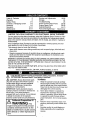
INSTALL THE UPPER HANDLE
• Cut ties securing the clutch control cables
and remote chute control cable to the
lower handle. Lay cable away from
handles.
• Remove the bolts securing the upper
handles to the lower handles. See figure
below. NOTE: Discard white plastic
washer used for shipp!pg purposes on
the right side.
o Remove upper handle assembly and
place it into operating position° Upper
handle should be on the outside of the
lower handle.
NOTE: Unless you have the assistance of
another person, it may be easier to install one
side of the handle at a time,
NOTE: Make sure the cables are not
caught between the upper and lower
handle.
• Replace the boIts, ffatwasher, Iockwasher,
and hex nuts removed earlier into the top
holes° Do not tighten°
Carria
Bert
• Install hardware supplied in parts bag
(screws, flatwashers, iockwashers, and
hex nuts) into the lower holes.
/
//../Upper
--i
• Tilt chute back into operating position.
See figure below,
handle
Remove
__latwasher
Chute in
operating_
position
_""_3/8
X 2" Screw
3/8" hex Nu__
3/8" Lockwasher
• Tighten all four bolts.
Carriage
Bolt
• Replace protective caps onto screws in
upper holes.
CONNECT
• Replace carnage bolt.
• Tighten carriage bolt securely. NOTE:
Check all bolts in chute ring for tightness.
° Remove and discard packaging used to
protect chute.
NOTE: DO NOTcut tie strap on chute deflector at this time, See second figure on
next page.
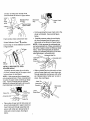
REMOTE
CHUTE
• Push remote chute control lever into
"Chute Deflector Up" f_
position,
• Feed "Z" fitting through hole in remote
chute bracket as shown in first figure on
next page,
• Snap remote chute control cable into
remote chute bracket, see next figure,
_onnect "Z" fitting into remote chute
'.ontrol bracket as shown in figure below.
:mote
_ute
_ntrol
acket
Remote Chute
Bracket
Mid.Crank
Rod
Rod
JmoteChute
Control Cable
• Cut tie securing the lower crank rod to the
chute rod bracket. See second figure
below.
Push remote chute control lever into
-
,it
"Chute Deflector Down" '_
position.
Cut tie strap on chute deflector as shown
in figure below.
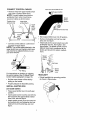
Carefully remove cotter pin and clevis
pin from universal joint in lower end of
mid-crank rod as shown in figure below.
NOTE: If this removes the universal joint
and universal joint pin° Place universal joint
into yoke of upper crank rod lining up large
holes° Insert universal joint pin (ensure
opening in universal joint pin is in line with
small openings in universal joint).
---.__
Universal Joint Pin
Lower End_"_.._-_
of Mid-
"1/_
....j Universal Joint
_
hute
eflector
',ISTALL MID-CHUTE
;et aside earlier)
ROD
Cran_
Carefully remove cotter pin and clevis
pin from universal joint in the upper crank
rod as shown in next figure.
_OTE: If this removes the universal joint
_nd universal joint pin, Place universal joint
._to yoke of upper crank rod lining up large
iotes, Insert universal joint pin (ensure
_pening in universal joint pin is in line with
;mall openings in universal joint).
_'
C,evis Pin------'-'_/
Jniversal Joint _'_'''_
_._
Upper
-"'Crank Rod
Universal
Joint Pin
-'_ Cotter Pin
• Place yoke of open end of mid-crank rod
around universal joint in upper crank rod.
Insert clevis pin through assembly and
secure with cotter pin. Spread ends of
cotter pin to lock in place, See figure
below,
a
Slide universal joint in mid-crank rod into
yoke of lower crank rod, insert clevis pin
through assembly and secure with cotter
pin. Spread ends of cotter pin to lock in
place, See next figure_
Cable Tie
Chute
Bracket
Lower
Mid-Crank
Rod
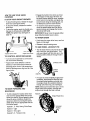
CONNECT CONTROL CABLES
• Removewrapfrom upper handle which
View from the left side of unit
gear position
was used to protect clutch levers.
NOTE: If control cables have become
unattached from motor mount frame,
reconnect cables as shown below_
Traction drive
spring (Long)
Speed
Select
Bracket
Auger drive
spring (Short)
Auger
drive
spring
cable
Control Rod
o
I
lever
• Connect control cables to control lever
as shown in figure below.
NOTE: The control cables attached to the
auger clutch lever and traction clutch lever
may need to be adjusted before you use
your snow thrower
Move speed shifter lever into R 1position,
Remove Iockwasher and nut from ball
joint, see next figure
Attach ball joint to speed select lever with
lock'washer and nut, then tighten. See
figure below. The speed control rod and
ball joint have been preadjusted at the
factory and should not require readjustment.
Speed
Control
T..m--_
Ball Joint
Z" Fitting
For instructions on checking or adjusting
the control cables, (See To Adjust Clutch
Control Cables paragraph on page 19).
• Roll the snow thrower off the skid by
pulling on the handle
, Properly dispose of discarded packing.
INSTALL
(set aside
SHIFTER
ROD
earlier)
• Place speed shifter Iever into sixth gear
position.
• Insert speed control rod (the end with the
90 ° bend) into the speed select bracket
lower hole, see next figure
• Attach speed control rod to the speed select bracket with one flatwasher and one
cotter pin found in parts bag, see next
figure _
# _
1I _',-_'-m'"
Lever
HEADLIGHT
• Rotate headlight into operating position
as shown in figure below.
J CHECKLIST
Before you operate your new snow thrower,
to ensure that you receive the best performance and satisfaction from this quality
product, please review the following
checklist:
J
,,I
,.I
All assembly instructions have been
completed.
The discharge chute rotates freely.
No remaining loose parts in carton.
KNOW
YOUR
SNOW
While learning how to use your snow
thrower, pay extra attention to the following
important items:
/J" Engine oil is at proper level°
,/#
#'/
Make sure gas tank is filled properly
with clean, fresh, unleaded gasoline°
Become familiar with all controls-their
location and function. Operate controls
before starting engine.
THROWER
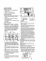
READ THIS OWNER'S MANUAL AND SAFETY RULES BEFORE OPERATING YOUR
SNOW THROWER. Compare the illustrations with your SNOW THROWER to familiarize
yourself with the location of various controls and adjustments. Save this manual for future
reference_
Engine Choke On
Run
Auger Drive
Fast
Slow
Forward
Reverse
Clutch
_
_
Discharge
chute-Right
Chute
Deflector
Down
Stop
Fuel
Oil
Primer
Button
Engage Traction
Drive
Clutch
Discharge
Ignition
chute-Left
Key
_
insert
run
)ull out
Chute
Deflector Up
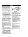
The operation of any snow thrower can result in foreign objects being thrown into the
eyes, which can result in severe eye damage° Always wear safety glasses or eye shields
while operating the snow thrower°
We recommend standard safety glasses or a wide vision safety mask for over your
glasses, available at Sears Retail Stores or Service Centers.
to
Speed Shifter Lever
.
MranK Assembly
Remote Chute Control Lever
Lever
\
Auger Drive
Electric Starter Button
Ignition
Chute Deflector
Chute
Control
Aug
Height Adjust
_er Bar
Auger Drive Lever - Starts and stops the
auger and impeller (snow gathering and
throwing),
Ignition
engine°
\
Shear Bolt
Key - Must be inserted to start the
Traction Drive Lever - Propels the snow
thrower forward and in reverse.
Primer Button - Injects fuel directly into the
carburetor manifold for fast starts in cold
weather,
Headlight - Turns on whenever engine is
running,
Recoil Starter Handle
manually°
Speed Shifter Lever - Selects the speed of
snow thrower (6 speeds forward and 2
speeds reverse).
Crank Assembly - Changes the direction of
snow throwing through the discharge chute.
Throttle Control - Controls the engine
speed,
Electric Starter Button - Used to start the
engine using the 120 V. electric starter°
Remote Chute Control Lever- Push forward to discharge snow high and far_ Pull
remote lever back to discharge snow down,
Shear Bolts - Are special bolts that are designed to break (to protect the
machine) if an object becomes lodged in
the auger housing. Use of a harder bolt will
destroy the protection provided by the shear
bolto
Chute Deflector - Changes the distance
the snow is thrown,
Discharge Chute - Changes the direction
the snow is thrown.
Choke Control
,- Used to start a cold en-
gine.
Height Adjust Skids - Adjusts the ground
clearance of the auger housing_
- Starts the engine
Toolbox - Spare shear pins and spacers
are located in toolbox.
//_
CAUTION:
Read owner's manual before operating machine, Never direct discharge
toward bystanders. Release the auger control bar and stop the engine before unclogging discharge chute or auger housing and before leaving the machine.
1o
-IOW TO USE YOUR
tHROWER
rO STOP YOUR
SNOW
SNOW
THROWER
, To stop throwing snow, release the auger
drive lever (see figure below).
, To stop the wheels, release the traction
drive lever.
• To stop the engine, push the throttle control lever to off and pull out (DO NOT
TURN) the ignition key, see figure on
page 10.
• Engage the traction drive lever as shown
in first figure on this page, left hand. As
the snow thrower starts to move, maintain
a firm hold on the handles, and guide the
snow thrower along the clearing path. Do
not attempt to push the snow thrower,
• To move the snow thrower backward,
move the speed shifter lever into first or
second reverse and engage the traction
drive lever (left hand).
IMPORTANT: Never move the speed shifter
lever while the traction lever is down.
TO THROW SNOW
• Push down the auger drive lever, see first
figure on this page.
• Release to stop throwing snow.
TO USEWHEEL
All;lht
Plan_
Auger Drive Lever
TO CONTROLSNOW
o
DISCHARGE
LOCKOUT
PIN
, The left hand wheel is secured to the axle
with a klick pin, see figure below. This
unit was shipped with this klick pin in the
locked position (klick pin through hole in
wheel).
Turn the crank assembly to set the direction of the snow throwing.
2-Wheel
Adjust snow chute deflector to set the
distance. Push remote lever forward to
discharge snow down° Pull remote lever
back to discharge snow high and far. See
figure below,
Drive
Locked
Position
• For ease of maneuverability in light snow
conditions, disconnect the klick pin from
the wheel locked position and push into
the single wheel drive position (klick pin
through axle hole only), see next figure.
TO MOVE FORWARD AND
BACKWARD
To shift, release the traction drive lever
and move the speed shifter lever to the
speed you desire'. Ground speed is determined by snow conditions. Select the
speed you desire by moving the speed
shifter lever into the appropriate area on
the control panel.
Speeds 1, 2 - Wet, Heavy, Extra Deep
Speed 3 - Light
Speed 4 - Very Light
Speeds 5, 6 - Transport only
NOTE: Make sure that the klick pin is in the
single wheel drive position, through axle
only and not through the hole in wheel.
Klick Pin
Single Wheel Drive
Unlocked
Position
BEFORE
STARTING
THE
WARNING: Experience indicates that alcohol blended fuels (called gasohol or those
using ethanol or methanol) can attract moisture which leads to separation and formation
of acids during storage,, Acidic gas can damage the fuel system of an engine while in
storage,
ENGINE
.
If the snow thrower must be moved without the aid of the engine, it is easier to pull
the snow thrower by the handles rather
than pushing.
° Before you service or start the engine, familiarize yourself with the snow thrower.
Be sure you understand the function and
location of all controls.
NOTE: Check tension of c_utch cables before starting the engine (See To Adjust The
Control Cables paragraph on page 19).
To avoid engine problems, the fuel system
should be emptied before storage for 30
days or longer. Start the" engine and let it run
until the fuel lines and carburetor are empty.
Use the carburetor bowl drain to empty residual gasoline from the float chamber, Use
fresh fuel next season (See Storage instructions on page 23 and 24 for additional
information).
o Be sure that all fasteners are tight.
• Make sure the height adjust skids are
properly adjusted (See To Adjust Skid
Height paragraph on page 18)_
• Check tire pressure (14 pounds). See
side of tire for maximum inflation. Do not
exceed listed maximum pressure.
FILL
For extreme cold operating conditions of 0°F
and below, use a partial synthetic 0W30
motor oit for easier starting.
Never use engine or carburetor cleaner
products in the fuel tank or permanent damage may occur,
Fill the fuel tank with a fresh, clean, unleaded regular, unleaded premium, or
reformulated automotive gasoline only, DO
NOT use leaded gasoline. Be sure that the
container you pour the gasoline from is
clean and free from rust or other foreign particles. Never use gasoline that may be stale
from long periods of storage in the container.
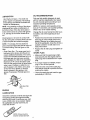
OIL
NOTE: Engine may already contain some
residual oil. Check frequently when filling the crankcase, Do not over fill,
This snow thrower was shipped with a container of 5W30 motor oil. This oil must be
added to the engine before operating_ Remove the oi! fill cap/dipstick and fill the crank
case to (FULL) line on dipstick (26 ounces)
(see figure below).
_
CAUTION: Gasoline is flammable and
caution must be used when handling or
storing it,
Do not fill fuel tank while snow thrower is
running, when it is hot, or when snow
thrower is in an enclosed area,
Fill/Dipstick
Keep away from open flame or an electrical
spark and DO NOT SMOKE while filling the
fuel tank.
NOTE: Oit level must be
between full and add
mark.
Never fill the tank completely. Fill the tank
to within 1/4" - 1/2" from the top to provide
space for expansion of fuel.
Always fill fuel tank outdoors and use a funnel or spout to prevent spilling.
Tighten the fill cap/dipstick securely each
time you check the oil leve!.
Make sure to wipe up any spilled fuel before
starting the engine.
Store gasoline in a clean, approved container and keep the cap in place on the containero
FILL GAS
NOTICE: ENGINES WHICH ARE CERTIFIED TO COMPLY WITH CALIFORNIA
AND US EPA EMISSION REGULATIONS
FOR ULGE ENGINES: Are certified to operate on regular unleaded gasoline. Include
the following emisssion control system(s):
EM, TWC (if so equipped). Include any user
adjustable features - therefore no other
adustments are needed.
TO STOP
ENGINE
To stop engine, move the throttle control
lever to _
(STOP) position and remove
key. Keep the-key in a safe place. The
engine will not start without the key.
NOTE: DO NOT turn key.
12
3 START
ENGINE
(Electric
Four times if temperature is below 15°Fo
, Push down on the starter button until the
engine starts. Do not crank for more than
t0 seconds at a time. This electric starter
is thermally protected. If overheated it will
stop automatically and can be restarted
only when it has cooled to a safe
temperature (a wait of about 5 to 10
minutes is required).
Starter)
,_sure that the engine has sufficient oil
_e snow thrower engine is equipped with a
_.0volt A,C. electric starter and recoil
artero Before starting the engine, be cerin that you have read the following information:
_
CAUTION:
This starter is equipped
with a three-wire power cord and plug
nd is designed to operate on 120 volt AC
ousehoid current, it must be properly
rounded at all times to avoid the possibility
f electrical shock which may be injurious to
peraton Follow al! instructions carefully as
et forth in the "To Start Engine" section.
)etermine that your house wiring is a threecite grounded system° Ask a licensed elect!clan if you are not sure. if your house
vire system is not a three-wire system, do
_ot use this electric starter under any condiions. if your system is grounded and a
brae-hole receptacle is not available at the
_oint your starter will normally be used, one
_hould be installed by a licensed electrician.
_hen connecting 120 volt AC power cord,
_tways connect the cord to the switch box
on the engine first, then plug the other end
into the three-hole grounded receptacle.
When disconnecting power cord, always
unplug the end in the three-hole grounded
receptacle first.
• When the engine starts, release the
starter button and move choke lever to "1/
2 choke" position. When engine runs
smoothly, move choke lever to "No
Choke" Position_
• Disconnect the power cord from the
receptacle first and then from the switch
box on engine.
NOTE: Allow the engine to warm up for
several minutes before blowing snow in
temperatures below 0°Fo
• Run the engine at full throttle "f_ (FAST)
when throwing snow.
TO START
Starter)
COLD START
° Be sure the auger drive and traction drive
levers are in the disengaged (released)
position.
. Be sure the auger drive and traction drive
levers are in the disengaged (released)
position,
, Move the throttle control to '_ (FAST)
position, See figure on page 10.
• Remove the keys from the plastic bag.
Insert one key into the ignition slot. Be
sure it snaps into place, DO NOT TURN
KEY. Keep the second key in a safe
place.
• Move the throttle control to "_ (FAST)
position. See figure on page 10 for location,
° Remove the keys from the plastic bag. Insert one key into the ignition slot. Be sure
it snaps into place. DO NOT TURN KEY.
Keep the second key in a safe place.
• Rotate the choke knob to H choke
ON position. See figure on page 10.
• Rotate the choke knob to H choke ON
position. See figure on page 10.
• Push the primer button, see figure on
page 10, while covering the vent hole as
follows: (Remove finger from primer button between primes).
• Connect the power cord to the switch box
on the engine_
• Plug the other end of the power cord into
a three-hole, grour_ded 120 volt ArC.
receptacle.
, Push the primer button while covering the
vent hole as follows: (Remove finger from
primer button between primes). See
figure on page t0 for location.
Two times if temperature
(Recoil
Be sure that the engine has sufficient oil.
The snow thrower engine is equipped with a
recoil starter. Before starting the engine, be
certain that you have read the following information:
COLD START
Do not prime it temperature
50°F.
ENGINE
Do not prime if temperature
50oE
Two times if temperature
Four times if temperature
is above
is 50°F to 15°E
is below
15°E
• Pull the recoil starter handle rapidly. Do
not allow the handle to snap back, but allow it to rewind slowly while keeping a
firm hold on the starter handle.
is above
is 50°F to 15°F.
13
., As engine starts warms up move choke
lever to "1/2 choke" position. When engine
runs smoothly, move choke lever to "No
Choke" Position
Do no attempt to remove
any item that may become lodged in
auger without taking the following precautions:
NOTE: Allow the engine to warm up for
several minutes before blowing snow in temperatures below 0°F.
• Release auger drive and traction drive
levers°
• Run the engine at full throttle _
when throwing snow.
• Remove (DO NOT TURN) ignition key.
WARM
/_
CAUTION:
° Move throttle lever to stop position.
(FAST)
• Disconnect spark,prug wire.
START
• Do not place your hands in the auger or
discharge chute. Use a pry bar.
If restarting a warm engine after a short
shutdown, leave choke at (OFF) and do not
push the primer button. If the engine fails to
start, follow the Cold Start instructions
above.
SNOW THROWING TIPS
• For maximum snow thrower efficiency in
removing snow, adjust ground speed,
NEVER the throttle° Go slower in deep,
freezing, or wet snow. If the wheels slip,
reduce forward speed. The engine is designed to deliver maximum performance
at full throttle and should be run at this
power setting at all times. Most efficient
snow blowing is accomplished when the
snow is removed immediately after it falls.
FROZEN RECOIL STARTER
If the starter is frozen and will not turn
engine:
, Pull as much rope out of the starter as
possible.
• Release the starter handle and let it snap
back against the starter.
If the starter still fails to turn engine, repeat
the two previous steps until the starter en.
gages, Then continue with the directions for
cold start,
• Forcomplete snow removal, slightly overlap each path previously taken. Use more
overlap in deep snow to prevent overloading,
To help prevent possible freeze-up of recoil
starter and engine controls, proceed as follows after each snow removal job.
• The snow should be discharged down
wind whenever possible. In windy conditions, lower the chute deflector to direct
discharged snow close to the ground,
where it is less likely to blow into unwanted areas.
• With the engine running, pull the starter
rope hard with a continuous full arm
stroke three or four times. Pulling of
starter rope will produce a loud clattering
sound. This is not harmful to the engine or
starter.
• For normal usage, set the skids so that
the scraper bar is 1/8" above the skids.
For extremely hard-packed snow surfaces, adjust the skids upward so that the
scraper bar touches the ground°
° With the engine not running, wipe al!
snow and moisture from the carburetor
cover in area of control levers. Also move
throttle control, choke control, and starter
handle several times.
° On gravel or crushed rock surfaces, set
the skids at t-1/4" below the scraper bar
(See To Adjust Skids Height paragraph on
page I8)_ Stones and gravel must not be
picked up and thrown by the machine.
° After the snow throwing job has been
completed, allow the engine to idle for a
few minutes, which will melt snow and accumulated ice off the engine.
Z_
CAUTION:
Never run engine indoors
or in enclosed, poorly ventilated areas.
Engine exhaust contains carbon monoxide,
an odorless and deadly gas. Keep hands,
feet, hair and loose clothing away from any
moving parts on engine and snow thrower_
WARNING:
Temperature of muffler and
nearby areas may exceed 150 ° F. Avoid
these areas.
• Clean the snow thrower thoroughly
each use.
after
• Remove ice and snow accumulation and
all debris from the entire snow thrower,
and flush with water (if possible) to remove all salt or other chemicals. Wipe
,snow thrower dry_
DO NOT allow children or young teenagers
to operate or be near snow thrower while it
is operating°
_4
CUSTOMER
RESPONSIBILITIES
SERVICE
DATES
SCHEDULE
SERVICE
RECORDS
............................
As
Every Ev
Fill in dates as
you complete
regular service
After
Befor_
first 2 Each
Hours Use
Needed
5
10
Hours Hours
................
Each
Before
Every
25
Hours
Season
Storage
I
;TightenAftScrews& Nuts
Lubricate
PivotPoints
_,_
- .................
......
Lubricate Auger Shaft (See
ShearBolt Replacement
v_
v"
11
LubricateDiscDrivePlateZerl_
v"
Check Spark Plug
Check Engine Oil Level
V 't
ChangeEngineOil
_'_
_'
v"
....
CheckFuet
.,,--4
...j
,_J
Drain Fuel
Check Auger Clulch Cable
Adjustment(SeeCabieAdj) _
CheckTractionClutchCable
Adiustment(See Cable Adt)
CheckDrive Belts
PRODUCT
,_I
v,"
.......
j
HORSE POWER:
II HP
Some adjustments will need to be made periodically to properly maintain your snow
thrower,
DISPLACEMENT:
21,82 cu, ino
LUBRICATION
GASOLINE
SPECIFICATIONS
CAPACITY:
OIL (26 oz. Capacity) :
SPARK PLUG:
VALVE CLEARANCE:
CHART
4 quart
(unleaded)
Lubricate
Disc Drive
Plate Zerk
with a Hi
Tamp EP
Moiy Grease,
5W-30
Champion RJ19LM
(Gap .030) or
Equivalent
Intake: 0_10 In,
Exhaust: ,010 In.
GENERAL
RECOMMENDATIONS
The warranty on this. snow thrower does not
cover items that have been subjected to operator abuse or negligence. To receive full
value from the warranty, the operator must
maintain the snow thrower as instructed in
this manual. The above chart is provided to
assist the operator in properly maintaining
the snow thrower,
Lubricate the Auger Shaft,
Coat with a clinging type grease
such as Lubriplate or fiber
impregnated grease,
15
SNOW
AFTER
THROWER
FIRST
Rubber_
Friction
USE
• Tighten any loose fasteners.
• Check and maintain the auger.
EACH
USE
Friction
Wheel
• Remove all snow and slush off the snow
thrower to prevent freezing of auger or
controls.
° if any parts are worn or damaged, replace
immediately°
THROWER
LUBRICATION-
Plate
Grease
kl/Bearing
Assembl
Place coin in gap
between friction
wheel and disc drive
plate
I
,,I
[_________--_--!{--G
reas e Zerk
• Check controls to make sure they are
functioning properly,
SNOW
Disc
Wheel /,_
Gears
(Require
1
No
.....
Lubrication)
o Check for any loose or damaged parts
after each use,
AFTER
Shaft
_!
• Remove the bottom
figure on page 21).
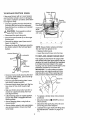
EVERY 10 HOURS
grease
should be visible
panel (see second
, Turn disc drive plate clockwise by hand
until grease zerk is clearly visible at front
center. See next figure.
• Place a coin or (a shim of equal thickness) between the rubber friction wheel
and disc drive plate to prevent rubber friction wheel contacting the drive disc.
• Auger Shaft - Using a hand grease gun,
lubricate the auger shaft zerk fittings (See
figure below) every ten (10) operating
hours. Each time a shear bolt is replaced
(See To Replace Auger Shear Bolt on
page 22), the auger shaft MUST be
greased.
• To grease zerk, use a hand grease gun,
lubricate with a Hi Temp EP Moiy grease
See inset of figure above° DO NOT over
fill or allow grease to come in contact with
the disc drive plate or friction wheel or
damage will result. Fill zerk only until
grease becomes visible below bearing assembly located under grease zerk see im
sert above.
IMPORTANT: Remove coin and ensure that
a gap exists between friction wheel and disc
drive plate.
• For storage or when replacing shear
bolts, remove shear bolts and lubricate
auger shaft zerks, Rotate augers several
times on the shaft and reinstall the shear
bolts.
NOTE: Clean all excess grease found on
friction disc hub.
CAUTION; Do not allow grease to contact
friction wheel and disc drive plate.
• See Lubrication Chart diagram on page
15 for lubrication points and type of lubricant.
LUBRICATION
LUBRICATION
- BEFORE
STORAGE
Remove both wheels, grease (any automotive type grease) both axles, see figure
below, and replace wheels° Do this at
least once a year and/or prior to storage°
- EVERY 25 HOURS
• Lubricate Disc Drive Plate every twentyfive (25) hours and at the end of the season and/or before storage.
To Lubricate:
• Position speed selector lever in first gear.
• Stand the snow thrower up on the auger
housing end.
Axle
16
OIL RECOMMENDATION
.UBRICATION
Hex Shaft and Gears - Hex shaft and
Only use high quality detergent oil rated
with API service classification SG. Select
gears require no lubrication. All bearings
and bushings are lifetime lubricated and
require no maintenance°
the oil's viscosity grade according to your
expected operating temperature:
_IOTE" Any greasing or oiling of the above
:omponents can cause contamination of
he friction wheel. If the disc drive plate or
riction wheel comes in contact with grease
)r oil, damage to the friction wheel will re;ult,
NOTE: For extreme cold operating conditions of 0 ° and below, use a partial synthetic
0W30 motor oil for easier starting.
_hould grease or oil come in contact with
he disc drive plate or friction wheel, be sure
o clean the plate and wheel thoroughly.
• Position the snow thrower so that the oil
drain plug is at the lowest point on the
engine. Remove the oi! drain plug and
the oil fill cap/dipstick. Drain the oil into a
suitable container_ Oil will drain more
freely when warm.
Change the oil every twenty-five (25) hours
thereafter, and at the beginning of each
season.
_!OTE: For storage, the hex shaft and
]ears should be wiped with 5W-30 motor oil
:o prevent rusting. See first figure on this
_age.
• Replace the oil drain plug and tighten securely.
, Auger Gear Box - The auger gear box is
lubricated at the factory and should not
require additional lubrication. If for some
reason the lubricant should leak out, or if
the auger gear box has been serviced,
add Lubriplate No. 630-AA or equivalent_
Maximum 3-1/4 ounces should be used.
SPARK
PLUG
• Make sure that the spark plug is tightened securely into the engine and the
spark plug wire is attached to the spark
plug_
. If a torque wrench is available, torque
plug to 18 to 23 foot pounds.
Remove filler plug as seen in figure below
once a year. If grease is visible, do not
add. If grease is not visible, use a piece
of fine wire like a dipstick, to check if
there is grease in the gearbox. Add
grease if necessary. Reinstall gear box
filler.
. Clean the area around the spark plug
base before removal to prevent dirt from
entering the engine.
o Clean the spark plug and reset the gap
pedodically at .030 inch.
Gear Box Filler
Plug
ENGINE
LUBRICATION
Check the crankcase oil level (see figure below) before starting tbe engine and after
each five (5) hours of continuous use. Add
S_A.E. 5W30 motor oil as needed. Tighten
fill cap/dipstick securely each time you
check the oil level.
el must be
nd add mark
17
Z_
CAUTION:
Always disconnect the
spark plug wire and tie back away from
the plug before making any adjustments
or repairs,
TO ADJUST
SKID HEIGHT
This snow thrower is equipped with two
height adjustment skids, located on the outside of the auger housing (see figure below). These skids elevate the front of the
snow thrower..
Auger Housin
TO ADJUST SCRAPER
BAR
After considerable use, the metaI scraper
bar will have a definite wear pattern. The
scraper bar in conjunction with the skids
should always be adjusted to allow 1/8" between the scraper bar.arid the sidewalk or
area to be cleaned° The scraper bar may
have to be returned to its original lower setting to maintain the original performance
level. To adjust:
• Position the snow thrower on a level surface.
• Make sure both tires are equally inflated.
• Loosen the carriage bolts and nuts securing the scraper bar to the auger housing.
Height Adjust
• Adjust the scraper bar to the proper position.
• Tighten the carriage bolts and nuts, making sure that the scraper bar is parallel
with the working surface.
Skid Mounting Nuts
For normal hard surfaces,
as follows:
adjust the Skids
• Check tire pressure (14 pounds). See
side of tire for maximum inflation. Do not
exceed maximum pressure on side of
tire.
• Place the extra shear bolts supplied
(found in parts bag) under each end of
the scraper bar near but not under the
skid.
• Loosen the skid mounting nuts (see figure above) and adjust the skids up to
bring the front of the snow thrower down.
• Re-tighten the mounting nuts.
° Set the skid on the other side at the same
height.
For rocky or uneven surfaces,
skids as follows:
adjust the
• Raise the front of the snow thrower by
moving the skids down. This will help prevent rocks and other debris from being
picked up and thrown by the auger°
NOTE: Be sure that snow thrower is set at
same height on both sides.
o For extended operation, the scraper bar
may be reversed. If the scraper bar must
be replaced due to wear, remove the carriage bolts and nuts and install a new
scraper bar.
,4k CAUTION:
Be certain to maintain
proper ground clearance for your par..
ticular area to be cleared. Objects such as
gravel, rocks or other debris, if struck by the
impeller, may be thrown with sufficient force
to cause personal injury, property damage
or damage to the snow thrower.
:_ _':iii'_i_i
_'': °
i7!_:,:,!i
_:¸_,:/__
¸;¸,:8¸¸
i:
71
FO ADJUST'THE
CLUTCH
CONTROL
3ABLES
%riodic adjustment of the cables may be
"equired due to normal stretch and wear on
:he belts. To check for correct adjustment,
:lisconnect "Z" Fitting at clutch lever, move
clutch lever to the full forward position, just
contacting the plastic bumper. The control
cables are correctly adjusted when the center of the "Z" fitting is between the center
and top of the hole and there is no droop in
the cable (see figure below). If adjustment is
necessary:
Control Lever
in tuti
Plastic
Bumper
forwardposition
(JustContacting
PlasticBumper)
whenchecking
TO ADJUST
BELTS
Belts stretch during normal use, If you need
to adjust the belts due to wear or stretch,
proceed as follows:
AUGER DRIVE BELT
If your snow thrower w!ll not discharge
snow, check the control cable adjustment. If
it is correct, then checkthe condition of the
auger drive belt. It may be loose or damaged. If it is damaged, replace it (See To
Replace Belts paragraph on page 20). If the
auger drive belt is loose, adjust as follows:
• Disconnect the spark plug wire.
• Remove the belt cover (See second
figure on page 20)+
• Loosen the nut on the auger idler pulley
(See figure below) and move the pulley
toward the belt about 1/8%
o Tighten the nut.
"Z" Fitting
Traction
Remove fuei from tank, and stand blower
on end.
t
Pull rubber boot off the top of the spring.
Push the cable through the spring (see
figure below) to expose the threaded portion of the cable.
Cable sprin!
Traction
Drive Belt
\
Auger Drive Belt Drive
Idler
Belt Guide
(Left Hand)
nut
Belt
Guide
(Right
Hand)
Auger Idler
Pultey
uare end
, Press the auger drive lever. Check the
tension on the belt (opposite auger idler
pulley). The belt should deflect about
I/2" with moderate pressure (See figure
below)+
NOTE" You may have to move the auger
idler pulley more than once to obtain the
correct tension,
• Hold the square end of the threaded por.tion with pliers and adjust the Iocknut in or
out until the excess slack is removed.
• Pull the cable back through the spring
and connect the cable,
• Do the same for the other lever cable, if
_
Auger Idler _
Engaged
Pulley
Drive Pulley
,._,_112
/_
inch
Deflection
TO REPLACE
FRICTION
Friction
WHEEL
tf the snow thrower will not move forward,
and the friction wheel is worn or damaged,
you need to replace it as follows: (First allow
the engine to cool).
Bearing
Plate Bolts
• Drain the gasoline from the fuel tank by
removing the fuel line at the carburetor.
Drain the fuel in a container and reinstall
the fuel line.
Z_
Fasteners
(Bolts,
Auger
CAUTION:
Drain gasoline outdoor
away from fire or flame.
• Disconnect
the spark p_ug wire.
and nutsl/,,
/
{
• Stand the snow thrower up on the auger
housing end.
• Remove the bottom panel (see second
figure on page 21).
• Remove the three (3) fasteners securing
the friction wheel to the hub (see figure
below),
NOTE: Ensure friction wheel and friction
disc are free from grease or oilo
• Replace bottom panel,
• Lower the snow thrower onto the tires.
Friction Wheef'_
'_k ,,. Lockwasher
TO REPLACE
Bolt -,-_
-_H_x
The augers are secured to the auger shaft
with special bolts (see figure below) that are
designed to break (to protect the machine)
if an object becomes lodged in the auger
housing. Use of a harder bolt will destroy the
protection provided by the shear bolt.
IMPORTANT; To ensure safety and performance levels, only original equipment shear
bolts should be used. When replacing shear
bolts, be sure to replace shear bolt spacers°
Shaft
./
Bolt
AUGER SHEAR BOLT
"-Lockwasher
• Remove the four bolts securing the bearing plates (both sides), (see second figure on this page).
Shear Pin
• Remove right side bearing plate. Leave
hex shaft in original position.
• Remove friction wheel from hub° Slip friction wheel off hex shaft towards right
side.
}acer
• Slip new friction wheel onto hub with recessed or cupped end away from hub
(see figure above).
/
• Ins'tall bearing plates to odginal position.
Ensure hex shaft is engaged with both
bearing plates,
° To replace a broken shear bolt, proceed
as follows:
• Move the throttle to I_ (STOP) and turn
off all controls.
• Secure bearing plates, using bolts removed earlier.
• Disconnect the spark plug wire. Be sure
all moving parts have stopped.
• Secure friction wheel to hub using fasteners removed earlier. Ensure hex shaft
turns freely.
• Lubricate the auger shaft zerk fitting (See
the Maintenance section on pages 15t7).
22
• Align the hole in the auger with the hole
in the auger shaft° Install the new shear
pin and spacer found in toolbox located
on top of belt cover,
TO ADJUST:
NOTE: The spacer fits inside the larger
hole in the auger tube.
• Reconnect the spark plug wire.
• Be sure the spark plug is clean and free
of foreign material. Check the electrodes
gap (see figure below) with a wire feeler
gauge and reset the gap to .030 inch if
necessary,
TO ADJUST
CARBURETOR
• Clean the spark plug by carefully scraping the electrodes (do not sand blast or
use a wire brush),
If you think your carburetor needs adjusting,
see your nearest Authorized Sears Service
Center. Engine performance should not be
affected at altitudes up to 7,000 feet. For
operation at higher elevations, contact your
nearest Sears Service Center.
TO ADJUST
OR REPLACE
THE SPARK PLUG
TO REPLACE:
NOTICE: This spark ignition system meets
all requirements of the Canadian Interference-Causing Equipment Regulations.
• tf you need a new spark plug, use only
the proper replacement spark plug (see
page t5).
NOTICE: This engine complies with all current Australian and New Zealand limitaions
• Set the gap to .030.
regarding electromagnetic
interference.
If you have difficulty starting your snow
thrower, you may need to adjust or replace
the spark plug. Follow the instructions below.
Replace the spark plug if the electrodes are
pitted or burned or if the porcelain is
cracked.
• Before installing the spark plug, coat its
threads lightly with oil or grease to insure
easy removal.
• Tighten the plug firmly into the engine.
. if a torque wrench is available, torque the
plug to 18 to 23 ft. - lbs.
Z_ CAUTION:
Never store your snow
thrower indoors or in an enclosed, poorly
ventilated area ff gasoline remains in the
tank. fumes may reach an open flame,
spark or pilot light from a furnace, water
heater, clothes dryer, cigarette, etc.
To prevent engine damage (if snow thrower
is not used for more than 30 days) follow
the steps below.
SNOW THROWER
• Thoroughly
Carburetor
STORAGE
clean the snow thrower.
o Lubricate all lubrication points (see the
Maintenance section on pages 15-17).
• Be sure that all nuts, bolts and screws are
securely fastened. Inspect all visible moving pads for damage, breakage and wear.
Replace if necessary.
Always follow instructions on stabilizer container. Then run engine at least 10 minutes
after stabilizer is added to allow mixture to
reach carburetor. Store snow thrower in a
safe place. See Caution on this page,
You can keep your engine in good operating
condition during storage by:
° Changing oil (see page 17)4
, Lubricating the piston/cyfinder area.. This
can be done by first removing the spark
plug and squirting a few drops of clean
engine oil into the spark plug holeo Then
cover the spark plug hole with a rag to
absorb oil spray. Next, rotate the engine
by pulling the starter rope fully out two or
three times. Finally, reinstall spark plug
and attach spark plug wire.
• Touch up all rusted or chipped paint surfaces; sand lightly before painting.
• Cover the b-are metal parts of the blower
housing auger and the impeller with rust
preventative, such as a spray lubricant°
NOTE: A yearly checkup or tune-up by a
SEARS Service Center is a good way to insure that your snow thrower will provide
maximum performance for the next season.
ENGINE
Bowl
STORAGE
OTHER
Gasoline must be removed or treated to prevent gum deposits from forming in the tank,
filter, hose, and carburetor during storage.
Also during storage, alcohol blended gasoline that uses ethanol or methanol (sometimes called gasohol) attracts water. It acts
on the gasoline to form acids which damage
the engine.
• To remove gasoline, run the engine until
the tank is empty and the engine stops.
Then drain remaining gasoline from carburetor by pressing upward on bowl drain
located on the bottom of carburetor (see
next figure).
• tf you do not want to remove gasoline, a
fuel stabilizer (such as Craftsman Fuel
Stabilizer No, 33500) may be added to
any gasoline left in the tank to minimize
gum deposits and acids° If the tank is almost empty, mix stabilizer with fresh gaso..
line in a separate container and add some
to the tank.
24
" If possible, store your snow thrower indoors and cover it to give protection from
dust and dirt.
• If the machine must be stored outdoors,
block up the snow thrower to be sure the
entire machine is off the ground.
, Cover the snow thrower with a suitable
protective cover that does not retain
moisture. Do not use plastic or vinyl.
IMPORTANT:
Never cover snow thrower
while engine and exhaust areas are still
warm.
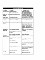
TROUBLE
CAUSE
Difficult starting
CORRECTION
Defective spark pIug
Replace defective plug
Water or dirt in fuel system
Use carburetor bowt drain to
flush and refill with fresh fuel
Blocked fuel line or tow on fuel
Clean fuel line; check fuei supply; add fresh gasoline (gasoline/oil mixture if 2-cycie engine)
Unit running on CHOKE
Move choke lever to OFF positior
Water or dirt in fuel system
LJse carburetor bowl drain to
flush and refill with fresh fuel
Excessive
vibration
Loose parts; damaged impeller
Stop engine immediately and
disconnect spark plug wire.
Tighten all bolts and make all
necessary repairs_ if vibration
continues, have the unit serviced by a Sears service repairman
Units fails to
propel itself
Drive belt loose or damaged
Adjust auger drive belt: Replace
if damaged
incorrect adjustment of auger contro! cable
Adjust traction drive cable
Engine runs
ratically
er-
Engine stalls
Engine runs
ratically;
Loss
er-
of power
Unit fails to
discharge
Headlight
not work
Worn or damaged friction wheel
Repair friction wheel
Auger drive belt loose or damaged
Replace auger drive belt
Auger control cable not adjusted
correctly
Adjust auger control cable
Shear bolt broken
Replace shear bolt
Discharge chute clogged
Stop engine immediately and dis.
connect spark plug wire° Clean
discharge chute and inside of auger housing
Foreign object lodged in auger
Stop engine immediately and dis_
connect spark plug wire. Remove
object from auger.
snow
does
Loose wire connection
Tighten connection
Bulb burned out
Replace headlight bulb
25
CRAFTSMAN
---i
30"-
11H.P.
ELECTRIC
SNOW
THROWER
536.886220
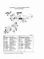
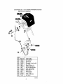
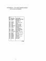
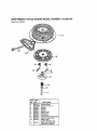
START ASSEMBLY
.,_-_"_::...
REF
NO.
_,.
.i ::,
"_]
!_ ""
I
_
il
_ ':
PART NO.
6
7
8
9
6218
6216
6217
6219
761118
PART NAME
Starter Motor
Screw, 1/4-20X .50
Screw, #6-32X2°50
Cord, Starter Motor
Owner's Manual Eng/Sp
319051B
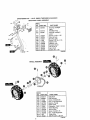
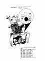
ENGINE ASSEMBLY
REF_
NO. | PART NO.
,j ENGINE
12
13
31
33
34
41
43
44
5'1
J
331216
120638
3949
l 120638
I 910828
I 3949
1 120638
91O828
579855
PART NAME
Model 143.981001
(See Engine Pages)
Screw, 5/16-18X1.50
Washer, Hvsptlk
Belt Guide RH
Washer, Hvsp_lk
Screw, 5116-24X 1..00
Belt Guide RH
Washer, Hvsptlk
Screw, 5tl 6-24X 1.00
Washer, Crankshaft
Note; Always use original equipment parts. Use of
ser¢i_e/reptacement parts other than odginal parts
may void your warranty°
REF,
NO. PART NOo
53
54
57
58
59
60
63
57
68
69
579854
579861
579932
73840
586251
586253
585416
313826
120382
39573
PART NAME
Pulley Half
Flatwasher.752X .91X.02
Belt, V
Flatwasher .765X1.12X_06
Spacer Sleeve
Engine Pulley V4L
Belt, V 4L
Flatwasher
Washer, Regsptlk
Screw 3/8-24X1 00
319042G
All unnumbered items are
interchangeable
with opposite side
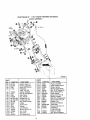
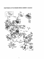
CRAFTSMAN
30" - 11H.P. SNOW THROWER
536.886220
FRAME ASSEMBLY
342574B
I REF.{
_NO. I PARTNOo
340386-848
i8oi
88
780055
REF.
NO.
PART NAME
Frame Assy
Screw, 5/16-t8X 30
583031-8481
90
Cover, Bottom Wheel
:91
310169
Screw, 1/4-20X .63
100 I 761195
Plate, Clutch Arm
ldJer Bracket
103 1 761196
104 I 710200
Sh. Bolt, 3/8-16
105 t 780072
Nut, 3/8-16
106 I 340682
Cable Clip
108 ! 761153
Cable, Auger
109 I 340869
Shield, Cable Guard
110 I 585781
Bolt, 3/8-16XIo25
111
996418
, Flatwasher, 506xo75x.024
112 I 313843
Idler Pulley
t15 I 41529
Nut, 3/8-16 Hxctrtkjam
116 I 585470
Bolt, Brake Arm
117 I 585608
Nut, 9/16-18 Jamctdk
118 I 585446
Bolt-Brake Arm
119 I 73801
Pin, Spdng
120 I 581540
Pad, Auger/Impeller Brake
121 761197
Bracket
122 I 585609
Nut, 1/2-20 Jamctrlk
123 I 1499
Nut, 3/8..16 Reghxctrlk
PART NAME
124 1710138
125 120382
126 782585
I27 48306
t28 58336
t29
120385
i
133
140
141
142
143
144
145
t46
148
149
160
161
162
t63
27
339017
579872
180077
73795
579865
71038
313854
180124
313843
41529
760478
310169
71067
760539
Stud, Brake Arm
Washer, Regsptlk
Nut, 1/4-20 Reghexctrlk
Pulley
Bolt, .375 x .375
Washer, Flat
,250 x .56 x .049
Idler Spring
Idler Arm Lever
Screw 5/16.18X °75
Flatwasher .328X1.25X.075
Bushing, }dler Lever
Nut, 5/16-18 Hexnly
;dterSpring
Screw, 3/8-16X1.25
Idler Pulley
Nut 3/8-16 Hxctrlkjam
Belt Cover
Screw, 1/4-20X ,63
Flatwasher .286X63X,065
Lid, Belt Cover
CRAFTSMAN
30" - 11H+P. SNOW THROWER
536.886220
DRIVE ASSEMBLY
O
@
@
313995 J
I
REF.
NO.
PART NO.
190
19t
192
193
195
t96
I98
210
211
215
216
217
579941
313853
137185
313919
579937
11871
782585
583163+853
583206
583155
85501
71074
221
222
73811
580969
223
224
225
226
227
43846
580970
580961
580965
578962
228
120380
PART NAME
PART NO.
LeverAssy
Bearing Flange
Cotter Pin
Spring, Return
Lever, Spring Traction
Screw t/4-20X ,63
Nut, 1/4-20 Reghexctrlk
Disc Assy
Grease Zerk
Hex Shaft
Trunion Bearing
Flatwasher
.53 X1.00X+063
Retex Ring
Ftatwasher
.680X1+12X.060
Ball Bearing
Square Key. 18SQX.63LG
Pulley, V3L 6°50X _56
Wave Washer
Flatwasher
.281X1.00X+063
Washer, Regsp!tck
[229
230
231
232
i235
240
243
244
245
246
247
249
250
255
256
257
270
271
1275
1276
277
278
28
18002o
334163
780055
120638
579858
579897
462
71074
337029
313883
11871
303008
579858
334163
780055
120638
334163
780055
5830'10
334163
780055
579867
PART NAME .........
Screw, 1/4-20X .75
Bearing and Retainer Assy
Screw 5/16-18X .50
Washer, Hvsptik
Special Washer
Hex Assy #40-8TW
Retex Ring
Flatwasher +53X 1 00X 063
Trunion Bearing
Friction Wheel Assy
Screw, 1/4-20X .63
Nut 1/4-20 Hex Keps
Special Washer
Bearing and Retainer Assy
Screw 5116-18X _80
Washer, Hvsptik
Bearing and Retainer Assy
Screw, 5/16+18X .50
Jack Assy#41-36T&TT
Bearing and Retainer Assy
Screw, 5/16+18X .50
Chain Roller #42 X 40P
I
CRAFTSMAN30"
- 11H.P. SNOW THROWER
GEAR CASE ASSEMBLY
536,886220
314014D
REF.I
NO_9=ART
NO.
896
895
910828
71100
330434
313872
780151
313870
313871
760527
897
j3141
1315,,,I313861
300
301
303
3O4
305
306
310
311
312
313
I
I
I
I
I
I
I
I
I
1
PART NAME
Gear Case RH
Gear Case LH
Screw, 5/16-24Xl ,00
Nut, 5/t6-24
Screw, 5/16=24Xl °50
Pipe Plut
Oil Sea_
Bearing Sleeve
Flat'washer
Auger Shaft
Gasket, Gear Box
Worm Gear
29
JREF
NO.
PART NO.
3t6
32O
321
322
323
324
326
327
33O
340
73905
313914
583126
48275
313828
48275
50795
313862
53731
585423-853
PART NAME
Woodruff Key#91
Ring, Quad
Bearing. Flange
Flatwasher .752X1,24Xo093
Bearing, Roll
Flatwasher .752X1 24X,093
HFPro Key 606
Worm Gear
Bearing. Sleeve
impeller Assy
CRAFTSMAN 30" - 11H.P° SNOW THROWER
DISCHARGE CHUTE ASSEMBLY
536.886220
f_
REF,
NO, PART NO.
580
582
584
585
586
587
600
601
602
761168-853
578088
71038
578088
6711
71038
761169-853
586280
120393
603
608
607
608
71038
585214-853
302628
i71067
609 782585
610 337227
611 585193
PART NAME
Upper Chute
Screw, 5/16-18X ,75
Nut, 5/16-18 Reghxctrtk
Screw, 5/16-18X .75
Plastic Washer,
Nut, 5/16-18 Reghxctrlk
Lower Chute
Bolt, 5/t 6-18X1.00
Flatwasher
.344X ,69X.065
Nut, 5/16-18 Hexnyl
Chute Collar
Screw, 1/4-20X 75
Flatwasher
,286X,63Xo065
Nut, 1/4-20 Reghxctrtk
Inner Ring Retainer
Outer Ring Retainer
340892E-1
3O
i
CRAFTSMAN
30" -11H.P.
SNOW THROWER
536.886220
AUGER HOUSING ASSEMBLY
@
339974 M
REF.
NO.
480
482
483
PART NO.
PART NAME
583146
71371
71074
Pulley, V4L 8.40 OD
Square Key, 16SQX.88LG
Flatwasher
.53 X1_00X,063
Nut, 1/2-20 Reghxctdk
Spacer, Sleeve
Ball Bearing Retainer
Ball Bearing
Screw, 5/16-18X .75
Nut, 5/16-18 Reghex
Housing Assy
Plug
Scraper Blade
Bolt, 5/16-18X .75
Nut, 5/16-18 Hxwdfllk
Whiz
Auger Assy RH
484
485
490
491
493
499
5O0
5O9
510
511
514
274654
334514
582960
43846
180077
710026
760666-648
760040
760659-853
340720
710026
520
760595-853
REF.
NO.
52I
522
523
524
525
526
PART NO.
760596-853
3943
313873
73755
527
540
541
542
782967
585385-853
340720
120393
543
544
120638
120376
* When ordering replacement parts order Shear Pin, part #760875.
3_
PART NAME
Auger Assy LH
Screw, 114o20X1.75
Spacer Stebve
Nut, 1/4-20 Reghxctrlk
Auger Shaft Bearing
Flatwasher
1.005X1.31X.035
Screw, 5/16-18X .88
Height Adj° Skid
Bolt, 5/16-18X .75
Flatwasher
°344X .69Xo065
Washer, HvsptIk
Nut, 5116-18 Reghex
CRAFTSMAN
30"-11H.P.
SNOW THROWER
536.886220
HEADLIGHT PANEL ASSEMBLY
REF.
NO, PART NO.
°,,=!41!']J
g21
' :,
620
583490
621
622
581575
583491
623
180024
760745
760821
11234
120393
120638
760482
120376
782585
307781
624
625
,
i626
627
628
629
830
631
832
PART NAME
Housing, headlight
Upper
Headlight Assy
Housing, headlight
Lower
Screw, 114-20x 125
Wire Harness
Bracket, Light
Screw, 5/16-18 x 2.75
Washer, Fiat
Washer, Lock
Bracket, Mount
Nut, 5116-18
Nut, 1/4-20
Screw, #8 x 1.75
3426236
WHEEL ASSEMBLY
I
O
REF.
NO. PART NO.
650 5830 7
652
653
i654
655
'656
671
673
675
676
'677
678
679
32
583007
73839
782585
581730
583013
73840
585591
584633
577015
782585
239
73842
PART NAME
Axle Shaft
.....
Hub Sprocket
Screw, 1/4-20X225
Nut, 1/4-20 Reghxctrik
Bearing, Flange
Roller Chain
Flatwasher o765X1.12X06
Wheel Bushing
_re and Rim
Screw 1/4-20X1 ..76
Nut, 1/4-20 Reghxctdk
Retex Ring
Klik Pin .25 X 1.38 DIA
318542F
CRAFTSMAN
30" '11H.P. SNOW THROWER
HANDI.E ASSEMBLY
536.886220
°o
340090K_1
REF,
NO.
720
721
724
725
581736
581738
7268
71072
726
727
728
729
730
731
732
733
734
735
736
737
738
739
740
120382
1499
7289
578328
581761-853
581758-653
581766
300311
3535
4049
579057
180016
782585
8417
584673
PAR1"NO,
REF,
'NO.
PART NAME
Handle, Upper LH
Handle, Upper RH
Screw, 3/8-16X300
Flatwasher
.406X _81X.066
Washer, Regsptik
Nut, 3/8-16 reghxctrlk
Stop, Plastic
Grip, Handte
Handle Assy, LH
Handle Assy, RH
Rod, Clutch Handle
E Ring
Push-onNut
Bumper
Cam Bracket
Screw, 1/4-20X 50
Nut, 1/4-20
Cam Lock,
Pin, Spring Pivot
33
PART NO.
741
'742
743
744
745
746
750
751
752
753
754
755
756
760
761
762
73664
579257
579869
I673
782585
308146
5543-853
782967
120638
1498
180079
302680
71007
578330-853
302900
120393
763
764
120638
120376
PART NAME
Push-on Nut 3/8"
Cable, Clutch Control
Tension Spring
Spring, Auger Clutch
Nut, 1/4-20 Reghxctrlk
Boot, Clutch Spring
LowerHandle
Screw, 5/16-16X .88
Washer, Hvsptlk
Nut, 5/16-18 Reghxctdk
Screw, 5/16-18X 1.00
Washer, Flat
Screw, 3/8-16X2.00
Panel Assy
Screw, 5/16-18X1.75
Flatwasher
.344X °69X.065
Washer, Hvsptlk
, Nut, 5/16-18 Reghex
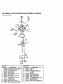
RAFTSMAN 4-CYCLE ENGINE MODEL NUMBER: 143.981001
lrburetor No.640054
@"-37
_'-,37
I
"-
r2
f
;tEF. PART
!O. iNO.
)
10
I4
15
16
t7
640054
631776A
631970
631776
650506
632112
632174
630735
632164
650417
18
__0
20A
_5
630766
640016
640053
631951
)
REF
PART NAME
Carburetdr '(incl 184 on engine)
Throttle Shaft & Lever Ass'y.
Throttle Retum Spring
Throtter Shutter
Shutter Screw
Choke Shaft & Lever Assy
Choke Shutter
Choke Positioning Spring
Fuel Fitting
Throttle Crack Screw/Idle
Speed Screw
TensionSpring
Idle Restrictor Screw
Idle Restsfictor Screw Cap
Float Bowl Assy (tncl 32&33)
PART
N_, No.,
27
28
29
30
63t 024
632019
631028
631021
31
32
33
36
37
40
44
47
48
631022
27136A
27554
640005
632547
640012
27110
630748
631027
PART NAME
Float Shaft
Float
Float Bowt "O" Ring
Inlet Needle, Seat & Clip
(lnc131)
SpringClip
Bowl Drain Assembly
Drain Plunger Gasket
Main Nozzle Tube
"O" Ring, Main Nozzle Tube
High Speed Bowl Nut
Bowl Nut Washer
Welch Plug, Idle Mixture Well
Welch Plug, Atmospheric Vent
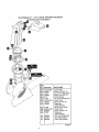
CRAFTSMAN
30'_- '11H.P. SNOW THROWER
536.886220
REMOTE CHUTE ASSEMBLY
4
A
i
REF.
NO,
965
966
967
968
969
970
971
972
975
990
991
992
993
995
996
PART NO.
780207
120385
310088
120393
46931
180077
780066
1498
761129
122168
120394
4051
578659
578293
71046
PART NAME
Spring, Tension
Washer, Flat
Bolt, t/4-20
Flatwasher, 344x.69x.065
Nut, 1/4-20
Screw, 5/16-18X °75
Bracket, Cable Chute
Nut, 5/16,.18 Reghxctrlk
Cable, Chute Control
Screw, 3/8-16 x 1.75
Washer, Flat
Washer, Spring
Lever, Chute
Knob, 1.5 Diameter
Nut, 3/8-16
343076B
35
CRAFTSMAN
30" - 11H.P, SNOW THROWER
CHUTE CONTROL ROD ASSEMBLY
36
536.886220
CRAFTSMAN
30" - 11H°Po SNOW THROWER
536.886220
CHUTE CONTROL ROD ASSEMBLY
REF_
NO.
PART NO.
850
851
578295
71072
852
853
854
855
856
857
858
859
121222
578051
578043
1795
73664
578044-853
180077
120393
860
861
862
864
71038
761099
30289
761066-853
867
868
872
873
874
875
676
677
339560
55023
578063
578309
578060
579493
585195
585196
PART NAME
Rod, Assy Upper Chute
Flatwasher
406X .81X.066
Cotter Pin
Cover, Chute Crank
Handle
Retainer Cap 3/8
Nut, Push-on 3/6"
Bracket, Console
Screw, 5/164 8X ,75
Flatwasher
,344X ,69X,065
Nut, 5116-18 Hexnyl
Rod, Mid-Chute Assy
Wave Washer
Bracket, Lower Chute
Control
Rod ,Lower Chute Assy
Trim 77°5"
Block, Universal Pivot°
Clevis Pin
Pin, Universal Joint
Cotter Pin
Worm Bracket
Worm Gear
340866G
37
CRAFTSMAN
30" - 11H.P. SNOW THROWER
DECALS
536.886220
340893B
REF
NO. PART NO.
822
823
824
B25
828
827
828
8291
i833
38
760970
313892
70141
302922
760968
760967
761078
761095
760983
PART NAME
Decal, t2" Impeller
Decal, Danger Chute
Decal, Danger Foot
Decal, Danger
Decal, Craftsman
Decal, 11/30 ES
Decal, Danger Chute
Decal, Control Panel
Decal, Toolbox
CRAFTSMAN30"
- 1 '1H,P. SNOW THROWER
HANDLE ASSEMBLY
536.886220
340090K-2
REF.
NO.
PART NO.
770
339966
771
308313
772
300303
774
579440
780 578144-853
78t
122168
782
313842
783
120394
784
71046
785
73787
788
578292
790
121222
791
120393
792
760966
793
120368
795
120638
796
313841
811
579944
812
337436
813
71111
PART NAME
Consote
Plug
Screw, .25X75X.51
Screw, 1/4-20X ,50
Gear Selector Bracket
Screw. 3/8-16X1.75
Spring
Flatwasher ,406X .81X_065
Nut, 3/8-16 Hexnyl
FIatwasher
Knob, to50 DIA
Cotter Pin .090 DIAX _75LG
Fiatwasher ,344X ,69X,065
Shift Red
Nut. 5/16-24 Reghex
Washer, Hvsptlk.328Xo60X.09
Steel Bal! Joint
Bearing Flange
Rod, Assy Yoke "Panel"
Nut 3/8=16
CRAFTSMAN
3_
4-CYCLE ENGINE MODEL NUMBER: 143.981001
z_'T
19
_1
186
4_
;RAFTSMAN
:_ef.# I Part Noi
2
3
4
35371
27652
650820
31857
5
15
15A
15B
16
17
18.
19
20
25
26
28
30
35
36
37
38
40
40
40
41
41
41
42
42
42
43
45
47
48
49
50
50
55
69
70
71
75
90
91
82
83
84
86
87
89
90
92
93
100
101
102
103
110
110A
119
120
125
125
126
126
127
126
129
130
131
131A
t35
30969
1306990
30700
1650494
33454
129916
1651026
134663
135319
J36460
}650561
| 30322
136245A
J29626
|29916
1292t6
129642
|35776
135777
J35776
135773
|35774
135775
|35779
J35760
135781
135772
136896
1651033
134034
136896
135375
I33273A
|650128
_35262A
}35376
J35377
]35319
131845
130590A
135378
|30588A
|29193
|650833
|650832
|32589
1611193
1650860
1650861
i35135
1610118
1651024
1651007
135187
137047
136451
136449
127878A
127680A
134035
|34036
{650691
|650690
|650727
|6021A
|650694A
_650713
|35395
t39
|33369
140_650836
4-CYCLE
ENGINE
Description
! Cyiinder (incl 2 20 72)
! Dowel P{n
', Screw, 1/4-20xlt2"
! Oil Drain Extension
i Extension Cap
, Governor Rod (Inc115A & t58)
Governor Yoke
=
Screw 6-40 x 5/16
Governor Lover
Govemor Lover Clamp
ScrewT-15 6-32x318"
Speed Control Spring
Oil Seal
Blower Housing Baffle
Screw 1/4-20x5t8"
Loocknut 8-32
Crankshaft
=
Screw 10-32x314
Lockwashor
Locknut 10-32
Retaining Ring
Piston,Pin,&Ring Set(Std)
Piston,Ptn,&Rtng Set(-010:)
Piston,Ptn,&Ring Set{,020 )
Piston&Pin Assy(Std(Incl.43)
.
Piston&Pin Assy(o010. OS)(tnc143)
Piston&Pin Assy(.O20 OS(Inel. 43)
Ring Set (Std)
Ring Set (.010 = OS)
Ring Set (..020 'OS)
Piston Pin Retaining Ring
Connecting Rod Assy(tncl 47,49)
Connecting Rod Bolt
Vatve Lifter
Oil Dipper
Camshaft (MCR)
Blower Hsing Extension
Screw 10-24xl/2"
Cylinder Cover Gasket
Cylinder Cover (tncl 71,75,&80)
Crankshaft Bushing
Oil Sea_
Governor Shatt
Washer
Govemor Gear Assy.(tnc181)
Govemor Spool
Retaining Ring
Screw, 1/4-20xl-3116"
Screw 1/4-20xld 1/16
Flywheel Key
Flywhea_ (w/ring gear)
Lock Washer
Flywheel Nut
Softd State Ignition
Spark Plug Cover
Solid State Mttng Stud
Screw Torx T-15 10-24x15/16
Ground Wire
Ground Wire
Cylinder Head Gasket
Cylinder Heed
ExhaustyalL'e (std)!lnc1151)
Exhaust Vatve(1/32 OS)(inct I51)
Intake Valve {std)(!ncl. 15t)
Intake Valve (1/'32 OS)(tnc1151)
Washer
Belfeviflo Washer
Screw, 5/'16-18xl-3/'4"
Screw 5/'16-18x1-1/2
Screw, 5/'16-18 x2 .
Screw 5/16-16 x 5/'8
Resistor Spark Ptug(RJ19LM)
Governor Gear Bracket
Screw
10-24xlt2
MODEL
NUMBER:
143.981001
Ref.#
Part No.
149
149A
150
151
t69
170
171
172
I73
t74
178
182
183
184
185
166
t868
200
27862
35662
27881
32561
27896A
28423
28424
28425
35350
650126
29752
30088A
34587A
33263
33677
34667
36652
34677
Valve Spring (
Valve Spdng (
Valve Spring
Valve Sprlng]
_or
Valve Cover C
et
Breather Bod
Breather Elerr
Valve Cover
Breather Tub_
Screw 10-24
t/'2"
Nut & Lock Washer 1t4-28"
Screw, 1/4-28
ChokeBraeke
Carburetor To _take Pine Gskt
intake P_pe
Governor Lin_
Choke Spring
Control Bkt (tncL 203.204)
203
31342
204
651029
208
610973
207
33878
209
650821
215
35440
219
34586
_20
35438
222
25620
223
650378
224
27915A
260
35447A
26t
650786
262
297478
264A 650602
265
332728
275
35056
276
31586
277
651002
28t
33013
282
_50760
265
359858
267
29752
290
30705
292
26460
298
650665
300
34156A
301
35355
305
35554
307
35499
306
35540
Compression Spring
.
Screw, T-10 5-40x7/16
Terminal
Throttle Unk
Screw 10-32
1/2=
Control Knob
Choke Rod
Choke Knob
Screw 10-32
I/2"
Screw Torx 1"5/'! 6-t8x1-1/8"
Intake Pipe Gasket
Blower Housi_
Screw 5/16-1E
Screw Torx 1".
5/'16-24x21/32'
Screw, 1/4-20
Cylinder Hoa_
:_ver(BIack)
Muffier
Locking Plate
Screw 5116-1E
8"
Starter BubbS_ _ver
Screw 8-32x3,
Starter Cup
Nut & Lock w_
1/'4-28
Fuel Line
Fuel Line Clar _p
Screw 1/4d5:
If4'
Fuel Tank (Inci 292 & 301)
Fuel Cap
Oil Fi]t Tube
"O" Ring
Fill Tube Ciip
310
36205
314
650973
315
!611111
1323 i611118
325
29443
327
35392
328
35593
329
1610973
335
35057A
336
i650765
338
28942
340:34154
341
i34155
342
650561
350
;570682
351
!32160C
355
590574
364
33377
365
:,650767
370
36261
3708 i35077
370C 36501
3701 35878
380
640054
390
590733
396
33329D
Dipstick
Screw 1/4-20 x 3/'4
Allemator Coi{(18 Watt)(lnc1323)
Terminal
Wire Clip
Starter Plug
Ignttton Key
Terminal
Carburetor Co
Screw 10-32x'/'2"
Screw 10-32x3/8"
FuelTank Bracket
FueI Tank Bracket
Screw 1/4-20x ;/8"
Primer Bulb
Primer Line
Starter Handi_ (Mitten Grip)
Carburetor Co
tracker
Screw 8-32x2_/64"
Identification [
Control Decal
Primer Decal
Wamfng Deca
Carburetor (In,
184)
Rewind StarVe
Electric Starts Motor Kit
(Optional)
Gasket Set
400
36452A
Desc iptton
CRAFTSMAN
4-CYCLE ENGINE MODEL NUMBER: 143.981001
Starter No. 590733
!1
_,-._w
11
12
PART
NO.
590733
590599A
590600
590696
590601
590697
590698
590699
590709
590734
590535
13
590574
iREF,
_NO.
_0
1
i2
i3
4
5
6
i7
is
_i _
PART NAME
RewindStarter
SpringPin (lncL4)
Washer
Retainer
Washer
Brake Spring
Starter [Jog
Dog Spring
Pulley & Rewind Sprg Assy
Starter HousingAssy
Starter Rope
(Length 96"x9/64" dta)
Mitten Grip Handle(not
included with starter)
42
,RAFTSMAN
4-CYCLE ENGINE MODEL NUMBER:
143.981001
;tarter Noo590749
I
REF,
NO.
0
1
2
3
4
5
6
;;7
181
12
13
PART
,,N(3,
590749
590599A
590600
590679
590601
590678
590680
590412
590682
590750
590535
590574
PART NAME
Rewind Starter
SpringPin (IncL 4)
Washer
Retainer
Washer
Brake Spring
Starter Dog
Dog Spring
Pulley & Rewind Spring Assy,
Starter Housing Ass y;
.
Starter Rope (Ig|h 98 x9/64 )
Mitten Grip Handle (Not included with starter)
43
For the repair or replacement parts you
need delivered directly to your home
Call 7 am-7 pm, 7 days a week
1-800-366-PART
(1-800-366-7278)
Para ordenar piezas con entrega
a domicilio -1-800-659-7084
For in-house major brand repair service
Call 24 hours a day, 7 days a week
1-800-4-REPAIR
(1-800-473-7247)
Para pedir servicio de reparaci6n a
domicilio - 1-800-676-5811
For the loCation of a Sears Parts and
Repair Center in your area
Call 24 hours a day, 7 days a week
1-800-488-1222
For information on purchasing a Sears
Maintenance Agreement or to inquire
about an existing Agreement
Call 9 am -5pm, Monday-Saturday
1-800-827-6655
When requesting service or ordering
parts, always provide the following
information:
- Product Type
• Part Number
• Model Number
• Part Description
Sm/ R8
America's
Repair
Specialists
Printed in U_S.A.