1
Installation Manual
•
•
•
•
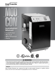
Installation
Startup
Maintenance
Parts
Models
MODCON VWH 300 / LP / HL / LPHL
MODCON VWH 500 / LP / HL / LPHL
MODCON VWH 850 / LP / HL / LPHL
n WARNING
This manual must only be used by a qualified heating installer/service technician. Read all instructions
in this manual before installing. Perform steps in the order given. Failure to comply could result in
severe personal injury, death or substantial property damage.
NOTICE
Heat Transfer Products, Inc., reserves the right to make product changes or updates without
notice and will not be held liable for typographical errors in literature.
GAS-FIRED HOT WATER SUPPLY BOILER
Boiler Manual
WARNING
If the information in this manual is not followed
exactly, a fire or explosion may result causing
property damage, personal injury or loss of life.
•
•
•
1
Do not store or use gasoline or other flammable
vapors and liquids in the vicinity of this or any
other appliance.
WHAT TO DO IF YOU SMELL GAS
Do not try to light any appliance.
gas supplier's instructions.
Do not touch any electrical switch:
• If you cannot reach your gas
do not use any phone in your
supplier, call the fire department.
building.
Installation and service must be
performed by a qualified installer,
Immediately call your gas supplier
service agency or the gas supplier.
from a neighbor's phone. Follow the
GAS-FIRED HOT WATER SUPPLY BOILER
Boiler Manual
CONTENTS
Part 1 – Product and Safety Information . . . . . . . . . . . . . . . . . . . . . . . . . . . . . . . . . . . . . . . 4
Part 2 – Before You Start . . . . . . . . . . . . . . . . . . . . . . . . . . . . . . . . . . . . . . . . . . . . . . . . . . . 6-8
Mod Con Recovery Ratings
Mod Con VWH Recovery Ratings with Storage Tanks
A. What’s In The Box
B. How The Boiler Operates
C. Optional Equipment
Part 3 – Prepare Boiler Location . . . . . . . . . . . . . . . . . . . . . . . . . . . . . . . . . . . . . . . . . . . . 8-13
A.
B.
C.
D.
E.
F.
G.
Boiler Location / Dimensions
Installations Must Comply With:
Before Locating the Boiler
Clearances for Service Access
Exhaust Vent and Intake Air Vent
Prevent Combustion Air Contamination
When Removing a Boiler from an Existing Common Vent System
Part 4 – Prepare Boiler . . . . . . . . . . . . . . . . . . . . . . . . . . . . . . . . . . . . . . . . . . . . . . . . . . . 13-14
Part 5 – Boiler Piping . . . . . . . . . . . . . . . . . . . . . . . . . . . . . . . . . . . . . . . . . . . . . . . . . . . . 14-27
A.
B.
C.
D.
E.
F.
G.
H.
Relief Valve
General Piping Information
System Water Piping Methods
Circulator Pumps
Installation of Flow Switch
Scalding
High Velocity Circulator Pump
Boiler Piping Details
Part 6 – Venting, Combustion Air & Condensate Removal . . . . . . . . . . . . . . . . . . . . . . 28-38
A.
B.
C.
D.
E.
F.
G.
H.
I.
J.
Installing Exhaust Vent and Intake Air Vent
General
Approved Materials for Exhaust Vent and Intake Air Vent
Exhaust Vent and Intake Air Vent Pipe Location
Exhaust Vent and Intake Air Vent Sizing
Longer Vent Runs
Exhaust Vent and Intake Air Pipe Installation
Heater Removal from a Common Vent System
Diagrams for Sidewall Venting
Diagram for Vertical Venting
Part 7 – Gas Piping. . . . . . . . . . . . . . . . . . . . . . . . . . . . . . . . . . . . . . . . . . . . . . . . . . . . . . 39-43
A.
B.
C.
D.
E.
Gas Connection
Gas Piping
Gas Table
Check Inlet Gas Pressure
Dungs Gas Valve
2
GAS-FIRED HOT WATER SUPPLY BOILER
Boiler Manual
CONTENTS (CONT’D)
Part 8 – Field Wiring. . . . . . . . . . . . . . . . . . . . . . . . . . . . . . . . . . . . . . . . . . . . . . . . . . . . . . 44-51
A.
B.
C.
D.
E.
F.
G.
H.
I.
J.
K.
L.
M.
N.
Installation Must Comply With
Field Wiring Terminations
Field Wiring Considerations
Line Voltage Wiring for ModCon VWH
Alarm Connections
Low Voltage Connections for Standard Boiler
Tank Sensor or Mechanical Control
System/Pipe Sensor
Optional High Gas Pressure Switch
Optional Low Gas Pressure Switch
Flow Switch
Wiring of Cascade System Communication Bus
ModCon VWH Cascade Master Pump and Sensor Wiring
ModCon VWH Cascade Follower Pump and Sensor Wiring
Part 9 – Start Up Preparation . . . . . . . . . . . . . . . . . . . . . . . . . . . . . . . . . . . . . . . . . . . . . 52-54
A.
B.
C.
D.
E.
F.
Single Mod Con VWH Boiler
Multiple Mod Con VWH Boilers
Check for Gas Leaks
Condensate Removal
Final Checks Before Starting Boiler
Cascade System
Part 10 – Start-Up Procedure . . . . . . . . . . . . . . . . . . . . . . . . . . . . . . . . . . . . . . . . . . . . . 55-57
A.
B.
C.
D.
Operating Instructions
Adjusting the Operating Set Points of the VWH Display
Status Menu
Test Mode
Part 11 – Start-Up Procedures for the Installer. . . . . . . . . . . . . . . . . . . . . . . . . . . . . . . 57-59
A. Programming for the Installer
B. Program Access
C. Program Navigation
Part 12 – Troubleshooting. . . . . . . . . . . . . . . . . . . . . . . . . . . . . . . . . . . . . . . . . . . . . . . . 60-63
A. Mod Con Error Code
B. Boiler Error
C. Boiler Fault
Part 13 – Maintenance. . . . . . . . . . . . . . . . . . . . . . . . . . . . . . . . . . . . . . . . . . . . . . . . . . . 63-78
A. Maintenance Procedures
B. Combustion Chamber Coil Cleaning Instructions for the Mod Con
C. Maintenance Procedure to Clean Heat Exchanger
Inspection and Maintenance Start-Up Charts
3
Boiler Manual
GAS-FIRED HOT WATER SUPPLY BOILER
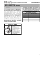
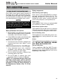
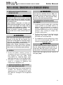
PART 1: PRODUCT AND SAFETY INFORMATION
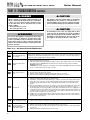
SPECIAL ATTENTION BOXES
The following defined terms are used throughout this manual to bring attention to the presence of
hazards of various risk levels or to important information concerning the product.
DEFINITIONS
n DANGER
n CAUTION
DANGER indicates an imminently hazardous
situation which, if not avoided, will result in
death or serious injury.
CAUTION Indicates a potentially hazardous
situation which, if not avoided, may result in
minor or moderate injury.
n WARNING
CAUTION
WARNING indicates a potentially hazardous
situation which, if not avoided, could result in
death or serious injury.
CAUTION used without the safety alert symbol
indicates a potentially hazardous situation which,
if not avoided, may result in property damage.
This appliance must be installed by qualified and licensed personnel in accordance with
local codes, or in the absence of local codes, by the national fuel gas code, ANSI Z223.12002. This appliance is for indoor installations only. Clearance to combustible materials: 0”
top, bottom, sides and back. Front must have room for service, 24” recommended. (A
combustible door or removable panel is acceptable front clearance.) This appliance has
been approved for closet installation. Do not install this appliance directly on carpeting. For
installation on combustible flooring directly. Category IV vent systems only.
4
Boiler Manual
GAS-FIRED HOT WATER SUPPLY BOILER
PART 1: PRODUCT AND SAFETY INFORMATION (CONT’D)
n WARNING
CAUTION
You must not have a direct connection of the
potable water system into the Mod Con VWH heat
exchanger which could cause flow issues, short
cycling and increase mineral build-up in the unit.
The Mod Con VWH System is designed to have the
incoming potable water flow through the storage
tank first and then flow from the storage tank
through the Mod Con heat exchanger. Failure to
pipe the Mod Con VWH properly will void
warranty.
Installer — Read all instructions in this manual,
and Mod Con Venting section, before installing.
Perform steps in the order given.
User — This manual is for use only by a
qualified heating installer/service technician.
Refer to User’s Information Manual for your
reference.
User — Have this boiler serviced/inspected by
a qualified service technician annually.
Failure to comply with the above could result in
severe personal injury, death or substantial
property damage.
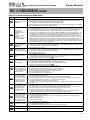
BEFORE INSTALLING
WHEN SERVICING BOILER
n WARNING
•
To avoid electric shock, disconnect electrical
supply before performing maintenance.
Failure to adhere to the guidelines on this page
can result in severe personal injury, death or
substantial property damage.
•
To avoid severe burns, allow boiler to cool
before performing maintenance.
BOILER OPERATION
n WARNING
WHAT TO DO IF YOU SMELL GAS
• Do not try to light any appliance.
• Do not touch any electric switch; do not use
any phone in your building.
• Immediately call your gas supplier from a
neighbor's phone. Follow the gas suppliers'
instructions.
• If you cannot reach your gas supplier, call the
fire department.
•
Do not block flow of combustion or
ventilation air to boiler.
•
Should overheating occur or gas supply fail to
shut off, do not turn off or disconnect electrical
supply to circulator. Instead, shut off the gas
supply at a location external to the appliance.
•
Do not use this boiler if any part has been
under water. Immediately call a qualified
service technician to inspect the boiler and to
replace any part of the control system and
any gas control that has been under water.
CAUTION
Consider piping and installation when
determining boiler location.
5
Boiler Manual
GAS-FIRED HOT WATER SUPPLY BOILER
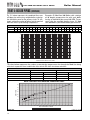
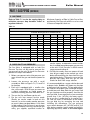
PART 2: BEFORE YOU START
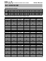
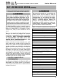
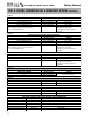
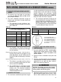
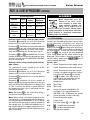
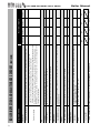
MODCON RECOVERY RATINGS
WATER FLOW AT VARIOUS TEMPERATURE RISE
20Δt 25Δt 30Δt 35Δt 40Δt 45Δt 50Δt 55Δt 60Δt 65Δt 70Δt 75Δt 80Δt 85Δt 90Δt 95Δt 100Δt 105Δt 110Δt 115Δt 120Δt 125Δt 130Δt 135Δt 140Δt
Model
RECOVERY RATE IN GALLONS PER HOUR BASED ON TEMPERATURE RISE BETWEEN INLET TEMPERATURE AND OUTLET TEMPERATURE
ModCon 300 1,692 1,354 1,128 967
564
521
483
451
423
398
376
356
338
322
308
294
282
271
260
251
242
ModCon 500 2,820 2,256 1,880 1,611 1,410 1,253 1,128 1,025 940
846
752
677
615
868
806
752
705
664
627
596
564
537
513
490
470
451
434
418
403
ModCon 850 4,794 3,835 3,196 2,739 2,397 2,131 1,918 1,743 1,598 1,475 1,370 1,278 1,199 1,128 1,065 1,009 959
913
872
834
799
767
738
710
685
MODCON VWH RECOVERY RATINGS WITH STORAGE TANKS
ModCon 300 VWH
Inlet
Temperature
Outlet
Temperature
40°
40°
40°
40°
40°
40°
40°
40°
40°
40°
40°
80°
90°
100°
110°
120°
130°
140°
150°
160°
170°
180°
Inlet
Temperature
Outlet
Temperature
40°
40°
40°
40°
40°
40°
40°
40°
40°
40°
40°
80°
90°
100°
110°
120°
130°
140°
150°
160°
170°
180°
Inlet
Temperature
Outlet
Temperature
40°
40°
40°
40°
40°
40°
40°
40°
40°
40°
40°
80°
90°
100°
110°
120°
130°
140°
150°
160°
170°
180°
Recovery Gallons First Hour Rating First Hour Rating First Hour Rating
Per Hour
With 80 Gallon With 119 Gallon With 175 Gallon
846
677
564
483
423
376
338
308
282
260
242
906
737
624
543
483
436
398
368
342
320
302
935
766
653
572
512
465
427
397
371
349
331
971
802
689
608
548
501
463
433
407
385
367
ModCon 500 VWH
Recovery Gallons First Hour Rating First Hour Rating First Hour Rating
Per Hour
With 80 Gallon With 119 Gallon With 175 Gallon
1,410
1,128
940
806
705
627
564
513
470
434
403
1,470
1,188
1,000
866
765
687
624
573
530
494
463
1,499
1,217
1,029
895
794
716
653
602
559
523
492
1,535
1,253
1,065
931
830
752
689
638
595
559
528
ModCon 850 VWH
Recovery Gallons First Hour Rating First Hour Rating First Hour Rating
Per Hour
With 80 Gallon With 119 Gallon With 175 Gallon
2,397
1,918
1,598
1,370
1,199
1,065
959
872
799
738
685
2,457
1,978
1,658
1,430
1,259
1,125
1,019
932
859
798
745
2,486
2,007
1,687
1,459
1,288
1,154
1,048
961
888
827
774
2,522
2,043
1,723
1,495
1,324
1,190
1,084
997
924
863
810
6
Boiler Manual
GAS-FIRED HOT WATER SUPPLY BOILER
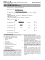
PART 2: BEFORE YOU START (CONT’D)
Min Tank Size (gal.) = Required flow (GPM) x 10
Mixing factor M f = VWH Outlet Temp– 40
70
First Hour rating =
[
Total VWH Output x VWH Efficiency
(VWH Outlet Temp-40) x 8.31
+.75 x Total Storage
]
x
Mf
Example:
2 MOD CON VWH 500 Total Output = 1,000,000 BTU @ 94% Efficiency
VWH Outlet Temp 140 °F
2 Storage Tanks (80 Gallon Each) Total Storage = 160 Gallons
Mixing factor Mf = 140-40 = 1.43
70
First Hour rating =
First Hour rating =
First Hour rating =
First Hour rating =
[
[
[
[
1,000,000 x .94
(140-40) x 8.31
+.75 x 160
940,000
831
+ 120
1,131
+ 120
1,251
]
]
]
]
x
1.43
x
1.43
x
1.43
x
1.43
First Hour rating = 1789 Gallons
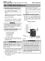
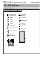
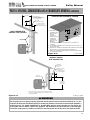
A. WHAT’S IN THE BOX
Also included with the Mod Con are:
•
•
•
•
•
•
•
•
•
•
Pressure and Temperature Gauge
Installation Manual
Warranty
CSD-1 Form
H-3 Data Sheet
Intake/Exhaust Screen
Supply and Return Thermistors
Flow Switch and Fitting
Wiring Harness
System/Pipe Sensor
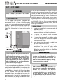
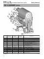
B. HOW BOILER OPERATES
Mod/Con Condensing Technology is an intelligent system that delivers highly efficient hot
water heating, while maximizing efficiency by
measuring the data parameters of your connected storage tank. Outlined below are the features
7
of the system and how they operate:
1. Stainless Steel Heat Exchanger – The highly
efficient Mod/Con Stainless Steel Heat
exchanger is designed to use the cold return
water from the system and extract the last bit
of heat before it is exhausted.
2. Modulating Combustion System – The
combustion system will modulate the output
of the burner during operation to match the
system demand and achieve the control set
point while in operation. The set point can
change by internal or external signals which
enhance the overall performance of the
system.
3. Control – The integrated control system
monitors the system and regulates the fan
speed to control the boilers output. This
allows the boiler to deliver only the amount
of heated energy required and nothing more.
The control can regulate the output of
multiple boilers through its cascade system
function.
GAS-FIRED HOT WATER SUPPLY BOILER
Boiler Manual
PART 2: BEFORE YOU START (CONT’D)
4.
5.
6.
7.
8.
9.
10.
11.
12.
13.
The cascade system is capable of connecting
up to eight boilers together in such a way that
they function as one boiler system. This
allows for greater turn down ratios and
provides systematic control of the multiple
boilers in an installation to minimize
downtime and maximize efficiency.
The cascade system works by establishing
one boiler as the master and the other
connected boilers as followers.
System Display and Operation Led light
Indicators – The display allows the user to
change the system parameters and monitor
the system outputs. Led light indicators
monitor system operation .
Gas Valve – The gas valve senses suction
from the blower allowing gas to flow only if
the gas valve is powered and combustion air
is flowing.
Swirl Plate or Venturi – Controls the air and
gas flow into the burner.
Burner – Constructed of high grade stainless
steel, the burner uses premixed air gas and
provides a wide range of firing rates.
Spark Ignition – The burner is ignited by
applying a high voltage through the system
spark electrode. This causes the spark from
the electrode to ignite the mixed gas off of
the burner.
Supply Water Temperature Sensor – This
sensor monitors the boiler outlet water
temperature (System Supply). The control
adjusts the boiler firing rate so the supply
temperature will match the boiler set point.
Return Water Temperature Sensor – This
sensor monitors the boiler return water
temperature (System Return). The control
adjusts the boiler firing rate depending on
how close the return water temperature is to
the supply water temperature.
Temperature and Pressure Gauge – Allows
the user to monitor the system temperature
and pressure.
Electrical field connections with terminal
strips – The electrical cover allows easy
access to the line voltage and low voltage
terminals strips which are clearly marked to
facilitate wiring of the boiler.
Condensation Collection System – This boiler
is a high efficiency appliance, therefore the
boiler will produce condensate. The collection
system has a float switch to monitor the
condensate level to prevent condensate from
backing up into the combustion system. There
is a built in trap inside the collection system to
seal the combustion system from the
connected drain. The condensate should be
neutralized to avoid damage to the drainage
system or piping.
14. Flow Protection – The supplied flow switch is
designed to protect the boiler in the event of
low flow conditions. The boiler control will
also monitor the flow through the heat
exchanger by monitoring the return and
supply sensor and will shut down the burner
before overheating occurs.
15. System Pipe Sensor – The supplied System
pipe Sensor is designed to be used in a
Cascade System when the sensor is placed
on the supply line of multiple boilers that feed
the storage tank. This will control the
temperature and modulate the firing rate of
the connected boilers.
16. Indirect Tank Sensor (optional) – Used to
monitor tanks l temperature.
C. OPTIONAL EQUIPMENT
Below is the list of optional equipment available
for Mod Con Boiler.
• Indirect Tank Sensor (Part # 7250P-325)
• 4” Stainless Steel Outside Termination Vent
Kit (V2000)
• 6” Stainless Steel Outside Termination Vent
Kit (V3000)
• High and Low Gas Pressure Switch Kit with
Manual Reset (Part # 7350P-600)
• U.L. 353 Compliant Low Water Cut-Off
Interface Kit with Manual Reset (Part # 7350P601)
• Alarm System (Part # 7350P-602) (to monitor
any failure)
• Stacking Kit (Part # 7350P-603)
• PC Connection Kit (Part # 7250P-320)
• Boiler Caster Kit (Part # 7350P-604)
• Mod Con Condensate Neutralizer (Part #
7350P-611)
These additional options may be purchased
through your HTP Distributor.
8
GAS-FIRED HOT WATER SUPPLY BOILER
Boiler Manual
PART 3: PREPARE BOILER LOCATION
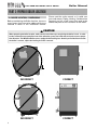
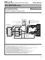
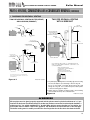
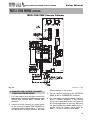
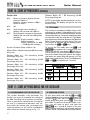
A. BOILER LOCATION / DIMENSIONS
Before considering the Boiler location, there are
many factors that have to be addressed that are
covered in detail in this installation manual.
Please read the entire manual as it could save
time and money. Piping, Venting, Condensation
Removal are just a few issues that need to be
addressed prior to the installation of the boiler.
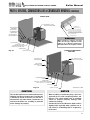
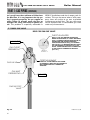
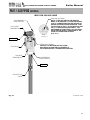
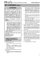
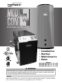
n CAUTION
When preparing the boiler location, make sure the area where you are placing the boiler is level. In order
for the condensate to properly flow out of the collection system, the boiler must be level to assure proper
flow direction. The Mod Con Boiler comes equipped with leveling feet. Should you find the floor beneath
the boiler is uneven, adjust the leveling feet with a wrench.
9
INCORRECT
CORRECT
INCORRECT
CORRECT
Boiler Manual
GAS-FIRED HOT WATER SUPPLY BOILER
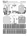
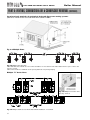
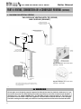
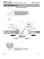
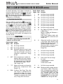
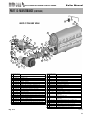
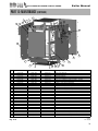
DIMENSIONS
FLOW SWITCH
LEFT SIDE
(MOD CON 300) POWER SWITCH
ACCESS PANEL
FRONT
(ALL MODELS)
RIGHT SIDE
(MOD CON 300)
DISPLAY PANEL
HOT WATER
OUTLET
ELECTRICAL BOX
K
A
L
F
N
G
B
GAS LINE
C
LEGS ADJUST
1-1/4"-3"
CONDENSATE
DISCHARGE
D
J
E
RIGHT SIDE
(MOD CON 500/850)
REAR
(ALL MODELS)
EXHAUST
AIR INTAKE
LEFT SIDE
(MOD CON 500/850)
ELECTRICAL BOX
ACCESS PANEL
M
VWH
MODEL
A
B
C
D
D
F
J
G
H
K
L
M
N
MOD CON
300*
20.00"
6.25"
10.25"
14.50"
26.00"
5.15"
35.75"
20.50"
36.00"
25.50"
8.25"
10.50
26.50
MOD CON
500*
20.00"
6.25"
13.25"
14.50"
33.30"
5.15"
41.75"
20.50"
36.00"
25.50"
8.25"
10.50
34.00
MOD CON
850*
20.00"
6.75"
16.25"
18.75"
43.50"
20.00"
66.75"
20.50"
36.00"
25.50"
8.25"
10.50
57.50
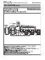
NOTE: ALL DIMENSIONS ARE APPROXIMATE AND HEIGHTS DO NOT INCLDE ADJUSTABLE LEGS.
*VWH DENOTES HOT WATER SUPPLY BOILER / LP DENOTES PROPANE / HL DENOTES HIGH/LOW GAS PRESSURE SWITCH.
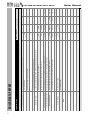
Gross
Output
BTU/hr
Net I=B=R
BTU/hr
Thermal
Efficiency
Boiler
Water
MOD CON 60,000-301,000
300*
283,000
245,000
94%
2.9
1-1/2"
MOD CON 100,000-500,000
500*
470,000
409,000
94%
4.2
MOD CON 170,000-850,000
850*
799,000
695,000
94%
5.8
VWH
MODEL
Figure 3-1
BTU/HR
INPUT
LOW FIRE
Vent
Dia.
Ship
Wt.
High
Fan
Speed
Low
Fan
Speed
Fan Speed
at Ignition
1-1/4"
4"
410
5500
1250
3000
2"
1-1/2"
4"
505
6930
1250
3000
2"
2"
6"
580
5400
1500
3000
Supply/Return Gas
Connection Conn.
LP-205-C Rev. 6/23/09
10
GAS-FIRED HOT WATER SUPPLY BOILER
Boiler Manual
PART 3: PREPARE BOILER LOCATION (CONTINUED)
B. INSTALLATIONS MUST COMPLY WITH:
•
Local, state, provincial, and national codes,
laws, regulations and ordinances.
•
National Fuel Gas Code, ANSI Z223.1 – latest
edition.
•
Standard for Controls and Safety Devices for
Automatically Fired Boilers, ANSI/ASME
CSD-1, when required.
•
National Electrical Code.
•
For Canada only: B149.1 or B149.2
Installation Code, CSA C22.1 Canadian
Electrical Code Part 1 and any local codes.
•
•
•
Incorrectly-sized expansion tank.
Boiler is located in a condition that could
cause the system and boiler to freeze and
leak.
Clean and flush system when re-installing
a boiler.
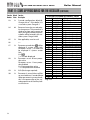
D. CLEARANCES FOR SERVICE ACCESS
1. See Figure 3-1 for recommended service
clearances. If you do not provide minimum
clearances shown, it might not be possible to
service the boiler without removing it from
the space.
SERVICE CLEARANCES
NOTICE
The Mod Con Boiler gas manifold and controls
met safe lighting and other performance criteria
when the boiler underwent tests specified in
ANSI Z21.13 — latest edition.
C. BEFORE LOCATING THE BOILER
1. Check for nearby connections to:
• System water piping
• Venting connections
• Gas supply piping
• Electrical power
• Condensate drain
2. Check area around boiler. Remove any
combustible materials, gasoline and other
flammable liquids.
n WARNING
Failure to keep boiler area clear and free of
combustible materials, gasoline and other
flammable liquids and vapors can result in
severe personal injury, death or substantial
property damage.
3. T h e M o d C o n G a s C o n t r o l S y s t e m
components must be protected from dripping
water during operation or service.
4. If the Mod Con Boiler is to replace an existing
boiler, check for and correct any existing
system problems such as:
• System leaks.
11
RQO\
Figure 3-1
LP-205-M Rev. 5/27/08
n WARNING
The space must be provided with combustion/ventilation air openings correctly sized for
all other appliances located in the same space as
the Mod Con Boiler. The boiler cover must be securely fastened to the boiler to prevent the boiler from drawing air from inside the boiler room.
This is particularly important if the boiler is located in the same room as other appliances.
Failure to comply with the above warnings could
result in severe personal injury, death or substantial property damage.
Boiler Manual
GAS-FIRED HOT WATER SUPPLY BOILER
PART 3: PREPARE BOILER LOCATION (CONTINUED)
n WARNING
E. EXHAUST VENT AND INTAKE AIR VENT
n WARNING
Vents must be properly supported. The Mod
Con’s Intake and Exhaust Connections are not
designed to carry heavy weight. Vent support
brackets must be within 1 foot of the boiler and
the balance at 4 foot intervals. The Mod Con
venting must be readily accessible for visual
inspection for the first three feet from the boiler.
The Mod Con Boiler requires a special vent system, designed for pressurized venting. Mod Con
Boilers are rated ANSI Z21.13 Category IV (pressurized vent, likely to form condensate in the
vent).
You must also install air intake piping from outdoors to the boiler flue adaptor. The resultant
installation is categorized as direct vent (sealed
combustion). Note: To prevent combustion
air contamination see Table 3-2 in this
section when considering exhaust vent
and intake air vent termination.
Intake and exhaust must terminate near each
other and may be vented vertically through the
roof or out a side wall. The intake and exhaust
venting methods are detailed in the Venting
Section. Do not attempt to install the Mod Con
Boiler using any other means. Be sure to locate
the boiler such that the air intake and exhaust
vent piping can be routed through the building
and properly terminated. The air intake and
exhaust vent piping lengths, routing and termination method must all comply with the methods
and limits given in the venting section.
F. PREVENT COMBUSTION AIR
CONTAMINATION
Install intake air piping for the Mod Con Boiler as
described in the Venting section. Do not terminate exhaust in locations that can allow contamination of intake air.
You must pipe outside air to the boiler air
intake. Ensure that the intake air will not
contain any of the contaminants below.
Contaminated air will damage the boiler,
resulting in possible severe personal injury,
death or substantial property damage. For
example, do not pipe intake air vent near a
swimming pool. Also avoid areas subject to
exhaust fumes from laundry facilities. These
areas will always contain contaminants.
Table 3-2: Corrosive contaminants and sources
Products to avoid
Spray cans containing fluorocarbons
Permanent wave solutions
Chlorinated waxes/cleaners
Chlorine-based swimming pool chemicals
Calcium chloride used for thawing
Sodium chloride used for water softening
Refrigerant leaks
Paint or varnish removers
Hydrochloric acid/muriatic acid
Cements and glues
Antistatic fabric softeners used in clothes dryers
Chlorine-type bleaches, detergents, and cleaning
solvents found in household laundry rooms
Adhesives used to fasten building products and
other similar products
Areas likely to have contaminants
Dry cleaning/laundry areas and establishments
Swimming pools
Metal fabrication plants
Beauty shops
Refrigeration repair shops
Photo processing plants
Auto body shops
Plastic manufacturing plants
Furniture refinishing areas and establishments
New building construction
Remodeling areas
Garages and workshops
12
GAS-FIRED HOT WATER SUPPLY BOILER
Boiler Manual
PART 3: PREPARE BOILER LOCATION (CONTINUED)
connected to the common venting system
are located and other spaces of the building.
Turn on clothes dryers and any appliance not
connected to the common venting system.
Turn on any exhaust fans, such as range
hoods and bathroom exhausts, so they will
operate at maximum speed. Do not operate
a summer exhaust fan. Close fireplace
dampers.
G. WHEN REMOVING A BOILER FROM AN
EXISTING COMMON VENT SYSTEM
n DANGER
Do not install the Mod Con Boiler into a common
vent with any other appliance. This will cause
flue gas spillage or appliance malfunction,
resulting in possible severe personal injury,
death or substantial property damage.
n WARNING
Failure to follow all instructions can result in flue
gas spillage and carbon monoxide emissions,
causing severe personal injury or death.
At the time of removal of an existing boiler, the
following steps shall be followed with each
appliance remaining connected to the common
venting system placed in operation, while the
other appliances remaining connected to the
common venting system are not in operation.
a. Seal any unused openings in the common
venting system.
b. Visually inspect the venting system for
proper size and horizontal pitch and
determine that there is no blockage or
restriction, leakage, corrosion or other
deficiencies which could cause an unsafe
condition.
c. Insofar as is practical, close all building doors
and windows and all doors between the
space in which the appliances remaining
d. Place in operation the appliance being
inspected. Follow the lighting instructions.
Adjust thermostat so appliance will operate
continuously.
e. Test for spillage at draft hood opening after 5
minutes of main burner operation. Use the
flame of a match or candle, or smoke from a
cigarette, cigar, or pipe.
f.
After it has been determined that each
appliance remaining connected to the
common venting system properly vents
when tested as outlined herein, return doors,
windows, exhaust fans, fireplace dampers
and any other gas-burning appliance to their
previous conditions of use.
g. Any improper operation of common venting
system should be corrected so the
installation conforms with the National Fuel
Gas Code, ANSI Z223.1 — latest edition.
Correct by resizing to approach the minimum
size as determined using the appropriate
tables in Table 13 of NFPA54 ANSI Z223.1
2006 of that code. Canadian installations
must comply with B149.1 or B149.2
Installation Code.
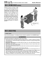
PART 4: PREPARE BOILER
n WARNING
CAUTION
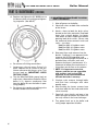
Uncrating Boiler – Any Claims for damage or
shortage in shipment must be filed immediately
against the transportation company by the
consignee.
Cold weather handling — If boiler has been
stored in a very cold location (below 0°F) before
installation, handle with care until the plastic
components come to room temperature.
Remove all sides of the Mod Con shipping crate
in order to allow the boiler to be lifted into its
installation location. You must pick the boiler up
by the lift rings to avoid damage to the boiler
13
GAS-FIRED HOT WATER SUPPLY BOILER
Boiler Manual
PART 4: PREPARE BOILER (CONTINUED)
enclosure. You can use either a solid
¾” in diameter black iron pipe or lifting straps to lift the boiler off of its
shipping crate. You must have at least
two individuals to handle the boiler
properly to avoid damage as care
should be taken as the Mod Con is
very heavy. The Mod Con is also
equipped with leveling feet that can
be used to level the boiler properly if
the surface location is not level. If surface flooring is rough, care should be
taken when sliding boiler into position, you could catch the leveling feet
and damage the boiler if it is slid to its
location.
,16(57%/$&.,5213,3(:,7+7((6
25/,)7,1*675$36
,172/,)7,1*5,1*63529,'('
$/:$<6/,)7:,7+$7/($673(23/(
/,)7,1*5,1*6
PART 5: BOILER PIPING
A. RELIEF VALVE
Connect discharge piping to a safe disposal location, follow the guidelines in the WARNING below.
n WARNING
To avoid water damage or scalding due to relief valve operation:
• Discharge line must be connected to relief valve outlet and run to a safe place of disposal. Terminate
the discharge line in a manner that will prevent possibility of severe burns or property damage should
the valve discharge.
• Discharge line must be as short as possible and be the same size as the valve discharge connection
throughout its entire length.
• Discharge line must pitch downward from the valve and terminate at least 6” above the floor drain
where any discharge will be clearly visible.
• The discharge line shall terminate plain, not threaded, with a material serviceable for temperatures of
375 °F or greater.
• Do not pipe the discharge to any place where freezing could occur.
• No shutoff valve shall be installed between the relief valve and boiler, or in the discharge line. Do not
plug or place any obstruction in the discharge line.
• Test the operation of the valve after filling and pressurizing system by lifting the lever. Make sure the
valve discharges freely. If the valve fails to operate correctly, replace it with a new relief valve.
• Failure to comply with the above guidelines could result in failure of the relief valve to operate,
resulting in possibility of severe personal injury, death or substantial property damage.
14
GAS-FIRED HOT WATER SUPPLY BOILER
Boiler Manual
PART 5: BOILER PIPING (CONTINUED)
B. GENERAL PIPING INFORMATION
n CAUTION
NOTICE
The Mod Con Boiler control module uses
temperature sensors to provide both high limit
protection and modulating temperature control.
The control module also provides low water
protection by sensing the water flow through
the flow switch on the heat exchanger. Some
codes/jurisdictions may require additional
external controls.
C. SYSTEM WATER PIPING METHODS
Expansion tank
1. Ensure that the expansion tank size will
handle boiler and system water volume and
temperature. Allow for boiler, piping and
storage tank:
Boiler Water Volume
Mod Con 300 VWH
2.9 Gallons
Mod Con 500 VWH
4.2 Gallons
Mod Con 850 VWH
5.8 Gallons
CAUTION
Undersized expansion tanks cause system
water to be lost from relief valve. Eventual
boiler failure can result due to excessive makeup water addition. This type of failure is NOT
covered by warranty.
2. The expansion tank must be located as
shown in Boiler Piping Part 5 or following
recognized design methods. See tank
manufacturer’s instructions for details.
Always install an expansion tank designed
for potable water systems.
15
D. CIRCULATOR PUMPS
DO NOT use the boiler circulator in any location
other than the ones shown in this manual. The
boiler circulator is selected to ensure adequate
flow through the Mod Con Boiler. Failure to
comply could result in unreliable performance
and nuisance shut downs from insufficient flow.
n WARNING
Plumbing of this product should only be done
by a qualified, licensed plumber in accordance
with all local plumbing codes.
The Mod Con VWH is designed to be connected
to a storage tank to supply domestic hot water.
Heat Transfer Products has available storage
tanks that are 80/119/175 gallon size storage
tanks constructed in either Stainless Steel or
Glass lined construction. These storage tanks will
be directly connected to the Mod Con VWH
supply and return connection. Connect the cold
water supply to both the storage bottom port and
the supply side of the Mod Con VWH (shown in
Piping details, this section) It is important that you
install a flow check on the supply line of Mod Con
VWH before you connect feed line to the storage.
This will allow the cold feed to flow through the
storage tank first and not the Mod Con VWH. It is
recommended that you install shut off valves on
the cold feed line for ease of future service. If
there is a back flow preventer, or any type of no
return valve in the system, then you must install
an additional tee for a suitable potable hot water
expansion tank. Connect the Storage tank return
line to the return connection located on the Mod
Con VWH (shown in Piping details, this section).
Then connect your hot water outlet located on
the storage tank to your hot water plumbing lines.
GAS-FIRED HOT WATER SUPPLY BOILER
Boiler Manual
PART 5: BOILER PIPING (CONTINUED)
n WARNING
2. Thread brass Tee into outlet nipple using pipe
dope:
Never use dielectric unions or galvanized steel
fittings when connecting to a stainless steel
storage tank or boiler.
n WARNING
When raising tank temperature, you increase
the risk of scalding – Please use a water
tempering or mixing valve and extreme caution.
Consult codes for conformance.
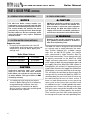
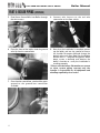
E. INSTALLATION OF FLOW SWITCH
Note: If you are converting the Mod Con boiler
to VWH you will follow steps 1-9. If you have
purchased a factory Mod Con VWH you will only
need fo follow steps 1, 2, 3 and 8.
3. Thread switch into Tee using pipe dope,
making certain the Flow Arrow points in the
correct direction:
1. Attach flow paddle as shown:
4. Disconnect red wire on the Low Water Cut off
Probe and connect it to the red wire from the
wire harness (included in kit):
16
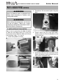
GAS-FIRED HOT WATER SUPPLY BOILER
Boiler Manual
PART 5: BOILER PIPING (CONTINUED)
5. Feed Green Ground Wire into Boiler through
the wire access:
8. Connect wire harness to the red wire
connection on the flow switch:
6. From the front of the boiler, feed the ground
wire Up into the control box:
9. Now that the installation is complete, power
up the boiler and use the control to access
the Installer Parameter #20 and change the
default value to 2 (See Mod Con Installation
Manual Part 11 – Program Navigation). When
done, create a demand and observe the
boiler’s function to verfiy the installation is
working proeprly.
*Please note that these illustrations are meant
to show system piping concept only, the
installer is responsible for all equipment and
detailing required by local codes.
7. Once into the control box, attached the green
ground to the ground bus connection
available:
17
GAS-FIRED HOT WATER SUPPLY BOILER
Boiler Manual
PART 5: BOILER PIPING (CONTINUED)
F. SCALDING
This water heater can deliver scalding temperature water at any faucet in the system. Be careful whenever using hot water to avoid scalding
injury. Certain appliances such as dishwashers
and automatic clothes washers may require
increased temperature water. By setting the
thermostat on this water heater to obatin the
increased temperature water required by these
appliances, you may create the potential for
scald injury. To protect against injury, you
should install a mixing valve in the water system. This valve will reduce point of discharge
temperature by mixing cold and hot water in
branch supply lines. Such valves are available
from the local plumbing supplier.
n
The following chart details the relationship of
water temperature and time with regard to scald
injury and may be used as a guide in determining
the safest water temperature for your applications.
APPROXIMATE TIME / TEMPERATURE
RELATIONSHIPS IN SCALDS
120°F
More than 5 minutes
125°F
1 1/2 to 2 minutes
130°F
About 30 seconds
135°F
About 10 seconds
140°F
Less than 5 seconds
145°F
Less than 3 seconds
150°F
About 1 1/2 seconds
155°F
About 1 second
DANGER
HOT
BURN
Water temperature over 125°F can
cause sever burns instantly or death
from scalds.
Children, disabled and elderly are at
highest risk of being scalded.
See instruction manual before setting
temperature at heating appliance.
Feel water before bathing or
showering.
If this appliance is used to produce
water that could scald if too hot,
such as domestic hot water use,
adjust the outlet control (limit) or
use temperature limiting valves to
obtain a maximum water
temperature of 125°F.
Figure 5-3 Scald Warning Label Located on the Appliance
18
Boiler Manual
GAS-FIRED HOT WATER SUPPLY BOILER
PART 5: BOILER PIPING (CONTINUED)
Fig. 5-1 below represents the combined flow rates
and pipe sizes when using multiple boilers to design
the manifold system for the primary circuit. To size,
simply add up the number of boilers and the required
flow rates for the system design temperature.
Flow rate 30 50 60 85
Pipe Dia. 2” 2½” 2½” 3”
Example: (5) Mod Con 300 Boilers with a design
of 30 degree temperature rise with each boiler
having an individual flow rate of 20 GPM. To correctly size the manifold feeding these (5) Mod
Con 300 Boilers you would need a pipe size of 3”.
MULTIPLE BOILER MANIFOLD PIPING
90 100 120 150 170 180 200 210 240 250 255 300 340 350 400 425 510 595 680
3” 3” 4” 4” 4” 4” 4” 4” 5” 5” 5” 5” 5” 5” 5” 5” 6” 6” 6”
Multiple Boiler Manifold Piping
7
Pipe Diameter Size (Inches)
6
5
4
3
2
1
0
0
100
200
300
400
500
600
700
800
Combined Boiler Water Flow (GPM)
Figure 5-1
The chart below represents the various system design temperature rise through the Mod Con along
with their respective flows and friction loss which will aid in circulator selection.
SYSTEM TEMPERATURE RISE CHART
20°Δt
25°Δt
Friction Feet
Flow G P M
Friction Feet
Flow G P M
19’
30
12’
24
19’
50
11’
40
35’
85
26’
65
Model
Mod Con 300 VWH
Mod Con 500 VWH
Mod Con 850 VWH
FRICTION IN FEET OF HEAD
MOD CON HEAT EXCHANGER PRESSURE DROP
90
80
70
FLOW OF GPM
60
50
40
30
20
10
0
2
4
6
8
10
12
14
16
18
20
22
24
26
28
30
32
34
36
FRICTION IN FEET OF HEAD
MODCON 300
Figure 5-2
19
MODCON 500
MODCON 850
LP-205-E Rev. 12/5/07
GAS-FIRED HOT WATER SUPPLY BOILER
Boiler Manual
PART 5: BOILER PIPING (CONTINUED)
G. HIGH VELOCITY CIRCULATOR PUMP
Every VWH system requires special attention to
the pump size in order to overcome the pressure drop through the boiler and its related piping. All circulators installed on the VWH system
must be designed for a potable water system.
NOTICE
Water temperature above 140° requires the
circulator pump to run continuously and must have a
water hardness of between 5 to 7 grains. Hardness
above 7 grains will damage the heat exchanger and
shorten the service life of the boiler.
Piping components
Water heating system piping:
Water heater system piping MUST be sized per
tech pipe requirements listed in Fig. 5-1 / 5-2.
Reducing the pipe size can restrict flow rate
through the water heater, causing inadvertent
short cycling and poor system performance.
Check valves:
Field supplied. Check valves are recommended
for installation as shown in Piping Details.
Water heater isolation valves:
Water chemistry*
Water pH between 6.0 and 8.0
Field supplied. Full port ball valves are required.
Failure to use full port ball valves could result in
a restricted flow rate through the water heater.
1. Maintain boiler water pH between 6.0 and 8.0.
Check with litmus paper or have it chemically
analyzed by water treatment company.
Anti-scald mixing valve:
2. If the pH differs from above, consult local water
treatment company for treatment needed.
Hardness less than 7 grains.
1. Consult local water treatment companies for
unusually hard water areas (above 7 grains
hardness).
Chlorine concentration less than 200 ppm
1. Using chlorinated fresh water should be
acceptable since drinking water chlorine
levels are typically less than 5 ppm.
Field supplied. An anti-scald mixing valve is recommended when storing domestic hot water
above 115°F.
Unions:
Field supplied: Recommended for unit serviceability. DO NOT USE DIELECTRIC UNIONS!
ONLY BRASS OR STAINLESS STEEL.
Pressure relief valve:
Factory supplied on Mod Con VWH. The pressure relief valve is sized to ASME specifications.
Storage tank may require additional relief valves
depending on local codes.
2. Do not connect the boiler to directly heat
swimming pool or spa water.
3. Do not fill boiler or operate with water
containing chlorine in excess of 200 ppm.
*NOTE: It is recommended you clean heat
exchanger at least once a year to prevent
lime scale buildup. Follow the maintenance
procedure to clean the heat exchanger in
the Maintenance Section (Part 13 of this
manual).
20
GAS-FIRED HOT WATER SUPPLY BOILER
PART 5: BOILER PIPING (CONTINUED)
H. BOILER PIPING DETAILS
Piping Symbol Legend
circulator (open loop)
(w/ isolation flanges)
anti-scald rated
mixing valve
flow switch
pressure gauge
gate valve
pressure relief valve
(or P&T relief valve)
globe valve
ball valve
T/P
swing-check valve
spring-loaded check valve
temperature /
pressure gauge
union
vacuum breaker
hose bib / boiler drain
diaphragm-type
expansion tank
(for potable water)
Superstor Ultra
Storage Tank
Mod Con Boiler
21
Boiler Manual
GAS-FIRED HOT WATER SUPPLY BOILER
Boiler Manual
PART 5: BOILER PIPING (CONTINUED)
22
GAS-FIRED HOT WATER SUPPLY BOILER
PART 5: BOILER PIPING (CONTINUED)
23
Boiler Manual
GAS-FIRED HOT WATER SUPPLY BOILER
Boiler Manual
PART 5: BOILER PIPING (CONTINUED)
24
GAS-FIRED HOT WATER SUPPLY BOILER
PART 5: BOILER PIPING (CONTINUED)
25
Boiler Manual
Boiler Manual
GAS-FIRED HOT WATER SUPPLY BOILER
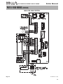
PART 5: BOILER PIPING (CONTINUED)
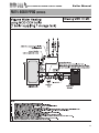
Drawing VWH 2/2 V MC
mechanical aquastat
(both tanks)
wired in series
(preferred)
cold water
recirculation line
ASEE 1017 rated anti-scald valve
(recommended)
hot water supply
Volume Water Heating
using MOD CON boilers
(2 boilers supplying 2 storage tanks)
System/Pipe Sensor
Used if sensor cannot be placed at tank –
(Important to note that Pumps must be
wired to run continuously to operate in
this configuration)
MOD
CON
vacuum breaker
(where required by code)
master
address = 0
MOD CON 1
flow switch
constant
circulation
MOD
CON
follower
address = 1
expansion
tank
Superstor Ultra
coil booster tank
Superstor Ultra
coil booster tank
required
system/
pipe
sensor
MOD CON 2
flow switch
condensate
drainage
NOTES:
1.
2.
3.
4.
5.
6.
7.
8.
9.
10.
11.
12.
13.
14.
15.
This drawing is meant to show system piping concept only. Installer is responsible for all equipment & detailing required by local codes.
Boiler circulator must be rated for open loop application. Do not use cast-iron circulators
Boiler circulator(s) operate continuously
The minimum pipe size for connecting to a water storage tank is 1.5 inch.
The minimum pipe size for connecting a MOD CON boiler is 1.5 inches for MOD CON 300 VWH, and 2-inches for MOD CON 500 & 800
All pumps are shown with isolation flanges or full port ball valves for isolation. The alternative is standard flanges
with full port ball valves and a separate flow check valve.
Install a minimum of 12 diameters of straight pipe upstream of all circulators and check valves.
Install vacuum relief valve in accordance with local code requirements
All multiple boilers and multiple storage tanks shall be installed with reverse return piping as shown
Anti-scald rated mixing valve is recommended on all tanks if the leaving hot water temperature from tank is above 119 °F.
Expansion tank must be rated for use with potable water
Use either a mechanical aquastat in each tank wired in series or system/pipe sensor shown. (Do not use both.)
Tank aquastats or pipe sensor connected to DHW sensor terminals on boiler addressed as #1.
The system/pipe sensor must be placed on common piping to the tank, as close to tank as possible.
The system/pipe sensor is wired to the system/pipe sensor terminals on the master boiler.
26
GAS-FIRED HOT WATER SUPPLY BOILER
PART 5: BOILER PIPING (CONTINUED)
27
Boiler Manual
GAS-FIRED HOT WATER SUPPLY BOILER
Boiler Manual
PART 6: VENTING, COMBUSTION AIR & CONDENSATE REMOVAL
A. INSTALLING EXHAUST VENT AND
INTAKE AIR VENT
n DANGER
n WARNING
Use only the materials listed in Tables 6-1
through 6-7 for the venting systems. Failure to
do so could result in severe personal injury,
death or substantial property damage.
The Mod Con Boiler must be vented as detailed
in this section. Ensure the exhaust and intake
piping comply with these instructions regarding
the venting system.
Inspect finished combustion air intake and
exhaust piping thoroughly to ensure all joints
are secure and airtight and comply with all
applicable code requirements, as well as with
the instructions provided in this manual.
Failure to provide a properly installed vent
system will cause severe personal injury or
death.
1. Installations must be made with a vent pipe
system certified to ULC-S636. IPEX is an
approved vent manufacturer in Canada in
Canada supplying vent material listed to
ULC-S636. Additionally you may use AL244C
stainless steel venting to comply with
Canadian requirements.
n WARNING
2. The first three (3) feet of vent pipe from the
appliance flue outlet must be readily
accessible for visual inspection.
This vent system will operate with a positive
pressure in the pipe. Do not connect vent
connectors serving appliances vented by natural
draft into any portion of mechanical draft
systems operating under positive pressure.
Follow these venting instructions carefully.
Failure to do so may result in severe personal
injury, death, or substantial property damage.
REQUIREMENTS FOR INSTALLATION
IN CANADA
3. The components of the certified vent system
must not be interchanged with other vent
systems or unlisted pipe / fittings.
n WARNING
Do not use Cellular Foam Core Pipe in any portion
of the exhaust piping from this boiler. Use of
Foam Core Pipe may result in severe personal
injury, death, or substantial property damage.
B. GENERAL
1. Install the boiler venting system in
accordance with these instructions and with
t h e N a t i o n a l Fu e l G a s C o d e , A N S I
Z223.1/NFPA 54, CAN/CGA B149, and/or
applicable provisions of local building codes.
Cellular foam core piping may be used on air
inlet piping only.
2. This boiler is a direct vent appliance and is
listed as a Category IV appliance with
Underwriters Laboratories, Inc.
C. APPROVED MATERIALS FOR EXHAUST
VENT AND INTAKE AIR VENT
1. Use only Non Foam Core venting material or
AL294C. The following materials are
approved for use as vent pipe for this boiler.
See Tables 6-1 through 6-7 for all approved
venting.
28
GAS-FIRED HOT WATER SUPPLY BOILER
Boiler Manual
PART 6: VENTING, COMBUSTION AIR & CONDENSATE REMOVAL (CONTINUED)
Table 6-1
APPROVED PLASTIC EXHAUST VENTING MATERIAL
STANDARDS FOR INSTALLATION IN:
UNITED STATES
CANADA
PVC SCHEDULE 40 / 80
ANSI /ASTM D1785
ULC S636**
PVC -DWV
ANSI /ASTM D2665
ULC-S636**
CPVC SCHEDULE 40 / 80
ANSI /ASTM F441
ULC- S636**
**Note: IPEX is an approved
*Note: Cellular Foam Core Pipe must only
Manufacturer in Canada
be used on INTAKE piping.
supplying vent material listed to
ULC-S636
MATERIAL
Table 6-2
APPROVED PLASTIC INTAKE VENTING MATERIAL
STANDARDS FOR INSTALLATION IN:
UNITED STATES
CANADA
ULC S636**
PVC SCHEDULE 40 / 80
ANSI /ASTM D1785
CPVC SCHEDULE 40 / 80
ANSI /ASTM F441
ULC- S636**
PVC DWV
ANSI /ASTM D2665
N/A
PVC-CELLULAR FOAM CORE*
U.L. LISTED
N/A
**Note: IPEX is an approved
*Note: Cellular Foam Core Pipe must only
Manufacturer in Canada
be used on INTAKE piping.
supplying vent material listed to
ULC-S636
MATERIAL
Table 6-3
APPROVED PLASTIC CONDENSATE PIPING MATERIAL
MATERIAL
STANDARDS FOR INSTALLATION IN:
UNITED STATES
CANADA
ANSI /ASTM D1785
ULC S636**
PVC SCHEDULE 40 / 80
**Note: IPEX is an approved
Manufacturer in Canada
supplying vent material listed to
ULC-S636
Table 6-4
APPROVED PIPE CEMENT AND PRIMER FOR PLASTIC PIPE
STANDARDS FOR INSTALLATION IN:
MATERIAL
UNITED STATES
CANADA
CEMENT AND PRIMER
ANSI/ASTM F493
IPEX System 636
CPVC
ANSI/ASTM D2564
Cements and Primers
PVC
Table 6-5
APPROVED METALLIC EXHAUST VENTING MATERIAL
MATERIAL
STANDARDS FOR INSTALLATION IN:
UNITED STATES
CANADA
AL294C
U.L.LISTED
U.L.LISTED
Table 6-6
APPROVED METALLIC INTAKE VENTING MATERIAL
STANDARDS FOR INSTALLATION IN:
UNITED STATES
CANADA
"B" GAS VENT
U.L. LISTED
U.L. LISTED
GALVANIZED
U.L. LISTED
U.L. LISTED
MATERIAL
Table 6-7
APPROVED STAINLESS STEEL VENT ADAPTERS AND TERMINATIONS
Z-FLEX PART NUMBER
Mod Con 300 & 500
HTP PART NUMBER
2SVSMK04
Boiler Adapter 4"
7250P-732
2SVSRTF04
Horizontal Vent Terminal 4"
7350P-607
2SVSRCF04
Vertical Rain Cap 4"
7350P-609
Z-FLEX PART NUMBER
Mod Con 850
HTP PART NUMBER
2SVEP06.5
Boiler Adapter 6"
7350P-114
2SVSRTX06
Horizontal Vent Terminal 6"
7350P-608
2SVSRCF06
Vertical Rain Cap 6"
7350P-610
29
GAS-FIRED HOT WATER SUPPLY BOILER
Boiler Manual
PART 6: VENTING, COMBUSTION AIR & CONDENSATE REMOVAL (CONTINUED)
n WARNING
You must not use “B” Vent in an exhaust
application. ‘B’ vent is for intake applications
only. Failure to do so will result in serious injury
or death.
intake of a direct-vent appliance.
•
Provide a minimum of 1 foot distance
from any door, operable window, or
gravity intake into any building.
•
Provide a minimum of 1 foot clearance
from the bottom of the exhaust above the
expected snow accumulation level. Snow
removal may be necessary to maintain
clearance.
•
Provide 4 feet horizontal clearance from
electrical meters, gas meters, gas
regulators, relief equipment, exhaust fans
and inlets. In no case shall the exit
terminal be above or below the
aforementioned equipment unless the 4
foot horizontal distance is maintained.
•
Do not locate the exhaust over public
walkways where condensate could drip
and/or freeze and create a nuisance or
hazard.
•
When adjacent to a public walkway,
locate exit terminal at least 7 feet above
grade.
•
Do not locate the exhaust directly under
roof overhangs to prevent icicles from
forming.
•
Provide 6 feet clearance from the inside
corner of vertical walls, chimneys, etc., as
well as horizontal corners created by roof
overhangs.
n WARNING
Both exhaust and intake air vents must exit
from the same side of the building to assure
correct appliance operation.
D. EXHAUST VENT AND INTAKE AIR VENT
PIPE LOCATION
n WARNING
You must insert the provided intake and exhaust
screen at your vent terminations to prevent
blockage caused by birds or debris.
Please refer to chart below for U.L.-approved
stainless steel adapters and terminations.
1. Determine exhaust vent location:
• Total length of vent may not exceed the
limits specified in the venting Sizing
Section.
•
The vent piping for this boiler is approved
for zero clearance to combustible
construction.
•
See illustration within this section of
clearances for location of exit terminals of
direct-vent venting systems.
2. Determine air intake vent location.
•
Provide 1 foot clearance from the bottom
of the intake air vent and the level of
maximum snow accumulation. Snow
removal may be necessary to maintain
clearances.
•
Do not locate intake air vent in a parking area
where machinery may damage the pipe.
•
Follow required minimum clearances
located in Fig. 6-3, 6-4, 6-5.
• Avoid terminating exhaust vent near
shrubs, air conditioners or other objects
that will obstruct the exhaust stream.
• The flue products coming from the
exhaust vent will creat a large plume
when the boiler is in operation. Avoid
venting in areas that will affect
neighboring buildings or be considered
objectionable.
•
The boiler vent system shall terminate at
least 3 feet (0.9 m) above any forced air
intake located within 10 ft (3 m). Note:
this does not apply to the combustion air
3. Determine location of Condensate Piping
This boiler is a high efficiency appliance,
therefore the boiler produces condensate.
Condensate is a by-product of the boiler
combustion process. A condensate
collection system with an internal float switch
30
GAS-FIRED HOT WATER SUPPLY BOILER
Boiler Manual
PART 6: VENTING, COMBUSTION AIR & CONDENSATE REMOVAL (CONTINUED)
monitors the condensate level to prevent it
from backing up into the combustion system.
There is a ¾” sweat connection provided to
connect the outlet of the collection system to
a drain or condensate pump. (See table 6-3
for approved condensate piping material)
CAUTION
It is very important that the condensate piping
be no smaller than ¾” and you must use a tee
at the condensate connection with the branch
vertically up and open to the atmosphere so it
will not cause a vacuum that could obstruct the
flow of condensate from the boiler. The
condensate piping should also be properly
supported with pipe supports to prevent
sagging and to maintain the pitch of the piping.
31
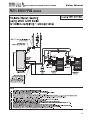
4. Condensate Neutralization
The condensate from the boiler is slightly
acidic with a ph of 3.2 - 4.5 Heat Transfer
Products recommends neutralizing the
condensate with a Condensate Neutralizer Kit
(p/n 7350P-611) that can be added to your
system to avoid long term damage to the
drainage system and to meet local code
requirements. The neutralizer kit is connected
to the drain system and contains marble
chips that will neutralize the ph level of the
water vapor. The neutralizer should be
checked at least once a year and the marble
chips should be replenished if necessary.
When replacing the marble chips, they
should be no smaller than ½” to avoid
blockage in condensate piping. (Refer to Fig.
6-1 and 6-2 for piping of the Condensate
neutralizer.)
Boiler Manual
GAS-FIRED HOT WATER SUPPLY BOILER
PART 6: VENTING, COMBUSTION AIR & CONDENSATE REMOVAL (CONTINUED)
&21'(16$7(1(875$/,=(5
:,7+2873803
6:($739&7((
23(172$70263+(5(
3,3(+$1*(5
$66(0%/,(6
)256833257
CONDENSATE
OVERFLOW SWITCH
NOTE: TO CLEAN OUT CONDENSATE
COLLECTOR ;USE A WET VAC INSIDE
THE OPEN PORT TO THE CONDENSATE
COLLECTOR. THIS WILL HELP REMOVE
ANY FOREIGN MATTER THAT MAY BLOCK
THE CONDENSATE LINE.
&21'(16$7(
1(875$/,=(5
39&6:($7
3,3,1*),77,1*6
CONDENSATE CAP
n WARNING
When servicing is complete, you must
make sure the cap is replaced securely.
Failure to do so will cause venting issue
that will result in serious injury or death.
)/225'5$,1
+25,=217$//,1(6
0867%(,167$//(':,7+
$3,7&+2)3(5)227
LP-205-ZZ Rev. 2/19/09
3,3(6833257
Fig. 6-1
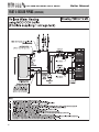
CONDENSATE NEUTRALIZER
WITH PUMP
&/($12873257
3/4" SWEAT PVC TEE
OPEN TO ATMOSPHERE
3/4" SWEAT PVC
PIPING/FITTINGS
PIPE HANGER
ASSEMBLIES FOR
SUPPORT
CONDENSATE PUMP
CONDENSATE
NEUTRALIZER
HORIZONTAL LINES MUST BE INSTALLED
WITH A PITCH OF 1/4" PER FOOT
PIPE SUPPORT
Fig. 6-2
LP-205-W Rev. 5/14/08
CLEAN OUT PORT
CAUTION
NOTICE
The condensate line must remain unobstructed,
allowing free flow of condensate. If condensate
is allowed to freeze in the line or if the line is
obstructed in any other manor, condensate can
exit from the boiler tee, resulting in potential
water damage to property.
When installing a condensate pump, select one
approved for use with condensing boilers and
furnaces. The pump should have an overflow
switch to prevent property damage from
condensate spillage.
Condensate from the Mod Con Boiler will be
slightly acidic (typically with a pH from 3.2 to
4.5). Install a neutralizing filter if required by
local codes.
32
GAS-FIRED HOT WATER SUPPLY BOILER
Boiler Manual
PART 6: VENTING, COMBUSTION AIR & CONDENSATE REMOVAL (CONTINUED)
Location of exit terminals of mechanical draft and direct-vent venting systems.
(Reference: National Fuel Gas Code ANSI Z223.1/NFPA 54 2002).
Fig. 6-3 Multiple Vents
Fig. 6-4 Multiple Vent Spacing*
*Note: Exhaust must extend out 1 foot. There should be no more than 2 vents and 2 intakes then a space of 36” to the
next set of vents.
*Note: There must be a minimum of 36” spacing between every 2 kit grouping.
Multiple “V” Series Vents
Fig. 6-6 Multiple Concentric Vent
Spacing – Vertical
Fig. 6-5 Multiple Stainless Steel Horizontal Vent Kit Installation – Front View
33
Boiler Manual
GAS-FIRED HOT WATER SUPPLY BOILER
PART 6: VENTING, COMBUSTION AIR & CONDENSATE REMOVAL (CONTINUED)
E. EXHAUST VENT AND INTAKE AIR VENT
SIZING
1. The exhaust vent and intake air vent pipes
are 4" for the Mod Con 300 and 500, and 6"
for the Mod Con 850.
2. The total combined equivalent length of
exhaust vent and intake air pipe should not
exceed 200 feet.
a. The equivalent length of elbows, tees,
and other fittings are listed in the Friction
Loss Table 6-8.
a. The maximum equivalent length for the
increased diameter vent pipes is 275 feet,
which includes the combined 32 feet from
the boiler, 16 ft. (inlet) + 16 ft. (exhaust) =
32 ft. combined with transition total of 245
ft. upsize piping for longer vent runs.
Table 6-9
Table 6-8
Friction Loss Equivalent for
Stainless or Plastic Piping and Fittings
Fitting Description
can be extended by increasing the diameter
of both exhaust vent and intake air vent pipe
equally. However, the transitions should
begin a minimum of 16 to 32 maximum
combined equivalent feet from the boiler on
both the intake and exhaust equally.
4"
6"
Reducing Coupling
Final Vent Size
8"
4" venting
6" x 4"
6"
6" venting
8" x 6"
8"
90° elbow short radius
3'
3'
3'
90° elbow long radius
2'
2'
2'
45° elbow
1'
1'
1'
Coupling
0'
0'
0'
Tee (intake only)
0'
0'
0'
V Series Vent Kit
1'
1'
1'
AL29 4C Vent Terminal 1'
1'
1'
Pipe (All materials)
1’
1’
1’
Vent Transition Fitting
Size
*Friction loss for long radius elbow is 1 foot less.
b. For example: If the exhaust vent has two
short 90° elbows and 10 feet of PVC pipe
we will calculate:
Exhaust Vent Pipe Equivalent Length = (2x3)+10=16 feet
Further, if the intake air vent pipe has two
short 90° elbows, one 45° elbow and 10
feet of PVC pipe, the following calculation
applies:
Intake Air Vent Pipe Equivalent Length = (2x3)+1+10=17 feet
c. The intake air vent pipe and the exhaust
vent are intended to penetrate the same
wall or roof of the building.
d. You should keep an equivalent length
between the intake air vent pipe and the
exhaust vent. The minimum combined
equivalent length is 16 to 32 maximum
combined equivalent feet.
F. LONGER VENT RUNS
1. The maximum combined equivalent length
NOTE: EXTENDED VENT
RUNS WHEN TRANSITIONING
TO A LARGER DIAMETER
MUST ALWAYS TAKE PLACE
IN A VERTICAL POSITION
TO PREVENT CONDENSATE
BLOCKAGE.
G. EXHAUST VENT AND INTAKE AIR PIPE
INSTALLATION
1. Use only solid PVC, or CPVC schedule 40 or
80 pipe and AL294C Stainless Steel. FOAM
CORE PIPING IS ONLY ALLOWED FOR
INTAKE PIPING.
2. Remove all burrs and debris from joints and
fittings.
3. All joints must be properly cleaned, primed,
and cemented. Use only cement and primer
approved for use with the pipe material.
Refer to the Venting Table 6-4.
n WARNING
All joints of positive pressure vent systems
must be sealed completely to prevent leakage
of flue products into the living space.
4. Horizontal lengths of exhaust vent must slope
back towards the boiler not less than ¼" per
foot to allow condensate to drain from the
34
GAS-FIRED HOT WATER SUPPLY BOILER
Boiler Manual
PART 6: VENTING, COMBUSTION AIR & CONDENSATE REMOVAL (CONTINUED)
vent pipe. If the exhaust pipe must be piped
around an obstacle that results in the creation
of a low point, condensate will collect in this
low point and form a blockage. This
condensate must be drained away using a
field-installed condensate drain assembly. All
vent pipes must be glued, properly
supported and the exhaust must be pitched
a minimum of ¼” per foot back to the boiler
to allow drainage of condensate. The
condensate drain piping should be a
minimum of ¾” PVC Rigid Piping, pitched at
a minimum of ¼” per foot away from the
boiler. (See Fig. 6-1, 6-2)
5. All piping must be fully supported. Use pipe
hangers at a minimum of 4 foot intervals to
prevent sagging of the pipe where
condensate may form. When placing support
brackets on vent piping, the first bracket must
be within 1 foot of the appliance and the
balance at 4 foot intervals on the vent pipe.
The boiler venting must be readily accessible
for visual inspection for the first three feet of
the boiler.
6. Do not use the boiler to support any piping.
7. A screened straight coupling is provided with
the boiler for use as an outside exhaust
termination.
8. A screened inlet air tee is provided with the
boiler to be used as an outside intake
termination.
H. HEATER REMOVAL FROM A COMMON
VENT SYSTEM
At the time of removal of an existing heater, the
following steps shall be followed with each
appliance remaining connected to the common
venting system placed in operation, while the
other appliances remaining connected to common venting system are not operating.
1. Seal any unused openings in the common
venting system.
2. Visually inspect the venting system for proper
size and horizontal pitch to determine if there
35
is blockage, leakage, corrosion or other deficiencies that could cause an unsafe condition.
3. If practical, close all building doors, windows
and all doors between the space in which the
appliance remains connected to the common
venting system located and other spaces in
the building. Turn on clothes dryers and any
appliances not connected to the common
venting system. Turn on any exhaust fans,
such as range hoods and bathroom exhausts,
at maximum speed. Do not operate a summer
exhaust fan. Close all fireplace dampers.
4. Place in operation the appliance being
inspected. Follow the lighting instructions.
Adjust the thermostat so the appliance will
operate continuously.
5. Test for spillage at the draft hood relief
opening after 5 minutes of main burner
operation. Use the flame of a match or candle
or smoke from a cigarette.
6. After it has been determined that each
appliance remaining connected to common
venting system properly vents when tested as
outlined, return doors, windows, exhaust fans,
fireplace dampers and any other gas burning
appliance to their previous condition of use.
7. Any improper operation of the common
venting system should be corrected so the
installation conforms with the National Fuel
Gas Code, ANSI Z223.1. When resizing any
portion of the common venting system, the
common venting system should be resized to
approach the minimum size as determined
using the appropriate tables in Appendix G in
the National Fuel Gas Code, ANSI Z 223.1
Note: For Canadian Installations, it is required
that Non Metallic Vent Installations conform to
ULC S636. Where plastic venting is not allowed,
HTP recommends AL294C Stainless Steel
Venting be used for Exhaust venting installations and “B” vent for intake air.
Please refer to 6-7 for U.L. Approved Stainless
Steel Vent Adapters.
Boiler Manual
GAS-FIRED HOT WATER SUPPLY BOILER
PART 6: VENTING, COMBUSTION AIR & CONDENSATE REMOVAL (CONTINUED)
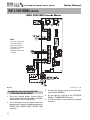
I. DIAGRAMS FOR SIDEWALL VENTING
TWO PIPE SIDEWALL VENTING W/TEE (INTAKE)
AND COUPLING (EXHAUST)
TWO PIPE SIDEWALL VENTING
WITH V-SERIES KIT
,1/(7(;+$867
6&5((1
VENT KIT
(SEE CHART)
$,5,17$.(
9(17
7((
0$;
7239,(:
SUPPORT BRACKETS
MUST BE USED ON
ALL HORIZONTAL
AND VERTICAL PIPING
675$,*+7
&283/,1*
(;+$867
9(17
EXHAUST
VENT
7' OR 1'
ABOVE MAX.
POTENTIAL SNOW LEVEL
,16(57,1/(7(;+$867
6&5((163529,'(',172
($&+(1'2)7((
,16(57,1/(7(;+$867
6&5((13529,'(',172
675$,*+7&283/,1*
0,1
0,1
6833257%5$&.(76
0867%(86('21
$//+25,=217$/
$1'9(57,&$/3,3,1*
675$,*+7
&283/,1*
(;+$867
9(17
RIGHT SIDE VIEW
INTAKE AIR
VENT
7((
25
$%29(0$;
327(17,$/612:/(9(/
5,*+76,'(9,(:
NOTE: VENT MUST BE AT LEAST 12" OVER MAXIMUM SNOW
LEVEL OR 24" WHICHEVER IS GREATER - CHECK WITH LOCAL
CODE REQUIREMENTS
NOTE: THE EXHAUST VENT
CONNECTION MUST BE INSERTED A
MINIMUM OF 2-1/2"
FOR THE MODCON 300/500
AND 3" FOR THE MODCON 850
$,5,17$.(
9(17
127(9(170867%($7/($6729(50$;,080612:
/(9(/25:+,&+(9(5,6*5($7(5&+(&.:,7+/2&$/
&2'(5(48,5(0(176
Figure 6-7
LP-205-E Rev. 6/23/08
1. Prep PVC Pipe by removing burrs on the leading edge before inserting
into the boiler adapter to prevent damage to internal o-ring seal.
Do not use any Liquids or Petroleum based products that could
damage the o-ring seal - It is recommended you use talcum powder
to assist in inserting pipe into adapter.
2. Tighten clamp to a maximum of 50 inch pounds to avoid reforming
connected PVC which may cause combustion leaks.
Figure 6-8
LP-205-F Rev. 5/15/08
n WARNING
All vent pipes must be glued, properly supported and the exhaust must be pitched a minimum of a ¼" per
foot back to the heater (to allow drainage of condensate). Exhaust connection insertion depth should be a
minimum of 2½” for models 300/500 and 3” for 850. When placing support brackets on vent piping, the
first bracket must be within 1 foot of the appliance and the balance at 4 foot intervals on the vent pipe.
The boiler venting must be readily accessible for visual inspection for the first three feet from the boiler.
36
Boiler Manual
GAS-FIRED HOT WATER SUPPLY BOILER
PART 6: VENTING, COMBUSTION AIR & CONDENSATE REMOVAL (CONTINUED)
J. DIAGRAM FOR VERTICAL VENTING
TWO PIPE ROOF VENTING WITH TEE (INTAKE)
AND COUPLING (EXHAUST)
,16(57,1/(7(;+$867
6&5((13529,'(',172
675$,*+7&283/,1*
,16(57,1/(7(;+$867
6&5((163529,'(',172
($&+(1'2)7((
675$,*+7
&283/,1*
0,1
7((
0,1
29(50$;,080
612:/(9(/25
:+,&+(9(5,6*5($7(5
(;+$867
9(17
5,*+76,'(9,(:
Fig. 6-10 Multiple Concentric Vent
Spacing – Vertical
(;7(5,25:$//
,17$.($,5
9(17
Fig. 6-11 Multiple Concentric Vent
Spacing – Horizontal
127(9(170867%($7/($6729(50$;,080612:
/(9(/25:+,&+(9(5,6*5($7(5&+(&.:,7+/2&$/
&2'(5(48,5(0(176
Figure 6-9
LP-205-G Rev. 6/23/08
n WARNING
All vent pipes must be glued, properly supported and the exhaust must be pitched a minimum of a ¼" per
foot back to the heater (to allow drainage of condensate). Exhaust connection insertion depth should be a
minimum of 2½” for models 300/500 and 3” for 850. When placing support brackets on vent piping, the
first bracket must be within 1 foot of the appliance and the balance at 4 foot intervals on the vent pipe.
The boiler venting must be readily accessible for visual inspection for the first three feet from the boiler.
37
Boiler Manual
GAS-FIRED HOT WATER SUPPLY BOILER
PART 6: VENTING, COMBUSTION AIR & CONDENSATE REMOVAL (CONTINUED)
10’ 0" MIN.
24" MIN.
ROOF EXHAUST
RAIN CAP - STAINLESS STEEL
4" Z-FLEX 2SVSRCF04
6" Z-FLEX 2SVSRC06
DIAGRAM FOR HORIZONTAL VENTING
RIZONTAL VENTING
AIR INTAKE
GALVANIZED/B-VENT
12" OVER MAXIMUM
SNOW LEVEL OR 24"
WHICHEVER IS GREATER
E
ROOF VENTING WITH
STAINLESS STEEL (AL294C)
A
A. FOR EVERY 1" OF
OVERHANG THE
EXHAUST VENT
D
MUST BE
LOCATED 1"
MULTIPLE BOILERS
VERTICAL BELOW
C
OVERHANG
(OVERHANG
MEANS TOP OF
SINGLE BOILER
BUILDING
STRUCTURE AND NOT TWO ADJACENT WALLS [CORNER OF
BUILDING]).
B. 12" SEPARATION BETWEEN BOTTOM OF EXHAUST OUTLET AND TOP
OF AIR INTAKE (TYP.)
C. MAINTAIN 12" MINIMUM CLEARANCE ABOVE HIGHEST ANTICIPATED
SNOW LEVEL OR GRADE WHICHEVER IS GREATER (TYP.)
D. MINIMUM 12" BETWEEN VENTS WHEN INSTALLING MULTIPLE VENTS
E. 12 " MIN. BEYOND INTAKE
SUPPORT
BRACKETS
Figure 6-12
VT-A Rev. 8/28/09
SIDEWALL VENTING
WITH STAINLESS STEEL
AIR INTAKE
GALVANIZED
B-VENT
SIDE WALL EXHAUST
TERMINATION
4" Z-FLEX 2SVSRTF04
6" Z-FLEX 2SVSRTX06
12"
SUPPORT
BRACKETS
12"
7’ or 1’
ABOVE MAX.
POTENTIAL
SNOW LEVEL
NOTE: VENT MUST BE AT LEAST 12" OVER MAXIMUM SNOW
LEVEL OR 24" WHICHEVER IS GREATER - CHECK WITH LOCAL
CODE REQUIREMENTS
Figure 6-13
LP-205-Y Rev. 1/30/09
n WARNING
All vent pipes must be glued, properly supported and the exhaust must be pitched a minimum of a ¼" per
foot back to the heater (to allow drainage of condensate). Exhaust connection insertion depth should be a
minimum of 2½” for models 300/500 and 3” for 850. When placing support brackets on vent piping, the
first bracket must be within 1 foot of the appliance and the balance at 4 foot intervals on the vent pipe.
The boiler venting must be readily accessible for visual inspection for the first three feet from the boiler.
38
Boiler Manual
GAS-FIRED HOT WATER SUPPLY BOILER
PART 7: GAS PIPING
n WARNING
Failure to follow all precautions in this section
could result in fire, explosion or death!
A. GAS CONNECTION
The gas supply shall have a maximum inlet
pressure of less than 14" w.c. (3.5 kPa), and a
minimum of 3.5" w.c. (.87 kPa). The entire piping
system, gas meter and regulator must be sized
properly to prevent pressure drop greater than
0.5" (.12 kPa) as stated in the National Fuel Gas
Code. This information is listed on the rating
label.
If the leak test requirement is a higher test pressure than the maximum inlet pressure, you must
isolate the Mod Con from the gas line. In order
to do this, you must shut the gas off using factory and field-installed gas cocks. This will prevent high pressure. Failure to do so may damage the gas valve. In the event the gas valve is
exposed to a pressure greater than ½ PSI, 14"
w.c. (3.5 kPa), the gas valve must be replaced.
Never use an open flame (match, lighter, etc.) to
check gas connections.
B. GAS PIPING
1. Run the gas supply line in accordance with all
applicable codes.
2. Locate and install manual shutoff valves in accordance with state and local requirements.
3. In Canada, the Manual Shutoff must be
identified by the installing contractor.
4. It is important to support gas piping as the
unit is not designed to structurally support
large amount of weight.
5. Purge all gas lines thoroughly to avoid start
up issues with air in the lines.
n WARNING
It is very important that you are connected to
the type of gas as noted on the rating plate.
“LP” for liquefied petroleum, propane gas or,
“Nat” natural or city gas. You must not do a gas
conversion on this boiler. All gas connections
must be approved by the local gas supplier, or
utility in addition to the governing authority,
prior to turning the gas supply on.
The gas connection on the Mod Con is 1-1/4” for
the Mod Con 300, 1-1/2” for the Mod Con 500
and 2” for the Mod Con 850. It is mandatory that
this fitting is used for connection to a field fabricated drip leg as shown in the illustration above
per the National Fuel Gas Code. You must
ensure that the entire gas line to the connection
at the Mod Con is no smaller than the unit supplied connection. Once all the inspections have
been performed, the piping must be leak tested.
39
6. Sealing compound must be approved for gas
connection. Care must be taken when
applying compound to prevent blockage or
obstruction of gas flow which my effect the
operation of the unit.
n WARNING
Never use an open flame (Match or Lighter) to
check for Gas leaks. Use A soapy solution to
test gas connection for leaks. Failure to use
soapy solution test or check gas connection for
leaks can cause substantial property damage,
severe personal injury or death .
NOTICE
CSA or UL listed Flexible gas connections can
be used when installing The Mod Con Boiler.
Flexible gas connections have different
capacities and must be sized correctly for the
connected boiler firing rates. Consult with the
flex line supplier to assure the line size is
adequately sized for the job. Follow local codes
for proper installation and service requirements.
Boiler Manual
GAS-FIRED HOT WATER SUPPLY BOILER
PART 7: GAS PIPING (CONTINUED)
C. GAS TABLE
Refer to Table 7-1 to size the supply piping to
minimize pressure drop between meter or
regulator and unit.
Maximum Capacity of Pipe in Cubic Feet of Gas
per Hour for Gas Pressures of 0.5 w.c. or Less and
a Pressure Drop of 0.3 Inch w.c.
Table 7-1
NATURAL GAS SUPPLY PIPING CAPACITY CHART
(0.6 specific gravity gas; 0.5” WC pressure drop)
*Schedule 40 iron pipe size in nominal inch size
Boiler Model
1 Boiler
Cubic Ft. Hr.
300
2 Boilers 3 Boilers 4 Boilers 5 Boilers 6 Boilers 7 Boilers 8 Boilers
600
900
1200
1500
1800
2100
2400
ModCon 300 VWH @ 100’ of pipe
1 1/4”
1 1/2”
2”
2 1/2”
2 1/2”
2 1/2”
3”
3”
2”
2 1/2”
3”
3”
3”
4”
4”
ModCon 300 VWH @ 250’ of pipe
1 1/2”
Boiler Model
1 Boiler
Cubic Ft. Hr.
500
ModCon 500 VWH @ 100’ of pipe
ModCon 500 VWH @ 250’ of pipe
Boiler Model
1 Boiler
Cubic Ft. Hr.
850
1700
2550
3400
4250
5100
5950
6800
ModCon 850 VWH @ 100’ of pipe
2”
2 1/2”
3”
4”
4”
4”
4”
5”
ModCon 850 VWH @ 250’ of pipe
2 1/2”
3”
4”
4”
5”
5”
5”
5”
2 Boilers 3 Boilers 4 Boilers 5 Boilers 6 Boilers 7 Boilers 8 Boilers
1000
1500
2000
2500
3000
3500
4000
1 1/2”
2”
2 1/2”
3”
3”
3”
4”
4”
2”
2 1/2”
3”
3”
4”
4”
4”
4”
2 Boilers 3 Boilers 4 Boilers 5 Boilers 6 Boilers 7 Boilers 8 Boilers
D. CHECK INLET GAS PRESSURE
The Gas Valve is equipped with an Inlet Gas
Pressure Tap that can be used to measure the
gas pressure to the unit. To check Gas Pressure
perform the steps listed below:
1. Before you connect to the inlet pressure you
must shut off the gas and electrical power to
unit.
2 Loosen the pressure tap with a small
screwdriver. Refer to Figures 7-2, 7-3 and 7-4
for location.
3. Each unit is equipped with a needle valve
that will accept a 5/16 ID hose to connect to
a digital manometer or liquid gauge to
measure incoming pressure from 0-35” w.c.
4. Turn on the Gas and Power up the unit.
5. Put the unit into manual service mode
(Details on service mode in back of this
manual). In service mode, monitor pressure
to assure it does not drop below 1 inch from
its idle reading. If Gas Pressure is out of range
or pressure drop is excessive, contact the gas
utility, gas supplier, qualified installer or
service agency to determine correct action
that is needed to provide proper gas pressure
to the unit. If Gas Pressure is within normal
range proceed to Step 6.
6. Exit Service mode, then turn power off and
shut off gas supply at the manual gas valve
before disconnecting the hose from the gas
monitoring device. Tighten the screw on the
pressure tap tightly and turn gas on and
checks for leaks with soapy solution.
It is recommended that a soapy solution be used
to detect leaks. Bubbles will appear on the pipe
to indicate a leak is present. The gas piping must
be sized for the proper flow and length of pipe,
to avoid pressure drop. Both the gas meter and
the gas regulator must be properly sized for the
total gas load. If you experience a pressure drop
greater than 1" w.c. (.87 kPa), the meter, regulator or gas line is undersized or in need of service. You can attach a manometer to the incoming gas drip leg, by removing the cap and
installing the manometer. The gas pressure
must remain between 3.5" (.87 kPa) and 14" (3.5
kPa) during stand-by (static) mode and while in
operating (dynamic) mode. If an in-line regula40
GAS-FIRED HOT WATER SUPPLY BOILER
Boiler Manual
PART 7: GAS PIPING (CONTINUED)
tor is used, it must be a minimum of 10 feet from
the Mod Con. It is very important that the gas
line is properly purged by the gas supplier or
utility. Failure to properly purge the lines or
improper line sizing, will result in ignition failure. This problem is especially noticeable in
NEW LP installations and also in empty tank situations. This can also occur when a utility company shuts off service to an area to provide
maintenance to their lines. This gas valve must
not be replaced with a conventional gas valve
under any circumstances.
E. DUNGS GAS VALVE
MOD CON 300 GAS VALVE
THROTTLE ADJUSTER
GAS OUTLET
GAS OUTLET
PRESSURE TAP
DETAIL A
SCALE 2 : 3
NOTE: IF FOR ANY REASON THE THROTTLE
NEEDS TO BE ADJUSTED, IT IS VERY IMPORTANT
THAT A "COMBUSTION ANALYZER" BE USED TO
ENSURE SAFE AND PROPER OPERATION.
TURN THE ADJUSTER TO THE (+) TO INCREASE
THE GAS OR (-) TO DECREASE THE GAS SUPPLY.
THIS ADJUSTMENT COULD AFFECT CO/CO%
LEVELS. MAKE SURE THE LEVELS CORRESPOND
TO THE CHART IN COMBUSTION SETTINGS.
(FIG. 10-1)
A
OFFSET ADJUSMENT
GAS VALVE
GAS INLET
PRESSURE TAP
CAUTION: DO NOT REMOVE THIS SCREW
OR ATTEMPT TO MAKE ANY ADJUSTMENT TO
THIS SCREW WITHOUT A COMBUSTION
ANALYZER
GAS INLET
GAS SHUT-OFF
VALVE
Fig. 7-2
41
LP-205-AA Rev. 6/3/08
GAS-FIRED HOT WATER SUPPLY BOILER
Boiler Manual
PART 7: GAS PIPING (CONTINUED)
MOD CON 500 GAS VALVE
THROTTLE ADJUSTER
NOTE: IF FOR ANY REASON THE THROTTLE
NEEDS TO BE ADJUSTED, IT IS VERY IMPORTANT
THAT A "COMBUSTION ANALYZER" BE USED TO
ENSURE SAFE AND PROPER OPERATION. TURN
THE ADJUSTER TO THE (+) TO INCREASE THE GAS
OR (-) TO DECREASE THE GAS SUPPLY. THIS
ADJUSTMENT COULD AFFECT CO/CO% LEVELS.
MAKE SURE THE LEVELS CORRESPOND TO THE
CHART IN COMBUSTION SETTINGS.
(FIG. 10-1)
GAS PRESSURE
SWITCH BLOCK
GAS OUTLET
PRESSURE TAP
DETAIL A
SCALE 2 : 3
GAS OUTLET
GAS VALVE
GAS INLET
PRESSURE TAP
A
OFFSET ADJUSTMENT
CAUTION: DO NOT REMOVE THIS SCREW
OR ATTEMPT TO MAKE ANY ADJUSTMENT TO
THIS SCREW WITHOUT A COMBUSTION ANALYZER
GAS PRESSURE
SWITCH BLOCK
GAS INLET
GAS SHUT-OFF
VALVE
Fig. 7-3
LP-205-BB Rev. 6/3/08
42
Boiler Manual
GAS-FIRED HOT WATER SUPPLY BOILER
PART 7: GAS PIPING (CONTINUED)
MOD CON 850 GAS VALVE
THROTTLE ADJUSTER
NOTE: IF FOR ANY REASON THE THROTTLE NEEDS TO BE
ADJUSTED, IT IS VERY IMPORTANT THAT A COMBUSTION
ANALYZER BE USED TO ENSURE SAFE AND PROPER
OPERATION. TURN THE ADJUSTER TO THE (+) TO INCREASE
GAS SUPPLY OR TO THE (-) TO DECREASE GAS SUPPLY.
THIS ADJUSTMENT COULD AFFECT CO/CO% LEVELS.
MAKE SURE THE LEVELS CORRESPOND TO THE CHART IN THE
COMBUSTION SETTINGS SECTION (FIG. 10-1)
DETAIL A
SCALE 2:1.5
GAS VALVE
GAS PRESSURE
SWITCH BLOCK
INTERMEDIATE
PRESSURE TAP
GAS SHUT OFF
VALVE
GAS PRESSURE
SWITCH BLOCK
A
GAS INLET
GAS OUTLET
B
GAS OUTLET
PRESSURE
TAP
GAS INLET
PRESSURE
TAP
OFFSET ADJUSTMENT
DETAIL B
SCALE 2:1.5
Fig. 7-4
43
CAUTION: DO NOT REMOVE THIS SCREW OR ATTEMPT TO
MAKE ANY ADJUSTMENT TO THIS SCREW WITHOUT USING
A COMBUSTION ANALYZER.
LP-205-O Rev. 5/27/08
GAS-FIRED HOT WATER SUPPLY BOILER
Boiler Manual
PART 8: FIELD WIRING
n WARNING
ELECTRICAL SHOCK HAZARD — For your
safety, turn off electrical power supply at service
entrance panel before making any electrical
connections to avoid possible electric shock
hazard. Failure to do so can cause severe
personal injury or death.
NOTICE
Wiring must be N.E.C. Class 1.
If original wiring as supplied with boiler must be
replaced, use only TEW 105 °C wire or
equivalent.
Boiler must be electrically grounded as required
by National Electrical Code ANSI/NFPA 70 —
latest edition.
A. INSTALLATION MUST COMPLY WITH:
1. National Electrical Code and any other
national, state, provincial or local codes or
regulations.
2. In Canada, CSA C22.1 Canadian Electrical
Code Part 1, and any local codes.
B. FIELD WIRING TERMINATIONS
All connections to the MODCON VWH boiler in
the field are made inside the electrical junction
box located on the side of the unit. The electrical junction box is located on the left side of the
MOD CON 500 and 850 and on the right side of
the MOD CON 300 units. Multiple knockout locations are available to route field wires into and
out of the electrical junction box.
C. FIELD WIRING CONSIDERATIONS
NOTICE
CHECK WATER CHEMISTRY SECTION FOR
ACCEPTABLE LEVELS. IF ACCEPTABLE, PUMPS
M AY B E W I R E D D I R E C T LY T O P U M P
TERMINALS. IF LEVELS ARE TOO HIGH, YOU
MUST WIRE PUMPS TO LINE VOLTAGE TO RUN
CONTINUOUSLY TO PREVENT LIME BUILD UP.
Pumps
The Mod/Con VWH Application requires a circulator pump for each boiler. Circulator pumps can
be wired directly to the controller as shown figures 8-1/8-3/8-4 or wired directly to line voltage
for continuous operation. Only wire the circulator pump to the controller if a Tank Sensor or
Mechanical control can be mounted to the storage tank, otherwise circulator pumps must be
wired to run continuously. The circulator pump
wired to the boiler control will have a default
program of a 5 minute post purge to provide
stabilization and post cleaning of the heat
exchanger. The boiler control is capable of supplying 120 volts at up to 3 amps to run the circulator pump. If using a larger circulator pump
requiring more than 3 amps or higher voltage,
an external motor starter, sized appropriately for
the pump motor must be used. This starter
should have a 120 VAC coil. If a starter with 120
VAC coil is used, it can be wired directly to the
appropriate pump terminals as shown on figures 8-1 / 8-3/8-4 Mod/Con VWH.
Tank and Sensor Connections
When the MOD CON VWH is used in a single
boiler installation, it is recommended to use a
sensor (7250P-325) placed in a well in the storage tank for the best temperature control. If multiple tanks are used in the installation, it is recommended to put a mechanical aquastat in each
tank and wire them in series to provide temperature control of the tanks. See piping/sensor diagrams in Part 5 section G for reference. The control in the MODCON VWH will read either the
temperature of the tank sensor or the status of
the aquastats and cause the boiler to run until
the water temperature of the tank is at the
desired set point. If a sensor or aquastat cannot
be placed directly in the tank, then one sensor
should be used on the pipe carrying the water
from the tank(s) to the boiler. This sensor should
be placed as close to the tank(s) as possible in
the common piping to minimize loss of temperature in the piping. The use of a pipe sensor will
be somewhat less accurate than using a sensor
in the tank and has the disadvantage of requiring the boiler pump(s) to run continuously so
the sensor is always measuring the temperature
of the water that is in the tank.
In a multiple MODCON VWH installation, where
the boilers are connected for cascade operation,
a system sensor is needed in addition to the
tank or pipe sensor described above. The system sensor is mounted on the common pipe to
44
GAS-FIRED HOT WATER SUPPLY BOILER
Boiler Manual
PART 8: FIELD WIRING (CONTINUED)
the tank(s) from the boilers as close to the
tank(s) as possible. The purpose of this sensor is
to serve as feedback to the control to provide it
with the aggregate temperature of all boilers firing. The master boiler control will then fire the
boilers in cascade sequence to maintain the
water in this pipe at the appropriate temperature
to provide correct heating of the tank.
The electrical junction box has separate, clearly
marked terminal strips for line voltage and low
voltage wiring. Special jacks are provided for
trouble-free cascade system wiring using standard CAT3 or CAT5 patch cables.
D. LINE VOLTAGE WIRING FOR
MODCON VWH
Connect the incoming power wiring to the line
voltage terminal strip in the electrical junction
box at terminals LINE 120V, Neutral, Ground
(Shown in Fig. 8-1). A line voltage fused disconnect switch may be required to be externally
mounted and connected according to local
wiring codes that may apply.
If the pump used for the boiler operates at 120
volt and less than 3 amps is required, it may be
connected directly to the terminals marked
BOILER HOT, BOILER NEUT, BOILER GRD. If the
pump operates at a voltage other than 120 volts
and/or it requires more than 3 amps, an external
motor starter must be used to operate the
pump. If the starter is equipped with a 120 volt
coil, the coil connections may be connected
directly to the terminals marked BOILER HOT
and BOILER NEUT. Refer to Fig 8-1a for a representative drawing of this configuration. If a
motor starter is used, it should be selected,
installed and wired in compliance with all local
electrical codes and requirements. In the
absence of such codes or requirements, the
National Electrical Code (NFPA 70) should be followed.
E. ALARM CONNECTIONS
The MOD CON control includes a dry contact
alarm output. This is an SPDT circuit, rated at 5
amps at 120 volts. This contact can be used to
activate an alarm light or bell or notify a building
management system if the boiler goes into a
lockout condition. The circuit between the
ALARM COM and NC terminals is closed during
45
normal operation and the circuit between
ALARM COM and NO is open during normal
operation. The connections depicted in figure 81 show two 120 volt lights connected to the
alarm terminals. One light will be on when the
boiler is in normal mode and the other light will
be on when the boiler is in lockout mode.
F. LOW VOLTAGE CONNECTIONS FOR
STANDARD BOILER
1. All low voltage cables should enter the
electrical junction box through the provided
knock out holes as shown below.
2. Connect all low voltage field devices to the
low voltage terminal strip located in the
electrical junction box (shown in Figure 8-1).
GAS-FIRED HOT WATER SUPPLY BOILER
Boiler Manual
PART 8: FIELD WIRING (CONTINUED)
MOD CON VWH CONTROL
Fig. 8-1
LP-248-VWH Rev. 7/17/09
46
GAS-FIRED HOT WATER SUPPLY BOILER
Boiler Manual
PART 8: FIELD WIRING (CONTINUED)
G TANK SENSOR OR MECHANICAL
CONTROL
Connect the tank sensor or mechanical controls
to the TANK SENSOR terminals of the low voltage terminal strip as shown in Fig. 8-1. The control will automatically determine which type of
sensor is connected and will operate accordingly. Caution should be used to ensure that neither
of these terminals becomes connected to
ground.
H. SYSTEM / PIPE SENSOR
The System/Pipe sensor can be used to control
the temperature of the storage tank when a Tank
Sensor or Mechanical control cannot be mounted. The System/Pipe Sensor would be wired
into the terminals of the low voltage terminal
strip as shown on figure 8-1. It is important to
note that when a System/Pipe Sensor is used,
the circulating pump must be wired to operate
continuously, otherwise the boiler will short
cycle.
The System/Pipe sensor can also be used in a
Cascade System when the sensor is placed on
the supply line of multiple boilers that feed the
storage tank. This will control the temperature
and modulate the firing rate of the connected
boilers. The System/Pipe Sensor would then be
wired into the Master Boiler terminals on the low
voltage strip as shown on figure 8-3.
I. OPTIONAL HIGH GAS PRESSURE
SWITCH
1. If an optional high gas pressure switch is
47
used, it should be installed on the outlet side
of the gas valve. This is normally closed and
will open if the pressure goes above 1.5” w.c.
on the outlet side.
2. Locate the two pigtails hanging from the
electrical box inside of the boiler cabinet.
Remove and discard the jumper plug from
one of the unused pigtails.
3. Connect the high gas pressure switch to the
pigtail that you removed the jumper plug
from.
J. OPTIONAL LOW GAS PRESSURE
SWITCH
1. If an optional low gas pressure switch is
used, it should be installed on the inlet side
of the gas valve. This is normally closed and
will open if the pressure goes below 1” w.c.
on the inlet side.
2. Locate the two pigtails hanging from the
electrical box inside of the boiler cabinet.
Remove and discard the jumper plug from
one of the unused pigtails.
3. Connect the low gas pressure switch to the
pigtail that you removed the jumper plug from.
K. FLOW SWITCH
The MODCON VWH boiler requires the use of a
flow switch. The flow switch kit 7350P-605 or
7350P-606 is part of the VWH conversion
process and comes packaged with detailed
installation instructions which should be read
and followed to ensure a functional system
GAS-FIRED HOT WATER SUPPLY BOILER
Boiler Manual
PART 8: FIELD WIRING (CONTINUED)
L. WIRING OF CASCADE SYSTEM
COMMUNICATION BUS
1. Use standard CAT3 or CAT5 computer
network patch cables to connect the
communication bus between each of the
boilers. Use standard ‘straight through’
cables for these connections. Do not use
crossover cables. These cables are readily
available at any office supply, computer,
electronic, department or discount home
supply store in varying lengths. If you
possess the skills you can also construct
custom length cables.
2. It is recommended to use the shortest length
cable that will reach between the boilers and
create a neat installation. Do not run
unprotected cables across the floor or where
they will become wet or damaged. Avoid
running communication cables parallel and
close to or against high voltage (120 volt or
greater) wiring. HTP recommends that the
maximum length of communication bus
cables not exceed 200 feet.
3. Route the communication cables through
one of the knockouts in the cabinet.
4. Connect the boilers in a daisy chain
configuration as shown below. It is best to
wire the boilers using the shortest wire runs
rather than trying to wire them in the order
that they are addressed. The communication
bus jacks on the customer connection panel
are interchangeable so you can use either
one or both in any order to connect the cable
to. If you have connected the boilers to each
other properly, two of the boilers will have
one open connection port on them.
UNUSED COMMUNICATION
B JACK AVAILABLE TO
CONNECT TO VISION 2.
UNUSED COMMUNICATION
BUS JACK AVAILABLE TO
CONNECT TO VISION 2.
Fig. 8-2
LP-205-JJ
48
GAS-FIRED HOT WATER SUPPLY BOILER
Boiler Manual
PART 8: FIELD WIRING (CONTINUED)
MOD CON VWH Cascade Master
NOTE:
You must place the
Cascade Master
label (included in
shipping envelope)
on top of the
Standard Mod Con
Control
Fig. 8-3
M. MODCON VWH CASCADE MASTER
PUMP AND SENSOR WIRING
1. Place the Cascade Master Overlay Sticker
onto the field connection board on the boiler
designated as the Cascade Master
2. If it is desired to have the boiler control the
boiler pump, Connect the boiler pump to the
BOILER HOT, BOILER NEUT, BOILER GND
terminals
49
LP-248-VWH Rev. 7/17/09
3. Connect the System sensor to the terminals
marked SYS SENSOR
4. Do not connect anything to the OUTDOOR
SENS or THERMOSTAT terminals
5. If 0–10 volt input is used, connect to marked
terminals.
GAS-FIRED HOT WATER SUPPLY BOILER
Boiler Manual
PART 8: FIELD WIRING (CONTINUED)
MOD CON VWH Cascade Follower
Fig. 8-4
N. MODCON VWH CASCADE FOLLOWER
PUMP AND SENSOR WIRING
1. If it is desired to have the boiler control the
boiler pump, Connect the boiler pump to the
BOILER HOT, BOILER NEUT, BOILER GND
terminals
2. Connect the tank sensor(s) or return sensor
to the terminals marked TANK SENSOR on
the follower boiler addressed as 1. There are
no connections to these terminals on other
LP-248-VWH Rev. 7/10/09
follower boilers in the system.
3. Do not connect anything to the OUTDOOR
SENS, 0-10V or THERMOSTAT terminals.
4. If it is desired to monitor the boiler system to
detect a lockout condition, a dry contact
alarm relay is provided. Please see Figure 8.4
for wiring suggestions for this relay. Note that
the alarm output of the boiler addressed as 1
will be active for lockout alarms both on
boiler 1, as well as on the master boiler.
50
GAS-FIRED HOT WATER SUPPLY BOILER
Boiler Manual
PART 8: FIELD WIRING (CONTINUED)
Fig. 8-5
51
LP-255 Rev. 11/09/09
GAS-FIRED HOT WATER SUPPLY BOILER
Boiler Manual
PART 9. START-UP OPERATION
A. SINGLE MOD CON VWH BOILER
When power is applied to the MODCON VWH
boiler, the control first completes a power-up
systems check. During this time, the combustion fan may run. The display will initially show
the current boiler outlet temperature. If a fault is
detected during the power-up test time, the control will display the appropriate fault code. If all
is well, the display will continue to show the
boiler outlet temperature and stand by waiting
for a demand for hot water. If the temperature of
the tank sensor falls to below the tank set point/
|dd| - tank differential |dh| temperature, a demand
for hot water is generated by the control. When
a demand for hot water is received, the control
begins the following the demand sequence. The
control will energize the pump output then wait
for adequate water flow to pass through the flow
switch. If the flow is not sufficient, the display
will show |FL| until the flow is sufficient. Once the
flow through the boiler is adequate, the control
will then measure the boiler supply temperature
and if it is below the set point temperature |dd| –
the supply hysteresis |Sh| temperature, the control will ignite the burner. Once the boiler is lit,
the control will modulate the firing rate to control the supply water temperature to be at the
supply offset temperature (installer #4) above
the tank set point temperature |dd|. When the
tank temperature is equal to the tank set point
temperature, the control will extinguish the
burner and allow the combustion fan to run for
a time to purge gas from the combustion chamber. The control will then be in stand-by waiting
to process the next demand for heat. In the
event that the control goes into lockout, it will
close the alarm contacts, show a diagnostic
code on the display, and illuminate the LED fault
indicator to assist in trouble shooting the failed
condition. If you have an alarm connected to the
alarm contacts it will be activated.
B. MULTIPLE MOD CON VWH BOILERS
If the MODCON VWH boiler is part of a cascaded boiler system, then the operation is somewhat different. The control of each boiler in the
cascaded system completes its own power up
systems check as described above. One of the
boilers in the cascade system is designated as
the master boiler. After the master boiler completes its power up sequence, it checks the com-
munication bus to see if any other boilers are
present and if there are boilers present, the master control determines their boiler address. The
master boiler control will re-check the bus every
few seconds as long as it is powered up to
update the status of the connected boilers. The
control in the master boiler is the one that
processes all heat demands and dictates which
of the follower boilers should light and at what
firing rate the followers should run at. When the
master boiler receives a demand for heat, it
determines which boiler is the first in the firing
sequence and sends that boiler a command to
begin a demand sequence. That boiler will then
begin a demand sequence exactly as described
above. Once that boiler ignites, the master boiler control will increase the firing rate of that boiler until the system sensor temperature is at the
supply offset temperature (master boiler
installer #4) above the tank set point temperature or that boiler is at high firing rate. If the boiler gets to a high firing rate but the system sensor is not at the desired temperature, the master
boiler control will then tell the next boiler in the
firing sequence to begin its demand sequence.
The second boiler will then begin to ramp up in
firing rate based on commands from the master
boiler control. This process will continue while
there is a demand, until either all boilers in the
cascade system are at high fire or the desired
temperature at the system sensor is reached.
When the tank temperature is equal to the set
point temperature the demand is complete and
the master boiler control will extinguish all boilers that may be lit. If any boiler or multiple boilers, including the master boiler in the cascade
system are in a lockout condition, the master
control will recognize the lockout condition and
skip over the boiler in the firing sequence. Each
boiler in the cascade system is responsible for
its own safety functions so if any individual boiler control senses an unsafe condition it will
extinguish the boiler and if necessary, put it in
lockout condition. In this way, every boiler in the
system has its individual safety controls intact
and operational even if the firing of the boiler is
under control of the master boiler. In the event
that the system sensor fails, all boilers in the
system will ignite simultaneously when there is
a demand and they will regulate their firing rate
individually to maintain the master set point
temperature (tank set point + master boiler
installer #4) at their individual supply sensors
52
GAS-FIRED HOT WATER SUPPLY BOILER
Boiler Manual
PART 9. START-UP PREPARATION (CONTINUED)
built into the boiler. If this should happen, the
master boiler will display an E03 fault code indicating that the supply sensor has failed.
C. CHECK FOR GAS LEAKS
n WARNING
outlet on the Mod Con is lower than the drain,
you must use a condensate removal pump,
available from Heat Transfer Products
(#554200). This pump is equipped with two
leads that can be connected to an alarm or
another type of warning device to alert the
user of a condensate overflow, which, if not
corrected, could cause property damage.
Before starting the boiler, and during initial
operation, smell near the floor and around the
boiler for gas odorant or any unusual odor.
Remove boiler front door and smell interior of
boiler enclosure. Do not proceed with startup if
there is any indication of a gas leak. Repair any
leak at once.
3. If a long horizontal run is used, it may be
necessary to create a vent in the horizontal to
prevent a vacuum lock in the condensate
line.
n WARNING
5. It is very important you support the
condensation line to assure proper drainage.
Propane boilers only — Your propane supplier
mixes an odorant with the propane to make its
presence detectable. In some instances, the
odorant can fade, and the gas may no longer
have an odor. Before startup (and periodically
thereafter), have the propane supplier verify the
correct odorant level in the gas.
E. FINAL CHECKS BEFORE STARTING BOILER
D. CONDENSATE REMOVAL
1. The Mod Con Boiler is a high efficiency
condensing boiler, therefore, the unit has a
condensate drain. Condensate fluid is
nothing more than water vapor, derived from
combustion products, similar to an
automobile when it is initially started. The
condensation is slightly acidic (typically with
pH of 3 to 5) and must be piped with the
correct materials. Never pipe the condensate
using steel, copper, brass or other materials
that will be subject to corrosion. Plastic PVC
or CPVC pipe are the only approved
materials. A condensate filter, if required by
local authorities, can be made up of lime
crystals, marble or phosphate chips that will
neutralize the condensate. This may be done
by the installer or you may purchase a
condensate neutralizer from Heat Transfer
Products, Inc. (P/N S7350-025)
2. The Mod Con Boiler is equipped with a ¾ FPT
connection that must be piped to a local drain.
It is very important that the condensate line is
sloped downward away from the Mod Con to
a suitable inside drain. If the condensate
53
4. Do not expose the condensate to freezing
temperatures.
1. Read Startup Procedures within this manual
for proper steps to start boiler. (See Startup
Report to record steps for future reference.)
2. Verify the boiler and system are full of water
and all system components are correctly set
for operation.
3. Fill condensate trap with water.
4. Verify electrical connections are correct and
securely attached.
5. Inspect intake piping and exhaust piping for
signs of deterioration from corrosion, physical
damage or sagging. Verify intake piping and
exhaust piping are intact and correctly
installed per Venting section and local code.
F. CASCADE SYSTEM
1. If the boiler is used in a stand alone
configuration, skip this section.
2. Programming The Master Boiler
1. Make sure there is no demand for heat
being supplied to the boiler
2. Apply power to the boiler
3. Enter the installer Menu following
instructions in Part 11 of this manual.
4. Verify that parameter 15 is set to 0. This
makes the master boiler address 0.
NOTE: The Master Boiler MUST be
addressed as 0.
GAS-FIRED HOT WATER SUPPLY BOILER
Boiler Manual
PART 9. START-UP PREPARATION (CONTINUED)
5. Change parameter 23 from 0 to 1. This
makes it the master boiler.
6. Exit the installer menu
NOTE: The temperature set point of the master
must match the follower boiler set point in order
for the system to operate properly.
3. Follower Boilers
NOTE: READ THE NOTES BELOW
BEFORE PROGRAMMING FOLLOWER
BOILERS:
• The boiler addressed as 1 will share its
alarm output with the master boiler
• It is recommended but not necessary to
address boilers in the order that they
are wired.
• No two boilers can have the same address
• It is not required to use all consecutive
address numbers. Example: In a 2 boiler system with an indirect connected to
the follower the follower address would
be 2 (address 1 not used)
1. Make sure there is no demand for heat
being supplied to the master boiler
2. Apply power to the follower boiler you
are working on
3. Enter the installer Menu following
instructions in part 11 of this manual
4. Set parameter 15 to 1 for the first
follower, 2 for the second follower, etc.
depending on which boiler you are
programming.
5. Verify that parameter 23 is set to 1. This
makes the boiler be a follower.
6. Exit the installer menu
NOTE: The temperature set point of the follower must match the master boiler set point in
order for the system to operate properly.
54
GAS-FIRED HOT WATER SUPPLY BOILER
Boiler Manual
PART 10. START-UP PROCEDURE
FOR YOUR OWN SAFETY READ
BEFORE OPERATING
1. This appliance does not have pilot. It is
equipped with an ignition device which
automatically lights the burner. Do not try to
light the burner by hand.
2. BEFORE OPERATING smell all around the
appliance area for gas. Be sure to smell next
to the floor because some gas is heavier than
air and will settle on the floor.
WHAT TO DO IF YOU SMELL GAS
•
•
Do not try to light any appliance.
Do not touch any electric switch; do not
use any phone in your building.
• Immediately call your gas supplier from a
neighbor's phone. Follow the gas
suppliers' instructions.
• If you cannot reach your gas supplier, call
the fire department.
• Turn off gas shutoff valve (located inside
of the Boiler) so that the handle is
crosswise to the gas pipe. If the handle
will not turn by hand, don't try to force or
repair it, call a qualified service
technician. Force or attempted repair
may result in a fire or explosion.
4. Do not use this appliance if any part has been
under water. Immediately call a qualified
service technician to inspect the appliance and
to replace any part of the control system and
any gas control which has been under water.
5. The Mod Con Boiler shall be installed so the
gas ignition system components are
protected from water (dripping, spraying,
rain, etc.) during appliance operation and
service (circulator replacement, condensate
trap, control replacement, etc.)
A. OPERATING INSTRUCTIONS
Remove boiler cover. If you smell gas, STOP.
Follow listed safety instructions. If you do not
smell gas, follow the next steps.
1. Turn on all electric power to appliance.
2. Adjust the temperature setpoint of the Mod
Con VWH Boiler if desired. The factory
default setting is 180°. If changes are
necessary follow “Adjusting The Mod Con
Setpoint” in this section.
55
3. On the intial start-up of this boiler, you may
note a lock-out code of |F01|. This is a low gas
pressure switch lock-out from the factoryinstalled low inlet gas pressure switch (located
on the left for the Mod Con 500 and on the
right for the Mod Con 850). You will also see a
yellow LED illuminated under the cover of the
inlet gas pressure switch. Once the gas is
turned on, reset the gas pressure switch by
FIRMLY pressing on top of the plastic cover
over the red reset button. You will note that
yellow LED has now gone out. Press and hold
the {S4} key on the control panel for about 4
seconds to begin normal operation.
4. If the tank water temperature is below the
tank set point temperature (tank differential
temperature), the boiler will ignite.
5. If the appliance fails to start, refer to the
Troubleshooting section in the back of this
manual.
B. ADJUSTING THE OPERATING SET
POINTS OF THE VWH DISPLAY
To adjust the temperature set point, differential
values, and display units of the VWH Boiler,
press the {S3/Program} key for three seconds
until you see Sh then an alternating value of 7°F.
Use the {S1/–} key or {S2/+} key on the display to
either increase or decrease the setting of each
parameter. Use the {S3/Program} button to
advance to each parameter listed in the chart
below. Pressing the {S3/Program} when you are
at the last parameter on the chart will return the
display to normal operation. If you missed a
parameter or want to make further changes,
simply again press and hold the {S3/Program} key
for 3 seconds to enter the programming mode.
Boiler Manual
GAS-FIRED HOT WATER SUPPLY BOILER
PART 10. START-UP PROCEDURE (CONTINUED)
Function
Supply Sensor
Differential
Temperature
Set Point
Tank Sensor
Differential
Measurement
Units
Set Point Adjustment
Default
Display
Setting
Range of
Adjustment
sh
7° F
1–45° F
dd
119° F
80° F/185° F
dh
7° F
1–45° F
t
Fahrenheit
to Celcius
F or C
Settings when using a tank or pipe sensor
Parameter t should be set to F for Fahrenheit
temperatures or C for Celcius temperatures
Parameter |dd| should be set to the desired tank
temperature. If you are using 0-10 volt control,
parameter |dd| should be set to the tank temperature corresponding to a 10 volt input signal.
Parameters |sh| and |dh| should both be set to the
number of degrees below the desired tank temperature that you want the MODCON VWH boiler(s) to start firing at.
Settings when using a mechanical tank or
pipe sensor
n DANGER
Water temperature over 125
degrees F. can cause severe
burns instantly, or death from
scalds. Children, disabled, and
elderly are at highest risk of
being scalded. See instruction manual before
setting temperature at water heater. Feel water
before bathing or showering! Temperature
limiting valves are available.
C. STATUS MENU
Installers are also able to check the current status
of the Munchkin parameters by pressing
{|S4/Reset|} key for 3 seconds. Once activated, the
display will show {|d1|} alternating value of the actual outlet temperature. Actual values are displayed
for each function. To view the next value simply
press the {|S/4|} key to go to the next displayed
value. Listed below are the values which can be
displayed. These values cannot be changed. To
exit this menu, simply press {|S3/Program|} key to
resume normal operation.
Function Value
d1 — Actual Temperature from supply sensor
The mechanical sensor should be set to the
desired tank temperature
d1/
Actual Temperature from outlet sensor
t should be set to F for Fahrenheit
Parameter temperatures or C for Celsius temperatures
d2/
Actual Temperature from inlet sensor
d3/
If using a standard mechanical control,
the control will display |0| for closed
and |1| for open. If the tank sensor is
connected to the SuperStor storage
tank, it will measure the actual
temperature
d4/nc
(Not used)
d5/nc
(Not used)
d6/
Actual Fan speed multiplied by 10
(example: If fan speed displayed is
410 RPM x 10 = 4100 actual fan speed)
d7/
Actual Ionization current read from
Flame Rectification probe
d8/
0 (Not used)
d9/
Circulator pump |0| = Off |1| = On
d10/
|Co| – Established connection
|nc| – No bus communication
d11/
Storage tank setpoint
Parameter |dd| should also be set to the desired
tank temperature.
Parameter |sh| should be set to the number of
degrees below the desired temperature that you
want the MODCON VWH boiler(s) to begin firing
at. This is useful if you desire a greater differential temperature than what is designed into the
mechanical control
Note: Parameter |dh| is not used when using a
mechanical tank or pipe sensor.
Note: When using a mechanical control on the
storage tank, it is recommend that the temperature set-point on the VWH boiler is set 5°F above
the setting of the mechanical control located on
the storage tank. The VWH will modulate its firing rated based on the supply temperature sensor until the mechanical control temperature set
point is reached.
56
Boiler Manual
GAS-FIRED HOT WATER SUPPLY BOILER
PART 10. START-UP PROCEDURE (CONTINUED)
Function Value
d12/
Power on in hours (display will not
read until 100 hrs.)
Example : Display number x 1000 =
Power on Hours
d13/
NA
d14/
Total running hours of boiler(s)
(display will not read until 100 hrs)
d15/
Passed ignition attempts in thousands
(display will not read until 100 ignition
attempts)
Example: Display number x 1000 =
Ignition attempts
Display showing12.3 x 1000
= 12300 Ignition attempts
System Circulator Pump - 0 off or 1 on
Master Boiler - P0 alternating (0-100 Percentage
firing rate)
Follower Boiler #1 – P1 alternating (0-100
Percentage firing rate)
Follower Boiler #2 – P2 alternating (0-100
Percentage firing rate)
Follower Boiler #7 – P7 alternating (0-100
Percentage firing rate
NOTE: If you toggle beyond parameters of connected boilers, the display will go into the next
function value.
D. TEST MODE
This function is intended to simplify the gas valve
adjustment if needed. Listed below are the recommended limits on each Mod Con Boiler and the
Combustion Settings. Automatic modulation does
not take place when the controller is in Test Mode,
only temperature limitation based on the Mod Con
Boiler Central Heating set point occurs. The user
can increase or decrease the fan speed by pressing in either the {S1/-} or {S2/+} keys.
To activate the Test mode, press the {S2/+} and
{S3/Program} key together for 1 second. Once activated, you will see in the display {Ser} and the actual fan speed. The measurement of the combustion levels should always be taken at the highest
and lowest fan speed. After 20 minutes, the Test
Mode stops automatically. To exit Test Mode press
{S1/-} and {S2/+} key together for 1 second.
Follower Boiler #3 – P3 alternating (0-100
Percentage firing rate)
Follower Boiler #4 – P4 alternating (0-100
Percentage firing rate)
Follower Boiler #5 – P5 alternating (0-100
Percentage firing rate)
Follower Boiler #6 – P6 alternating (0-100
Percentage firing rate)
COMBUSTION SETTINGS ON ALL MODELS
Natural Gas
Propane LP
Fan Speed
low
high
low
high
Carbon Monoxide
0–20 ppm 70 ppm–135 ppm 0–20 ppm 80 ppm–150 ppm
(CO %)
Carbon Dioxide
8½% – 9½% 8½% – 9½% 9½% – 10½% 9½% – 10½%
(CO2 %)
Fig. 10-1
PART 11: START-UP PROCEDURES FOR THE INSTALLER
A. PROGRAMMING FOR THE INSTALLER
This section describes each parameter the
installer can access to customize the settings of
the Mod Con Boiler for a particular installation.
These system limits should not be changed by
the user. It is important to document your settings within this manual after you program the
sytem parameters so this will be recorded for
future reference. Record settings in Fig. 11-1.
57
B. PROGRAM ACCESS
To start, press down and hold the {S/3} and {S/4}
simultaneously for three seconds. The display will
change to |000|. Then, with your {S1/–} key on the
display, press down until you see |925|. This is the
pass code. To confirm that the pass code is correct, you will need to press and hold the
{S3/Program} for 1 second to confirm. If the pass
code is entered incorrectly, the controller program
function will be cancelled and the control returns
Boiler Manual
GAS-FIRED HOT WATER SUPPLY BOILER
PART 11: START-UP PROCEDURES FOR THE INSTALLER (CONTINUED)
to normal operation. If the code is entered correctly, the control will switch off the gas valve and
purge fan while showing a solid |---| in the display. The display will then show a |1| alternating to
|dd|. This first function verifies that the control is
configured as a VWH boiler.
C. PROGRAM NAVIGATION
Next you will have to press the {S/3} key to move
through each function. To increase or decrease
a value, you will need to press either the {S/1-}
key or {S/2+} key to change the default values. If
there is no key action for 1 minute, the display
returns to normal operation. Changes are effective immediately but not directly stored until the
{S/4} key is pressed down for 3 seconds then the
new values are stored. Listed below are the variety of functions the installer can program into
the 926 Control.
Function Default Function
Number Value Description
7
68
N/A (No change required)
8
5
N/A (No change required)
9
180
N/A (No change required)
10
68
N/A (No change required)
11
95
N/A (No change required)
12
68
N/A (No change required)
13
0
N/A (No change required)
14
30
N/A (No change required)
15
0
Bus Addressing Boilers (Cascade
8 Boiler Max.)
Master = Address 0 / Followers =
Address 1 thru 7.
Note: Never address boiler with
number 8 which is not to be used.
Range: 0-8
16
0
Allows the installer to connect up
a 0-10 Volt signal directly from
Building Management System. To
activate, change value to 2.
Warning: Values 1 and 3 are not to
be programmed into board
Range: 0-3
17
0
N/A (No change required)
18
1
N/A (No change required)
19
180
N/A (No change required)
20
2
Flow switch. Do not change
0= none
1=water pressure switch
2=flow switch
3=low water cut-off
21
0
N/A (No change required)
CAUTION
The Boiler cannot be programmed while
there is a call for heat.
Function Default Function
Number Value Description
1
dd
No change allowed
2
149ºF No change allowed
3
180˚
Maximum Domestic water heater
delivery temperature allowed in
user menu. Installer can set the
maximum temperature. Range
95-185
4
20ºF
Offset temperature / number of
degrees above the tank set point
that will control the boiler output.
Ex. Storage tank set at 120º with
20º offset boiler supply will be
140º. Range 1-39
5
7ºF
Allows the installer to change the
differential temperature (dh)
Range 1-18
6
5 Min. Circulator Post Purge Time after
tank sensor is satisfied that the
pump will run (Note: it is recommend that Circulator Post Purge
Time be set no greater than 5 minutes). Range: 0 to 10 minutes
22
100% Maximum boiler output percentage. Default = 100%. This parameter can be adjusted to lower the
maximum boiler output if necessary. Example MOD CON 500
boiler setting at 80% boiler will go
to 400000 BTU/hr max rather than
500000 BTU/hr. Range 50–100%
58
GAS-FIRED HOT WATER SUPPLY BOILER
Boiler Manual
PART 11: START-UP PROCEDURES FOR THE INSTALLER (CONTINUED)
Function Default Function
Number Value Description
23
0
Cascade configuration default 0.
Change this to 1 if the boiler is in
a cascade system. Range 0-1
24
24
Power on hours for cascade priority change over. This parameter is
used to set how many power on
hours will go by before the priority boiler will be rotated in the cascade system. Range 0-240
25
0
Not applicable, must be at 0
––
26
59
27
0
Parameter set on 0 then |E03| will be
displayed if system sensor fails.
Parameter set on 1, no code will
be displayed if system sensor
fails.
0 = |E03|
1 = no code displayed
28
0
Parameter set on 0 frost protection active
Parameter set on 1 frost protection disabled
0 = Frost protection active
1 = Frost protection disabled
29
0
N/A (No change required)
30
0
Parameter is set on 0 there will be
no extra boiler on Cascade Master.
When parameter is greater than 0,
this is the percentage of the cascade output that the auxiliary boiler will turn on.
CONTROL PROGRAM REFERENCE CHART
Function Default Setting
Programmed Setting
1
dd
No change allowed
2
149°F
No change required
3
180°F
4
20°F
5
7°F
6
5
7
68°F
N/A (No change required)
8
5
N/A (No change required)
9
180
N/A (No change required)
10
68
N/A (No change required)
11
95
N/A (No change required)
12
68
N/A (No change required)
13
0
N/A (No change required)
14
3
N/A (No change required)
15
0
16
0
17
0
N/A (No change required)
18
1
N/A (No change required)
19
180
N/A (No change required)
20
2
21
0
N/A (No change required)
22
100%
23
0
24
24 hrs.
25
0
N/A (No change required)
26
––
27
0
28
0
29
0
N/A (No change required)
30
0
Fig. 11-1
Boiler Manual
GAS-FIRED HOT WATER SUPPLY BOILER
PART 12: TROUBLESHOOTING
A. MOD CON ERROR CODE
If any of the sensors detect an abnormal condition or an internal component fails during the
operation of the Mod Con Boiler, the display
may show an error code. This code may either
be the result of a temporary condition in which
case the display will revert to its normal readout
when the condition is corrected or it may be the
result of a condition that the controller has evaluated as not safe to restart the boiler. In this
case, the boiler control will be locked out,
requiring the maintenance person to manually
reset the control by pressing the {S4/RESET} button for more than 1 second. Typically, if the display has a code beginning with F followed by 2
numbers the Mod Con Boiler is locked out. If the
display has a 3 letter code it is the result of a
temporary condition.
B. BOILER ERROR
When an error condition occurs, the controller
will display an error code on the display module.
These error codes and several suggested corrective actions are included in Table 12-1.
C. BOILER FAULT
1. When a fault condition occurs the controller
will illuminate the red “fault” indication light
and display a fault code in the format. The
alarm output will also be activated. Most fault
conditions will also cause the CH pump to
run in an attempt to cool the boiler.
2. Note the fault code and refer to Table 12-2 for
an explanation of the fault code along with
several suggestions for corrective actions.
3. Press the reset key to clear the fault and
resume operation. Be sure to observe the
operation of the unit for a period of time to
assure correct operation and no reoccurrence of fault codes.
n WARNING
When servicing or replacing any components of this
boiler be certain that:
• The gas is off.
• All electrical power is disconnected
60
Boiler Manual
GAS-FIRED HOT WATER SUPPLY BOILER
PART 12: TROUBLESHOOTING (CONTINUED)
n DANGER
n CAUTION
When servicing or replacing components that are in
direct contact with the boiler water, be certain that:
• There is no pressure in the boiler. (Pull the release
on the relief valve. Do not depend on the pressure
gauge reading).
• The boiler water is not hot
• The electrical power is off
This appliance has wire function labels on all internal
wiring. Observe the position of each wire before removing it. Wiring errors may cause improper and dangerous operation. Verify proper operation after servicing.
n WARNING
Do not use this appliance if any part has been under
water. Improper or dangerous operation may result.
Contact a qualified service technician to inspect the
boiler and to repair or replace any part of the boiler
that has been under water prior to placing the boiler
back in operation.
n CAUTION
If overheating occurs or the gas supply fails to shut
off, do not turn off electrical power to the circulating
pump. This may aggravate the problem and increase
the likelihood of boiler damage. Instead, shut off the
gas supply to the boiler at the gas service valve.
Table 12-1 : 926 Control Board ERROR Codes
Code
Description
Corrective Action
Line voltage frequency
out of range.
Inspect power wiring to boiler and repair as necessary. If connected to line voltage, notify power
company. If connected to alternate power source such as generator or inverter make sure line
voltage frequency supplied by the device is 60 Hz
Flu
Blocked vent pressure
switch
1. Assure that the flue is not blocked
2. Check the switch wiring by applying a jumper in place of the switch. If the code clears with
the jumper in place REPLACE the flue switch and connect the wires to the new switch
BEFORE running unit
WARNING: Do not use jumper to remedy this error. Faulty switch MUST be replaced. Failure
to do so could result in serious injury or death.
LEO
Water level in boiler is
low.
1.
2.
3.
4.
LOU
24 volt low
1. Check line voltage. Must be between 100-128 volts.
2. If available, connect PC and using HTP service software check the 24v supply display in the
lower left corner of the screen. The number displayed here must be greater than 128 and
should be greater than 250. Use this as a troubleshooting guide as you follow the steps
below.
3. Remove 10 pin Molex connector from customer connection board. If LOU code clears, then
the problem is with external sensor wiring. Examine external sensor wiring for shorts to
ground repairing as necessary. If LOU code is still present and the boiler is so equipped, disconnect high gas pressure switch, then low gas pressure switch, then UL 353 low water cutoff in this order one at a time to see if LOU code clears. Replace faulty part. Check low voltage wire harness in boiler for shorts to ground.
4. If LOU only occurs when burner tries to light, check gas valve for excessive current draw.
5. If LOU is present with the low voltage harness disconnected from the 926 control board, replace the 926 control board.
EO3
System sensor failure
(Cascade Master only)
1. Check wiring to system sensor. Repair as necessary
2. Check sensor resistance. Compare to the table in Fig. 12-4 in manual. Replace if not correct.
Low water flow
(Users with optional
flow switch only)
1. Check to see if boiler circulator is functioning. Repair as necessary.
2. Be sure water is flowing in the system. Check for valves that should be open, plugged filter
screens, etc.
3. Check flow switch and wiring. Repair as necessary.
E19
FL
61
Check boiler feed water system to be sure it is supplying make up water to boiler system.
Be sure all air is bled from the system.
Check for leaks in boiler and system piping and repair as necessary.
Inspect low level switch and wiring for damage and repair as necessary
GAS-FIRED HOT WATER SUPPLY BOILER
Boiler Manual
PART 12: TROUBLESHOOTING (CONTINUED)
Table 12-2: 926 Control Board FAULT Codes
Code
Description
F00
F01
F02
F03
F05
F06
F09
F10
F11
F13
F20
PP
F31
Remedy
1. Check circulation pump operation
2. Assure that there is adequate flow through the boiler by accessing the status menu and assuring that there is
High Temperature Limit
less than a 50°F rise from the return thermistor to the supply thermistor.
Exceeded.
3. Check thermistor reading on supply thermistor. Replace switch if faulty.
4. Disconnect the two wires from the thermostat terminals and connect the wires together. Depress the S4/Reset
button. If the fault clears, the problem is outside the boiler
1. If the boiler is equipped with High and/or Low gas pressure switches, examine the switch(es) to see if the yellow LED is illuminated on the switch. If so, correct the gas supply problem associated with the switch and reset
the switch by pressing on the cover of the switch over the red button to reset the switch. Pressing the button
ECO circuit 2
requires a firm push. Push the Reset button on the front panel of the boiler to reset the boiler control.
Vent temperature
2. If the boiler has a UL353 LWCO, check to see if the red LED on the LWCO control box is illuminated. If so, corHigh Gas Pressure (if
rect the low water condition and press the reset button on the LWCO control box to reset the LWCO. The LED
equipped)
should change to green. Press the reset button on the front panel of the boiler to reset the boiler control.
Low gas pressure (if
3. Check the flue for obstructions or any sign of damage especially signs of excessive heat. Repair as necessary.
equipped)
Push red reset button on flue temperature switch located on the flue inside the rear access door of the boiler.
Low Level (if equipped
NOTE: Switch temperature must be less than 90°F to reset. Run the boiler and check the flue temperature. If
with UL353 LWCO)
the flue temperature is within specs and the switch trips, replace the switch. If the flue temperature is excessive
check and adjust combustion controls on the boiler. If problem persists, inspect the target wall in the combustion chamber and replace it if cracked or damaged.
1.
Check
the electrical connection to the thermistor on the outlet manifold. Verify 5 VDC by checking in Molex
Interrupted or Shorted
connector. If no 5 VDC, check harness. If harness is OK, replace control. NOTE: Boiler will reset automatically.
Supply (Outlet)
Verify thermistor values by referencing chart in this manual.
Thermistor.
2. Replace thermistor if necessary.
1. Check the electrical connection to the thermistor on the inlet manifold. Verify 5 VDC by checking in Molex
Interrupted or Shorted
connector. If no 5 VDC, check harness. If harness is OK, replace control. NOTE: Boiler will reset automatically.
Return (Inlet) Thermistor.
Verify thermistor values by referencing chart in this manual.
2. Replace thermistor if necessary.
1. Check circulation pump operation.
Supply (Outlet)
2. Assure that there is adequate flow through the boiler by accessing the status menu and assuring that there is
Temperature exceeds
less than a 50°F rise from the return thermistor to the supply thermistor.
230°F.
3. Troubleshoot thermistor by following steps in |F02|
1. Check circulation pump operation.
that there is adequate flow through the boiler by accessing the status menu and assuring that there is
Return (Inlet) Temperature 2. Assure
less than a 50°F rise from the return thermistor to the supply thermistor.
Exceeded 230°F.
3. Check direction of flow on boiler circulator. (See Piping Details in this manual.)
4. Troubleshoot thermistor by following steps in |F02|
1. Watch the igniter through the observation window provided.
No flame detected – The 2. If there is no spark, check the spark electrode for the proper ¼” gap. Use 2 quarters together as a gauge to
boiler will make three athold ignitor against to check gap distance. (See Fig. 12-3 in manual)
tempts at ignition before 3. Remove any corrosion from the spark electrode and flame rectifier probe.
the control goes into this 4. If there is a spark but no flame, check the gas supply to the boiler.
lockout condition.
5. If there is a flame, check the flame sensor.
6. Check any flue blockage or condensate blocks.
1. Monitor the gas pressure to the unit while in operation.
Loss of Flame Signal –
2. Assure that the flame is stable when lit.
The boiler will relight 4
3. Check to see if the green light on the display module is out while the boiler is running.
times before the control
4. If the green light doesn’t come on or goes off during operation check the flame signal on the status menu.
goes into this lockout
5. If the signal reads less than 1 microampere, clean the flame rectifier probe.
condition – Will reset
6. If the flame rectifier probe continues to read low, replace it.
automatically in 1 hour.
7. Check the stability of the flame rectification signal. If the signal is unstable, you may need to replace the burner gasket.
1. Look into window. If there is flame, turn the gas off to the unit at the service valve and replace gas valve.
False Flame Signal – The 2. If the flame signal is present and there is no flame, replace the flame rectification probe.
boiler will lock out if it
3. If the flame signal is not present after turning off the gas supply, check the gas valve electrical connection.
senses a flame signal
4. Remove the valve and check for obstruction in the valve seat or replace the gas valve.
when there should be
5. Turn the gas on at the service valve after corrective action is taken.
none present.
6. Check for condensate back up. Condensate back up can damage the refractory wall, and if the wall falls
against the rectifier probe, it may conduct the signal to ground, giving a false reading.
Combustion Fan Speed
too low or high – Boiler
1. Check the combustion air fan wiring.
will lock out if it senses
1a. Check the 24 VAC signal by measuring from any connected safety to ground. A low voltage situation may
fan speed is less than
cause a “false” error code
70% or greater than 130% 2. Replace the combustion air fan.
of its expected rate for
3. Replace the control board.
more than 60 seconds.
1. Check condensate lines for obstructions
Condensate cup is full.
2. Check float switch in condensate reservoir.
3. Check wiring from condensate reservoir to 926 control and repair as necessary
Parameters Programmed
Press S4 reset for at least 1 second.
Program Parameter Error
Control must be re-programmed. If programming does not solve problem, control must be replaced.
62
Boiler Manual
GAS-FIRED HOT WATER SUPPLY BOILER
PART 12: TROUBLESHOOTING (CONTINUED)
Resistance Table
System/Pipe Sensor Temperature Sensor 7250P-324
Boiler Sensor (7250P-667) Indirect/Tank Sensor (7250P-325)
Water Temperature (°F)
Resistance (ohms)
32
41
50
59
68
77
86
95
104
113
122
131
140
149
158
167
176
185
194
203
212
32550
25340
19870
15700
12490
10000
8059
6535
5330
4372
3605
2989
2490
2084
1753
1481
1256
1070
915
786
667
NOTE: If receiving
an F09 fault code,
check the gap
spacing between
points on the electrode by holding
two quarters
together and sliding them through
the gap. There
should be a slight
resistance.
Fig. 12-3
Fig. 12-4
PART 13: MAINTENANCE
A. MAINTENANCE PROCEDURES
Periodic maintenance should be performed
once a year by a qualified service technician to
assure that all the equipment is operating safely
and efficiently. The owner should make necessary arrangements with a qualified heating contractor for periodic maintenance of the heater.
Installer must also inform the owner that the lack
of proper care and maintenance of the heater
63
may result in a hazardous condition.
n WARNING
BEFORE EACH HEATING SEASON A trained
and qualified service technician should perform
the inspections as per the boiler inspection and
maintenance schedule in the back of manual.
Failure to do so could result in death or serious
injury.
GAS-FIRED HOT WATER SUPPLY BOILER
Boiler Manual
PART 13: MAINTENANCE (CONTINUED)
n WARNING
The combustion chamber insulation in
this product contains ceramic fiber
material. Ceramic fibers can be
converted to cristobalite in very high
temperature applications. The
International Agency for Research on
Cancer (IARC) has concluded,
“Crystalline silica inhaled in the form of
quartz or cristobalite from occupational
sources is carcinogenic to humans
(Group1).”:
Avoid breathing dust and contact with skin and
eyes.
• Use NIOSH certified dust respirator (N95). This
type of respirator is based on the OSHA
requirements for cristobalite at the time this
document was written. Other types of respirators
may be needed depending on the job site
conditions. Current NIOSH recommendations
can be found on the NIOSH website at
http://www.cdc.gov/niosh/homepage.html.
NIOSH approved respirators, manufacturers, and
phone numbers are also listed on this website.
• Wear long-sleeved, loose fitting clothing,
gloves, and eye protection.
Apply enough water to the combustion chamber
lining to prevent dust
Wash potentially contaminated clothes separately
from other clothing. Rinse clothes washer
thoroughly.
NIOSH stated First Aid.
Eye: Irrigate immediately
Breathing: Fresh air.
B. COMBUSTION CHAMBER COIL
CLEANING INSTRUCTIONS FOR
THE MOD CON
*Before beginning this procedure, you must have on
hand the following items:
– a nylon, stainless steel or brass brush (not
steel)
– “Rydlyme” (recommended for best
results) (available on line
www.rydlyme.com) or “CLR” (available at
most hardware stores)
– Gloves, eye protection
1. Shut down the Mod Con Boiler by using the following steps:
a. Close the gas valve, shut down the unit
and wait for the unit to be cool to the
touch
b. Disconnect the condensate piping from
the outside connection, (not from the
Mod Con Boiler side), so the flow from
condensate reservoir can be observed.
c. Disconnect electrical connections from
the gas valve, spark electrode and flame
rectification probe and combustion blower.
d. Remove the (4) screws on the aluminum
¾” NPT connector on the right side of the
gas valve.
e. Disconnect the wiring connected to the
combustion blower motor.
f. Remove the (6) 10MM nuts from the
burner plate assembly .
g. Pull the entire burner plate assembly with
blower still attached towards you, while
removing or pushing aside any wiring to
allow the removal of the assembly.
2. Using a spray bottle filled with the recommeded
product “RYDLYME” or “CLR”, spray liberally on
the coils, making sure the solution penetrates
and funnels down through the condensate system. If the condensate system is blocked, let the
chemical penetrate for at least 15 minutes or
until it drains.
3. Use the nylon, stainless steel or brass brush (do
not use steel) and scrub coils to remove any
buildup, then vacuum the debris from the coils.
WARNING: Follow precautions above
4. Spray the coils with clear water, making sure to
confine the spray to the area being cleaned (Try
to avoid getting the back ceramic wall of the unit
wet). Flush the combustion chamber with fresh
water until clear water runs from the condensate. At this point, the Mod Con should be ready
to be re-assembled.
a. Inspect gaskets.
b. Re-install the burner assembly
64
GAS-FIRED HOT WATER SUPPLY BOILER
Boiler Manual
PART 13: MAINTENANCE (CONTINUED)
d. Replace and tighten the (6) 10MM nuts to
the burner plate using staggered tightening sequence. (See detail)
C. MAINTENANCE PROCEDURE TO CLEAN
HEAT EXCHANGER:
1. Shut off power to the boiler.
2. Close ball valves on both inlet and outlet
of the heater.
3. Attach a hose to both the drain valves
located on the inlet and outlet. Feed both
hoses into a plastic bucket. Let heater
cool down to room temperature before
opening both drain valves. Please note
the amount of water content in each unit
varies – see chart:
Mod/Con 300 – 2.9 gallons water
Mod/Con 500 – 4.2 gallons water
Mod/Con 850 – 5.8 gallons water
e. Re-connect all wiring connections
f. Inspect gas valve to assure O-ring is in
place. Replace the (4) screws on the aluminum connector on the gas valve. Turn
the gas back on. (IMPORTANT: CHECK
FOR GAS LEAKS)
g. Turn the Mod Con Boiler power back on
and create a demand on the boiler. When
boiler is lit, observe condensate flow
from the boiler. Be sure the boiler is operating properly.
h. Re-connect the condensate piping to the
outside condensate connection.
4. Next pour lime scale remover into the
bucket – Rydlyme* is an approved scale
remover that is FDA-approved, and
when circulated through the heater for a
period of time, will clean scale and
improve the heater’s performance. It is
important to follow the manufacturer’s
instructions on the lime scale remover.
* NOTE: It is important to note that
cleaners used that are not compatible
with stainless steel and not FDAapproved are not recommended and
will void the boiler’s warranty.
5. Circulate scale remover through boiler
and flush heat exchanger with clean
potable water.
6. After flushing the heater, remove hose
and close both the inlet and outlet drain
valves securely.
7. Open ball valves slowly and open a hot
water tap water to remove any excess air
that may still be in the heat exchanger.
8. Turn power back on to the boiler and
verify proper operation of boiler.
65
GAS-FIRED HOT WATER SUPPLY BOILER
Boiler Manual
PART 13: MAINTENANCE (CONTINUED)
MOD CON 300 VWH
Fig. 13-1
LP-205-A
REV. 8/24/09
66
GAS-FIRED HOT WATER SUPPLY BOILER
Boiler Manual
PART 13: MAINTENANCE (CONTINUED)
MOD CON 500 VWH
Fig. 13-2
67
LP-205-V
REV. 8/24/09
Boiler Manual
GAS-FIRED HOT WATER SUPPLY BOILER
PART 13: MAINTENANCE (CONTINUED)
MOD
CON 850 VWH
02'&21
,WHP 5HSODFHPHQW
'HVFULSWLRQ
1R
3DUW
3 %7802'&2102'8/(
3 %851(5'225
3 %851(5'2255()5$&725<
3 %851(5
3 *$6.(7%851(5
3 $,5*$6&+$11(/&21,&$/
3 6&5(:$,5&+$11(/72%851(5'225
3 ,17(5)$&(*$6.(7$,5&+$11(/%/2:(5
3 &20%867,21%/2:(5
3 0;00+(;+($'%2/7%/2:(5
3 6:,5/3/$7(LQFOXGHVLWHP
1$
02817,1*3/$7(
3 00*$6,1-(&725
3 %/2:(5$'$37(5)/$1*(LQFOXGHVLWHPV
1$
25,1*%/2:(5$'$37(5)/$1*(
1$
0;00)/$7+($'6&5(:$'$37(5)/$1*(
3 0187%851(5'225
3 *$6.(7352%((/(&752'(
3 )/$0(5(&7,),&$7,21352%(LQFOXGHVLWHP
3 0;00666&5(:352%((/(&752'(
Fig. 13-3
,WHP 5HSODFHPHQW
'HVFULSWLRQ
1R
3DUW
3 63$5.(/(&752'(LQFOXGHVLWHP
3 ;675((7(/%2:6&+
3 *$6%$//9$/9(
3 137;1,33/(3+263+$7(&2$7('
3 137'(*5(((/%2:
3 137;1,33/(3+263+$7(&2$7('
3 +,56&+0$1&211(&725
3 *$69$/9(LQFOXGHVLWHPV
1$
25,1*)/$1*(
3 137)/$1*(
3 0$;,080)/2:5(675,&725)/$1*(
1$
0;006&5(:6)/$1*(
3 +,*+*$635(6685(6:,7&+Z25,1*
237,21$/
3 $,5$'-8670(173257
3 /2:*$635(6685(6:,7&+Z25,1*
237,21$/
3 *$63,3($66<:6+872)),36;,36
3 5('8&,1*&283/,1*
3 %/2&.('9(1735(6685(6:,7&+
3 3/$67,&78%,1*,';2';
3 6,/,&21(25,1*%$5%('),77,1*
3 66%$5%('),77,1*+26(;
LP-205-S
REV. 6/5/08
68
GAS-FIRED HOT WATER SUPPLY BOILER
Boiler Manual
PART 13: MAINTENANCE (CONTINUED)
13
14
12
9
18
4
11
7
3
10
5
6
15
16
8
1
2
17
ITEM
MOD CON
300VWH*
MOD CON
500VWH*
MOD CON
850VWH*
1
2
3
4
5
6
7
8
9
7500P-033
7500P-100
7250P-059
7250P-667
7350P-089
7500P-002
7350P-003
7350P-071
7350P-014
7500P-033
7500P-100
7250P-059
7350P-667
7350P-089
7500P-002
7350P-004
7350P-072
7350P-015
7500P-033
7500P-100
7250P-059
7350P-667
7350P-089
7500P-002
7350P-004
7350P-072
7350P-015
10
7350P-001
7350P-002
7350P-002
11
12
13
14
15
16
17
18
SN1018
7350P-065
7250P-733
7250P-739
7350P-613
7350P-167
7350P-113
7350P-606
SN1018
7350P-065
7250P-733
7250P-739
7350P-613
7350P-167
7350P-113
7350P-605
SN1018
7350P-065
7350P-094
7250P-739
7350P-613
7350P-167
7350P-113
7350P-605
Fig. 13-4
69
DESCRIPTION
ECO HIGH LIMIT SENSOR(W/O-RING)
O-RING-ECO HIGH LIMIT SENSOR
THERMISTOR -SYSTEM SUPPLY
THERMISTOR - SYSTEM RETURN
LOW WATER CUT-OFF PROBE
ECO SWITCH-190 DEGREES
1-1/2INLET NIPPLE(W/O-RING)(300 ONLY)
2" INLET /NIPPLE( W/O-RING)
O-RING- INLET/OUTLET NIPPLE
1-1/2" INLET/OUTLET NIPPLE CLIP(300 ONLY)
2" INLET NIPPLE CLIP
1-1/2" OUTLET NIPPLE (W/O-RING)(300 only)
2" OUTLET NIPPLE(W/O-RING)
3/4"NPT X 3" NIPPLE - BRASS
150# RELIEF VALVE=3/4" NPT
Z-FLEX EXHAUST ADAPTOR FOR PVC
FLUE ECO SWITCH - 160 DEGREES
CONDENSATE COLLECTOR ASSEMBLY
CONDENSATE OVERFLOW SWITCH
2" PVC PLUG
FLOW SWITCH KIT FOR MOD CON VWH
(Includes Brass Tee)
LP-276-F
REV. 10/28/09
Boiler Manual
GAS-FIRED HOT WATER SUPPLY BOILER
PART 13: MAINTENANCE (CONTINUED)
Item MOD CON 300 VWH* MOD CON 500 VWH* MOD CON 850 VWH*
No
1
7350P-039
7350P-040
7350P-041
2
7350P-092
7250P-092
7350P-092
3
7250P-673
7250P-673
7250P-673
4
7350P-067
7250P-068
7250P-069
5
7350P-063
7350P-063
7350P-063
6
7350P-059
7350P-060
7350P-061
7
7350P-053
7350P-055
7350P-057
8
7350P-054
7350P-056
7350P-058
9
7350P-049
7350P-049
7350P-126
10
7350P-050
7350P-051
7350P-052
11
7350P-047
7350P-047
7350P-047
12
7350P-048
7350P-048
7350P-048
13
7350P-046
7350P-046
7350P-046
14
7500P-087
7500P-087
7500P-087
15
7350P-009
7350P-009
7350P-009
16
7500P-115
7500P-115
7500P-115
17
7350P-042
7350P-042
7350P-042
18
7350P-008
7350P-008
7350P-008
19
7350P-070
7350P-070
7350P-070
20
N/A
N/A
7250P-580
21
7250P-378
7250P-378
7250P-378
22
7350P-129
7350P-129
7350P-129
23
7350P-062
7350P-062
7350P-062
24
7350P-103
7350P-103
7350P-104
25
7350P-025
7350P-026
7350P-043
26
7350P-024
7350P-044
7350P-045
27
N/A
N/A
7350P-012
Description
MOD CON FRAME
LEVELING FOOT SUPPORT
LEVELING FEET KIT
JACKET MOUNTING BRACKET
#10 x 1/2” THREAD CUTTING SCREW - JACKET
JACKET - BOTTOM (w/SCREWS)
JACKET - LEFT SIDE (w/SCREWS)
JACKET - RIGHT SIDE (w/SCREWS)
JACKET - REAR (w/SCREWS)
JACKET - TOP (w/SCREWS)
JACKET - FRONT (w/SCREWS)
JACKET - LOWER FRONT (w/SCREWS)
JACKET - UPPER FRONT (w/MOD CON LABEL, SCREWS)
POWER SWITCH
926 DISPLAY PANEL w/RIBBON CABLE
6-32 X 1/4” PAN HEAD SCREW - DISPLAY/BOARDS
ELECTRICAL BOX
926 CONTROL BOARD
FIELD CONNECTION BOARD
RELAY BOARD (850 ONLY)
FUSE - CONTROL BOARD
FUSE - CONNECTION BOARD - 3.15 AMPS
ELECTRICAL BOX/ACCESS PANEL COVER
AIR INLET BRACKET
120V WIRING HARNESS (LOCATION)
LOW VOLTAGE WIRING HARNESS (LOCATION)
BLOWER WIRING HARNESS (LOCATION)
*LP DENOTES PROPANE GAS / HL DENOTES HIGH/LOW GAS PRESSURE SWITCH.
Fig. 13-5
LP-205-B
REV. 10/28/08
70
71
Notes:
System Setting
5) Check Combustion
Check Mixing Valve
____dh
____*8
____de
____*9
____ppm CO
Check and adjust (if necessary) carbon monoxide content
Verifty system settings
High Fire
____% CO2
High Fire
High Fire
Dynamic
Static
____*10
____ppm CO
____%CO2
____ μA
_______________
Check and adjust (if necessary) carbon dioxide content
Turn up aquastat on storage tank to verify wiring connections
4) Verify System Operation
____ μA
____in w.c.
What is the "drop" on light off (No more than 1" W.C.)
Check μA reading at d7 on the status menu (see start-up section)
____in w.c.
____%
_____PSI
Date completed
Check incoming gas pressure (3.5" to 14" W.C.)
Leak test using locally approved methods (consult jurisdictional code book)
Verify near heater piping and flue are properly supported
Add Water to prime condensate system
Pressurize System
Check all piping and gas connections, verify they are all tight
3) Record Ionization Current
2) Check Gas Pipe
1) Fill the heating system
Light Off Activities
BOILER START UP REPORT
____*11
Low Fire
Low Fire
Low Fire
GAS-FIRED HOT WATER SUPPLY BOILER
Boiler Manual
Check condition of all vent pipe and joints and supports. Note any deterioration and replace.
Check gas piping, test for gas leaks and signs of aging, make sure all pipes are supported properly.
Vent
Gas
Test all functions of the system (Heat, Set Point, Safeties)
Verify safe settings on Super-Stor storage tank or Anti-Scald Valve (see part 12 for related safety
warnings)
Functional
Temperatures
Check to see that the circuit breaker is clearly labeled, exercise circuit breaker
Verify ON/OFF switch and convenience plug are both functional
Verify devices are installed and working properly, change batteries if necessary
Circuit breakers
Switch and Plug
Smoke and CO detector
Check burner tube, and combustion chamber coils, clean according to maintenance section of manual.
See procedure to clean heat exchanger Part 13.
Clean with Scotch Brite pad, Set gap at 1/4" (see Fig 14-2 Part 14 in Troubleshooting section)
Clean with Scotch Brite pad, Check flame current in μA (d7 on status menu in Start-up Procedures)
record high fire (7-9 typical) and low fire (2-6 typical)
Combustion Chamber
Spark Electrode
Flame Probe
* NOTE : CONTINUE MAINTENANCE BEYOND THE 4TH YEAR IS REQUIRED ON A YEARLY BASIS.
Vacuum Debris from Combustion Chamber if Necessary
Combustion Chamber
Chamber and Burner
Check wire connections, make sure they are tight
Connections
Electrical
Do a full visual inspection of all system components. Pay close attention to clearances of venting. Make
sure intake and exhaust screens are clean and clear of obstructions.
Visual
System
Check heater and system piping for any sign of leakage, verify proper support
Near Heater Piping
Piping
Inspection Activities
BOILER INSPECTION AND MAINTENANCE SCHEDULE
1st Year
2nd Year
3rd Year
Date last completed
4th Year*
GAS-FIRED HOT WATER SUPPLY BOILER
Boiler Manual
72
73
1. Check entire condensate system making sure there are no obstructions in the flow
2. Make sure the condensate pump is working property, verify all connections.
3. Clean out condensate neutralizer, use Wet / Dry Vacuum. Check for all potential obstruction issues.
Replenish marble chips or lime crystals if needed (no smaller than ¾”) Refill system with water
WARNING: You must verify flow of condensate and make sure the cap is connected properly before
leaving boiler unattended.
Condensate System
Check piping for leaks, and verify they are all properly supported
Check gas pipe for leaks
Check wiring, verify through ohms reading (see chart part 14 Fig. 14-3)
Thermistors
Review with the owner what you have done
Owner
* NOTE : CONTINUE MAINTENANCE BEYOND THE 4TH YEAR IS REQUIRED ON A YEARLY BASIS.
Tech Sign Off
Verify that you have completed the entire check list WARNING: FAILURE TO DO SO COULD RESULT
IN DEATH OR SERIOUS INJURY.
Check List
Final Inspection
Check continuity on Flue and Water ECO, replace if corroded
ECO (Energy Cut Out)
Safeties
Check CO/CO2 Levels
Check levels of CO and CO2 in Exhaust (See Start Up section, Part 10, Fig. 10-1 for ranges) record at
high and low fire
Measure drop in pressure on light off (no more than 1" W.C.)
Pressure Drop
Combustion
Measure incoming gas pressure (from 3.5" to 14" W.C.)
Pressure
Gas
Check condensate neutralizer, making sure there is a sufficient quantity. Replenish if necessary.
Condensate Neutralizer
Condensate
Inspection Activities
BOILER INSPECTION AND MAINTENANCE SCHEDULE (CONTINUED)
INIT
DATE
1st Year
INIT
DATE
2 Year
INIT
DATE
3 Year
Date last completed
INIT
DATE
4 Year*
GAS-FIRED HOT WATER SUPPLY BOILER
Boiler Manual
LP-172
REV. 2/16/06
74
LP-172
REV. 2/16/06
75
MAINTENANCE NOTES
76
MAINTENANCE NOTES
77
MAINTENANCE NOTES
78
© 2003–2009 Heat Transfer Products, Inc.
www.HTproducts.com
LP-276 REV. 11/25/09