1
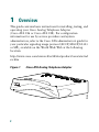
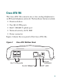
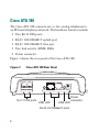
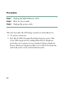
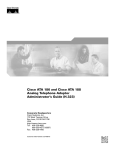
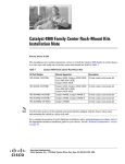
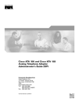
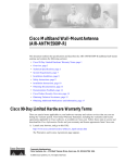
At A Glance
Cisco ATA 186 and Cisco ATA 188
Analog Telephone Adaptor
1
Overview
2
Installation
3
Configuration
1
Overview
This guide contains basic instructions for installing, testing, and
operating your Cisco Analog Telephone Adaptor
(Cisco ATA 186 or Cisco ATA 188). For configuration
information for use by service providers and system
administrators, refer to the Cisco ATA administrator’s guide for
your particular signaling image protocol (SCCP, MGCP, H.323
or SIP), available on the World Wide Web at the following
location:
http://www.cisco.com/univercd/cc/td/doc/product/voice/ata/ind
ex.htm
Figure 1
Cisco ATA Analog Telephone Adaptor
CISCO A
TA 186
TELEPH
ONE AD
APTOR
72209
ANALOG
2
Cisco ATA 186
The Cisco ATA 186 connects one or two analog telephones to
an IP-based telephony network. The hardware features include:
• Function button
• Two RJ-11 FXS ports
• RJ-45 10BASE-T uplink port
• Network activity (ACT) LED
• Power connector
Figure 2 shows the rear panel of the Cisco ATA 186.
Cisco ATA 186 Rear Panel
PHONE 1
PHONE 2
RJ-11 FXS ports
RJ-45 10BaseT
10BaseT
ACT
72210
Figure 2
5V
Power
connector
ACT LED
3
Cisco ATA 188
The Cisco ATA 188 connects one or two analog telephones to
an IP-based telephony network. The hardware features include:
• Two RJ-11 FXS ports
• RJ-45 10/100BASE-T uplink port
• RJ-45 10/100BASE-T data port
• Two link activity (LINK) LEDs
• Power connector
Figure 3 shows the rear panel of the Cisco ATA 188.
Cisco ATA 188 Rear Panel
PHONE 1
PHONE 2
RJ-11 FXS ports
LINK
10/100 PC
10/100 UPLINK LINK
5V
Power
connector
LINK LED
LINK LED
RJ-45 10/100BaseT ports
4
72211
Figure 3
Safety Recommendations
To ensure general safety, follow these guidelines:
• Do not open or disassemble this product.
• Do not get this product wet or pour liquids into this device.
• Do not perform any action that creates a potential hazard
to people or makes the equipment unsafe.
Warning
IMPORTANT SAFETY INSTRUCTIONS
This warning symbol means danger. You are in a situation that
could cause bodily injury. Before you work on any equipment, be
aware of the hazards involved with electrical circuitry and be
familiar with standard practices for preventing accidents. Use
the statement number provided at the end of each warning to
locate its translation in the translated safety warnings that
accompanied this device. Statement 1071
SAVE THESE INSTRUCTIONS
Waarschuwing BELANGRIJKE VEILIGHEIDSINSTRUCTIES
Dit waarschuwingssymbool betekent gevaar. U verkeert in een
situatie die lichamelijk letsel kan veroorzaken. Voordat u aan
enige apparatuur gaat werken, dient u zich bewust te zijn van de
bij elektrische schakelingen betrokken risico's en dient u op de
hoogte te zijn van de standaard praktijken om ongelukken te
5
voorkomen. Gebruik het nummer van de verklaring onderaan de
waarschuwing als u een vertaling van de waarschuwing die bij
het apparaat wordt geleverd, wilt raadplegen.
BEWAAR DEZE INSTRUCTIES
Varoitus
TÄRKEITÄ TURVALLISUUSOHJEITA
Tämä varoitusmerkki merkitsee vaaraa. Tilanne voi aiheuttaa
ruumiillisia vammoja. Ennen kuin käsittelet laitteistoa, huomioi
sähköpiirien käsittelemiseen liittyvät riskit ja tutustu
onnettomuuksien yleisiin ehkäisytapoihin.
Turvallisuusvaroitusten käännökset löytyvät laitteen mukana
toimitettujen käännettyjen turvallisuusvaroitusten joukosta
varoitusten lopussa näkyvien lausuntonumeroiden avulla.
SÄILYTÄ NÄMÄ OHJEET
Attention
IMPORTANTES INFORMATIONS DE SÉCURITÉ
Ce symbole d'avertissement indique un danger. Vous vous trouvez
dans une situation pouvant entraîner des blessures ou des
dommages corporels. Avant de travailler sur un équipement,
soyez conscient des dangers liés aux circuits électriques et
familiarisez-vous avec les procédures couramment utilisées pour
éviter les accidents. Pour prendre connaissance des traductions
des avertissements figurant dans les consignes de sécurité
traduites qui accompagnent cet appareil, référez-vous au numéro
de l'instruction situé à la fin de chaque avertissement.
CONSERVEZ CES INFORMATIONS
Warnung
WICHTIGE SICHERHEITSHINWEISE
Dieses Warnsymbol bedeutet Gefahr. Sie befinden sich in einer
Situation, die zu Verletzungen führen kann. Machen Sie sich vor
der Arbeit mit Geräten mit den Gefahren elektrischer Schaltungen
6
und den üblichen Verfahren zur Vorbeugung vor Unfällen vertraut.
Suchen Sie mit der am Ende jeder Warnung angegebenen
Anweisungsnummer nach der jeweiligen Übersetzung in den
übersetzten Sicherheitshinweisen, die zusammen mit diesem
Gerät ausgeliefert wurden.
BEWAHREN SIE DIESE HINWEISE GUT AUF.
Avvertenza
IMPORTANTI ISTRUZIONI SULLA SICUREZZA
Questo simbolo di avvertenza indica un pericolo. La situazione
potrebbe causare infortuni alle persone. Prima di intervenire su
qualsiasi apparecchiatura, occorre essere al corrente dei
pericoli relativi ai circuiti elettrici e conoscere le procedure
standard per la prevenzione di incidenti. Utilizzare il numero di
istruzione presente alla fine di ciascuna avvertenza per
individuare le traduzioni delle avvertenze riportate in questo
documento.
CONSERVARE QUESTE ISTRUZIONI
Advarsel
VIKTIGE SIKKERHETSINSTRUKSJONER
Dette advarselssymbolet betyr fare. Du er i en situasjon som kan
føre til skade på person. Før du begynner å arbeide med noe av
utstyret, må du være oppmerksom på farene forbundet med
elektriske kretser, og kjenne til standardprosedyrer for å
forhindre ulykker. Bruk nummeret i slutten av hver advarsel for å
finne oversettelsen i de oversatte sikkerhetsadvarslene som
fulgte med denne enheten.
TA VARE PÅ DISSE INSTRUKSJONENE
7
Aviso
INSTRUÇÕES IMPORTANTES DE SEGURANÇA
Este símbolo de aviso significa perigo. Você está em uma
situação que poderá ser causadora de lesões corporais. Antes de
iniciar a utilização de qualquer equipamento, tenha
conhecimento dos perigos envolvidos no manuseio de circuitos
elétricos e familiarize-se com as práticas habituais de prevenção
de acidentes. Utilize o número da instrução fornecido ao final de
cada aviso para localizar sua tradução nos avisos de segurança
traduzidos que acompanham este dispositivo.
GUARDE ESTAS INSTRUÇÕES
¡Advertencia! INSTRUCCIONES IMPORTANTES DE SEGURIDAD
Este símbolo de aviso indica peligro. Existe riesgo para su
integridad física. Antes de manipular cualquier equipo,
considere los riesgos de la corriente eléctrica y familiarícese
con los procedimientos estándar de prevención de accidentes. Al
final de cada advertencia encontrará el número que le ayudará a
encontrar el texto traducido en el apartado de traducciones que
acompaña a este dispositivo.
GUARDE ESTAS INSTRUCCIONES
Varning!
VIKTIGA SÄKERHETSANVISNINGAR
Denna varningssignal signalerar fara. Du befinner dig i en
situation som kan leda till personskada. Innan du utför arbete på
någon utrustning måste du vara medveten om farorna med
elkretsar och känna till vanliga förfaranden för att förebygga
olyckor. Använd det nummer som finns i slutet av varje varning för
att hitta dess översättning i de översatta säkerhetsvarningar som
medföljer denna anordning.
8
Warning
Ultimate disposal of this product should be handled
according to all national laws and regulations.
Warning
Read the installation instructions before you
connect the system to its power source.
Warning
This equipment contains a ring signal generator
(ringer), which is a source of hazardous voltage.
Do not touch the RJ-11 (phone) port wires
(conductors), the conductors of a cable connected
to the RJ-11 port, or the associated circuit-board
when the ringer is active. The ringer is activated
(indicated by a clicking sound) by an incoming
call.
Warning
The plug-socket combination must be accessible
at all times because it serves as the main
disconnecting device.
9
Warning
To avoid electric shock, do not connect safety
extra-low voltage (SELV) circuits to
telephone-network voltage (TNV) circuits. LAN
ports contain SELV circuits, and WAN ports
contain TNV circuits. Some LAN and WAN ports
both use RJ-45 connectors. Use caution when
connecting cables.
Warning
Do not work on the system or connect or
disconnect cables during periods of lightning
activity.
Warning
This equipment is to be installed and maintained
by service personnel only as defined by AS/NZS
3260 Clause 1.2.14.3 Service Personnel.
Caution
Read the instructions in the “Installation Steps”
section on page 13 before you connect the system
to its power source.
10
2
Installation
Installation Requirements
The analog telephone adaptor (ATA) package includes:
• Cisco ATA 186 or Cisco ATA 188 Analog Telephone
Adaptor
• Cisco ATA 186 and Cisco ATA 188 Analog Telephone
Adaptor At A Glance (this document)
• Regulatory Compliance and Safety Information for the
Cisco ATA 186 and Cisco ATA 188.
• 5V power adaptor
• Power cord
Caution
The Cisco ATA 186 and Cisco ATA 188 are
intended for use with a 5V DC power adapter only.
Use only the Cisco-approved power supply that
was provided with your ATA unit.
11
You also need the following items:
• Category-3 10BASE-T or 100BASE-T or better Ethernet
cable. One cable is needed for each Ethernet connection.
A Category-3 Ethernet cable supports 10BASE-T for up to
100 meters without quality degradation, and a Category-3
Ethernet cable supports 100BASE-T for up to 10 meters
without quality degradation.
For uplink connections, use a crossover Ethernet cable to
connect the Cisco ATA to another Ethernet device (such as a
router or PC) without using a hub. Otherwise, use
straight-through Ethernet cables for both uplink and data
port connections.
• Access to an IP network
• One or two analog Touch-Tone telephones or fax machines,
or one of each
12
Installation Steps
Figure 4 illustrates the cabling for the Cisco ATA 186. Figure 5
illustrates the cabling for the Cisco ATA 188.
Note
Before powering up the Cisco ATA, perform any
necessary configuration tasks. Refer to the Cisco ATA
administrator guide for your particular signaling image
protocol (SCCP, MGCP, H.323 or SIP), available on the
World Wide Web at the following location:
http://www.cisco.com/univercd/cc/td/doc/product/voic
e/ata/index.htm
13
Cabling the Cisco ATA 186
PHONE 1
PHONE 2
10BaseT
ACT
72212
Figure 4
5V
Power outlet
IP network
Analog telephones
(or fax)
5V power
adaptor
Power cord
14
Cabling the Cisco ATA 188
PHONE 1
PHONE 2
LINK
10/100 PC
10/100 UPLINK LINK
72213
Figure 5
5V
Power outlet
IP network
Analog telephones
(or fax)
PC
5V power
adaptor
Power cord
15
Refer to the appropriate illustration and follow these steps to
install your ATA:
Procedure
Step 1
Place the Cisco ATA near an electrical power outlet.
Step 2
Connect one end of a telephone line cord to the Phone
1 input on the rear panel of the Cisco ATA. Connect the
other end to an analog telephone set.
If you are connecting a telephone set that was
previously connected to an active telephone line,
unplug the telephone line cord from the wall jack and
plug it into the Phone 1 input.
Warning
16
To reduce the risk of fire, use only No. 26 AWG or
larger telecommunication line cord.
Do not connect the Phone input ports to a
telephone wall jack. To avoid damaging the
Cisco ATA or telephone wiring in the building, do
not connect the Cisco ATA to the
telecommunications network. Connect the Phone
port to a telephone only, never to a telephone wall
jack.
Caution
Note
Step 3
(Optional) Connect the telephone line cord of a second
telephone to the Phone 2 input port.
Note
Step 4
The telephone must be switched to tone setting (not
pulse) for the Cisco ATA to operate properly.
If you are connecting only one telephone to the
Cisco ATA, you must use the Phone 1 input port.
Connect an Ethernet cable to the uplink RJ-45
connector on the Cisco ATA. For the Cisco ATA 186,
this is the 10BASE-T connector; for the Cisco ATA 188,
this is the 10/100UPLINK connector.
17
Step 5
(Cisco ATA 188 only—optional) Connect a
straight-through Ethernet cable from your PC to the
10/100 PC RJ-45 connector on the Cisco ATA.
Step 6
Connect the socket end of the power cord to the 5V DC
power adaptor.
Step 7
Insert the power adaptor cable into the power
connector on the Cisco ATA.
Warning
18
This product relies on the building’s installation
for short-circuit (overcurrent) protection. Ensure
that a fuse or circuit breaker no larger than 120
VAC, 15A U.S. (240VAC, 10A international) is used
on the phase conductors (all current-carrying
conductors).
Step 8
Connect the plug end of the 5V DC power adaptor cord
into an electrical power outlet.
When the Cisco ATA is properly connected and
powered up, the green activity LED flashes to indicate
network activity. This LED is labeled ACT on the rear
panel of the Cisco ATA 186 and is labeled LINK on the
rear panel of the Cisco ATA 188.
Caution
Do not cover or block the air vents on either the
top or the bottom surface of the Cisco ATA.
Overheating can cause permanent damage to the
unit.
Power-Down Procedure
Caution
If you need to power down Cisco ATA 186 or
Cisco 188 at any time, use the following
power-down procedure to prevent damage to the
unit.
19
Procedure
Step 1
Unplug the RJ45 Ethernet cable
Step 2
Wait for 20 seconds.
Step 3
Unplug the power cable.
The unit provides the following connectors and indicators:
• 5V power connector.
• Two RJ-11 FXS (Foreign Exchange Station) ports—The
Cisco ATA supports two independent RJ-11 telephone
ports that can connect to any standard analog telephone
device. Each port supports either voice calls or fax sessions,
and both ports can be used simultaneously.
20
Note
The Cisco ATA186-I1 and Cisco ATA188-I1
provide 600-ohm resistive impedance. The
Cisco ATA186-I2 and Cisco ATA188-I2 provide
270 ohm + 750 ohm // 150-nF complex impedance.
The impedance option is requested when you place
your order and should match your specific
application. If you are not sure of the applicable
configuration, check your country or regional
telephone impedance requirements.
• Ethernet ports
– The Cisco ATA 186 has one RJ-45 10BASE-T uplink
Ethernet port to connect the Cisco ATA 186 to a
10/100BASE-T hub or another Ethernet device.
– The Cisco ATA 188 has two Ethernet ports: an RJ-45
10/100BASE-T uplink port to connect the
Cisco ATA 188 to a 10/100BASE-T hub or another
Ethernet device and an RJ-45 10/100BASE-T data port
to connect an Ethernet-capable device, such as a
computer, to the network.
21
Note
The Cisco ATA 188 performs auto-negotiation for
duplexity and speed and is capable of 10/100
Mbps, full-duplex operation. The Cisco ATA 186
is fixed at 10 Mbps, half-duplex operation.
• The Cisco ATA 188 RJ-45 LED shows network link and
activity. The LED blinks twice when the Cisco ATA is first
powered on, then turns off if there is no link or activity. The
LED blinks to show network activity and is solid when
there is a link.
• The Cisco ATA 186 RJ-45 LED is solid when the Cisco ATA
is powered on and blinks to show network activity.
• Function button—The function button is located on the top
panel of the unit (see Figure 6).
22
Figure 6
Cisco ATA Function Button
Function
button
CISCO
72214
ATA 186
ANALOG
TELEPH
ONE AD
APTOR
The function button lights when you pick up the handset of
a telephone attached to the Cisco ATA. The button blinks
quickly when the Cisco ATA is upgrading its configuration.
Note
If the function button blinks slowly, the Cisco ATA
cannot find the DHCP server. Check your Ethernet
connections and make sure the DHCP server is
available.
23
Pressing the function button allows you to access to the
voice configuration menu. For additional information
about the voice configuration menu, see the information
about the voice configuration menu in your administrator’s
guide.
Caution
3
Never press the function button during an upgrade
process. Doing so may interfere with the process
and may permanently disable the Cisco ATA.
Configuration
For complete configuration information, see the administrator’s
guide for the signaling image protocol you are using (SCCP,
MGCP, H.323 or SIP). The Cisco ATA administrator’s guides
are located at the following URL:
http://www.cisco.com/univercd/cc/td/doc/product/voice/ata/ata
admn/index.htm
24
Making a Call
Lift the telephone handset. Make a call as you normally do. You
will hear ringing if the called party is available. When the called
party answers, speak normally and hang up when finished. You
can cancel or discontinue your call at any time by hanging up
the handset. You can make a separate, simultaneous telephone
call by using the second handset connected to the ATA.
Note
Your service provider or system administrator might
offer a different dial plan. If you cannot place calls
using the preceding instructions, contact your service
provider or system administrator for assistance.
Troubleshooting Tips
The suggestions in this section are general troubleshooting tips.
• Make sure that the DHCP server is operating correctly.
Note that the function button blinks slowly when the
Cisco ATA attempts to acquire the DHCP configuration.
• If the green activity LED is not flashing after you connect
the Ethernet cable, make sure that both the power cord and
the Ethernet connection are secure.
25
• If there is no dial tone, make sure that the telephone line
cord from the telephone is plugged into the appropriate
port on the Cisco ATA. Make sure that your Cisco ATA is
properly registered on your Call Control system. Test
another phone; if this phone does not work either, there
may be a problem with the current configuration or with
the Cisco ATA.
• A busy tone indicates that the party you called is not
available. Try your call again later. A fast-busy tone
indicates that you dialed an invalid number.
• After power up, if the function button continues to blink
slowly, the Cisco ATA cannot locate the DHCP server.
Check the Ethernet connection and the availability of the
DHCP server.
• The DHCP server should show an incoming request from
the MAC address listed on the product label or given by the
voice prompt.
Note
26
Customers who obtained their equipment through
service providers, independent dealers and other third
parties must contact their equipment provider for
technical assistance.
27
CCVP, the Cisco logo, and the Cisco Square Bridge logo are trademarks of Cisco Systems, Inc.; Changing
the Way We Work, Live, Play, and Learn is a service mark of Cisco Systems, Inc.; and Access Registrar,
Aironet, BPX, Catalyst, CCDA, CCDP, CCIE, CCIP, CCNA, CCNP, CCSP, Cisco, the Cisco Certified
Internetwork Expert logo, Cisco IOS, Cisco Press, Cisco Systems, Cisco Systems Capital, the Cisco Systems
logo, Cisco Unity, Enterprise/Solver, EtherChannel, EtherFast, EtherSwitch, Fast Step, Follow Me
Browsing, FormShare, GigaDrive, HomeLink, Internet Quotient, IOS, iPhone, IP/TV, iQ Expertise, the iQ
logo, iQ Net Readiness Scorecard, iQuick Study, LightStream, Linksys, MeetingPlace, MGX, Networking
Academy, Network Registrar, PIX, ProConnect, ScriptShare, SMARTnet, StackWise, The Fastest Way to
Increase Your Internet Quotient, and TransPath are registered trademarks of Cisco Systems, Inc. and/or its
affiliates in the United States and certain other countries.
All other trademarks mentioned in this document or Website are the property of their respective owners.
The use of the word partner does not imply a partnership relationship between Cisco and any other
company. (0709R)
Printed in the USA on recycled paper containing 10% postconsumer waste.
78-15931-01