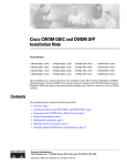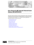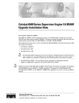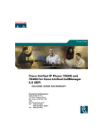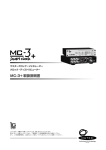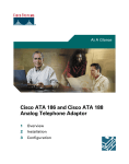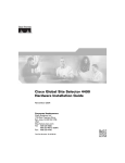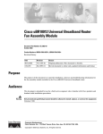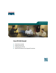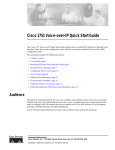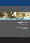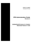
1
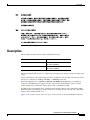
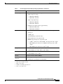
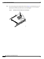
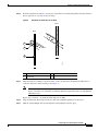
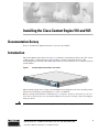
Installing the Cisco Content Engine 510 and 565
Documentation Survey
Is Cisco documentation helpful? Click here to give us your feedback.
Introduction
The Content Engine 510 and 565 (see Figure 1) are Internet content delivery devices that offer content
caching, hosting, content replication, video streaming, and other content-based services. The
Content Engine is positioned on the WAN edge between your small business site or enterprise network
and the Internet.
Content Engine 510 and 565—Front View
83284
Figure 1
This document explains how to install a Content Engine in an equipment rack. It also provides general
instructions for installing a Content Engine on a table or workbench.
Before you begin the installation, read the Regulatory Compliance and Safety Information for the Cisco
Content Networking Product Series document and the Site Preparation and Safety Guide that shipped
with your chassis.
Warning
Read the installation instructions before you connect the system to its power source.
Corporate Headquarters:
Cisco Systems, Inc., 170 West Tasman Drive, San Jose, CA 95134-1706 USA
Copyright © 2003 Cisco Systems, Inc. All rights reserved.
Contents
Contents
This document contains the following sections:
•
If You Need More Information, page 2
•
Warning Definition, page 3
•
Description, page 7
•
Installation Prerequisites, page 9
•
Safety Guidelines, page 10
•
Operating Specifications, page 12
•
Installing a Content Engine 510 or 565 Unit, page 14
•
Connecting Cables, page 19
•
Connecting Power and Booting the System, page 19
•
Checking the LEDs, page 20
•
Accessing the ACNS Software on the Content Engine, page 22
•
Removing or Replacing a Content Engine, page 23
•
Cisco One-Year Limited Hardware Warranty Terms, page 24
•
Obtaining Documentation, page 25
•
Obtaining Technical Assistance, page 26
•
Obtaining Additional Publications and Information, page 27
If You Need More Information
For additional information on the Cisco Content Engine 510 and 565 hardware, refer to the following
documentation:
•
Cisco Content Engine 510 and 565 Hardware Installation Guide
•
Installing Field-Replaceable Units in the Cisco Content Engine 510 and 565
For additional information on the Cisco ACNS software, refer to the following documentation:
•
For Cisco ACNS software Release 5.0:
– Release Notes for Cisco ACNS Software, Release 5.0
– Cisco ACNS Software Deployment and Configuration Guide, Release 5.0
– Cisco ACNS Software Caching Configuration Guide, Release 5.0
– Cisco ACNS Software Command Reference, Release 5.0
– SmartFilter for Cisco Content Engine User’s Guide, Version 3.1
•
For Cisco ACNS software, Release 5.1:
– Release Notes for Cisco ACNS Software, Release 5.1
– Cisco ACNS Software Deployment and Configuration Guide, Release 5.1
Installing the Cisco Content Engine 510 and 565
2
78-14731-02
Warning Definition
– Cisco ACNS Software Caching and Streaming Configuration Guide, Release 5.1
– Cisco ACNS Software Command Reference, Release 5.1
•
For information about configuring the Websense software, go to the following web site:
http://www.websense.com
•
For information about configuring the SmartFilter software, go to the following web site:
http://www.securecomputing.com
Warning Definition
Warning
IMPORTANT SAFETY INSTRUCTIONS
This warning symbol means danger. You are in a situation that could cause bodily injury. Before you
work on any equipment, be aware of the hazards involved with electrical circuitry and be familiar
with standard practices for preventing accidents. Use the statement number provided at the end of
each warning to locate its translation in the translated safety warnings that accompanied this
device. Statement 1071
SAVE THESE INSTRUCTIONS
Waarschuwing
BELANGRIJKE VEILIGHEIDSINSTRUCTIES
Dit waarschuwingssymbool betekent gevaar. U verkeert in een situatie die lichamelijk letsel kan
veroorzaken. Voordat u aan enige apparatuur gaat werken, dient u zich bewust te zijn van de bij
elektrische schakelingen betrokken risico's en dient u op de hoogte te zijn van de standaard
praktijken om ongelukken te voorkomen. Gebruik het nummer van de verklaring onderaan de
waarschuwing als u een vertaling van de waarschuwing die bij het apparaat wordt geleverd, wilt
raadplegen.
BEWAAR DEZE INSTRUCTIES
Varoitus
TÄRKEITÄ TURVALLISUUSOHJEITA
Tämä varoitusmerkki merkitsee vaaraa. Tilanne voi aiheuttaa ruumiillisia vammoja. Ennen kuin
käsittelet laitteistoa, huomioi sähköpiirien käsittelemiseen liittyvät riskit ja tutustu
onnettomuuksien yleisiin ehkäisytapoihin. Turvallisuusvaroitusten käännökset löytyvät laitteen
mukana toimitettujen käännettyjen turvallisuusvaroitusten joukosta varoitusten lopussa näkyvien
lausuntonumeroiden avulla.
SÄILYTÄ NÄMÄ OHJEET
Installing the Cisco Content Engine 510 and 565
78-14731-02
3
Warning Definition
Attention
IMPORTANTES INFORMATIONS DE SÉCURITÉ
Ce symbole d'avertissement indique un danger. Vous vous trouvez dans une situation pouvant
entraîner des blessures ou des dommages corporels. Avant de travailler sur un équipement, soyez
conscient des dangers liés aux circuits électriques et familiarisez-vous avec les procédures
couramment utilisées pour éviter les accidents. Pour prendre connaissance des traductions des
avertissements figurant dans les consignes de sécurité traduites qui accompagnent cet appareil,
référez-vous au numéro de l'instruction situé à la fin de chaque avertissement.
CONSERVEZ CES INFORMATIONS
Warnung
WICHTIGE SICHERHEITSHINWEISE
Dieses Warnsymbol bedeutet Gefahr. Sie befinden sich in einer Situation, die zu Verletzungen führen
kann. Machen Sie sich vor der Arbeit mit Geräten mit den Gefahren elektrischer Schaltungen und
den üblichen Verfahren zur Vorbeugung vor Unfällen vertraut. Suchen Sie mit der am Ende jeder
Warnung angegebenen Anweisungsnummer nach der jeweiligen Übersetzung in den übersetzten
Sicherheitshinweisen, die zusammen mit diesem Gerät ausgeliefert wurden.
BEWAHREN SIE DIESE HINWEISE GUT AUF.
Avvertenza
IMPORTANTI ISTRUZIONI SULLA SICUREZZA
Questo simbolo di avvertenza indica un pericolo. La situazione potrebbe causare infortuni alle
persone. Prima di intervenire su qualsiasi apparecchiatura, occorre essere al corrente dei pericoli
relativi ai circuiti elettrici e conoscere le procedure standard per la prevenzione di incidenti.
Utilizzare il numero di istruzione presente alla fine di ciascuna avvertenza per individuare le
traduzioni delle avvertenze riportate in questo documento.
CONSERVARE QUESTE ISTRUZIONI
Advarsel
VIKTIGE SIKKERHETSINSTRUKSJONER
Dette advarselssymbolet betyr fare. Du er i en situasjon som kan føre til skade på person. Før du
begynner å arbeide med noe av utstyret, må du være oppmerksom på farene forbundet med
elektriske kretser, og kjenne til standardprosedyrer for å forhindre ulykker. Bruk nummeret i slutten
av hver advarsel for å finne oversettelsen i de oversatte sikkerhetsadvarslene som fulgte med denne
enheten.
TA VARE PÅ DISSE INSTRUKSJONENE
Aviso
INSTRUÇÕES IMPORTANTES DE SEGURANÇA
Este símbolo de aviso significa perigo. Você está em uma situação que poderá ser causadora de
lesões corporais. Antes de iniciar a utilização de qualquer equipamento, tenha conhecimento dos
perigos envolvidos no manuseio de circuitos elétricos e familiarize-se com as práticas habituais de
prevenção de acidentes. Utilize o número da instrução fornecido ao final de cada aviso para
localizar sua tradução nos avisos de segurança traduzidos que acompanham este dispositivo.
GUARDE ESTAS INSTRUÇÕES
Installing the Cisco Content Engine 510 and 565
4
78-14731-02
Warning Definition
¡Advertencia!
INSTRUCCIONES IMPORTANTES DE SEGURIDAD
Este símbolo de aviso indica peligro. Existe riesgo para su integridad física. Antes de manipular
cualquier equipo, considere los riesgos de la corriente eléctrica y familiarícese con los
procedimientos estándar de prevención de accidentes. Al final de cada advertencia encontrará el
número que le ayudará a encontrar el texto traducido en el apartado de traducciones que acompaña
a este dispositivo.
GUARDE ESTAS INSTRUCCIONES
Varning!
VIKTIGA SÄKERHETSANVISNINGAR
Denna varningssignal signalerar fara. Du befinner dig i en situation som kan leda till personskada.
Innan du utför arbete på någon utrustning måste du vara medveten om farorna med elkretsar och
känna till vanliga förfaranden för att förebygga olyckor. Använd det nummer som finns i slutet av
varje varning för att hitta dess översättning i de översatta säkerhetsvarningar som medföljer denna
anordning.
SPARA DESSA ANVISNINGAR
Installing the Cisco Content Engine 510 and 565
78-14731-02
5
Warning Definition
Installing the Cisco Content Engine 510 and 565
6
78-14731-02
Description
Description
This document describes the following Content Engine models:
Model
Product Number
Content Engine 510
CE-510A-80GB-K9
CE-510A-160GB-K9
Content Engine 565
CE-565A-72GB-K9
CE-565A-144GB-K9
The Content Engine 510 and 565 are configured for AC-input power and have a single AC-input power
supply.
Your Content Engine comes with an integrated dual-port Ethernet controller. This controller provides an
interface for connecting to 10-Mbps, 100-Mbps, or 1000-Mbps networks.
The Content Engine has two 10BASE-T/100BASE-TX/1000BASE-TX Ethernet ports with RJ-45
receptacles. Both Ethernet ports support autodetect speed mode and full-duplex operation, which
enables simultaneous transmission and reception of data on the Ethernet LAN.
In addition, the Content Engine 565 is configured with one Ultra320 low voltage differential (LVD)
Small Computer System Interface (SCSI) connector for attaching the Cisco Storage Array. The SCSI
adapter card is installed in PCI slot 2.
Figure 2 calls out the locations of the slots, ports, and receptacles on the Content Engine back panel.
Installing the Cisco Content Engine 510 and 565
78-14731-02
7
Description
Figure 2
Content Engine 510 and 565 Back Panel
2
83108
1
9
8 7
6
5
4
3
1
AC power receptacle
2
PCI slot 1; Fibre Channel or MPEG A/V
decoder ports
3
Serial port
4
Ethernet 2 receptacle
5
Ethernet 1 receptacle
6
Onboard video port (not supported)
7
Mouse port (not supported)
8
Keyboard port (not supported)
9
PCI slot 2; SCSI adapter and port (CE-565
only)
Models can be configured with either a Fibre Channel card or an MPEG A/V decoder card. These cards
are user-replaceable and are installed in Peripheral Component Interconnect (PCI) slot 1 (labeled 2 in
Figure 2).
Figure 3 shows the Content Engine with a Fibre Channel card installed, and Figure 4 shows the
Content Engine with an MPEG A/V decoder card installed.
Content Engine 510 and 565 Back Panel—Fibre Channel Card Installed
Figure 4
Content Engine 510 and 565 Back Panel—MPEG A/V Decoder Card Installed
83286
83285
Figure 3
Installing the Cisco Content Engine 510 and 565
8
78-14731-02
Installation Prerequisites
Installation Prerequisites
Consider the following prerequisites before installing your Content Engine.
Tools and Parts Required
A sliding rail rack-mount kit and cable management assembly are included in your shipping container
accessory box. The rack-mount kit is suitable for mounting Content Engine 510 and 565 units in 19-inch
(48.26-cm) 4-post equipment racks.
Note
A 2-post rack-mounting option contains angle brackets for attaching the chassis to a 2-post rack.
You need the following tools for the installation:
•
Flat-blade screwdriver
•
Phillips screwdriver
Figure 5 shows the parts that you need to install the Content Engine in an equipment rack. If any parts
are missing or damaged, contact your place of purchase.
Figure 5
Rack Installation Kit
1
2
3
4
5
7
83198
6
Installing the Cisco Content Engine 510 and 565
78-14731-02
9
Safety Guidelines
Note
1
Slide rail assemblies (2)
2
M3.5 screws with lock washers (3)
3
M4 screws (6)
4
M6 screws (10)
5
Clip nuts (10)
6
Cage nuts (10)
7
Cage nut insertion tool (1)
The right and left slide rails are identical.
Safety Guidelines
To reduce the risk of bodily injury, electrical shock, fire, and damage to the equipment, observe the
following precautions.
Warning
Never defeat the ground conductor or operate the equipment in the absence of a suitably installed
ground conductor. Contact the appropriate electrical inspection authority or an electrician if you are
uncertain that suitable grounding is available.
Warning
The safety cover is an integral part of the product. Do not operate the unit without the safety cover
installed. Operating the unit without the cover in place will invalidate the safety approvals and pose
a risk of fire and electrical hazards.
Warning
Blank faceplates and cover panels serve three important functions: they prevent exposure to
hazardous voltages and currents inside the chassis; they contain electromagnetic interference (EMI)
that might disrupt other equipment; and they direct the flow of cooling air through the chassis. Do not
operate the system unless all cards, faceplates, front covers, and rear covers are in place.
Warning
Only trained and qualified personnel should be allowed to install, replace, or service this equipment.
Warning
This unit is intended for installation in restricted access areas. A restricted access area is where
access can only be gained by service personnel through the use of a special tool, lock and key, or
other means of security, and is controlled by the authority responsible for the location.
Warning
Class 1 laser product.
Installing the Cisco Content Engine 510 and 565
10
78-14731-02
Safety Guidelines
General Precautions
Observe the following general precautions for using and working with your system:
•
Observe and follow service markings. Do not service any Cisco product except as explained in your
system documentation. Opening or removing covers that are marked with the triangular symbol with
a lightning bolt may expose you to electrical shock. Components inside these compartments should
be serviced only by an authorized service technician.
•
If any of the following conditions occur, unplug the product from the electrical outlet and replace
the part, or contact your authorized service provider:
– The power cable, extension cord, or plug is damaged.
– An object has fallen into the product.
– The product has been exposed to water.
– The product has been dropped or damaged.
– The product does not operate correctly when you follow the operating instructions.
•
Keep your system components away from radiators and heat sources. Also, do not block cooling
vents.
•
Do not spill food or liquids on your system components, and never operate the product in a wet
environment.
•
Do not push any objects into the openings of your system components. Doing so can cause fire or
electric shock by shorting out interior components.
•
Use the product only with other Cisco-approved equipment.
•
Allow the product to cool before removing covers or touching internal components.
•
Use the correct external power source. Operate the product only from the type of power source
indicated on the electrical ratings label. If you are not sure of the type of power source required,
consult your service representative or local power company.
•
Use only approved power cables. If you have not been provided with a power cable for your
Content Engine or for any AC-powered option intended for your system, purchase a power cable that
is approved for use in your country. The power cable must be rated for the product and for the
voltage and current marked on the product’s electrical ratings label. The voltage and current rating
of the cable should be greater than the ratings marked on the product.
•
To help prevent electric shock, plug the system components and peripheral power cables into
properly grounded electrical outlets. These cables are equipped with three-prong plugs to help
ensure proper grounding. Do not use adapter plugs or remove the grounding prong from a cable. If
you must use an extension cord, use a three-wire cord with properly grounded plugs.
•
Observe extension cord and power strip ratings. Make sure that the total ampere rating of all
products plugged into the extension cord or power strip does not exceed 80 percent of the extension
cord or power strip ampere ratings limit.
•
Do not use appliance or voltage converters or kits sold for appliances with your product.
•
To help protect your system components from sudden, transient increases and decreases in electrical
power, use a surge suppressor, line conditioner, or uninterruptible power supply (UPS).
•
Position cables and power cords carefully; route cables and the power cord and plug so that they
cannot be stepped on or tripped over. Be sure that nothing rests on your system components’ cables
or power cord.
•
Do not modify power cables or plugs. Consult a licensed electrician or your power company for site
modifications. Always follow your local or national wiring rules.
Installing the Cisco Content Engine 510 and 565
78-14731-02
11
Operating Specifications
Protecting Against Electrostatic Discharge
Static electricity can harm delicate components inside your system. To prevent static damage, discharge
static electricity from your body before you touch any of your system’s electronic components. You can
do so by touching an unpainted metal surface on the chassis.
You can also take the following steps to prevent damage from electrostatic discharge (ESD):
•
When unpacking a static-sensitive component from its shipping carton, do not remove the
component from the antistatic packing material until you are ready to install the component in your
system. Just before unwrapping the antistatic packaging, be sure to discharge static electricity from
your body.
•
When transporting a sensitive component, first place it in an antistatic container or packaging.
•
Handle all sensitive components in a static-safe area. If possible, use antistatic floor pads and
workbench pads.
Rack-Mounting Considerations
Before installing your Content Engine in a rack, review the following guidelines:
•
Two or more people are required to install the device in a rack.
•
Ensure that the room air temperature is below 95°F (35°C).
•
Do not block any air vents; usually 6 inches (15 cm) of space provides proper airflow.
•
Plan the device installation starting from the bottom of the rack.
•
Install the heaviest device in the bottom of the rack.
•
Do not extend more than one device out of the rack at the same time.
•
Remove the rack doors and side panels to provide easier access during installation.
•
Connect the Content Engine to a properly grounded outlet.
•
Do not overload the power outlet when installing multiple devices in the rack.
•
Do not place any object weighing more than 110 lb (50 kg) on top of rack-mounted devices.
Operating Specifications
Table 1 describes the physical and operating specifications of the Content Engine 510 and 565.
Table 1
Content Engine 510 and 565 Operating Specifications
Specification
Dimensions
Description
•
Height: 1.75 in., 1 RU (44 mm)
•
Depth: 16.54 in. (420 mm)
•
Width: 16.69 in. (424 mm)
Weight
Maximum weight: 28 lb (12.7 kg) depending on your configuration
Power supply
203 watt (110 or 220 VAC auto-sensing)
Installing the Cisco Content Engine 510 and 565
12
78-14731-02
Operating Specifications
Table 1
Content Engine 510 and 565 Operating Specifications (continued)
Specification
Description
Electrical input
•
Sine-wave input (47–63 Hz) required
•
Input voltage low range:
– Minimum: 100 VAC
– Maximum: 127 VAC
•
Input voltage high range:
– Minimum: 200 VAC
– Maximum: 240 VAC
•
Input kilovolt-amperes (kVA), approximately:
– Minimum: 0.087 kVA
– Maximum: 0.150 kVA
Ports
•
10BASE-T, 100BASE-TX, 1000BASE-TX (dual) Ethernet ports
•
Serial port
•
2 USB1 ports
•
Ultra160 SCSI port (CE-565 only)
•
Fibre Channel port (on optional card)
•
MPEG A/V decoder port (on optional card):
– 3 BNC2 connectors for YUV, RGB3, and composite video output
– Mini-XLR 8-pin connector for S/PDIF4 and analog stereo audio
output
– Mini-XLR 8-pin connector for VGA5 output
Temperature
Humidity
Altitude
•
Content Engine on: 50 to 95°F (10 to 35°C)
•
Content Engine off: –40 to 140°F (–40 to +60°C)
•
Content Engine on: 8 to 80%
•
Content Engine off: 8 to 80%
Maximum altitude: 6500 ft (2000 m)
Acoustical noise
emissions
•
Sound power, idling: 6.5 bel maximum
•
Sound power, operating: 6.5 bel maximum
1. USB = Universal Serial Bus
2. BNC = Bayonet-Neill-Concelman
3. RGB = red green blue
4. S/PDIF = Sony/Phillips Digital Interface
5. VGA = video graphics array
Installing the Cisco Content Engine 510 and 565
78-14731-02
13
Installing a Content Engine 510 or 565 Unit
Installing a Content Engine 510 or 565 Unit
Place the unit in the desired location. You can mount it in a rack for your convenience, or place it on a
solid, stable surface. If you do not plan to install the Content Engine in an equipment rack, proceed to
the “Installing the Chassis on a Tabletop” section on page 18.
Racks are marked in vertical increments of 1.75 inches (4.44 cm). Each increment is referred to as a rack
unit (RU). A 1-RU device is 1.75 inches (4.44 cm) tall.
Warning
To prevent bodily injury when mounting or servicing this unit in a rack, you must take special
precautions to ensure that the system remains stable. The following guidelines are provided to ensure
your safety:
•
This unit should be mounted at the bottom of the rack if it is the only unit in the rack.
•
When mounting this unit in a partially filled rack, load the rack from the bottom to the top with the
heaviest component at the bottom of the rack.
•
If the rack is provided with stabilizing devices, install the stabilizers before mounting or servicing
the unit in the rack.
To install the Content Engine in the rack, follow these steps:
Step 1
Select a 1-RU-size location in the rack. Starting with the right front side of the rack (as viewed from the
front of the Content Engine), install a clip nut or cage nut in the top and bottom positions of the 1-RU
location that you selected (see Figure 6) and then install a clip nut or cage nut in the corresponding
positions on the rear of the rack.
Repeat this step for the left front side of the rack and the corresponding location on the rear of the rack.
Figure 6
Installing Clip Nuts or Cage Nuts
2
83200
1
1
Cage nuts
2
Clip nuts
Installing the Cisco Content Engine 510 and 565
14
78-14731-02
Installing a Content Engine 510 or 565 Unit
Step 2
Remove the inner slide rails (labeled 3 in Figure 7) from the slide rail assemblies by pressing the release
latches (labeled 2 in Figure 7) on the sides of the slide rail assemblies.
Figure 7
Removing the Inner Slide Rail
3
2
83202
1
1
Slide rail assembly
3
Inner slide rail
2
Release latch
Installing the Cisco Content Engine 510 and 565
78-14731-02
15
Installing a Content Engine 510 or 565 Unit
Step 3
Place an inner slide rail at the alignment marker (labeled 1 in Figure 8) as indicated by the arrow on the
side of the Content Engine. Use two M4 screws to secure the inner slide rail to the Content Engine.
Repeat this step to attach the other inner slide rail to the Content Engine.
Figure 8
Attaching the Inner Slide Rail to the Content Engine
83203
1
Installing the Cisco Content Engine 510 and 565
16
78-14731-02
Installing a Content Engine 510 or 565 Unit
Step 4
Insert the tab (labeled 1 in Figure 9) on the rear of the slide rail assembly through the center hole between
the two clip nuts or cage nuts on the rear flange.
Figure 9
Attaching the Slide Rails to the Rack
Front
Rear
1
2
83199
3
Step 5
1
Tab
3
Rear flange
2
Adjustment screw
Align the slide rail assembly to the front flange on the rack and insert and tighten two M6 screws to
secure the slide rail to the front flange. (See Figure 9.)
Note
If it is necessary to adjust the length of the slide rail, loosen the adjustment screw (labeled 2 in
Figure 9) in on the rear of the slide rail and then adjust the length of the slide rail and tighten the
adjustment screw.
Repeat Step 4 and Step 5 to install the other slide rail assembly.
Step 6
Align and insert the inner slide rails into the slide rail assemblies until they lock into place.
Step 7
Slide the Content Engine into the rack until the Content Engine locks into place.
Installing the Cisco Content Engine 510 and 565
78-14731-02
17
Installing a Content Engine 510 or 565 Unit
Step 8
Tighten the captive screw (labeled 1 in Figure 10) on each side of the front of the Content Engine to
secure the Content Engine to the rack.
Inserting the Inner Slide Rails
83201
Figure 10
1
Step 9
Attach the power cords and the Ethernet cables to the Content Engine. (See the “Connecting Cables”
section on page 19.)
Because the Content Engine does not contain cable retention brackets or cable strain relief brackets, you
must first bundle the external cables before you route them.
To remove the Content Engine from the rack, reverse these instructions. Store these installation
instructions with your Content Engine documentation for future use.
Installing the Chassis on a Tabletop
When you install a Content Engine on a workbench or tabletop, ensure that the surface is clean and in a
safe location and that you have considered the following:
•
The chassis should be installed off the floor. (Dust that accumulates on the floor is drawn into the
interior of the chassis by the cooling fans. Excessive dust inside the Content Engine can cause
overtemperature conditions and component failures.)
•
There must be approximately 19 inches (48.26 cm) of clearance at the front and rear of the chassis
for accessing network cables or equipment.
•
The Content Engine must receive adequate ventilation (it is not being installed in an enclosed
cabinet where ventilation is inadequate).
Installing the Cisco Content Engine 510 and 565
18
78-14731-02
Connecting Cables
Follow these steps to install the Content Engine on a workbench or tabletop:
Step 1
Remove any debris and dust from the tabletop or workbench, as well as from the surrounding area. Also
make sure that your path between the Content Engine and its new location is unobstructed.
Step 2
Attach the rubber feet to the bottom of the chassis. The rubber feet have an adhesive backing. Peel the
protective tape off the adhesive and stick the feet to the bottom of a clean chassis surface. Place one foot
in each corner.
Step 3
Place the chassis on the tabletop or workbench.
Step 4
Ensure that no exhaust air from other equipment is being drawn into the chassis. Also, ensure that there
is adequate clearance at the front and rear of the chassis.
Connecting Cables
Follow these steps to connect network, console, and SCSI cables to your Content Engine.
Note
The SCSI cable is part of the Cisco Storage Array accessory kit. If you did not order the Cisco
Storage Array, you did not receive a SCSI cable.
Step 1
For network connections, insert a Category 5 UTP cable into the Ethernet 1 or Ethernet 2 receptacle on
the Content Engine back panel. (See Figure 2.)
Step 2
Connect the other end of the network cable to a hub or switch in your network.
Step 3
For console connections, plug the serial cable into the serial port on the Content Engine back panel.
Step 4
Connect the other end of the console cable to a console or a communications server.
Step 5
If you are using a Cisco Storage Array as an external storage device, attach the SCSI cable to the SCSI
LVD port.
Caution
Step 6
Make sure to tighten the jackscrews on the SCSI cable.
Connect the other end of the SCSI cable to the appropriate port on your Storage Array.
For further information about the Cisco Storage Array, refer to the Cisco Storage Array Installation and
Configuration Guide publications.
Connecting Power and Booting the System
Follow these steps to connect power to your AC system:
Step 1
Review the information in the “Safety Guidelines” section on page 10.
Step 2
Plug the AC power cord into the power cord receptacle at the back of the Content Engine. (See Figure 2.)
Installing the Cisco Content Engine 510 and 565
78-14731-02
19
Checking the LEDs
Step 3
Connect the other end of the power cord to a power source at your installation site.
Step 4
Power up all externally connected devices.
Step 5
Press the power control button on the front of the Content Engine.
The system should begin booting. Once the operating system boots, you are ready to initialize the basic
software configuration. (Refer to the software configuration guide or user guide that shipped with your
system.)
While the Content Engine is powering up, the green power LED (labeled 4 in Figure 11) is on.
Note
Note
You can install a circular disk over the power control button to prevent accidental manual power down.
This disk, known as the power control button shield, comes with your Content Engine.
Checking the LEDs
When the Content Engine is up and running, observe the front and back panel LEDs to verify that your
system is operating properly.
Figure 11 shows the location of front panel LEDs, and Table 2 describes their function.
Figure 11
Front Panel LEDs
2
3
4
83109
1
Table 2
Front Panel LEDs
Indicator
Color
State
Description
1
CD-ROM drive activity Green
On
The CD-ROM drive is in use.
2
System error
On
A system error has occurred. An LED on the
diagnostic LED panel is also on to further
isolate the error.
3
Hard disk drive activity Green
Flashing
The associated hard disk drive is in use.
4
Power
On
Power is flowing to the Content Engine.
Flashing
The Content Engine is in standby mode.
Amber
Green
Figure 12 shows the location of back panel LEDs, and Table 3 describes the LED functions.
Installing the Cisco Content Engine 510 and 565
20
78-14731-02
Checking the LEDs
Figure 12
Back Panel LEDs
2
83110
1
6
Table 3
5
4
3
Back Panel LEDs
Indicator
Color
State
Description
1
Green
On
Indicates that the speed of the Ethernet LAN
is 1000BASE-TX.
Off
Indicates that the speed of the Ethernet LAN
is 10/100BASE-TX.
Ethernet 1 link
2
Ethernet 1 activity
Green
Blinking
Indicates that Ethernet port 1 has an active
connection to the LAN.
3
Ethernet 2 activity
Green
Blinking
Indicates that Ethernet port 2 has an active
connection to the LAN.
4
Ethernet 2 link
Green
On
Indicates that the speed of the Ethernet LAN
is 1000BASE-TX.
Off
Indicates that the speed of the Ethernet LAN
is 10/100BASE-TX.
5
Power
Green
On
Indicates that the Content Engine power
is on.
6
System Error
Amber
Blinking
Indicates a memory or fan error.
Figure 13 shows LEDs on the Fibre Channel card, and Table 4 describes the LED activity.
Fibre Channel Card LEDs
83287
Figure 13
Note
In the illustration, the top LED is green, and the bottom LED is amber.
Installing the Cisco Content Engine 510 and 565
78-14731-02
21
Accessing the ACNS Software on the Content Engine
Table 4
Fibre Channel Card LEDs
LED
State
Meaning
Green
On
Power is on.
Amber
On
Green
On
Amber
Off
Green
Off
Amber
On
Green
Off
Amber
Flashing
Green
Flashing
Amber
Flashing
Fibre Channel is on line.
Signal acquired (the Fibre Channel card firmware is
performing or waiting to perform Fibre Channel
loop initialization).
Loss of synchronization.
Firmware error.
Accessing the ACNS Software on the Content Engine
The Content Engine uses the Cisco Application and Content Networking System (ACNS) software for
configuration and deployment of an Application and Content Network (ACN). The ACNS software
includes both a graphical user interface, accessible through a web browser, and a command-line interface
(CLI), either of which can be used to configure the software. For more information about accessing and
configuring the ACNS software, refer to the Cisco ACNS Software Deployment and Configuration Guide
that is appropriate for the version of ACNS software running on your Content Engine.
To use the ACNS software CLI, you must connect to the Content Engine either through a Telnet session
from a PC, or by connecting a PC or terminal to the Content Engine console port.
Connecting a PC to the Content Engine
To access the ACNS software on the Content Engine through the console port on the Content Engine,
you must connect the Content Engine to a terminal or PC. The console cable and adapter required for
this connection are included with the Content Engine.
To connect to the Content Engine using a PC, the PC must have some type of terminal emulation
software installed. The terminal emulation software should be configured with the following parameters:
•
9600 baud
•
8 data bits
•
No parity bits
•
1 stop bit
Installing the Cisco Content Engine 510 and 565
22
78-14731-02
Removing or Replacing a Content Engine
To connect the Content Engine to a terminal or PC, follow these steps:
Step 1
Connect the blue console cable to the blue console port on the back of the Content Engine.
Step 2
Connect the DB-9 end of the console cable to the console port (also called the serial port) on your PC.
If this adapter does not fit your PC console port, you must provide an adapter that fits.
Removing or Replacing a Content Engine
Warning
Before working on a system that has an On/Off switch, turn OFF the power and unplug the power cord.
Warning
Ultimate disposal of this product should be handled according to all national laws and regulations.
To remove a Content Engine from your network, power it down, disconnect the power cords and network
cables, and physically remove the chassis from the rack.
The Content Engine is in constant communication with the router on your network; thus, when the router
notices that the Content Engine is no longer responding to it, the router stops sending requests to the
Content Engine. This is transparent to users. If other Content Engines are attached to the router, the
router continues sending requests to the other Content Engines.
When you remove a Content Engine, the pages that were cached on that device are no longer available
to the router or other Content Engines. Thus, you might see an increase in outgoing web traffic that might
have otherwise been fulfilled by the Content Engine that you are removing. However, after a time, the
router and other Content Engines redistribute the load of web traffic.
If you remove the last Content Engine from your network, you can also disable cache support on the
router. However, this is not necessary; having cache support enabled when there are no Content Engines
attached has no effect on the router’s performance.
To replace a Content Engine, remove it from the network. Then, install a new Content Engine and
configure it using the same configuration parameters (IP address, and so forth) that you used for the
removed Content Engine.
Installing the Cisco Content Engine 510 and 565
78-14731-02
23
Cisco One-Year Limited Hardware Warranty Terms
Cisco One-Year Limited Hardware Warranty Terms
There are special terms applicable to your hardware warranty and various services that you can use
during the warranty period. Your formal Warranty Statement, including the warranty applicable to Cisco
software, is included on the CD that accompanies your Cisco product. Follow these steps to access and
download the Cisco Information Packet and your warranty document from the CD or from Cisco.com.
1.
Launch your browser, and go to this URL:
http://www.cisco.com/univercd/cc/td/doc/es_inpck/cetrans.htm
The Warranties and License Agreements page appears.
2.
To read the Cisco Information Packet, follow these steps:
a. Click the Information Packet Number field, and make sure that the part number
78-5235-02C0 is highlighted.
b. Select the language in which you would like to read the document.
c. Click Go.
The Cisco Limited Warranty and Software License page from the Information Packet appears.
d. Read the document online, or click the PDF icon to download and print the document in PDF
format (Adobe Portable Data File).
Note
3.
You must have Adobe Acrobat Reader to view and print PDF files. You can download
the reader from Adobe’s website: http://www.adobe.com
To read translated and localized warranty information about your product, follow these steps:
a. Enter this part number in the Warranty Document Number field:
78-10747-01C0
b. Select the language in which you would like to view the document.
c. Click Go.
The Cisco warranty page appears.
d. Read the document online, or click the PDF icon to download and print the document in PDF
format (Adobe Portable Data File).
You can also contact the Cisco service and support website for assistance:
http://www.cisco.com/public/Support_root.shtml.
Duration of Hardware Warranty
One (1) Year
Replacement, Repair, or Refund Policy for Hardware
Cisco or its service center will use commercially reasonable efforts to ship a replacement part within ten
(10) working days after receipt of a Return Materials Authorization (RMA) request. Actual delivery
times can vary, depending on the customer location.
Cisco reserves the right to refund the purchase price as its exclusive warranty remedy.
Installing the Cisco Content Engine 510 and 565
24
78-14731-02
Obtaining Documentation
To Receive a Return Materials Authorization (RMA) Number
Contact the company from whom you purchased the product. If you purchased the product directly from
Cisco, contact your Cisco Sales and Service Representative.
Complete the information below, and keep it for reference.
Company product purchased from
Company telephone number
Product model number
Product serial number
Maintenance contract number
Obtaining Documentation
Cisco provides several ways to obtain documentation, technical assistance, and other technical
resources. These sections explain how to obtain technical information from Cisco Systems.
Cisco.com
You can access the most current Cisco documentation on the World Wide Web at this URL:
http://www.cisco.com/univercd/home/home.htm
You can access the Cisco website at this URL:
http://www.cisco.com
International Cisco websites can be accessed from this URL:
http://www.cisco.com/public/countries_languages.shtml
Documentation CD-ROM
Cisco documentation and additional literature are available in a Cisco Documentation CD-ROM
package, which may have shipped with your product. The Documentation CD-ROM is updated regularly
and may be more current than printed documentation. The CD-ROM package is available as a single unit
or through an annual or quarterly subscription.
Registered Cisco.com users can order a single Documentation CD-ROM (product number
DOC-CONDOCCD=) through the Cisco Ordering tool:
http://www.cisco.com/en/US/partner/ordering/ordering_place_order_ordering_tool_launch.html
All users can order annual or quarterly subscriptions through the online Subscription Store:
http://www.cisco.com/go/subscription
Installing the Cisco Content Engine 510 and 565
78-14731-02
25
Obtaining Technical Assistance
Ordering Documentation
You can find instructions for ordering documentation at this URL:
http://www.cisco.com/univercd/cc/td/doc/es_inpck/pdi.htm
You can order Cisco documentation in these ways:
•
Registered Cisco.com users (Cisco direct customers) can order Cisco product documentation from
the Networking Products MarketPlace:
http://www.cisco.com/en/US/partner/ordering/index.shtml
•
Nonregistered Cisco.com users can order documentation through a local account representative by
calling Cisco Systems Corporate Headquarters (California, USA.) at 408 526-7208 or, elsewhere in
North America, by calling 800 553-NETS (6387).
Documentation Feedback
You can submit comments electronically on Cisco.com. On the Cisco Documentation home page, click
Feedback at the top of the page.
You can send your comments in e-mail to [email protected].
You can submit comments by using the response card (if present) behind the front cover of your
document or by writing to the following address:
Cisco Systems
Attn: Customer Document Ordering
170 West Tasman Drive
San Jose, CA 95134-9883
We appreciate your comments.
Obtaining Technical Assistance
For all customers, partners, resellers, and distributors who hold valid Cisco service contracts, the Cisco
Technical Assistance Center (TAC) provides 24-hour, award-winning technical support services, online
and over the phone. Cisco.com features the Cisco TAC website as an online starting point for technical
assistance.
Cisco TAC Website
The Cisco TAC website (http://www.cisco.com/tac) provides online documents and tools for
troubleshooting and resolving technical issues with Cisco products and technologies. The Cisco TAC
website is available 24 hours a day, 365 days a year.
Accessing all the tools on the Cisco TAC website requires a Cisco.com user ID and password. If you
have a valid service contract but do not have a login ID or password, register at this URL:
http://tools.cisco.com/RPF/register/register.do
Installing the Cisco Content Engine 510 and 565
26
78-14731-02
Obtaining Additional Publications and Information
Opening a TAC Case
The online TAC Case Open Tool (http://www.cisco.com/tac/caseopen) is the fastest way to open P3 and
P4 cases. (Your network is minimally impaired or you require product information). After you describe
your situation, the TAC Case Open Tool automatically recommends resources for an immediate solution.
If your issue is not resolved using these recommendations, your case will be assigned to a Cisco TAC
engineer.
For P1 or P2 cases (your production network is down or severely degraded) or if you do not have Internet
access, contact Cisco TAC by telephone. Cisco TAC engineers are assigned immediately to P1 and P2
cases to help keep your business operations running smoothly.
To open a case by telephone, use one of the following numbers:
Asia-Pacific: +61 2 8446 7411 (Australia: 1 800 805 227)
EMEA: +32 2 704 55 55
USA: 1 800 553-2447
For a complete listing of Cisco TAC contacts, go to this URL:
http://www.cisco.com/warp/public/687/Directory/DirTAC.shtml
TAC Case Priority Definitions
To ensure that all cases are reported in a standard format, Cisco has established case priority definitions.
Priority 1 (P1)—Your network is “down” or there is a critical impact to your business operations. You
and Cisco will commit all necessary resources around the clock to resolve the situation.
Priority 2 (P2)—Operation of an existing network is severely degraded, or significant aspects of your
business operation are negatively affected by inadequate performance of Cisco products. You and Cisco
will commit full-time resources during normal business hours to resolve the situation.
Priority 3 (P3)—Operational performance of your network is impaired, but most business operations
remain functional. You and Cisco will commit resources during normal business hours to restore service
to satisfactory levels.
Priority 4 (P4)—You require information or assistance with Cisco product capabilities, installation, or
configuration. There is little or no effect on your business operations.
Obtaining Additional Publications and Information
Information about Cisco products, technologies, and network solutions is available from various online
and printed sources.
•
The Cisco Product Catalog describes the networking products offered by Cisco Systems, as well as
ordering and customer support services. Access the Cisco Product Catalog at this URL:
http://www.cisco.com/en/US/products/products_catalog_links_launch.html
•
Cisco Press publishes a wide range of networking publications. Cisco suggests these titles for new
and experienced users: Internetworking Terms and Acronyms Dictionary, Internetworking
Technology Handbook, Internetworking Troubleshooting Guide, and the Internetworking Design
Guide. For current Cisco Press titles and other information, go to Cisco Press online at this URL:
http://www.ciscopress.com
Installing the Cisco Content Engine 510 and 565
78-14731-02
27
Obtaining Additional Publications and Information
•
Packet magazine is the Cisco quarterly publication that provides the latest networking trends,
technology breakthroughs, and Cisco products and solutions to help industry professionals get the
most from their networking investment. Included are networking deployment and troubleshooting
tips, configuration examples, customer case studies, tutorials and training, certification information,
and links to numerous in-depth online resources. You can access Packet magazine at this URL:
http://www.cisco.com/go/packet
•
iQ Magazine is the Cisco bimonthly publication that delivers the latest information about Internet
business strategies for executives. You can access iQ Magazine at this URL:
http://www.cisco.com/go/iqmagazine
•
Internet Protocol Journal is a quarterly journal published by Cisco Systems for engineering
professionals involved in designing, developing, and operating public and private internets and
intranets. You can access the Internet Protocol Journal at this URL:
http://www.cisco.com/en/US/about/ac123/ac147/about_cisco_the_internet_protocol_journal.html
•
Training—Cisco offers world-class networking training. Current offerings in network training are
listed at this URL:
http://www.cisco.com/en/US/learning/index.html
This document is to be used in conjunction with the Cisco Content Engine 510 and 565 Hardware Installation Guide.
CCIP, CCSP, the Cisco Arrow logo, the Cisco Powered Network mark, Cisco Unity, Follow Me Browsing, FormShare, and StackWise are trademarks
of Cisco Systems, Inc.; Changing the Way We Work, Live, Play, and Learn, and iQuick Study are service marks of Cisco Systems, Inc.; and Aironet,
ASIST, BPX, Catalyst, CCDA, CCDP, CCIE, CCNA, CCNP, Cisco, the Cisco Certified Internetwork Expert logo, Cisco IOS, the Cisco IOS logo,
Cisco Press, Cisco Systems, Cisco Systems Capital, the Cisco Systems logo, Empowering the Internet Generation, Enterprise/Solver, EtherChannel,
EtherSwitch, Fast Step, GigaStack, Internet Quotient, IOS, IP/TV, iQ Expertise, the iQ logo, iQ Net Readiness Scorecard, LightStream, MGX,
MICA, the Networkers logo, Networking Academy, Network Registrar, Packet, PIX, Post-Routing, Pre-Routing, RateMUX, Registrar, ScriptShare,
SlideCast, SMARTnet, StrataView Plus, Stratm, SwitchProbe, TeleRouter, The Fastest Way to Increase Your Internet Quotient, TransPath, and VCO
are registered trademarks of Cisco Systems, Inc. and/or its affiliates in the U.S. and certain other countries.
All other trademarks mentioned in this document or Web site are the property of their respective owners. The use of the word partner does not imply
a partnership relationship between Cisco and any other company. (0304R)
Copyright © 2003 Cisco Systems, Inc.
All rights reserved.
Installing the Cisco Content Engine 510 and 565
28
78-14731-02