1
Cisco ATA 186 and Cisco ATA 188
Analog Telephone Adaptor
Administrator’s Guide (H.323)
Corporate Headquarters
Cisco Systems, Inc.
170 West Tasman Drive
San Jose, CA 95134-1706
USA
http://www.cisco.com
Tel: 408 526-4000
800 553-NETS (6387)
Fax: 408 526-4100
Customer Order Number: OL-4008-01
THE SPECIFICATIONS AND INFORMATION REGARDING THE PRODUCTS IN THIS MANUAL ARE SUBJECT TO CHANGE WITHOUT NOTICE. ALL
STATEMENTS, INFORMATION, AND RECOMMENDATIONS IN THIS MANUAL ARE BELIEVED TO BE ACCURATE BUT ARE PRESENTED WITHOUT
WARRANTY OF ANY KIND, EXPRESS OR IMPLIED. USERS MUST TAKE FULL RESPONSIBILITY FOR THEIR APPLICATION OF ANY PRODUCTS.
THE SOFTWARE LICENSE AND LIMITED WARRANTY FOR THE ACCOMPANYING PRODUCT ARE SET FORTH IN THE INFORMATION PACKET THAT
SHIPPED WITH THE PRODUCT AND ARE INCORPORATED HEREIN BY THIS REFERENCE. IF YOU ARE UNABLE TO LOCATE THE SOFTWARE LICENSE
OR LIMITED WARRANTY, CONTACT YOUR CISCO REPRESENTATIVE FOR A COPY.
The following information is for FCC compliance of Class A devices: This equipment has been tested and found to comply with the limits for a Class A digital device, pursuant
to part 15 of the FCC rules. These limits are designed to provide reasonable protection against harmful interference when the equipment is operated in a commercial
environment. This equipment generates, uses, and can radiate radio-frequency energy and, if not installed and used in accordance with the instruction manual, may cause
harmful interference to radio communications. Operation of this equipment in a residential area is likely to cause harmful interference, in which case users will be required
to correct the interference at their own expense.
The following information is for FCC compliance of Class B devices: The equipment described in this manual generates and may radiate radio-frequency energy. If it is not
installed in accordance with Cisco’s installation instructions, it may cause interference with radio and television reception. This equipment has been tested and found to
comply with the limits for a Class B digital device in accordance with the specifications in part 15 of the FCC rules. These specifications are designed to provide reasonable
protection against such interference in a residential installation. However, there is no guarantee that interference will not occur in a particular installation.
Modifying the equipment without Cisco’s written authorization may result in the equipment no longer complying with FCC requirements for Class A or Class B digital
devices. In that event, your right to use the equipment may be limited by FCC regulations, and you may be required to correct any interference to radio or television
communications at your own expense.
You can determine whether your equipment is causing interference by turning it off. If the interference stops, it was probably caused by the Cisco equipment or one of its
peripheral devices. If the equipment causes interference to radio or television reception, try to correct the interference by using one or more of the following measures:
• Turn the television or radio antenna until the interference stops.
• Move the equipment to one side or the other of the television or radio.
• Move the equipment farther away from the television or radio.
• Plug the equipment into an outlet that is on a different circuit from the television or radio. (That is, make certain the equipment and the television or radio are on circuits
controlled by different circuit breakers or fuses.)
Modifications to this product not authorized by Cisco Systems, Inc. could void the FCC approval and negate your authority to operate the product.
NOTWITHSTANDING ANY OTHER WARRANTY HEREIN, ALL DOCUMENT FILES AND SOFTWARE OF THESE SUPPLIERS ARE PROVIDED “AS IS” WITH
ALL FAULTS. CISCO AND THE ABOVE-NAMED SUPPLIERS DISCLAIM ALL WARRANTIES, EXPRESSED OR IMPLIED, INCLUDING, WITHOUT
LIMITATION, THOSE OF MERCHANTABILITY, FITNESS FOR A PARTICULAR PURPOSE AND NONINFRINGEMENT OR ARISING FROM A COURSE OF
DEALING, USAGE, OR TRADE PRACTICE.
IN NO EVENT SHALL CISCO OR ITS SUPPLIERS BE LIABLE FOR ANY INDIRECT, SPECIAL, CONSEQUENTIAL, OR INCIDENTAL DAMAGES, INCLUDING,
WITHOUT LIMITATION, LOST PROFITS OR LOSS OR DAMAGE TO DATA ARISING OUT OF THE USE OR INABILITY TO USE THIS MANUAL, EVEN IF CISCO
OR ITS SUPPLIERS HAVE BEEN ADVISED OF THE POSSIBILITY OF SUCH DAMAGES.
CCIP, CCSP, the Cisco Arrow logo, the Cisco Powered Network mark, the Cisco Systems Verified logo, Cisco Unity, Follow Me Browsing, FormShare, iQ Net Readiness
Scorecard, Networking Academy, and ScriptShare are trademarks of Cisco Systems, Inc.; Changing the Way We Work, Live, Play, and Learn, The Fastest Way to Increase
Your Internet Quotient, and iQuick Study are service marks of Cisco Systems, Inc.; and Aironet, ASIST, BPX, Catalyst, CCDA, CCDP, CCIE, CCNA, CCNP, Cisco, the
Cisco Certified Internetwork Expert logo, Cisco IOS, the Cisco IOS logo, Cisco Press, Cisco Systems, Cisco Systems Capital, the Cisco Systems logo, Empowering the
Internet Generation, Enterprise/Solver, EtherChannel, EtherSwitch, Fast Step, GigaStack, Internet Quotient, IOS, IP/TV, iQ Expertise, the iQ logo, LightStream, MGX,
MICA, the Networkers logo, Network Registrar, Packet, PIX, Post-Routing, Pre-Routing, RateMUX, Registrar, SlideCast, SMARTnet, StrataView Plus, Stratm, SwitchProbe,
TeleRouter, TransPath, and VCO are registered trademarks of Cisco Systems, Inc. and/or its affiliates in the U.S. and certain other countries.
All other trademarks mentioned in this document or Web site are the property of their respective owners. The use of the word partner does not imply a partnership relationship
between Cisco and any other company. (0303R)
Cisco ATA 186 and Cisco ATA 188 Analog Telephone Adaptor Administrator’s Guide (H.323)
Copyright © 2003, Cisco Systems, Inc.
All rights reserved.
C O N T E N T S
Preface
xi
Overview
xi
Audience
xi
Organization
xii
Conventions
xii
Related Documentation
xiv
Obtaining Documentation xv
World Wide Web xv
Documentation CD-ROM xv
Ordering Documentation xv
Documentation Feedback xv
Obtaining Technical Assistance xvi
Cisco.com xvi
Technical Assistance Center xvi
Cisco TAC Web Site xvii
Cisco TAC Escalation Center xvii
CHAPTER
1
Cisco Analog Telephone Adaptor Overview
1-1
H.323 Overview 1-2
H.323 Terminals 1-3
H.323 Gateways 1-3
H.323 Gatekeepers 1-4
H.323 MCUs 1-4
H.323 Proxy Server 1-4
Hardware Overview
1-5
Software Features 1-7
Voice Codecs Supported 1-7
Additional Supported Signaling Protocols
Other Supported Protocols 1-7
Cisco ATA H.323 Services 1-8
Fax Services 1-9
Supplementary Services 1-9
Installation and Configuration Overview
1-7
1-9
Cisco ATA 186 and Cisco ATA 188 Analog Telephone Adaptor Administrator’s Guide (H.323)
OL-4008-01
iii
Contents
CHAPTER
2
Installing the Cisco ATA
2-1
Safety Recommendations
2-1
What the Cisco ATA Package Includes
What You Need
2-2
Installation Procedure
Power-Down Procedure
CHAPTER
3
2-2
2-2
2-5
Configuring the Cisco ATA for H.323
Default Boot Load Behavior
3-1
3-2
Specifying a Preconfigured VLAN ID or Disabling VLAN IP Encapsulation
3-3
Steps Needed to Configure the Cisco ATA 3-5
Basic Configuration Steps in a TFTP Server Environment 3-5
Basic Configuration Steps in a Non-TFTP Server Environment 3-6
Configuring the Cisco ATA Using a TFTP Server 3-7
Setting Up the TFTP Server with Cisco ATA Software 3-7
Configurable Features and Related Parameters 3-7
Creating Unique and Common Cisco ATA Configuration Files 3-8
Using atapname.exe Tool to Obtain MAC Address 3-10
Using the EncryptKey Parameter and cfgfmt Tool 3-11
atadefault.cfg Configuration File 3-12
Configuring the Cisco ATA to Obtain its Configuration File from the TFTP Server
Using a DHCP Server 3-13
Without Using a DHCP Server 3-14
Voice Configuration Menu 3-15
Using the Voice Configuration Menu 3-16
Entering Alphanumeric Values 3-17
Resetting the Cisco ATA to Factory Default Values
Cisco ATA Web Configuration Page
3-18
3-18
Web Interface Access-Control Configuration
3-20
Refreshing or Resetting the Cisco ATA 3-20
HTTP Procedure to Refresh the Cisco ATA 3-21
HTTP Procedure to Reset the Cisco ATA 3-21
HTTP Refresh and Reset Access-Control Configuration
Upgrading the H.323 Signaling Image
CHAPTER
4
Basic and Additional H.323 Services
Important Basic H.323 Services
Required Parameters 4-1
3-12
3-21
3-21
4-1
4-1
Cisco ATA 186 and Cisco ATA 188 Analog Telephone Adaptor Administrator’s Guide (H.323)
iv
OL-4008-01
Contents
Setting the Signaling Image to H.323 Mode 4-2
Setting Up User IDs for the Cisco ATA 4-3
Using the Cisco ATA with an H.323 Gatekeeper 4-3
Choosing Cisco ATA Registration Mode with an H.323 Gatekeeper 4-3
Setting Up Gatekeeper Time-To-Live Value 4-4
Setting Up an Alternate H.323 Gatekeeper 4-4
Establishing Authentication with Cisco H.323 Gatekeeper 4-5
Using the Cisco ATA Without an H.323 Gatekeeper 4-6
Using the Cisco ATA With an H.323 Gateway but Without an H.323 Gatekeeper
Using Multiple Cisco ATAs Without an H.323 Gatekeeper 4-6
Setting the Audio Codecs 4-7
4-6
Additional H.323 Services 4-7
Configuring Audio Packet Settings 4-8
Configuring Billable Features 4-8
Configuring the Call Waiting Permanent Default Setting 4-9
Configuring the Cisco ATA Refresh Interval 4-9
Configuring Hook Flash Timing 4-9
Configuring the Mixing of Call Waiting Tone and Audio 4-9
Configuring Network Ringback Tone 4-9
Configuring On-hook delay 4-10
Configuring Reverse Audio Cut-Through Behavior 4-10
Configuring Supplementary Service Behavior and Parameters 4-10
Debugging Diagnostics 4-10
Hardware Information Display 4-10
Network Timing 4-11
Polarity Settings 4-11
Progress Tones 4-11
Selecting DTMF and Hookflash Transmission Methods 4-11
Selecting H.323 Connection and H.245 Transmission Methods 4-12
Setting Dial Plans 4-12
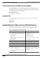
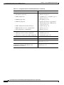
Complete Reference Table of all Cisco ATA H.323 Services
CHAPTER
5
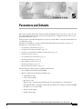
Parameters and Defaults
4-12
5-1
Configuration Text File Template
User Interface (UI) Parameter
UIPassword 5-3
5-2
5-3
Configuration-Complete Parameter
ToConfig 5-4
5-4
Parameters for Configuration Method and Encryption
5-4
Cisco ATA 186 and Cisco ATA 188 Analog Telephone Adaptor Administrator’s Guide (H.323)
OL-4008-01
v
Contents
UseTFTP 5-5
TftpURL 5-5
CfgInterval 5-6
EncryptKey 5-6
Network Parameters 5-7
DHCP 5-7
StaticIp 5-8
StaticRoute 5-8
StaticNetMask 5-9
Account Information Parameters
UID0 5-10
PWD0 5-10
UID1 5-11
PWD1 5-12
Gateway 5-12
UseLoginID 5-13
LoginID0 5-13
LoginID1 5-14
AutMethod 5-14
5-9
Gatekeeper Parameters 5-15
GkOrProxy 5-15
AltGk 5-16
AltGkTimeOut 5-16
GkTimeToLive 5-17
GkId 5-17
H.323 Mode Parameter
UseSIP 5-18
5-18
Operating Parameters 5-18
MediaPort 5-19
LBRCodec 5-19
AudioMode 5-20
RxCodec 5-21
TxCodec 5-22
NumTxFrames 5-23
CallFeatures 5-24
PaidFeatures 5-25
CallerIdMethod 5-26
Polarity 5-27
ConnectMode 5-28
Cisco ATA 186 and Cisco ATA 188 Analog Telephone Adaptor Administrator’s Guide (H.323)
vi
OL-4008-01
Contents
TimeZone 5-29
NTPIP 5-30
AltNTPIP 5-30
DNS1IP 5-31
DNS2IP 5-31
UDPTOS 5-31
SigTimer 5-32
OpFlags 5-33
VLANSetting 5-34
Optional Feature Parameters 5-35
NPrintf 5-35
RingOnOffTime 5-36
IPDialPlan 5-36
DialPlan 5-37
About Dial Plan Commands 5-38
Dial Plan Blocking (In Rule) 5-39
'H' Rule to Support Hotline/Warmline 5-40
'P' Rule to Support Dial Prefix 5-40
Call-Progress Tone Parameters 5-41
List of Call-Progress Tone Parameters 5-41
Tone Parameter Syntax 5-41
How to Calculate Scaling Factors 5-42
Recommended Values 5-42
Specific Call-Progress Tone Parameter Information
CallCmd 5-46
CHAPTER
6
Call Commands
6-1
Call Command Structure
6-1
Syntax 6-2
Context-Identifiers 6-3
Input Sequence Identifiers
Action Identifiers 6-4
CHAPTER
7
5-43
Call Command Example
6-5
Call Command Behavior
6-7
6-4
Configuring and Debugging Fax Services
7-1
Using Fax Pass-through Mode 7-1
Configuring the Cisco ATA for Fax Pass-through mode
AudioMode 7-2
7-2
Cisco ATA 186 and Cisco ATA 188 Analog Telephone Adaptor Administrator’s Guide (H.323)
OL-4008-01
vii
Contents
ConnectMode 7-3
Configuring Cisco IOS Gateways to Enable Fax Pass-through
Enable Fax Pass-through Mode 7-4
Disable Fax Relay Feature 7-5
Using FAX Mode 7-6
Configuring the Cisco ATA for Fax Mode 7-6
Configuring the Cisco ATA for Fax Mode on a Per-Call Basis
Configuring the Cisco IOS Gateway for Fax Mode 7-7
Debugging the Cisco ATA 186/188 Fax Services 7-7
Common Problems When Using IOS Gateways 7-7
Using prserv for Diagnosing Fax Problems 7-9
prserv Overview 7-9
Analyzing prserv Output for Fax Sessions 7-9
Using rtpcatch for Diagnosing Fax Problems 7-12
rtpcatch Overview 7-12
Example of rtpcatch 7-13
Analyzing rtpcatch Output for Fax Sessions 7-16
Using rtpcatch to Analyze Common Causes of Failure
rtpcatch Limitations 7-20
CHAPTER
8
Upgrading the Cisco ATA Signaling Image
7-3
7-7
7-18
8-1
Upgrading the Signaling Image from a TFTP Server
8-1
Upgrading the Signaling Image Manually 8-2
Preliminary Steps 8-3
Running the Executable File 8-3
Upgrade Requirements 8-3
Syntax 8-4
Upgrade Procedure and Verification 8-4
Confirming a Successful Signaling Image Upgrade
Using a Web Browser 8-5
Using the Voice Configuration Menu 8-6
CHAPTER
9
Troubleshooting
9-1
General Troubleshooting Tips
Symptoms and Actions
9-1
9-2
Installation and Upgrade Issues
Debugging
8-5
9-3
9-4
Frequently Asked Questions
9-5
Cisco ATA 186 and Cisco ATA 188 Analog Telephone Adaptor Administrator’s Guide (H.323)
viii
OL-4008-01
Contents
Contacting TAC
APPENDIX
A
9-7
Using H.323 Supplementary Services
Changing Call Commands
A-1
A-1
Cancelling a Supplementary Service
A-1
Common Supplementary Services A-1
Caller ID A-2
Call-Waiting Caller ID A-2
Making a Conference Call in the United States A-2
Making a Conference Call in Sweden A-3
Call Waiting in the United States A-3
Call Waiting in Sweden A-3
Calling Line Identification Presentation A-3
About Calling Line Identification Restriction A-4
Calling Line Identification Restriction in the United States
Calling Line Identification Restriction in Sweden A-4
APPENDIX
B
Voice Menu Codes
APPENDIX
C
Cisco ATA Specifications
B-1
Physical Specifications
Electrical Specifications
C-1
C-1
C-2
Environmental Specifications
Immunity Specifications
Physical Interfaces
Software Specifications
D
H.323 Signaling
C-2
C-2
C-3
Ringing Characteristics
APPENDIX
A-4
C-3
C-3
D-1
Supported H.323 Messages
D-1
H.323 Signaling Scenarios D-2
H.323 Endpoint-to-Gatekeeper Registration D-2
H.323 Endpoint-to-Endpoint Call Setup with a Common Gatekeeper
H.323 Call Setup from H.323 Network to Circuit Switched Network
D-5
D-14
GLOSSARY
INDEX
Cisco ATA 186 and Cisco ATA 188 Analog Telephone Adaptor Administrator’s Guide (H.323)
OL-4008-01
ix
Contents
Cisco ATA 186 and Cisco ATA 188 Analog Telephone Adaptor Administrator’s Guide (H.323)
x
OL-4008-01
Preface
This preface includes the following sections:
•
Overview, page xi
•
Audience, page xi
•
Organization, page xii
•
Conventions, page xii
•
Related Documentation, page xiv
•
Obtaining Documentation, page xv
•
Obtaining Technical Assistance, page xvi
Overview
The Cisco ATA 186 and Cisco ATA 188 Analog Telephone Adaptor Administrator’s Guide (H.323)
provides the information you need to install, configure and manage the Cisco ATA 186 and
Cisco ATA 188 on an H.323 network.
Note
The term Cisco ATA is used throughout this manual to refer to both the Cisco ATA 186 and the
Cisco ATA 188, unless differences between the Cisco ATA 186 and Cisco ATA 188 are explicitly stated.
Audience
This guide is intended for service providers and network administrators who administer Voice over IP
(VoIP) services using the Cisco ATA. Most of the tasks described in this guide are not intended for end
users of the Cisco ATA. Many of these tasks impact the ability of the Cisco ATA to function on the
network, and require an understanding of IP networking and telephony concepts.
Cisco ATA 186 and Cisco ATA 188 Analog Telephone Adaptor Administrator’s Guide (H.323)
OL-4008-01
xi
Preface
Organization
Organization
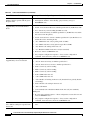
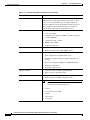
Table 1 provides an overview of the organization of this guide.
Table 1
Cisco ATA 186 and Cisco ATA 188 Analog Telephone Adaptor Administrator’s Guide (H.323) Organization
Chapter
Description
Chapter 1, “Cisco Analog Telephone Adaptor Overview”
Provides descriptions of hardware and software features of
the Cisco ATA Analog Telephone Adaptor along with a brief
overview of the H.323 protocol.
Chapter 2, “Installing the Cisco ATA”
Provides information about installing the Cisco ATA.
Chapter 3, “Configuring the Cisco ATA for H.323”
Provides information about configuring the Cisco ATA and
the various methods for configuration.
Chapter 4, “Basic and Additional H.323 Services”
Provides information about H.323 services that the
Cisco ATA supports.
Chapter 5, “Parameters and Defaults”
Provides information on all parameters and defaults that you
can use to configure the Cisco ATA.
Chapter 6, “Call Commands”
Provides the Cisco ATA call commands for H.323.
Chapter 7, “Configuring and Debugging Fax Services”
Provides instructions for configuring both ports of the
Cisco ATA to support fax transmission.
Chapter 8, “Upgrading the Cisco ATA Signaling Image”
Provides instructions for remotely upgrading Cisco ATA
software.
Chapter 9, “Troubleshooting”
Provides basic testing and troubleshooting procedures for the
Cisco ATA.
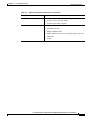
Appendix A, “Using H.323 Supplementary Services”
Provides end-user information about pre-call and mid-call
services.
Appendix B, “Voice Menu Codes”
Provides a quick-reference list of the voice configuration
menu options for the Cisco ATA.
Appendix C, “Cisco ATA Specifications”
Provides physical specifications for the Cisco ATA.
Appendix D, “H.323 Signaling”
Provides Cisco ATA call flows for H.323 scenarios.
Glossary
Provides definitions of commonly used terms.
Index
Provides reference information.
Conventions
This document uses the following conventions:
•
Alternative keywords are grouped in braces and separated by vertical bars (for example, {x | y | z}).
•
Arguments for which you supply values are in italic font.
•
Commands and keywords are in boldface font.
•
Elements in square brackets ([ ]) are optional.
•
Information you must enter is in boldface
•
Optional alternative keywords are grouped in brackets and separated by vertical bars (for example,
[x | y | z]).
screen
font.
Cisco ATA 186 and Cisco ATA 188 Analog Telephone Adaptor Administrator’s Guide (H.323)
xii
OL-4008-01
Preface
Conventions
•
Note
Timesaver
Tip
Caution
Terminal sessions and information the system displays are in screen font.
Means reader take note. Notes contain helpful suggestions or references to material not covered in the
publication.
Means the described action saves time. You can save time by performing the action described in the
paragraph.
Means the following information will help you solve a problem. The tips information might not be
troubleshooting or even an action, but could be useful information, similar to a Timesaver.
Means reader be careful. In this situation, you might do something that could result in equipment
damage or loss of data.
Warning
This warning symbol means danger. You are in a situation that could cause bodily injury. Before you
work on any equipment, be aware of the hazards involved with electrical circuitry and be familiar
with standard practices for preventing accidents. (To see translations of the warnings that appear
in this publication, refer to the appendix “Translated Safety Warnings.”)
Waarschuwing
Dit waarschuwingssymbool betekent gevaar. U verkeert in een situatie die lichamelijk letsel kan
veroorzaken. Voordat u aan enige apparatuur gaat werken, dient u zich bewust te zijn van de bij
elektrische schakelingen betrokken risico’s en dient u op de hoogte te zijn van standaard
maatregelen om ongelukken te voorkomen. (Voor vertalingen van de waarschuwingen die in deze
publicatie verschijnen, kunt u het aanhangsel “Translated Safety Warnings” (Vertalingen van
veiligheidsvoorschriften) raadplegen.)
Varoitus
Tämä varoitusmerkki merkitsee vaaraa. Olet tilanteessa, joka voi johtaa ruumiinvammaan. Ennen
kuin työskentelet minkään laitteiston parissa, ota selvää sähkökytkentöihin liittyvistä vaaroista ja
tavanomaisista onnettomuuksien ehkäisykeinoista. (Tässä julkaisussa esiintyvien varoitusten
käännökset löydät liitteestä "Translated Safety Warnings" (käännetyt turvallisuutta koskevat
varoitukset).)
Attention
Ce symbole d’avertissement indique un danger. Vous vous trouvez dans une situation pouvant
entraîner des blessures. Avant d’accéder à cet équipement, soyez conscient des dangers posés par
les circuits électriques et familiarisez-vous avec les procédures courantes de prévention des
accidents. Pour obtenir les traductions des mises en garde figurant dans cette publication, veuillez
consulter l’annexe intitulée « Translated Safety Warnings » (Traduction des avis de sécurité).
Cisco ATA 186 and Cisco ATA 188 Analog Telephone Adaptor Administrator’s Guide (H.323)
OL-4008-01
xiii
Preface
Related Documentation
Warnung
Dieses Warnsymbol bedeutet Gefahr. Sie befinden sich in einer Situation, die zu einer
Körperverletzung führen könnte. Bevor Sie mit der Arbeit an irgendeinem Gerät beginnen, seien Sie
sich der mit elektrischen Stromkreisen verbundenen Gefahren und der Standardpraktiken zur
Vermeidung von Unfällen bewußt. (Übersetzungen der in dieser Veröffentlichung enthaltenen
Warnhinweise finden Sie im Anhang mit dem Titel “Translated Safety Warnings” (Übersetzung der
Warnhinweise).)
Avvertenza
Questo simbolo di avvertenza indica un pericolo. Si è in una situazione che può causare infortuni.
Prima di lavorare su qualsiasi apparecchiatura, occorre conoscere i pericoli relativi ai circuiti
elettrici ed essere al corrente delle pratiche standard per la prevenzione di incidenti. La traduzione
delle avvertenze riportate in questa pubblicazione si trova nell’appendice, “Translated Safety
Warnings” (Traduzione delle avvertenze di sicurezza).
Advarsel
Dette varselsymbolet betyr fare. Du befinner deg i en situasjon som kan føre til personskade. Før du
utfører arbeid på utstyr, må du være oppmerksom på de faremomentene som elektriske kretser
innebærer, samt gjøre deg kjent med vanlig praksis når det gjelder å unngå ulykker. (Hvis du vil se
oversettelser av de advarslene som finnes i denne publikasjonen, kan du se i vedlegget "Translated
Safety Warnings" [Oversatte sikkerhetsadvarsler].)
Aviso
Este símbolo de aviso indica perigo. Encontra-se numa situação que lhe poderá causar danos
fisicos. Antes de começar a trabalhar com qualquer equipamento, familiarize-se com os perigos
relacionados com circuitos eléctricos, e com quaisquer práticas comuns que possam prevenir
possíveis acidentes. (Para ver as traduções dos avisos que constam desta publicação, consulte o
apêndice “Translated Safety Warnings” - “Traduções dos Avisos de Segurança”).
¡Advertencia!
Este símbolo de aviso significa peligro. Existe riesgo para su integridad física. Antes de manipular
cualquier equipo, considerar los riesgos que entraña la corriente eléctrica y familiarizarse con los
procedimientos estándar de prevención de accidentes. (Para ver traducciones de las advertencias
que aparecen en esta publicación, consultar el apéndice titulado “Translated Safety Warnings.”)
Varning!
Denna varningssymbol signalerar fara. Du befinner dig i en situation som kan leda till personskada.
Innan du utför arbete på någon utrustning måste du vara medveten om farorna med elkretsar och
känna till vanligt förfarande för att förebygga skador. (Se förklaringar av de varningar som
förekommer i denna publikation i appendix "Translated Safety Warnings" [Översatta
säkerhetsvarningar].)
Related Documentation
•
RFC971 (A Survey of Data Representation Standards)
•
RFC768 (User Datagram Protocol)
•
RFC2198 (RTP Payload for Redundant Audio Data)
•
RFC2833 (RTP Payload for DTMF Digits, Telephony Phones and Telephony Signals)
•
Read Me First - ATA Boot Load Information
•
Cisco ATA 186 and Cisco 188 Analog Telephone Adaptor At a Glance
•
Regulatory Compliance and Safety Information for the Cisco ATA 186 and Cisco 188
•
Cisco ATA Release Notes
Cisco ATA 186 and Cisco ATA 188 Analog Telephone Adaptor Administrator’s Guide (H.323)
xiv
OL-4008-01
Preface
Obtaining Documentation
Obtaining Documentation
These sections explain how to obtain documentation from Cisco Systems.
World Wide Web
You can access the most current Cisco documentation on the World Wide Web at this URL:
http://www.cisco.com
Translated documentation is available at this URL:
http://www.cisco.com/public/countries_languages.shtml
Documentation CD-ROM
Cisco documentation and additional literature are available in a Cisco Documentation CD-ROM
package, which is shipped with your product. The Documentation CD-ROM is updated monthly and may
be more current than printed documentation. The CD-ROM package is available as a single unit or
through an annual subscription.
Ordering Documentation
You can order Cisco documentation in these ways:
•
Registered Cisco.com users (Cisco direct customers) can order Cisco product documentation from
the Networking Products MarketPlace:
http://www.cisco.com/cgi-bin/order/order_root.pl
•
Registered Cisco.com users can order the Documentation CD-ROM through the online Subscription
Store:
http://www.cisco.com/go/subscription
•
Nonregistered Cisco.com users can order documentation through a local account representative by
calling Cisco Systems Corporate Headquarters (California, U.S.A.) at 408 526-7208 or, elsewhere
in North America, by calling 800 553-NETS (6387).
Documentation Feedback
You can submit comments electronically on Cisco.com. In the Cisco Documentation home page, click
the Fax or Email option in the “Leave Feedback” section at the bottom of the page.
You can e-mail your comments to [email protected].
You can submit your comments by mail by using the response card behind the front cover of your
document or by writing to the following address:
Cisco Systems
Attn: Document Resource Connection
170 West Tasman Drive
San Jose, CA 95134-9883
Cisco ATA 186 and Cisco ATA 188 Analog Telephone Adaptor Administrator’s Guide (H.323)
OL-4008-01
xv
Preface
Obtaining Technical Assistance
We appreciate your comments.
Obtaining Technical Assistance
Cisco provides Cisco.com as a starting point for all technical assistance. Customers and partners can
obtain online documentation, troubleshooting tips, and sample configurations from online tools by using
the Cisco Technical Assistance Center (TAC) Web Site. Cisco.com registered users have complete access
to the technical support resources on the Cisco TAC Web Site.
Cisco.com
Cisco.com is the foundation of a suite of interactive, networked services that provides immediate, open
access to Cisco information, networking solutions, services, programs, and resources at any time, from
anywhere in the world.
Cisco.com is a highly integrated Internet application and a powerful, easy-to-use tool that provides a
broad range of features and services to help you with these tasks:
•
Streamline business processes and improve productivity
•
Resolve technical issues with online support
•
Download and test software packages
•
Order Cisco learning materials and merchandise
•
Register for online skill assessment, training, and certification programs
If you want to obtain customized information and service, you can self-register on Cisco.com. To access
Cisco.com, go to this URL:
http://www.cisco.com
Technical Assistance Center
The Cisco Technical Assistance Center (TAC) is available to all customers who need technical assistance
with a Cisco product, technology, or solution. Two levels of support are available: the Cisco TAC
Web Site and the Cisco TAC Escalation Center.
Cisco TAC inquiries are categorized according to the urgency of the issue:
•
Priority level 4 (P4)—You need information or assistance concerning Cisco product capabilities,
product installation, or basic product configuration.
•
Priority level 3 (P3)—Your network performance is degraded. Network functionality is noticeably
impaired, but most business operations continue.
•
Priority level 2 (P2)—Your production network is severely degraded, affecting significant aspects
of business operations. No workaround is available.
•
Priority level 1 (P1)—Your production network is down, and a critical impact to business operations
will occur if service is not restored quickly. No workaround is available.
The Cisco TAC resource that you choose is based on the priority of the problem and the conditions of
service contracts, when applicable.
Cisco ATA 186 and Cisco ATA 188 Analog Telephone Adaptor Administrator’s Guide (H.323)
xvi
OL-4008-01
Preface
Obtaining Technical Assistance
Cisco TAC Web Site
You can use the Cisco TAC Web Site to resolve P3 and P4 issues yourself, saving both cost and time.
The site provides around-the-clock access to online tools, knowledge bases, and software. To access the
Cisco TAC Web Site, go to this URL:
http://www.cisco.com/tac
All customers, partners, and resellers who have a valid Cisco service contract have complete access to
the technical support resources on the Cisco TAC Web Site. The Cisco TAC Web Site requires a
Cisco.com login ID and password. If you have a valid service contract but do not have a login ID or
password, go to this URL to register:
http://www.cisco.com/register/
If you are a Cisco.com registered user, and you cannot resolve your technical issues by using the Cisco
TAC Web Site, you can open a case online by using the TAC Case Open tool at this URL:
http://www.cisco.com/tac/caseopen
If you have Internet access, we recommend that you open P3 and P4 cases through the Cisco TAC
Web Site.
Cisco TAC Escalation Center
The Cisco TAC Escalation Center addresses priority level 1 or priority level 2 issues. These
classifications are assigned when severe network degradation significantly impacts business operations.
When you contact the TAC Escalation Center with a P1 or P2 problem, a Cisco TAC engineer
automatically opens a case.
To obtain a directory of toll-free Cisco TAC telephone numbers for your country, go to this URL:
http://www.cisco.com/warp/public/687/Directory/DirTAC.shtml
Before calling, please check with your network operations center to determine the level of Cisco support
services to which your company is entitled: for example, SMARTnet, SMARTnet Onsite, or Network
Supported Accounts (NSA). When you call the center, please have available your service agreement
number and your product serial number.
Cisco ATA 186 and Cisco ATA 188 Analog Telephone Adaptor Administrator’s Guide (H.323)
OL-4008-01
xvii
Preface
Obtaining Technical Assistance
Cisco ATA 186 and Cisco ATA 188 Analog Telephone Adaptor Administrator’s Guide (H.323)
xviii
OL-4008-01
C H A P T E R
1
Cisco Analog Telephone Adaptor Overview
This section describes the hardware and software features of the Cisco Analog Telephone Adaptor
(Cisco ATA) and includes a brief overview of the H.323 protocol.
The Cisco ATA analog telephone adaptors are handset-to-Ethernet adaptors that allow regular analog
telephones to operate on IP-based telephony networks. Cisco ATAs support two voice ports, each with
an independent telephone number. The Cisco ATA 188 also has an RJ-45 10/100 BASE-T data port.
This section covers the following topics:
•
H.323 Overview, page 1-2
•
Hardware Overview, page 1-5
•
Software Features, page 1-7
•
Installation and Configuration Overview, page 1-9
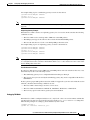
Figure 1-1
Cisco ATA Analog Telephone Adaptor
CISCO A
TA 186
TELEPH
ONE AD
APTOR
72209
ANALOG
The Cisco ATA, which operates with Cisco voice-packet gateways, makes use of broadband pipes that
are deployed through a digital subscriber line (DSL), fixed wireless-cable modem, and other Ethernet
connections.
Note
The term Cisco ATA refers to both the Cisco ATA 186 and the Cisco ATA 188, unless otherwise stated.
Cisco ATA 186 and Cisco ATA 188 Analog Telephone Adaptor Administrator’s Guide (H.323)
OL-4008-01
1-1
Chapter 1
Cisco Analog Telephone Adaptor Overview
H.323 Overview
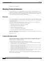
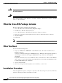
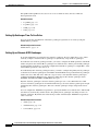
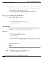
Cisco ATA 186 as Endpoint in an H.323 Network
Voice
gateway
Layer 3
Telephone/fax
Broadband
Ethernet
Cisco ATA 186
Broadband CPE
(DSL, cable,
fixed wireless)
V
IP infrastructure
V
PSTN
72853
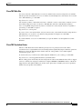
Figure 1-2
H.323 Gatekeeper
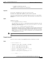
Cisco ATA 188 as Endpoint in an H.323 Network
Voice
gateway
Layer 3
Telephone/fax
Broadband
Ethernet
Cisco ATA 188
Broadband CPE
(DSL, cable,
fixed wireless)
V
IP infrastructure
V
PSTN
72854
Figure 1-3
H.323 Gatekeeper
H.323 Overview
H.323 is the International Telecommunication Union (ITU) standard for transmitting voice, video, and
data across an IP network. Like other VoIP protocols, the H.323 standard is designed to address the
functions of signaling and session management from within a packet telephony network. Signaling
allows call information to be carried across network boundaries. Session management provides the
ability to control the attributes of an end-to-end call. The H.323 standard includes support for call
signaling and control, multimedia transport and control, and bandwidth control for both point-to-point
and point-to-multipoint conferences.
The H.323 standard includes the following protocols:
•
Call signaling using the H.225 protocol
•
Media control using the H.245 protocol
•
G.711, G.722, G.723, G.728, and G.729 audio codecs
•
H.261 and H.263 video codecs
•
Data sharing using the T.120 protocol
•
Real-time transport protocol (RTP) and RTP Control Protocol (RTCP) for media transport
Cisco ATA 186 and Cisco ATA 188 Analog Telephone Adaptor Administrator’s Guide (H.323)
1-2
OL-4008-01
Chapter 1
Cisco Analog Telephone Adaptor Overview
H.323 Overview
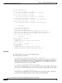
Components that the H.323 standard employs include a system of interconnected voice terminals,
gateways, gatekeepers, multipoint control units (MCUs), and proxy servers. Voice terminals provide
point-to-point and point-to-multipoint conference capability for audio, video, and data. Voice gateways
interconnect the packetized IP network to the PSTN or ISDN network. Gatekeepers provide admission
control and address translation services for H.323 voice terminals and gateways. MCUs enable two or
more gateways to engage in point-to-point or point-to-multipoint audio or video conferences.
This section contains descriptions of the following H.323 components:
•
H.323 Terminals, page 1-3
•
H.323 Gateways, page 1-3
•
H.323 Gatekeepers, page 1-4
•
H.323 MCUs, page 1-4
•
H.323 Proxy Server, page 1-4
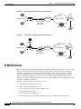
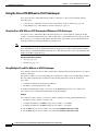
Figure 1-4
H.323 Architecture
Multipoint Control
Unit (MCU)
H.323 Gatekeeper
Analog Phone
H.323 Gateway
H.323
Network
CSN/PSTN
72858
Terminal
Analog Phone
Terminal
Cisco ATA
H.323 Terminals
Voice terminals in an H.323 network must feature system control units, media transmission capabilities,
audio codecs, and network interfaces suitable for transmitting and receiving packetized data.
H.323 Gateways
H.323 gateways feature a mixture of characteristics of both standard Switched Circuit Network (SCN)
access points and H.323 access points. Gateways perform the translation of audio, video, and data
transmission formats as well as interacting with communications systems and various protocols. A
primary responsibility of an H.323 gateway is the call setup and teardown necessary to complete a call
to and from a packetized IP network and a standard switched network.
Note
Gateways are necessary in an H.323 system to connect calls over a packetized IP network to a switched
circuit network such as the PSTN.
Cisco ATA 186 and Cisco ATA 188 Analog Telephone Adaptor Administrator’s Guide (H.323)
OL-4008-01
1-3
Chapter 1
Cisco Analog Telephone Adaptor Overview
H.323 Overview
H.323 Gatekeepers
Gatekeepers are primarily responsible for pre-call and call-level control services for H.323 gateways.
Gatekeepers are an optional component in an H.323 system. However, if present, gatekeepers must
perform the following call setup and management services:
•
Address translation for IP addresses originating from H.323 aliases (for example,
[email protected], for example) or E.164 addresses (for example, standard telephone
numbers)
•
Admissions control for authorizing or rejecting access to H.323
•
Bandwidth control for gateway bandwidth requirements
•
Zone management for registered voice terminals, gateways and MCUs
When used in an H.323 system, gatekeepers can also (but are not required to) provide the following
functionality:
•
Call control signaling using the gatekeeper Routed Call Signaling model
•
Call authorization to restrict access to certain voice terminals or gateways, or to restrict access based
on time-of-day criteria
•
Bandwidth management for the H.323 system that will enable the gateway to restrict access when
requested bandwidth is unavailable
•
Call management including maintaining a list of active calls to indicate available and unavailable
voice terminals and gateways
H.323 MCUs
MCUs are endpoints in an H.323 network that support point-to-multipoint conferences and consist of a
multipoint controller and at least one multipoint processor responsible for receiving voice, video, and
data streams. These streams are distributed to access points participating in a point-to-multipoint
conference.
H.323 Proxy Server
An H.323 proxy server is a proxy specifically designed for the H.323 protocol and examines packets
between two communicating applications. Proxies can determine the destination of a call and perform
call-connection steps, if necessary.
H.323 proxies perform the following key functions:
•
Allow voice terminals that do not support Resource Reservation Protocol (RSVP) to connect to the
proxy through remote access or local area networks with relatively reliable quality of service (QoS).
Pairs of proxies can then be employed to develop tunnels across the IP network.
•
Support routing of H.323 traffic that is separate from ordinary data traffic by using
application-specific routing (ASR).
•
Enable H.323 to be deployed in networks that use private address space.
•
Ensure network security by configuring the proxy server to allow only H.323 traffic over the
network.
Cisco ATA 186 and Cisco ATA 188 Analog Telephone Adaptor Administrator’s Guide (H.323)
1-4
OL-4008-01
Chapter 1
Cisco Analog Telephone Adaptor Overview
Hardware Overview
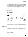
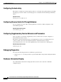
Hardware Overview
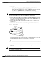
The Cisco ATA 186 and Cisco ATA 188 are compact, easy-to-install devices. Figure 1-5 shows the rear
panel of the Cisco ATA 186. Figure 1-6 shows the rear panel of the Cisco ATA 188.
PHONE 2
10BaseT
ACT
PHONE 1
5V
Power
connector
RJ-11 FXS ports
RJ-45 10BaseT
Figure 1-6
72210
PHONE 1
Cisco ATA 186—Rear View
ACT LED
Cisco ATA 188—Rear View
PHONE 2
LINK
RJ-11 FXS ports
10/100 PC
10/100 UPLINK LINK
72211
Figure 1-5
5V
Power
connector
LINK LED
LINK LED
RJ-45 10/100BaseT ports
The unit provides the following connectors and indicators:
Note
•
5V power connector.
•
Two RJ-11 FXS (Foreign Exchange Station) ports—The Cisco ATA supports two independent RJ-11
telephone ports that can connect to any standard analog telephone device. Each port supports either
voice calls or fax sessions, and both ports can be used simultaneously.
The Cisco ATA186-I1 and Cisco ATA188-I1 provide 600-ohm resistive impedance. The Cisco
ATA186-I2 and Cisco ATA188-I2 provide 270 ohm + 750 ohm // 150-nF complex impedance. The
impedance option is requested when you place your order and should match your specific application.
If you are not sure of the applicable configuration, check your country or regionaltelephone impedance
requirements.
Cisco ATA 186 and Cisco ATA 188 Analog Telephone Adaptor Administrator’s Guide (H.323)
OL-4008-01
1-5
Chapter 1
Cisco Analog Telephone Adaptor Overview
Hardware Overview
•
Ethernet ports
– The Cisco ATA 186 has one RJ-45 10BASE-T uplink Ethernet port to connect the
Cisco ATA 186 to a 10/100BASE-T hub or another Ethernet device.
– The Cisco ATA 188 has two Ethernet ports: an RJ-45 10/100BASE-T uplink port to connect the
Cisco ATA 188 to a 10/100BASE-T hub or another Ethernet device and an RJ-45
10/100BASE-T data port to connect an Ethernet-capable device, such as a computer, to the
network.
Note
The Cisco ATA 188 performs auto-negotiation for duplexity and speed and is capable of 10/100 Mbps,
full-duplex operation. The Cisco ATA 186 is fixed at 10 Mbps, half-duplex operation.
•
The Cisco ATA 188 RJ-45 LED shows network link and activity. The LED blinks twice when the
Cisco ATA is first powered on, then turns off if there is no link or activity. The LED blinks to show
network activity and is solid when there is a link.
•
The Cisco ATA 186 RJ-45 LED is solid when the Cisco ATA is powered on and blinks to show
network activity.
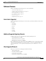
•
Function button—The function button is located on the top panel of the unit (see Figure 1-7).
Figure 1-7
Function Button
Function
button
CISCO
72214
ATA 186
ANALOG
TELEPH
ONE AD
APTOR
The function button lights when you pick up the handset of a telephone attached to the Cisco ATA.
The button blinks quickly when the Cisco ATA is upgrading its configuration.
Note
If the function button blinks slowly, the Cisco ATA cannot find the DHCP server. Check your
Ethernet connections and make sure the DHCP server is available.
Pressing the function button allows you to access to the voice configuration menu. For additional
information about the voice configuration menu, see the “Voice Configuration Menu” section on
page 3-15.
Caution
Never press the function button during an upgrade process. Doing so may interfere with the process and
may permanently disable the Cisco ATA.
Cisco ATA 186 and Cisco ATA 188 Analog Telephone Adaptor Administrator’s Guide (H.323)
1-6
OL-4008-01
Chapter 1
Cisco Analog Telephone Adaptor Overview
Software Features
Software Features
The Cisco ATA supports the following protocols, services and methods:
•
Voice Codecs Supported, page 1-7
•
Additional Supported Signaling Protocols, page 1-7
•
Other Supported Protocols, page 1-7
•
Cisco ATA H.323 Services, page 1-8
•
Fax Services, page 1-9
•
Supplementary Services, page 1-9
Voice Codecs Supported
The Cisco ATA supports the following voice codecs (check your other network devices for the codecs
they support):
•
G.711µ-law
•
G.711A-law
•
G.723.1
•
G.729
•
G.729A
•
G.729B
•
G.729AB
Additional Supported Signaling Protocols
In addition to H.323, the Cisco ATA supports the following signaling protocols:
•
Session Initiation Protocol (SIP)
•
Skinny Client Control Protocol (SCCP)
•
Media Gateway Control Protocol (MGCP)
H.323 and SIP share the same software image. SCCP and MGCP also share a software image, which is
separate from the H.323/SIP image. If you wish to perform a cross-protocol upgrade from H.323 to
another signaling image, see the “Upgrading the Signaling Image from a TFTP Server” section on
page 8-1.
Other Supported Protocols
Other protocols that the Cisco ATA supports include the following:
•
802.1Q VLAN tagging
•
Cisco Discovery Protocol (CDP)
•
Domain Name System (DNS)
•
Dynamic Host Configuration Protocol (DHCP)
Cisco ATA 186 and Cisco ATA 188 Analog Telephone Adaptor Administrator’s Guide (H.323)
OL-4008-01
1-7
Chapter 1
Cisco Analog Telephone Adaptor Overview
Software Features
•
Internet Control Message Protocol (ICMP)
•
Internet Protocol (IP)
•
Real-Time Transport Protocol (RTP)
•
Transmission Control Protocol (TCP)
•
Trivial File Transfer Protocol (TFTP)
•
User Datagram Protocol (UDP)
Cisco ATA H.323 Services
For a list of required H.323 parameters as well as descriptions of all supported Cisco ATA H.323 services
and cross references to the parameters for configuring these services, see Chapter 4, “Basic and
Additional H.323 Services.”
These services include the following features:
•
Supports direct IP dialing to and from a Cisco ATA without using an H.323 gatekeeper
•
Supports direct IP dialing in addition to proxy-routed calls to and from either phone
•
Uses the same configurable MediaPort to transmit and receive RTP audio
•
Uses UDP only for H.323 RAS message transmission
•
Uses a TCP connection for H.225/Q.931 signaling (such as call setup, call proceeding, alerting, and
call connect)
•
IP address assignment—DHCP-provided or statically configured
•
Cisco ATA configuration by means of a TFTP server, web browser, or voice configuration menu.
•
VLAN configuration
•
Cisco Discovery Protocol (CDP)
•
Low-bit-rate codec selection
•
User authentication
•
Configurable tones (dial tone, busy tone, alert tone, reorder tone, call waiting tone)
•
Dial plans
•
User-configurable, call-waiting, permanent default setting
•
Silence suppression and comfort noise generation for G.711, G.723.1 (G.723.1 Annex A), and
G.,729 (G.729 Annex B)
•
Caller ID format
•
Ring cadence format
•
Hook-flash detection timing configuration
•
UDP Type of Service (ToS) configuration
•
Hotline and warmline support (private line automatic ringdown)
•
Debugging and diagnostic tools
Cisco ATA 186 and Cisco ATA 188 Analog Telephone Adaptor Administrator’s Guide (H.323)
1-8
OL-4008-01
Chapter 1
Cisco Analog Telephone Adaptor Overview
Installation and Configuration Overview
Fax Services
The Cisco ATA supports two modes of fax services, in which fax signals are transmitted using the G.711
codec:
•
Fax pass-through mode—Receiver-side Called Station Identification (CED) tone detection with
automatic G.711A-law or G.711µ-law switching.
•
Fax mode—The Cisco ATA is configured as a G.711-only device.
How you set Cisco ATA fax parameters depends on what network gateways are being used. You may
need to modify the default fax parameter values (see Chapter 7, “Configuring and Debugging Fax
Services”).
Note
Success of fax transmission depends on network conditions and fax modem response to these conditions.
The network must have reasonably low network jitter, network delay, and packet loss rate.
Supplementary Services
H.323 supplementary services are services that you can use to enhance your telephone service. For
information on how to enable and subscribe to these services, see the “CallFeatures” section on
page 5-24 and the “PaidFeatures” section on page 5-25.
For information on how to use these services, see Appendix A, “Using H.323 Supplementary Services.”
The following list contains the H.323 supplementary services that the Cisco ATA supports:
•
Caller ID
•
Calling line ID presentation/rejection (CLIP/CLIR)
•
Call waiting
•
Call waiting Caller ID
•
Three-way calling
Installation and Configuration Overview
Table 1-1 provides the basic steps required to install and configure the Cisco ATA to make it operational.
Table 1-1
Overview of the Steps Required to Install and Configure the Cisco ATA and Make it Operational
Action
Reference
1.
Plan the network and Cisco ATA configuration.
2.
Install the Ethernet connection.
3.
Install and configure the other network devices.
4.
Install the Cisco ATA but do not power up the Cisco ATA yet.
5.
Download the desired Cisco ATA release software zip file from Chapter 3, “Configuring the Cisco ATA for H.323”
the Cisco web site, then configure the Cisco ATA.
What the Cisco ATA Package Includes, page 2-2
Cisco ATA 186 and Cisco ATA 188 Analog Telephone Adaptor Administrator’s Guide (H.323)
OL-4008-01
1-9
Chapter 1
Cisco Analog Telephone Adaptor Overview
Installation and Configuration Overview
Action
Reference
6.
Power up the Cisco ATA.
7.
Periodically, you can upgrade the Cisco ATA to a new signaling Chapter 8, “Upgrading the Cisco ATA Signaling
image by using the TFTP server-upgrade method or the
Image”
manual-upgrade method.
Cisco ATA 186 and Cisco ATA 188 Analog Telephone Adaptor Administrator’s Guide (H.323)
1-10
OL-4008-01
C H A P T E R
2
Installing the Cisco ATA
This section provides instructions for installing the Cisco ATA 186 and Cisco ATA 188. Before you
perform the installation, be sure you have met the following prerequisites:
•
Planned the network and Cisco ATA configuration.
•
Installed the Ethernet connection.
•
Installed and configured the other network devices.
This section contains the following topics:
Note
•
Safety Recommendations, page 2-1
•
What the Cisco ATA Package Includes, page 2-2
•
What You Need, page 2-2
•
Installation Procedure, page 2-2
•
Power-Down Procedure, page 2-5
The term Cisco ATA is used throughout this manual to refer to both the Cisco ATA 186 and the
Cisco ATA 188, unless differences between the Cisco ATA 186 and Cisco ATA 188 are explicitly stated.
Safety Recommendations
To ensure general safety, follow these guidelines:
•
Do not get this product wet or pour liquids into this device.
•
Do not open or disassemble this product.
•
Do not perform any action that creates a potential hazard to people or makes the equipment unsafe.
•
Use only the power cube that comes with the Cisco ATA.
Warning
Ultimate disposal of this product should be handled according to all national laws and regulations.
Warning
Read the installation instructions before you connect the system to its power source.
Cisco ATA 186 and Cisco ATA 188 Analog Telephone Adaptor Administrator’s Guide (H.323)
OL-4008-01
2-1
Chapter 2
Installing the Cisco ATA
What the Cisco ATA Package Includes
Warning
The plug-socket combination must be accessible at all times because it serves as the main
disconnecting device.
Warning
Do not work on the system or connect or disconnect cables during periods of lightning activity.
For translated warnings, see the Regulatory Compliance and Safety Information for the Cisco ATA 186
and Cisco ATA 188 manual.
What the Cisco ATA Package Includes
The Cisco ATA package contains the following items:
•
Cisco ATA 186 or Cisco ATA 188 Analog Telephone Adaptor
•
Read Me First - ATA Boot Load Information
•
Cisco ATA 186 and Cisco ATA 188 Analog Telephone Adaptor at a Glance
•
Regulatory Compliance and Safety Information for the Cisco ATA 186 and Cisco ATA 188
•
5V power adaptor
•
Power cord
Note
The Cisco ATA is intended for use only with the 5V DC power adaptor that comes with the unit.
What You Need
You also need the following items:
•
Category-3 10BASE-T or 100BASE-T or better Ethernet cable. One cable is needed for each
Ethernet connection.
A Category-3 Ethernet cable supports 10BASE-T for up to 100 meters without quality degradation,
and a Category-3 Ethernet cable supports 100BASE-T for up to 10 meters without quality
degradation.
For uplink connections, use a crossover Ethernet cable to connect the Cisco ATA to another Ethernet
device (such as a router or PC) without using a hub. Otherwise, use straight-through Ethernet cables
for both uplink and data port connections.
•
Access to an IP network
•
One or two analog Touch-Tone telephones or fax machines, or one of each
Installation Procedure
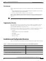
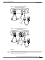
After the equipment is in place, see Figure 2-1 (for Cisco ATA 186) or Figure 2-2 (for Cisco ATA 188)
and follow the next procedure to install the Cisco ATA.
Cisco ATA 186 and Cisco ATA 188 Analog Telephone Adaptor Administrator’s Guide (H.323)
2-2
OL-4008-01
Chapter 2
Installing the Cisco ATA
Installation Procedure
PHONE 1
Cisco ATA 186 Rear Panel Connections
PHONE 2
10BaseT
ACT
72212
Figure 2-1
5V
Power outlet
IP network
Analog telephones
(or fax)
5V power
adaptor
Power cord
PHONE 1
Cisco ATA 188 Rear Panel Connections
PHONE 2
LINK
10/100 PC
10/100 UPLINK LINK
72213
Figure 2-2
5V
Power outlet
IP network
Analog telephones
(or fax)
PC
5V power
adaptor
Power cord
Procedure
Step 1
Place the Cisco ATA near an electrical power outlet.
Step 2
Connect one end of a telephone line cord to the Phone 1 input on the rear panel of the Cisco ATA.
Connect the other end to an analog telephone set.
Cisco ATA 186 and Cisco ATA 188 Analog Telephone Adaptor Administrator’s Guide (H.323)
OL-4008-01
2-3
Chapter 2
Installing the Cisco ATA
Installation Procedure
If you are connecting a telephone set that was previously connected to an active telephone line, unplug
the telephone line cord from the wall jack and plug it into the Phone 1 input.
Warning
Caution
Note
Step 3
To reduce the risk of fire, use only No. 26 AWG or larger telecommunication line cord.
Do not connect the Phone input ports to a telephone wall jack. To avoid damaging the Cisco ATA or
telephone wiring in the building, do not connect the Cisco ATA to the telecommunications network.
Connect the Phone port to a telephone only, never to a telephone wall jack.
The telephone must be switched to tone setting (not pulse) for the Cisco ATA to operate properly.
(Optional) Connect the telephone line cord of a second telephone to the Phone 2 input port.
If you are connecting only one telephone to the Cisco ATA, you must use the Phone 1 input port.
Step 4
Connect an Ethernet cable to the uplink RJ-45 connector on the Cisco ATA. For the Cisco ATA 186,
this is the 10BASE-T connector; for the Cisco ATA 188, this is the 10/100UPLINK connector.
Use a crossover Ethernet cable to connect the Cisco ATA to another Ethernet device (such as a router or
PC) without using a hub. Otherwise, use a straight-through Ethernet cable.
Step 5
(Cisco ATA 188 only—optional) Connect a straight-through Ethernet cable from your PC to the 10/100
PC RJ-45 connector on the Cisco ATA.
Step 6
Connect the socket end of the power cord to the 5V DC power adaptor.
Step 7
Insert the power adaptor cable into the power connector on the Cisco ATA.
Warning
Step 8
This product relies on the building’s installation for short-circuit (overcurrent) protection. Ensure that
a fuse or circuit breaker no larger than 120 VAC, 15A U.S. (240VAC, 10A international) is used on the
phase conductors (all current-carrying conductors).
Connect the plug end of the 5V DC power adaptor cord into an electrical power outlet.
When the Cisco ATA is properly connected and powered up, the green activity LED flashes to indicate
network activity. This LED is labeled ACT on the rear panel of the Cisco ATA 186 and is labeled LINK
on the rear panel of the Cisco ATA 188.
Caution
Do not cover or block the air vents on either the top or the bottom surface of the Cisco ATA. Overheating
can cause permanent damage to the unit.
For more information about LEDs and the function button, see the “Hardware Overview” section on
page 1-5.
Cisco ATA 186 and Cisco ATA 188 Analog Telephone Adaptor Administrator’s Guide (H.323)
2-4
OL-4008-01
Chapter 2
Installing the Cisco ATA
Power-Down Procedure
Power-Down Procedure
Caution
If you need to power down Cisco ATA 186 or Cisco 188 at any time, use the following power-down
procedure to prevent damage to the unit.
Procedure
Step 1
Unplug the RJ45 Ethernet cable
Step 2
Wait for 20 seconds.
Step 3
Unplug the power cable.
Cisco ATA 186 and Cisco ATA 188 Analog Telephone Adaptor Administrator’s Guide (H.323)
OL-4008-01
2-5
Chapter 2
Installing the Cisco ATA
Power-Down Procedure
Cisco ATA 186 and Cisco ATA 188 Analog Telephone Adaptor Administrator’s Guide (H.323)
2-6
OL-4008-01
C H A P T E R
3
Configuring the Cisco ATA for H.323
This section describes how to configure the Cisco ATA to operate with the H.323 signaling image and
how the Cisco ATA obtains the latest signaling image.
You can configure the Cisco ATA for use with H.323 with any of the following methods:
•
By using a TFTP server—This is the Cisco-recommended method for deploying a large number of
Cisco ATAs. This method allows you to set up a unique Cisco ATA configuration file or a
configuration file that is common to all Cisco ATAs. The Cisco ATA can automatically download its
latest configuration file from the TFTP server when the Cisco ATA powers up, is refreshed or reset,
or when the specified TFTP query interval expires.
•
By using manual configuration:
– Voice configuration menu—This is the method you must use if the process of establishing IP
connectivity for the Cisco ATA requires changing the default network configuration settings. These
settings are CDP, VLAN, and DHCP. You also can use the voice configuration menu to review all IP
connectivity settings. The voice configuration menu can also be used when Web access is not
available.
– Web-based configuration—This method is convenient if you plan to deploy a small number of
Cisco ATAs in your network. To use this method, the Cisco ATA must first obtain IP connectivity,
either through the use of a DHCP server or by using the voice configuration menu to statically
configure IP addresses.
This section contains the following topics:
•
Default Boot Load Behavior, page 3-2—This section describes the process that the Cisco ATA
follows by default when it boots up. It is very important to understand this process because, if your
network environment is not set up to follow this default behavior, you need to make the applicable
configuration changes. For example, by default, the Cisco ATA attempts to contact a DHCP server
for the necessary IP addresses to achieve network connectivity. However, if your network does not
use a DHCP server, you must manually configure various IP settings as described in this section.
•
Specifying a Preconfigured VLAN ID or Disabling VLAN IP Encapsulation, page 3-3—This section
includes a table of the parameters you can configure for VLAN and CDP settings.
•
Steps Needed to Configure the Cisco ATA, page 3-5—This section provides tables that summarize
the general configuration steps you must follow to configure the Cisco ATA.
•
Configuring the Cisco ATA Using a TFTP Server, page 3-7—This section describes procedures for
configuring the Cisco ATA by using a TFTP server, which is the recommended configuration
method for the deployment of a large number of Cisco ATAs.
•
Voice Configuration Menu, page 3-15—This section includes information on how to obtain basic
network connectivity for the Cisco ATA and how to perform a factory reset if necessary.
Cisco ATA 186 and Cisco ATA 188 Analog Telephone Adaptor Administrator’s Guide (H.323)
OL-4008-01
3-1
Chapter 3
Configuring the Cisco ATA for H.323
Default Boot Load Behavior
Note
•
Cisco ATA Web Configuration Page, page 3-18—This section shows the Cisco ATA Web
configuration page and contains a procedure for how to configure Cisco ATA parameters using this
interface.
•
Web Interface Access-Control Configuration, page 3-20
•
Refreshing or Resetting the Cisco ATA, page 3-20—This section gives the procedure (via the Web
configuration page) for refreshing or resetting the Cisco ATA so that your most recent configuration
changes take effect immediately.
•
Upgrading the H.323 Signaling Image, page 3-21—This section provides references to the various
means of upgrading your Cisco ATA signaling image.
The term Cisco ATA is used throughout this manual to refer to both the Cisco ATA 186 and the
Cisco ATA 188, unless differences between the Cisco ATA 186 and Cisco ATA 188 are explicitly stated.
Default Boot Load Behavior
Before configuring the Cisco ATA, you need to know how the default Cisco ATA boot load process
works. Once you understand this process, you will be able to configure the Cisco ATA by following the
instructions provided in this section and in the sections that follow.
All Cisco ATAs are shipped with a boot load signaling-protocol image. However, because this image is
not a fully functional signaling image, the image must be upgraded. The image is designed to be
automatically upgraded by a properly configured TFTP server. To configure the Cisco ATA to
automatically upgrade to the latest signaling image, see the “Upgrading the Signaling Image from a
TFTP Server” section on page 8-1.
In addition, the Cisco ATA obtains its configuration file during the boot load process.
The following list summarizes the default Cisco ATA behavior during its boot-up process:
1.
Note
2.
Note
3.
The Cisco ATA uses the Cisco Discovery Protocol (CDP) to discover which VLAN to enter. If the
Cisco ATA receives a VLAN ID response from the network switch, the Cisco ATA enters that VLAN
and adds 802.1Q VLAN tags to its IP packets. If the Cisco ATA does not receive a response with a
VLAN ID from the network switch, then the Cisco ATA assumes it is not operating in a VLAN
environment and does not perform VLAN tagging on its packets.
If your network environment is not set up to handle this default behavior, make the necessary
configuration changes by referring to the “Specifying a Preconfigured VLAN ID or Disabling
VLAN IP Encapsulation” section on page 3-3.
The Cisco ATA contacts the DHCP server to request its own IP address.
If your network environment does not contain a DHCP server, you need to statically configure
various IP addresses so that the Cisco ATA can obtain network connectivity. For a list of
parameters that you must configure to obtain network connectivity, see Table 3-5 on page 3-16.
For instructions on how to use the voice configuration menu, which you must use to perform this
configuration, see the “Voice Configuration Menu” section on page 3-15.
Also from the DHCP server, the Cisco ATA requests the IP address of the TFTP server.
Cisco ATA 186 and Cisco ATA 188 Analog Telephone Adaptor Administrator’s Guide (H.323)
3-2
OL-4008-01
Chapter 3
Configuring the Cisco ATA for H.323
Specifying a Preconfigured VLAN ID or Disabling VLAN IP Encapsulation
4.
Note
Note
The Cisco ATA contacts the TFTP server and downloads the Cisco ATA release software that
contains the correct signaling image for the Cisco ATA to function properly.
If you are not using a TFTP server, you need to manually upgrade the Cisco ATA to the correct
signaling image. For information on this procedure, see the “Upgrading the Signaling Image
Manually” section on page 8-2.
5.
The Cisco ATA looks for a Cisco ATA-specific configuration file (designated by the MAC address
of the Cisco ATA and named ata<macaddress>) on the TFTP server and downloads this file if it
exists.
6.
If the Cisco ATA does not find the ata<macaddress> configuration file, it looks for the
atadefault.cfg configuration file and downloads this file if it exists. This file can contain default
values for the Cisco ATA to use.
When the Cisco ATA is downloading its DHCP configuration, the function button on the top panel
blinks.
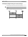
Specifying a Preconfigured VLAN ID or Disabling VLAN IP
Encapsulation
If you want the Cisco ATA to use a preconfigured VLAN ID instead of using the Cisco Discovery
Protocol to locate a VLAN, or if you want to disable VLAN IP encapsulation, refer to Table 3-1 for a
reference to the parameters and bits you may need to configure. Use the voice configuration menu to
configure these parameters. (See the “Voice Configuration Menu” section on page 3-15 for instructions
on using this menu.) Also, refer to Table 3-2 for a matrix on which VLAN-related parameters and bits
to configure depending on your network environment.
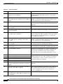
Table 3-1
Parameters and Bits for Preconfiguring a VLAN ID
Parameter and Bits
Reference
OpFlags:
OpFlags, page 5-33
•
Bit 4—Enable the use of user-specified voice VLAN ID.
•
Bit 5—Disable VLAN encapsulation
•
Bit 6—Disable CDP discovery.
VLANSetting:
VLANSetting, page 5-34
•
Bits 0-2—Specify VLAN CoS bit value (802.1P priority) for TCP
packets.
•
Bits 3-5—Specify VLAN CoS bit value (802.1P priority) for UDP
packets
•
Bits 18-29—User-specified 802.1Q VLAN ID
Cisco ATA 186 and Cisco ATA 188 Analog Telephone Adaptor Administrator’s Guide (H.323)
OL-4008-01
3-3
Chapter 3
Configuring the Cisco ATA for H.323
Specifying a Preconfigured VLAN ID or Disabling VLAN IP Encapsulation
Table 3-2
VLAN-Related Features and Corresponding Configuration Parameters
VLANSetting
OpFlags Bit 4 OpFlags Bit 5 OpFlags Bit 6 Bits 18-29
Feature
Static VLAN
1
0
1
VLAN ID
CDP-acquired
VLAN
0
0
0
N/A
No VLAN
N/A
1
N/A
N/A
No CDP
N/A
N/A
1
N/A
No CDP and no
VLAN
0
1
1
N/A
N/A indicates that the variable is not applicable to the feature and the setting of this varaible does not affect the feature.
Example
The following procedure shows you how to configure the OpFlags and VLANSetting parameters to allow
the Cisco ATA to use a user-specified VLAN ID. In this example, the voice VLAN ID is 115 (in decimal
format).
Step 1
Set bits 4-6 of the OpFlags parameter to 1, 0, and 1, respectively. This setting translates to the following
bitmap:
xxxx xxxx xxxx xxxx xxxx xxxx x101 xxxx
The remaining bits of the OpFlags parameter, using all default values, make up the following bitmap
representation:
0000 0000 0000 0000 0000 0000 0xxx 0010
Therefore, the resulting value of the OpFlags parameter becomes the following bitmap representation:
0000 0000 0000 0000 0000 0000 0101 0010
In hexadecimal format, this value is 0x00000052.
Step 2
Set bits 18-29 of the VLANSetting parameter to to voice VLAN ID 115. This setting translates to the
following bitmap
xx00 0001 1100 11xx xxxx xxxx xxxx xxxx
where 000001110011 is the binary representation of the demical value 115.
The remaining bits of the VLANSetting parameter, using all default values, make up the following
representation:
00xx xxxx xxxx xx00 0000 0000 0010 1011
Therefore, the resulting value of the VLANSetting parameter becomes the following bitmap
representation:
0000 0001 1100 1100 0000 0000 0010 1011
In hexadecimal format, this value is 0x01cc002b.
Cisco ATA 186 and Cisco ATA 188 Analog Telephone Adaptor Administrator’s Guide (H.323)
3-4
OL-4008-01
Chapter 3
Configuring the Cisco ATA for H.323
Steps Needed to Configure the Cisco ATA
Note
If you are using the voice configuration menu to set the parameters, you must convert hexadecimal values
to decimal values. For example, the OpFlags setting of 0x00000052 is equivalent to 82 in decimal
format, and the VLANSetting of 0x01cc002b is equivalent to 30146603 in decimal format.
Steps Needed to Configure the Cisco ATA
This section contains the following topics:
•
Basic Configuration Steps in a TFTP Server Environment, page 3-5
•
Basic Configuration Steps in a Non-TFTP Server Environment, page 3-6
Basic Configuration Steps in a TFTP Server Environment
Table 3-3 shows the basic steps for configuring the Cisco ATA and making it operational in a typical
H.323 environment, which includes a TFTP server.
Table 3-3
Basic Steps to Configure the Cisco ATA in a TFTP Environment
Action
Reference
1.
Download the desired Cisco ATA release software zip file from
the Cisco web site and store it on the TFTP server.
Setting Up the TFTP Server with Cisco ATA
Software, page 3-7
2.
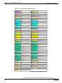
Follow these basic steps to create a unique Cisco ATA
configuration file, which actually entails creating two files:
Creating Unique and Common Cisco ATA
Configuration Files, page 3-8
a. Create a Cisco ATA configuration text file that contains
parameters that are common to all Cisco ATAs in your
network.
b. Create a unique Cisco ATA configuration text file that
contains parameters that are specific to a Cisco ATA.
Make sure to use an include command in the unique
configuration file to pull in values from the common
configuration file.
c. Convert the unique configuration file to binary format.
d. Place the unique binary configuration file on the TFTP server.
atadefault.cfg Configuration File, page 3-12
3.
Optionally, create a default configuration file called
atadefault.cfg, which the Cisco ATA will download from the
TFTP server only if the unique Cisco ATA file called
ata<macaddress> does not exist on the TFTP server.
4.
Configure the upgradecode parameter so that the Cisco ATA will Upgrading the Signaling Image from a TFTP Server,
obtain the correct signaling image from the TFTP server when the page 8-1
Cisco ATA powers up.
5.
Configure the desired interval for the Cisco ATA to contact the
TFTP server to check for a configuration-file update or an
upgrade of the signaling image file.
Setting Up User IDs for the Cisco ATA, page 4-3
Cisco ATA 186 and Cisco ATA 188 Analog Telephone Adaptor Administrator’s Guide (H.323)
OL-4008-01
3-5
Chapter 3
Configuring the Cisco ATA for H.323
Steps Needed to Configure the Cisco ATA
Table 3-3
Basic Steps to Configure the Cisco ATA in a TFTP Environment (continued)
Action
Reference
6.
Configure the method with which the Cisco ATA will locate the
TFTP server at boot up time.
7.
Power up the Cisco ATA.
8.
If you make configuration changes to the Cisco ATA or upgrade
the signaling image on the TFTP server, you can refresh the
Cisco ATA so that these changes take effect immediately.
Otherwise, these changes will take effect when the specified
interval (CfgInterval parameter value) for the TFTP query
expires.
Configuring the Cisco ATA to Obtain its
Configuration File from the TFTP Server, page 3-12
Refreshing or Resetting the Cisco ATA, page 3-20
Basic Configuration Steps in a Non-TFTP Server Environment
Table 3-4 shows the basic steps for configuring the Cisco ATA without using the TFTP server method.
Table 3-4
Basic Steps to Configure the Cisco ATA Without Using the TFTP Server Method
Action
1.
Reference
Download the desired Cisco ATA release software zip file from the Cisco web site:
a. If you are a registered CCO user. go to the following URL:
http://www.cisco.com/cgi-bin/tablebuild.pl/ata186
b. Download the zip file that contains the software for the applicable release and signaling
image you are using. The contents of each file are described next to the file name.
c. Extract the files to the desired location on your PC.
Note
The file that contains the protocol signaling image has an extension of .zup.
2.
Manually upgrade the Cisco ATA to the correct signaling image.
3.
Configure the Cisco ATA by using either one of the manual-configuration methods.
4.
Upgrading the Signaling
Image Manually, page 8-2
•
Voice Configuration
Menu, page 3-15
•
Cisco ATA Web
Configuration Page,
page 3-18
Power up the Cisco ATA.
Cisco ATA 186 and Cisco ATA 188 Analog Telephone Adaptor Administrator’s Guide (H.323)
3-6
OL-4008-01
Chapter 3
Configuring the Cisco ATA for H.323
Configuring the Cisco ATA Using a TFTP Server
Configuring the Cisco ATA Using a TFTP Server
The TFTP method of configuration is useful when you have many Cisco ATA because you can use a
TFTP server for remote, batch configuration of Cisco ATAs. A TFTP server can host one unique
configuration file for each Cisco ATA.
This section contains the following topics:
•
Setting Up the TFTP Server with Cisco ATA Software, page 3-7
•
Configurable Features and Related Parameters, page 3-7
•
Creating Unique and Common Cisco ATA Configuration Files, page 3-8
•
atadefault.cfg Configuration File, page 3-12
•
Configuring the Cisco ATA to Obtain its Configuration File from the TFTP Server, page 3-12
Setting Up the TFTP Server with Cisco ATA Software
This section provides the procedure for the Cisco ATA administrator to obtain the correct Cisco ATA
software and set up the TFTP server with this software.
Procedure
Step 1
If you are a registered CCO user. go to the following URL:
http://www.cisco.com/cgi-bin/tablebuild.pl/ata186
Step 2
Download the zip file that contains the software for the applicable release and signaling image you are
using. The contents of each file are described next to the file name. Save the zip file onto a floppy disc.
Note
Step 3
The file that contains the protocol signaling image has an extension of .zup.
Extract the signaling files onto the TFTP server. This should be the same TFTP server that will contain
the binary Cisco ATA configuration file that you create (either ata<macaddress> or atadefault.cfg).
Configurable Features and Related Parameters
Table 4-1 on page 4-2 contains a list of all required H.323 parameters. These parameters must be
properly configured for the Cisco ATA to work.
For descriptions of important Cisco ATA H.323 services that you can configure, and references to their
configuration parameters, see the “Important Basic H.323 Services” section on page 4-1 and the
“Additional H.323 Services” section on page 4-7.
Table 4-4 on page 4-12 lists, in alphabetical order, various features that you can configure for the
Cisco ATA. Table 4-4 on page 4-12 also includes links to the related parameter that allows you to
configure each of these features. Each link takes you to a detailed description of the parameter that
includes its default values.
For an example of how to configure parameters for the TFTP Server configuration method, see the
“Creating Unique and Common Cisco ATA Configuration Files” section on page 3-8.
Cisco ATA 186 and Cisco ATA 188 Analog Telephone Adaptor Administrator’s Guide (H.323)
OL-4008-01
3-7
Chapter 3
Configuring the Cisco ATA for H.323
Configuring the Cisco ATA Using a TFTP Server
Note
Be sure to configure the UseSIP parameter to the value of 0 (its default) to enable the H.323 protocol.
Creating Unique and Common Cisco ATA Configuration Files
If you have many Cisco ATAs to configure, a good approach is to create two configuration files:
•
One file that will contain only parameter values unique to a specific Cisco ATA.
•
One file for parameters that will be configured with values common to a group of Cisco ATAs. If
this file is updated, all Cisco ATA devices in this common group can obtain the new configuration
data in a batch-mode environment.
The following procedure demonstrates the steps needed to create these configuration files.
Note
The parameters used in this section help illustrate the process of creating a unique Cisco ATA
configuration file, and do not include all required H.323 parameters in the examples. See Chapter 5,
“Parameters and Defaults,” for complete listings and descriptions of required parameters and additional
configurable features. Also, refer back to Table 3-3 on page 3-5 for all main configuration steps.
Procedure
Step 1
Use the example_uprofile.txt file as a template for creating a text file of values that are common to one
group of Cisco ATAs. The example_uprofile.txt file is included in the software-release zip file and
contains all default values. This file is shown without its annotations in the “Configuration Text File
Template” section on page 5-2.
Copy the example_uprofile.txt file and save it with a meaningful name, such as common.txt.
Step 2
Configure all common parameters by editing the text file as desired. For example, you might configure
some parameters as follows:
ToConfig:0
UseTftp:1
DHCP:1
TFtpURL:10.10.10.1
UseSIP:0
Tip
It is helpful to always include the parameter/value of ToConfig:0 in the Cisco ATA configuration
file so that every time this file is downloaded to the Cisco ATA, it will set ToConfig to 0, which
the appropriate value for this parameter once the Cisco ATA has been configured. If ToConfig is
1, the Cisco ATA will continue to unnecessarily contact the TFTP server.
The settings in this example indicate that a group of Cisco ATAs is using the TFTP server with an IP
address of 10.10.10.1 to obtain their configuration files. These Cisco ATAs will use a DHCP server to
obtain their own IP addresses but not to obtain the TFTP server IP address (because the TftpURL
parameter has a configured value).
Step 3
Save your changes.
Cisco ATA 186 and Cisco ATA 188 Analog Telephone Adaptor Administrator’s Guide (H.323)
3-8
OL-4008-01
Chapter 3
Configuring the Cisco ATA for H.323
Configuring the Cisco ATA Using a TFTP Server
Step 4
Use the example_uprofile.txt file again, this time as a template for creating a text file of values that are
specific to one Cisco ATA. For example, you might configure the following parameters:
UserID:8530709
GkorProxy:192.168.1.1
Save this file of Cisco ATA-specific parameters as:
ata<macaddress>.txt
where macaddress is the non-dotted hexadecimal version of the MAC address of the Cisco ATA you are
configuring. This non-dotted hexadecimal MAC address is labeled on the bottom of most Cisco ATAs
next to the word “MAC.” The file name must be exactly 15 characters long. (However, if this filename
is supplied by the DHCP server, the name can be as long as 31 characters and can be any name with
printable ASCII characters.)
If necessary, you can obtain the non-dotted hexadecimal MAC address by using the atapname.exe
command. For information on using the atapname.exe command, see the “Using atapname.exe Tool to
Obtain MAC Address” section on page 3-10. That section includes an example of a dotted decimal MAC
address and its corresponding non-dotted hexadecimal address.
The ata<macaddress>.txt file should contain only those parameters whose values are different
from the file of common parameters. Parameter values in the ata<macaddress> configuration file
will overwrite any manually configured values (values configured through the web or voice
configuration menu) when the Cisco ATA powers up or refreshes.
Note
Step 5
On the top line of the ata<macaddress>.txt file, add an include command to include the name of the
common-parameters file, and save the file.
include:common.txt
UserID:8530709
GkorProxy:192.168.1.1
Step 6
Run the cfgfmt.exe tool, which is bundled with the Cisco ATA software, on the ata<macaddress>.txt text
file to generate the binary configuration file. If you wish to encrypt the binary file for security reasons,
see the “Using the EncryptKey Parameter and cfgfmt Tool” section on page 3-11.
The syntax of the cfgfmt program follows:
Syntax
cfgfmt [-eRC4Password] -tpTagFile input-text-file output-binary-file
– -eRC4Password is the optional RC 4key to encrypt the binary TFTP file provided by the
cfgfmt program (up to eight alphanumeric characters).
– pTagFile is the command used to specify the ptag.dat file that is provided with the
Cisco ATA software version you are running. Search on the keyword ptag to find the complete
name of the ptag file that is included with the Cisco ATA software for the signaling protocol
you are using. Be sure this file resides in the same directory from which you are running the
cfgfmt program. The ptag.dat file is used by cfgfmt.exe to format a text input representation of
the parameter/value pairs to its output binary representation.input-text-file is the input
text file representation of the Cisco ATA configuration file.
– input-text-file is the input text file representation of the Cisco ATA configuration file.
– output-binary-file is the final output binary file that Cisco ATA uses as the TFTP
configuration file.
Cisco ATA 186 and Cisco ATA 188 Analog Telephone Adaptor Administrator’s Guide (H.323)
OL-4008-01
3-9
Chapter 3
Configuring the Cisco ATA for H.323
Configuring the Cisco ATA Using a TFTP Server
Example
cfgfmt -tptag.dat ata0a141e28323c.txt ata0a141e28323c
This example is based on a Cisco ATA MAC address of 10.20.30.40.50.60, which converts to the
two-digit, lower-case hexadecimal representation of each integer as 0a141e28323c.
When you convert the ata<macaddress>.txt file to a binary file, the binary file will merge the two text
files to form one Cisco ATA-specific binary configuration file for your Cisco ATA.
If the same parameter is configured with different values in these two files, the value in the
ata<macaddress>.txt file takes precedence over the value in the common.txt file.
Step 7
Store the binary configuration file in the TFTP server root directory.
When the Cisco ATA powers up, it will retrieve its unique configuration file from the TFTP server.
Step 8
If you want to make configuration changes after boot up, repeat the process of creating or editing the
text files containing the desired parameters, then converting the ata<macaddress>.txt text file to the
binary file and storing the binary file on the TFTP server. For the configuration changes to take effect
immediately, refresh the Cisco ATA. (See the “Refreshing or Resetting the Cisco ATA” section on
page 3-20.)
After being refreshed, the Cisco ATA will download the updated ata<macaddress> configuration file.
Note
If you do not perform a refresh procedure, the Cisco ATA will update its configuration the next
time it contacts the TFTP server, which is based on the configured value of the CfgInterval
parameter.
Using atapname.exe Tool to Obtain MAC Address
This bundled tool is useful for converting the dotted decimal version of the Cisco ATA MAC address
(available on the Cisco ATA Web configuration page or from the voice configuration menu code 24#) to
its default Cisco ATA profile name. This name has the following format:
ataxxxxxxxxxxxx
where each xx is the two-digit, lower-case hexadecimal representation of each integer in the dotted,
decimal version of the Cisco ATA MAC address. This is the name you use for the unique Cisco ATA
binary configuration file.
The following command and output show an example of this command.
Command Example
atapname.exe 10.20.30.40.50.60
Command Output
ata0a141e28323c
Note
The same functionality is available from the voice configuration menu (voice menu code 84#), which
will announce the Cisco ATA profile name.
Cisco ATA 186 and Cisco ATA 188 Analog Telephone Adaptor Administrator’s Guide (H.323)
3-10
OL-4008-01
Chapter 3
Configuring the Cisco ATA for H.323
Configuring the Cisco ATA Using a TFTP Server
Using the EncryptKey Parameter and cfgfmt Tool
The EncryptKey parameter encrypts binary files being transferred over TFTP. You can change this key
for each Cisco ATA, so that only one specific Cisco ATA can decode the information.
By default, the Cisco ATA-specific ata<macaddress> configuration file is not encrypted. If encryption
is required, however, you must manually configure the EncryptKey parameter before you boot up the
Cisco ATA so that the TFTP method is secure. Use either the voice configuration menu (see the “Voice
Configuration Menu” section on page 3-15) or the Cisco ATA web configuration page (see the
“Cisco ATA Web Configuration Page” section on page 3-18) to configure the EncryptKey parameter.
Note
Because the factory-fresh ATA cannot accept encrypted configuration files, the first unencrypted file, if
intercepted, can easily be read. (You would still have to know the data structure format in order to decode
the binary information from the unencrypted file.) Therefore, the new encryption key in the unencrypted
file can be compromised.
Set the EncryptKey parameter to a nonzero value. When this value is nonzero, the Cisco ATA assumes
that the binary configuration file on the TFTP server is to be encrypted with this key by means of the
RC4 cipher algorithm. The Cisco ATA will use this key to decrypt the configuration file.
The Cisco ATA EncryptKey parameter and the encryption key used in the cfgfmt tool command syntax
must match.
Note
For security reasons, Cisco recommends that you set the UIPassword parameter (if desired) in the
configuration file and not by using one of the manual configuration methods.
The cfgfmt.exe syntax affects how the EncryptKey parameter is used, as shown in the following
examples. In these examples, input_text is the ata<macaddress>.txt file that you will convert to binary
to create the ata<macaddress> configuration file for the Cisco ATA; output_binary is that binary
ata<macaddress> file, and Secret is the encryption key.
Syntax examples
•
cfgfmt -tpTagFile input-text-file output-binary-file
If input-text-file sets the Cisco ATA EncryptKey parameter to 0, then output-binary-file is not
encrypted. If the input-text-file sets EncryptKey to a non-zero value, then output-binary-file is
encrypted with that value.
•
cfgfmt -eSecret -tpTagFile input-text-file output-binary-file
If the Cisco ATA EncryptKey parameter has the value of 0 or is not included in input-text-file, the
Secret is used to encrypt the output-binary-file. If input-text-file sets the Cisco ATA EncryptKey
parameter to a nonzero value and the -e option is used, then output-binary-file is encrypted with the
EncryptKey parameter set in input-text-file and Secret is ignored.
•
cfgfmt -E -tpTagFile input-text-file output-binary-file
The -E (uppercase) option means that any value specified for the Cisco ATA EncryptKey parameter
in input-text-file is ignored. However, because Secret is not specified in this example,
output-binary-file is not encrypted. Nevertheless, the EncryptKey parameter and its value, if
specified in input-file-text, will be included in output-binary-file for possible encryption at a later
time.
Cisco ATA 186 and Cisco ATA 188 Analog Telephone Adaptor Administrator’s Guide (H.323)
OL-4008-01
3-11
Chapter 3
Configuring the Cisco ATA for H.323
Configuring the Cisco ATA Using a TFTP Server
•
cfgfmt -E -eSecret -tpTagFile input-text-file output-binary-file
The -E (uppercase) option means that any value specified for the Cisco ATA EncryptKey parameter
in input-text-file is ignored and the output-binary-file is encrypted with the Secret key. However, the
EncryptKey parameter and its value, if specified in input-text-file, will be included in
output-binary-file.
atadefault.cfg Configuration File
You can create a configuration file, called atadefault.cfg, that is common to all Cisco ATAs. This configuration
file is applied to a Cisco ATA only if a unique configuration file (ata<macaddress>) does not exist for the
Cisco ATA on the TFTP server during the Cisco ATA power-up procedure.
You can use the atadefault.cfg file to provide limited functionality for when you first install the
Cisco ATA. For example, if your service provider provides the ethernet connection and VoIP telephony
service, you may need to call customer service to activate the service. If the atadefault.cfg file is
configured to provide a direct connection to the customer service center, you can simply pick up the
telephone and wait to be connected without using your regular phone.
The following procedure illustrates how to create the Cisco ATA default configuration file, convert it to
the required binary format that the Cisco ATA can read, and store it on the TFTP server so that the
Cisco ATA will download it during the boot-up process:
Procedure
Step 1
Make a copy of the example_uprofile.txt file and rename it atadefault.txt.
Step 2
Make the desired configuration changes by editing the atadefault.txt file, then save the file.
Step 3
Convert the atadefault.txt file to a binary file by running the cfgfmt.exe tool, which is bundled with the
Cisco ATA software.
Note
Step 4
Be sure to name the output file atadefault.cfg.
Store the binary atadefault.cfg configuration file in the TFTP server root directory.
During the boot-up process, the Cisco ATA will download this file as its configuration file unless it first
finds a Cisco ATA-specific configuration file named for the MAC address of the Cisco ATA.
Configuring the Cisco ATA to Obtain its Configuration File from the TFTP Server
This section describes three methods for how the Cisco ATA contacts the TFTP server to obtain its
configuration file:
•
Using a DHCP Server, page 3-13
– The Cisco ATA contacts the DHCP server, which provides the IP address of the TFTP server
– The Cisco ATA uses the DHCP server but the DHCP server does not know about the TFTP
server
•
Without Using a DHCP Server, page 3-14
Cisco ATA 186 and Cisco ATA 188 Analog Telephone Adaptor Administrator’s Guide (H.323)
3-12
OL-4008-01
Chapter 3
Configuring the Cisco ATA for H.323
Configuring the Cisco ATA Using a TFTP Server
Using a DHCP Server
When using a DHCP server, configuration settings vary depending on whether or not the DHCP server
is under the control of the Cisco ATA system administrator or the service provider. The simplest
configuration is when the DHCP server is under the control of the Cisco ATA administrator, in which
case the DHCP server provides the IP address of the TFTP server. Depending on who controls the DHCP
server, follow the applicable configuration procedure:
•
Procedure if DHCP Server is Under Control of Cisco ATA Administrator, page 3-13
•
Procedure if DHCP Server is not Under Control of Cisco ATA Administrator, page 3-13
This section also includes the topic:
•
Note
Other DHCP Options You Can Set, page 3-14
If no DHCP server is found and the Cisco ATA is programmed to find one, the function button
continues to blink.
Procedure if DHCP Server is Under Control of Cisco ATA Administrator
Procedure
Step 1
On the DHCP server, set one of the following two options:
•
DHCP option 150 (TFTP server IP address)
•
Standard DHCP option 66 (TFTP server name)
If you use DHCP option 150, the Cisco ATA will ignore DHCP option 66. However, if you use DHCP
option 66, you must turn off DHCP option 150 or set its value to 0.
Note
Step 2
You can turn off the DHCP option 150 request by using the Cisco ATA OpFlags parameter (see
the “OpFlags” section on page 5-33).
Make sure to use default values for the following Cisco ATA parameters:
•
TftpURL=0
•
UseTftp=1
•
DHCP=1
This completes the parameter settings and DHCP options you need to configure for this procedure. The
Cisco ATA will contact the DHCP server for the IP address of the TFTP server that contains the
Cisco ATA configuration file.
Procedure if DHCP Server is not Under Control of Cisco ATA Administrator
This is the procedure to use if the DHCP server is not under the control of the Cisco ATA administrator,
which means that the URL of the TFTP server must be manually configured.
Cisco ATA 186 and Cisco ATA 188 Analog Telephone Adaptor Administrator’s Guide (H.323)
OL-4008-01
3-13
Chapter 3
Configuring the Cisco ATA for H.323
Configuring the Cisco ATA Using a TFTP Server
Procedure
Step 1
Using the voice configuration menu, set the parameter TftpURL to the IP address or URL of the TFTP
server. For more information on setting the TftpURL parameter, see the “TftpURL” section on page 5-5.
For information about using the Cisco ATA voice configuration menu, see the “Voice Configuration
Menu” section on page 3-15.
Note
If you are not using a DHCP server to provide the TFTP server location, you must manually
configure the TftfURL. You can do this by using the voice configuration menu without first
obtaining network connectivity for the Cisco ATA. If you want to configure this value using the
Web configuration page, you first must obtain network connectivity by using the voice
configuration menu to statically configure IP address information (see the “Voice Configuration
Menu” section on page 3-15).
Step 2
Use the default value of 1 for the Cisco ATA parameter DHCP.
Step 3
Use the default value of 1 for the Cisco ATA parameter UseTftp.
This completes the parameter settings you need to configure for this procedure. The Cisco ATA will
contact the manually configured TFTP server that contains the Cisco ATA configuration file.
Other DHCP Options You Can Set
The following parameters can also be configured with DHCP:
•
Boot file name of DHCP header—The ata<macaddress> binary Cisco ATA configuration file,
which can have a maximum of 31 characters and can be any name with printable ASCII characters
•
Client PC address
•
DHCP option 1—Client Subnet Mask
•
DHCP option 3—Routers on the client’s subnet
•
DHCP option 6—One or two Domain Name servers
•
DHCP option 42—One or two Network Time Protocol servers
•
DHCP option 43—Set this option to identify the protocol (for example, H.323)
•
DHCP Option 60 (DHCP_VENDOR_CLASS_ID)—Use this parameter to identify the type of
Cisco ATA box (ATA186 or ATA188).
Without Using a DHCP Server
Use the following procedure if you are not using a DHCP server in your environment but are still using
a TFTP server to obtain the Cisco ATA configuration file:
Procedure
Step 1
Set the DHCP parameter to 0.
Step 2
Set the UseTFTP parameter to 1.
Step 3
Set the Cisco ATA parameter TftpURL to the IP address or URL of the TFTP server. For more
information on setting the TftpURL parameter, see the “TftpURL” section on page 5-5.
Cisco ATA 186 and Cisco ATA 188 Analog Telephone Adaptor Administrator’s Guide (H.323)
3-14
OL-4008-01
Chapter 3
Configuring the Cisco ATA for H.323
Voice Configuration Menu
Note
Step 4
If you are not using a DHCP server to provide the TFTP server location, you must manually enter
the TftpUrl using either the voice configuration menu or the Web configuration page.
If you have done already done so, statically configure the following parameters using the voice
configuration menu (see the “Voice Configuration Menu” section on page 3-15). These are the
parameters you need to configure for the Cisco ATA to obtain network connectivity:
•
StaticIP
•
StaticRoute
•
StaticNetMask
Other parameters that are normally supplied by DHCP may be provided statically by configuring their
values. These parameters are:
•
DNS1IP
•
DNS2IP
•
NTPIP
•
AltNTPIP
•
Domain
This completes the parameter settings you need to configure in order for the Cisco ATA to contact the
TFTP server (without using DHCP) that will contain the configuration file for the Cisco ATA.
Voice Configuration Menu
The main reasons to use the voice configuration menu are to establish IP connectivity for the Cisco ATA
if a DHCP server is not being used in your network environment, and to reset the Cisco ATA to its factory
values if necessary. You can also use the voice configuration menu if you need to configure a small
number of parameters or if the web interface and TFTP configuration are not available.
Note
Do not use the voice configuration menu to attempt to change any values that you configured by means
of the TFTP configuration file method. Whenever the Cisco ATA refreshes, it downloads its
ata<macaddress> configuration file or atadefault.cfg default configuration file from the TFTP server,
and the values in either of these files will overwrite the values of any corresponding parameters
configured with the voice configuration menu.
See Chapter 5, “Parameters and Defaults,” for a complete list of parameters and their definitions. Also
see Table 4-4 on page 4-12 for an alphabetical listing of configurable features and references to their
corresponding parameters.
This section contains the following topics:
•
Using the Voice Configuration Menu, page 3-16
•
Entering Alphanumeric Values, page 3-17
•
Resetting the Cisco ATA to Factory Default Values, page 3-18
Cisco ATA 186 and Cisco ATA 188 Analog Telephone Adaptor Administrator’s Guide (H.323)
OL-4008-01
3-15
Chapter 3
Configuring the Cisco ATA for H.323
Voice Configuration Menu
Using the Voice Configuration Menu
To manually configure the Cisco ATA by using the voice configuration menu and the telephone keypad,
perform the following steps:
Procedure
Step 1
Connect an analog touch-tone phone to the port labeled Phone 1 on the back of the Cisco ATA.
Step 2
Lift the handset and press the function button located on the top of the Cisco ATA. You should receive
the initial voice configuration menu voice prompt.
Step 3
Using the telephone keypad, enter the voice menu code for the parameter that you want to configure or
the command that you want to execute, then press #. For a list of voice menu codes, see Appendix B,
“Voice Menu Codes.”
Table 3-5 lists the menu options that you need to configure basic IP connectivity for the Cisco ATA, after
which you can use the Cisco ATA web configuration page to configure additional parameters.
Note
If you are using the voice configuration menu to statically configure the Cisco ATA IP address,
you must disable DHCP by setting its value to 0.
Table 3-5
Step 4
Parameters that Provide Basic IP Connectivity for the Cisco ATA
Voice Menu
Number
Features
1
StaticIP—IP address of the Cisco ATA.
2
StaticRoute—Default gateway for the Cisco ATA to use.
10
StaticNetMask—Subnet mask of the Cisco ATA.
20
DHCP—Set value to 0 to disable the use of a DHCP server; set value to 1 to enable
DHCP.
21
Review the IP address of the Cisco ATA.
22
Review the default router for the Cisco ATA to use.
23
Review subnet mask of the Cisco ATA.
Follow the voice prompts and enter the appropriate values, then press the # key.
Note
Use the * key to indicate a delimiter (dot). For example, to enter an IP address of 192.168.3.1,
you would enter 192*168*3*1 on your telephone keypad.
Note
When entering values for a field that contains a hexadecimal value, you must convert the
hexadecimal value to a decimal value in order to enter it into the voice configuration menu
system. For example, to enter the hexadecimal value 0x6A, you would enter the number 106 on
the telephone keypad.
Cisco ATA 186 and Cisco ATA 188 Analog Telephone Adaptor Administrator’s Guide (H.323)
3-16
OL-4008-01
Chapter 3
Configuring the Cisco ATA for H.323
Voice Configuration Menu
The voice configuration menu repeats the value you entered, then prompts you to press one of the
following keys:
•
1=Change your entered value
•
2=Review your entered value
•
3=Save your entered value
•
4=Review the current saved value
Step 5
Press the # key after you have entered the desired key. If you do not press the # key, the system will
automatically timeout after 10 seconds.
Step 6
Cisco strongly recommends that you set a password. Use the voice menu code 7387277 (SETPASS) to
configure a password through the voice configuration menu, after which you are prompted for the
password whenever you attempt to change a parameter value.
Step 7
After completing the configuration through the voice configuration menu, press the # key to exit.
Step 8
Hang up the telephone. The Cisco ATA configuration refreshes. The function button fast-blinks when
the refresh completes.
Entering Alphanumeric Values
Some voice configuration menu options require you to enter alphanumeric characters. Alphanumeric
entry differs from numeric entry because you must press # after each character selected.
If you need to enter an alphanumeric value, the voice prompt tells you to enter an alphanumeric value;
otherwise, enter a numeric value (0 to 9).
Table 3-6 lists the keys on a telephone keypad and their respective alphanumeric characters.
Using Table 3-6 as a guide, enter the appropriate number key on the telephone keypad as many times as
needed to select the number, letter, or symbol required. For example, to enter 58sQ, you would enter:
5 # 8 # 7 7 7 7 7 # 7 7 7 7 7 7 7 # #
Table 3-6
Alphanumeric Characters
Key
Alphanumeric Characters
1
1 ./_\ @*space return +-!,?|~^#=$”‘’%<>[] :;{}()&
2
2abcABC
3
3defDEF
4
4ghiGHI
5
5jklJKL
6
6mnoMNO
7
7pqrsPQRS
8
8tuvTUV
9
9wxyzWXYZ
0
0
Cisco ATA 186 and Cisco ATA 188 Analog Telephone Adaptor Administrator’s Guide (H.323)
OL-4008-01
3-17
Chapter 3
Configuring the Cisco ATA for H.323
Cisco ATA Web Configuration Page
Resetting the Cisco ATA to Factory Default Values
It is possible that you may, under some circumstances, want to reset the Cisco ATA to its factory default
values. For example, this is the only way to recover a forgotten password without contacting your Cisco
representative.
To perform a factory reset, you must use the voice configuration menu and follow these steps:
Procedure
Step 1
Press the function button on the Cisco ATA.
Step 2
Press the digits 322873738 (FACTRESET) then press # on your telephone keypad.
Step 3
Press 3 on your telephone keypad to confirm that you want to reset the Cisco ATA, then hang up the phone.
Cisco ATA Web Configuration Page
You can use the Cisco ATA web configuration page in a non-TFTP configuration environment, or in a
TFTP configuration environment as a read-only record of individual customer parameters.
You can display the most recent Cisco ATA configuration file from the TFTP server by opening your web
browser and typing the following:
http://<ipaddress>/refresh
where ipaddress is the IP address of the Cisco ATA.
Figure 3-1 shows and example of the Cisco ATA web configuration page, which displays all
configurable parameters.
Note
Do not use the web configuration page to attempt to change any values that you configured by means of
the TFTP configuration file method. Whenever the Cisco ATA refreshes, it downloads its
ata<macaddress> configuration file or atadefault.cfg default configuration file from the TFTP server,
and the values in either of these files will overwrite the values of any corresponding parameters
configured with the web configuration method.
Cisco ATA 186 and Cisco ATA 188 Analog Telephone Adaptor Administrator’s Guide (H.323)
3-18
OL-4008-01
Chapter 3
Configuring the Cisco ATA for H.323
Cisco ATA Web Configuration Page
Cisco ATA Web Configuration Page
UIPassword:
*
ToConfig:
0
UseTftp:
0
TftpURL:
0
CfgInterval:
3600
EncryptKey:
*
Dhcp:
1
StaticIP:
0.0.0.0
StaticRoute:
0.0.0.0
StaticNetMask:
0.0.0.0
UID0:
9300
PWD0:
****
UID1:
9301
PWD1:
****
GkOrProxy:
192.168.2.97
Gateway:
0
GateWay2:
0.0.0.0
UseLoginID:
0
LoginID0:
0
LoginID1:
0
AltGk:
0
AltGkTimeOut:
0
GkTimeToLive:
300
GkId:
.
UseSIP:
1
SIPRegInterval:
3600
MaxRedirect:
5
SIPRegOn:
1
NATIP:
0.0.0.0
SIPPort:
5060
MediaPort:
16384
OutBoundProxy:
0
NatServer:
0
NatTimer:
0x00000000
LBRCodec:
0
AudioMode:
0x00040004
RxCodec:
2
TxCodec:
2
NumTxFrames:
2
CallFeatures:
0xffffffff
PaidFeatures:
0xffffffff
CallerIdMethod:
0x00019e60
FeatureTimer:
0x00000000
Polarity:
0x00000000
ConnectMode:
0x00060400
AutMethod:
0x00000000
TimeZone:
17
NTPIP:
0.0.0.0
AltNTPIP:
0.0.0.0
DNS1IP:
0.0.0.0
DNS2IP:
0.0.0.0
UDPTOS:
0x000000a0
SigTimer:
0x01418564
OpFlags:
0x00000002
VLANSetting:
0x0000002b
NPrintf:
192.168.2.159.9300
TraceFlags:
0x00000001
RingOnOffTime:
2,4,25
IPDialPlan:
1
DialPlan:
*St4-|#St4-|911|1>#t8.r9t2-|0
DialTone:
2,31538,30831,3100,3885,1,0 BusyTone:
2,30467,28959,1191,1513,0,4
ReorderTone:
2,30467,28959,1191,1513,0,2 RingBackTone:
2,30831,30467,1943,2111,0,1
CallWaitTone:
1,30831,0,5493,0,0,2400,240
CallCmd:
Af;AH;BS;NA;CS;NA;Df;EB;F
AlertTone:
1,30467,0,5970,0,0,480,480,
85712
Figure 3-1
Cisco ATA 186 and Cisco ATA 188 Analog Telephone Adaptor Administrator’s Guide (H.323)
OL-4008-01
3-19
Chapter 3
Configuring the Cisco ATA for H.323
Web Interface Access-Control Configuration
You can access the web configuration page from any graphics-capable browser, such as
Microsoft Internet Explorer or Netscape. This provides easy initial access to the Cisco ATA
configuration within the administrator’s private network.
Follow these steps to set parameters using the web configuration page:
Procedure
Step 1
Make sure that your PC and the Cisco ATA are already networked and visible to each another.
Step 2
Open your web browser.
Step 3
Enter the URL for your configuration page. The default URL for the web server is:
http://IP Address/dev
For example, the configuration page for a Cisco ATA with the IP address 192.168.3.225 is:
http://192.168.3.225/dev
Step 4
Select the values for the items that you want to configure. See Chapter 5, “Parameters and Defaults,” for
a complete list of parameters and their definitions. Also see Table 4-4 on page 4-12 for an alphabetical
listing of configurable features and references to their corresponding parameters.
Note
Cisco strongly recommends that you set a password. Use the UIPassword parameter to configure a
password, after which you are prompted for the password whenever you attempt to change a parameter
value. Configuration parameters cannot be accessed through the voice configuration menu if the
password contains one or more letters and can be changed only by using the web interface or the TFTP
configuration method.
Step 5
Click apply to save your changes.
The Cisco ATA automatically refreshes its configuration.
Step 6
Close your web browser.
Web Interface Access-Control Configuration
To prevent tampering and unauthorized access to the Cisco ATA configuration, the Cisco ATA built-in
web server can be disabled by using the OpFlags parameter.
Related Parameter
OpFlags, page 5-33—Bit 7
Refreshing or Resetting the Cisco ATA
Whenever you make configuration changes to your Cisco ATA configuration file, you can refresh or reset
the Cisco ATA for these configuration changes to immediately take effect. If you do not refresh or reset
the Cisco ATA, the configuration changes will take effect the next time the Cisco ATA contacts the TFTP
server, which occurs based on the configured value of the CfgInterval parameter (see the “Configuring
the Cisco ATA Refresh Interval” section on page 4-9).
Cisco ATA 186 and Cisco ATA 188 Analog Telephone Adaptor Administrator’s Guide (H.323)
3-20
OL-4008-01
Chapter 3
Configuring the Cisco ATA for H.323
Upgrading the H.323 Signaling Image
Note
A refresh procedure will update the Cisco ATA configuration file. A reset procedure will also update the
Cisco ATA configuration file, and will additionally power-down and power-up the Cisco ATA. A reset
should not be necessary if your only goal is to update the configuration file.
HTTP Procedure to Refresh the Cisco ATA
To refresh the Cisco ATA, enter the following command from your web browser:
http://<ipaddress>/refresh
where ipaddress is the IP address of the Cisco ATA that you are refreshing.
HTTP Procedure to Reset the Cisco ATA
To reset the Cisco ATA, enter the following command from your web browser:
http://<ipaddress>/reset
where ipaddress is the IP address of the Cisco ATA that you are resetting.
HTTP Refresh and Reset Access-Control Configuration
You can configure the Cisco ATA to disable the use of the http://ip/refresh command that forces a
configuration-file update. Use Bit 8 of the OpFlags parameter to control this refresh access.
You can also configure the Cisco ATA to disable the use of the http://ip/reset command that resets the
Cisco ATA. Use Bit 9 of the OpFlags parameter to control this reset access.
Related Configuration Parameter
OpFlags, page 5-33
Upgrading the H.323 Signaling Image
For instructions on how to upgrade the Cisco ATA to the most recent H.323 signaling image, refer to the
following list:
•
To use the recommended TFTP method of upgrading the Cisco ATA, see the “Upgrading the
Signaling Image from a TFTP Server” section on page 8-1.
•
In the rare instance that you are not using the TFTP server to configure the Cisco ATA and to obtain
software upgrades, you must manually upgrade to the latest signaling image immediately after the
Cisco ATA boots up. In this case, see the “Upgrading the Signaling Image Manually” section on
page 8-2.
Cisco ATA 186 and Cisco ATA 188 Analog Telephone Adaptor Administrator’s Guide (H.323)
OL-4008-01
3-21
Chapter 3
Configuring the Cisco ATA for H.323
Upgrading the H.323 Signaling Image
Cisco ATA 186 and Cisco ATA 188 Analog Telephone Adaptor Administrator’s Guide (H.323)
3-22
OL-4008-01
C H A P T E R
4
Basic and Additional H.323 Services
This section provides information about key basic and additional H.323 services that the Cisco ATA
supports:
Note
•
Important Basic H.323 Services, page 4-1—This section includes a list of parameters that you must
configure in order for the Cisco ATA to function in an H.323 environment.
•
Additional H.323 Services, page 4-7—This section contains information about additional,
commonly used H.323 features, with references to the parameters for configuring these services.
•
Complete Reference Table of all Cisco ATA H.323 Services, page 4-12—This section contains a
complete listing of Cisco ATA services supported for H.323, and includes cross references to the
parameters for configuring these services.
The term Cisco ATA refers to both the Cisco ATA 186 and the Cisco ATA 188, unless otherwise stated.
Important Basic H.323 Services
This section provides descriptions and cross references for configuring required H.323 parameters and
also for configuring important H.323 services:
•
Required Parameters, page 4-1
•
Setting the Signaling Image to H.323 Mode, page 4-2
•
Setting Up User IDs for the Cisco ATA, page 4-3
•
Using the Cisco ATA with an H.323 Gatekeeper, page 4-3
•
Using the Cisco ATA Without an H.323 Gatekeeper, page 4-6
•
Setting the Audio Codecs, page 4-7
Required Parameters
If the UseSIP parameter is set to 0 (you are using the H.323 protocol), you need to supply values for the
required H.323 parameters shown in Table 4-1. The Parameter column provides the name of the
parameter and a cross reference which provides a more-detailed description of the parameter.
Note
See Chapter 5, “Parameters and Defaults,” for information about additional Cisco ATA parameters.
Cisco ATA 186 and Cisco ATA 188 Analog Telephone Adaptor Administrator’s Guide (H.323)
OL-4008-01
4-1
Chapter 4
Basic and Additional H.323 Services
Important Basic H.323 Services
Table 4-1
Required H.323 Parameters and Defaults
Description
Voice
Menu
Access
Code
Default
Parameter
Value Type
UID0, page 5-10
Alphanumeric User ID for the Phone 1 port.
string
3
0
UID1, page 5-11
Alphanumeric User ID for Phone 2 port.
string
13
0
PWD0, page 5-10
Alphanumeric Password for the Phone 1 port.
string
4
0
PWD1, page 5-12
Alphanumeric Password for the Phone 2 port.
string
14
0
LoginID0, page 5-13
Alphanumeric Login ID for the Phone 1 port. If this value is 0, the UID0 46
string
parameter is used for authentication.
0
LoginID1, page 5-14
Alphanumeric Login ID for the Phone 2 port. If this value is 0, the UID1 47
string
parameter is used for authentication.
0
GkOrProxy, page 5-15
Alphanumeric IP address of the H.323 gatekeeper.
string
5
0
UseLoginID, page 5-13
Boolean
93
0
AltGk, page 5-16
Alphanumeric IP address of the statically defined alternate gatekeeper.
string
6
0
AltGkTimeOut, page 5-16
Integer
The timeout value, in seconds, for an alternate gatekeeper. 251
The allowed range is 30 to 4294967295 seconds.
0
GkTimeToLive, page 5-17
Integer
The “time to live” value that is used when the Cisco ATA 250
registers with the H.323 gatekeeper. The registration is
valid until the configured time expires.
0
GkId, page 5-17
Alphanumeric Identifier for the primary H.323 gatekeeper.
string
91
.
UseSIP, page 5-18
Boolean
H.323 or SIP mode selection. Set to 0 for H.323 mode.
38
0
ToConfig, page 5-4
Boolean
Indicates if parameters have been set. Set this value to 0 80001
after you have completed configuration of the Cisco ATA.
If this value remains at 1, the Cisco ATA will
unnecessarily continue to contact the TFTP server.
Enables the Cisco ATA to use its H.323 ID for
authenticated login.
1
Setting the Signaling Image to H.323 Mode
If you are using the H.323 signaling protocol, you must set the UseSIP parameter to 0.
Cisco ATA 186 and Cisco ATA 188 Analog Telephone Adaptor Administrator’s Guide (H.323)
4-2
OL-4008-01
Chapter 4
Basic and Additional H.323 Services
Important Basic H.323 Services
Setting Up User IDs for the Cisco ATA
Each Cisco ATA can support two FXS ports. You can assign a user ID, which is usually an E.164 phone
number, to each port. Use the Cisco ATA parameter UID0 to configure an ID for the Phone 1 port, and
use the UID1 parameter for the user ID of the Phone 2 port.
Related Configuration Parameters
•
UID0, page 5-10
•
UID1, page 5-11
Using the Cisco ATA with an H.323 Gatekeeper
The Cisco ATA can function with an H.323 gatekeeper to enable Cisco ATA registration, admission, and
use of directory services on an H.323 network. To use the Cisco ATA with a primary H.323 gatekeeper,
you need to configure the GkOrProxy parameter with the IP address assigned to the primary H.323
gatekeeper. Optionally, you can specify the primary gatekeeper identifier using the GkId parameter if
this identifier is required for the Cisco ATA to successfully register with the H.323 network.
This section contains the following topics:
•
Choosing Cisco ATA Registration Mode with an H.323 Gatekeeper, page 4-3
•
Setting Up Gatekeeper Time-To-Live Value, page 4-4
•
Setting Up an Alternate H.323 Gatekeeper, page 4-4
•
Establishing Authentication with Cisco H.323 Gatekeeper, page 4-5
Related Configuration Parameters
•
GkOrProxy, page 5-15
•
GkId, page 5-17
Choosing Cisco ATA Registration Mode with an H.323 Gatekeeper
The Cisco ATA can register with an H.323 gatekeeper in one of two modes:
•
Single registration—Both Cisco ATA FXS ports register at the same time with the H.323 gatekeeper.
This reduces gatekeeper registration traffic by 50 percent when both ports are enabled.
•
Dual registration—Each FXS port registers separately with the H.323 gatekeeper.
To configure single-mode registration, you need to set the UseLoginID parameter to 1, and then
configure the LoginID1 and LoginID2 parameters with identical values. The LoginID1 and LoginID2
parameters are used for the H.323 ID, whereas the UID0 and UID1 parameter values are used as E.164
phone numbers.
Cisco ATA 186 and Cisco ATA 188 Analog Telephone Adaptor Administrator’s Guide (H.323)
OL-4008-01
4-3
Chapter 4
Basic and Additional H.323 Services
Important Basic H.323 Services
If LoginID1 and LoginID2 are not used or are not set to identical values, the Cisco ATA uses
dual-registration mode.
Related Parameters
•
LoginID0, page 5-13
•
LoginID1, page 5-14
•
UID0, page 5-10
•
UID1, page 5-11
Setting Up Gatekeeper Time-To-Live Value
You can specify the valid duration of the H.323 gatekeeper registration, in seconds, by using the
GkTimeToLive parameter.
Related Configuration Parameter
GkTimeToLive, page 5-17
Setting Up an Alternate H.323 Gatekeeper
To provide redundancy in systems that use an H.323 gatekeeper, the Cisco ATA allows you to either
statically configure an alternate H.323 gatekeeper or dynamically assign an H.323 gatekeeper.
To enable the static alternate gatekeeper feature, you need to configure the AltGk parameter with the IP
address assigned to the alternate H.323 gatekeeper. To enable the Cisco ATA to perform full gatekeeper
registration when it switches to a statically configured alternate H.323 gatekeeper, configure Bit 3 of the
ConnectMode parameter to the value of 1.
To enable the dynamic alternate gatekeeper feature, you need to configure the primary H.323 gatekeeper
so that the list of alternate gatekeepers is included in the H.225 RAS messages that the H.323 gatekeeper
sends to the Cisco ATA. The Cisco ATA can accept as many as four dynamic alternate gatekeepers
configured in the H.225 RAS messages. (The Cisco ATA supports the alternate gatekeeper list in
GCF/GRJ, ACF/ARJ, RCF/RRJ, and DRJ RAS messages.)
Dynamic alternate gatekeepers and static alternate gatekeepers can co-exist. When the Cisco ATA
receives an alternate gatekeeper list in an H.225 RAS message, the static alternate gatekeeper is merged
with the dynamic alternate gatekeepers. The static alternate gatekeeper is kept and given the lowest
priority.
You can configure the AltGkTimeout parameter to specify the number of seconds the Cisco ATA should
wait before it automatically switches back to the primary H.323 gatekeeper after being moved to an
alternate gatekeeper. By default, the switch-back procedure is disabled (the AltGkTimeout parameter
value is set to 0).
Related Configuration Parameters
•
AltGk, page 5-16
•
AltGkTimeOut, page 5-16
•
ConnectMode, page 5-28
Cisco ATA 186 and Cisco ATA 188 Analog Telephone Adaptor Administrator’s Guide (H.323)
4-4
OL-4008-01
Chapter 4
Basic and Additional H.323 Services
Important Basic H.323 Services
Establishing Authentication with Cisco H.323 Gatekeeper
You can configure the Cisco ATA to establish authentication with a Cisco H.323 Gatekeeper. The
Cisco ATA supports two authentication methods:
•
Cisco registration level-security
•
Cisco admission-level security (per-call basis)
To configure either authentication method, use the following procedure:
Procedure
Step 1
Set the UseLoginID parameter to 1. This setting indicates that the LoginID0 and LoginID1 fields will be
used for Cisco ATA H.323 registration.
Step 2
Set the UID0 and UID1 parameters to the E.164 phone numbers that are assigned to the FXS ports on
the Cisco ATA.
Step 3
Set the LoginID0 and LoginID1 parameters to the H.323 ID. The H.323 ID is used when the Cisco ATA
registers with the H.323 gatekeeper. This ID is also used as the account ID for the RADIUS server.
Step 4
Set the PWD0 and PWD1 parameters to the passwords for the Phone 1 and Phone 2 FXS ports (the
passwords in the RADIUS server), respectively.
Step 5
Set the NTPIP and AltNTPIP parameters to the IP addresses of the NTP servers in your network.
Step 6
Select the authentication method using the AutMethod parameter (0 indicates no authentication; 1
indicates the Cisco registration level security method; 2 indicates the Cisco admission level security
method).
Note
The authentication methods are Cisco Proprietary H.235 implementations, which use the Cisco
access/clear token structure rather than the VocalTec crypto token structure.
Related Configuration Parameters
•
UseLoginID, page 5-13
•
AutMethod, page 5-14
•
LoginID0, page 5-13
•
LoginID1, page 5-14
•
UID0, page 5-10
•
UID1, page 5-11
•
PWD0, page 5-10
•
PWD1, page 5-12
•
NTPIP, page 5-30
•
AltNTPIP, page 5-30
Cisco ATA 186 and Cisco ATA 188 Analog Telephone Adaptor Administrator’s Guide (H.323)
OL-4008-01
4-5
Chapter 4
Basic and Additional H.323 Services
Important Basic H.323 Services
Using the Cisco ATA Without an H.323 Gatekeeper
You can use the Cisco ATA without using an H.323 gatekeeper, as this section describes with the
following topics:
•
Using the Cisco ATA With an H.323 Gateway but Without an H.323 Gatekeeper, page 4-6
•
Using Multiple Cisco ATAs Without an H.323 Gatekeeper, page 4-6
Using the Cisco ATA With an H.323 Gateway but Without an H.323 Gatekeeper
You can use a Cisco ATA with an H.323 network that does not contain an H.323 gatekeeper. In this
scenario, all calls initiated from the Cisco ATA are directed to a specified H.323 gateway. To specify this
H.323 gateway, you configure its IP address using the Gateway parameter, and you disable the H.323
gatekeeper feature by setting the GkorProxy parameter to 0.
Note
For all calls sent from the H.323 gateway to the Cisco ATA, the E.164 number assigned to each of the
Cisco ATA FXS ports must be included in the H.225 Setup message, either in the DestinationAddress
field or the Q.931 CalledPartyNumber field. The Cisco ATA will reject the call if it cannot find its E.164
number in the H.255 Setup message.
Related Configuration Parameters
•
Gateway, page 5-12
•
GkOrProxy, page 5-15
Using Multiple Cisco ATAs Without an H.323 Gatekeeper
You can make calls from one Cisco ATA to another Cisco ATA in an H.323 network that does not contain
an H.323 gatekeeper.
For one Cisco ATA to access a specific FXS port on another Cisco ATA, you use an IP dialing procedure.
The Cisco ATA originating the call must have the following information about the destination
Cisco ATA:
•
E.164 phone number of the destination FXS port
•
IP address of the destination Cisco ATA
To enable the IP dialing procedure, you need to set the IPDialPlan parameter to 1 to instruct the
Cisco ATA to look for the destination IP address in the dialed digits.
Example
Cisco ATA X is going to initiate a call to Cisco ATA Y (with the following pertinent information):
•
IP address of Cisco ATA Y—192.168.2.112.
•
E.164 phone number for the Phone 1 port of Cisco ATA Y—1:5556666
•
E.164 phone number for the Phone 2 port of Cisco ATA Y—2:5558888
To call the Phone 1 port on Cisco ATA Y, you would dial 5556666**192*168*2*112#.
To call the Phone 2 port on Cisco ATA Y, you would dial 5558888**192*168*2*112#.
Cisco ATA 186 and Cisco ATA 188 Analog Telephone Adaptor Administrator’s Guide (H.323)
4-6
OL-4008-01
Chapter 4
Basic and Additional H.323 Services
Additional H.323 Services
Related Configuration Parameters
•
IPDialPlan, page 5-36
•
DialPlan, page 5-37
Setting the Audio Codecs
You can configure the following codec-related settings:
•
Low-bit-rate codec—When operating with a low-bit-rate codec, the Cisco ATA can support either
two G.723.1 connections or one G.729 connection. You must statically configure the selection of
G.723.1 or G.729 by using the LBRCodec parameter.
When G.723.1 is the low-bit-rate codec, each FXS port is allocated one G.723.1 connection. When
G.729 is used, only one FXS port can use G.729. The G.729 resource is allocated in a dynamic
manner. When a call begins, the FXS port requests and takes an available G.729 resource. The
Cisco ATA releases this resource when the call is completed.
Use Bit 1 of the AudioMode parameter to disable and enable the use of the low-bit-rate codec.
Related Configuration Parameters
– LBRCodec, page 5-19
– AudioMode, page 5-20
•
Voice codec—You can configure the preferred voice codec for transmitting and receiving voice data
by using the TxCodec and RxCodec parameters, respectively. Cisco recommends that you configure
the same voice codec for TxCodec and RxCodec.
Related Configuration Parameters
– TxCodec, page 5-22
– RxCodec, page 5-21
•
Silence suppression—You can configure silence suppression for G.711/G.723.1/G.729 by using the
ConnectMode parameter (Bit 0 for the Phone 1 port and Bit 16 for the Phone 2 port).
Related Configuration Parameter
ConnectMode, page 5-28
Additional H.323 Services
This section describes additional H.323 services and, where applicable, provides configuration
information and cross references to the parameters for configuring these services, described in
alphabetical order:
•
Configuring Audio Packet Settings, page 4-8
•
Configuring Billable Features, page 4-8
•
Configuring the Call Waiting Permanent Default Setting, page 4-9
•
Configuring the Cisco ATA Refresh Interval, page 4-9
•
Configuring Hook Flash Timing, page 4-9
•
Configuring the Mixing of Call Waiting Tone and Audio, page 4-9
•
Configuring Network Ringback Tone, page 4-9
Cisco ATA 186 and Cisco ATA 188 Analog Telephone Adaptor Administrator’s Guide (H.323)
OL-4008-01
4-7
Chapter 4
Basic and Additional H.323 Services
Additional H.323 Services
•
Configuring On-hook delay, page 4-10
•
Configuring Reverse Audio Cut-Through Behavior, page 4-10
•
Configuring Supplementary Service Behavior and Parameters, page 4-10
•
Debugging Diagnostics, page 4-10
•
Hardware Information Display, page 4-10
•
Network Timing, page 4-11
•
Polarity Settings, page 4-11
•
Progress Tones, page 4-11
•
Selecting DTMF and Hookflash Transmission Methods, page 4-11
•
Selecting H.323 Connection and H.245 Transmission Methods, page 4-12
•
Setting Dial Plans, page 4-12
Configuring Audio Packet Settings
Table 4-2 lists configurable audio-packet settings and their related configuration parameters.
Table 4-2
Audio Packet Settings and Related Parameters
Feature
Related Parameter
Base port for receiving RTP packets
MediaPort, page 5-19
Class of Service (CoS) bit specification for UDP packets
VLANSetting, page 5-34
RTP-packet size
NumTxFrames, page 5-23
Type of Service (ToS) bit specification for UDP packets
UDPTOS, page 5-31
Configuring Billable Features
You can customize specific features on a subscription basis by changing the values of specific bits in
several different parameters. Table 4-3 contains a list of billable features and their related parameters:
Note
Table 4-3
Billable Features and Related Parameters
Feature
Related Parameters
Call Conferencing
PaidFeatures, page 5-25, CallFeatures, page 5-24
Call Waiting
PaidFeatures, page 5-25, CallFeatures, page 5-24, SigTimer, page 5-32
Caller ID
PaidFeatures, page 5-25, CallFeatures, page 5-24, CallerIdMethod, page 5-26
Polarity
Polarity, page 5-27
CallWaitCallerID is an obsolete parameter. Do not use it.
Cisco ATA 186 and Cisco ATA 188 Analog Telephone Adaptor Administrator’s Guide (H.323)
4-8
OL-4008-01
Chapter 4
Basic and Additional H.323 Services
Additional H.323 Services
Configuring the Call Waiting Permanent Default Setting
This feature allows you to specify the default call-waiting setting for every call on a permanent basis by
means of the service activation and deactivation codes.
Related Parameter
ConnectMode, page 5-28—Bit 23
Configuring the Cisco ATA Refresh Interval
When the value specified in the CfgInterval parameter is reached, the Cisco ATA attempts to refresh its
configuration file from the TFTP server. Set the CfgInterval parameter to an interval value (in seconds)
for refreshing the Cisco ATA configuration file. Cisco recommends that the interval be semi-random to
prevent many simultaneous contacts with the TFTP server. For more information, see the “CfgInterval”
section on page 5-6.
When the Cisco ATA contacts the TFTP server, it also checks to see if an upgrade signaling image has
been placed on the TFTP server. If such an image exists, the Cisco ATA will download this image.
Configuring Hook Flash Timing
This feature provides the ability to adjust the hook-flash timing to meet local requirements.
Related Parameter
SigTimer, page 5-32—Bits 26 and 27 are for configuring the minimum on-hook time required for a hook
flash event, and bits 28 through 31 are for configuring maximum on-hook time.
Configuring the Mixing of Call Waiting Tone and Audio
This feature allows the call-waiting tone to be mixed with the audio in an active call. This mixing causes
the call-waiting tone to sound without a pause in the audio.
Related Parameter
ConnectMode, page 5-28
Configuring Network Ringback Tone
You can configure the Cisco ATA to send a ringback tone to a caller by using bit 19 of the ConnectMode
parameter.
Related Configuration Parameter
ConnectMode, page 5-28
Cisco ATA 186 and Cisco ATA 188 Analog Telephone Adaptor Administrator’s Guide (H.323)
OL-4008-01
4-9
Chapter 4
Basic and Additional H.323 Services
Additional H.323 Services
Configuring On-hook delay
This feature is available only for the recipient (callee) of a call. If the callee picks up the phone and then
later hangs up to retrieve another call, the hang-up is not considered on-hook until the specified delay
expires.
Related Parameter
Polarity, page 5-27—Bits 8 to 12
Configuring Reverse Audio Cut-Through Behavior
You can configure the reverse audio cut-through behavior of the Cisco ATA by using Bit 5 of the
ConnectMode parameter.
Related Configuration Parameter
ConnectMode, page 5-28
Configuring Supplementary Service Behavior and Parameters
Service providers can offer many supplementary services, which can be activated, configured, or
deactivated in more than one way.
The behavior and activation/deactivation of call supplementary services can be different from one
country to another. You can use the CallCmd parameter to define the behavior and the
activation/deactivation access code for the supplementary services that the Cisco ATA supports.
Related Configuration Parameter
CallCmd, page 5-46
Debugging Diagnostics
You can use the following parameter to troubleshoot operation issues:
•
NPrintf, page 5-35—Use this parameter to specify the IP address and port where debug information
is sent.
Hardware Information Display
Cisco ATA hardware information is displayed in the lower-left corner of the Cisco ATA Web
configuration page.
Cisco ATA 186 and Cisco ATA 188 Analog Telephone Adaptor Administrator’s Guide (H.323)
4-10
OL-4008-01
Chapter 4
Basic and Additional H.323 Services
Additional H.323 Services
Network Timing
You can fine-tune your network timing with the following parameters:
•
TimeZone, page 5-29—Use for time-stamping incoming calls (offset from Greenwich Mean Time)
with local time.
•
NTPIP, page 5-30—Use for configuring the IP address of the Network Time Protocol server. NTP
is a protocol built on top of TCP that ensures accurate local time-keeping with reference to radio
and atomic clocks located on the Internet.
•
AltNTPIP, page 5-30—Use to configure an alternate NTP server IP address.
•
ConnectMode, page 5-28—Used to control the connection mode of the H.323 protocol.
Polarity Settings
You can control line polarity of the Cisco ATA FXS ports when a call is connected or disconnected by
configuring the Polarity bitmap parameter (see the “Polarity” section on page 5-27).
Progress Tones
Values for the following parameters (all defined in the “Call-Progress Tone Parameters” section on
page 5-41) must be determined based on the country in which the Cisco ATA is located:
•
DialTone
•
BusyTone
•
ReorderTone
•
RingBackTone
•
CallWaitTone
•
AltertTone
Selecting DTMF and Hookflash Transmission Methods
The Cisco ATA is designed to use H.245 messages to relay DTMF and hookflash events. Both the H.245
alphanumeric IE method and the H.245 signal IE method are supported for transporting DTMF events.
The H.245 signal IE method has higher precedence if the far end also supports this method.
Use bits 4-5 (Phone 1 port) and 20-21 (Phone 2 port) of the AudioMode parameter to configure the
DTMF transmission method.
Use bit 6-7 (Phone 1 port) and 22-23 (Phone 2 port) of the AudioMode parameter to configure the
hookflash transmission method.
Related Configuration Parameter
AudioMode, page 5-20
Cisco ATA 186 and Cisco ATA 188 Analog Telephone Adaptor Administrator’s Guide (H.323)
OL-4008-01
4-11
Chapter 4
Basic and Additional H.323 Services
Complete Reference Table of all Cisco ATA H.323 Services
Selecting H.323 Connection and H.245 Transmission Methods
You can configure the H.323 connection method and the H.245 transmission method. Use Bit 0 of the
ConnectMode parameter to select either the slow-start procedure or the fast-start procedure for the
H.323 connection. Use Bit 1 of the ConnectMode parameter to select either a separate H.245 connection
or H.245 tunneling for H.245-message transmission.
Related Configuration Parameter
ConnectMode, page 5-28—Bits 0 and 1
Setting Dial Plans
You can set specific dial plan rules and timeout values. Many of these values are determined on a
country-by-country basis.
Related Parameter
DialPlan, page 5-37
Complete Reference Table of all Cisco ATA H.323 Services
Table 4-4 is a reference table that lists all configurable features for the Cisco ATA (using H.323), and
includes links to the detailed descriptions of the parameters used for configuring these features.
Table 4-4
Configurable Features and Related Parameters
Configurable Features
Related Parameters
Audio Media Features
Audio Media Parameters
•
Low bit-rate codec selection (G.723.1, G.729)
•
LBRCodec, page 5-19
•
Silence suppression
•
AudioMode, page 5-20
•
RTP media port
•
MediaPort, page 5-19
•
Preferred audio codec for transmitting and
receiving voice data
•
TxCodec, page 5-22, RxCodec, page 5-21
•
RTP packet size
•
NumTxFrames, page 5-23
Audio cut-through configuration
ConnectMode, page 5-28
Caller ID format
CallerIdMethod, page 5-26
DTMF and hookflash transmission methods
AudioMode, page 5-20
Debug and Diagnosis
NPrintf, page 5-35
Dial plans
DialPlan, page 5-37
Fax Services Features
Fax Services Parameters
•
Fax services mode selection
•
AudioMode, page 5-20, ConnectMode,
page 5-28
•
Named Signaling Event (NSE) payload type for
fax pass-through
•
ConnectMode, page 5-28
Cisco ATA 186 and Cisco ATA 188 Analog Telephone Adaptor Administrator’s Guide (H.323)
4-12
OL-4008-01
Chapter 4
Basic and Additional H.323 Services
Complete Reference Table of all Cisco ATA H.323 Services
Table 4-4
Configurable Features and Related Parameters (continued)
Configurable Features
Related Parameters
H.323 connection method and H.245 transmission
method
ConnectMode, page 5-28
H.323 endpoint configuration:
H.323 endpoint parameters:
•
E.164 phone number configuration
•
UID0, page 5-10, UID1, page 5-11
•
H.323 gatekeeper configuration
•
GkOrProxy, page 5-15, GkId, page 5-17,
GkTimeToLive, page 5-17, AltGk, page
5-16, AltGkTimeOut, page 5-16,
ConnectMode, page 5-28
•
Authentication
•
AutMethod, page 5-14, UseLoginID,
page 5-13, LoginID0, page 5-13,
LoginID1, page 5-14, UID0, page 5-10,
UID1, page 5-11, PWD0, page 5-10,
PWD1, page 5-12, NTPIP, page 5-30,
AltNTPIP, page 5-30
•
Gateway configuration
•
Gateway, page 5-12, GkOrProxy, page
5-15
•
IP dialing configuration
•
IPDialPlan, page 5-36, DialPlan, page
5-37
H.323 mode selection
UseSIP, page 5-18
Hook-flash detection timing configuration
SigTimer, page 5-32
Warmline/hotline support (PLAR feature)
'H' Rule to Support Hotline/Warmline, page
5-40
Network ringback tone feature
ConnectMode, page 5-28
Network-related features:
Network-related Parameters:
•
Cisco Discovery Protocol (CDP)—on/off
•
OpFlags, page 5-33
•
DHCP configuration
•
DHCP, page 5-7, OpFlags, page 5-33
•
DNS configuration
•
DNS1IP, page 5-31, DNS2IP, page 5-31
•
Static IP configuration
•
StaticIp, page 5-8, StaticRoute, page 5-8,
StaticNetMask, page 5-9
•
VLAN configuration
•
OpFlags, page 5-33, VLANSetting, page
5-34
Network timing configuration
TimeZone, page 5-29, NTPIP, page 5-30,
AltNTPIP, page 5-30
Cisco ATA 186 and Cisco ATA 188 Analog Telephone Adaptor Administrator’s Guide (H.323)
OL-4008-01
4-13
Chapter 4
Basic and Additional H.323 Services
Complete Reference Table of all Cisco ATA H.323 Services
Table 4-4
Configurable Features and Related Parameters (continued)
Configurable Features
Related Parameters
User Interface and TFTP Features:
User Interface and TFTP Parameters:
•
User interface password
•
UIPassword, page 5-3
•
TFTP Configuration
•
UseTFTP, page 5-5, TftpURL, page 5-5,
OpFlags, page 5-33
•
TFTP Encryption key
•
EncryptKey, page 5-6
•
TFTP image upgrade
•
upgradecode (see the “Upgrading the
Signaling Image from a TFTP Server”
section on page 8-1)
•
TFTP configuration file retrieval interval
•
CfgInterval, page 5-6
•
HTTP refresh/reset access—disable/enable
•
OpFlags, page 5-33
•
Web configuration—enable/disable
•
OpFlags, page 5-33
Packet Precedence Features:
Packet Precedence Parameters:
•
UDP Type of Service (ToS) configuration
•
UDPTOS, page 5-31
•
802.1P Class of Service (Cos) Bit configuration
•
VLANSetting, page 5-34
Polarity settings for FXS ports
Polarity, page 5-27
Ring-cadence format
RingOnOffTime, page 5-36
Supplementary services configuration
CallCmd, page 5-46, CallFeatures, page 5-24,
PaidFeatures, page 5-25
Tone format: BusyTone, CallWaitTone
ConfirmTone, DialTone, ReorderTone, and
RingBackTone parameters
Call-Progress Tone Parameters, page 5-41,
SigTimer, page 5-32
Cisco ATA 186 and Cisco ATA 188 Analog Telephone Adaptor Administrator’s Guide (H.323)
4-14
OL-4008-01
C H A P T E R
5
Parameters and Defaults
This section provides information on the parameters and defaults that you can use to create your own
Cisco ATA configuration file. This section also includes the voice configuration menu code for each
parameter that has such a code.
Some parameters on the Web Configuration screen are not used for H.323; only those used for H.323 are
covered in this section.
Parameters are divided into categories based on their functionality. The following categories of
parameters are covered in this section:
•
User Interface (UI) Parameter, page 5-3
•
Configuration-Complete Parameter, page 5-4
•
Parameters for Configuration Method and Encryption, page 5-4
•
Network Parameters, page 5-7
•
Account Information Parameters, page 5-9
•
Gatekeeper Parameters, page 5-15
•
H.323 Mode Parameter, page 5-18
•
Operating Parameters, page 5-18
•
Optional Feature Parameters, page 5-35
The following list contains general configuration information:
•
Your configuration file must begin with #txt.
•
The Cisco ATA uses the following parameter types:
– Alphanumeric string
– Array of short integers
– Boolean (1 or 0)
– Bitmap value—unsigned hexadecimal integer (for specifying bits in a 32-bit integer)
– Extended IP address—IP address followed by port number (for example, 192.168.2.170.9001)
– IP address (e.g. 192.168.2.170)
– Integer (32-bit integer)
– Numeric digit string
Cisco ATA 186 and Cisco ATA 188 Analog Telephone Adaptor Administrator’s Guide (H.323)
OL-4008-01
5-1
Chapter 5
Parameters and Defaults
Configuration Text File Template
Note
The term Cisco ATA is used throughout this manual to refer to both the Cisco ATA 186 and the
Cisco ATA 188, unless differences between the Cisco ATA 186 and Cisco ATA 188 are explicitly stated.
Note
This section contains recommended values for the United States and Sweden as configuration examples
for certain parameters. For information about other countries, contact the Cisco equipment provider for
a specific country.
Configuration Text File Template
This is a listing of the example_uprofile.txt text file, without its annotations, that comes bundled with
the Cisco ATA software.
You can make a copy of this file and use it as a template for creating your own default configuration file
or Cisco ATA-specific configuration file. For instructions on how to create these configuration files, see
the “Creating Unique and Common Cisco ATA Configuration Files” section on page 3-8.
The example_uprofile.txt file contains all the Cisco ATA default values. The sections that follow this
listing describe all the parameters in this file.
#txt
UIPassword:0
UseTftp:1
TftpURL:0
cfgInterval:3600
EncryptKey:0
ToConfig:0
upgradecode:0,0x301,0x0400,0x0200,0.0.0.0,69,0,none
upgradelang:0,0x301,0x0400,0x0200,0.0.0.0,69,0,none
Dhcp:1
StaticIp:0
StaticRoute:0
StaticNetMask:0
GkOrProxy:0
AltGk:0
AltGkTimeOut:0
GkTimeToLive:300
GateWay:0
GateWay2:0.0.0.0
UseLoginID:0
UID0:0
UID1:0
PWD0:0
PWD1:0
LoginID0:0
LoginID1:0
GkId:.
RxCodec:1
TxCodec:1
LBRCodec:0
AudioMode:0x00150015
NumTxFrames:2
CallWaitCallerId:0x003c33d0
Polarity: 0
ConnectMode:0x00060000
AutMethod:0
TimeZone:17
Cisco ATA 186 and Cisco ATA 188 Analog Telephone Adaptor Administrator’s Guide (H.323)
5-2
OL-4008-01
Chapter 5
Parameters and Defaults
User Interface (UI) Parameter
NTPIP:0
AltNTPIP:0
DNS1IP:0.0.0.0
DNS2IP:0.0.0.0
UDPTOS:0xA0
RingOnOffTime:2,4,25
DialTone:2,31538,30831,1380,1740,1,0,0,1500
BusyTone:2,30467,28959,1191,1513,0,4000,4000,0
ReorderTone:2,30467,28959,1191,1513,0,2000,2000,0
RingBackTone:2,30831,30467,1943,2111,0,16000,32000,0
CallWaitTone:1,30831,0,5493,0,0,2400,2400,4800
AlertTone:1,30467,0,5970,0,0,480,480,1920
DialPlan:*St4-|#St4-|911|1>#t8.r9t2-|0>#t811.rat4-|^1t4>#.IPDialPlan: 1
CallCmd:Af;AH;BS;NA;CS;NA;Df;EB;Ff;EP;Kf;EFh;HQ;Jf;AFh;HQ;I*67;gA*82;fA#90v#;OI;H#72v#;bA#
74v#;cA#75v#;dA#73;eA*67;gA*82;fA*70;iA*69;DA*99;xA;Uh;GQ;
SIPPort:5060
SIPRegOn:0
SIPRegInterval:120
MaxRedirect:5
OutBoundProxy:0
NatServer:0
NatTimer:0
NPrintf:0
TraceFlags:0x00000000
EchoIP:192.168.2.9
SigTimer:0x01418564
OpFlags:0x2
VLANSetting:0x0000002b
FeatureTimer:0x00000000
The sections that follow describe these parameters.
User Interface (UI) Parameter
This section contains only one parameter—UIPassword.
UIPassword
Description
This parameter controls access to web page or voice configuration menu interface. To set a password,
enter a value other than zero. To have the user prompted for this password when attempting to perform
a factory reset or upgrade using the voice configuration menu, see the “OpFlags” section on page 5-33.
To clear a password, change the value to 0.
You cannot recover a forgotten password unless you reset the entire configuration of the Cisco ATA (see
the “Resetting the Cisco ATA to Factory Default Values” section on page 3-18). If you forget a password,
you can contact your Cisco representative.
Note
When UIPassword contains letters, you cannot enter the password from the telephone keypad.
Value Type
Alphanumeric string
Cisco ATA 186 and Cisco ATA 188 Analog Telephone Adaptor Administrator’s Guide (H.323)
OL-4008-01
5-3
Chapter 5
Parameters and Defaults
Configuration-Complete Parameter
Range
Maximum nine characters
Default
0
Voice Configuration Menu Access Code
7387277
Related Parameters
OpFlags, page 5-33—Bit 7
Configuration-Complete Parameter
This section contains only one parameter—ToConfig.
ToConfig
Description
After you configure the Cisco ATA, set the parameter to 0, or the Cisco ATA will unnecessarily contact
the TFTP server.
Value Type
Boolean
Range
0 or 1
Default
1—This indicates that the operating parameters have not previously been set.
Voice Configuration Menu Access Code
80001
Parameters for Configuration Method and Encryption
This section describes parameters for instructing the Cisco ATA about how to locate its TFTP server and
how to encrypt its configuration file:
•
UseTFTP, page 5-5
•
TftpURL, page 5-5
•
CfgInterval, page 5-6
•
EncryptKey, page 5-6
Cisco ATA 186 and Cisco ATA 188 Analog Telephone Adaptor Administrator’s Guide (H.323)
5-4
OL-4008-01
Chapter 5
Parameters and Defaults
Parameters for Configuration Method and Encryption
UseTFTP
Settings
1—Use the TFTP server for Cisco ATA configuration.
0—Do not use the TFTP server for Cisco ATA configuration.
Value Type
Boolean
Range
0 or 1
Default
1
Voice Configuration Menu Access Code
305
Related Parameters
•
TftpURL, page 5-5
•
EncryptKey, page 5-6
•
OpFlags, page 5-33—bits 0 and 3
•
CfgInterval, page 5-6
TftpURL
Description
Use this parameter to specify the IP address or URL of the TFTP server. This string is needed if the DHCP
server does not provide the TFTP server IP address. When the TftpURL parameter is set to a non-zero value,
this parameter has priority over the TFTP server IP address supplied by the DHCP server.
Optionally, you can include the path prefix to the TFTP file to download.
For example, if the TFTP server IP address is 192.168.2.170 or www.cisco.com, and the path to
download the TFTP file is in /ata186, you can specify the URL as 192.168.2.170/ata186 or
www.cisco.com/ata186.
Note
From the voice configuration menu, you can only enter the IP address; from the web server, you can enter
the actual URL.
Value Type
Alphanumeric string
Range
Maximum number of characters: 31
Cisco ATA 186 and Cisco ATA 188 Analog Telephone Adaptor Administrator’s Guide (H.323)
OL-4008-01
5-5
Chapter 5
Parameters and Defaults
Parameters for Configuration Method and Encryption
Default
0
Voice Configuration Menu Access Code
905
Related Parameters
•
UseTFTP, page 5-5
•
CfgInterval, page 5-6
CfgInterval
Description
Use this parameter to specify the number of seconds between each configuration update. The Cisco ATA
will also upgrade its signaling image if it detects that the TFTP server contains an upgraded image.
For example, when using TFTP for configuration, the Cisco ATA contacts TFTP each time the interval
expires to get its configuration file.
You can set CfgInterval to a random value to achieve random contact intervals from the Cisco ATA to
the TFTP server.
Value Type
Decimal
Range
60 to 4294967295
Default
3600
Voice Configuration Menu Access Code
80002
Related Parameters
•
UseTFTP, page 5-5
•
TftpURL, page 5-5
EncryptKey
Description
This parameter specifies the encryption key that is used to encrypt the Cisco ATA configuration file on
the TFTP server.
The cfgfmt tool, which is used to create a Cisco ATA binary configuration file (see the “Using the
EncryptKey Parameter and cfgfmt Tool” section on page 3-11), automatically encrypts the binary file,
using the rc4 encryption algorithm, when the EncryptKey parameter has a value other than 0.
Cisco ATA 186 and Cisco ATA 188 Analog Telephone Adaptor Administrator’s Guide (H.323)
5-6
OL-4008-01
Chapter 5
Parameters and Defaults
Network Parameters
Note
If the Cisco ATA configuration file is not encrypted, the value must be set to 0.
Value Type
Alphanumeric string
Range
Maximum number of characters: 8
Default
0
Voice Configuration Menu Access Code
320
Related Parameters
•
UseTFTP, page 5-5
•
TftpURL, page 5-5
Network Parameters
This section describes the parameter for enabling or disabling the use of a DHCP server to obtain IP
address information, and parameters that you need to statically configure if you disable DHCP:
•
DHCP, page 5-7
•
StaticIp, page 5-8
•
StaticRoute, page 5-8
•
StaticNetMask, page 5-9
DHCP
Description
A DHCP server can be used to automatically set the Cisco ATA IP address, the network route IP address,
the subnet mask, DNS, NTP, TFTP, and other parameters.
•
1—Enable DHCP
•
0—Disable DHCP
Value Type
Boolean
Range
0 or 1
Cisco ATA 186 and Cisco ATA 188 Analog Telephone Adaptor Administrator’s Guide (H.323)
OL-4008-01
5-7
Chapter 5
Parameters and Defaults
Network Parameters
Default
1
Voice Configuration Menu Access Code
20
Related Parameters
•
StaticIp, page 5-8
•
StaticRoute, page 5-8
•
StaticNetMask, page 5-9
•
OpFlags, page 5-33—Bits 3 and 11
StaticIp
Description
Use this parameter to statically assign the Cisco ATA IP address if the DHCP parameter is set to 0.
Value Type
IP address
Default
0.0.0.0
Voice Configuration Menu Access Code
1
Related Parameters
•
DHCP, page 5-7
•
StaticRoute, page 5-8
•
StaticNetMask, page 5-9
StaticRoute
Description
Use this parameter to statically assign the Cisco ATA route if the DHCP parameter is set to 0.
Value Type
IP address
Default
0.0.0.0
Cisco ATA 186 and Cisco ATA 188 Analog Telephone Adaptor Administrator’s Guide (H.323)
5-8
OL-4008-01
Chapter 5
Parameters and Defaults
Account Information Parameters
Voice Configuration Menu Access Code
2
Related Parameters
•
DHCP, page 5-7
•
StaticIp, page 5-8
•
StaticNetMask, page 5-9
StaticNetMask
Description
Use this parameter to statically assign the Cisco ATA subnet mask if the DHCP parameter is set to 0
Value Type
IP address
Default
255.255.255.0
Voice Configuration Menu Access Code
10
Related Parameters
•
DHCP, page 5-7
•
StaticIp, page 5-8
•
StaticRoute, page 5-8
Account Information Parameters
This section describes the following identification parameters:
•
UID0, page 5-10
•
PWD0, page 5-10
•
UID1, page 5-11
•
PWD1, page 5-12
•
Gateway, page 5-12
•
UseLoginID, page 5-13
•
LoginID0, page 5-13
•
LoginID1, page 5-14
•
AutMethod, page 5-14
Cisco ATA 186 and Cisco ATA 188 Analog Telephone Adaptor Administrator’s Guide (H.323)
OL-4008-01
5-9
Chapter 5
Parameters and Defaults
Account Information Parameters
UID0
Description
This parameter is the User ID (E.164 phone number) for the Phone 1 port. If the value is set to zero, the
port will be disabled and no dial tone will sound.
Value Type
Alphanumeric string
Range
Maximum number of characters: 31
Default
0
Voice Configuration Menu Access Code
3
Related Parameters
•
UID1, page 5-11
•
PWD0, page 5-10
•
PWD1, page 5-12
•
UseLoginID, page 5-13
•
LoginID0, page 5-13
•
LoginID1, page 5-14
PWD0
Description
This parameter is the password for the Phone 1 port.
Value Type
Alphanumeric string
Range
Maximum number of characters: 31
Default
0
Cisco ATA 186 and Cisco ATA 188 Analog Telephone Adaptor Administrator’s Guide (H.323)
5-10
OL-4008-01
Chapter 5
Parameters and Defaults
Account Information Parameters
Voice Configuration Menu Access Code
4
Related Parameters
•
UID0, page 5-10
•
UID1, page 5-11
•
PWD1, page 5-12
•
UseLoginID, page 5-13
•
LoginID0, page 5-13
•
LoginID1, page 5-14
•
AutMethod, page 5-14
UID1
Description
This parameter is the User ID (E.164 phone number) for the Phone 2 port. If the value is set to zero, the
port will be disabled and no dial tone will sound.
Value Type
Alphanumeric string
Range
Maximum number of characters: 31
Default
0
Voice Configuration Menu Access Code
13
Related Parameters
•
UID0, page 5-10
•
PWD0, page 5-10
•
PWD1, page 5-12
•
UseLoginID, page 5-13
•
LoginID0, page 5-13
•
LoginID1, page 5-14
Cisco ATA 186 and Cisco ATA 188 Analog Telephone Adaptor Administrator’s Guide (H.323)
OL-4008-01
5-11
Chapter 5
Parameters and Defaults
Account Information Parameters
PWD1
Description
This parameter is the password for the Phone 2 port.
Value Type
Alphanumeric string
Range
Maximum number of characters: 31
Default
0
Voice Configuration Menu Access Code
14
Related Parameters
•
UID0, page 5-10
•
UID1, page 5-11
•
PWD0, page 5-10
•
UseLoginID, page 5-13
•
LoginID0, page 5-13
•
LoginID1, page 5-14
•
AutMethod, page 5-14
Gateway
Description
Use this parameter to specify the H.323 gateway IP address if the network does not contain an H.323
gatekeeper. In this scenario, all calls originating from the Cisco ATA will be directed to the gateway
specified in this parameter.
Value Type
Alphanumeric string
Range
Maximum number of characters: 31
Default
0
Voice Configuration Menu Access Code
11
Cisco ATA 186 and Cisco ATA 188 Analog Telephone Adaptor Administrator’s Guide (H.323)
5-12
OL-4008-01
Chapter 5
Parameters and Defaults
Account Information Parameters
UseLoginID
Description
0—Use UID0 and UID1 as the authentication ID.
1—Use LoginID0 and LoginID1 as the authentication ID.
Value Type
Boolean
Range
0 or 1
Default
0
Voice Configuration Menu Access Code
93
LoginID0
Description
This parameter is the H.323 login ID for the Phone 1 port of the Cisco ATA.
This value is used for registration and authentication if the UseLoginID parameter is set to 1.
If the LoginID0 and LoginID1 parameter values are identical, only one gatekeeper registration is
performed for both ports, in which case the LoginID0 value is used as the H.323 ID, and the UID0 and
UID1 parameter values are used for the two E.164 phone numbers.
Value Type
Alphanumeric string
Range
Maximum number of characters: 51
Default
0
Voice Configuration Menu Access Code
46
Related Parameters
•
LoginID1, page 5-14
•
PWD0, page 5-10
•
PWD1, page 5-12
•
UseLoginID, page 5-13
•
AutMethod, page 5-14
Cisco ATA 186 and Cisco ATA 188 Analog Telephone Adaptor Administrator’s Guide (H.323)
OL-4008-01
5-13
Chapter 5
Parameters and Defaults
Account Information Parameters
LoginID1
Description
This parameter is the H.323 login ID for the Phone 2 port of the Cisco ATA.
This value is used for registration and authentication if the UseLoginID parameter is set to 1.
If the LoginID0 and LoginID1 parameter values are identical, only one gatekeeper registration is
performed for both ports, in which case the LoginID0 value is used as the H.323 ID, and the UID0 and
UID1 parameter values are used for the two E.164 phone numbers.
Value Type
Alphanumeric string
Range
Maximum number of characters: 51
Default
0
Voice Configuration Menu Access Code
47
Related Parameters
•
LoginID0, page 5-13
•
PWD0, page 5-10
•
PWD1, page 5-12
•
UseLoginID, page 5-13
•
AutMethod, page 5-14
AutMethod
Description
Use this parameter to select the desired authentication method, with the following possible values:
•
0—Do not use authentication (default)
•
1—Use Cisco registration-level security
•
2—Use Cisco administration-level security on a per-call basis
Value Type
Bitmap
Default
0x00000000
Cisco ATA 186 and Cisco ATA 188 Analog Telephone Adaptor Administrator’s Guide (H.323)
5-14
OL-4008-01
Chapter 5
Parameters and Defaults
Gatekeeper Parameters
Voice Configuration Menu Access Code
92
Related Parameters
•
LoginID0, page 5-13
•
LoginID1, page 5-14
•
PWD0, page 5-10
•
PWD1, page 5-12
•
NTPIP, page 5-30
•
AltNTPIP, page 5-30
Gatekeeper Parameters
This section describes the following parameters that are related to H.323 gatekeeper configuration:
•
GkOrProxy, page 5-15
•
AltGk, page 5-16
•
AltGkTimeOut, page 5-16
•
GkTimeToLive, page 5-17
•
GkId, page 5-17
GkOrProxy
Description
This parameter is the IP address of the primary H.323 gatekeeper.
Value Type
Alphanumeric string
Range
Maximum number of characters: 31
Default
0—Disables gatekeeper-routed calls.
Voice Configuration Menu Access Code
5
Related Parameters
•
AltGk, page 5-16
•
AltGkTimeOut, page 5-16
•
GkTimeToLive, page 5-17
•
GkId, page 5-17
Cisco ATA 186 and Cisco ATA 188 Analog Telephone Adaptor Administrator’s Guide (H.323)
OL-4008-01
5-15
Chapter 5
Parameters and Defaults
Gatekeeper Parameters
AltGk
Description
You have the option of using this parameter to statically specify the IP address of an alternate H.323
gatekeeper.
Value Type
Alphanumeric string
Range
Maximum number of characters: 31
Default
0
Voice Configuration Menu Access Code
6
Related Parameter
AltGkTimeOut, page 5-16
AltGkTimeOut
Description
You can use this parameter to specify the timeout in seconds before the Cisco ATA fails back to the
primary gatekeeper from the backup gatekeeper. When the Cisco ATA switches to a different H.323
gatekeeper, the setting of Bit 3 of the ConnectMode parameter (see the “ConnectMode” section on
page 5-28) determines whether the Cisco ATA re-registers with the H.323 gatekeeper.
Value Type
Integer
Default
0—The Cisco ATA continues to use the backup gatekeeper until it fails before attempting to fail back to
the primary gatekeeper.
Range
30 to 4294967295 seconds
Voice Configuration Menu Access Code
251
Related Parameters
•
AltGk, page 5-16
•
ConnectMode, page 5-28—Bit 3
Cisco ATA 186 and Cisco ATA 188 Analog Telephone Adaptor Administrator’s Guide (H.323)
5-16
OL-4008-01
Chapter 5
Parameters and Defaults
Gatekeeper Parameters
GkTimeToLive
Description
This parameter specifies the “time to live” value that is used when the Cisco ATA registers with the
H.323 gatekeeper. The registration is valid until the configured time expires.
Value Type
Integer
Default
0
Range
30 to 4294967295 seconds
Voice Configuration Menu Access Code
250
GkId
Description
This parameter is the identifier for the primary H.323 gatekeeper.
Value Type
Alphanumeric string
Default
. (not specified)
Range
Maximum 31 characters
Voice Configuration Menu Access Code
91
Cisco ATA 186 and Cisco ATA 188 Analog Telephone Adaptor Administrator’s Guide (H.323)
OL-4008-01
5-17
Chapter 5
Parameters and Defaults
H.323 Mode Parameter
H.323 Mode Parameter
This section describes the UseSIP parameter, which is used to set the Cisco ATA to H.323 mode if you
are using the H.323 signaling protocol.
UseSIP
Description
0—Use H.323 mode.
1—Use SIP mode.
Value Type
Boolean
Range
0 or 1
Default
0
Voice Configuration Menu Access Code
38
Operating Parameters
The parameters for configuring codecs, fax features and VLAN settings are included in this section:
•
MediaPort, page 5-19
•
LBRCodec, page 5-19
•
AudioMode, page 5-20
•
RxCodec, page 5-21
•
TxCodec, page 5-22
•
NumTxFrames, page 5-23
•
CallFeatures, page 5-24
•
PaidFeatures, page 5-25
•
CallerIdMethod, page 5-26
•
Polarity, page 5-27
•
ConnectMode, page 5-28
•
TimeZone, page 5-29
•
NTPIP, page 5-30
•
AltNTPIP, page 5-30
•
DNS1IP, page 5-31
Cisco ATA 186 and Cisco ATA 188 Analog Telephone Adaptor Administrator’s Guide (H.323)
5-18
OL-4008-01
Chapter 5
Parameters and Defaults
Operating Parameters
•
DNS2IP, page 5-31
•
UDPTOS, page 5-31
•
SigTimer, page 5-32
•
OpFlags, page 5-33
•
VLANSetting, page 5-34
MediaPort
Description
Use this parameter to specify the base port where the Cisco ATA transmits and receives RTP media. This
parameter must be an even number. Each connection uses the next available even-numbered port for RTP.
Value Type
Integer
Range
1 to 65535
Default
16384
Voice Configuration Menu Access Code
202
Related Parameters
•
UDPTOS, page 5-31
•
VLANSetting, page 5-34
LBRCodec
Description
This parameter allows you to specify which low-bit-rate codecs are available. The Cisco ATA is capable
of supporting two G.723.1 connections or one G.729 connection. When G.723.1 is selected as the low-bit-rate
codec, each FXS port is allocated with one G.723.1 connection. When G.729 is selected, only one FXS port
is capable of operating with the G.729 codec. The allocation of the G.729 resource to the FXS port is dynamic.
The G.729 resource, if available, is allocated to an FXS port when a call is initiated or received; the resource
is released when a call is completed.
The following values are valid:
•
0—Select G.723.1 as the low-bit-rate codec.
•
3—Select either G.729 as the low-bit-rate codec.
Cisco ATA 186 and Cisco ATA 188 Analog Telephone Adaptor Administrator’s Guide (H.323)
OL-4008-01
5-19
Chapter 5
Parameters and Defaults
Operating Parameters
Related Parameters
•
RxCodec, page 5-21
•
TxCodec, page 5-22
Value Type
Integer
Range
0 or 3
Default
0
Voice Configuration Menu Access Code
300
Related Parameters
•
AudioMode, page 5-20—Bits 1 and 17
•
TxCodec, page 5-22
•
RxCodec, page 5-21
•
NumTxFrames, page 5-23
AudioMode
Description
This parameter represents the audio operating mode. The lower 16 bits are for the Phone 1 port, and the
upper 16 bits are for the Phone 2 port. Table 5-1 on page 5-21 provides definitions for each bit.
Value Type
Bitmap
Default
0x00150015
Voice Configuration Menu Access Code
312
Related Parameters
•
LBRCodec, page 5-19
•
ConnectMode, page 5-28
•
RxCodec, page 5-21
Cisco ATA 186 and Cisco ATA 188 Analog Telephone Adaptor Administrator’s Guide (H.323)
5-20
OL-4008-01
Chapter 5
Parameters and Defaults
Operating Parameters
Table 5-1
AudioMode Parameter Bit Definitions
Bit Number
Definition
0 and 16
0/1—Disable/enable silence suppression for all audio codecs. Silence suppression is enabled by
default.
1 and 17
0—Enable selected low-bit-rate codec in addition to G.711. This setting is the default.
1—Enable G.711 only.
2 and 18
0/1—Disable/enable fax CED tone detection. This feature is enabled by default.
3 and 19
Reserved.
4-5 and 20-21
DTMF Transmission Method:
6-7 and 22-23
•
0—Always in-band.
•
1—By negotiation.
•
2—Always out-of-band.
•
3—Reserved.
Hookflash Transmission Method:
8-15 and 23-31
•
0—Disable sending OOB hookflash message.
•
1—By negotiation (H.245 message).
•
2—Always out-of-band (H.245 message).
•
3—Use Q931message to send user keypad information for DTMF or hookflash transmission.
Reserved.
RxCodec
Description
Use this parameter to specify receiving-audio codec preference. The following values are valid:
•
0—G.723 (can be selected only if LBRCodec is set to 0)
•
1—G.711A-law
•
2—G.711µ-law
•
3—G.729A (can be selected only if LBRCodec is set to 3)
Value Type
Integer
Range
0-3
Default
2
Cisco ATA 186 and Cisco ATA 188 Analog Telephone Adaptor Administrator’s Guide (H.323)
OL-4008-01
5-21
Chapter 5
Parameters and Defaults
Operating Parameters
Voice Configuration Menu Access Code
36
Related Parameters
•
LBRCodec, page 5-19
•
NumTxFrames, page 5-23
•
TxCodec, page 5-22
•
AudioMode, page 5-20
TxCodec
Description
Use this parameter to specify the transmitting-audio codec preference. The following values are valid:
•
0—G.723 (can be selected only if LBRCodec is set to 0)
•
1—G.711A-law
•
2—G.711µ-law
•
3—G.729A (can be selected only if LBRCodec is set to 3)
Value Type
Integer
Range
0-3
Default
2
Voice Configuration Menu Access Code
37
Related Parameters
•
LBRCodec, page 5-19
•
NumTxFrames, page 5-23
•
RxCodec, page 5-21
•
AudioMode, page 5-20
Cisco ATA 186 and Cisco ATA 188 Analog Telephone Adaptor Administrator’s Guide (H.323)
5-22
OL-4008-01
Chapter 5
Parameters and Defaults
Operating Parameters
NumTxFrames
Description
Use this parameter to select the number of frames per packet that the Cisco ATA transmits:
Note
•
The frame size for each G.729 data packet is 10 ms.
•
The frame size for each G.723 data packet is 30 ms.
The frame size for G.711 is fixed at 20 ms per packet and is not configurable.
Examples
•
To obtain 60 ms of G.723 audio, set the parameter value to 2.
•
To obtain 120 ms of G.723 audio, set the parameter value to 4.
Cisco recommends using the default value of 2.
Note
Value Type
Integer
Range
1-6
Default
2
Voice Configuration Menu Access Code
35
Related Parameters
•
LBRCodec, page 5-19
•
RxCodec, page 5-21
•
TxCodec, page 5-22
Cisco ATA 186 and Cisco ATA 188 Analog Telephone Adaptor Administrator’s Guide (H.323)
OL-4008-01
5-23
Chapter 5
Parameters and Defaults
Operating Parameters
CallFeatures
Description
Disable/enable CallFeatures by setting each corresponding bit to 0 or 1.
The lower 16 bits are for the Phone 1 port, and the upper 16 bits are for the Phone 2 port. Table 5-2
provides definitions of each bit.
Note
The subscribed features that can be permanently disabled by the user are CLIP_CLIR, call waiting and
Fax mode. A subscribed service enable/disabled by the user can be disabled/enabled dynamically on a
per-call basis.
Value Type
Bitmap
Default
0xffffffff
Voice Configuration Menu Access Code
314
Related Parameters
•
PaidFeatures, page 5-25
•
CallCmd, page 5-46
•
CallerIdMethod, page 5-26
Table 5-2
CallFeatures Parameter Bit Definitions
Bit
Number
Definition
0 and 16
Not used for H.323.
1 and 17
Not used for H.323.
2 and 18
Not used for H.323.
3 and 19
CLIP (if set to 1)/CLIR (if set to 0)
4 and 20
Call waiting
5 and 21
Three-way calling
6 and 22
Not used for H.323.
7 and 23
Not used for H.323.
8 and 24
Caller ID.
9 and 25
Not used for H.323.
10 and 26 Not used for H.323.
11 and 27 Call Waiting Caller ID.
Cisco ATA 186 and Cisco ATA 188 Analog Telephone Adaptor Administrator’s Guide (H.323)
5-24
OL-4008-01
Chapter 5
Parameters and Defaults
Operating Parameters
Table 5-2
CallFeatures Parameter Bit Definitions (continued)
Bit
Number
Definition
12-14
and
28-30
Reserved.
15 and 31 Fax mode. This service allows the user to set the Cisco ATA to Fax mode on a per-call basis.
PaidFeatures
Description
Unsubscribe/subscribe to CallFeatures by setting each corresponding bit to either 0 or 1. The lower 16
bits are for the Phone 1 port, and the upper 16 bits are for the Phone 2 port. Table 5-3 provides
definitions of each bit.
Value Type
Bitmap
Default
0xffffffff
Voice Configuration Menu Access Code
315
Related Parameters
Table 5-3
•
CallFeatures, page 5-24
•
CallCmd, page 5-46
•
CallerIdMethod, page 5-26
•
SigTimer, page 5-32
PaidFeatures Parameter Bit Definitions
Bit Number
Definition
0 and 16
Not used for H.323.
1 and 17
Not used for H.323.
2 and 18
Not used for H.323.
3 and 19
CLIP (if set to 1)/CLIR (if set to 0)
4 and 20
Call waiting
5 and 21
Three-way calling
6 and 22
Not used for H.323.
7 and 23
Not used for H.323.
8 and 24
Caller ID.
9 and 25
Not used for H.323.
Cisco ATA 186 and Cisco ATA 188 Analog Telephone Adaptor Administrator’s Guide (H.323)
OL-4008-01
5-25
Chapter 5
Parameters and Defaults
Operating Parameters
Table 5-3
PaidFeatures Parameter Bit Definitions (continued)
Bit Number
Definition
10 and 26
Not used for H.323.
11 and 27
Call Waiting Caller ID.
12-14 and
28-30
Reserved.
15 and 31
Fax mode. This service allows the user to set the Cisco ATA to Fax mode on a per-call basis.
CallerIdMethod
Description
This 32-bit parameter specifies the signal format to use for both FXS ports for generating Caller ID
format. Possible values are:
•
Bits 0-1 (method)—0=Bellcore (FSK), 1=DTMF, values 2 and 3 are reserved.
If method=0, set the following bits:
•
Bit 2—Reserved.
•
Bit 3 to 8—Maximum number of digits in phone number (valid values are 1 to 20; default is 12)
•
Bit 9 to 14—Maximum number of characters in name (valid values are 1 to 20; default is 15)
•
Bit 15—If this bit is enabled (it is by default), send special character O (out of area) to CID device
if the phone number is unknown.
•
Bit 16—If this bit is enabled (it is by default), send special character P (private) to CID device if the
phone number is restricted.
•
Bits 17 to 27—Reserved.
If method=1, set the following bits:
•
Bits 3-6—Start digit for known numbers (valid values are 12 for “A,” 13 for “B,” 14 for “C,” and
15 for “D.”)
•
Bits 7-10—End digit for known numbers (valid values are 11 for “#,” 12 for “A,” 13 for “B,” 14 for
“C,” and 15 for “D.”)
•
Bits 11—Polarity reversal before and after Caller ID signal (value of 0/1 disables/enables polarity
reversal)
•
Bits 12-16—Maximum number of digits in phone number (valid values are 1 to 20)
•
Bits 17 to 19—Start digit for unknown or restricted numbers (valid values are 4 for “A,” 5 for “B,”
6 for “C,” and 7 for “D.”)
•
Bits 20 to 22—End digit for unknown or restricted numbers (valid values are 3 for “#,” 4 for “A,” 5
for “B,” 6 for “C,” and 7 for “D.”)
•
Bits 23 to 24—Code to send to the CID device if the number is unknown (valid values are 0 for “00,”
1 for “0000000000,” and 2 for “2.” 3 is reserved and should not be used.
•
Bits 25 to 26—Code to send to the CID device if the number is restricted (valid values are 0 for “10,”
and 1 for “1.” 2 and 3 are reserved and should not be used.
•
Bits 27 to 31—Reserved.
Cisco ATA 186 and Cisco ATA 188 Analog Telephone Adaptor Administrator’s Guide (H.323)
5-26
OL-4008-01
Chapter 5
Parameters and Defaults
Operating Parameters
Examples
The following examples are recommended values for the CallerID Method parameter:
•
USA=0x19e60
•
Sweden=0x0ff61 or 0x006aff61
•
Denmark=0x0fde1 or 0x033efde1
Value Type
Bitmap
Default
0x00019e60
Voice Configuration Menu Access Code
316
Polarity
Description
You can control line polarity of the Cisco ATA FXS ports when a call is connected or disconnected by
configuring the Polarity bitmap parameter as follows:
•
Bit 0: CALLER_CONNECT_POLARITY. Polarity to use when the Cisco ATA is the caller and the
call is connected.
– 0 =Use forward polarity (Default)
– 1 =Use reverse polarity
•
Bit 1: CALLER_DISCONNECT_POLARITY. Polarity to use when the Cisco ATA is the caller and
the call is disconnected.
– 0 =Use forward polarity (Default)
– 1 =Use reverse polarity
•
Bit 2: CALLEE_CONNECT_POLARITY. Polarity to use when the Cisco ATA is the callee and the
call is connected.
– 0 =Use forward polarity (Default)
– 1 =Use reverse polarity
•
Bit 3: CALLEE_DISCONNECT_POLARITY. Polarity to use when the Cisco ATA is the callee and
the call is disconnected.
– 0 =Use forward polarity (Default)
– 1 =Use reverse polarity
Note
Bits 4-31 are reserved.
Value Type
Bitmap
Cisco ATA 186 and Cisco ATA 188 Analog Telephone Adaptor Administrator’s Guide (H.323)
OL-4008-01
5-27
Chapter 5
Parameters and Defaults
Operating Parameters
Default
0x00000000
Voice Configuration Menu Access Code
304
ConnectMode
Description
This parameter is a 32-bit bitmap used to control the connection mode of the selected call signaling
protocol. Table 5-4 on page 5-28 provides bit definitions for this parameter.
Value Type
Bitmap
Default
0x00060400
Voice Configuration Menu Access Code
311
Table 5-4
ConnectMode Parameter Bit Definitions
Bit Number
Definition
0
0—Use slow-start procedure (for H.225/Q.931 and H.245).
1—Use fast-start procedure (for H.225/Q.931).
1
0/1—Disable/enable h245 tunneling.
2
0—Use the dynamic payload type 126/127 as the RTP payload type (fax pass-through mode) for G.711
µ-law/G.711 A-law.
1—Use the standard payload type 0/8 as the RTP payload type (fax pass-through mode) for G.711
µ-law/G.711 A-law.
3
0—Do not perform full gatekeeper registration when the Cisco ATA switches to an alternate H.323
gatekeeper.
1—Perform full gatekeeper registration when the Cisco ATA switches to an alternate H.323 gatekeeper.
4
0—Denotes a non-Cisco CallManager environment.
1—Enable the Cisco ATA to operate in a Cisco CallManager environment.
5
0/1—Enable/disable two-way cut-through of voice path before the Cisco ATA receives the CONNECT
message.
6
0/1—Disable/enable using the Progress Indicator to determine if ringback is supplied by the far end with
RTP.
7
0/1—Disable/enable fax pass-through redundancy.
8-12
Specifies the fax pass-through NSE payload type. The value is the offset to the NSE payload base number
of 96. The valid range is 0-23; the default is 4.
For example, if the offset is 4, the NSE payload type is 100.
Cisco ATA 186 and Cisco ATA 188 Analog Telephone Adaptor Administrator’s Guide (H.323)
5-28
OL-4008-01
Chapter 5
Parameters and Defaults
Operating Parameters
Table 5-4
ConnectMode Parameter Bit Definitions (continued)
Bit Number
Definition
13
0—Use G.711µ-law for fax pass-through codec.
1—Use G.711A-law for fax pass-through codec.
14-15
0—Use fax pass-through.
1—Use codec negotiation in sending fax.
2—Reserved.
3—Reserved.
16—18
Not used for H.323.
19
0—Disable sending ringback tone to the caller.
1—Enable sending ringback tone to the caller.
20-22
Not used by H.323.
23
0—Do not allow the end-user to configure the permanent default call-waiting setting for every call.
Instead, use the service provider's default call-waiting setting for every call.
1—Allows the end-user to configure the permanent default call-waiting setting for every call, and
override the service provider's default call-waiting setting.
24
0/1—Disable/enable the mixing of audio and call waiting tone during a call.
25
Not used for H.323.
26 to 31
Reserved.
TimeZone
Description
This parameter is the timezone offset from Greenwich Mean Time (GMT) for time-stamping incoming
calls with local time (to use for Caller ID display, for example).
Local time is generated by the following formula:
•
Local Time=GMT + TimeZone, if TimeZone <= 12
•
Local Time=GMT + TimeZone - 25, if TimeZone > 12
Value Type
Integer
Range
0-24
Default
17
Voice Configuration Menu Access Code
302
Cisco ATA 186 and Cisco ATA 188 Analog Telephone Adaptor Administrator’s Guide (H.323)
OL-4008-01
5-29
Chapter 5
Parameters and Defaults
Operating Parameters
Related Parameters
•
NTPIP, page 5-30
•
AltNTPIP, page 5-30
NTPIP
Description
This parameter is the NTP IP address, required if DHCP server does not provide one.
The Cisco ATA requires an NTP Server from which to obtain Coordinated Universal Time (UTC) to
time-stamp incoming calls (H.323 and SIP) to drive an external Caller-ID device.
DHCP may also supply a NTP server. If NTPIP is specified, it overwrites the value supplied by DHCP.
NTPIP is ignored if its value is 0 or 0.0.0.0.
The user must not specify a port parameter. The Cisco ATA uses the default NTP port only.
Value Type
IP address
Default
0.0.0.0
Voice Configuration Menu Access Code
141
Related Parameters
•
AltNTPIP, page 5-30
•
TimeZone, page 5-29
AltNTPIP
Description
This parameter is the alternate NTP IP address, if you want redundancy. You can set this parameter to 0
or point to the same NTPIP if only one NTP server exists.
Value Type
IP address
Default
0.0.0.0
Voice Configuration Menu Access Code
142
Cisco ATA 186 and Cisco ATA 188 Analog Telephone Adaptor Administrator’s Guide (H.323)
5-30
OL-4008-01
Chapter 5
Parameters and Defaults
Operating Parameters
Related Parameters
•
NTPIP, page 5-30
•
TimeZone, page 5-29
DNS1IP
Description
This parameter is the primary domain name server (DNS) IP address, if the DHCP server does not
provide one. If DHCP provides DNS, DNS1IP and DNS2IP (if they are non-zero) overwrite the
DHCP-supplied values. The user must not specify a port parameter. The Cisco ATA uses the default DNS
port only.
Value Type
IP address
Default
0.0.0.0
Voice Configuration Menu Access Code
916
DNS2IP
Description
This parameter is the secondary domain name server (DNS) IP address, if the DHCP server does not
provide one. If DHCP provides DNS, DNS1IP and DNS2IP (if they are non-zero) overwrite the
DHCP-supplied values. The user must not specify a port parameter. The Cisco ATA uses the default DNS
port only.
Value Type
IP address
Default
0.0.0.0
Voice Configuration Menu Access Code
917
UDPTOS
Description
This parameter specifies the IP precedence (ToS bit) of UDP packets. Set the lower eight bits only, as
follows:
•
Bits 0-1: Unused
•
Bit 2: Reliability bit—1=request high reliability
Cisco ATA 186 and Cisco ATA 188 Analog Telephone Adaptor Administrator’s Guide (H.323)
OL-4008-01
5-31
Chapter 5
Parameters and Defaults
Operating Parameters
•
Bit 3: Throughput bit—1=request high throughput
•
Bit 4: Delay bit—1=request low delay
•
Bits 5-7: Specify datagram precedence. Values range from 0 (normal precedence) to 7 (network
control).
Value Type
Bitmap
Default
0xB8
Voice Configuration Menu Access Code
255
SigTimer
Description
This parameter controls various timeout values. Table 5-5 on page 5-32 contains bit definitions of this
parameter.
Value Type
Bitmap
Default
0x01418564
Voice Configuration Menu Access Code
318
Table 5-5
SigTimer Parameter Bit Definitions
Bit Number
Definition
0-7
Call waiting period—The period between each burst of call-waiting tone.
Range: 0 to 255 in 0.1 seconds
Default: 100 (0x64=100 seconds)
8-13
Reorder delay—The delay in playing the reorder (fast busy) tone after the far-end caller hangs up.
Range: 0 to 62 in seconds
Default—5 (seconds)
63—Never play the reorder tone.
14-19
Ring timeout—When a call is not answered, this is the amount of time after which Cisco ATA rejects the
incoming call.
Range—0 to 63 in 10 seconds
Default—6 (60 seconds)
0—Never times out
Cisco ATA 186 and Cisco ATA 188 Analog Telephone Adaptor Administrator’s Guide (H.323)
5-32
OL-4008-01
Chapter 5
Parameters and Defaults
Operating Parameters
Table 5-5
SigTimer Parameter Bit Definitions (continued)
Bit Number
Definition
20-25
Not used by H.323.
26-27
Minimum hook flash time—The minimum on-hook time required for hook flash event.
Range: 0 to 3
Default: 0 (60 ms)
Other possible values: 1=100 ms, 2=200 ms, 3=300 ms.
28-31
Maximum hook flash time—The maximum on-hook time allowed for hook flash event.
Range: 0 to 15
Default: 0 (1000 ms)
Other possible values: 1=100 ms, 2=200 ms, 3=300 ms, 4=400 ms, 5=500 ms, 6=600 ms, 7=700 ms, 8=800
ms, 9=900 ms, 10=1000 ms, 11=1100 ms, 12=1200 ms, 13=1300 ms, 14=1400 ms, 15=1500 ms.
OpFlags
Description
This parameter enables/disables various operational features.
See Table 5-6 on page 5-33 for bit definitions of this parameter.
Value Type
Bitmap
Default
0x2
Voice Configuration Menu Access Code
323
Related Parameters
Table 5-6
•
TftpURL, page 5-5
•
DHCP, page 5-7
•
VLANSetting, page 5-34
OpFlags Parameter Operational Features to Turn On or Off
Bit Number
Definition
0
If Bit 0 = 0, the TFTP configuration filename supplied by the DHCP server overwrites the default filename for
each Cisco ATA.
If Bit 0 = 1, the default Cisco ATA filename is always used.
1
If Bit 1 = 0, the Cisco ATA probes the static network router during the power-up process.
If Bit 1 = 1, static network router probing is disabled.
2
Reserved.
Cisco ATA 186 and Cisco ATA 188 Analog Telephone Adaptor Administrator’s Guide (H.323)
OL-4008-01
5-33
Chapter 5
Parameters and Defaults
Operating Parameters
Table 5-6
OpFlags Parameter Operational Features to Turn On or Off (continued)
Bit Number
Definition
3
If Bit 3=1, the Cisco ATA does not request DHCP option 150 in the DHCP discovery message; some DHCP
server do not respond if option 150 is requested.
4
If Bit 4 = 1, the Cisco ATA use the VLAN ID specified in the VLANSetting parameter for VLAN IP encapsulation
(see the “VLANSetting” section on page 5-34).
5
If Bit 5=1, the Cisco ATA does not use VLAN IP encapsulation.
6
If Bit 6=1, the Cisco ATA does not perform CDP discovery.
7
If Bit 7=1, the Cisco ATA does not allow web configuration. Once the web server is disabled, you must
configure the Cisco ATA with the TFTP or voice configuration menu methods.
Examples
1.
If the existing OpFlags value is 0x2, select menu option 323 from the voice configuration menu and enter
the value 130 (0x82). This disables web configuration.
If you later attempt to access the Cisco ATA web configuration page, the following error messages will be
displayed.
– Netscape: The document contained no data. Try again later, or contact the
server's administrator.
– Internet Explorer:
2.
The page cannot be displayed.
If the existing OpFlags value is 0x82, select menu option 323 from the voice configuration menu and enter
the value 2 (0x2). This disables web configuration.
8
If Bit 8=1, the Cisco ATA does not allow HTTP refresh access with the http://ip/refresh command.
9
If Bit 9=1, the Cisco ATA does not allow HTTP reset access with the http://ip/reset command.
10
Reserved.
11
If Bit 11=0, the Cisco ATA requests the device hostname from the DHCP server.
If Bit 11=1, the Cisco ATA uses the device hostname that is specified in DHCP option 12.
12-13
Reserved.
14-27
Reserved.
28-31
To configure the Cisco ATA to prompt the user for the UIPassword when the user attempts to perform a factory
reset or upgrade using the voice configuration menu, configure bits 28 to 31 with the value of 6. Any other value
for these bits means that the Cisco ATA will not prompt the user for the UIPassword in these cases.
VLANSetting
Description
This parameter is for firmware version 2.15 and 2.14ms, and above.
Bitmap definitions are as follows for the VLANSetting parameter:
•
Bits 0-2—Specify VLAN CoS bit value (802.1P priority) for TCP packets.
•
Bits 3-5—Specify VLAN CoS bit value (802.1P priority) for UDP packets.
•
Bits 6-17—Reserved.
Cisco ATA 186 and Cisco ATA 188 Analog Telephone Adaptor Administrator’s Guide (H.323)
5-34
OL-4008-01
Chapter 5
Parameters and Defaults
Optional Feature Parameters
•
Bits 18-29—User-specified 802.1Q VLAN ID.
•
Bits 30-31—Reserved.
Value Type
Bitmap
Default
0x0000002b
Voice Configuration Menu Access Code
324
Related Parameter
OpFlags, page 5-33
Optional Feature Parameters
This section includes the parameters used to configure various timeout values and call-progress tones:
•
NPrintf, page 5-35
•
RingOnOffTime, page 5-36
•
IPDialPlan, page 5-36
•
DialPlan, page 5-37
•
Call-Progress Tone Parameters, page 5-41
•
CallCmd, page 5-46
NPrintf
Description
Use this parameter to specify the IP address and port of a host to which all Cisco ATA debug messages
are sent. The program prserv.exe, which comes bundled with the Cisco ATA software, is needed to
capture the debug information.
Syntax
<HOST_IP>,<HOST_PORT>
Example
If the program prserv.exe is running on a host with IP address 192.168.2.170 and listening port 9001, set
NPrintf to 192.168.2.170.9001. This causes the Cisco ATA to send all debug traces to that IP address.
Value Type
Extended IP address
Default
0
Cisco ATA 186 and Cisco ATA 188 Analog Telephone Adaptor Administrator’s Guide (H.323)
OL-4008-01
5-35
Chapter 5
Parameters and Defaults
Optional Feature Parameters
Voice Configuration Menu Access Code
81
RingOnOffTime
Description
This parameter specifies the ringer cadence pattern, expressed as a triplet of integers “a,b, and c”.
•
a—Number of seconds to turn the ring ON.
•
b—Number of seconds to turn the ring OFF.
•
c—The ring frequency, fixed at 25.
Value Type
List of three integer values, separated by commas
Range
1-65535
Default
2, 4, 25
Recommended Values:
•
United States —2,4,25
•
Sweden — 1,5,25
Voice Configuration Menu Access Code
929
IPDialPlan
Description
This parameter allows for detection of IP-like destination address in DialPlan. Three values are valid:
•
0—String is dialed as is and not treated as an IP address.
•
1—When the Cisco ATA detects two asterisks (**), IPDialPlan takes over. The user enters the pound
(#) key to terminate the digit collection, and the interdigit timeout default is not used.
•
2—When IPDialPlan is set to 2, three asterisks (***) are required for IPDialPlan to take effect.
All other values are currently undefined.
Value Type
Integer
Range
0, 1 or 2
Cisco ATA 186 and Cisco ATA 188 Analog Telephone Adaptor Administrator’s Guide (H.323)
5-36
OL-4008-01
Chapter 5
Parameters and Defaults
Optional Feature Parameters
Default
1
Voice Configuration Menu Access Code
310
DialPlan
Description
The programmable dial plan is designed for the service provider to customize the behavior of the
Cisco ATA for collecting and sending dialed digits. The dial plan allows the Cisco ATA user to specify
the events that trigger the sending of dialed digits. These events include the following:
•
The termination character has been entered.
•
The specified dial string pattern has been accumulated.
•
The specified number of dialed digits has been accumulated.
•
The specified inter-digit timer has expired.
Value Type
Alphanumeric string
Range
Maximum number of characters is 199.
Default
*St4-|#St4-|911|1>#t8.r9t2-|0>#t811.rat4-|^1t4>#.Voice Configuration Menu Access Code
926
Additional DialPlan Information
The DialPlan section contains the following additional topics that describe commands and rules for
creating your own dial plan:
•
About Dial Plan Commands, page 5-38
•
Dial Plan Blocking (In Rule), page 5-39
•
'H' Rule to Support Hotline/Warmline, page 5-40
•
'P' Rule to Support Dial Prefix, page 5-40
Cisco ATA 186 and Cisco ATA 188 Analog Telephone Adaptor Administrator’s Guide (H.323)
OL-4008-01
5-37
Chapter 5
Parameters and Defaults
Optional Feature Parameters
About Dial Plan Commands
The following list contains rules for Cisco ATA dial plans:
Note
•
. —Wildcard, match any digit entered.
•
- —Additional digits can be entered. This command can be used only at the end of a dial plan rule
(for example, 1408t5- is legal usage of the - command, but 1408t5-3... is illegal).
•
>#—Defines the # character as a termination character. When the termination character is entered,
the dial string is automatically sent. The termination character can be entered only after at least one
user-entered digit matches a dial plan rule. Alternatively, the command >* can be used to define *
as the termination character.
•
tn— Defines the timeout value n, in the unit of seconds, for the interdigit timer. Valid values are 0-9 and
a-z, where a-z indicates a range of 10 to 36.
•
rn—Repeat the last pattern n times, where n is 0-9 or a-z. The values a-z indicate a range of 10 to
36. Use the repeat modifier to specify more rules in less space.
The commands ># and tn are modifiers, not patterns, and are ignored by the rn command.
•
|—Used to separate multiple dial plan rules.
•
^—Logical not. Match any character except the character immediately following the ^ command.
•
S—Seize rule matching. If a dial plan rule matches the sequence of digits entered by the user to this
point, and the modifier S is the next command in the dial plan rule, all other rules are negated for
the remainder of the call (for example, a dial plan beginning with *S will be the only one in effect
if the user first enters the * key).
Note
All rules apply in the order listed (whichever rule is completely matched first will immediately send the
dial string).
Note
No syntax check is performed by the actual implementation. The administrator has the responsibility of
making sure that the dial plan is syntactically valid.
Dial Plan Example 1 (Default Dial Plan)
The following dial plan:
*St4-|#St4-|911|1>#t8.r9t2-|0>#t811.rat4-|^1t4>#.-
consists of the following rules:
•
*St4-—If the first digit entered is *, all other dial plan rules are voided. Additional digits can be
entered after the initial * digit, and the timeout before automatic dial string send is four seconds.
•
#St4—Same as above, except with # as the initial digit entered.
•
911—If the dial string 911 is entered, send it immediately.
•
1>#t8.r9t2—If the first digit entered is 1, the timeout before automatic send is eight seconds. The
terminating character # can be entered at any time to manually send the dial string. After the 11th
digit is entered, the timeout before an automatic send changes to two seconds. The user can enter
more digits until the dial string is sent by the timeout or by the user entering the # character.
Cisco ATA 186 and Cisco ATA 188 Analog Telephone Adaptor Administrator’s Guide (H.323)
5-38
OL-4008-01
Chapter 5
Parameters and Defaults
Optional Feature Parameters
•
0>#t811.rat4—If the first digit entered is 0, the timeout before automatic send is eight seconds, and
the terminating character # can be entered at any time to manually send the dial string. If the first
three digits entered are 011, then, after an additional 11 digits are entered, the timeout before an
automatic send changes to four seconds. The user can enter more digits until the dial string is sent
by the timeout or by the user entering the # character.
•
^1t4>#.—If the first digit entered is anything other than 1, the timeout before an automatic send is
four seconds. The terminating character # can be entered at any time to manually send the dial string.
The user can enter more digits until the dial string is sent by the timeout or by the user entering the
# character.
Dial Plan Example 2
The following dial plans:
.t7>#......t4-|911|1t7>#..........t1-|0t4>#.t7or
.t7>#r6t4-|911|1t7>#.r9t1-|0t4>#.t7-
consist of the following rules:
•
.t7>#r6t4-—You must enter at least one digit. After the first digit is entered and matched by the dial
plan, the timeout before an automatic send is seven seconds, and the terminating character # can be
entered at any time to manually send the dial string. After seven digits are entered, the timeout
before an automatic send changes to two seconds. The - symbol at the end of the rule allows further
digits to be entered until the dial string is sent by the timeout or the user entering the # character.
•
911—If the dial string 911 is entered, send this string immediately.
•
1t7>#.r9t1—If the first digit entered is 1, the timeout before an automatic send is seven seconds,
and the terminating character # can be entered at any time to manually send the dial string. After the
11th digit is entered, the timeout before an automatic send changes to one second. The user can enter
more digits until the dial string is sent by the timeout or by the user entering the # character.
•
0t4>#.t7—If the first digit entered is 0, the timeout before an automatic send is four seconds, and
the terminating character # can be entered at any time to manually send the dial string. After the
second digit is entered, the timeout before an automatic send changes to seven seconds. The user
can enter more digits until the dial string is sent by the timeout or by the user entering the # character.
Dial Plan Blocking (In Rule)
Dial plan blocking can be used to reduce the occurrences of invalid dialed digits being sent and can
prevent the dialed string of a specified pattern from being sent. By adding dial plan blocking, dialed
digits are discarded after the interdigit timer expires unless one of the specified matching rules is met.
In addition, the default nine-second global interdigit timeout value is also modified with the value specified
in the dial plan blocking command:
In
where n specifies the global interdigit timeout and the valid values are 1-9 and a-z (10-35).
Cisco ATA 186 and Cisco ATA 188 Analog Telephone Adaptor Administrator’s Guide (H.323)
OL-4008-01
5-39
Chapter 5
Parameters and Defaults
Optional Feature Parameters
For example, to enter an interdigit timeout of 12 seconds and discard dialed digits unless 911 is entered,
you would use the following command:
Ic| 911
Specifying your own interdigit timeout also changes the behavior of the dial plan so that the entire dial
string, rather than being sent at timeout, is sent only as a result of a matching rule or time intended by a
matching rule.
'H' Rule to Support Hotline/Warmline
Hotline/Warmline, also known as Private Line Automatic Ringdown (PLAR), is a line used for priority
telephone service. If the Hotline feature is configured, the Cisco ATA immediately dials a pre-configured
number as soon as the handset goes off hook. If the Warmline feature is configured, the Cisco ATA dials a
pre-configured number if no digits were entered before the specified timer value expired when the handset
went off hook.
Syntax
Hdnnnn
where d is a delay-in-seconds parameter 0-9,a-z (to support 0 to 35 seconds delay), and nnnn is the
variable-length phone number to call when no digits are entered for d seconds after the handset goes off
hook.
•
Example 1: H05551212 (Hotline configuration; the Cisco ATA immediately dials 555-1212 when the
handset goes off hook.)
•
Example 2: H55551212 (Warmline configuration; the Cisco ATA waits for five seconds and dials
555-1212 if no digits were entered when the handset went off hook.)
'P' Rule to Support Dial Prefix
This rule is for automatic pre-pending the dial string as entered by the user with a specified prefix.
Syntax
Ptnnnn
where t is a single leading trigger character; if t is the first entered digit when making a new call, it
triggers the prepending of a variable-length prefix (as specified by nnnn) in the dial string. The t
character can take one of the following values:
0-9,*,#, 'n' (= any of 1-9), 'N' (any of 'n' and 0), 'a' (any of 'n',* and #), or 'A' (any of 'a' and 0);
Example:
Pn12345: Prepends 12345 to the dial string when the first entered digit is any of 1-9. The triggered digit
is not removed from the dial string.
Cisco ATA 186 and Cisco ATA 188 Analog Telephone Adaptor Administrator’s Guide (H.323)
5-40
OL-4008-01
Chapter 5
Parameters and Defaults
Optional Feature Parameters
Call-Progress Tone Parameters
This section contains the following topics:
•
List of Call-Progress Tone Parameters, page 5-41
•
Tone Parameter Syntax, page 5-41
•
How to Calculate Scaling Factors, page 5-42
•
Recommended Values, page 5-42
•
Specific Call-Progress Tone Parameter Information, page 5-43
List of Call-Progress Tone Parameters
The following list contains the names of the call-progress tone parameters:
•
DialTone
•
BusyTone
•
ReorderTone
•
RingBackTone
•
CallWaitTone
•
AlertTone
Tone Parameter Syntax
Each tone is specified by nine integers, as follows:
ntone, freq0, freq1, level0, level1, steady, on-time, off-time, total-tone-time
•
ntone is the number of frequency components (0, 1 or 2).
•
freq[0] (Hz) is the transformed frequency of the first frequency component (-32768 to 32767).
Note
Only positive values can be configured to the Cisco ATA 186. For negative values, use the 16-bit
2’s-complement value. For example, enter -1 as 65535 or 0xffff.
•
freq[1] is the transformed frequency of the second frequency component (-32768 to 32767).
•
level[0] is the transformed amplitude of the first frequency component (-32768 to 32767).
•
level[1] is the transformed amplitude of the second frequency component (-32768 to 32767).
•
steady controls whether the tone is constant or intermittent. A value of 1 indicates a steady tone and
causes the Cisco ATA to ignore the on-time and off-time parameters. A value of 0 indicates an on/off
tone pattern and causes the Cisco ATA to use the on-time and off-time parameters.
•
on-time controls the length of time the tone is heard in milliseconds (ms) expressed as an integer
from 0 to 0xffff sample at 8000 samples/second.
Cisco ATA 186 and Cisco ATA 188 Analog Telephone Adaptor Administrator’s Guide (H.323)
OL-4008-01
5-41
Chapter 5
Parameters and Defaults
Optional Feature Parameters
•
off-time controls the length of time between audible tones in milliseconds (ms) expressed as an
integer from 0 to 0xffff sample at 8000 samples/second.
•
total-tone-time controls the length of time the tone is audible (0 to 0xffff). If this value is set to 0,
the tone will play until another call event stops the tone. For DialTone, BusyTone, ReorderTone, and
RingBackTone, the configurable value is the number of 10 ms (100 = 1 second) units.
For the other tones, the value is the number of samples at 8000 samples/second, where the following
information applies:
– Frequency ranges from 0 to 4000 (Hz)
– Transformed Frequency = 32767 · cos (2pi·Frequency/8000)
– Amplitude ranges from 0 to 32767
– Transformed Amplitude = A · 32767 · sin (2pi·Frequency/8000)
The scaling factor A determines the volume level of the tone. To calculate scaling factors, see the
“How to Calculate Scaling Factors” section on page 5-42.
Note
All tones are persistent (until the Cisco ATA changes state) except for the call-waiting tone and the
confirm tone. The call-waiting tone, however, repeats automatically once every 10 seconds while the
call-waiting condition exists.
How to Calculate Scaling Factors
Use the following formula to calculate the scaling factor A:
A=0.5 * 10^((k+10-(n-1)*3)/20)
In this formula, k is the desirable volume in dBm; n is the number of frequency components. The ^
symbol means to the order of.
Example
If a one-frequency component of -20 dBm volume level is desirable, then:
A=0.5 * 10^((-20+10)/20) = 0.16
Recommended Values
The following settings are recommended for the US:
•
DialTone = "2,31538,30831,3100,3885,1,0,0,1000" (approximately -10 dBm)
•
BusyTone = "2,30467,28959,1191,1513,0,4000,4000,0" (approximately -21 dBm)
•
ReorderTone = "2,30467,28959,1191,1513,0,2000,2000,0" (approximately -21 dBm)
•
RingBackTone = "2,30831,30467,1943,2111,0,16000,32000,0" (approximately -16 dBm)
•
CallWaitTone = "1,30831,0,5493,0,0,2400,2400,4800" (approximately -10 dBm)
•
AlertTone = "1,30467,0,5970,0,0,480,480,1920" (approximately -10 dBm)
Cisco ATA 186 and Cisco ATA 188 Analog Telephone Adaptor Administrator’s Guide (H.323)
5-42
OL-4008-01
Chapter 5
Parameters and Defaults
Optional Feature Parameters
The following settings are recommended for Sweden:
•
DialTone = "1,30959,0,4253,0, 1, 0, 0,1500" (approximately -5 dBm)
•
BusyTone = "1,30959,0,2392,0, 0, 2000, 2000,0" (approximately -10 dBm)
•
ReorderTone = "1,30959,0,2392,0, 0, 2000, 6000,0" (approximately -10 dBm)
•
RingBackTone = "1,30959,0,2392,0, 0, 8000, 40000,0" (approximately -10 dBm)
•
CallWaitTone = "1,30959,0,2392,0, 0, 1600, 4000,11200" (approximately -10 dBm)
•
AlertTone = "1,30959,0,2392,0, 0, 480, 480,1920" (approximately -10 dBm)
Specific Call-Progress Tone Parameter Information
Brief descriptions, and lists of default values and the voice configuration menu code for each Cisco ATA
tone parameter, are described in the following sections:
•
DialTone, page 5-43
•
BusyTone, page 5-44
•
ReorderTone, page 5-44
•
RingbackTone, page 5-45
•
CallWaitTone, page 5-45
•
AlertTone, page 5-46
DialTone
Description
The Cisco ATA plays the dial tone when it is ready to accept the first digit of a remote address to make
an outgoing call.
Default values for the nine-integer array
•
ntone—2
•
freq0—31538
•
freq1—30831
•
level0—1380
•
level1—1740
•
steady—1
•
on-time—0
•
off-time—0
•
total time to play tone—1000
Voice Configuration Menu Access Code
920
Cisco ATA 186 and Cisco ATA 188 Analog Telephone Adaptor Administrator’s Guide (H.323)
OL-4008-01
5-43
Chapter 5
Parameters and Defaults
Optional Feature Parameters
BusyTone
Description
The Cisco ATA plays the busy tone when the callee is busy.
Default values for the nine-integer array
•
ntone—2
•
freq0—30467
•
freq1—28959
•
level0—1191
•
level1—1513
•
steady—0
•
on-time—4000
•
off-time—4000
•
total time to play tone—0
Voice Configuration Menu Access Code
921
ReorderTone
Description
The Cisco ATA plays the reorder tone (also known as congestion tone) if the outgoing call failed for
reasons other than busy.
Default values for the nine-integer array
•
ntone—2
•
freq0—30467
•
freq1—28959
•
level0—1191
•
level1—1513
•
steady—0
•
on-time—2000
•
off-time—2000
•
total time to play tone—0
Voice Configuration Menu Access Code
922
Cisco ATA 186 and Cisco ATA 188 Analog Telephone Adaptor Administrator’s Guide (H.323)
5-44
OL-4008-01
Chapter 5
Parameters and Defaults
Optional Feature Parameters
RingbackTone
Description
The Cisco ATA plays the ring-back tone when the callee is being alerted by the called device.
Default values for the nine-integer array
•
ntone—2
•
freq0—30831
•
freq1—30467
•
level0—1943
•
level1—2111
•
steady—0
•
on-time—16000
•
off-time—32000
•
total time to play tone—0
Voice Configuration Menu Access Code
923
CallWaitTone
Description
The Cisco ATA plays the call-waiting tone when an incoming call arrives while the user is connected to
another party.
Default values for the nine-integer array
•
ntone—1
•
freq0—30831
•
freq1—0
•
level0—5493
•
level1—0
•
steady—0
•
on-time—2400
•
off-time—2400
•
total time to play tone—4800
Voice Configuration Menu Access Code
924
Cisco ATA 186 and Cisco ATA 188 Analog Telephone Adaptor Administrator’s Guide (H.323)
OL-4008-01
5-45
Chapter 5
Parameters and Defaults
Optional Feature Parameters
AlertTone
Description
The Cisco ATA plays the alert tone to prompt the user to enter a phone number when invoking a
supplementary service, such as call-forwarding, or blind transfer.
Default values for the nine-integer array
•
ntone—1
•
freq0—30467
•
freq1—0
•
level0—5970
•
level1—0
•
steady—0
•
on-time—480
•
off-time—480
•
total time to play tone—1920
Voice Configuration Menu Access Code
925
CallCmd
Description
Command table that controls call commands such as turning on/off caller ID.
For detailed information on the CallCmd parameter, see Chapter 6, “Call Commands.”
Value Type
Alphanumeric string
Range
Maximum of 248 characters
Default
•
US command table:
CallCmd:Af;AH;BS;NA;CS;NA;Df;EB;Ff;EP;Kf;EFh;HQ;Jf;AFh;HQ;I*67;gA*82;fA#90v#;OI;H
#72v#;bA#74v#;cA#75v#;dA#73;eA*67;gA*82;fA*70;iA*69;DA*99;xA;Uh;GQ;
•
Sweden command table:
CallCmd:BS;NA;CS;NA;Df;EB;Ff0;ARf1;HPf2;EPf3;AP;Kf1;HFf2;EFf3;AFf4;HQ;Jf1;HFf2;EFf
3;AFf4;HQ;Af4;HQ;I*31#;gA#31#;gA*90*v#;OI;H*21*v#;bA*61*v#;dA*67*v#;cA#21#;eA#61
#;eA#67#;eA*31#;gA#31#;gA*43#;hA#43#;iA*69#;DA*99#;xA
Cisco ATA 186 and Cisco ATA 188 Analog Telephone Adaptor Administrator’s Guide (H.323)
5-46
OL-4008-01
Chapter 5
Parameters and Defaults
Optional Feature Parameters
Voice Configuration Menu Access Code
930
Related Parameters
•
CallFeatures, page 5-24
•
PaidFeatures, page 5-25
•
CallerIdMethod, page 5-26
•
SigTimer, page 5-32
Cisco ATA 186 and Cisco ATA 188 Analog Telephone Adaptor Administrator’s Guide (H.323)
OL-4008-01
5-47
Chapter 5
Parameters and Defaults
Optional Feature Parameters
Cisco ATA 186 and Cisco ATA 188 Analog Telephone Adaptor Administrator’s Guide (H.323)
5-48
OL-4008-01
C H A P T E R
6
Call Commands
This section provides detailed information on call commands for the Cisco ATA:
•
Call Command Structure, page 6-1
•
Syntax, page 6-2
•
Call Command Example, page 6-5
•
Call Command Behavior, page 6-7
Service providers can offer many supplementary services, which can be activated, configured, or
deactivated in more than one way. The CallCmd parameter allows you to define the behavior of
supplementary services that the Cisco ATA supports.
Note
The term Cisco ATA refers to both the Cisco ATA 186 and the Cisco ATA 188, unless otherwise stated.
Note
This section contains call command information for the United States and Sweden. For information
about other countries, contact the Cisco equipment provider for a specific country.
Call Command Structure
The entry in the CallCmd field is a character string composed of a sequence of instructions, which
consist of a combination of three elements:
•
Context—The Cisco ATA supplementary service operation is dependent upon a state and transition
process. For example, the most common state is IDLE, in which the Cisco ATA is on-hook, waiting
for an incoming call. Picking up the telephone handset causes the Cisco ATA to transition to the
PREDIAL state, in which the user hears a dial tone and the Cisco ATA is waiting to detect DTMF
digits. The Context portion of a Call Command string specifies the state for which the commands
are defined.
•
Input-Sequence—The input sequence is simply the input from the user, a combination of hook-flash
and DTMF digits.
•
Action—This specifies the action taken by the Cisco ATA. The action depends on the
Input-Sequence that the user enters and the Context in which it is entered.
Cisco ATA 186 and Cisco ATA 188 Analog Telephone Adaptor Administrator’s Guide H.323
OL-4008-01
6-1
Chapter 6
Call Commands
Syntax
Syntax
The CallCmd string has the following structure:
Context-Identifier Command . . . Command; . . . Context-Identifier Command;
•
Table 6-1 provides a list of Context-Identifiers, which show the state of the Cisco ATA.
•
Command consists of the following items:
Input-Sequence; Action-Identifier-1 Action-Identifier-2 [Input-Sequence]
– Input Sequence consists of one or more characters from the set shown in Table 6-2.
– Table 6-3 provides a list of Action Identifiers. Action-Identifier-1 is for the first thread of a
call; Action-Identifier-2 is for the second thread of a call. Each Action Identifier is one
character.
Each Context-Identifier is followed by one or more commands to allow a variable number of actions to
be triggered by relevant user input commands for any state. Each command is composed of an
Input-Sequence that the user enters when the Cisco ATA is in a given state and two Action-Identifier
characters which define the action that the Cisco ATA performs in response to the Context-Identifier and
Input-Sequence. If the Cisco ATA takes only one action, one of the two Action-Identifier characters is a
null action.
Example 6-1
Syntax Example Using One Command
Af;AH;
In this simple example, the first “A” is the Context-Identifier, which means the Cisco ATA is in the
CONFERENCE state, as shown in Table 6-1. The “f” is the input sequence, which is hook-flash, as
shown in Table 6-2. Following the semicolon, the two action identifiers are “A” and “H”. These
identifiers mean “NONE” and “Disconnect the call,” respectively, as shown in Table 6-3. Based on these
action identifiers, the Cisco ATA disconnects the most recent callee, and remains connected to the first
party. The state of the Cisco ATA becomes CONNECTED. Table 6-4 explains more about the various
states of the Cisco ATA.
Example 6-2
Syntax Example Using Two Commands
CN;CAf;OF;
In this example, the first “C” is the Context Identifier, which means the Cisco ATA is in the
PREDIAL_HOLDING state, as shown in Table 6-1. The “N” is the first input sequence, which is any
part of the set of digits 0|1|2|3|4|5|6|7|8|9, as shown in Table 6-2. Following the first semicolon, the two
action identifiers are “C” and “A”, which mean “Continue to Dial” and “NONE,” respectively, as shown
in Table 6-3.
Following this pair of action identifiers is another input sequence, “f”, which means hook-flash, as
shown in Table 6-2. Next is the semicolon, always required after the input sequence, followed by the
corresponding action pair, “O” and “F”. These identifiers mean “Release the Call” and “Retrieve the
Call,” respectively, as shown in Table 6-3.
Cisco ATA 186 and Cisco ATA 188 Analog Telephone Adaptor Administrator’s Guide H.323
6-2
OL-4008-01
Chapter 6
Call Commands
Syntax
Context-Identifiers
Table 6-1
Context-Identifiers
Identifier
Context (State of Cisco ATA)
A
CONFERENCE
B
PREDIAL
C
PREDIAL_HOLDING
D
CONNECTED
E
CONNECTED_HOLDING
F
CONNECTED_ALERTING
G
HOLDING
H
CONFIGURING
I
CONFIGURING_HOLDING
J
3WAYCALLING
K
CALLWAITING
L
IDLE
M
RINGING
N
DIALING
O
CALLING
P
Reserved (ANSWERING)
Q
Reserved (CANCELING)
R
Reserved (DISCONNECTING)
S
WAITHOOK
T
DIALING_HOLDING
U
CALLING_HOLDING
V
Reserved (ANSWERING_HOLDING)
W
Reserved (HOLDING_HOLDING)
X
Reserved (CANCELING_HOLDING)
Y
Reserved (DISCONNECTING_HOLDING)
Z
Reserved (HOLDING_ALERTING)
a
WAITHOOK_ALERTING
b
WAITHOOK_HOLDING
Cisco ATA 186 and Cisco ATA 188 Analog Telephone Adaptor Administrator’s Guide H.323
OL-4008-01
6-3
Chapter 6
Call Commands
Syntax
Input Sequence Identifiers
Table 6-2
Input Sequence Identifiers
Identifier
Input Sequence
0-9,#*
DTMF digits
f
hook flash
o
off-hook
@
anytime; for example, @f means anytime hookflash occurs
h
on-hook
S
#|*
N
0|1|2|3|4|5|6|7|8|9
D
N|S
v
a variable number (1 or more) of characters
from the above list. It must be followed by a
character which acts as the terminator of this
variable part.
Action Identifiers
Table 6-3
Action Identifiers
Identifier
Action
A
NONE
B
Seizure (User intends to dial or configure)
C
Continue to dial
D
Call Return
E
Hold the active call
F
Retrieve the waiting call
G
Cancel the call attempt
H
Disconnect the call
I
Blind transfer the call to the number
N
Go to configuration mode
O
Release the call
P
Answer the incoming call
Q
Transfer with consultation
R
Say busy to the caller
a
None
b
Forward all calls to the given number
Cisco ATA 186 and Cisco ATA 188 Analog Telephone Adaptor Administrator’s Guide H.323
6-4
OL-4008-01
Chapter 6
Call Commands
Call Command Example
Table 6-3
Action Identifiers (continued)
c
Forward on busy to the given number
d
Forward on no answer to the given number
e
Cancel call forward
f
CLIP for the next call
g
CLIR for the next call
h
Enable Call Waiting for the next call
i
Disable Call Waiting for the next call
x
Enable Fax Mode for the next call
y
Disable Fax Mode for the next call
Call Command Example
In addition to call commands that you configure, the Cisco ATA has a default list of call commands to
handle common call scenarios. Configured call commands overwrite default call commands. If any
Context-Identifier or Input-Sequence elements appear in both the default Call Command string and the
manually entered string, the manually entered value takes precedence.
The following string shows a sample Call Command:
Bf;BAN;CA;CN;CAf;OF;Df;EB;I@f;OF;H@f;OA;Lo;BAf;BA;Mo;PA;ND;CAf;OA;Of;GA;Pf;HA;Qf;OA;Rf;OA;
Sf;OA;TD;CAf;OF;Uf;GF;Vf;HF;Wf;FF;Xf;AF;Yf;AF;Zf;AP;bf;OF;af;OP;
In this section, the Call Command string is broken down into its components as follows:
Call Command Fragment;
Context-Identifier
Input-Sequence1; Action1 Action2;
(optional) Input-Sequence2; Action1 Action2;
Note
If you use a second input sequence, this sequence follows the Action Identifier pair without a
separating semicolon.
Refer to the preceding tables to determine the meanings of the identifiers.
Example 6-3
Call Command String
Bf;BAN;CA;
Predial
hook-flash; Seizure NONE
0|1|...|9; Continue-to-dial NONE;
CN;CAf;OF;
Predial_Holding
0|1|...|9; Continue-to-dial NONE
hook-flash; Release-the-call Retrieve-the-waiting-call;
Df;EB;
Connected
hook-flash; Hold-the-active-call Seizure;
I@f;OF;
Configuring_Holding
hook-flash (at any time); Release-the-call Retrieve-the-waiting-call;
H@f;OA;
Cisco ATA 186 and Cisco ATA 188 Analog Telephone Adaptor Administrator’s Guide H.323
OL-4008-01
6-5
Chapter 6
Call Commands
Call Command Example
Configuring
hook-flash (at any time); Release-the-call NONE;
Lo;BAf;BA;
Idle
off-hook; Seizure NONE;
hook-flash; Seizure NONE;
Mo;PA;
Ringing
off-hook; Answer-the-incoming-call NONE;
ND;CAf;OA
Dialing
0|1|...|9|#|*; Continue-to-dial NONE
hook-flash; Release-the-call NONE;
Of;GA;
Calling
hook-flash; Cancel-the-call-attempt NONE;
Pf;HA;
Answering
hook-flash; Disconnect-the-call NONE;
Qf;OA;
Canceling
hook-flash; Release-the-call NONE;
Rf;OA;
Disconnecting
hook-flash; Release-the-call NONE;
Sf;OA;
Waithook
hook-flash; Release-the-call NONE;
TD;CAf;OF;
Dialing_Holding
0|1|...|9|#|*; Continue-to-dial NONE;
hook-flash; Release-the-call NONE;
Uf;GF;
Calling_Holding
hook-flash; Cancel-the-call-attempt Retrieve-the-waiting-call;
Vf;HF;
Answering_Holding
hook-flash; Disconnect-the-call Retrieve-the-waiting-call;
Wf;FF;
Holding_Holding
hook-flash; Retrieve-the-waiting-call Retrieve-the-waiting-call;
Xf;AF;
Canceling_Holding
hook-flash; NONE Retrieve-the-waiting-call;
Yf;AF;
Disconnecting_Holding
hook-flash; NONE Retrieve-the-waiting-call;
Zf;AP;
Holding_Alerting
hook-flash; NONE Answering;
bf;OF;
Waithook_Holding
hook-flash; Release-the-call Retrieve-the-waiting-call;
af;OP;
Waithook_Holding
hook-flash; Release-the-call Answer-the-incoming-call;
Cisco ATA 186 and Cisco ATA 188 Analog Telephone Adaptor Administrator’s Guide H.323
6-6
OL-4008-01
Chapter 6
Call Commands
Call Command Behavior
Call Command Behavior
Table 6-4 summarizes differing Call Command behavior based on the U.S. and Sweden default call
commands.
U.S. Call Command Default
Af;AH;BS;NA;CS;NA;Df;EB;Ff;EP;Kf;EFh;HQ;Jf;AFh;HQ;I*67;gA*82;fA#90v#;OI;H#72v#;bA#74
v#;cA#75v#;dA#73;eA*67;gA*82;fA*70;iA*69;DA*99;xA;Uh;GQ;Af;AH;
Sweden Call Command Default
BS;NA;CS;NA;Df;EB;Ff0;ARf1;HPf2;EPf3;AP;Kf1;HFf2;EFf3;AFf4;HQ;Jf1;HFf2;EFf3;AFf4;HQ;A
f4;HQ;I*31#;gA#31#;gA*90*v#;OI;H*21*v#;bA*61*v#;dA*67*v#;cA#21#;eA#61#;eA#67#;eA*31#
;gA#31#;gA*43#;hA#43#;iA*69#;DA*99#;xA;Uh;GQ;
Table Notations
The following notations are used in Table 6-4:
Note
Table 6-4
•
FE—Far end
•
AFE—Active Far End, which is a connected far end that is not placed on hold
•
WFE—Waiting Far End, which is a connected far end being placed on hold, or an incoming caller
waiting to be answered
•
R—Hook Flash
•
ONH—On Hook
•
OFH—Off Hook
•
0-9,*,#—DTMF digits
•
v—a variable length string, usually a phone number, and does not include #
•
CWT—call-waiting tone
The notations in Table 6-4 include abbreviations for input sequence behavior. Refer to the tables and
syntax examples shown earlier in this section. The Summary of Commands column in Table 6-4 is based
on the actual command syntax used in the default Call Command strings for the United States and
Sweden.
Call Command Behavior
Cisco ATA State and its Definition
IDLE: Phone is on-hook; Cisco ATA is
waiting for incoming call
Summary of Commands (Input Sequence and Actions)
•
OFH—Start dial tone and go to PREDIAL state.
•
New incoming call or a waiting call (started before it enters IDLE)—Start
ringing the phone and go to the RINGING state.
PREDIAL: Phone just went off-hook but United States and Sweden:
no DTMF has been entered yet;
• # , *—Stop dial-tone, go to the CONFIG state, and prepare to accept a
Cisco ATA plays dial-tone
complete configuration sequence.
•
0-9: Stop dial tone, start invoking dial-plan rules, and go to the DIALING
state to accept a complete phone number.
Cisco ATA 186 and Cisco ATA 188 Analog Telephone Adaptor Administrator’s Guide H.323
OL-4008-01
6-7
Chapter 6
Call Commands
Call Command Behavior
Table 6-4
Call Command Behavior (continued)
Cisco ATA State and its Definition
Summary of Commands (Input Sequence and Actions)
DIALING: User is entering phone
number, which is parsed with the given
dial-plan rules
•
R—Abort dialing, restart dial tone, and revert to PREDIAL state.
•
Invalid phone number—Abort dialing, plays fast-busy, and go to
WAITHOOK state.
CONFIG: User configuring a
supplementary service in the United
States
•
*69—Call Return
•
#72v#—Forward unconditional to number specified in 'v'l (PacBell use 72#).
•
#73—Cancel any call forwarding (PacBell use 73#).
•
#74v#—Forward on busy to number specified in 'v' (PacBell does not enable
this service from the phone).
•
#75v#—Forward on no answer to number specified in 'v' (Pac Bell does not
enable this service from the phone).
•
*67—CLIR in the next call (if global profile is CLIP)
•
*82—CLIP for the next call (if global user profile is CLIR)
•
*70—Disable call waiting in the next call.
•
*99—Enable Fax Mode in the next call (non-standard).
•
Dial-tone—Revert to PREDIAL state.
•
Any complete configuration sequence—Carry out the configuration
command, restart dial-tone, and revert to PREDIAL state.
•
*21*v#—Forward unconditionally to number specified in 'v'.
•
*67*v#—Forward on busy to number specified in 'v'.
•
*61*v#—Forward on no answer to number specified in 'v'.
•
#21#—Cancel any call forwarding.
•
#67#—Cancel any call forwarding.
•
#61#—Cancel any call forwarding.
•
#31#—CLIR in the next call.
•
*31#—CLIR in the next call.
•
*43#—Enable call waiting in the next call (Sweden allows globally disable
call waiting).
•
#43#—Disable call waiting in the next call.
•
*69#—Call Return
•
(non-standard)*99#—Enable Fax Mode in the next call (non-standard).
CONFIG: User configuring a
supplementary service in Sweden
All Regions:
CALLING: Phone number is sent;
Cisco ATA is waiting for response from
the far end
•
R or any unrecognized sequence—Abort configuration, restart dial tone and
revert to PREDIAL state.
•
Any complete configuration sequence—Carry out the configuration
command, restart dial tone, and revert to PREDIAL state.
•
R—Cancel the outgoing call, restarts dial-tone, and revert to PREDIAL
state.
Cisco ATA 186 and Cisco ATA 188 Analog Telephone Adaptor Administrator’s Guide H.323
6-8
OL-4008-01
Chapter 6
Call Commands
Call Command Behavior
Table 6-4
Call Command Behavior (continued)
Cisco ATA State and its Definition
RINGING: Cisco ATA is ringing the
phone to alert user of an incoming call
Summary of Commands (Input Sequence and Actions)
•
OFH—Stop ringing, answer the call, and go to CONNECTED state.
CONNECTED: The Cisco ATA is
United States and Sweden:
connected with one far end party;
• R—Hold current call, play dial-tone to dial second number, and go to
Cisco ATA may be the caller or the callee
PREDIAL_HOLDING state.
WAITHOOK: Far end hangs up while in
CONNECTED state; Cisco ATA plays
fast-busy after five seconds in this state
CONNECTED_ALERTING: Cisco ATA
receives another call while in
CONNECTED state; Cisco ATA plays
Call Waiting tone periodically (every 10
seconds for US; every second for
Sweden)
•
R—Stop fast-busy, start dial-tone, and go to PREDIAL state.
United States:
•
R—Place current call on-hold, answer the waiting call, and go to
CALLWAITING state.
Sweden:
•
R0—Continue current call, reject the waiting call, and revert to
CONNECTED state.
•
R1—Disconnect current call, answer the waiting call, and go to
CONNECTED state.
•
R2—Place current call on-hold, answer waiting call, and go to
CALLWAITING state.
•
R3—Continue with current call, answer the waiting call and go to
CONFERENCE state.
All Regions:
•
ONH—Disconnect current call and go to IDLE state (the Cisco ATA then
automatically starts ringing the phone, and goes to RINGING state).
•
AFE hangs up—Go to WAITHOOK_ALERTING state, continue to play
CWT.
•
WFE cancels the call—Stop CWT and revert to CONNECTED state.
United States:
CALL WAITING: Cisco ATA is
connected to two far end users on the
• R—Place the AFE on-hold and retrieve the WFE.
same line; one is in active conversation
• ONH—Transfer the WFE to the AFE, drop out of the call, and go to
(the active far end or AFE) while the
PREDIAL state.
other is on-hold (the waiting far end or
WFE). This state is initially entered when Sweden:
the Cisco ATA is connected to one of the
far ends while the other far end calls into • R1—Disconnect current call, answer the waiting call, and go to
CONNECTED state.
the Cisco ATA.
• R2—Place the AFE on-hold and retrieve the WFE.
•
R3—Retrieve the WFE, and go to CONFERENCE state.
•
R4—Transfer the WFE to the AFE, drop out of the call, and go to PREDIAL
state.
Cisco ATA 186 and Cisco ATA 188 Analog Telephone Adaptor Administrator’s Guide H.323
OL-4008-01
6-9
Chapter 6
Call Commands
Call Command Behavior
Table 6-4
Call Command Behavior (continued)
Cisco ATA State and its Definition
Summary of Commands (Input Sequence and Actions)
United States:
3WAYCALLING: Cisco ATA is
connected to two far end users on the
• R—Retrieve the WFE and go to CONFERENCE state.
same line; one of them is in active
• ONH—Transfer the WFE to the AFE, drop out of the call, and go to
conversation (the active far end or AFE)
PREDIAL state.
while the other is on-hold (the waiting far
end or WFE). This state is initially
Sweden:
entered when the Cisco ATA is connected
to one of the far ends, then places this far • Same as for CALLWAITING state
end on hold and calls the second far end.
CONFERENCE: Cisco ATA is connected United States:
to two active far ends simultaneously;
• R—Disconnect the last callee and stay connected with the first party, and
Cisco ATA performs audio mixing such
revert to CONNECTED state.
that every party can hear the other two
Sweden:
parties but not themselves.
•
PREDIAL_HOLDING: Cisco ATA user
places a connected call on-hold and
prepares to dial a second number;
Cisco ATA plays dial-tone.
R4—Transfer one FE to the other, drop out of the call, and go to PREDIAL
state.
United States and Sweden:
•
*,#—Stop dial-tone, go to CONFIG_HOLDING state, and prepare to collect
a configuration command.
•
0-9—Stop dial-tone, go to DIALING_HOLDING state, and prepare to
complete dialing a second phone number.
All Regions:
•
Stop dial-tone, retrieve the WFE, and revert to CONNECTED state.
CONFIG_HOLDING: A connected FE is United States:
placed on hold, while the Cisco ATA is
• *67—CLIR for the next call
entering a configuration command.
• *82—CLIP for the next call
•
#90v#—Blind transfer to the number specified in 'v'; disconnect the call and
go to PREDIAL state.
Sweden:
•
#31# or *31#—CLIR in the next call
•
*90*v#—Blind transfer to the number specified in 'v'; disconnect the call
and go to PREDIAL (non-standard) state.
All Regions:
DIALING_HOLDING: Cisco ATA user
is entering a second phone number to call
while placing a connected call on hold
•
R or any unrecognized sequence—Abort configuration, restart dial tone, and
go to PREDIAL_HOLDING state.
•
A complete configuration sequence—Carry out the command, and go to
PREDIAL_HOLDING state.
•
Collected digits match a dial-plan rule—Call the new number, and go to
CALLING_HOLDING state
•
R—Abort dialing and revert to PREDIAL_HOLDING state.
Cisco ATA 186 and Cisco ATA 188 Analog Telephone Adaptor Administrator’s Guide H.323
6-10
OL-4008-01
Chapter 6
Call Commands
Call Command Behavior
Table 6-4
Call Command Behavior (continued)
Cisco ATA State and its Definition
Summary of Commands (Input Sequence and Actions)
CALLING_HOLDING: Cisco ATA is
waiting for a second far end to respond
while placing a connected call on hold
•
R—Cancel the call and revert to PREDIAL_HOLDING state.
•
ONH—Cancel the call and transfer the waiting party to the callee, and revert
back to PREDIAL state.
WAITHOOK_HOLDING: The AFE
hangs-up to disconnect the current call
while there is a WFE being put on hold
•
R—Retrieve the WFE and go to CONNECTED state.
AITHOOK_ALERTING: The AFE hangs
up while a waiting call alerts
•
R—Stop CWT, answer the waiting call, and go to CONNECTED state.
•
WFE: Cancel the call; stop CWT, go to WAITHOOK state.
•
ONH—Go to IDLE state (in which Cisco ATA automatically starts ringing
the phone, and goes to RINGING state).
Cisco ATA 186 and Cisco ATA 188 Analog Telephone Adaptor Administrator’s Guide H.323
OL-4008-01
6-11
Chapter 6
Call Commands
Call Command Behavior
Cisco ATA 186 and Cisco ATA 188 Analog Telephone Adaptor Administrator’s Guide H.323
6-12
OL-4008-01
C H A P T E R
7
Configuring and Debugging Fax Services
The Cisco ATA provides two modes of fax services that are capable of internetworking with Cisco IOS
gateways over IP networks. These modes are called fax pass-through mode and fax mode.
With fax pass-through mode, the Cisco ATA encodes fax traffic within the G.711 voice codec and passes
it through the Voice Over IP (VoIP) network as though the fax were a voice call. This mode uses the
Cisco proprietary fax upspeed method.
With fax mode, the Cisco ATA presents itself as a device capable of using only G.711 codecs; therefore,
no codec renegotiation or switchover is required. This places minimum functionality and configuration
requirements on remote gateways. Fax mode is recommended for environments in which G.711 fax
upspeed is not available for the supporting Cisco gateways.
This section contains the following topics:
Note
•
Using Fax Pass-through Mode, page 7-1
•
Using FAX Mode, page 7-6
•
Debugging the Cisco ATA 186/188 Fax Services, page 7-7
The term Cisco ATA is used throughout this manual to refer to both the Cisco ATA 186 and the
Cisco ATA 188, unless differences between the Cisco ATA 186 and Cisco ATA 188 are explicitly stated.
Using Fax Pass-through Mode
Fax pass-through mode allows for maximum codec flexibility because users may set up a voice call using
any voice codec, then renegotiate to a G.711 codec for the fax session. To use fax pass-through mode,
first configure the Cisco ATA and supporting Cisco gateways to support the Cisco-proprietary G.711fax
upspeed method. Then, disable fax relay on the far-end gateway—either for the entire gateway or for the
dial peer engaged in the fax call with the Cisco ATA.
The fax upspeed method allows you to use low bit-rate codecs such as G.723 and G.729 for voice calls,
and G.711 codecs for fax calls. With a fax call, the Cisco ATA detects a 2100-Hz CED tone or V.21
preamble flag, then informs the remote gateway of its intent to switchover to G.711 via a peer-to-peer
message. This type of message, carried as a Named Signaling Event (NSE) within the RTP stream, is
used for all fax event signaling. The Cisco ATA can initiate and respond to NSEs and can function as
either an originating or terminating gateway.
Cisco ATA 186 and Cisco ATA 188 Analog Telephone Adaptor Administrator’s Guide (H.323)
OL-4008-01
7-1
Chapter 7
Configuring and Debugging Fax Services
Using Fax Pass-through Mode
Note
The Cisco ATA can also accept standard-based protocol-level codec switch requests, but cannot send
such requests. Therefore, to interoperate with a Cisco gateway, use the Cisco-proprietary codec switch.
This section contains the following topics:
•
Configuring the Cisco ATA for Fax Pass-through mode, page 7-2
•
Configuring Cisco IOS Gateways to Enable Fax Pass-through, page 7-3
Configuring the Cisco ATA for Fax Pass-through mode
Fax Pass-through mode requires configuring two configuration parameters:
AudioMode, page 7-2
ConnectMode, page 7-3
AudioMode
Description
The AudioMode parameter is a 32-bit value. The lower 16 bits apply to the Phone 1 port of the
Cisco ATA and the upper 16 bits apply to the Phone 2 port of the Cisco ATA.
Example
The following is an example of configuring the Phone 1 port of the Cisco ATA for fax pass-through
mode:
0xXXXX0015
Translation
This setting translates to the following bitmap:
xxxx xxxx xxxx xxxx 0000 0000 0001 0101
Note
•
Bit 0 = 1—Enables G.711 silence suppression (VAD)
•
Bit 2 = 1—Enables Fax CED tone detection and switchover upon detection
•
Bit 4 = 1, Bit 5 = 0—DTMF transmission method = out-of-band through negotiation
•
Bit 6 = Bit 7 = 0—Hookflash transmission method = disable sending out hookflash
The values XXXX in the example apply to the Phone 2 port of the Cisco ATA.
To configure the same value for the Phone 2 port of the Cisco ATA, the value would be
The configuration of one port is independent from the configuration of the other port.
0x0015XXXX.
Cisco ATA 186 and Cisco ATA 188 Analog Telephone Adaptor Administrator’s Guide (H.323)
7-2
OL-4008-01
Chapter 7
Configuring and Debugging Fax Services
Using Fax Pass-through Mode
ConnectMode
Description
The ConnectMode parameter is a 32-bit value. The parameter settings apply to both lines of the
Cisco ATA. Configure ConnectMode after configuring AudioMode for fax pass-through mode. Cisco
recommends you use the following ConnectMode setting to interoperate with a Cisco IOS gateway.
Recommended Setting
0x90000400
Translation
This setting translates to the bitmap:
1001 0000 0000 0000 0000 0100 0000 0000
Bit 2 and bits 7 through 15 are the only relevant bits for fax pass-through mode. These bits from the
example are isolated below:
xxxx xxxx xxxx xxxx 0000 0100 0xxx x0xx
•
Bit 2 = 0—Uses RTP payload number 126/127 for fax upspeed to G.711µ−law/G.711A-law. Set this
value to 1 if you want to use RTP payload number 0/8 for fax upspeed.
•
Bit 7 = 0—Disables fax pass-through redundancy. Set this bit to 1 to enable redundancy. With
redundancy enabled, the Cisco ATA sends each packet twice. Because of bandwidth and
transmission time costs, use this option only if network quality is poor and all other gateways used
in the network support this feature.
•
Bits {12, 11, 10, 9, 8} = {0, 0, 1, 0, 0}—Sets the offset to NSE payload-type number 96 to 4. Setting
the offset to 4 results in the Cisco ATA sending an NSE payload-type value of 100 by default. Valid
offset values range from 2 to 23 (NSE payload type value of 98 to 119). Set this value to match the
value for your Cisco gateways.
Most Cisco MGCP-based gateways, such as Cisco 6608, use NSE payload type 101 by default. Most
Cisco H.323/SIP-based gateways use NSE payload type 100 by default.
•
Bit 13 = 0—Uses G.711µ−law for fax pass-through upspeed. Set this bit to 1 to use G.711A for fax
pass-through upspeed.
•
Bit 14 = Bit 15 = 0—Enables fax pass-through mode using the Cisco proprietary method
(recommended). Set both of these bits to 1 to disable fax pass-through mode.
Configuring Cisco IOS Gateways to Enable Fax Pass-through
To configure your IOS gateways to network with Cisco ATA, do the following:
Procedure
Step 1
Enable Fax Pass-through Mode, page 7-4
Step 2
Disable Fax Relay Feature, page 7-5
Cisco ATA 186 and Cisco ATA 188 Analog Telephone Adaptor Administrator’s Guide (H.323)
OL-4008-01
7-3
Chapter 7
Configuring and Debugging Fax Services
Using Fax Pass-through Mode
Note
For detailed information on setting up your IOS gateways and on feature availability, refer to the
document Cisco Fax Services over IP.
Enable Fax Pass-through Mode
The supporting Cisco gateway can enable fax pass-through mode using system-level or dial-peer-level
commands.
System Level commands
Enable the fax pass-through feature using the following system-level commands:
Procedure
Step 1
Run the following command:
voice service voip
Step 2
Run the following command:
modem passthrough NSE [payload-type number] codec {g711µ/law | g711alaw} [redundancy]
[maximum-sessions value]
The definitions of the command parameters are as follows:
•
The payload-type parameter default is 100. Valid values are from 98 to 119.
The NSE payload number must be the same on both the Cisco ATA and the Cisco gateway.
•
The codec parameter must be G.711µ−law for faxes sent over a T1 trunk or G.711A-law for faxes
sent over an E1 trunk.
•
The redundancy parameter enables RFC 2198 packet redundancy. It is disabled by default.
•
The maximum sessions parameter defines the number of simultaneous fax pass-through calls with
redundancy. The default is 16. Valid values are 1 to 26.
When using the voice service voip and modem passthrough nse commands on a terminating gateway
to globally set up fax or modem pass-through with NSEs, you must also ensure that each incoming call
will be associated with a VoIP dial peer to retrieve the global fax or modem configuration. You associate
calls with dial peers by using the incoming called-number command to specify a sequence of digits that
incoming calls can match. You can ensure that all calls will match at least one dial peer by using the
following commands:
Router(config)# dial-peer voice tag voip
Router(config-dial-peer)# incoming called-number .
Step 3
For the Cisco ATA ConnectMode parameter, turn off bits 14 and 15. This enables the sending of fax
pass-through signals and the detection of incoming fax pass-through signals using the Cisco proprietary
method.
Note
The NSE payload-type number, fax pass-through codec (G.711µ-law or G.711A-law) and redundancy
parameters must have the same settings for the Cisco ATA that they have for supporting Cisco gateways.
Cisco ATA 186 and Cisco ATA 188 Analog Telephone Adaptor Administrator’s Guide (H.323)
7-4
OL-4008-01
Chapter 7
Configuring and Debugging Fax Services
Using Fax Pass-through Mode
Dial-Peer Level Commands
You can enable fax pass-through mode for communication between a Cisco IOS gateway and the
specified Cisco ATA using the following dial-peer level commands:
Procedure
Step 1
Perform the command:
dial-peer voice tag voip
Step 2
Perform the command:
modem passthrough {NSE [payload-type number] codec {g711µlaw | g711alaw} [redundancy] |
system}
a.
The default of this command is:
modem passthrough system
When using the default configuration, the dial-peer fax pass-through configuration is defined by the
voice service voip command. When the system option is used, no other parameters are available.
When the NSE is configured in the fax pass-through command at the dial-peer level, the fax
pass-through definition in the dial-peer command takes priority over the definition in the voice
service voip command.
b.
The payload-type number, codec, and redundancy parameters can also be used.
For example, the command:
modem passthrough NSE codec g711µlaw
means that the Cisco ATA will use the NSE payload-type number 100, G.711µ-law codec, and no
redundancy in fax pass-through mode.
Step 3
When setting up dial-peer for fax pass-through, it is necessary to set up a pair of dial-peers for inbound
and outbound calls between the Cisco ATA and Cisco IOS gateways. You do this by specifying the
destination-pattern and incoming-called number. The destination-pattern should point to the
Cisco ATA, while the incoming-called number should apply to all numbers that the Cisco ATA is allowed
to dial.
Disable Fax Relay Feature
Fax relay may be enabled by default for some IOS gateways. If you do not disable the fax relay feature,
it may override the precedence of fax/modem pass-through and cause the fax transmission to fail. It is
necessary to disable fax relay at the dial-peer or system level with the following command:
fax rate disable
Cisco ATA 186 and Cisco ATA 188 Analog Telephone Adaptor Administrator’s Guide (H.323)
OL-4008-01
7-5
Chapter 7
Configuring and Debugging Fax Services
Using FAX Mode
Using FAX Mode
Use fax mode when the gateways in the network do not support fax pass-through mode or dial-peer
configuration.
You can set one or both lines of the Cisco ATA to G.711-only fax mode. This mode allows the fax
machine connected to the Cisco ATA to communicate directly with the far endpoint with no fax signaling
event occurring between the two gateways.
This section contains the following topics:
•
Configuring the Cisco ATA for Fax Mode, page 7-6
•
Configuring the Cisco ATA for Fax Mode on a Per-Call Basis, page 7-7
•
Configuring the Cisco IOS Gateway for Fax Mode, page 7-7
Configuring the Cisco ATA for Fax Mode
G.711-only fax mode operation requires configuration of one parameter—AudioMode.
Description
The AudioMode parameter is a 32-bit value. The lower 16 bits apply to the Phone 1 port of the
Cisco ATA, and the upper 16 bits to the Phone 2 port. The following is an example of the Phone 1 port
of the Cisco ATA configured for G.711-only fax mode:
Example
0xXXXX0012
Translation
This setting translates to the bitmap:
xxxx xxxx xxxx xxxx 0000 0000 0001 0010
Note
•
Bit 0 = 0—Disables G.711 silence suppression (VAD).
•
Bit 1 = 1—Uses G.711 only, does not user the low bit-rate codec.
•
Bit 2 = 0—Disables Fax CED tone detection.
•
Bit 4 = 1, Bit 5 = 0—DTMF transmission method: out-of-band through negotiation
•
Bit 6 = Bit 7 = 0—Hookflash transmission method: disables sending out hookflash
The values XXXX in the example do not apply to the Phone 1 port of the Cisco ATA.
To configure the same value for the Phone 2 port of the Cisco ATA, the value would be 0x0012XXXX. The
configuration of one port is independent from the configuration of the other port.
Note
The AudioMode configuration overrides the values of the following three parameters: RxCodec,
TxCodec, and LBRCodec. For example, if these three parameters are each set to 0 (for G.723), the
Cisco ATA would still use G.711 if AudioMode is set to 0x00120012. With this configuration, the
Cisco ATA sends both G.711µ-law and G.711A-law as preferred codecs to a peer voice gateway.
Cisco ATA 186 and Cisco ATA 188 Analog Telephone Adaptor Administrator’s Guide (H.323)
7-6
OL-4008-01
Chapter 7
Configuring and Debugging Fax Services
Debugging the Cisco ATA 186/188 Fax Services
Configuring the Cisco ATA for Fax Mode on a Per-Call Basis
Note
The per-call-basis fax mode feature is only available for the H.323 and SIP protocols.
If you want to activate fax mode on a per-call basis, configure the following parameters:
Procedure
Step 1
CallFeatures and PaidFeatures Bit 15 (for line1—mask 0x8000) and Bit 31 (for line2—mask
0x80000000) = 1: This sets the default to enable fax mode on a per-call basis.
Step 2
AudioMode Bit 2 = 0: This disables fax CED tone detection.
Step 3
CallCmd includes *99;xA (99 is the default; the value can be changed to any prefix code.)
To activate a call from your fax machine, enter *99 (default), then enter the telephone number to which
you want to send the fax. The next call will automatically revert to normal mode.
Configuring the Cisco IOS Gateway for Fax Mode
On the Cisco gateway, disable both fax relay and fax pass-through at the dial-peer level or system level
with the following commands:
Procedure
Step 1
Run the command:
fax rate disable
Step 2
Run the command:
no modem passthrough
Debugging the Cisco ATA 186/188 Fax Services
This section includes the following debugging topics for fax services:
•
Common Problems When Using IOS Gateways, page 7-7
•
Using prserv for Diagnosing Fax Problems, page 7-9
•
Using rtpcatch for Diagnosing Fax Problems, page 7-12
Common Problems When Using IOS Gateways
Table 7-1 lists typical problems and actions that might solve these problems for situations in which the
Cisco ATA is using fax over a Cisco IOS gateway.
Cisco ATA 186 and Cisco ATA 188 Analog Telephone Adaptor Administrator’s Guide (H.323)
OL-4008-01
7-7
Chapter 7
Configuring and Debugging Fax Services
Debugging the Cisco ATA 186/188 Fax Services
Table 7-1
Solving Common Fax Problems
Problem
Action
The far-end gateway is not Cisco recommends IOS version 12.2 (11)T or higher for the Cisco 2600
loaded with correct
and Cisco 3600, and IOS version 12.1 (3)T or higher for Cisco AS5300.
software image.
The Cisco 6608 supports both the NSE and NTE methods of fax
pass-through mode, beginning with software version D004030145S16608.
To use fax pass-through mode with the Cisco 6608, the user must select
6608 NSE mode, and the NSE payload type must be reconfigured to match
the Cisco ATA.
The Cisco ATA is not
loaded with the proper
software.
Cisco recommends using software version 2.14 or higher.
Cisco recommends using Cisco ATA models 186-I1, 186-I2, 188-I1, or
User is operating
Cisco ATA software on an 188-I2 (hardware platforms).
outdated model.
For fax mode, the AudioMode configuration parameter should be set to
The Cisco ATA is not
configured for fax mode or 0xXXXX0012 (X = value not applicable) for the Phone 1 port of the
Cisco ATA, and 0x0012XXXX for the Phone 2 port.
fax pass-through mode.
For fax pass-through mode, AudioMode should be set to 0xXXXX0015
for the Phone 1 port of the Cisco ATA, and 0x0015XXXX for the Phone
2 port.
The remote gateway is not When the Cisco ATA is configured for fax pass-through mode, all remote
configured for modem/fax gateways must be configured with modem/fax pass-through mode either
on a dial-peer level or system level.
pass-through mode.
Fax relay is not disabled
on the remote gateway.
Fax relay is enabled by default on some Cisco gateways. When fax relay
is enabled, it can override fax pass-through mode and cause fax failure.
Examples of the CLI commands to disable fax relay for IOS gateways are
as follows:
•
fax rate disable for H.323/SIP gateways
•
mgcp fax t38 inhibit for MGCP gateways
Fax/modem pass-through
method on the remote
gateway is not compatible
with the Cisco NSE-based
method.
Some Cisco gateways (such as Cisco VG248, and Cisco 6608) may use
signaling messages based on RFC2833 for G.711 upspeed when loaded
with older software images. This method is incompatible with the Cisco
NSE-based method.
NSE payload types differ
between gateways.
The Cisco ATA has a configurable NSE packet payload-type value whose
default is 100. This value is compatible with the implementations of most
Cisco gateways. However, some Cisco gateways use 101 as the NSE
payload type.
You must check to make sure that the image on your gateway supports the
Cisco NSE-based fax/modem pass-through. Otherwise, you must
configure the Cisco ATA to use fax mode.
Ensure that all gateways in your environment use the same NSE payload
type if you wish to successfully use fax pass-through mode.
Cisco ATA 186 and Cisco ATA 188 Analog Telephone Adaptor Administrator’s Guide (H.323)
7-8
OL-4008-01
Chapter 7
Configuring and Debugging Fax Services
Debugging the Cisco ATA 186/188 Fax Services
Using prserv for Diagnosing Fax Problems
This section contains the following topics:
•
prserv Overview, page 7-9
•
Analyzing prserv Output for Fax Sessions, page 7-9
prserv Overview
prserv is a tool that runs on a Microsoft Windows-based PC and serves as a log server that captures
debug information that the Cisco ATA sends to your PC IP address/port. The debug information is saved
into a readable text file.
To enable your Cisco ATA to send debug information, you need to set the NPrintf configuration
parameter to your PC IP address and an available port, as shown in the following procedure:
Procedure
Step 1
<IP address>.<port>
<IP address> is the IP address of your PC.
<port> is any unused port (any number from 1024 to 65535) on your PC.
Note
Step 2
You can the Nprintf parameter on the Cisco ATA configuration web page or with the TFTP-based
configuration method.
To operate the debug capture program prserv.exe, place the prserv program in a folder on your PC. At
the DOS prompt, enter:
C:>prserv <port>
<port> is the port number you have selected. If <port> is omitted, the default port number is 9001.
As prserv receives debug information from the Cisco ATA, it displays the information on the DOS screen
and saves it to the output file <port>.log.
Once you are finished capturing debug information, you can stop prserv by entering Ctrl-C at the DOS
prompt. If you restart the process without changing the name of the log file, any new debug information
is appended to the end of the original file.
Analyzing prserv Output for Fax Sessions
The debug log obtained from prserv is for detecting simple configuration problems.
Note
A comprehensive understanding of the fax events requires the use of the rtpcatch tool (see the “Using
rtpcatch for Diagnosing Fax Problems” section on page 7-12).
Table 7-2 lists log events relevant to analyzing a fax session.
Cisco ATA 186 and Cisco ATA 188 Analog Telephone Adaptor Administrator’s Guide (H.323)
OL-4008-01
7-9
Chapter 7
Configuring and Debugging Fax Services
Debugging the Cisco ATA 186/188 Fax Services
Table 7-2
Debug Log Examples
Log event
Description
[ch] Enable encoder <pt>
Voice encoder type pt is enabled for the channel ch, where pt can be 0
for G.711µ-law, 4 for G.723.1, 8 for G.711A-law, and 18 for G.729.
For example, [0]Enable encoder 4 indicates that the Cisco ATA
transmitted G.723.1-encoded voice packets.
[ch] DPKT 1st:
<timestamp1>
<timestamp2>, pt <pt>
The first voice packet that the Cisco ATA received was of RTP payload
type pt for the channel ch with timestamp of timestamp1, and the local
decoding timestamp was set to timestamp2.
For example, [0]DPKT 1st: 1491513359 1491512639, pt
that the first RTP packet that the Cisco ATA received was
G.723.1-encoded for channel 0.
4
indicates
[ch] codec: <pt1> => <pt2> Voice codec switchover occurred. The voice encoder type switched from
pt1 to pt2 for the channel ch.
For example, [0]codec: 4 => 0 indicates that the local voice encoder
on the Cisco ATA switched from G.723.1 to G.711µ-law.
[ch] Rx MPT PT=<NSEpt>
NSE pkt <event>
Channel ch received an NSE packet of event with payload type of NSEpt.
For event, c0XXXXXX indicates a CED tone event, and c1XXXXXX
indicates a phase reversal event.
For example, [0]Rx MPT PT=100 NSE pkt c0000000 indicates that the
Cisco ATA received a CED tone event NSE packet with payload type of
100.
[ch] Tx MPT PT=<pt> NSE Channel ch transmitted an NSE packet of event with payload type of
pkt <event>
NSEpt. For event, c0XXXXXX indicates a CED tone event, and
c1XXXXXX indicates a phase reversal event.
For example, [0]Tx MPT PT=100 NSE pkt c0000000 indicates that the
ATA transmitted a CED tone event NSE packet with payload type of
100.
Debugging FAX Pass-through Mode
When the Cisco ATA is configured to use fax pass-through mode, the fax call session can be established
with an arbitrary voice codec. Once the voice call has been established, fax machines can signal their
presence by means of a CED tone or V.21 preamble flag, after which the gateways send NSE packets to
initiate switchover.
Note
For fax pass-through mode, check the Cisco ATA debug log to verify that it is acting as an originating
gateway as well as a terminating gateway.
Terminating-Gateway Example
When the Cisco ATA is used as a terminating gateway for a fax session, make sure the following
conditions are true:
•
The Cisco ATA transmits CED-tone-event NSE packets.
•
The encoder switchover to G.711 occurs during the NSE-packet transaction.
Cisco ATA 186 and Cisco ATA 188 Analog Telephone Adaptor Administrator’s Guide (H.323)
7-10
OL-4008-01
Chapter 7
Configuring and Debugging Fax Services
Debugging the Cisco ATA 186/188 Fax Services
An example debug log for a terminating gateway scenario is show below:
[0]Tx MPT PT=100 NSE pkt c0000000
[0]codec: 4 => 0
[0]Rx MPT PT=100 NSE pkt c0000000
Note
The NSE response to the CED tone event is not mandatory; some gateways may not send back an NSE
response.
Originating-Gateway Example
When the Cisco ATA is used as an originating gateway for a fax session, make sure that the following
conditions are true:
•
The Cisco ATA receives and responds to CED-tone-event NSE packets.
•
The NSE payload type is the same for the received and transmitted NSE packets.
•
The encoder switchover to G.711 occurs during NSE-packet transaction.
An example debug log for an originating gateway scenario is shown below:
[0]Rx MPT
[0]Tx MPT
[0]codec:
[0]Rx MPT
[0]Rx MPT
Note
PT=100
PT=100
4 => 0
PT=100
PT=100
NSE pkt c0000000
NSE pkt c0000000
NSE pkt c0000000
NSE pkt c0000000
If your gateway is using a legacy IOS software image, it may not send NSE packets but instead may rely
on a straightforward codec switchover mechanism. In this case, a codec switchover event occurs rather
than an NSE packet transaction.
Possible Reasons for Failure
If your Cisco ATA does not receive CED-tone-event NSE packets and codec switchover does not occur,
the failure may be due to the following reasons:
•
The terminating gateway is not configured with fax/modem pass-through.
•
The fax pass-through mode used by the terminating gateway may not be compatible with the Cisco
NSE method.
If the log shows proper NSE packet transaction and G.711 upspeed for your fax session but the session
still fails, check that the following conditions are true:
•
The Cisco ATA software image version is 2.14 or above.
•
The Cisco ATA model number is ATA186-I1, ATA186-I2, ATA188-I1, or ATA188-I2.
•
The fax relay option for the remote gateways has been disabled.
Debugging FAX Mode
When the Cisco ATA is configured with fax mode, only G.711 codecs are used. You must confirm that
only 0 (for G.711µ-law) or 8 (for G.711A-law) appear in the Enable encoder and DPKT 1st debug lines.
The following example of a debug log shows that G.711µ-law is used:
[0]Enable encoder 0
[0]DPKT 1st: 1491513359 1491512639, pt 0
Cisco ATA 186 and Cisco ATA 188 Analog Telephone Adaptor Administrator’s Guide (H.323)
OL-4008-01
7-11
Chapter 7
Configuring and Debugging Fax Services
Debugging the Cisco ATA 186/188 Fax Services
If the numeric codes for the G.711 codecs do not appear in the log, you need to check your AudioMode
parameter setting on the Cisco ATA.
If the correct G.711 codecs appear in the log but your fax sessions still fail, check that the following
conditions are true:
•
The Cisco ATA software image version is 2.14 or above.
•
The Cisco ATA model number is ATA186-I1, ATA186-I2, ATA 188-I1, or ATA188-I2.
•
The fax relay option for the remote gateways has been disabled.
Using rtpcatch for Diagnosing Fax Problems
This section contains the following topics:
•
rtpcatch Overview, page 7-12
•
Example of rtpcatch, page 7-13
•
Analyzing rtpcatch Output for Fax Sessions, page 7-16
•
Using rtpcatch to Analyze Common Causes of Failure, page 7-18
•
rtpcatch Limitations, page 7-20
rtpcatch Overview
rtpcatch is a tool that provides comprehensive information for a VoIP connection. The tool runs on a
Microsoft Windows-based PC and is capable of parsing an output capture file from Network Associates
(NAI) Sniffer Pro and identifies significant fax pass-through and fax relay events.
Major functions
rtpcatch includes the following major functions:
•
Reads session data from Sniffer Pro capture files.
•
Analyzes media streams.
•
Stores media streams to files.
•
Reports RTP statistics such as the number of RTP packets, the number of RTP frames, the number
of lost packets, the number of filler packets during silence suppression periods, and the number of
erased packets.
How to Use
To use rtpcatch, follow these steps:
Procedure
Step 1
Create a working directory for rtpcatch and place the executable file rtpcatch.exe in this directory.
Step 2
Copy your Network Associates Sniffer Pro capture files into this directory.
Step 3
At the DOS prompt of this directory, enter the following command:
:>rtpcatch <cap_file> [<prefix>] [options]
Cisco ATA 186 and Cisco ATA 188 Analog Telephone Adaptor Administrator’s Guide (H.323)
7-12
OL-4008-01
Chapter 7
Configuring and Debugging Fax Services
Debugging the Cisco ATA 186/188 Fax Services
– <cap_file> is the NAI Sniffer capture file.
– <prefix> is the prefix prepended to the output filenames.
Output Files
The output files of rtpcatch include a summary file and audio stream files.
The summary file is <prefix>.sum if <prefix> is specified, otherwise it is file.sum.
Stream files are labeled with an integer tag beginning with 00. Stream files are also tagged with the
extension pcm for G.711A/G.711µ-law, 723 for G723.1, 729 for G729, t38 for T.38, and cfr for Cisco
Fax Relay.
Options
rtpcatch options include:
•
-fax—to
output the fax events for a connection.
The output includes "FAX summary 1" as the interleaved event list for all directions, and "FAX
summary 2" as the event list for each direction. The reported events include voice codec change,
NSE signalling, and fax relay events.
•
-port <port0> <port1>—to
discard any packets sent from/to this port.
If the NAI Sniffer capture file includes Cisco ATA prserv packets, these packets can interfere with
rtpcatch analysis. Some prserv packets might be interpreted as NTE or NSE events. To prevent
such interference, you can either disable debugging output on the Cisco ATA (do this by setting the
Nprintf configuration parameter to 0), configure your NAI Sniffer to filter out the prserv packets,
or run rtpcatch with the -port options.
Note
rtpcatch works best for analyzing a single VoIP session. Command-line options can be entered in any
order.
Example of rtpcatch
The section contains an example of using rtpcatch and includes an explanation of its output:
Output
C:\>rtpcatch faxpassthru -fax
[
[
[
[
[
[
[
[
[
[
25]open file: 00.723, (G723) 2.213:10000 => 2.116:10002
26]open file: 01.723, (G723) 2.116:10002 => 2.213:10000
29] <00> 1 silence pkts from TS 1760 (seq# 3)
42] <00> 2 silence pkts from TS 4400 (seq# 9)
47] <00> 2 silence pkts from TS 5600 (seq# 11)
55] <00> 2 silence pkts from TS 7760 (seq# 15)
101]open file: 02.pcm, (G711u) 2.116:10002 => 2.213:10000
106] <02> 2
lost pkts from seq# 39
107]open file: 03.pcm, (G711u) 2.213:10000 => 2.116:10002
110] <03> 1 silence pkts from TS 19440 (seq# 41)
------------ Summary --------------
Cisco ATA 186 and Cisco ATA 188 Analog Telephone Adaptor Administrator’s Guide (H.323)
OL-4008-01
7-13
Chapter 7
Configuring and Debugging Fax Services
Debugging the Cisco ATA 186/188 Fax Services
Input file: faxpassthru.cap
<00.723>: (G723) 2.213:10000 => 2.116:10002
total 38 pkts(70 frames), lost 0 pkts, fill 7 silence pkts
<01.723>: (G723) 2.116:10002 => 2.213:10000
total 38 pkts(76 frames), lost 0 pkts, fill 0 silence pkts
<02.pcm>: (G711u) 2.116:10002 => 2.213:10000
total 2181 pkts(2181 frames), lost 2 pkts, fill 0 silence pkts
<03.pcm>: (G711u) 2.213:10000 => 2.116:10002
total 2179 pkts(2179 frames), lost 0 pkts, fill 1 silence pkts
---------- FAX Summary 1 ---------[
[
[
[
[
[
[
25]<2.213=>2.116>
26]<2.116=>2.213>
101]<2.116=>2.213>
102]<2.116=>2.213>
103]<2.116=>2.213>
105]<2.213=>2.116>
107]<2.213=>2.116>
Codec G723
Codec G723
Codec G711u/D
NSE PT 100, EVT 192: Up-Speed, CED tone Detected
NSE PT 100, EVT 193: ECAN OFF, Phase Reversal Detected
NSE PT 100, EVT 192: Up-Speed, CED tone Detected
Codec G711u/D
---------- FAX Summary 2 ---------PATH: 2.213:10000 => 2.116:10002
[
25]Codec G723
[ 105]NSE PT 100, EVT 192: Up-Speed, CED tone Detected
[ 107]Codec G711u/D
PATH: 2.116:10002 => 2.213:10000
[
26]Codec G723
[ 101]Codec G711u/D
[ 102]NSE PT 100, EVT 192: Up-Speed, CED tone Detected
[ 103]NSE PT 100, EVT 193: ECAN OFF, Phase Reversal Detected
Explanation
The output is printed on screen and saved in the file file.sum.
The following lines are described:
•
[
25]open file: 00.723, (G723) 2.213:10000 => 2.116:10002
This indicates that rtpcatch reached NAI Sniffer packet number 25 and opened a new file named
00.723 to store an audio stream consisting of G.723-compressed data. The audio path originates
from the IP address ending with 2.213 and port 10000 (written as <2.213:1000>) and terminates at
the IP address ending with 2.116 and port 10002.
•
[
29] <00>
1 silence pkts from TS 1760 (seq# 3)
This indicates that rtpcatch detected one silence RTP packet in the audio path <00> and the silence
packet began at timestamp 1760. This occurred at packet number 29 with the RTP sequence number
3.
•
[
106] <02>
2
lost pkts from seq# 39
This indicates that rtpcatch detected two lost RTP packets in the audio path <02>. The missing
packets began with sequence number 39. This occurred at packet number 106.
Cisco ATA 186 and Cisco ATA 188 Analog Telephone Adaptor Administrator’s Guide (H.323)
7-14
OL-4008-01
Chapter 7
Configuring and Debugging Fax Services
Debugging the Cisco ATA 186/188 Fax Services
•
------------ Summary -------------Input file: faxpassthru.cap
<00.723>: (G723) 2.213:10000 => 2.116:10002
total 38 pkts(70 frames), lost 0 pkts, fill 7 silence pkts
This indicates that the input filename is faxpassthru.cap. The output file 00.723 contains the
G.723-compressed stream from <2.123:10000> to <2.116:10002>; 38 packets (70 frames) were
processed by rtpcatch. No lost packets were detected and seven silence packets were found.
•
---------- FAX Summary 1 ---------[
[
[
[
[
[
[
25]<2.213=>2.116>
26]<2.116=>2.213>
101]<2.116=>2.213>
102]<2.116=>2.213>
103]<2.116=>2.213>
105]<2.213=>2.116>
107]<2.213=>2.116>
Codec G723
Codec G723
Codec G711u/D
NSE PT 100, EVT 192: Up-Speed, CED tone Detected
NSE PT 100, EVT 193: ECAN OFF, Phase Reversal Detected
NSE PT 100, EVT 192: Up-Speed, CED tone Detected
Codec G711u/D
This indicates that the audio streams originating at <2.213> and <2.216> are G.723-compressed.
The audio stream from <2.116> was then up-sped to G.711µ-law at packet number 101. The NSE
signaling packets were sent at packet number 102, 103 and 105. Finally, the audio stream from
<2.113> was up-sped to G.711µ-law.
•
---------- FAX Summary 2 ---------PATH: 2.213:10000 => 2.116:10002
[
25]Codec G723
[ 105]NSE PT 100, EVT 192: Up-Speed, CED tone Detected
[ 107]Codec G711u/D
PATH: 2.116:10002 => 2.213:10000
[
26]Codec G723
[ 101]Codec G711u/D
[ 102]NSE PT 100, EVT 192: Up-Speed, CED tone Detected
[ 103]NSE PT 100, EVT 193: ECAN OFF, Phase Reversal Detected
This summarizes the fax events for each path.
The audio stream events reported by rtpcatch include:
– beginning of new audio codec
– silence packets
– lost packets
– erased packets (as in G.729)
The NSE events reported by rtpcatch include:
– event 32, Fax Mode, CED tone Detected (RFC2833)
– event 34, Modem Mode, ANSam tone Detected (RFC2833)
– event 192, Up-Speed, CED tone Detected
– event 193, ECAN OFF, Phase Reversal Detected
– event 194, ECAN ON, Silence Detected
– event 200, T38 Fax Mode, V.21 Detected
– event 201, T38 Fax Mode ACK
– event 202, T38 Fax Mode NACK
Cisco ATA 186 and Cisco ATA 188 Analog Telephone Adaptor Administrator’s Guide (H.323)
OL-4008-01
7-15
Chapter 7
Configuring and Debugging Fax Services
Debugging the Cisco ATA 186/188 Fax Services
– event 203, Modem Relay Mode, CM Tone Detected
– event Cisco Fax Relay (with RTP payload type 96)
– event Cisco Fax Relay ACK (with RTP payload type 97)
Analyzing rtpcatch Output for Fax Sessions
The following examples show the proper fax events when gateways are configured to operate in the
following modes:
•
Cisco ATA fax mode
•
Cisco ATA fax pass-through mode
•
T.38 fax relay mode
•
Cisco fax relay mode
Example 7-1
Fax Mode
---------- FAX Summary 1 ---------[
25]<2.131=>3.200> Codec G711u
[
26]<3.200=>2.131> Codec G711u
Analysis
Both sides use G.711 for the entire fax session.
Example 7-2
Fax Pass-through Mode
---------- FAX Summary 1 ---------[
25]<2.213=>2.116> Codec G723
[
26]<2.116=>2.213> Codec G723
[ 101]<2.116=>2.213> Codec G711u/D
[ 102]<2.116=>2.213> NSE PT 100, EVT 192: Up-Speed, CED tone Detected
[ 103]<2.116=>2.213> NSE PT 100, EVT 193: ECAN OFF, Phase Reversal Detected
[ 105]<2.213=>2.116> NSE PT 100, EVT 192: Up-Speed, CED tone Detected
[ 107]<2.213=>2.116> Codec G711u/D
Analysis
Note
•
Both sides initially use G.723.
•
<2.116> switches to G.711µ-law using a dynamic payload type.
•
NSE signaling packets are sent from <2.116>.
•
An optional NE signaling packet is sent from <2.213>.
•
<2.113> switches to G.711µ-law using a dynamic payload type.
EVT 193 may not appear for some fax transmission.
Example 7-3
Fax Pass-through Mode
---------- FAX Summary 1 ---------[
37]<3.200=>2.53> Codec G723
[
41]<2.53=>3.200> Codec G723
Cisco ATA 186 and Cisco ATA 188 Analog Telephone Adaptor Administrator’s Guide (H.323)
7-16
OL-4008-01
Chapter 7
Configuring and Debugging Fax Services
Debugging the Cisco ATA 186/188 Fax Services
[
[
[
136]<3.200=>2.53> Codec G711u/D
137]<3.200=>2.53> NSE PT 100, EVT 192: Up-Speed, CED tone Detected
140]<2.53=>3.200> Codec G711u/D
Analysis
•
Both sides initially use G.723.
•
<3.200> switches to G.711µ-law using a dynamic payload type.
•
NSE signaling packets are sent from <3.200>.
•
<2.53> switches to G.711µ-law using a dynamic payload type.
Example 7-4
T38 Fax Relay Mode
---------- FAX Summary 1 ---------[
15]<2.53=>3.99> Codec G711u
[ 486]<3.99=>2.53> Codec G711u
[ 1277]<3.99=>2.53> Codec T38
[ 1278]<2.53=>3.99> Codec T38
Analysis
•
Both sides initially use G.711µ-law.
•
Both sides switch to T.38
Example 7-5
Cisco Fax Relay
---------- FAX Summary 1 ---------[
8]<2.53=>3.99> Codec G711u
[ 248]<3.99=>2.53> Codec G711u
[ 798]<2.53=>3.99> NSE PT 96, Cisco Fax Relay
[ 799]<3.99=>2.53> NSE PT 97, EVT 192: Up-Speed, CED tone Detected
[ 800]<2.53=>3.99> NSE PT 97, Cisco Fax Relay ACK
[ 801]<2.53=>3.99> Codec C_FxRly
[ 803]<3.99=>2.53> NSE PT 96, EVT 192: Up-Speed, CED tone Detected
[ 804]<2.53=>3.99> NSE PT 97, Cisco Fax Relay ACK
[ 805]<3.99=>2.53> Codec C_FxRly
Analysis
•
Both sides initially use G.711µ-law.
•
NSE signaling packets are sent between <2.53> and <3.99>.
•
Both sides switch to Cisco fax relay.
Cisco ATA 186 and Cisco ATA 188 Analog Telephone Adaptor Administrator’s Guide (H.323)
OL-4008-01
7-17
Chapter 7
Configuring and Debugging Fax Services
Debugging the Cisco ATA 186/188 Fax Services
Using rtpcatch to Analyze Common Causes of Failure
The following examples show the rtpcatch output of failed fax sessions. <3.200> is ATA; <2.53> is a
Cisco gateway.
Example 7-6
Cisco ATA Configuration Failure
---------- FAX Summary 1 ---------[
37]<2.53=>3.200> Codec G723
[
39]<3.200=>2.53> Codec G723
Analysis
•
<2.53> is the originating gateway and <3.200> is the terminating Cisco ATA.
•
The Cisco ATA and the <2.53> gateway use G.723 codec.
Possible Causes for Failure
•
The Cisco ATA is not configured with fax mode or fax pass-through mode.
•
If the Cisco ATA is the gateway for a fax sender, the remote gateway is not configured with fax
pass-through mode.
Example 7-7
Fax Mode Failure
---------- FAX Summary 1 ---------[
37]<2.53=>3.200> Codec G711
[
39]<3.200=>2.53> Codec G711
[ 1820]<2.53=>3.200> NSE PT 96, Cisco Fax Relay
[ 1966]<2.53=>3.200> NSE PT 96, Cisco Fax Relay
Analysis
•
<2.53> is the originating gateway and <3.200> is the terminating Cisco ATA.
•
The Cisco ATA and the <2.53> gateway begin with G.711 codec.
•
The <2.53> gateway sends Cisco fax relay event packets.
Possible Cause for Failure
•
Cisco fax relay option is not disabled on the gateway.
Example 7-8
Fax Pass-through Mode Failure
---------- FAX Summary 1 ---------[
2]<2.53=>3.200> Codec G723
[
4]<3.200=>2.53> Codec G723
[ 106]<3.200=>2.53> Codec G711u/D
[ 107]<3.200=>2.53> NSE PT 100, EVT 192: Up-Speed, CED tone Detected
[ 1436]<3.200=>2.53> NSE PT 100, EVT 192: Up-Speed, CED tone Detected
Analysis
•
<2.53> is the originating gateway, and <3.200> is the terminating Cisco ATA.
•
The Cisco ATA upspeeds to G.711µ-law and sends G.711 upspeed NSE signaling packets.
•
The <2.53> gateway does not respond to the NSE signaling packets.
Cisco ATA 186 and Cisco ATA 188 Analog Telephone Adaptor Administrator’s Guide (H.323)
7-18
OL-4008-01
Chapter 7
Configuring and Debugging Fax Services
Debugging the Cisco ATA 186/188 Fax Services
Possible Causes for Failure
•
Fax/modem pass-through option is not enabled on the gateway.
•
Fax/modem pass-through NSE payload type are configured differently on the Cisco ATA and the
gateway.
Example 7-9
Fax Pass-through Mode Failure
---------- FAX Summary 1 ---------[
37]<2.53=>3.200> Codec G723
[
39]<3.200=>2.53> Codec G723
[ 143]<3.200=>2.53> Codec G711u/D
[ 144]<3.200=>2.53> NSE PT 100, EVT 192: Up-Speed, CED tone Detected
[ 1602]<3.200=>2.53> NSE PT 100, EVT 192: Up-Speed, CED tone Detected
[ 1604]<2.53=>3.200> Codec G711u/D
[ 1820]<2.53=>3.200> NSE PT 96, Cisco Fax Relay
[ 1966]<2.53=>3.200> NSE PT 96, Cisco Fax Relay
Analysis
•
<2.53> is the originating gateway, and <3.200> is the terminating Cisco ATA.
•
The Cisco ATA upspeeds to G.711µ-law and sends G.711 upspeed NSE signaling packets.
•
The <2.53> gateway upspeeds to G.711µ-law and then sends Cisco fax relay event packets.
Possible Cause for Failure
•
Cisco fax relay option is not disabled on the gateway.
Example 7-10 Fax Pass-through Mode Failure
---------- FAX Summary 1 ---------[
33]<3.200=>2.53> Codec G729
[
39]<2.53=>3.200> Codec G729
[ 562]<2.53=>3.200> NTE PT 101, EVT
[ 563]<2.53=>3.200> NTE PT 101, EVT
[ 565]<2.53=>3.200> NTE PT 101, EVT
[ 566]<2.53=>3.200> Codec G711u/D
[ 568]<2.53=>3.200> NTE PT 101, EVT
[ 580]<3.200=>2.53> Codec G711u/D
34: Modem Mode, ANSam tone Detected (RFC2833)
34: Modem Mode, ANSam tone Detected (RFC2833)
34: Modem Mode, ANSam tone Detected (RFC2833)
34: Modem Mode, ANSam tone Detected (RFC2833)
Analysis
•
<3.200> is the originating Cisco ATA, and <2.53> is the terminating gateway.
•
Both sides initially use G.729.
•
<2.53> gateway sends NTE signaling packets, then upspeeds to G.711µ-law.
•
<3.200>The Cisco ATA switches to G.711µ-law also, but never sends NTE signaling packets.
•
Fax transmission fails because <2.53> gateway does not receive any NTE packets, and it drops the
fax call.
Possible Cause for Failure
•
The Cisco ATA does not support the NTE signaling method and requires that the gateways use the
NSE signaling method.
Cisco ATA 186 and Cisco ATA 188 Analog Telephone Adaptor Administrator’s Guide (H.323)
OL-4008-01
7-19
Chapter 7
Configuring and Debugging Fax Services
Debugging the Cisco ATA 186/188 Fax Services
rtpcatch Limitations
•
rtpcatch performs optimally when analyzing capture files containing only one VoIP session.
•
rtpcatch detects only G.711A, G.711µ-law, G.723, G.729, T.38, Cisco fax relay, modem
pass-through with or without redundancy packets, RTCP packets and NSE packets.
•
rtpcatch can handle a maximum of 20 prserv ports using the -port option.
•
rtpcatch may not detect T.38 packets correctly.
Cisco ATA 186 and Cisco ATA 188 Analog Telephone Adaptor Administrator’s Guide (H.323)
7-20
OL-4008-01
C H A P T E R
8
Upgrading the Cisco ATA Signaling Image
This section describes two methods for upgrading the Cisco ATA software for the H.323 protocol:
•
Upgrading the Signaling Image from a TFTP Server, page 8-1—This is the Cisco-recommended
method for the H.323 protocol. This method is the most efficient method and requires only a
one-time configuration change.
•
Upgrading the Signaling Image Manually, page 8-2—This method can be used if you must manually
upgrade the image of one Cisco ATA. However, this method is not the recommended upgrade
method because it is not as simple as the TFTP method.
This section also describes procedures for verifying a successful image upgrade:
•
Caution
Note
Confirming a Successful Signaling Image Upgrade, page 8-5—Procedures for using your Web
browser or the voice configuration menu are included.
Do not unplug the Cisco ATA while the function button is blinking. Doing so can cause permanent
damage to the device. The function button blinks during an upgrade.
The term Cisco ATA is used throughout this manual to refer to both the Cisco ATA 186 and the
Cisco ATA 188, unless differences between the Cisco ATA 186 and Cisco ATA 188 are explicitly stated.
Upgrading the Signaling Image from a TFTP Server
You can configure the Cisco ATA to automatically download the latest signaling image from the TFTP
server. You do this configuring the parameter upgradecode in your Cisco ATA configuration file. (You
also would use this procedure if you wanted to perform a cross-protocol signaling image upgrade.) For
more information about setting up the configuration file, see the “Creating Unique and Common
Cisco ATA Configuration Files” section on page 3-8.
Syntax of upgradecode Parameter
upgradecode:3,0x301,0x0400,0x0200,tftp_server_ip,69,image_id,image_file_name
Definitions
•
The hexadecimal values that precede the tftp_server_ip variable must always be the values shown
in the syntax.
•
tftp_server_ip is the TFTP server that contains the latest signaling image file.
Cisco ATA 186 and Cisco ATA 188 Analog Telephone Adaptor Administrator’s Guide (H.323)
OL-4008-01
8-1
Chapter 8
Upgrading the Cisco ATA Signaling Image
Upgrading the Signaling Image Manually
•
image_id is a unique 32-bit integer that differs with each upgrade. You can determine this 32-bit
integer value by using the build date on the image file name and prepending it with "0x". For
example, if the image_file_name is ata186-v2-14-020514a.kxz, then the build date is 020508a, and
the image_id is 0x020508a).
•
image_file_name is the firmware upgrade-image file name. The image_file_name format is:
ata186-v{M}-{N}-{yymmdd}{a-f}{ext}
– - M is the major version number
– - N is the minor version number (always two digits)
– - yymmdd is a two-digit year, two-digit month, and two-digit day
– - a-f is the build letter (- yymmdd and a-f together form the build date of the image)
– - ext must be ".kxz" for upgrading from version 2.11 and below, and can be ".zup" for
upgrading from version 2.12 and up for the Cisco ATA186, but it must be ".zup" for upgrading
the Cisco ATA188.
Process
Whenever the Cisco ATA administrator stores a new signaling image (denoted by a change to the
image_id), the Cisco ATA upgrades its firmware with the new image_file. To contact the TFTP server,
the Cisco ATA uses the TFTP server IP address that is contained within the value of the upgradecode
parameter.
Example
The upgradecode parameter value could be:
upgradecode:3,0x301,0x0400,0x0200,192.168.2.170,69,0x020723a,ata186-v2-15-020
723a.zup
This instructs the Cisco ATA to upgrade its firmware to ata186-v2-15-020723a.zup by downloading the
ata186-v2-15-020723a.zup file from the TFTP server IP address of 192.168.2.170. This download
occurs after the Cisco ATA downloads its configuration file that contains the directive from the
upgradecode parameter. Also, the upgrade occurs only if the internally cached image_id in Cisco ATA
is different from the value 0x020723a.
Upgrading the Signaling Image Manually
This section describes how to manually upgrade the Cisco ATA with the most recent signaling image.
The executable file that you need is called ata186us.exe, and is bundled in the Cisco ATA
release-software zip file.
This section contains the following topics:
•
Preliminary Steps, page 8-3
•
Running the Executable File, page 8-3
Cisco ATA 186 and Cisco ATA 188 Analog Telephone Adaptor Administrator’s Guide (H.323)
8-2
OL-4008-01
Chapter 8
Upgrading the Cisco ATA Signaling Image
Upgrading the Signaling Image Manually
Preliminary Steps
Before you run the executable file, be sure to complete the following procedure:
Procedure
Step 1
If you are a registered CCO user. go to the following URL:
http://www.cisco.com/cgi-bin/tablebuild.pl/ata186
Step 2
Locate the zip file that contains the software for the applicable release and signaling image you are using.
The contents of each file are described next to the file name. Extract the signaling image file (this file
has an extension of .zup—For example, ata186-v2-15-020723a.zup) and store it on the PC that has
connectivity with the Cisco ATA.
Step 3
Set the Cisco ATA parameter UseTftp to 0.
Note
Step 4
Remember to set this parameter back to 1 before you use the TFTP upgrade method at a later
time.
Follow the instructions in the “Running the Executable File” section on page 8-3.
Running the Executable File
This section includes the procedure for running the executable file and using the voice configuration
menu to complete the upgrade process. First check to make sure the upgrade requirements are met and
determine the syntax to use when running the program.
This section contains the following topics:
•
“Upgrade Requirements” section on page 8-3
•
“Syntax” section on page 8-4
•
“Upgrade Procedure and Verification” section on page 8-4
Upgrade Requirements
The following list contains the requirements for using the ata186us.exe file and the voice configuration
menu to upgrade the Cisco ATA to the latest signaling image:
•
A network connection between the PC from which you will invoke the executable file and the
Cisco ATA
•
A PC running Microsoft Windows 9X/ME/NT/2000
Cisco ATA 186 and Cisco ATA 188 Analog Telephone Adaptor Administrator’s Guide (H.323)
OL-4008-01
8-3
Chapter 8
Upgrading the Cisco ATA Signaling Image
Upgrading the Signaling Image Manually
Syntax
ata186us [-any] {-h[host_ip]} {-p[port]} {-quiet} [-d1 -d2 -d3] <image file>
Definitions
•
-any—Allow upgrade regardless of software and build versions (recommended).
•
-h[host_ip]—Set the upgrade server to a specific IP address in cases where there may be more
than one IP address for the host. The default behavior is that the program will use the first IP address
it obtains when it runs the gethostbyname command.
•
-p[port]—Set the server port to a specific port number (the default port number is 8000; use a
different port number only if you are setting up an upgrade server other than the default).
•
-quiet—Quiet mode; send all output to log file named as [port].log (useful when running the
upgrade server as a daemon).
•
-d1,-d2,-d3—Choose a verbosity level for debugging, with -d3 being the most verbose.
•
image file—This is the name of the signaling image file to which the Cisco ATA will upgrade.
Example
To upgrade the Cisco ATA to the signaling image ata186-v2-15-020723a.zup, you can use the following
syntax:
ata186us -any -d1 ata186-v2-15-020723a.zup
Upgrade Procedure and Verification
To perform the upgrade, follow these steps:
Procedure to Upgrade Signaling Image
Step 1
Run the executable file (see the “Syntax” section on page 8-4) from the Microsoft Windows DOS or
command prompt. You will receive instructions on how to upgrade.
Step 2
On the Cisco ATA, press the function button to invoke the voice configuration menu.
Step 3
Using the telephone keypad, enter the following:
100# ip_address_of_PC * port #
This is the IP address of the PC and the port number at the DOS prompt where you invoked the
ata186us.exe file.
For example, if the IP address is 192.168.1.10, and the port number is 8000 (the default), then enter:
100#192*168*1*10*8000#
When the upgrade is complete, the "Upgrade Successful" prompt will sound.
Note
When upgrading many Cisco ATAs manually, you can save the software-upgrade dial-pad sequence in
your telephone's speed-dial, and use this sequence repeatedly.
Cisco ATA 186 and Cisco ATA 188 Analog Telephone Adaptor Administrator’s Guide (H.323)
8-4
OL-4008-01
Chapter 8
Upgrading the Cisco ATA Signaling Image
Confirming a Successful Signaling Image Upgrade
Confirming a Successful Signaling Image Upgrade
You can verify that you have successfully upgraded the Cisco ATA signaling image by using one of the
following methods:
•
Using a Web Browser, page 8-5
•
Using the Voice Configuration Menu, page 8-6
Using a Web Browser
To use your web browser to verify a successful image upgrade, perform the following steps:
Procedure
Step 1
Open your web browser.
Step 2
Enter the IP address of your Cisco ATA Web configuration page:
http://<IP address>/dev
Step 3
Refresh the page to clear the cache.
The image version number and its build date should appear at the bottom-left corner of the Cisco ATA
Web configuration page.
Cisco ATA 186 and Cisco ATA 188 Analog Telephone Adaptor Administrator’s Guide (H.323)
OL-4008-01
8-5
Chapter 8
Upgrading the Cisco ATA Signaling Image
Confirming a Successful Signaling Image Upgrade
Using the Voice Configuration Menu
To use the voice configuration menu to verify a successful image upgrade, perform the following steps:
Procedure
Step 1
Pick up the telephone handset attached to the Phone1 port of the Cisco ATA.
Step 2
Press the function button on the Cisco ATA.
Step 3
Press 123# on the telephone keypad to play out the image version number.
Press 123123# on the telephone keypad to play out the image build date.
Cisco ATA 186 and Cisco ATA 188 Analog Telephone Adaptor Administrator’s Guide (H.323)
8-6
OL-4008-01
C H A P T E R
9
Troubleshooting
This section describes troubleshooting procedures for the Cisco ATA:
Note
•
General Troubleshooting Tips, page 9-1
•
Symptoms and Actions, page 9-2
•
Installation and Upgrade Issues, page 9-3
•
Debugging, page 9-4
•
Frequently Asked Questions, page 9-5
•
Contacting TAC, page 9-7
The term Cisco ATA is used throughout this manual to refer to both the Cisco ATA 186 and the
Cisco ATA 188, unless differences between the Cisco ATA 186 and Cisco ATA 188 are explicitly stated.
General Troubleshooting Tips
The suggestions in this section are general troubleshooting tips.
•
Make sure that the DHCP server is operating correctly. Note that the function button blinks slowly
when the Cisco ATA attempts to acquire the DHCP configuration.
•
If the green activity LED is not flashing after you connect the Ethernet cable, make sure that both
the power cord and the Ethernet connection are secure.
•
If there is no dial tone, make sure that the telephone line cord from the telephone is plugged into the
appropriate port on the Cisco ATA. Make sure that your Cisco ATA is properly registered on your
Call Control system. Test another phone; if this phone does not work either, there may be a problem
with the current configuration or with the Cisco ATA.
•
A busy tone indicates that the party you called is not available. Try your call again later. A fast-busy
tone indicates that you dialed an invalid number.
•
After power up, if the function button continues to blink slowly, the Cisco ATA cannot locate the
DHCP server. Check the Ethernet connection and the availability of the DHCP server.
•
The DHCP server should show an incoming request from the MAC address listed on the product
label or given by the voice prompt.
•
If you place a call to another IP telephone, detect ringing, and the called party answers but you
cannot detect the speaker’s voice, verify that the Cisco ATA and the other IP telephone support at
least one common audio codec: G.711A-law, G.711µ-law, G.723.1, or G.729A.
Cisco ATA 186 and Cisco ATA 188 Analog Telephone Adaptor Administrator’s Guide (H.323)
OL-4008-01
9-1
Chapter 9
Troubleshooting
Symptoms and Actions
Symptoms and Actions
Symptom Parameters with values set by using the web server interface or voice configuration menu revert
to their original settings.
Possible Cause You are using TFTP for configuration (the UseTFTP parameter is set to 1). The
Cisco ATA has a cached version of its configuration file stored in its flash memory; this is what
displayed or played through the web server interface or voice configuration menu. If UseTFTP is set
to 1, then the cached value of the Cisco ATA configuration file is synchronized with its configuration
file located at the TFTP server. This synchronization update of the cached value occurs at
approximate intervals determined by the CFGInterval parameter value as well as when the Cisco ATA
powers up or resets.
Recommended Action If you are using TFTP for configuration, do not use the web server interface or
voice configuration menu to modify the value of the Cisco ATA configuration file. Use the web server
interface or voice configuration menu only to initially configure the Cisco ATA to contact the TFTP
server for the Cisco ATA configuration file.
Symptom Unable to access the web configuration page.
Possible Cause Software versions earlier than 2.0 require the web configuration page to be enabled
using option 80# on the voice configuration menu.
Recommended Action Upgrade the software.
Symptom The Cisco ATA does not seem to be configured using the TFTP server.
Possible Cause The TFTP server address is not properly set.
Recommended Action Ensure that the TftpURL is correctly set to the URL or IP address of the TFTP
server that is hosting the configuration file for the Cisco ATA. If you are using DHCP to supply the
TFTP server IP address, make sure that the TftpURL is set to 0. Also, unless the TftpURL is an IP
address, be sure that the DNS1IP and DNS2IP values are properly set to resolve the TftpURL
supplied by DHCP.
Symptom The Cisco ATA contacts the TFTP server more often than specified in the CfgInterval
parameter.
Possible Cause The ToConfig parameter is not set to 0.
Recommended Action After the Cisco ATA has a valid configuration file, the ToConfig parameter must
be set to 0. If it is not set to 0, the Cisco ATA will attempt to contact the TFTP server too frequently.
Cisco ATA 186 and Cisco ATA 188 Analog Telephone Adaptor Administrator’s Guide (H.323)
9-2
OL-4008-01
Chapter 9
Troubleshooting
Installation and Upgrade Issues
Symptom Cannot place call.
Possible Cause Equipment failure on the network.
Recommended Action Replace defective network equipment.
Possible Cause Recipient has not registered the IP phone.
Recommended Action Register the IP phone.
Possible Cause Ethernet cable is not connected.
Recommended Action Make sure that all cables are connected.
Symptom Fast busy tone.
Possible Cause Authentication credential is incorrect.
Recommended Action Verify authentication credential, and revise if necessary.
Possible Cause Recipient has not registered the IP phone.
Recommended Action Register the IP phone.
Possible Cause No common codec between the Cisco ATA and remote end.
Recommended Action Change codec to one that is common with the Cisco ATA and the remote end.
Possible Cause Recipient is in a call with call waiting disabled.
Recommended Action Attempt to place the call at a later time.
Installation and Upgrade Issues
Note
The following issues apply to the manual image-upgrade process only. Image upgrades must be
performed separately.
Symptom The red LED is flashing slowly on the function button.
Possible Cause The Cisco ATA is trying to obtain the DHCP address or the software image is being
upgraded.
Possible Cause The Ethernet cable is unplugged.
Recommended Action Plug in the Ethernet cable.
Cisco ATA 186 and Cisco ATA 188 Analog Telephone Adaptor Administrator’s Guide (H.323)
OL-4008-01
9-3
Chapter 9
Troubleshooting
Debugging
Symptom Voice prompt returns Upgrade not available message. This can only occur if you are using the
executable-file upgrade method.
Possible Cause You are attempting to upgrade to the existing version.
Recommended Action You do not need to upgrade.
Symptom Voice prompt returns Upgrade failed message. This can only occur if you are using the
executable-file upgrade method.
Possible Cause You have entered an incorrect IP address.
Recommended Action Enter the correct IP address.
Possible Cause Software image is corrupted.
Recommended Action Upgrade software image.
Symptom No dial tone.
Possible Cause No user ID was entered.
Recommended Action Enter the correct user ID.
Symptom Incorrect dial tone.
Possible Cause Check the web interface for your DialTone setting. The default is U.S.
Recommended Action Set the correct country DialTone value.
Debugging
The MS-DOS Windows-based debugging program tool, preserv.exe, is included in every software
upgrade package. The tool is also available from Cisco TAC. The prserv program is used in conjunction
with the NPrintf configuration parameter. This file serves as an upgrade server that captures debug
information sent by the Cisco ATA software to your PC’s IP address and port number. This debug file
(prserv.exe) compiles the information from the Cisco ATA into a readable log file. To capture this
"NPRINTF" information, you must know the IP address of the PC using the prserv program, illustrated
as follows:
IP address.port
where IP address is the IP address of your PC, and port is 9001. If another process on your PC already
uses port 9001, you may use some other value (legal values are from 1024 to 65535). If no port value is
entered, the default value is 9001.
To enter the IP address and port number, use voice menu option 81#. You must enter the IP address and
port number in alphanumeric format, which requires entering the * key after every character entered. To
enter the "." character, you must enter the sequence 1 1#.
Cisco ATA 186 and Cisco ATA 188 Analog Telephone Adaptor Administrator’s Guide (H.323)
9-4
OL-4008-01
Chapter 9
Troubleshooting
Frequently Asked Questions
For example, for a computer with the IP address 172.28.78.90 and port number 9001
(172.28.78.90.9001), you would enter the following on your telephone handset:
1* 7* 2* 1 1* 2* 8* 1 1* 7* 8* 1 1* 9* 0* 1 1* 9* 0* 0* 1* *
To operate the debug capture program prserv.exe, place the prserv program in a folder on your PC; then
at the DOS prompt of the folder where you have placed it, enter:
C:> prserv port.log
where port is the port number you have selected. If you do not enter port.log, debug information still
appears on your screen, but it is not saved to a log file.
After you finish capturing debug information, you can stop the log program by entering Ctrl-C at the
DOS prompt. The log file created is named port.log. If you restart the process without changing the name
of the log file, any new debug information is appended to the end of the original file.
Contact Cisco TAC for more information. See the “Obtaining Technical Assistance” section on page xvi
for instructions.
You should also have access to a sniffer or LAN analyzer.
Caution
For security reasons, Cisco recommends that you do not use the web interface over the public network.
Disable the web interface, using the UIPassword parameter, before the Cisco ATA is moved from the
service provider site.
Frequently Asked Questions
Q. Does the Cisco ATA support power denial when disconnecting a call?
A. No. However, the Cisco ATA can be configured to reverse the voltage polarity when a call is
connected or disconnected. See the “Polarity” section on page 5-27.
Q. How can I recover the box if I forgot the password?
A. There are two important passwords. One is the UIPassword, which protects access to the Cisco ATA
Web Server interface; the other is the EncryptKey, which protects access to the TFTP configuration file.
If you forget the value for the UIPassword but still have access to TFTP-stored configuration file, you
can modify the UIPassword via TFTP. However, if you are not configuring the Cisco ATA via TFTP, or
if you forget both passwords, the only way you can recover the box is to have physical access to the box
and do a factory reset on the box via the box voice configuration menu interface (Access Code:
FACTRESET#). See the “Resetting the Cisco ATA to Factory Default Values” section on page 3-18.
Q. What is the maximum distance from which I can drive an analog device with a Cisco ATA?
A. Table 9-1 provides maximum distances for this question.
Table 9-1
Ring Loads and Distances
Ring Load (per RJ-11 FXS Port)
Maximum Distance
5 REN
200 feet (61 m)
4 REN
1000 feet (305 m)
3 REN
1700 feet (518 m)
Cisco ATA 186 and Cisco ATA 188 Analog Telephone Adaptor Administrator’s Guide (H.323)
OL-4008-01
9-5
Chapter 9
Troubleshooting
Frequently Asked Questions
Table 9-1
Ring Loads and Distances (continued)
Ring Load (per RJ-11 FXS Port)
Maximum Distance
2 REN
2500 feet (762 m)
1 REN
3200 feet (975 m)
The Cisco ATA, however, is not designed for long distance. The simple test is to determine if the phone
or phones that are connected to the Cisco ATA work properly in their environment.
Pay attention to the following questions:
1.
Can the Cisco ATA detect on/off hook from the analog phone?
2.
Can the Cisco ATA detect the DTMF signal?
3.
Can you dial the remote side?
4.
Can the Cisco ATA ring the phone?
5.
Is voice quality satisfactory?
If you answer no to any of the above questions, you may have a loop impedance greater than 400 ohm.
In this case, perform the following procedure.
Procedure
Step 1
Increase the wire gauge to reduce the impedance until the Cisco ATA can detect on/off hook and DTMF
signal.
Step 2
If the Cisco ATA cannot ring the phone, find a phone that can ring at a lower ringing voltage. Also, try
to use only one phone instead of multiple phones in parallel.
Q. Does the Cisco ATA support an overhead paging system, and, if so, does the Cisco ATA support
power denial?
A. The Cisco ATA supports an overhead paging system only if that system does not require power
denial (battery removal) when a call is disconnected. However, the Cisco ATA can be configured to
reverse the voltage polarity when a call is connected or disconnected. For more information, see the
“Polarity” section on page 5-27.
Cisco ATA 186 and Cisco ATA 188 Analog Telephone Adaptor Administrator’s Guide (H.323)
9-6
OL-4008-01
Chapter 9
Troubleshooting
Contacting TAC
Contacting TAC
Qualified customers who need to contact the Cisco Technical Assistance Center (TAC) must provide the
following information:
•
Product codes.
•
Software version number—To identify the software revision number, use the configuration menu
number 123.
•
Hardware version number—To identify the hardware revision number, use the serial number and
MAC address found on the label on the bottom of the Cisco ATA. The MAC address can also be
obtained using voice menu option 24.
•
Software build information—To identify the software build information, use the voice menu option
123123.
•
Cisco ATA serial number.
See the “Obtaining Technical Assistance” section on page xvi for instructions on contacting TAC.
Note
Customers who obtained their equipment through service providers, independent dealers and other third
parties must contact their equipment provider for technical assistance.
Cisco ATA 186 and Cisco ATA 188 Analog Telephone Adaptor Administrator’s Guide (H.323)
OL-4008-01
9-7
Chapter 9
Troubleshooting
Contacting TAC
Cisco ATA 186 and Cisco ATA 188 Analog Telephone Adaptor Administrator’s Guide (H.323)
9-8
OL-4008-01
A P P E N D I X
A
Using H.323 Supplementary Services
H.323 supplementary services are services that you can use to enhance your telephone service. These
services include call forward, call return, call forwarding and conference calling. Use the following
parameters to enable and subscribe to supplementary services:
•
CallFeatures, page 5-24—Use this parameter to enable desired features.
•
PaidFeatures, page 5-25—Use this parameter to subscribe or unsubscribe to enabled features.
•
This section contains the following topics:
•
Changing Call Commands, page A-1
•
Cancelling a Supplementary Service, page A-1
•
Common Supplementary Services, page A-1
Changing Call Commands
To change the command for a supplementary service (for example, to change *69 to *100), change the
context identifiers in the Call Command field on the Web configuration page. For more information, see
Chapter 6, “Call Commands.”
Note
You cannot change supplementary services by means of the voice configuration menu.
Cancelling a Supplementary Service
You can deactivate some supplementary services by pressing *70 before making a call. You can also
configure your system to have services disabled by default and enabled on a call-by-call basis. Use the
32-bit Call Features plan to handle your services in this manner. For more information, see the
“CallFeatures” section on page 5-24.
Common Supplementary Services
The supplementary services described in this section, and their configuration and implementation,
depend on the system of the country in which the service is activated. For information about your
country’s implementation of services, contact your local Cisco equipment provider.
Cisco ATA 186 and Cisco ATA 188 Analog Telephone Adaptor Administrator’s Guide H.323
OL-4008-01
A-1
Appendix A
Using H.323 Supplementary Services
Common Supplementary Services
This section contains the following topics:
•
Caller ID, page A-2
•
Call-Waiting Caller ID, page A-2
•
Making a Conference Call in the United States, page A-2
•
Making a Conference Call in Sweden, page A-3
•
Call Waiting in the United States, page A-3
•
Call Waiting in Sweden, page A-3
•
Calling Line Identification Presentation, page A-3
•
About Calling Line Identification Restriction, page A-4
•
Calling Line Identification Restriction in the United States, page A-4
•
Calling Line Identification Restriction in Sweden, page A-4
Caller ID
When the telephone rings, the Cisco ATA sends a Caller ID signal to the telephone between the first and
second ring (with name, telephone number, time, and date information, if these are available).
Call-Waiting Caller ID
The Cisco ATA plays a call waiting tone, then sends an off-hook Caller ID signal to the telephone
immediately after the first tone burst.
The Cisco ATA sends the name, telephone number, time, and date information, if these are available.
Making a Conference Call in the United States
Procedure
Step 1
Dial the first number.
Step 2
When the person you called answers, press the flash or receiver button on the telephone handset. This
will put the first person you called on hold and you will receive a dial tone.
Step 3
Dial the second person and speak normally when that person answers.
Step 4
To conference with both callers at the same time, perform a hook flash.
Step 5
To drop the second call, perform a hook flash.
Step 6
(Optional) To conference in additional callers, the last person called with a Cisco ATA can call an
additional person, that new person can then call someone else, and so on. This is known as
daisy-chaining.
Cisco ATA 186 and Cisco ATA 188 Analog Telephone Adaptor Administrator’s Guide H.323
A-2
OL-4008-01
Appendix A
Using H.323 Supplementary Services
Common Supplementary Services
Making a Conference Call in Sweden
Procedure
Step 1
Dial the first number.
Step 2
When the person you called answers, press the flash or receiver button on the telephone handset. This
will put the first person you called on hold and a dial tone will sound.
Step 3
Dial the second person and speak normally when that person answers.
Step 4
Perform a hookflash, then press 2 on your telephone keypad to return to the first person. You can
continue to switch back and forth between the two callers.
Step 5
To conference with both callers at the same time, perform a hookflash, then press 3 on the telephone
keypad. Once you conference all three callers, the only way to drop a caller is for that caller to hang up.
Step 6
(Optional) To conference in additional callers, the last person called with a Cisco ATA can call an
additional person, that new person can call someone else, and so on. This is known as “daisy-chaining.”
Call Waiting in the United States
If someone calls you while you are speaking on the telephone, you can answer by performing a hook
flash. You cannot conference in all three callers, but the first person you called could call someone else
and daisy-chain them into the conference.
When the Cisco ATA is configured to use Call Waiting by default, press *70 on your telephone keypad
to disable Call Waiting for the duration of the next call.
Call Waiting in Sweden
If someone calls you while you are speaking on the telephone, you can answer by performing a hookflash
then pressing 2 on your telephone keypad, or you can conference them with the person to whom you are
already speaking by performing a hookflash then pressing 3. You can also perform a hookflash then press
3 later during the call to create a conference call.
Performing a hookflash then pressing 1 hangs up the first caller and answers the second call. If there is
no answer after one minute, the caller receives three beeps and a busy signal.
To enable call waiting for Sweden, press *43#. When the Cisco ATA is configured to use Call Waiting
by default, press #43# to disable Call Waiting for the duration of the next call.
Calling Line Identification Presentation
Calling Line Identification Presentation (CLIP) shows your identity to callers with Caller ID.
Press *82 on your telephone keypad to activate CLIP.
Cisco ATA 186 and Cisco ATA 188 Analog Telephone Adaptor Administrator’s Guide H.323
OL-4008-01
A-3
Appendix A
Using H.323 Supplementary Services
Common Supplementary Services
About Calling Line Identification Restriction
Calling Line Identification Restriction (CLIR) hides your identity from callers with Caller ID.
Calling Line Identification Restriction in the United States
Press *67 on your telephone keypad to activate CLIR. This feature is disabled when you hang up.
Calling Line Identification Restriction in Sweden
Press *31# on your telephone keypad to activate CLIR. This feature is disabled when you hang up.
Cisco ATA 186 and Cisco ATA 188 Analog Telephone Adaptor Administrator’s Guide H.323
A-4
OL-4008-01
A P P E N D I X
B
Voice Menu Codes
This section contains a quick-reference list of the voice configuration menu options for the Cisco ATA.
This section contains the following tables:
•
Cisco ATA Voice Menu Codes—Information Options, page B-1
•
Cisco ATA Voice Menu Codes—Configuration Parameters, page B-2
•
Cisco ATA Voice Menu Codes—Software Upgrade, page B-4
Note
Follow each voice menu code with #.
Note
The term Cisco ATA refers to both the Cisco ATA 186 and the Cisco ATA 188, unless otherwise stated.
Table B-1 lists codes to return basic Cisco ATA information.
Table B-1
Cisco ATA Voice Menu Codes—Information Options
Option
Voice Menu
Code
Description
Build information
123123
Build date of the Cisco ATA software
Review IP address
21
Returns IP address of the Cisco ATA
Review MAC address
24
Returns media access control (MAC) address of the
Cisco ATA
Review network route IP address
22
Returns IP address of the network route
Review subnet mask
23
Returns subnet mask of the network route
Version number
123
Returns version number of the Cisco ATA software
Cisco ATA 186 and Cisco ATA 188 Analog Telephone Adaptor Administrator’s Guide (H.323)
OL-4008-01
B-1
Appendix B
Voice Menu Codes
Table B-2 lists configuration codes.
Table B-2
Cisco ATA Voice Menu Codes—Configuration Parameters
Option
Voice Menu
Code
Description
Alternate NTP IP address
78
IP address of the alternate NTP server
Audio mode
312
Allows finer control of the audio component to suit
certain user applications
Call features
314
Subscribed features statically enabled by the user
Caller ID method
316
Specifies the signal format when generating the
Caller ID format to use
TFTP Configuration Interval
80002
Interval (in seconds) between configuration
updates when TFTP configuration is used,
Connection mode
311
Controls the connection mode of the call signaling
protocol
Dynamic Host Configuration
Protocol (DHCP)
20
Controls whether the Cisco ATA can automatically
obtain configuration parameters from a server over
the network
DNS 1 IP
916
IP address of the primary DNS server
DNS 2 IP
917
IP address of the secondary DNS server
Encrypt key
320
Encrypts the configuration file on the TFTP server
Gatekeeper/proxy server IP
address
5
H.323 gatekeeper IP address
H.323 protocol
38
Selects the signaling protocol
IP address
1
IP address of the Cisco ATA
LBR codec
300
Low bit rate codec selection
Login ID 0
46
Alternate user ID used for authentication
Login ID 1
47
Alternate user ID used for authentication
Media port
202
Specifies which base port the Cisco ATA uses to
receive RTP media streams
Network route address
2
Network router address
NPrintf address
81
IP address of a host to which all Cisco ATA debug
messages are sent
NTP server address
141
IP address of the NTP server
Num Tx frames
35
Number of frames transmitted per packet
Paid features
315
Features subscribed to by the user
Polarity
304
Controls connect and disconnect polarity
PWD 0
4
Password associated with the primary phone line
(UID0 or LoginID0)
PWD 1
14
Password associated with the secondary phone line
(UID1 or LoginID1)
Cisco ATA 186 and Cisco ATA 188 Analog Telephone Adaptor Administrator’s Guide (H.323)
B-2
OL-4008-01
Appendix B
Voice Menu Codes
Table B-2
Cisco ATA Voice Menu Codes—Configuration Parameters (continued)
Option
Voice Menu
Code
Rx codec
36
Selects the audio codec type to use to decode
received data. The call-receiving station
automatically adjusts to the call-initiating station's
audio codec type if the call-receiving station
supports that audio codec.
Set password
7387277
Configuration interface password
Signal timers
318
Timeout values controlling the starting or stopping
of a signaling event
H.323 max number of redirects
205
Maximum number of redirections the Cisco ATA
will attempt to reach a callee when making a call
Subnet mask
10
Specifies the subnet mask for the Cisco ATA
TFTP URL
905
IP address of the TFTP server when TFTP
configuration is used
Timezone
302
Specifies offset to GMT—used to time-stamp
incoming calls for caller ID
ToConfig
80001
Identifies unconfigured or already-configured
Cisco ATAs
Trace Fflags
313
Enables logging of debug information
Tx Codec
37
Selects transmitting audio codec preference
UDP TOS bits
255
Determines the precedence and delay of UDP IP
packets
UID 0
3
User ID (telephone number) for the PHONE 1 port
UID 1
13
User ID (telephone number) for the PHONE 2 port
Use login ID
93
Determines which pair (UIDx, PWDx or LoginIDx,
PWDx) to use for authentication
Use TFTP
305
Enables TFTP as configuration method
Description
Cisco ATA 186 and Cisco ATA 188 Analog Telephone Adaptor Administrator’s Guide (H.323)
OL-4008-01
B-3
Appendix B
Voice Menu Codes
Table B-3 lists codes used in the software upgrade process. For information about these codes, see
Chapter 8, “Upgrading the Cisco ATA Signaling Image.”
Table B-3
Cisco ATA Voice Menu Codes—Software Upgrade
Option
Voice Menu
Code
Description
Upgrade software
100
Used in the software process to enter the IP address of
the PC
Upgrade language to English
101
When upgrading software, changes or upgrades the
voice prompt language to English
Cisco ATA 186 and Cisco ATA 188 Analog Telephone Adaptor Administrator’s Guide (H.323)
B-4
OL-4008-01
A P P E N D I X
C
Cisco ATA Specifications
This section describes Cisco ATA specifications:
Note
•
Physical Specifications, page C-1
•
Electrical Specifications, page C-2
•
Environmental Specifications, page C-2
•
Immunity Specifications, page C-2
•
Physical Interfaces, page C-3
•
Ringing Characteristics, page C-3
•
Software Specifications, page C-3
The term Cisco ATA refers to both the Cisco ATA 186 and the Cisco ATA 188, unless otherwise stated.
Physical Specifications
Table C-1
Physical Specifications
Description
Specification
Dimensions
1.5 x 6.5 x 5.75 in. (3.8 x 16.5 x 14.6 cm) (H x W x D)
Weight
15 oz (425 g)
Cisco ATA 186 and Cisco ATA 188 Analog Telephone Adaptor Administrator’s Guide (H.323)
OL-4008-01
C-1
Appendix C
Cisco ATA Specifications
Electrical Specifications
Electrical Specifications
Table C-2
Electrical Specifications
Description
Specification
Power
0.25 to 7.5W (idle to peak)
DC input voltage
+5.0 VDC at 1.5A maximum
Power adaptor
Universal AC/DC
~3.3 x 2.0 x 1.3 in. (~8.5 x 5.0 x 3.2 cm)
~4.8 oz (135 g) for the AC-input external power adaptor
~4 ft (1.2 m) DC cord
6 ft (1.8 m) cord
UL/CUL, CE approved
Class II transformer
Environmental Specifications
Table C-3
Environmental Specifications
Description
Specification
Operating temperature
41 to 104° F (5 to 40° C)
Storage temperature
–4 to 140° F (–20 to 65° C)
Relative humidity
10 to 90% noncondensing, operating, and nonoperating/storage
Immunity Specifications
EN50082-1, including the following:
•
EN61000-3-2, Electromagnetic Compatibility
•
EN61000-3-3, Electromagnetic Compatibility
•
EN61000-4-2, ESD
•
EN61000-4-3, Radiated Immunity
•
EN61000-4-4, Burst Transients
•
EN61000-4-5, Surge
•
EN61000-4-6, Injected RF
•
EN61000-4-11, Dips and Sags
Cisco ATA 186 and Cisco ATA 188 Analog Telephone Adaptor Administrator’s Guide (H.323)
C-2
OL-4008-01
Appendix C
Cisco ATA Specifications
Physical Interfaces
Physical Interfaces
Table C-4
Physical Interfaces
Description
Specification
Ethernet
Two RJ-45 connectors, IEEE 802.3 10BaseT standard
Analog telephone
Two RJ-11 FXS voice ports
Power
5 VDC power connector
Indicators
Function button with integrated status indicator
Activity LED indicating network activity
Ringing Characteristics
Table C-5
Ringing Characteristics
Description
Specification
Tip/ring interfaces for each RJ-11 FXS port (SLIC)
Ring voltage
40VRMS (typical, balanced ringing only)
Ring frequency
25 Hz
Ring waveform
Trapezoidal with 1.2 to 1.6 crest factor
Ring load
1400 ohm + 40µF
Ringer equivalence number (REN)
Up to 5 REN per RJ-11 FXS port
Loop impedance
Up to 200 ohms (plus 430-ohm maximum telephone
DC resistance)
On-hook/off-hook characteristics
On-hook voltage (tip/ring)
–50V
Off-hook current
27 mA (nominal)
RJ-11 FXS port terminating impedance option
The Cisco ATA186-I1 and Cisco ATA188-I1 provide
600-ohm resistive impedance. The Cisco ATA186-I2
and Cisco ATA188-I2 provide 270 ohm + 750 ohm //
150-nF complex impedance.
Software Specifications
Table C-6
Software Specifications (All Protocols)
Description
Specification
Call progress tones
Configurable for two sets of frequencies and single set of on/off
cadence
Dual-tone multifrequency (DTMF)
DTMF tone detection and generation
Cisco ATA 186 and Cisco ATA 188 Analog Telephone Adaptor Administrator’s Guide (H.323)
OL-4008-01
C-3
Appendix C
Cisco ATA Specifications
Software Specifications
Table C-6
Software Specifications (All Protocols) (continued)
Description
Specification
Fax
G.711 fax pass-through and G.711 fax mode.
Enhanced fax pass-through is supported on the Cisco ATA.
Success of fax transmissions up to 14.4 kbps depends on
network conditions, and fax modem/fax machine tolerance to
those conditions. The network must have reasonably low
network jitter, network delay, and packet-loss rate.
Line-echo cancellation
Out-of-band DTMF
Configuration
Quality of Service
Security
•
Echo canceller for each port
•
8 ms echo length
•
Nonlinear echo suppression (ERL > 28 dB for frequency
= 300 to 2400 Hz)
•
Convergence time = 250 ms
•
ERLE = 10 to 20 dB
•
Double-talk detection
•
H.245 out-of-band DTMF for H.323
•
RFC 2833 AVT tones for SIP, MGCP, SCCP
•
DHCP (RFC 2131)
•
Web configuration via built-in Web server
•
Touch-tone telephone keypad configuration with voice
prompt
•
Basic boot configuration (RFC 1350 TFTP Profiling)
•
Dial plan configuration
•
Cisco Discovery Protocol
•
Class-of-service (CoS) bit-tagging (802.1P)
•
Type-of-service (ToS) bit-tagging
•
H.235 for H.323
•
RC4 encryption for TFTP configuration files
Voice coder-decoders (codecs)
Note
In simultaneous dual-port operation, the second port is
limited to G.711 when using G.729.
•
G.723.1
•
G.729, G.729A, G.729AB
•
G.723.1
•
G.711A-law
•
G.711µ-law
Cisco ATA 186 and Cisco ATA 188 Analog Telephone Adaptor Administrator’s Guide (H.323)
C-4
OL-4008-01
Appendix C
Cisco ATA Specifications
Software Specifications
Table C-6
Software Specifications (All Protocols) (continued)
Description
Specification
Voice features
Voice-over-IP (VoIP) protocols
•
Voice activity detection (VAD)
•
Comfort noise generation (CNG)
•
Dynamic jitter buffer (adaptive)
•
H.323 v2
•
SIP (RFC 2543 bis)
•
MGCP 1.0 (RFC 2705)
•
MGCP 1.0/network-based call signalling (NCS) 1.0 profile
•
MGCP 0.1
•
SCCP
Cisco ATA 186 and Cisco ATA 188 Analog Telephone Adaptor Administrator’s Guide (H.323)
OL-4008-01
C-5
Appendix C
Cisco ATA Specifications
Software Specifications
Cisco ATA 186 and Cisco ATA 188 Analog Telephone Adaptor Administrator’s Guide (H.323)
C-6
OL-4008-01
A P P E N D I X
D
H.323 Signaling
This section describes some basic call flows for the Cisco ATA:
Note
•
Supported H.323 Messages, page D-1
•
H.323 Signaling Scenarios, page D-2
The term Cisco ATA is used throughout this manual to refer to both the Cisco ATA 186 and the
Cisco ATA 188, unless differences between the Cisco ATA 186 and Cisco ATA 188 are explicitly stated.
Supported H.323 Messages
The Cisco ATA supports the following H.323 request methods:
•
Request—When registering with an H.323 gatekeeper or Gateway, an individual H.323 endpoint
must begin the process by sending a request message.
•
Confirm—H.323 gatekeepers and Gateways authorize individual H.323 endpoints to access and
send data over the H.323 network with explicit confirmation messages.
•
Reject—In the event that an H.323 gatekeeper or Gateway in unable to grant access permission to
an H.323 endpoint, a rejection message is sent and call setup is halted.
•
Setup—Once access to the H.323 network has been granted, H.323 components contact remote
H.323 components via setup messages, initiating two-way voice, video, or data communication.
•
Proceeding—When a remote H.323 component acknowledges receipt of call initiation information
and agrees to perform necessary subsequent setup for two-way voice, video, or data communication,
it responds with a proceeding message.
•
Alerting—When a remote H.323 endpoint has begun to notify the called party of an incoming call
(the phone begins to ring at the far end), an alerting message is sent back to the calling party.
•
Connect—When the called party answers the call (the phone goes off hook), the remote H.323
endpoint transmits a connecting message notifying the calling party that two-way communication is
ready to commence.
Cisco ATA 186 and Cisco ATA 188 Analog Telephone Adaptor Administrator’s Guide (H.323)
OL-4008-01
D-1
Appendix D
H.323 Signaling
H.323 Signaling Scenarios
H.323 Signaling Scenarios
This section describes call flows for the following scenarios:
•
H.323 Endpoint-to-Gatekeeper Registration, page D-2
•
H.323 Endpoint-to-Endpoint Call Setup with a Common Gatekeeper, page D-5
•
H.323 Call Setup from H.323 Network to Circuit Switched Network, page D-14
Each of the call flows includes a call diagram, action descriptions table, and a sample log file.
H.323 Endpoint-to-Gatekeeper Registration
Figure D-1 illustrates the Cisco ATA registering with an H.323 gatekeeper. This scenario features
registration with no authentication.
Figure D-1
Cisco ATA-to-H.323 Gatekeeper Registration
Gatekeeper
Endpoint
GRQ
GCF/GRJ
RCF/RRJ
Table D-1
Step
72855
RRQ
Action Descriptions
Action
Description
1.
Gatekeeper Request (GRQ)—Cisco ATA to
H.323 gatekeeper
Cisco ATA sends a GRQ message to the H.323 gatekeeper to see if
any gatekeepers are available for registration.
2.
Gatekeeper Confirmation (GCF) or
gatekeeper Rejection (GRJ)—H.323
gatekeeper to Cisco ATA
H.323 gatekeeper returns a GCF or GRJ message, indicating whether
or not the responding gatekeeper is able to register new Cisco ATA
devices.
3.
Registration Request (RRQ)—Cisco ATA to Cisco ATA sends a RRQ message to the H.323 gatekeeper in an
H.323 gatekeeper
attempt to register as part of that gatekeeper’s zone.
4.
Registration Confirmation (RCF) or
Registration Rejection (RRJ)—H.323
gatekeeper to Cisco ATA
H.323 gatekeeper returns a RCF or RRJ message, indicating whether
or not the gatekeeper will add the Cisco ATA to its zone.
Cisco ATA 186 and Cisco ATA 188 Analog Telephone Adaptor Administrator’s Guide (H.323)
D-2
OL-4008-01
Appendix D
H.323 Signaling
H.323 Signaling Scenarios
Table D-2
Log Listings
1.
value RasMessage ::= gatekeeperRequest :
3w2d: {
3w2d:
requestSeqNum 037472,
3w2d:
protocolIdentifier { 0 0 8 2250 0 2 },
3w2d:
rasAddress ipAddress :
3w2d:
{
3w2d:
ip 'C0A80267'H,
3w2d:
port 02712
3w2d:
},
3w2d:
endpointType
3w2d:
{
3w2d:
gateway
3w2d:
{
3w2d:
protocol
3w2d:
{
3w2d:
voice :
3w2d:
{
3w2d:
supportedPrefixes
3w2d:
{
3w2d:
}
3w2d:
}
3w2d:
}
3w2d:
},
3w2d:
mc FALSE,
3w2d:
undefinedNode FALSE
3w2d:
},
3w2d:
gatekeeperIdentifier "c2600gk.komodo-tech.com",
3w2d:
endpointAlias
3w2d:
{
3w2d:
h323-ID :"c2600gw",
3w2d:
e164 :"14085551102",
3w2d:
e164 :"14088713483",
3w2d:
e164 :"14088713484",
3w2d:
e164 :"5551111",
3w2d:
e164 :"7771111",
3w2d:
e164 :"8881111"
3w2d:
}
3w2d: }
2.
3w2d:value RasMessage ::= gatekeeperConfirm :
3w2d: {
3w2d:
requestSeqNum 037472,
3w2d:
protocolIdentifier { 0 0 8 2250 0 2 },
3w2d:
gatekeeperIdentifier "c2600gk.komodo-tech.com",
3w2d:
rasAddress ipAddress :
3w2d:
{
3w2d:
ip 'C0A80268'H,
3w2d:
port 01719
3w2d:
}
3w2d: }
Cisco ATA 186 and Cisco ATA 188 Analog Telephone Adaptor Administrator’s Guide (H.323)
OL-4008-01
D-3
Appendix D
H.323 Signaling
H.323 Signaling Scenarios
Table D-2
Log Listings (continued)
3.
value RasMessage ::= registrationRequest :
3w2d: {
3w2d:
requestSeqNum 02,
3w2d:
protocolIdentifier { 0 0 8 2250 0 2 },
3w2d:
discoveryComplete TRUE,
3w2d:
callSignalAddress
3w2d:
{
3w2d:
ipAddress :
3w2d:
{
3w2d:
ip 'C0A80260'H,
3w2d:
port 01720
3w2d:
}
3w2d:
},
3w2d:
rasAddress
3w2d:
{
3w2d:
ipAddress :
3w2d:
{
3w2d:
ip 'C0A80260'H,
3w2d:
port 01719
3w2d:
}
3w2d:
},
3w2d:
terminalType
3w2d:
{
3w2d:
vendor
3w2d:
{
3w2d:
vendor
3w2d:
{
3w2d:
t35CountryCode 05,
3w2d:
t35Extension 00,
3w2d:
manufacturerCode 020001
3w2d:
},
3w2d:
productId '4B6F6D6F646F204520466F6E65'H,
3w2d:
versionId '56657273696F6E20312E3130'H
3w2d:
},
3w2d:
terminal
3w2d:
{
3w2d:
},
3w2d:
mc FALSE,
3w2d:
undefinedNode FALSE
3w2d:
},
3w2d:
terminalAlias
3w2d:
{
3w2d:
h323-ID :"196"
3w2d:
},
3w2d:
endpointVendor
3w2d:
{
3w2d:
vendor
3w2d:
{
3w2d:
t35CountryCode 05,
3w2d:
t35Extension 00,
3w2d:
manufacturerCode 020001
3w2d:
},
3w2d:
productId '4B6F6D6F646F204520466F6E65'H,
3w2d:
versionId '56657273696F6E20312E3130'H
3w2d:
},
3w2d:
keepAlive FALSE,
3w2d:
willSupplyUUIEs FALSE
3w2d: }
4.
3w2d:value RasMessage ::= registrationConfirm :
3w2d: {
3w2d:
requestSeqNum 02,
3w2d:
protocolIdentifier { 0 0 8 2250 0 2 },
3w2d:
callSignalAddress
3w2d:
{
3w2d:
},
3w2d:
terminalAlias
3w2d:
{
3w2d:
h323-ID :"196"
3w2d:
},
3w2d:
gatekeeperIdentifier "c2600gk.komodo-tech.com",
3w2d:
endpointIdentifier "80F5235000009E12",
3w2d:
timeToLive 03548,
3w2d:
willRespondToIRR FALSE
3w2d: }
Cisco ATA 186 and Cisco ATA 188 Analog Telephone Adaptor Administrator’s Guide (H.323)
D-4
OL-4008-01
Appendix D
H.323 Signaling
H.323 Signaling Scenarios
H.323 Endpoint-to-Endpoint Call Setup with a Common Gatekeeper
Figure D-2 illustrates a Cisco ATA initiating a connection to another Cisco ATA that is registered with
the same H.323 gatekeeper. This scenario features registration with no authentication.
Note
This scenario assumes that the H.323 configuration employs Slow Start Signaling with tunneling
capability.
Figure D-2
H.323 Endpoint-to-Endpoint Call Setup with a Common Gatekeeper
Gatekeeper 1
Endpoint 1
Endpoint 2
V
ARQ
ACF/ARJ
Set-Up
Call Proceeding
ARQ
ACF/ARJ
Connect
72856
Alerting
Cisco ATA 186 and Cisco ATA 188 Analog Telephone Adaptor Administrator’s Guide (H.323)
OL-4008-01
D-5
Appendix D
H.323 Signaling
H.323 Signaling Scenarios
Table D-3
Step
Action Descriptions
Action
Description
1.
Local Admission Request (ARQ)—Local H.323
endpoint to H.323 gatekeeper
Cisco ATA sends a local ARQ message to the H.323
gatekeeper seeking authorization to place a call over the
H.323 network.
2.
Local Admission Confirm (ACF) or Admission
Reject (ARJ)—H.323 gatekeeper to the local H.323
endpoint
H.323 gatekeeper returns a ACF or ARJ message, indicating
whether or not the responding gatekeeper is going to allow
the Cisco ATA device access to the network.
3.
Open TCP Channel for Q.931 messaging
TCP port 1720 is opened, making way for the forward and
reverse flow of Q.931 signaling messages between the H.323
endpoints.
4.
Q.931 Call Setup—Local H.323 endpoint to remote
H.323 endpoint
Call setup initiates from the local H.323 endpoint.
5.
Q.931 Call Proceeding—Remote H.323 endpoint to
local H.323 endpoint
Remote H.323 endpoint acknowledges call setup initiation.
6.
Remote Admission Request (ARQ)—Remote
Cisco ATA to H.323 gatekeeper
(Somewhat simultaneous, chronologically, to call setup and
call proceeding) remote H.323 endpoint contacts the common
H.323 gatekeeper, seeking authorization to complete the
two-way H.323 network call.
7.
Remote Admission Confirm (ACF) or Admission
Reject (ARJ)—H.323 gatekeeper to the remote
Cisco ATA
H.323 gatekeeper returns a ACF or ARJ message, indicating
whether or not the responding gatekeeper is going to allow
the Cisco ATA device access to the network.
8.
Q.931 Alerting—Remote H.323 endpoint to local
H.323 endpoint
Status message is sent to calling H.323 endpoint advising that
the called party has been notified (phone ringing).
9.
Q.931 Connect—Remote H.323 endpoint to local
H.323 endpoint
Status message is sent to calling H.323 endpoint advising that
the called party has answered the call (phone off hook).
10.
Open TCP Channel for H.245
Dynamically assigned TCP port is opened on both the local
and remote H.323 endpoints, allowing for subsequent call
setup activities (transmission and reception capability
exchange, master-slave relationship determination, and so
on).
11.
H.245 Terminal Capabilities
12.
H.245 Terminal Capabilities
13.
H.245 Terminal Capabilities
Various endpoint transmission and reception capabilities
defining operation of voice, video, and data are exchanged
and acknowledged to ensure consistent, reliable two-way
communication between endpoints.
14.
H.245 Terminal Capabilities
15.
Exchange of Master-Slave Determination
Messages—Remote H.323 endpoint to local H.323
endpoint
Determines master and slave assignments between H.323
endpoints.
16.
H.245 Open Audio Logical Channel—Local H.323
endpoint to remote H.323 endpoint
Before actual transmission or reception of voice, video, or
data, notification that the primary logical channel for the
local H.323 endpoint has been opened, ensuring clear
two-way communication.
17.
H.245 Open Audio Logical Channel
Remote H.323 endpoint acknowledges readiness.
Acknowledgement—Remote H.323 endpoint to local
H.323 endpoint
Cisco ATA 186 and Cisco ATA 188 Analog Telephone Adaptor Administrator’s Guide (H.323)
D-6
OL-4008-01
Appendix D
H.323 Signaling
H.323 Signaling Scenarios
Table D-3
Action Descriptions (continued)
Step
Action
18.
H.245 Open Audio Logical Channel—Remote H.323 Before actual transmission or reception of voice, video, or
endpoint to local H.323 endpoint
data, notification that the primary logical channel for the
remote H.323 endpoint has been opened, ensuring clear
two-way communication.
19.
H.245 Open Audio Logical Channel
Local H.323 endpoint acknowledges readiness.
Acknowledgement—Local H.323 endpoint to remote
H.323 endpoint
20.
Bi-Directional Audio with Transcoding in the
Endpoints
Table D-4
Description
Two-way communication ensues between endpoints over the
H.323 network.
Log Listings
1.
value RasMessage ::= registrationRequest :
{
requestSeqNum 61357
protocolIdentifier { 0 0 8 2250 0 2 }
discoveryComplete FALSE
callSignalAddress
{
}
rasAddress
{
ipAddress :
{
ip 'C0A80363'H
port 49450
}
}
terminalType
{
mc FALSE
undefinedNode FALSE
}
gatekeeperIdentifier {"zonetwo"}
endpointVendor
{
vendor
{
t35CountryCode 181
t35Extension 0
manufacturerCode 18
}
}
timeToLive 60
keepAlive TRUE
endpointIdentifier {"814EE09C0000001A"}
willSupplyUUIEs FALSE
}
2.
value RasMessage ::= registrationConfirm :
{
requestSeqNum 61357
protocolIdentifier { 0 0 8 2250 0 2 }
callSignalAddress
{
}
gatekeeperIdentifier {"zonetwo"}
endpointIdentifier {"814EE09C0000001A"}
alternateGatekeeper
{
}
timeToLive 60
willRespondToIRR FALSE
}
Cisco ATA 186 and Cisco ATA 188 Analog Telephone Adaptor Administrator’s Guide (H.323)
OL-4008-01
D-7
Appendix D
H.323 Signaling
H.323 Signaling Scenarios
Table D-4
Log Listings (continued)
3.
value H323_UserInformation ::=
{
h323-uu-pdu
{
h323-message-body setup :
{
protocolIdentifier { 0 0 8 2250 0 2 }
sourceAddress
{
h323-ID :{"Firstname Lastname"}
}
sourceInfo
{
vendor
{
vendor
{
t35CountryCode 181
t35Extension 0
manufacturerCode 21324
}
productId '4D6963726F736F6674AE204E65744D656574696E...'H
versionId '332E3000'H
}
terminal
{
}
mc FALSE
undefinedNode FALSE
}
destinationAddress
{
e164 :"6661111"
}
activeMC FALSE
conferenceID '2E9B85298E88D611AD4600A0CC5C89F1'H
conferenceGoal create :NULL
callType pointToPoint :NULL
sourceCallSignalAddress ipAddress :
{
ip 'C0A80209'H
port 4568
}
callIdentifier
{
guid '2D9B85298E88D611AD4600A0CC5C89F1'H
}
mediaWaitForConnect FALSE
canOverlapSend FALSE
}
nonStandardData
{
nonStandardIdentifier h221NonStandard :
{
t35CountryCode 181
t35Extension 0
manufacturerCode 21324
}
data '0200000028000000000000001B00000081384274...'H
}
}
}
4.
value ARQnonStandardInfo ::=
{
sourceAlias
{
}
sourceExtAlias
{
}
displayInformationElement "Firstname Lastname"
interfaceSpecificBillingId "FXS 1/1/0"
}
Cisco ATA 186 and Cisco ATA 188 Analog Telephone Adaptor Administrator’s Guide (H.323)
D-8
OL-4008-01
Appendix D
H.323 Signaling
H.323 Signaling Scenarios
Table D-4
Log Listings (continued)
5.
value RasMessage ::= admissionRequest :
{
requestSeqNum 61358
callType pointToPoint :NULL
callModel direct :NULL
endpointIdentifier {"814EE09C0000001A"}
destinationInfo
{
e164 :"6661111"
}
srcInfo
{
h323-ID :{"Firstname Lastname"}
}
srcCallSignalAddress ipAddress :
{
ip 'C0A80209'H
port 4568
}
bandWidth 640
callReferenceValue 215
nonStandardData
{
nonStandardIdentifier h221NonStandard :
{
t35CountryCode 181
t35Extension 0
manufacturerCode 18
}
data '8000000860132246697273746E616D65204C6173...'H
}
conferenceID '2E9B85298E88D611AD4600A0CC5C89F1'H
activeMC FALSE
answerCall TRUE
canMapAlias TRUE
callIdentifier
{
guid '2D9B85298E88D611AD4600A0CC5C89F1'H
}
willSupplyUUIEs FALSE
}
6.
value RasMessage ::= admissionConfirm :
{
requestSeqNum 61358
bandWidth 1
callModel direct :NULL
destCallSignalAddress ipAddress :
{
ip 'C0A80363'H
port 1720
}
irrFrequency 240
willRespondToIRR FALSE
uuiesRequested
{
setup FALSE
callProceeding FALSE
connect FALSE
alerting FALSE
information FALSE
releaseComplete FALSE
facility FALSE
progress FALSE
empty FALSE
}
}
Cisco ATA 186 and Cisco ATA 188 Analog Telephone Adaptor Administrator’s Guide (H.323)
OL-4008-01
D-9
Appendix D
H.323 Signaling
H.323 Signaling Scenarios
Table D-4
Log Listings (continued)
7.
value H323_UserInformation ::=
{
h323-uu-pdu
{
h323-message-body callProceeding :
{
protocolIdentifier { 0 0 8 2250 0 2 }
destinationInfo
{
mc FALSE
undefinedNode FALSE
}
h245Address ipAddress :
{
ip 'C0A80363'H
port 11201
}
callIdentifier
{
guid '2D9B85298E88D611AD4600A0CC5C89F1'H
}
}
h245Tunneling FALSE
}
}
8.
value H323_UU_NonStdInfo ::=
{
version 16
protoParam qsigNonStdInfo :
{
iei 30
rawMesg '1E028188'H
}
}
9.
value H323_UserInformation ::=
{
h323-uu-pdu
{
h323-message-body progress :
{
protocolIdentifier { 0 0 8 2250 0 2 }
destinationInfo
{
mc FALSE
undefinedNode FALSE
}
h245Address ipAddress :
{
ip 'C0A80363'H
port 11201
}
callIdentifier
{
guid '2D9B85298E88D611AD4600A0CC5C89F1'H
}
}
h245Tunneling FALSE
nonStandardControl
{
{
nonStandardIdentifier h221NonStandard :
{
t35CountryCode 181
t35Extension 0
manufacturerCode 18
}
data '60011000011E041E028188'H
}
}
}
}
Cisco ATA 186 and Cisco ATA 188 Analog Telephone Adaptor Administrator’s Guide (H.323)
D-10
OL-4008-01
Appendix D
H.323 Signaling
H.323 Signaling Scenarios
Table D-4
Log Listings (continued)
10.
value H323_UU_NonStdInfo ::=
{
version 0
progIndParam progIndIEinfo :
{
progIndIE '00000002'H
}
}
11.
value H323_UserInformation ::=
{
h323-uu-pdu
{
h323-message-body connect :
{
protocolIdentifier { 0 0 8 2250 0 2 }
h245Address ipAddress :
{
ip 'C0A80363'H
port 11201
}
destinationInfo
{
gateway
{
protocol
{
voice :
{
supportedPrefixes
{
{
prefix e164 :"1#"
}
}
}
}
}
mc FALSE
undefinedNode FALSE
}
conferenceID '2E9B85298E88D611AD4600A0CC5C89F1'H
callIdentifier
{
guid '2D9B85298E88D611AD4600A0CC5C89F1'H
}
}
h245Tunneling FALSE
nonStandardControl
{
{
nonStandardIdentifier h221NonStandard :
{
t35CountryCode 181
t35Extension 0
manufacturerCode 18
}
data 'C00100028006000400000002'H
}
}
}
}
12.
value IRRperCallnonStandardInfo ::=
{
startTime 1024959117
}
Cisco ATA 186 and Cisco ATA 188 Analog Telephone Adaptor Administrator’s Guide (H.323)
OL-4008-01
D-11
Appendix D
H.323 Signaling
H.323 Signaling Scenarios
Table D-4
13.
Log Listings (continued)
value RasMessage ::= infoRequestResponse :
{
requestSeqNum 61359
endpointType
{
gateway
{
protocol
{
voice :
{
supportedPrefixes
{
{
prefix e164 :"1#"
}
}
}
}
}
mc FALSE
undefinedNode FALSE
}
endpointIdentifier {"814EE09C0000001A"}
rasAddress ipAddress :
{
ip 'C0A80363'H
port 49450
}
callSignalAddress
{
ipAddress :
{
ip 'C0A80363'H
port 1720
}
}
endpointAlias
{
e164 :"6661111",
e164 :"6663333",
h323-ID :{"zonetwo"}
}
perCallInfo
{
{
nonStandardData
{
nonStandardIdentifier h221NonStandard :
{
t35CountryCode 181
t35Extension 0
manufacturerCode 18
}
data '703D17A28D'H
}
callReferenceValue 215
conferenceID '2E9B85298E88D611AD4600A0CC5C89F1'H
h245
{
}
callSignaling
{
}
callType pointToPoint :NULL
bandWidth 1
callModel direct :NULL
callIdentifier
{
guid '2D9B85298E88D611AD4600A0CC5C89F1'H
}
}
}
needResponse FALSE
}
Cisco ATA 186 and Cisco ATA 188 Analog Telephone Adaptor Administrator’s Guide (H.323)
D-12
OL-4008-01
Appendix D
H.323 Signaling
H.323 Signaling Scenarios
Table D-4
Log Listings (continued)
14.
value H323_UserInformation ::=
{
h323-uu-pdu
{
h323-message-body releaseComplete :
{
protocolIdentifier { 0 0 8 2250 0 2 }
reason undefinedReason :NULL
callIdentifier
{
guid '2D9B85298E88D611AD4600A0CC5C89F1'H
}
}
}
}
15.
value RasMessage ::= disengageRequest :
{
requestSeqNum 61360
endpointIdentifier {"814EE09C0000001A"}
conferenceID '2E9B85298E88D611AD4600A0CC5C89F1'H
callReferenceValue 215
disengageReason normalDrop :NULL
callIdentifier
{
guid '2D9B85298E88D611AD4600A0CC5C89F1'H
}
answeredCall TRUE
}
16.
value RasMessage ::= disengageConfirm :
{
requestSeqNum 61360
}
Cisco ATA 186 and Cisco ATA 188 Analog Telephone Adaptor Administrator’s Guide (H.323)
OL-4008-01
D-13
Appendix D
H.323 Signaling
H.323 Signaling Scenarios
Table D-4
Log Listings (continued)
17.
value RasMessage ::= registrationRequest :
{
requestSeqNum 61361
protocolIdentifier { 0 0 8 2250 0 2 }
discoveryComplete FALSE
callSignalAddress
{
}
rasAddress
{
ipAddress :
{
ip 'C0A80363'H
port 49450
}
}
terminalType
{
mc FALSE
undefinedNode FALSE
}
gatekeeperIdentifier {"zonetwo"}
endpointVendor
{
vendor
{
t35CountryCode 181
t35Extension 0
manufacturerCode 18
}
}
timeToLive 60
keepAlive TRUE
endpointIdentifier {"814EE09C0000001A"}
willSupplyUUIEs FALSE
}
18.
value RasMessage ::= registrationConfirm :
{
requestSeqNum 61361
protocolIdentifier { 0 0 8 2250 0 2 }
callSignalAddress
{
}
gatekeeperIdentifier {"zonetwo"}
endpointIdentifier {"814EE09C0000001A"}
alternateGatekeeper
{
}
timeToLive 60
willRespondToIRR FALSE
}
H.323 Call Setup from H.323 Network to Circuit Switched Network
Figure D-3 illustrates a Cisco ATA initiating a connection to a Circuit Switched Network (CSN) or
Public Switched Telephone Network (PSTN) Gateway router through its local H.323 gatekeeper.
Note
This scenario assumes that the H.323 configuration employs Fast Start Signaling with tunneling
capability.
Cisco ATA 186 and Cisco ATA 188 Analog Telephone Adaptor Administrator’s Guide (H.323)
D-14
OL-4008-01
Appendix D
H.323 Signaling
H.323 Signaling Scenarios
Figure D-3
H.323 Call Setup from H.323 Network to Circuit Switched Network
Gateway to
CSN/PSTN
Gatekeeper
Endpoint 1
V
V
H.225 Admission Request (ARQ)
H.225 Admission Confirm (ACF)
Open TCP Channel for Q.931
Q.931 Call Setup
Q.931 Call Processing
H.225 Admission Request (ARQ)
H.225 Admission Confirm (ACF)
Q.931 Alerting
Q.931 Connect
Open TCP Channel for H.245
H.245 Terminal Capabilites
H.245 Terminal Capabilites
H.245 Terminal Capabilites
H.245 Terminal Capabilites
Exchange of Master-slave Determination Messages
H.245 Open Audio Logical Channel
H.245 Open Audio Logical Channel Acknowledgement
H.245 Open Audio Logical Channel
H.245 Open Audio Logical Channel Acknowledgement
79600
Bi-directional Audio with Transcoding Between Endpoint and Gateway
Table D-5
Step
Action Descriptions
Action
Description
1.
Local Admission Request (ARQ)—Local
endpoint to H.323 gatekeeper
Cisco ATA sends a local ARQ message to the H.323 gatekeeper
seeking authorization to place a call over the H.323 network.
2.
Local Admission Confirm (ACF) or Admission
Reject (ARJ)—H.323 gatekeeper to the local
endpoint
H.323 gatekeeper returns a ACF or ARJ message, indicating
whether or not the responding gatekeeper is going to allow the
Cisco ATA device access to the network.
3.
Open TCP Channel for Q.931 messaging
TCP port 1720 is opened, making way for the forward and reverse
flow of Q.931 signaling messages between the H.323 endpoint
and the CSN/PSTN Gateway.
4.
Q.931 Call Setup—Local H.323 endpoint to
remote H.323 endpoint
Call setup initiates from the local H.323 endpoint.
5.
Q.931 Call Proceeding—Remote H.323
endpoint to local H.323 endpoint
Gateway acknowledges call setup initiation.
Cisco ATA 186 and Cisco ATA 188 Analog Telephone Adaptor Administrator’s Guide (H.323)
OL-4008-01
D-15
Appendix D
H.323 Signaling
H.323 Signaling Scenarios
Table D-5
Step
Action Descriptions (continued)
Action
Description
6.
Gateway Admission Request
(ARQ)—SCN/PSTN Gateway to H.323
gatekeeper
(Somewhat simultaneous, chronologically, to call setup and call
proceeding) Gateway contacts the common H.323 gatekeeper,
seeking authorization to complete the two-way H.323
network-to-CSN/PSTN Gateway call.
7.
Gateway Admission Confirm (ACF) or
Admission Reject (ARJ)—H.323 gatekeeper to
CSN/PSTN Gateway
H.323 gatekeeper returns a ACF or ARJ message, indicating
whether or not the responding gatekeeper is going to allow the
Gateway access to the network.
8.
Q.931 Alerting—Gateway endpoint to local
H.323 endpoint
Status message is sent to calling H.323 endpoint advising that the
called party has been notified (phone ringing).
9.
Q.931 Connect—Gateway to local H.323
endpoint
Status message is sent to calling H.323 endpoint advising that the
called party has answered the call (phone off hook).
10.
Open TCP Channel for H.245
Dynamically assigned TCP port is opened on both the local H.323
endpoint and the Gateway, allowing for subsequent call setup
activities (transmission and reception capability exchange,
master-slave relationship determination, and so on).
11.
H.245 Terminal Capabilities
12.
H.245 Terminal Capabilities
13.
H.245 Terminal Capabilities
Various endpoint transmission and reception capabilities defining
operation of voice, video, and data are exchanged and
acknowledged to ensure consistent, reliable two-way
communication between the H.323 endpoint and the Gateway.
14.
H.245 Terminal Capabilities
15.
Exchange of Master-Slave Determination
Messages—Remote H.323 endpoint to local
H.323 endpoint
Determines master and slave assignments between the H.323
endpoint and the Gateway.
16.
H.245 Open Audio Logical Channel—Local
H.323 endpoint to remote H.323 endpoint
Before actual transmission or reception of voice, video, or data,
notification that the primary logical channel for the local H.323
endpoint has been opened, ensuring clear two-way
communication.
17.
H.245 Open Audio Logical Channel
Acknowledgement—Remote H.323 endpoint to
local H.323 endpoint
Gateway acknowledges readiness.
18.
H.245 Open Audio Logical Channel—Remote
H.323 endpoint to local H.323 endpoint
Before actual transmission or reception of voice, video, or data,
notification that the primary logical channel for the Gateway has
been opened, ensuring clear two-way communication.
19.
H.245 Open Audio Logical Channel
Acknowledgement—Local H.323 endpoint to
remote H.323 endpoint
Local H.323 endpoint acknowledges readiness.
20.
Bi-Directional Audio with Transcoding Between Two-way communication ensues between the local H.323
Endpoint and Gateway
endpoint and the CSN/PSTN Gateway.
Cisco ATA 186 and Cisco ATA 188 Analog Telephone Adaptor Administrator’s Guide (H.323)
D-16
OL-4008-01
Appendix D
H.323 Signaling
H.323 Signaling Scenarios
Table D-6
Log Listings
1.
value RasMessage ::= registrationRequest :
{
requestSeqNum 28034
protocolIdentifier { 0 0 8 2250 0 2 }
discoveryComplete FALSE
callSignalAddress
{
}
rasAddress
{
ipAddress :
{
ip 'C0A80363'H
port 49450
}
}
terminalType
{
mc FALSE
undefinedNode FALSE
}
gatekeeperIdentifier {"zonetwo"}
endpointVendor
{
vendor
{
t35CountryCode 181
t35Extension 0
manufacturerCode 18
}
}
timeToLive 60
keepAlive TRUE
endpointIdentifier {"814EE09C0000001A"}
willSupplyUUIEs FALSE
}
2.
value RasMessage ::= registrationConfirm :
{
requestSeqNum 28034
protocolIdentifier { 0 0 8 2250 0 2 }
callSignalAddress
{
}
gatekeeperIdentifier {"zonetwo"}
endpointIdentifier {"814EE09C0000001A"}
alternateGatekeeper
{
}
timeToLive 60
willRespondToIRR FALSE
}
Cisco ATA 186 and Cisco ATA 188 Analog Telephone Adaptor Administrator’s Guide (H.323)
OL-4008-01
D-17
Appendix D
H.323 Signaling
H.323 Signaling Scenarios
Table D-6
Log Listings (continued)
3.
value H323_UserInformation ::=
{
h323-uu-pdu
{
h323-message-body setup :
{
protocolIdentifier { 0 0 8 2250 0 2 }
sourceAddress
{
h323-ID :{"Firstname Lastname"}
}
sourceInfo
{
vendor
{
vendor
{
t35CountryCode 181
t35Extension 0
manufacturerCode 21324
}
productId '4D6963726F736F6674AE204E65744D656574696E...'H
versionId '332E3000'H
}
terminal
{
}
mc FALSE
undefinedNode FALSE
}
destinationAddress
{
e164 :"914089023833"
}
activeMC FALSE
conferenceID '0C01EF01BD95D611AD4600A0CC5C89F1'H
conferenceGoal create :NULL
callType pointToPoint :NULL
sourceCallSignalAddress ipAddress :
{
ip 'C0A80209'H
port 4595
}
callIdentifier
{
guid '0B01EF01BD95D611AD4600A0CC5C89F1'H
}
mediaWaitForConnect FALSE
canOverlapSend FALSE
}
nonStandardData
{
nonStandardIdentifier h221NonStandard :
{
t35CountryCode 181
t35Extension 0
manufacturerCode 21324
}
data '0200000028000000000000001B00000081384274...'H
}
}
}
4.
value ARQnonStandardInfo ::=
{
sourceAlias
{
}
sourceExtAlias
{
}
displayInformationElement "Firstname Lastname"
interfaceSpecificBillingId "FXS 1/1/1"
}
Cisco ATA 186 and Cisco ATA 188 Analog Telephone Adaptor Administrator’s Guide (H.323)
D-18
OL-4008-01
Appendix D
H.323 Signaling
H.323 Signaling Scenarios
Table D-6
Log Listings (continued)
5.
value RasMessage ::= admissionRequest :
{
requestSeqNum 28037
callType pointToPoint :NULL
callModel direct :NULL
endpointIdentifier {"814EE09C0000001A"}
destinationInfo
{
e164 :"914089023833"
}
srcInfo
{
h323-ID :{"Firstname Lastname"}
}
srcCallSignalAddress ipAddress :
{
ip 'C0A80209'H
port 4595
}
bandWidth 640
callReferenceValue 235
nonStandardData
{
nonStandardIdentifier h221NonStandard :
{
t35CountryCode 181
t35Extension 0
manufacturerCode 18
}
data '8000000860132246697273746E616D65204C6173...'H
}
conferenceID '0C01EF01BD95D611AD4600A0CC5C89F1'H
activeMC FALSE
answerCall TRUE
canMapAlias TRUE
callIdentifier
{
guid '0B01EF01BD95D611AD4600A0CC5C89F1'H
}
willSupplyUUIEs FALSE
}
6.
value RasMessage ::= admissionConfirm :
{
requestSeqNum 28037
bandWidth 1
callModel direct :NULL
destCallSignalAddress ipAddress :
{
ip 'C0A80363'H
port 1720
}
irrFrequency 240
willRespondToIRR FALSE
uuiesRequested
{
setup FALSE
callProceeding FALSE
connect FALSE
alerting FALSE
information FALSE
releaseComplete FALSE
facility FALSE
progress FALSE
empty FALSE
}
}
Cisco ATA 186 and Cisco ATA 188 Analog Telephone Adaptor Administrator’s Guide (H.323)
OL-4008-01
D-19
Appendix D
H.323 Signaling
H.323 Signaling Scenarios
Table D-6
Log Listings (continued)
7.
value H323_UserInformation ::=
{
h323-uu-pdu
{
h323-message-body callProceeding :
{
protocolIdentifier { 0 0 8 2250 0 2 }
destinationInfo
{
mc FALSE
undefinedNode FALSE
}
h245Address ipAddress :
{
ip 'C0A80363'H
port 11218
}
callIdentifier
{
guid '0B01EF01BD95D611AD4600A0CC5C89F1'H
}
}
h245Tunneling FALSE
}
}
8.
value H323_UU_NonStdInfo ::=
{
version 16
protoParam qsigNonStdInfo :
{
iei 30
rawMesg '1E028188'H
}
}
9.
value H323_UserInformation ::=
{
h323-uu-pdu
{
h323-message-body progress :
{
protocolIdentifier { 0 0 8 2250 0 2 }
destinationInfo
{
mc FALSE
undefinedNode FALSE
}
h245Address ipAddress :
{
ip 'C0A80363'H
port 11218
}
callIdentifier
{
guid '0B01EF01BD95D611AD4600A0CC5C89F1'H
}
}
h245Tunneling FALSE
nonStandardControl
{
{
nonStandardIdentifier h221NonStandard :
{
t35CountryCode 181
t35Extension 0
manufacturerCode 18
}
data '60011000011E041E028188'H
}
}
}
}
Cisco ATA 186 and Cisco ATA 188 Analog Telephone Adaptor Administrator’s Guide (H.323)
D-20
OL-4008-01
Appendix D
H.323 Signaling
H.323 Signaling Scenarios
Table D-6
10.
Log Listings (continued)
value H323_UserInformation ::=
{
h323-uu-pdu
{
h323-message-body connect :
{
protocolIdentifier { 0 0 8 2250 0 2 }
h245Address ipAddress :
{
ip 'C0A80363'H
port 11218
}
destinationInfo
{
gateway
{
protocol
{
voice :
{
supportedPrefixes
{
{
prefix e164 :"1#"
}
}
}
}
}
mc FALSE
undefinedNode FALSE
}
conferenceID '0C01EF01BD95D611AD4600A0CC5C89F1'H
callIdentifier
{
guid '0B01EF01BD95D611AD4600A0CC5C89F1'H
}
}
h245Tunneling FALSE
nonStandardControl
{
{
nonStandardIdentifier h221NonStandard :
{
t35CountryCode 181
t35Extension 0
manufacturerCode 18
}
data 'C00100028006000400000002'H
}
}
}
}
Cisco ATA 186 and Cisco ATA 188 Analog Telephone Adaptor Administrator’s Guide (H.323)
OL-4008-01
D-21
Appendix D
H.323 Signaling
H.323 Signaling Scenarios
Table D-6
11.
Log Listings (continued)
value RasMessage ::= infoRequestResponse :
{
requestSeqNum 28038
endpointType
{
gateway
{
protocol
{
voice :
{
supportedPrefixes
{
{
prefix e164 :"1#"
}
}
}
}
}
mc FALSE
undefinedNode FALSE
}
endpointIdentifier {"814EE09C0000001A"}
rasAddress ipAddress :
{
ip 'C0A80363'H
port 49450
}
callSignalAddress
{
ipAddress :
{
ip 'C0A80363'H
port 1720
}
}
endpointAlias
{
e164 :"6661111",
e164 :"6663333",
h323-ID :{"zonetwo"}
}
perCallInfo
{
{
nonStandardData
{
nonStandardIdentifier h221NonStandard :
{
t35CountryCode 181
t35Extension 0
manufacturerCode 18
}
data '703D2DC1A0'H
}
callReferenceValue 235
conferenceID '0C01EF01BD95D611AD4600A0CC5C89F1'H
h245
{
}
callSignaling
{
}
callType pointToPoint :NULL
bandWidth 1
callModel direct :NULL
callIdentifier
{
guid '0B01EF01BD95D611AD4600A0CC5C89F1'H
}
}
}
needResponse FALSE
}
Cisco ATA 186 and Cisco ATA 188 Analog Telephone Adaptor Administrator’s Guide (H.323)
D-22
OL-4008-01
Appendix D
H.323 Signaling
H.323 Signaling Scenarios
Table D-6
Log Listings (continued)
12.
value H323_UU_NonStdInfo ::=
{
version 0
progIndParam progIndIEinfo :
{
progIndIE '00000002'H
}
}
13.
value IRRperCallnonStandardInfo ::=
{
startTime 1026408864
}
Cisco ATA 186 and Cisco ATA 188 Analog Telephone Adaptor Administrator’s Guide (H.323)
OL-4008-01
D-23
Appendix D
H.323 Signaling
H.323 Signaling Scenarios
Table D-6
14.
Log Listings (continued)
value MultimediaSystemControlMessage ::= request :terminalCapabilitySet :
{
sequenceNumber 1
protocolIdentifier { 0 0 8 245 0 3 }
multiplexCapability h2250Capability :
{
maximumAudioDelayJitter 20
receiveMultipointCapability
{
multicastCapability FALSE
multiUniCastConference FALSE
mediaDistributionCapability
{
{
centralizedControl FALSE
distributedControl FALSE
centralizedAudio FALSE
distributedAudio FALSE
centralizedVideo FALSE
distributedVideo FALSE
}
}
}
transmitMultipointCapability
{
multicastCapability FALSE
multiUniCastConference FALSE
mediaDistributionCapability
{
{
centralizedControl FALSE
distributedControl FALSE
centralizedAudio FALSE
distributedAudio FALSE
centralizedVideo FALSE
distributedVideo FALSE
}
}
}
receiveAndTransmitMultipointCapability
{
multicastCapability FALSE
multiUniCastConference FALSE
mediaDistributionCapability
{
{
centralizedControl FALSE
distributedControl FALSE
centralizedAudio FALSE
distributedAudio FALSE
centralizedVideo FALSE
distributedVideo FALSE
}
}
}
mcCapability
{
centralizedConferenceMC FALSE
decentralizedConferenceMC FALSE
}
rtcpVideoControlCapability FALSE
mediaPacketizationCapability
{
h261aVideoPacketization FALSE
}
logicalChannelSwitchingCapability FALSE
t120DynamicPortCapability FALSE
}
capabilityTable
{
Cisco ATA 186 and Cisco ATA 188 Analog Telephone Adaptor Administrator’s Guide (H.323)
D-24
OL-4008-01
Appendix D
H.323 Signaling
H.323 Signaling Scenarios
Table D-6
Log Listings (continued)
{
capabilityTableEntryNumber 17
capability receiveAndTransmitDataApplicationCapability :
{
application nonStandard :
{
nonStandardIdentifier h221NonStandard :
{
t35CountryCode 181
t35Extension 0
manufacturerCode 18
}
data '52747044746D6652656C6179'H
}
maxBitRate 0
}
},
{
capabilityTableEntryNumber 23
capability receiveUserInputCapability :hookflash :NULL
},
{
capabilityTableEntryNumber 22
capability receiveUserInputCapability :dtmf :NULL
},
{
capabilityTableEntryNumber 19
capability receiveUserInputCapability :basicString :NULL
},
{
capabilityTableEntryNumber 2
capability receiveAudioCapability :g711Alaw64k :20
}
}
capabilityDescriptors
{
{
capabilityDescriptorNumber 1
simultaneousCapabilities
{
{
23
},
{
22,
19,
17
},
{
2
}
}
}
}
}
15.
value MultimediaSystemControlMessage ::= request :masterSlaveDetermination :
{
terminalType 60
statusDeterminationNumber 5917
}
Cisco ATA 186 and Cisco ATA 188 Analog Telephone Adaptor Administrator’s Guide (H.323)
OL-4008-01
D-25
Appendix D
H.323 Signaling
H.323 Signaling Scenarios
Table D-6
16.
Log Listings (continued)
value MultimediaSystemControlMessage ::= request :terminalCapabilitySet :
{
sequenceNumber 1
protocolIdentifier { 0 0 8 245 0 3 }
multiplexCapability h2250Capability :
{
maximumAudioDelayJitter 60
receiveMultipointCapability
{
multicastCapability FALSE
multiUniCastConference FALSE
mediaDistributionCapability
{
{
centralizedControl FALSE
distributedControl FALSE
centralizedAudio FALSE
distributedAudio FALSE
centralizedVideo FALSE
distributedVideo FALSE
}
}
}
transmitMultipointCapability
{
multicastCapability FALSE
multiUniCastConference FALSE
mediaDistributionCapability
{
{
centralizedControl FALSE
distributedControl FALSE
centralizedAudio FALSE
distributedAudio FALSE
centralizedVideo FALSE
distributedVideo FALSE
}
}
}
receiveAndTransmitMultipointCapability
{
multicastCapability FALSE
multiUniCastConference FALSE
mediaDistributionCapability
{
{
centralizedControl FALSE
distributedControl FALSE
centralizedAudio FALSE
distributedAudio FALSE
centralizedVideo FALSE
distributedVideo FALSE
}
}
}
mcCapability
{
centralizedConferenceMC FALSE
decentralizedConferenceMC FALSE
}
rtcpVideoControlCapability FALSE
mediaPacketizationCapability
{
h261aVideoPacketization FALSE
}
}
capabilityTable
{
Cisco ATA 186 and Cisco ATA 188 Analog Telephone Adaptor Administrator’s Guide (H.323)
D-26
OL-4008-01
Appendix D
H.323 Signaling
H.323 Signaling Scenarios
Table D-6
Log Listings (continued)
{
capabilityTableEntryNumber 32768
capability nonStandard :
{
nonStandardIdentifier h221NonStandard :
{
t35CountryCode 181
t35Extension 66
manufacturerCode 32896
}
data '01'H
}
},
{
capabilityTableEntryNumber 15
capability receiveAndTransmitDataApplicationCapability :
{
application t120 :separateLANStack :NULL
maxBitRate 621700
}
},
{
capabilityTableEntryNumber 1
capability receiveAudioCapability :nonStandard :
{
nonStandardIdentifier h221NonStandard :
{
t35CountryCode 181
t35Extension 0
manufacturerCode 21324
}
data '020000000000F4010000F4010100040000000000...'H
}
},
{
capabilityTableEntryNumber 2
capability receiveAudioCapability :g711Alaw64k :180
},
{
capabilityTableEntryNumber 3
capability receiveAudioCapability :g711Ulaw64k :180
},
{
capabilityTableEntryNumber 4
capability receiveAudioCapability :nonStandard :
{
nonStandardIdentifier h221NonStandard :
{
t35CountryCode 181
t35Extension 0
manufacturerCode 21324
}
data '020000000000A0000000A0000400100000000000...'H
}
},
{
capabilityTableEntryNumber 5
capability receiveAudioCapability :nonStandard :
{
nonStandardIdentifier h221NonStandard :
{
t35CountryCode 181
t35Extension 0
manufacturerCode 21324
}
data '020000000000A0000000A0000400100000000000...'H
}
},
{
capabilityTableEntryNumber 6
capability receiveAudioCapability :nonStandard :
{
nonStandardIdentifier h221NonStandard :
{
t35CountryCode 181
t35Extension 0
manufacturerCode 21324
Cisco ATA 186 and Cisco ATA 188 Analog Telephone Adaptor Administrator’s Guide (H.323)
OL-4008-01
D-27
Appendix D
H.323 Signaling
H.323 Signaling Scenarios
Table D-6
Log Listings (continued)
}
data '0200000000008000000080000500140000000000...'H
}
},
{
capabilityTableEntryNumber 7
capability receiveAudioCapability :nonStandard :
{
nonStandardIdentifier h221NonStandard :
{
t35CountryCode 181
t35Extension 0
manufacturerCode 21324
}
data '0200000000008000000080000500140000000000...'H
}
},
{
capabilityTableEntryNumber 8
capability receiveAudioCapability :g7231 :
{
maxAl-sduAudioFrames 12
silenceSuppression FALSE
}
},
{
capabilityTableEntryNumber 10
capability receiveVideoCapability :h263VideoCapability :
{
sqcifMPI 1
maxBitRate 6217
unrestrictedVector FALSE
arithmeticCoding FALSE
advancedPrediction FALSE
pbFrames FALSE
temporalSpatialTradeOffCapability TRUE
}
},
{
capabilityTableEntryNumber 11
capability receiveVideoCapability :h263VideoCapability :
{
qcifMPI 1
maxBitRate 6217
unrestrictedVector FALSE
arithmeticCoding FALSE
advancedPrediction FALSE
pbFrames FALSE
temporalSpatialTradeOffCapability TRUE
}
},
{
capabilityTableEntryNumber 12
capability receiveVideoCapability :h263VideoCapability :
{
cifMPI 2
maxBitRate 6217
unrestrictedVector FALSE
arithmeticCoding FALSE
advancedPrediction FALSE
pbFrames FALSE
temporalSpatialTradeOffCapability TRUE
}
},
{
capabilityTableEntryNumber 13
capability receiveVideoCapability :h261VideoCapability :
{
qcifMPI 1
temporalSpatialTradeOffCapability TRUE
maxBitRate 6217
stillImageTransmission FALSE
}
},
Cisco ATA 186 and Cisco ATA 188 Analog Telephone Adaptor Administrator’s Guide (H.323)
D-28
OL-4008-01
Appendix D
H.323 Signaling
H.323 Signaling Scenarios
Table D-6
Log Listings (continued)
{
capabilityTableEntryNumber 14
capability receiveVideoCapability :h261VideoCapability :
{
cifMPI 2
temporalSpatialTradeOffCapability TRUE
maxBitRate 6217
stillImageTransmission FALSE
}
}
}
capabilityDescriptors
{
{
capabilityDescriptorNumber 6
simultaneousCapabilities
{
{
8,
7,
5,
6,
3,
2,
1,
4
},
{
10
},
{
15
}
}
},
{
capabilityDescriptorNumber 7
simultaneousCapabilities
{
{
8,
7,
5,
6,
3,
2,
1,
4
},
{
11
},
{
15
}
}
},
{
capabilityDescriptorNumber 8
simultaneousCapabilities
{
Cisco ATA 186 and Cisco ATA 188 Analog Telephone Adaptor Administrator’s Guide (H.323)
OL-4008-01
D-29
Appendix D
H.323 Signaling
H.323 Signaling Scenarios
Table D-6
Log Listings (continued)
{
8,
7,
5,
6,
3,
2,
1,
4
},
{
13
},
{
15
}
}
},
{
capabilityDescriptorNumber 9
simultaneousCapabilities
{
{
8,
7,
5,
6,
3,
2,
1,
4
},
{
12
},
{
15
}
}
},
{
capabilityDescriptorNumber 10
simultaneousCapabilities
{
{
8,
7,
5,
6,
3,
2,
1,
4
},
{
14
},
{
15
}
}
}
}
}
Cisco ATA 186 and Cisco ATA 188 Analog Telephone Adaptor Administrator’s Guide (H.323)
D-30
OL-4008-01
Appendix D
H.323 Signaling
H.323 Signaling Scenarios
Table D-6
Log Listings (continued)
17.
value MultimediaSystemControlMessage ::= response :terminalCapabilitySetAck :
{
sequenceNumber 1
}
18.
value MultimediaSystemControlMessage ::= request :masterSlaveDetermination :
{
terminalType 50
statusDeterminationNumber 7862592
}
19.
value MultimediaSystemControlMessage ::= response :masterSlaveDeterminationAck :
{
decision slave :NULL
}
20.
value MultimediaSystemControlMessage ::= response :terminalCapabilitySetAck :
{
sequenceNumber 1
}
21.
value MultimediaSystemControlMessage ::= response :masterSlaveDeterminationAck :
{
decision master :NULL
}
22.
value MultimediaSystemControlMessage ::= request :openLogicalChannel :
{
forwardLogicalChannelNumber 1
forwardLogicalChannelParameters
{
dataType audioData :g711Alaw64k :20
multiplexParameters h2250LogicalChannelParameters :
{
sessionID 1
mediaControlChannel unicastAddress :iPAddress :
{
network 'C0A80363'H
tsapIdentifier 18757
}
}
}
}
23.
value MultimediaSystemControlMessage ::= request :openLogicalChannel :
{
forwardLogicalChannelNumber 257
forwardLogicalChannelParameters
{
dataType audioData :g711Alaw64k :20
multiplexParameters h2250LogicalChannelParameters :
{
sessionID 1
mediaGuaranteedDelivery FALSE
mediaControlChannel unicastAddress :iPAddress :
{
network 'C0A80209'H
tsapIdentifier 49607
}
mediaControlGuaranteedDelivery FALSE
silenceSuppression TRUE
}
}
}
Cisco ATA 186 and Cisco ATA 188 Analog Telephone Adaptor Administrator’s Guide (H.323)
OL-4008-01
D-31
Appendix D
H.323 Signaling
H.323 Signaling Scenarios
Table D-6
Log Listings (continued)
24.
value MultimediaSystemControlMessage ::= response :openLogicalChannelAck :
{
forwardLogicalChannelNumber 257
forwardMultiplexAckParameters h2250LogicalChannelAckParameters :
{
sessionID 1
mediaChannel unicastAddress :iPAddress :
{
network 'C0A80363'H
tsapIdentifier 18756
}
mediaControlChannel unicastAddress :iPAddress :
{
network 'C0A80363'H
tsapIdentifier 18757
}
flowControlToZero FALSE
}
}
25.
value MultimediaSystemControlMessage ::= response :openLogicalChannelAck :
{
forwardLogicalChannelNumber 1
forwardMultiplexAckParameters h2250LogicalChannelAckParameters :
{
sessionID 1
mediaChannel unicastAddress :iPAddress :
{
network 'C0A80209'H
tsapIdentifier 49606
}
mediaControlChannel unicastAddress :iPAddress :
{
network 'C0A80209'H
tsapIdentifier 49607
}
}
}
26.
value RasMessage ::= registrationRequest :
{
requestSeqNum 28039
protocolIdentifier { 0 0 8 2250 0 2 }
discoveryComplete FALSE
callSignalAddress
{
}
rasAddress
{
ipAddress :
{
ip 'C0A80363'H
port 49450
}
}
terminalType
{
mc FALSE
undefinedNode FALSE
}
gatekeeperIdentifier {"zonetwo"}
endpointVendor
{
vendor
{
t35CountryCode 181
t35Extension 0
manufacturerCode 18
}
}
timeToLive 60
keepAlive TRUE
endpointIdentifier {"814EE09C0000001A"}
willSupplyUUIEs FALSE
}
Cisco ATA 186 and Cisco ATA 188 Analog Telephone Adaptor Administrator’s Guide (H.323)
D-32
OL-4008-01
Appendix D
H.323 Signaling
H.323 Signaling Scenarios
Table D-6
Log Listings (continued)
27.
value RasMessage ::= registrationConfirm :
{
requestSeqNum 28039
protocolIdentifier { 0 0 8 2250 0 2 }
callSignalAddress
{
}
gatekeeperIdentifier {"zonetwo"}
endpointIdentifier {"814EE09C0000001A"}
alternateGatekeeper
{
}
timeToLive 60
willRespondToIRR FALSE
}
28.
value MultimediaSystemControlMessage ::= command :endSessionCommand :disconnect :NULL
29.
value MultimediaSystemControlMessage ::= command :endSessionCommand :disconnect :NULL
30.
value H323_UserInformation ::=
{
h323-uu-pdu
{
h323-message-body releaseComplete :
{
protocolIdentifier { 0 0 8 2250 0 2 }
reason undefinedReason :NULL
callIdentifier
{
guid '0B01EF01BD95D611AD4600A0CC5C89F1'H
}
}
}
}
31.
value RasMessage ::= disengageRequest :
{
requestSeqNum 28040
endpointIdentifier {"814EE09C0000001A"}
conferenceID '0C01EF01BD95D611AD4600A0CC5C89F1'H
callReferenceValue 235
disengageReason normalDrop :NULL
callIdentifier
{
guid '0B01EF01BD95D611AD4600A0CC5C89F1'H
}
answeredCall TRUE
}
Cisco ATA 186 and Cisco ATA 188 Analog Telephone Adaptor Administrator’s Guide (H.323)
OL-4008-01
D-33
Appendix D
H.323 Signaling
H.323 Signaling Scenarios
Table D-6
Log Listings (continued)
32.
value RasMessage ::= disengageConfirm :
{
requestSeqNum 28040
}
33.
value RasMessage ::= registrationRequest :
{
requestSeqNum 28041
protocolIdentifier { 0 0 8 2250 0 2 }
discoveryComplete FALSE
callSignalAddress
{
}
rasAddress
{
ipAddress :
{
ip 'C0A80363'H
port 49450
}
}
terminalType
{
mc FALSE
undefinedNode FALSE
}
gatekeeperIdentifier {"zonetwo"}
endpointVendor
{
vendor
{
t35CountryCode 181
t35Extension 0
manufacturerCode 18
Cisco ATA 186 and Cisco ATA 188 Analog Telephone Adaptor Administrator’s Guide (H.323)
D-34
OL-4008-01
G L O S S A RY
Numerics
10BaseT
10-Mbps baseband Ethernet specification using two pairs of twisted-pair cabling (Categories 3, 4, or
5): one pair for transmitting data and the other for receiving data. 10BASET, which is part of the
IEEE 802.3 specification, has a distance limit of approximately 328 feet (100 meters) per segment.
A
A-law
ITU-T companding standard used in the conversion between analog and digital signals in PCM
systems. A-law is used primarily in European telephone networks and is similar to the North American
µ-law standard. See also companding and µ-law.
AVT tones
Out-of-bound signaling as defined in RFC 2833.
C
category-3 cable
One of five grades of UTP cabling described in the EIA/TIA-586 standard. Category 3 cabling is used
in 10BaseT networks and can transmit data at speeds up to 10 Mbps.
CED tone detection
Called station identification. A three-second, 2100 Hz tone generated by a fax machine answering a
call, which is used in the hand-shaking used to set the call; the response from a called fax machine to
a CNG tone.
CELP
code excited linear prediction compression. Compression algorithm used in low bit-rate voice
encoding. Used in ITU-T Recommendations G.728, G.729, G.723.1.
CLIP
Calling Line Identification Presentation. Shows your identity to callers with Caller ID.
CLIR
Calling Line Identification Restriction. Hides your identity from callers with Caller ID.
CNG
Comfort Noise Generation.
codec
coder decoder. In Voice over IP, Voice over Frame Relay, and Voice over ATM, a DSP software
algorithm used to compress/decompress speech or audio signals.
companding
Contraction derived from the opposite processes of compression and expansion. Part of the PCM
process whereby analog signal values are rounded logically to discrete scale-step values on a nonlinear
scale. The decimal step number then is coded in its binary equivalent prior to transmission. The process
is reversed at the receiving terminal using the same nonlinear scale. Compare with compression and
expansion. See also a-law and µ-law.
Cisco ATA 186 and Cisco ATA 188 Analog Telephone Adaptor Administrator’s Guide (H.323)
OL-4008-01
GL-1
Glossary
compression
The running of a data set through an algorithm that reduces the space required to store or the bandwidth
required to transmit the data set. Compare with companding and expansion.
CoS
Class of service. An indication of how an upper-layer protocol requires a lower-layer protocol to treat
its messages. In SNA subarea routing, CoS definitions are used by subarea nodes to determine the
optimal route to establish a given session. A CoS definition comprises a virtual route number and a
transmission priority field.
D
DHCP
Dynamic Host Configuration Protocol. Provides a mechanism for allocating IP addresses dynamically
so that addresses can be reused when hosts no longer need them.
dial peer
An addressable call endpoint. In Voice over IP (VoIP), there are two types of dial peers: POTS and
VoIP.
DNS
Domain Name System. System used on the Internet for translating names of network nodes into
addresses.
DSP
digital signal processor. A DSP segments the voice signal into frames and stores them in voice packets.
DTMF
dual tone multifrequency. Tones generated when a button is pressed on a telephone, primarily used in
the U.S. and Canada.
E
E.164
The international public telecommunications numbering plan. A standard set by the ITU-T which
addresses telephone numbers.
endpoint
A SIP terminal or gateway. An endpoint can call and be called. It generates and/or terminates the
information stream.
expansion
The process of running a compressed data set through an algorithm that restores the data set to its
original size. Compare with companding and compression.
F
firewall
Router or access server, or several routers or access servers, designated as a buffer between any
connected public networks and a private network. A firewall router uses access lists and other methods
to ensure the security of the private network.
FoIP
Fax over IP
FQDN
Fully Qualified Domain (FQDN) format “mydomain.com” or “company.mydomain.com.”
FSK
Frequency shift key.
Cisco ATA 186 and Cisco ATA 188 Analog Telephone Adaptor Administrator’s Guide (H.323)
GL-2
OL-4008-01
Glossary
FXO
Foreign Exchange Office. An FXO interface connects to the public switched telephone network
(PSTN) central office and is the interface offered on a standard telephone. Cisco FXO interface is an
RJ-11 connector that allows an analog connection at the PSTN central office or to a station interface
on a PBX.
FXS
Foreign Exchange Station. An FXS interface connects directly to a standard telephone and supplies
ring, voltage, and dial tone. Cisco's FXS interface is an RJ-11 connector that allows connections to
basic telephone service equipment, keysets, and PBXs.
G
G.711
Describes the 64-kbps PCM voice coding technique. In G.711, encoded voice is already in the correct
format for digital voice delivery in the PSTN or through PBXs. Described in the ITU-T standard in its
G-series recommendations.
G.723.1
Describes a compression technique that can be used for compressing speech or audio signal
components at a very low bit rate as part of the H.324 family of standards. This Codec has two bit
rates associated with it: 5.3 and 6.3 kbps. The higher bit rate is based on ML-MLQ technology and
provides a somewhat higher quality of sound. The lower bit rate is based on CELP and provides
system designers with additional flexibility. Described in the ITU-T standard in its G-series
recommendations.
G.729A
Describes CELP compression where voice is coded into 8-kbps streams. There are two variations of
this standard (G.729 and G.729 Annex A) that differ mainly in computational complexity; both
provide speech quality similar to 32-kbps ADPCM. Described in the ITU-T standard in its G-series
recommendations.
gateway
A gateway allows SIP or H.323 terminals to communicate with terminals configured to other protocols
by converting protocols. A gateway is the point where a circuit-switched call is encoded and
repackaged into IP packets.
H
H.245
An ITU standard that governs H.245 endpoint control.
H.323
H.323 allows dissimilar communication devices to communicate with each other by using a standard
communication protocol. H.323 defines a common set of CODECs, call setup and negotiating
procedures, and basic data transport methods.
I
ICMP
Internet Control Message Protocol
Cisco ATA 186 and Cisco ATA 188 Analog Telephone Adaptor Administrator’s Guide (H.323)
OL-4008-01
GL-3
Glossary
IP
Internet Protocol. Network layer protocol in the TCP/IP stack offering a connectionless internetwork
service. IP provides features for addressing, type-of-service specification, fragmentation and
reassembly, and security. Defined in RFC 791.
IVR
Interactive voice response. Term used to describe systems that provide information in the form of
recorded messages over telephone lines in response to user input in the form of spoken words or, more
commonly, DTMF signaling.
L
LDAP
Lightweight DirectoryAccess Protocol
LEC
local exchange carrier.
Location Server
A SIP redirect or proxy server uses a location server to get information about a caller’s location.
Location services are offered by location servers.
M
MGCP
Media Gateway Control Protocol.
MWI
message waiting indication.
µ-law
North American companding standard used in conversion between analog and digital signals in PCM
systems. Similar to the European a-law. See also a-law and companding.
N
NAT
Network Address Translation. Mechanism for reducing the need for globally unique IP addresses.
NAT allows an organization with addresses that are not globally unique to connect to the Internet by
translating those addresses into globally routable address spaces. Also known as Network Address
Translator.
NSE packets
Real-Time Transport Protocol (RTP) digit events are encoded using the Named Signaling Event (NSE)
format specified in RFC 2833, Section 3.0.
NAT Server
Network Address Translation. an Internet standard that enables a local-area network (LAN) to use one
set of IP addresses for internal traffic and a second set of addresses for external traffic.
NTP
Network Time Protocol. Protocol built on top of TCP that assures accurate local time-keeping with
reference to radio and atomic clocks located on the Internet. This protocol is capable of synchronizing
distributed clocks within milliseconds over long time periods.
Cisco ATA 186 and Cisco ATA 188 Analog Telephone Adaptor Administrator’s Guide (H.323)
GL-4
OL-4008-01
Glossary
P
POTS
Plain old telephone service. Basic telephone service supplying standard single-line telephones,
telephone lines, and access to the PSTN.
Proxy Server
An intermediary program that acts as both a server and a client for the purpose of making requests on
behalf of other clients. Requests are serviced internally or by passing them on, possibly after
translation, to other servers. A proxy interprets, and, if necessary, rewrites a request message before
forwarding it.
PSTN
Public switched telephone network.
Q
QoS
Quality of Service. The capability of a network to provide better service to selected network traffic
over various technologies, including Frame Relay, Asynchronous Transfer Mode (ATM), Ethernet and
802.1 networks, SONET, and IP-routed networks that may use any or all of these underlying
technologies. The primary goal of QoS is to provide priority including dedicated bandwidth,
controlled jitter and latency (required by some real-time and interactive traffic), and improved loss
characteristics.
R
Redirect Server
A redirect server is a server that accepts a SIP request, maps the address into zero or more new
addresses, and returns these addresses to the client. It does not initiate its own SIP request nor accept
calls.
Registrar Server
A registrar server is a server that accepts Register requests. A registrar is typically co-located with a
proxy or redirect server and may offer location services.
router
Network layer device that uses one or more metrics to determine the optimal path along which
network traffic should be forwarded. Routers forward packets from one network to another based on
network layer information. Occasionally called a gateway (although this definition of gateway is
becoming increasingly outdated). Compare with gateway.
RTP
Real-Time Transport Protocol. One of the IPv6 protocols. RTP is designed to provide end-to-end
network transport functions for applications transmitting real-time data, such as audio, video, or
simulation data, over multicast or unicast network services. RTP provides services such as payload
type identification, sequence numbering, timestamping, and delivery monitoring to real-time
applications.
S
SCCP
Signaling connection control part.
SDP
Session Definition Protocol. An IETF protocol for the definition of Multimedia Services. SDP
messages can be part of SGCP and MGCP messages.
Cisco ATA 186 and Cisco ATA 188 Analog Telephone Adaptor Administrator’s Guide (H.323)
OL-4008-01
GL-5
Glossary
SIP
Session Initiation Protocol. Protocol developed by the IETF MMUSIC Working Group as an
alternative to H.323. SIP features are compliant with IETF RFC 2543, published in March 1999. SIP
equips platforms to signal the setup of voice and multimedia calls over IP networks.
SIP endpoint
A terminal or gateway that acts as a source or sink of Session Initiation Protocol (SIP) voice data. An
endpoint can call or be called, and it generates or terminates the information stream.
SLIC
Subscriber Line Interface Circuit. An integrated circuit (IC) providing central office-like telephone
interface functionality.
SOHO
Small office, home office. Networking solutions and access technologies for offices that are not
directly connected to large corporate networks.
T
TCP
Transmission Control Protocol. Connection-oriented transport layer protocol that provides reliable
full-duplex data transmission. TCP is part of the TCP/IP protocol stack.
TFTP
Trivial File Transfer Protocol. Simplified version of FTP that allows files to be transferred from one
computer to another over a network, usually without the use of client authentication (for example,
username and password).
TN power systems
A TN power system is a power distribution system with one point connected directly to earth (ground).
The exposed conductive parts of the installation are connected to that point by protective earth
conductors.
TOS
Type of service. See CoS.
U
UAC
User agent client. A client application that initiates the SIP request.
UAS
User agent server (or user agent). A server application that contacts the user when a SIP request is
received, and then returns a response on behalf of the user. The response accepts, rejects, or redirects
the request.
UDP
User Datagram Protocol. Connectionless transport layer protocol in the TCP/IP protocol stack. UDP
is a simple protocol that exchanges datagrams without acknowledgments or guaranteed delivery,
requiring that error processing and retransmission be handled by other protocols. UDP is defined in
RFC 768.
user agent
See UAS.
V
VAD
Voice activity detection. When enabled on a voice port or a dial peer, silence is not transmitted over
the network, only audible speech. When VAD is enabled, the sound quality is slightly degraded but
the connection monopolizes much less bandwidth.
Cisco ATA 186 and Cisco ATA 188 Analog Telephone Adaptor Administrator’s Guide (H.323)
GL-6
OL-4008-01
Glossary
voice packet
gateway
Gateway platforms that enable Internet telephony service providers to offer residential and
business-class services for Internet telephony.
VoIP
Voice over IP. The capability to carry normal telephony-style voice over an IP-based Internet with
POTS-like functionality, reliability, and voice quality. VoIP enables a router to carry voice traffic (for
example, telephone calls and faxes) over an IP network. In VoIP, the DSP segments the voice signal
into frames, which then are coupled in groups of two and stored in voice packets. VoIP is a blanket
term, which generally refers to Cisco’s standard-based (for example H.323) approach to IP voice
traffic.
X
XML
eXtensible Markup Language. Designed to enable the use of SGML on the World-Wide Web. XML
allow you to define your own customized markup language.
Cisco ATA 186 and Cisco ATA 188 Analog Telephone Adaptor Administrator’s Guide (H.323)
OL-4008-01
GL-7
Glossary
Cisco ATA 186 and Cisco ATA 188 Analog Telephone Adaptor Administrator’s Guide (H.323)
GL-8
OL-4008-01
I N D EX
authentication ID
Numerics
5-13
authentication method
802.1Q VLAN ID
4-5, 5-14
5-35
B
A
Bellcore method for called ID
Account Information Parameters
Action Identifiers
5-14
process
4-5
advanced audio configuration
3-2
boot load default process
4-8
5-46
BusyTone
5-44
busy tone
5-44
3-2
5-46
alphanumeric values in voice configuration menu
alternate H.323 Gatekeeper configuration
alternate NTP IP address
AltGk parameter
ata.txt file
5-30
caller ID
3-12
atadefault.cfg configuration file
atadefault.cfg file
3-11
6-7
5-46
A-1
A-2
caller ID format
5-25
5-26
CallerIdMethod parameter
call features
atapname.exe Tool
5-46
caller ID configuration
3-3, 3-12
3-3
3-10
audio codecs
5-26
5-24
CallFeatures parameter
5-24
calling line identification presentation (CLIP)
4-7
A-3
calling line identification restriction
AudioMode parameter
audio packet settings
authentication
5-20, 7-2, 7-6
4-8
definition
in Sweden
A-4
A-4
in United States
configuration
parameters
CallCmd parameter
changing
3-9
methods
5-16
call commands
5-30
ata configuration file
setting
C
Call Command behavior
5-16
AltNTPIP parameter
3-17
4-4
alternate H.323 gatekeeper static configuration
ata file
4-8
bootload
admission-level security
alert tone
billable features
6-4
administration-level security
AlertTone
5-10
5-26
4-5
4-5
4-5
A-4
Call-Progress tone parameters
call waiting
in Sweden
5-41, 5-42
4-9
A-3
Cisco ATA 186 and Cisco ATA 188 Analog Telephone Adaptor Administrator’s Guide (H.323)
OL-4008-01
IN-1
Index
in United States
CallerIdMethod
A-3
permanent default setting
call-waiting caller ID
CallFeatures
4-9
call waiting caller ID configuration
call waiting configuration
5-24
CfgInterval
A-2
5-24, 5-26
5-6
ConnectMode
DHCP
5-24, 5-25
5-28, 7-3
5-7
call waiting period
5-32
DialPlan
5-37
call-waiting setting
5-29
DNS1IP
5-31
DNS2IP
5-31
call-waiting tone
CallWaitTone
5-45
5-45
5-26
EncryptKey
3-11, 5-6, 9-5
CDP discovery
5-34
GkOrProxy
4-2, 5-15
cfgfmt.exe tool
3-9, 3-11
IPDialPlan
5-36
LBRCodec
5-19
CfgInterval parameter
5-6
Cisco ATA default values
5-2
Cisco ATA-specific configuration file
Cisco Discovery Protocol (CDP)
3-3
3-2
LoginID0
5-13
LoginID1
5-14
MediaPort
5-19
CLIP
5-24, 5-25
network timing
CLIR
5-24, 5-25
NPrintF
codec
5-35
NTPIP
receiving audio
transmitting audio
5-30
NumTxFrames
5-21
5-22
codec negotiation in sending fax
5-29
OpFlags
5-33
Polarity
5-27
conference call
PWD0
5-10
in Sweden
PWD1
5-12
A-3
in United States
required
A-2
configurable parameters
configurable services
4-12
configuration
atadefault.cfg file
cfgfmt.exe tool
5-23
4-1
RingOnOffTime
4-12
alternate H.323 Gatekeeper
4-11
RxCodec
5-21
SigTimer
5-32
StaticIp
4-4
5-8
StaticNetMask
3-11
StaticRoute
3-9, 3-11
methods
TftpURL
using TFTP and DHCP servers
3-7, 3-8
5-36
5-9
5-8
5-5
TimeZone
5-29
Web-based
3-18, 3-19
ToConfig
5-4, 5-5
Wed-based
3-20
TxCodec
5-22
UDPTOS
5-31
parameters
AltGk
4-12
5-16
AltNTPIP
5-30
AudioMode
CallCmd
5-20, 7-2, 7-6
5-46
UID0
5-10
UID1
5-11
UIPassword
5-3, 9-5
UseLoginID
5-13
Cisco ATA 186 and Cisco ATA 188 Analog Telephone Adaptor Administrator’s Guide (H.323)
IN-2
OL-4008-01
Index
UseSIP
disabling VLAN encapsulation
5-18
VLAN Setting
disabling VLAN IP encapsulation
5-34
configuration-complete parameter
configuration file atadefault.cfg
configuration file encryption
5-4
3-12
configuration settings for DHCP server
5-33
3-13
configuration steps in a non-TFTP Server
environment 3-6
configuration steps in a TFTP Server environment
configuration update interval
DNS2IP parameter
5-31
5-31
DTMF method for caller ID
5-26
DTMF transmission method
4-11, 5-21
dual-mode registration
4-3
dynamic alternate Gatekeeper feature
3-5
dynamic payload type
5-28
5-6
5-28, 7-3
E.164 phone numbers
6-3, 6-4
4-5, 5-10, 5-11
electrical specifications
encryption
C-2
5-6
encryption key
D
5-6
encryption of configuration file
9-4
EncryptKey
debugging, preserv.exe program
default boot load process
default values
9-4
DHCP option 150
DHCP options
Ethernet ports
example configuration text file
4-10
3-18
5-16
fast-start procedure
5-28
fax CED tone detection disabling
5-38
fax mode
4-12, 5-37
7-1, 7-6
per-call basis
5-37
7-6, 7-7
Fax mode on a per-call basis
5-43
disabling CDP discovery
7-7
fax mode configuration
5-43
fax pass-through
disabling access to Web interface
5-21
configuration
4-12
dial string pattern
factory defaults
failback timeout
5-37
DialPlan parameter
dial tone
3-13
5-37
Dial Plan Commands
DialTone
5-2
F
5-7
diagnostics for debugging
dial plans
1-6
5-34
DHCP server configuration settings
dial plan
C-2
3-14
DHCP parameter
dialed digits
5-6, 9-5
environmental specifications
5-7
3-11
3-11
EncryptKey parameter
3-2
5-2
DHCP enabled
4-4
E
ConnectMode parameter
debugging
3-7
5-2
5-44
Context-Identifiers
5-31
3-3
downloading Cisco ATA software
3-12
configuration filename supplied by DHCP server
configuration text file example
DNS1IP parameter
domain name server
3-11
configuration file mac<address>
congestion tone
3-3
3-21
5-25
5-29
fax pass-through codec
5-29
3-3
Cisco ATA 186 and Cisco ATA 188 Analog Telephone Adaptor Administrator’s Guide (H.323)
OL-4008-01
IN-3
Index
fax pass-through mode
H.323 Gatekeeper
7-1
fax pass-through mode, enabling
fax Pass-through mode configuration
fax pass-through NSE payload type
fax pass-through redundancy
fax relay, disabling
fax services
using Cisco ATA without
7-4, 7-5
5-28
using multiple Cisco ATAs without
7-2
5-28
H.323 gatekeeper configuration
fax services, debugging
forgotten password
7-7, 7-9
frames per packet to transmit
frequently asked questions
H.323 mode setting
h245 tunneling
3-18, 5-3
5-23
9-5
5-18
hardware information display
maximum
5-33
function button
1-6, 3-3
minimum
5-33
hook flash timing
4-9
hookflash transmission method
hotline/warmline
G
HTTP refresh
G.729 resource
HTTP reset
4-7
gatekeeper parameters
5-15
gatekeeper registration
5-28
GkOrProxy parameter
4-2, 5-15
4-11, 5-21
5-40
3-21, 5-34
3-21, 5-34
I
immunity specifications
include command
H
4-10
hook flash time
1-6, 8-1, 9-1
1-5
5-12
5-28
Function button
FXS ports
4-3
4-6
H.323 gateway parameter
7-1
4-6
4-3
H.323 Gatekeeper registration mode
H.323 gateway
7-5
4-6
C-2
3-9
installation
H.225 RAS messages
procedure
4-4
H.245 transmission method
4-12
2-2
inter-digit timer
5-37
IP address of TFTP server
H.323
components
1-3
IP connectivity
gatekeepers
1-4
IP dial plan
3-15
5-36
gateways
1-3
IPDialPlan parameter
hardware
1-5
IP precedence
MCUs
5-5
5-36
5-31
1-4
overview
1-2
parameters
proxy server
standard
terminals
L
5-18
LBRCodec parameter
1-4
line polarity
1-2
1-3
H.323 connection method
4-12
5-19
5-27
LoginID0 parameter
5-13
LoginID1 parameter
5-14
Cisco ATA 186 and Cisco ATA 188 Analog Telephone Adaptor Administrator’s Guide (H.323)
IN-4
OL-4008-01
Index
login ID for Phone 1 port
5-13
OpFlags parameter
login ID for Phone 2 port
5-14
optional feature parameters
low-bit-rate codec
5-33
5-35
4-7, 5-19, 5-21
P
M
MAC address
3-10
MAC address conversion tool
maximum number of digits in phone number
5-26
mixing of audio and call waiting tone during a call
mixing of call waiting tone and audio
4-9
N
network connectivity parameters
network timing
parameters
4-9
4-11
5-35
NSE payload base number
3-15
5-1
password forgotten
5-3
password for Phone 1 port
5-10
password for Phone 2 port
5-12
password recovery
3-18
physical interfaces
C-3
5-40
Polarity
5-27
polarity
4-11, 5-27
5-27
polarity reversal before and after Caller ID signal
5-26
polarity reversal before and after caller ID signal
5-26
configuration
5-35
powering down
5-30
NumTxFrames parameter
C-1
port for debug messages
5-28
5-30
NTPIP parameter
parameters for network connectivity
Polarity parameter
4-11
NTP IP address
5-4
PLAR
3-15
5-7
NPrintF parameter
5-29
xii, 5-1
parameters for configuration method
physical specifications
3-15
network ringback tone
4-1
parameter types
5-19
network parameters
5-25
parameters and defaults
3-9
5-19
network connectivity
paid features
required
3-9
MAC address non-dotted hexadecimal version
MediaPort parameter
5-25
parameters
3-10
MAC address location on Cisco ATA
MediaPort
PaidFeatures
2-5
primary H.323 gatekeeper ID
5-23
5-17
primary H.323 gatekeeper parameter
5-15
Private Line Automatic Ringdown (PLAR)
O
programmable dial plan
obtaining the correct Cisco ATA software
offset from Greenwich Mean Time
progress tones
4-11
offset from Greenwich Mean Time (GMT)
on-hook delay
progress Indicator
3-7
5-29
4-10
operate in a Cisco CallManager environment
operating parameters
5-28
prserv
5-40
5-37
5-28
4-11
7-9
PWD0 parameter
5-10
PWD1 parameter
5-12
5-18
Cisco ATA 186 and Cisco ATA 188 Analog Telephone Adaptor Administrator’s Guide (H.323)
OL-4008-01
IN-5
Index
RTP statistics
R
7-12
RxCodec parameter
RADIUS server
4-5
receiving-audio codec
5-21
refreshing the Cisco ATA
refresh interval
S
3-20
4-9
safety recommendations
refresh-interval configuration
registration
5-21
4-9
2-1
scaling factor calculation
5-17
5-42
sending ringback tone to the caller
registration level-security
4-5
send special character O
5-26
registration-level security
5-14
send special character P
5-26
registration mode with an H.323 Gatekeeper
reorder delay
5-32
Reorder Tone
5-44
reorder tone
4-3
5-34
resetting the Cisco ATA
5-3
3-20
reverse audio cut-through behavior
5-45
ring loads
silence suppression
4-7, 5-21
slow-start procedure
5-28
software specifications (all protocols)
RingOnOffTime
StaticIP parameter
9-5
RingOnOffTime parameter
StaticRoute parameter
5-32
subscribed features
cancelling
1-6
Cisco ATA 188
1-6
5-9
common
5-33
5-8
5-24
supplementary services
RJ-45 LED
5-9
5-8
static network router probing
5-36
5-8
5-8
statically assigning Cisco ATA subnet mask
C-3
5-36
Cisco ATA 186
C-3
5-28
StaticNetMask parameter
ring loads and distances
rtpcatch
4-3
statically assigning Cisco ATA route
9-5
ring timeout
5-32
statically assigning Cisco ATA IP address
5-36
5-36
ringing characteristics
3-21
SigTimer parameter
standard payload type
5-45
ringer cadence pattern
4-10
3-18
4-7
4-3
single-mode registration
resetting the Cisco ATA to factory defaults
ring frequency
setting up user IDs
signaling image upgrade
4-1
reset Cisco ATA configuration
ring-back tone
4-7
setting the low-bit-rate codec
required parameters
Ringback Tone
1-8
setting audio codecs
request device hostname from the DHCP server
configuration
services
basic
5-44
5-29
1-9, 4-10
A-1
A-1
7-12, 7-13, 7-15, 7-16, 7-18, 7-20
RTP frames
RTP media port
RTP packets
T
7-12
5-19
7-12
RTP payload type
termination character
5-37
TFTP server usage enabled
5-5
5-28
Cisco ATA 186 and Cisco ATA 188 Analog Telephone Adaptor Administrator’s Guide (H.323)
IN-6
OL-4008-01
Index
TftpURL parameter
user-specified 802.1Q VLAN ID
5-5
three-way calling configuration
timeout values
user-specified voice VLAN ID
5-24, 5-25
time-stamping incoming calls
configuration
5-29
time to live value for H.323 Gatekeeper registration
timezone offset from Greenwich Mean Time
TimeZone parameter
5-29
ToConfig parameter
5-41
transmitting-audio codec
installation
9-3
upgrade issues
UseTFTP parameter
5-5
5-29
VLAN CoS bit value
5-22
troubleshooting
9-1
5-17
5-18
V
5-4
tone parameter syntax
5-34
UseSIP parameter
4-4
general tips
TCP
5-34
UDP
5-34
3-3
VLAN CoS bit value (802.1P priority) for UDP
packets 3-3
VLAN CoS bit value for TCP packets
9-3
two-way cut-through of voice path
TxCodec parameter
VLAN ID
5-28
VLAN ID example
5-22
3-4
5-34
VLAN Setting parameter
U
voice codecs
UDPTOS parameter
UID0 parameter
5-10
UID1 parameter
5-11
configuration parameters
information options
5-3, 9-5
upgrading firmware from TFTP server
5-34
3-17
software upgrade
B-2
B-1
B-4
8-1
upgrading software
W
using executable file
8-2
upgrading software from TFTP server
upgrading the signaling image
URL of TFTP server
3-15, 3-16
Voice Menu Codes
UIPassword promt configuration setting
3-21
8-1
warnings
circuit breaker (15A)
installation
5-5
No. 26 AWG
4-11
User ID for Phone 1 port
5-10
User ID for Phone 2 port
5-11
5-3
2-2
2-4
product disposal
4-3
User Interface (UI) Parameters
2-2
main disconnecting device
5-13
user configurable timeout
2-4
2-1
lightning activity
5-13
UseLoginID parameter
user IDs
1-7
entering alphanumeric values
5-31
UIPassword parameter
UseLoginID
5-34
voice configuration menu
5-31
3-3
3-2, 3-3, 5-34
VLAN IP encapsulation
UDP
3-3
uses device hostname specified in DHCP option 12
5-32
time-to-live value
3-3
2-1
web configuration disabling
5-34
web interface access control
3-20
Web interface access-control configuration
3-20
Cisco ATA 186 and Cisco ATA 188 Analog Telephone Adaptor Administrator’s Guide (H.323)
OL-4008-01
IN-7
Index
Cisco ATA 186 and Cisco ATA 188 Analog Telephone Adaptor Administrator’s Guide (H.323)
IN-8
OL-4008-01