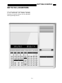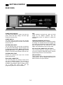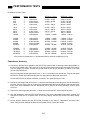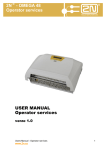
1
User’s Manual
Model SR715
Model SR720
LCR Meters
1290-D Reamwood Avenue
Sunnyvale, California 94089
Phone: (408) 744-9040 • Fax: (408) 744-9049
email: [email protected] • www.thinkSRS.com
Copyright © 1991 by SRS, Inc.
All Rights Reserved.
Revision 1.6 (02/2006)
TABLE OF CONTENTS
GENERAL INFORMATION
Safety and Preparation for Use
Specifications
Basic Operation
Passive Devices
Series and Parallel Circuit Models
Typical Measurement Setups
How the SR715/720 Works
Abridged Command List
Status Bytes
GETTING STARTED
SR715/720
Display
Keypad
Fixture
Rear Panel
iii
v
viii
viii
ix
x
xi
xii
xiii
1-1
1-2
1-3
1-5
1-6
2-4
2-4
2-4
2-4
2-4
2-6
2-6
2-6
2-7
2-8
2-8
2-9
2-9
2-10
2-10
2-11
Connecting a Device
Radial Leaded Parts
Axial Leaded Parts
Component Dimensions
2-12
2-12
2-12
2-13
Optional Fixtures
Fixture Adapter
Kelvin Clips
SMD Tweezers
BNC Adapter
2-13
2-13
2-14
2-14
2-15
Binning
Setting Up the Bins
Examples
Binning Worksheet
2-18
2-19
2-20
2-21
Option 01: GPIB Handler Interface
2-22
Conditions
Impedance Accuracy
R+Q Accuracy
L+Q Accuracy
C+D Accuracy
C+R Accuracy
Accuracy With Range Hold
2-1
2-1
2-2
2-2
2-3
Test Conditions
Default Conditions
Setting Test Conditions
Frequency
Output Voltage
Range
Autoranging
Range Hold
Constant Voltage
Bias
Internal Bias
External Bias
Measurement Rate
Settling Time
Triggering
Store and Recall
2-16
2-16
2-16
2-16
2-16
2-17
2-17
ACCURACY
OPERATION
Display
Displayed Parameters
Series & Parallel Equivalent Circuits
Display Types
Status & Binning
Open & Short Calibration
Suggestions for Calibration
Radial Fixture
Axial Fixture Adapter
Kelvin Clips
SMD Tweezers
Other Fixtures
PROGRAMMING
i
3-1
3-2
3-4
3-5
3-6
3-7
3-8
GPIB Communications
RS232 Communications
Front Panel LEDs
Command Syntax
Programming Errors
No Command Bit
4-1
4-1
4-1
4-1
4-2
4-2
Detailed Command List
Measurement Setup Commands
Measurement Control Commands
Measurement Result Commands
Binning Commands
Setup & Control Commands
Status Reporting Commands
Test & Calibration Commands
4-3
4-3
4-4
4-4
4-6
4-7
4-7
4-8
Status Byte Definitions
Serial Poll Status Byte
Standard Event Status Byte
LCR Status Byte
4-10
4-11
4-11
Program Examples
Microsoft C, Nat'l Instruments GPIB
Microsoft C, CEC GPIB
Binning
IBM BASIC, RS232
4-12
4-14
4-17
4-21
TABLE OF CONTENTS
External Bias Fuse
6-1
Functional Tests
Front Panel Test
Self Test
Output Voltage
Resistance Measurement
Capacitance Measurement
5-1
5-1
5-2
5-2
5-2
5-2
Error Messages
Operations Errors
Self-test Errors
Calibration Errors
6-2
6-2
6-2
6-4
Performance Tests
Frequency Accuracy
Amplitude Accuracy
Impedance Accuracy
Resistance Accuracy
Capacitance Accuracy
Performance Test Record
5-4
5-4
5-5
5-5
5-5
5-6
5-8
GPIB Problems
RS232 Problems
6-4
6-4
Fixture Maintenance
Cleaning
Removing Leads
Changing Radial Contacts
6-5
6-5
6-5
6-5
Calibration
Introduction
Calibration Enable
Calbytes
Amplitude Calbytes
Floating Point Calbytes
Amplitude Calibration
Frequency Calibration
Standard Resistor Calibration
5-10
5-10
5-10
5-10
5-11
5-11
5-12
5-13
5-13
SMD Tweezer Maintenance
Cleaning
Tip Replacement
6-7
6-7
6-7
PARTS and SCHEMATICS
TROUBLESHOOTING and
MAINTENANCE
Nothing Happens at Turn On
Reset
Internal Fuse
6-1
6-1
6-1
TESTS and CALIBRATION
Parts List
Schematic Diagrams
ii
7-1
7-13
SR715/720 LCR METER
SAFETY AND PREPARATION FOR USE
WARNING
Dangerous voltages, capable of causing injury or death, are present in this instrument. Use extreme caution
whenever the instrument cover is removed. Do not remove the cover while the unit is plugged into a live
outlet.
CAUTION
BIAS VOLTAGE ON CAPACITORS
This instrument may be damaged if operated with
the LINE VOLTAGE SELECTOR set for the wrong
AC line voltage or if the wrong fuse is installed.
Verify that polarized capacitors are installed with
the correct polarity before applying a bias voltage.
Failure to do so can result in damage to the unit,
the device under test, or possible injury. The
SR715/720 fixture and remote fixtures are marked
with '+' and '-' signs, or by red leads for the
positive connectors. Capacitors charged by an
external bias voltage should be discharged after
making the measurement. A 40 volt external bias
can charge a capacitor to a high enough voltage
that it can cause injury if it is accidentally
discharged. See the section on BIAS for more
information on how to safely apply external bias
voltage.
LINE VOLTAGE SELECTION
The SR715/720 operates from a 100V, 120V,
220V, or 240V nominal AC power source having a
line frequency of 50 or 60 Hz. Before connecting
the power cord to a power source, verify that the
LINE VOLTAGE SELECTOR card, located in the
rear panel fuse holder, is set so that the correct
AC input voltage value is visible.
Conversion to other AC input voltages requires a
change in the fuse holder voltage card position
and fuse value. Disconnect the power cord, open
the fuse holder cover door and rotate the fuse-pull
lever to remove the fuse. Remove the small
printed circuit board and select the operating
voltage by orienting the printed circuit board so
that the desired voltage is visible when pushed
firmly into its slot. Rotate the fuse-pull lever back
into its normal position and insert the correct fuse
into the fuse holder.
When connecting the external bias voltage to the
unit, observe the correct polarity and make certain
that the bias supply is floating (neither side is
connected to ground). Be certain to use a supply
current limited to 250 mA or less.
PROTECTION FUSES
In addition to the line fuse, the SR715/720 has two
other protection fuses. The external bias fuse
(3AG 0.25 A) is installed on the rear panel, next to
the bias terminals. If unstable readings occur
when making measurements with an external
bias, check this fuse. The other fuse is an output
protection fuse (2AG 0.25 A) located internally on
the main PCB. If unstable or erratic readings occur
or an 'outPut Err' (output err) occurs during self
test, this fuse may be damaged. See the
maintenance section for more information.
LINE FUSE
Verify that the correct line fuse is installed before
connecting the line cord. For 100V/120V, use a
1/2 Amp fuse and for 220V/240V, use a 1/4 Amp
fuse.
LINE CORD
SERVICE
The SR715/720 has a detachable, three-wire
power cord for connection to the power source
and to a protective ground. The exposed metal
parts of the instrument are connected to the outlet
ground to protect against electrical shock. Always
use an outlet which has a properly connected
protective ground.
Do not attempt to service or adjust this instrument
unless another person, capable of providing first
aid or resuscitation, is present. Do not install
substitute parts or perform any unauthorized
modifications to this instrument. Contact the
factory for instructions on how to return the
instrument for authorized service and adjustment.
iii
SR715/720 LCR METER
iv
SR715/720 LCR METER
v
SR715/720 LCR METER
GENERAL INFORMATION
The SR715/720 LCR Meters are multifrequency impedance measuring instruments, capable of measuring
resistance, capacitance or inductance over a range of more than 13 orders of magnitude. The SR720 has a
basic accuracy of 0.05% and has 5 test frequencies. The SR715 has a basic accuracy of 0.2% and 4 test
frequencies.
The LCR meters are controlled by a high speed microcontroller that operates the display, keypad, RS232 and
GPIB computer interfaces, and handler interface, as well as setting measurement conditions and performing
calculations. In addition, non-volatile storage is provided for 9 complete instrument settings.
SPECIFICATIONS
DISPLAY
Measurement Modes
Equivalent Circuit
Parameters Displayed
Averaging
Measurement Range
TEST CONDITIONS
Test Frequency
Drive Voltage
Drive levels accuracy
Measurement Rate
Ranging
Triggering
Bias Voltage
Auto, R+Q, L+Q, C+D, C+R
Series or Parallel
Value, Deviation, % Deviation or Bin Number.
Deviation and % deviation are calculated from a stored relative value.
2 - 10 Measurements
R+Q: R
0.0001 Ω - 2000 MΩ
Q
0.00001 - 50
L+Q: L
0.0001 µH - 99999 H
Q
0.00001 - 50
C+D: C
0.0001 pF - 99999 µF
D
.00001 -10
C+R: C
0.0001 pF - 99999 µF
R
.00001 - 99999 kΩ
100 Hz, 120 Hz, 1 kHz, 10 kHz, 100 kHz (100 kHz - SR720 only).
Frequency accurate to ±100ppm.
Preset Levels: 0.10, 0.25, and 1.0 Vrms.
Vernier: 0.1 to 1.0 Vrms with 50 mV resolution.
±2%.
Slow, Medium, Fast: 2, 10, or 20 measurements per second at test
frequencies of 1 kHz and above and about 0.6, 2.4, or 6 measurements per
second at 100 Hz and 120 Hz.
Auto or Manual
Continuous, Manual, or Remote over RS232, GPIB or Handler Interface
Internal:
2.0 VDC ±2%
External :
0 to +40 VDC (fused @ 0.25 A)
vi
SR715/720 LCR METER
ACCURACY
Conditions
Basic Accuracy
At least 30 minute warm up, 23 °C ± 5 °C.
SR715: 0.20%
SR720: 0.05%
See the Accuracy section for detailed accuracy specifications.
The table below summarizes the typical use accuracy.
Accuracy
better than 1%
SR720
0.125 Ω < R < 16 MΩ
2.5 µH < L < 25 kH
1.25 pF < C < 12.8 mF
SR715
0.143 Ω < R < 14 MΩ
2.9 µH < L < 22 kH
1.43 pF < C < 11.2 mF
better than 5%
21 mΩ < R < 96 MΩ
420 nH < L < 150 kH
0.21 pF < C < 77 mF
21 mΩ < R < 94 MΩ
426 nH < L < 150 kH
0.21 pF < C < 75 mF
The following conditions apply:
1) 1.0, 0.5 or 0.25 V output voltage
2) Slow or medium measurement speed
3) Q and D < 0.1 for R and C
4) Q > 10 for L
5) 100 Hz, 120 Hz or 1 kHz test frequency for R
6) 100 Hz test frequency for Lmax and Cmax
7) 10 kHz test frequency for Lmin and Cmin
FEATURES
Fixture
Protection
Zeroing
Compensation Limits
Binning
Self Test
Store and Recall
RS232 Interface
GENERAL
Operating Conditions
Power
Dimensions (W x H x L)
Weight
Warranty
4-Wire Kelvin fixture for radial leaded parts with adapters for axial leaded
parts.
Protected up to 1 Joule of stored energy, 200 VDC max (for charged
capacitors).
Fused at 0.25 A output current for biased measurement.
Open and Short Circuit Compensation.
Short: R < 20 Ω, Z < 50 Ω
Open: Z > 10 kΩ
Up to 8 Pass Bins, QDR and General Fail Bins, all defined from the front
panel or over the computer interfaces. Binning setups may be stored in nonvolatile memory.
Tests the ROM, CPU, Non-Volatile RAM, Clock Generator, A/D Converter,
Internal Bias, Multiplier, Output Drive Circuitry, Gain Circuitry, and Source
Resistances.
Stores 9 Complete Instrument Setups. Recall 0 recalls Default Setup.
All instrument functions can be controlled or read over the interface.
0 - 35 °C, <85% relative humidity.
20 Watts, 100/120/220/240 VAC, 50 or 60 Hz.
13.5" x 4" x 14" (343 x 102 x 356 mm)
10 lbs (4.55 kg)
One year parts and labor on materials and workmanship.
vii
SR715/720 LCR METER
OPTIONS
GPIB / Handler Interface
Option 01 provides both an IEEE-488 interface and a Handler interface.
IEEE-488 Interface:
All instrument functions can be controlled or read
over the interface.
Handler/Sorter Interface:
DB25 male connector provides output lines
to indicate binning information and
instrument status and an input trigger line.
Output lines include 8 Pass Bins, QDR Fail
Bin, General Fail Bin, Busy, and Bin Data
Available. Output lines are Open Collector
and are rated to 40 volts. The trigger input is
negative edge triggered TTL and is
protected to +/- 15 Volts.
SR726 Kelvin Clips
Provides connection to devices that are not easily accommodated in the
fixture. Polarity is indicated for biased measurements. Connects to
SR715/720 fixture.
SR727 SMD Tweezers
Provides connection to Surface Mount Device parts. Polarity is indicated for
biased measurements. Connects to SR715/720 fixture.
SR728 BNC Fixture Adapter Provides a means to connect a remote fixture or other device to the
SR715/720. Connects to SR715/720 fixture and has four 1 meter BNC
cables. Polarity is indicated for biased measurements.
viii
SR715/720 LCR METER
BASIC OPERATION
This section is designed to help the user begin
making measurements with the SR715/720 LCR
meter and to familiarize them with some of its
features. For more information on the different
features, see the operations section.
The SR715/720 comes with a built in fixture for
measuring radial leaded components, like most
capacitors, and adapters for measuring axial
leaded components, like most resistors. To
measure a radial leaded component, remove any
adapters and put one lead of the component in
each side of the fixture. To measure an axial
leaded component, first install the fixture adapters.
Put the adapters on in the middle of each side of
the fixture, and then slide them until they are
separated by the appropriate distance. Insert the
one lead of the component into each side of the
fixture.
To operate the SR715/720, first verify that the
correct line voltage has been selected on the
power entry module on the rear panel (See page
1-3). Verify that no parts are in the fixture; the
unit's self test routines will fail if any components
are in the test fixture. After connecting the line
cord to the power entry module, switch on the
power switch, located on the rear right hand side
of the unit. The unit will display the ROM version
on the left display and the serial number on the
right display for about 3 seconds. Next, the unit
will begin its self test procedure. If all tests are OK,
'tESt PASS' will be displayed. See the
Troubleshooting section if the self test fails. Press
[Recall] [0] [ENTER], to recall the default setup.
This will set the unit as follows:
Parameter
Frequency
Drive Voltage
Bias
Measurement Rate
Averaging
Range Hold
Equivalent Circuit
Display
Trigger Mode
Binning
After changing the fixture configuration, it is a
good idea to perform an open and short circuit
calibration. See the operation section for
instructions. If the component leads are
excessively dirty or are coated with wax, clean
them before inserting them in the fixture. The
fixture contacts will usually make contact through
coatings, but can eventually get gummed up.
AUTO
1 kHz
1.0 Vrms
OFF
SLOW
OFF
OFF
SERIES
VALUE
CONT
OFF
If biased measurements are being made on
capacitors, be certain that the part is installed
with the correct polarity, as marked on the unit.
What is a passive device?
All non-ideal passive devices (resistors, inductors
and capacitors) can be modeled as a real
component (resistor) either in series or in parallel
with a reactive component (capacitance or
inductance). The impedance of these components
change as a function of frequency. The series and
parallel models are mathematically equivalent and
can be transformed back and forth with the
equations shown below.
At this point a part can be placed in the fixture and
measurements can be made. The unit will
automatically decide which type of component is in
the fixture (R, C or L), change to the correct range,
and display the part value with the correct units. If
any of the test conditions need to be changed for a
measurement, press the appropriate keys. Most
functions are easy to change, but if more
information is needed, see the operating section.
Usually one model is a better representation of the
device under operating conditions. The most
accurate model depends on the device and the
operating frequency. Certain devices are tested
under conditions defined by the manufacturer or
industry standard. For example, electrolytic
capacitors are often measured in series at 120 Hz
in the C+R mode, so the ESR (equivalent series
resistance) can be measured.
ix
SR715/720 LCR METER
Series and Parallel circuit models
Rs in capacitors is often referred to as ESR or
equivalent series resistance. It includes things like
dielectric absorption in addition to the ohmic
losses due to the leads. It is often listed on data
sheets for electrolytic capacitors used in switching
power supplies. At high frequencies, the ESR is
the limiting factor in the performance of the
capacitor.
component. A low Q indicates a nearly pure
resistor. Q varies with frequency. Q is commonly
used to describe inductors. With resistors, often all
that is stated is that the resistor has low
inductance.
The dissipation factor, D, is equal to 1/Q and is the
ratio of the real impedance to the imaginary
impedance. A low D indicates a nearly pure
capacitor. D is commonly used when describing
capacitors of all types.
The quality factor, Q, is the ratio of the imaginary
impedance to the real impedance. For inductors, a
high Q indicates a more reactively pure
x
SR715/720 LCR METER
Typical measurement setups
The table below lists suggested test conditions for various types of components. This is by no means the only
set of conditions for measuring, but is a good general "rule of thumb".
Setups for Measuring Typical Parts
Component
Type
Value
Parameter
Type
Equivalent
Circuit
Frequency
Unknown:
Any
Auto
series
1 kHz
Resistors:
< 1 kΩ
> 1 kΩ
R+Q
R+Q
series
series
1 kHz
100 or 120 Hz
< 10 µH
10 µH – 1 mH
1 mH – 1 H
>1H
L+Q
L+Q
L+Q
L+Q
series
series
series
series
100 kHz
10 kHz
1 kHz
100 or 120 Hz
<10 pF
10 pF – 400 pF
400 pF – 1 µF
> 1 µF
C+D
C+D
C+D
C+R or C+D
parallel
series or parallel
series
series
10 kHz
10 kHz
1 kHz
100 or 120 Hz
xi
SR715/720 LCR METER
How the SR715/720 Works
The SR715/720 measures the impedance of a
component by measuring the voltage across the
part and the current through it. This is done for
both the real and imaginary (90° phase shifted)
components of the signals. The complex ratio of
voltage to current is equal to the complex
impedance. The processor calculates the various
parameters that are displayed, R, C, L, Q or D.
The real and imaginary signals are obtained by
multiplying the voltage and current signals with a
reference signal in phase with Vs and one shifted
90 degrees from Vs. These signals are measured
by an integrating A/D converter which is read by
the microprocessor. These values are corrected
by calibration factors, converted to impedances
and finally converted to the appropriate
parameters for display by the processor.
The voltage across the part is generated by Vs.
Both the amplitude and frequency of Vs can be
set. This voltage is applied to the device under test
(DUT) through source resistance Rs, which varies
according to the measurement range. The current
flows to the virtual ground of A1, and through Rr,
the current conversion resistor. The output of A1
provides a signal proportional to the current, I x Rr.
The voltage across the DUT is measured with a
separate signal path providing a 4-wire Kelvin
connection.
xii
SR715/720 LCR METER
COMMAND LIST
VARIABLES
i,j
x
Integers
Real Number
MEASUREMENT SETUP
$STL(?) {i}
Set (query) settling time to between i=2 and i=99 milliseconds.
AVGM(?) {i}
Set (query) averaging on (i=1) or off (i=0).
BIAS(?) {i}
Set (query) DC bias to internal (i=1), external (i=2), or off (i=0).
CIRC(?) {i}
Set (query) equivalent circuit to series (i=0) or parallel(i=1).
CONV(?) {i}
Set (query) constant voltage mode on (i=1) or off (i=0).
FREQ(?) {i}
Set (query) drive frequency to 100Hz(0), 120Hz(1), 1kHz(2), 10kHz(3) or 100kHz(4).
MMOD(?) {i}
Set (query) measurement mode to continuous (i=0) or triggered (i=1).
NAVG(?) {i}
Set (query) number of measurements to be averaged from i=2 to i=10.
PMOD(?) {i}
Set (query) parameter mode to Auto(0), R+Q(1), L+Q(2), C+D(3), or C+R(4).
RATE(?) {i}
Set (query) measurement rate to Fast(0), Medium(1) or Slow(2).
RNGE(?) {i}
Set (query) measurement range to 100kΩ(0), 6.4kΩ(1), 400Ω,(2) or 25Ω(3).
RNGH(?) {i}
Set (query) range hold to enabled (i=1) or disabled (i=0).
VOLT(?) {x}
Set (query) drive voltage to 0.1V ≤ x ≤ 1.00V with 0.05V resolution.
MEASUREMENT CONTROL
PREL(?) {x}
Set (query) nominal parameter value for deviation and %deviation to x (Ω,F,H).
STRT
Starts a measurement.
STOP
Stops the current measurement.
*TRG
Same as STRT.
MEASUREMENT RESULT
OUTF(?) {i}
Set (query) the output format to verbose (0) or concise (1) ASCII, or verbose (2) or
concise (2) binary.
XALL?
Returns major and minor parameters plus bin number.
XBIN?
Returns bin number of current measurement.
XDLT?
Returns deviation between major parameter and nominal value.
XMAJ?
Returns value of the major parameter.
XMIN?
Returns value of the minor parameter.
XPCT?
Returns percent deviation between major parameter and nominal value.
BINNING
BCLR
BING(?) {i}
BLIM(?) i,j {,x}
BNOM(?) i {,x}
Clears nominal values and limits for all bins. All bins are closed.
Set (query) binning to enabled (i=1) or disabled (i=0).
Set (query) upper (i=0) or lower (i=1) limit of bin j (0-7) to x%.
Set nominal value of bin i to x.
SETUP CONTROL
*IDN?
*OPC(?)
*RCL i
*RST
*SAV i
*WAI
Returns the SR715/720 identification string.
Set bit in Standard Event Status byte when measurement complete.
Recall setting i.
Reset unit to default configuration.
Save current setup as setting i.
Wait until all measurements are completed before proceeding.
STATUS
*CLS
*ESE(?) {i}
*ESR? {i}
*PSC(?) {i}
*SRE(?) {i}
Clear all status registers.
Set (query) the Standard Event Status Byte Enable register to value i (0-255).
Query Standard Status byte. If i is included, only bit i is queried.
Set (query) power-on status clear bit to clear (i=1) or maintain (i=0) status values.
Set (query) the Serial Poll Enable register to value i (0-255).
xiii
SR715/720 LCR METER
*STB? {i}
SENA(?) {i}
STAT? {i}
Query Serial Poll status byte. If i is included, only bit i is queried.
Set (query) LCR Status Enable register to value i (0-255).
Query LCR Status byte. If i is included, only bit i is queried.
STATUS BYTE DEFINITIONS
SERIAL POLL
STATUS BYTE
STANDARD EVENT
STATUS BYTE
LCR
STATUS BYTE
bit
0
1
2
3
4
5
6
7
name
Ready
unused
unused
LCR
MAV
ESB
RQS/MSS
No Command
bit
0
name
OPC
1
2
unused
Query Error
3
4
unused
Execution err
5
6
7
Command err
URQ
PON
bit
0
1
2
3
name
Math Error
A/D Error
Overload
Underrange
4
Overrange
5
Out of Range
6
7
unused
mem err
usage
The SR7XX is ready to perform a measurement.
An unmasked bit in the LCR status register has been set.
The GPIB output queue is non-empty
An unmasked bit in the standard status byte has been set.
SRQ (Service Request)bit.
There are no unexecuted commands in the input queue
usage
Set by the OPC command when all measurements are
complete
Set on output queue overflow (Too many responses waiting
to be transmitted.)
Set by an out of range parameter, or non-completion of
some command due a condition such as an incorrect
operating mode.
Set by a command syntax error, or unrecognized command
Set by any key press
Set by power on
usage
Set on a floating point error.
Set when an A/D conversion fails.
Set when the gain stage is overloaded.
Set when a measurement is below the nominal range of
values for the present range.
Set when a measurement is above the nominal range of
values for the present range.
Set when the unit is unable to make a valid measurement on
the current range.
the stored settings were invalid on power up.
xiv
SR715/720 LCR METER
xv
GETTING STARTED
SR715/720 LCR METERS
This section of the manual provides an overall view
of the SR715/720. For detailed operating
information on specific features, see the Operating
and Programming sections.
1-1
GETTING STARTED
DISPLAY
the auto parameter mode. The % LED indicates
that the measurement is displayed as a relative
deviation from an entered nominal value. Units are
indicated by the LEDs located between the two
displays: Ω, kΩ, MΩ, µH, mH, H, pF, nF or µF. The
minor parameter is dimensionless (Q and D) or
has the units of Ohms for resistance, unless the
kΩ LED on the right is on. Status information
(REM, ACT and ERR) is shown to the right of the
minor parameter. Beneath the major parameter
display are indicators for entering binning values,
NOMinal, +LIMit and -LIMit.
The LED display shows measured values, entered
parameters, instrument status, and user
messages. There are two 5-digit LED displays and
25 indicator LEDs. When making normal
measurements, the major parameter (L, C, or R) is
shown on the left display and the appropriate
minor parameter (Q, D or R) is shown on the right
display. The number of displayed digits and the
location of the decimal points are automatically
adjusted according to the range and resolution.
The measured parameters (L, C, or R and Q, D, or
R) are indicated by the LEDs above each numeric
display. If the AUTO LED is also on, the unit is in
1-2
GETTING STARTED
KEYPAD
The keypad is used to select measurement
conditions and to enter values. LEDs indicate the
actual
measurement conditions.
BIAS
[Internal] selects a 2.0 VDC internal bias. [External]
selects an external bias source. Pressing the
active key ([Internal] when internal bias is already
selected or [External] when external is selected)
turns the bias off.
PARAMETER
The [R+Q], [L+Q], [C+D], [C+R], and [AUTO] keys
select the parameter being measured. The
selected parameter pair is indicated above the
major and minor parameters in the display. If
AUTO is selected, the unit will select the most
appropriate parameter pair and turn on the AUTO
LED above the major parameter display.
Note that the bias is used only for capacitance
measurements. Pressing either of these keys in
any other mode, including the auto mode, will
display the error "bias for C".
MEAS RATE
The [Rate] key selects a slow, medium or fast
measurement. These rates correspond to 2, 10, or
20 measurements per second at measurement
frequencies of 1 kHz or higher.
FREQUENCY
The [UP Arrow] and [DOWN Arrow] keys select
one of the following output frequencies: 100 Hz,
120 Hz, 1 kHz, 10 kHz or 100 kHz (SR720 only).
The LEDs indicate the selected frequency.
AVERAGE
The [Average] key places the unit in the averaging
mode. Pressing it a second time returns the unit to
the non-averaged mode. The number of readings
averaged is set to between 2 and 10 from the entry
display.
DRIVE VOLT
The [Select] key cycles through the three output
drive voltages, 0.1 V, 0.25 V and 1.0 V. The
selected voltage is indicated by the LEDs. If no
LED is on then the output drive voltage is in the
vernier mode.
RANGE HOLD
[Range Hold] holds the unit in its current
measurement range. Pressing the key a second
time returns the unit to autoranging or normal
The [Cons Volt] key places the unit in the constant
voltage mode.
1-3
GETTING STARTED
mode. The range can also be entered with the
numeric keys in the entry display.
NUMERIC KEYS [0]..[9], [.], [+/-]
The numeric keys enter parameters and are only
active when the unit is in the entry display.
EQUIV CIRCUIT
The [Equiv Circuit] key selects between a series or
parallel equivalent circuit model of the component
being measured.
STORE and RECALL
The unit can store up to 9 complete instrument
setups in non-volatile memory. To store the
present configuration as setup #n, press [Store] [n]
[ENTER] where n ranges from 1 through 9. To
recall an instrument configuration, press [Recall]
[n] [ENTER]. Recall 0 returns the instrument to its
default values.
DISPLAY
The [Display] key selects the parameter on the
display. Pressing [Display] cycles through the
following display types.
VALUE
the value being measured
DEV
the deviation of the value from an
entered value
%DEV
the percent deviation from the
nominal
ENTRY
for entering parameter values
BINS
the bin number when binning is
enabled
CALIBRATE
The [Calibrate] key allows access to a series of
calibration features and special configurable
parameters, including open/short circuit calibration,
standard calibration, settling time, vernier output
drive amplitude, and the internal self tests.
BIN#, NOMINAL and LIMIT
These keys are used to enter binning parameters.
The BINNING LED is on when binning is enabled
and the optional handler is active.
TRIGGER and MODE
The [Mode] key selects between continuous
(CONT),
or
triggered
measurements.
Measurements are triggered by the [Trigger] key,
the handler interface or either of the computer
interfaces.
Certain displays are not accessible unless data
has been entered. For example DEV and %DEV
are not available unless a nominal value has
already been entered. Also, BINS is not available
unless binning data has been entered.
<The [<-] (backspace) key is used for correcting
mistakes when entering numeric data. The [<-]
also serves as the LOCAL key. If the [<-] is held
down when the unit is powered on, the instrument
settings revert to the factory set defaults.
ENTER KEYS
[ž, µH, pF] [kž, mH, nF] [Mž, H, µF]
The three enter keys are used when entering
numeric parameters in the entry display, such as
nominal values of R, C, or L. The [Mž, H, µF] key
acts as a general purpose [ENTER] key for
parameters with units not listed on any key, such
as percent. This key is labeled on the panel above
the key.
1-4
GETTING STARTED
FIXTURE
Axial leaded devices (leads at opposite ends)
require the use of the axial fixture adapters.
A versatile test fixture is provided with the
SR715/720 that provides a 4 wire Kelvin
connection to most types of leaded devices. (A
Kelvin connection uses two wires to carry the test
current to and from the device and two
independent wires to sense the voltage across the
device.) This prevents the voltage drop in the
current carrying wires from affecting the voltage
measurement.
Surface mount (SMD) devices or components with
large or unusually shaped leads can be measures
with SMD tweezers or Kelvin Clips. A BNC adapter
is available for interfacing to remote fixtures.
If the device leads are dirty or coated with wax,
clean them before inserting them in the fixture.
See the maintenance section for information about
cleaning the fixture.
Radial leaded components (where the leads are on
the same side) are simply inserted into the test
fixture, one lead in each side.
Radial Fixture (with part)
Axial Fixture (with part)
1-5
GETTING STARTED
REAR PANEL
SW1
These switches set baud rate, parity and word
length for the RS232 interface. See the
programming section for details on setting the
interface.
POWER ENTRY MODULE
The Power Entry Module is used to fuse the line
power, select the input voltage, and filter high
frequency electrical noise.
POWER SWITCH
The power switch is located on the rear right side
of the unit. Depressing the front side of the switch
turns the unit on.
HANDLER INTERFACE (OPTION 01)
This provides control lines to a component handler
for sorting. The interface has an input trigger line
and output lines indicating bin data available, busy
and 10 separate bins. The connector is a male
DB25. See the Handler section for more detail.
EXTERNAL BIAS INPUT
The two banana plugs are the input connections
for the external bias voltage. The bias supply must
be floating and well filtered. Neither side can be
ground referenced. The applied voltage must be
40 VDC or less and current limited to 250 mA max
IEEE-488 (GPIB) CONNECTOR (OPTION 01)
This connector allows for computer control of the
unit over the GPIB or IEEE-488 interface. See the
programming section for more information.
EXTERNAL BIAS FUSE
Protects the external bias input from currents
greater than 250 mA.
SW2 (OPTION 01)
These switches set the instrument address for the
GPIB interface. See the programming section for
detail on how to set up the interface.
RS232 DB25 CONNECTOR
This connector allows for computer control of the
unit over an RS232 interface. The connector is
configured as a DCE (transmit on pin 3, receive
Computer serial adapter, which is usually a DTE,
use a straight thru serial cable. See the
programming section for more information.
1-6
OPERATION
DISPLAY
The SR715/720 displays both major and minor parameters simultaneously. In addition to the parameter
selection, the display type may also be specified. This allows results to be shown in engineering units,
deviation from a specified nominal value, or binned for sorting purposes. The display also shows values
entered from the keyboard while specifying the nominal value or bin limits. The status LED's indicate remote
programming status information.
DISPLAYED PARAMETERS
The Parameter keys ([R+Q], [L+Q], [C+D], [C+R], and [AUTO]) determine the measurement type and the
displayed parameters. The selected parameters are indicated above the two 5 digit displays.
R+Q
Resistance is shown on the major parameter (left) display and the quality factor,
Q, on the minor parameter (right) display. The resistance is either the equivalent
series or parallel resistance of the device under test. The units of resistance are
Ω, kΩ, or MΩ. Q is the ratio of the imaginary part of the impedance to the real
part of the impedance and is dimensionless. Q is the same for both series and
parallel representations. If Q is positive, the reactive component of the device
under test is inductive. If Q is negative, the reactive component is capacitive.
L+Q
Inductance is shown on the major parameter (left) display and the quality factor,
Q, on the minor parameter (right) display. The inductance is either the equivalent
series or parallel inductance of the device under test. The units of inductance are
µH, mH or H. Q is the ratio of the imaginary part of the impedance to the real part
of the impedance. Q is dimensionless and the same for both series and parallel
representations. If the major parameter (inductance) is negative, then the part
under test is capacitive.
C+D
Capacitance is shown on the major parameter (left) display and the dissipation
factor, D, is shown on the minor parameter (right) display. The capacitance is
either the equivalent series or parallel capacitance of the device under test. The
units of capacitance are pF, nF, or µF. D is the ratio of the real part of the
impedance to the imaginary part of the impedance, or 1/Q. A good capacitor has
a large C (imaginary) and a small R (real) and thus a low D. If the major
parameter (capacitance) is negative, then the part under test is inductive.
C+R
Capacitance is shown on the major parameter (left) display. The equivalent series
or parallel resistance is shown on the minor parameter (right) display. The units
for resistance are Ω unless the kΩ LED to the right of the minor parameter
display is on.
AUTO
The SR715/720 determines which component model is the most accurate
representation of the device under test and chooses the appropriate parameter
pair. The determination is made as follows:
If |Q| < 0.125 the unit selects R+Q.
If Q > +0.125 the unit selects L+Q.
If Q < -0.125 and the unit is in the series mode, it selects C+R.
If Q < -0.125 and the unit is in the parallel mode, it selects C+D.
2-1
OPERATION
SERIES and PARALLEL EQUIVALENT CIRCUITS
Any non-ideal component can be represented as a resistive component either in series or in parallel with a
reactive component. Depending upon the characteristics of the component and the measurement frequency,
either the series or parallel model will be the more accurate model. The more ideal a component is, the less
the two models differ. However, as Q for inductors decreases towards 10 and Q for resistors or D for
capacitors increases towards 0.1, the series and parallel values begin to diverge. In general, most parts are
best approximated by the series model. Manufacturers often specify which representation should be used
when testing their devices. MIL or industry standards also specify test conditions.
The [Equiv Circuit] key toggles between the two equivalent circuit models. The SERIES or PARALLEL LEDs
indicate which model is active. For the series model, the left display shows the series resistance, inductance,
or capacitance (for R+Q, L+Q, C+D and C+R). The right display will show the quality factor Q, the dissipation
factor D, or the series resistance. For the parallel model, the left display shows the parallel equivalents of the
major parameters (R, L, or C) and the right display shows Q, D, or the parallel resistance. Q and D are the
same for both the parallel and series models.
DISPLAY TYPES
The [Display] key cycles through the five different display types. To cycle between the different displays, press
the [Display] key repeatedly until the appropriate indicator LED is on. Some of the display types are not
enabled unless the instrument is set appropriately. For example, only the Value and Entry displays are
enabled when the instrument is in the AUTO mode.
VALUE
The value display shows the value of the component being measured. The type
of component is indicated by the LEDs above the display (R+Q, L+Q, C+D, C+R).
The units of each display are indicated by the unit LEDs to the right of the each
display. The AUTO LED indicates that the auto select parameter (AUTO) mode is
active. The Value display is enabled under all conditions.
DEV
The DEV, or deviation display, shows the difference between the component
being measured and a previously entered relative value (display =
measured value - relative value). This is useful for measuring small variations in
component values. The DEV display is disabled if the unit is in AUTO mode or if
no nominal value has been entered. To use the DEV display, first enter a nominal
value (see below), then press the display key until the DEV LED is on. Negative
readings mean that the measured value is smaller than the nominal value.
Positive readings mean the measured value is larger than the nominal value.
Entering a Nominal Value
To enter a nominal value, press the [Display] key until the ENTRY display is
selected. Next, press the appropriate parameter key, [R+Q] for nominal
resistance values, [L+Q] for nominal inductance values, and either [C+D] or [C+R]
for nominal capacitance values. The appropriate parameter LEDs will turn on and
the present nominal value (or the default value) will appear in the left display. The
right display will be blank. Enter the new nominal value using the numeric keys
and one of the three enter keys [Ω,µH,pF], [kΩ,mH,nF], or [MΩ,H,µF].
%DEV
The %DEV, or percent deviation display, shows the % difference between the
component being measured and a previously entered nominal value (display =
100 x {measured value - nominal value} / nominal value). Percentages are
displayed to 0.1%. As with the DEV display this display is disabled if the unit is in
AUTO mode or if no nominal value has been previously entered. To enter a
nominal value, follow the proce dure described above.
2-2
OPERATION
ENTRY
The ENTRY display allows entry of nominal values, measurement conditions, and
calibration data. To view this display, press the [Display] key until the ENTRY LED
is on. If an out of range or incorrect value is entered, the unit will beep and display
'rAnGE Error' (range error) and not accept the value. The ENTRY display is
enabled under all conditions.
BINS
The BINS display shows the bin number that a component falls into when binning
is enabled. The display is disabled unless binning information has already been
entered. The BINS display is also disabled when the unit is in the AUTO mode.
To view the BINS display, first enter binning information and then press the
[Display] key until the BINS LED is on. See the section on binning for more
information
AVERAGE
The AVERAGE display shows the arithmetic average of two to ten
measurements. Averaging improves accuracy by cancelling out random errors
and noise. This is useful for measurements at the extreme end of a measurement
range or with low output signal levels. The number of measurements to be
averaged is set in the ENTRY display. From the ENTRY display, press the
[Average] key. The unit will display AvG in the left display and the present number
of averages in the right display. Set the desired number of averages (2 thru 10)
and press the [ENTER] ([MΩ,H,µF]) key. Return to the desired display type using
the [Display] key. Pressing the [Average] key toggles between averaging enabled
and disabled. The AVERAGE LED indicates that averaging is enabled.
AVERAGE works for all display types, including binning. In the BINS display, the
bin number displayed is the bin number of an average of several measurements,
NOT the average bin number.
STATUS
These LEDs indicate the computer interface status. REM (remote) indicates that the unit is under remote
interface control (front panel inactive). ACT (activity) indicates the computer interface is active. ERR (error)
indicates that a command sent to the instrument contained an error.
BINNING
The NOM, +LIM and -LIM LEDs indicate which parameter is being entered while configuring the SR715/720
for binning. See the section on binning for more details.
2-3
OPERATION
TEST CONDITIONS
DEFAULT CONDITIONS
If the back space key [<-] is held down while turning on the unit, it will be set to the default setup shown below
Any user calibrations are lost and factory calibrations are used. Using [Recall] [0] [ENTER] will set the
unit to the conditions below without disturbing any user calibration values.
Parameter
Frequency
Drive Voltage
Bias
Measurement Rate
Averaging
Range Hold
Equivalent Circuit
Display
Trigger Mode
Binning
AUTO
1kHz
1.0V
OFF
SLOW
OFF
OFF
SERIES
VALUE
CONT
OFF
SETTING TEST CONDITIONS
Test conditions are set two ways. Most of the major test conditions are set using a direct key press. These
conditions have dedicated keys that change their values or settings. Other conditions are set through the
ENTRY display, including the number of averages, range, and relative values for deviation measurements. To
adjust these conditions, use the [Display] key to select the ENTRY display and press the key of the parameter
to be changed. A message indicating which parameter has been selected will appear on the left display and
the present value of the parameter will be shown on the right display. Input the new value using the numeric
keys and use the unit keys or the [ENTER] key to enter the value. Return to the desired display with the
[Display] key. If an illegal value is entered when changing the test conditions, the unit will beep and display
'rAnGE Error'. If this occurs the unit will disregard the entry and allow another value to be entered.
The [Calibrate] key is used to access a series of less often used functions. They are 'vtESt' (vernier test
voltage), 'SEttL' (settling time), 'nuLL cAL' (null or open and short circuit cal) and 'SELF tESt' (self test). To
access these functions, press the [Calibrate] key until the desired function appears. A message will appear
along with the present value of that parameter. The new value is entered in the same manner as with the
ENTRY functions.
FREQUENCY
There are five selectable frequencies for the SR720 (four for the SR715): 100 Hz,
120 Hz, 1.0 kHz, 10 kHz, and 100 kHz (SR720 only). The output frequency is
accurate to 100ppm (0.01%). Frequencies are set by pressing either the [UP
Arrow] or [DOWN Arrow] key in the FREQUENCY section until the desired
frequency LED is on. If the unit is in range hold on range 0, the 100 kHz
frequency is disabled. If 100 kHz is selected while in range 0, the unit will beep
and a 'r-f Error' (range - frequency error) will occur.
OUTPUT VOLTAGE
There are three primary output drive voltages that can be selected as well as a
verniersetting with 50mV resolution. The primary voltage levels are 0.10 Vrms,
0.25 Vrms and 1.0 Vrms. The vernier settings range from 0.1 Vrms to 1.0 Vrms.
The accuracy of the output voltage levels is 2 %. The primary output levels are set by pressing the [Select] key
until the desired output level LED is set. The vernier setting is programmed using the CAL menu. Press
[Calibrate] until the left display shows 'vtESt'. The right display will show the present output voltage. Although
the unit will accept 3 digits, it will round the entered voltage to the nearest 50 mV. When the output voltage has
2-4
OPERATION
been programmed with the vernier setting, none of the primary drive voltage LEDs will be on. To return to the
primary output levels, press the [Select] key. The output voltage will be increased to the next highest primary
level.
The output voltage is applied to the device under test through a source
impedance, thus, the voltage across the device is always less than or equal to the
output voltage. The different source impedances are 25 Ω (R3), 400 Ω (R2),
6.4 kΩ (R1), and 100 kΩ (R0), all accurate to 2 %. The source impedance is
selected as a function of the measurement range, unless the unit is in constant
voltage mode. In the constant voltage mode, the source impedance is always
25 Ω. See the next section for determining which measurement range the unit is
using.
Voltage Across DUT vs DUT Impedance
For Different Ranges
Normalized to 1.0 Volt
1.0
R3 or
CV
0.8
R2
R1
R0
0.6
Volts
0.4
0.2
0.0
10 -1
10 0
10 1
10 2
10 3
10 4
10 5
10 6
10 7
10 8
DUT Impedance
The graph above shows the voltage across the Device Under Test (DUT) vs the
DUT impedance for the different measurement ranges. The values are
normalized to a 1.0 V output drive setting; for different applied voltages simply
scale the graph values by the applied voltage. Note that the voltage applied to the
DUT is nearly equal to the output voltage at the upper end of each range and
decreases with lower impedance toward the lower end of the range. This is
because of the output source impedance. If the unit is in constant voltage (CV)
mode, the source impedance is always set to 25 Ω. For any impedance
significantly larger than 25 Ω, the voltage across the part is essentially equal to
the output drive voltage.
For most devices, including resistors, most capacitors and many inductors, the
1.0 Vrms setting is the most appropriate setting. For some inductors and active
devices, such as diodes and transistors, the 0.25 or 0.10 Vrms setting should be
used. Certain devices require a specific test voltage, such as Z5U ceramic disk
2-5
OPERATION
capacitors (test voltage = 0.5 Vrms). In these cases, use the vernier setting to
obtain the exact voltage required. In general use the largest voltage possible for
the best signal to noise ratio and accuracy.
RANGE
The SR715/720 has 4 measurement ranges (0-3). The range may be selected
manually or the unit can autorange. The table below specifies the impedance
ranges for each of the measurement ranges. Each of the four ranges has source
impedance of approximately the mid-scale impedance. Note that the
measurement ranges determine an impedance range (not a value range), so the
ranges of inductance and capacitance depend upon the test frequency. The
parameter f is the test frequency. In addition, the impedance of capacitors is
inversely proportional to its capacitance, so larger capacitors are measured in the
lower impedance ranges.
Measurement Range and Impedance Range
Meas
Range
3
Source R
25.0 Ω
Resistance
10 µΩ 100 Ω
Inductance
0.0001 µH 15.9/f H
Capacitance
99999 µF 1.59/f mF
2
400 Ω
100.0 µΩ 1.6 kΩ
15.9/f H 256/f H
1.59/f mF 99.5/f µF
1
6.4 K Ω
1.6 kΩ 25.6 kΩ
256/f H 4074/f H
99.5/f µF 6.22/f µF
0
100 K Ω
25.6 kΩ 2000 MΩ
4074/f H 99999H
6.22/f µF 0.00001 pF
F is test
frequency
AUTORANGING
During normal operations the unit automatically changes to the most accurate
range for the device under test. When the unit measures an impedance that is
out of its current range, it goes up or down one range, and makes another
measurement. If this measurement is within the current range it displays it; If not,
it changes ranges (if available), and repeats this process. There is built in
hysteresis to avoid repeated range changes when a component is on a range
boundary. Up range changes occur when the impedance measured exceeds
450% of the midscale impedance (i.e. the source impedance), or 12.5% over the
nominal range limit. Down range changes occur when the measured impedance
drops below 22% of the midscale impedance, or 12.5% below the nominal range.
See the table below for the actual values where the range changes occur.
Range Change Points When Autoranging
Ranging To Lower Impedances
Range Change
Impledance
2 to 3
Z < 88 Ω
1 to 2
Z <1.4 kΩ
0 to 1
Z < 22.4 kΩ
RANGE HOLD
Ranging To Higher Impedances
Range Change
Impledance
3 to 2
Z > 115 Ω
2 to 1
Z > 1.8 kΩ
1 to 0
Z > 29.9 kΩ
It is sometimes desirable to disable autoranging since it takes nearly a complete
measurement cycle each time a range changes occurs. This can be annoying if
there are no parts in the fixture and the unit is continuously triggering, since an
empty fixture appears as a very large (nearly infinite) impedance. The unit will
2-6
OPERATION
autorange to range 0 (or range 1 for 100 kHz) and then autorange back to the
appropriate range when a part is inserted in the fixture. Range holding is helpful if
measurement speed is a concern or if a number of parts with similar values are
being measured.
There are two ways to range hold. The present measurement range can be held
by simply pressing the [Range Hold] key. The LED above the [Range Hold] key
indicates that the unit is in range hold. A measurement range can also be directly
entered from the ENTRY display. Select the ENTRY display using the [Display]
key, then press [Range Hold]. The message 'rAngE' will appear in the left display,
and the present range, 0-3, will appear in the right display. Enter the desired
range and press the [ENTER] key. Use the [Display] key to return to the desired
display. The range hold LED will be on. If an invalid range is entered, the unit will
beep and display the message 'rAngE ErrOr' and not accept the range entry.
Range 0 cannot be entered when the frequency is set to 100 kHz (SR720 only). If
this is attempted the unit will beep and display an 'r-f Error' (range - frequency
error).
To return the unit to autoranging mode, simply press the [Range Hold] key.
If the impedance of a part is more than 100 times the nominal value for the range,
the instrument indicates an 'ovEr rAnGE' (overrange) error. If this occurs, choose
a more appropriate range for the measurement. Measurement accuracy is
reduced if a component is measured outside of its optimal range. The accuracy of
an out-of-range measurement is as follows: for each factor of 2 outside of the
nominal range, the total error increases by the basic error. For example, if a part
is 4 times greater than the nominal range (2 factors of 2), then the total error will
be the basic accuracy + 2 x the basic accuracy. In this case, the total error
increases to 3 x the basic error. For more information, see the accuracy section.
CONSTANT VOLTAGE
Occasionally, a test will require using a specific drive voltage that is not possible
using the normal source resistance for that measurement range. In these cases,
use the [Cons Volt] key to set the source impedance to a fixed 25 Ω. The voltage
across the DUT will be almost constant for all devices with impedances
substantially larger than 25 Ω. When the unit is in constant voltage mode, the
measurement ranges change to avoid overloading the unit. However, it also
reduces the accuracy of the measurement by a factor of 2. See the accuracy
section for more detail. The table below lists the impedance ranges when using
Constant Voltage.
Measurement Range and Impedance Range
Meas
Range
3
Source R
25.0 Ω
Resistance
10 µΩ 360 Ω
Inductance
0.0001 µH 57/f H
Capacitance
99999 µF 442/f µF
2
25.0 Ω
360 µΩ 5.76 kΩ
57/f H 917/f H
442/f mF 27.6/f µF
1
25.0 Ω
5.76 kΩ 90.0 kΩ
917/f H 14324/f H
27.6/f µF 1.77/f µF
0
25.0 Ω
90.0 kΩ 2000 MΩ
14324/f H 99999H
1.77/f µF 0.00001 pF
f is test
frequency
2-7
OPERATION
Range Change Points When Autoranging
Ranging To Lower Impedances
Impledance
Range Change
2 to 3
Z < 315 Ω
1 to 2
Z <5.04 kΩ
0 to 1
Z < 78.8 kΩ
Ranging To Higher Impedances
Range Change
Impledance
3 to 2
Z > 400 Ω
2 to 1
Z > 6.4 kΩ
1 to 0
Z > 100 kΩ
Under certain conditions the 'ovEr LoAd' message will be displayed. This normally
occurs when the unit is in constant voltage with the range hold on. To correct this,
simply change to a higher impedance range, or autorange.
BIAS
Internal or external DC bias voltages can be applied to capacitors. Electrolytic and
tantalum capacitors need a positive bias for accurate measurements, although
the SR715/720 bipolar test voltage will not typically be enough to damage them.
The 2 VDC internal or up to 40 VDC external bias voltage allows measurements
to be made while approximating actual operating conditions. The external bias
capability also allows C-V measurements to be made on semiconductor devices.
Always make certain that the capacitor being tested is inserted with the correct
polarity. The bias voltage is always positive to the right and is marked on the
SR715/720. Failing to observe the correct polarity can result in the
destruction of the DUT and possible injury. Be aware that charged capacitors
can hold their charge for a long time if removed from the fixture without
discharging the DC bias voltage. Care must be taken to discharge the capacitors
after making measurements, ESPECIALLY WHEN USING EXTERNAL BIAS
WITH LARGE VOLTAGES!! Failing to discharge the device can result in damage
to the device, damage to the SR715/720, or possible injury!! The SR715/720 is
protected internally against discharging capacitors with up to 1 Joule of stored
energy (C•V2 /2).
The internal and external bias circuitry will work only if the unit is in the C+D or
C+R mode. Bias cannot be applied if the unit is in the R+Q, L+Q or the AUTO
mode. The error message of "biAS for c" will appear if the bias key is pressed in
the inappropriate mode. Whenever the bias circuitry is active the unit is in the
constant voltage mode so that the voltage across the capacitor under test will
stabilize in a reasonable amount of time. See the constant voltage section for
effects on ranges and accuracy.
It will take a short while for the internal circuitry and the DUT to stabilize after
applying the bias voltage. The time is primarily determined by the RC time
constant of the source resistance and the capacitor under test plus the internal
AC coupling capacitor of .47 µF. During this time the reading on the SR715/720
may change if it is continuously triggered. In this case, the initial readings should
be disregarded. If this is a problem, use the triggered mode (simply wait a short
time before triggering) or increase the settling time. See the section on
measurement rate for information on how to set the settling time. In addition, the
capacitance of some capacitors will slowly drift after a change in DC voltage.
INTERNAL BIAS
To apply the 2.0 VDC internal bias voltage, first verify that the capacitor is
installed with the correct polarity in the test fixture (positive to the right). Press the
[Internal] bias key to apply the bias voltage. After a second or two the reading
should be stable. Press the [Internal] bias key a second time to switch off the bias
to discharge the capacitor before removing it from the fixture.
2-8
OPERATION
EXTERNAL BIAS
The SR715/720 has rear panel connections to allow an external bias voltage of
up to +40VDC to be applied across the DUT. This supply must be floating (neither
side connected to ground) and must be current limited to less than 250 mA. A
linear supply is recommended (vs. switching supply). The supply should be well
filtered, to remove ripple from the bias voltage. Connections to the bias supply are
made on the rear panel with two banana jacks. The red jack is the positive side of
the supply and the black, the negative. There is an internal diode within the unit to
prevent a negative voltage from being applied. The bias supply lines are fused
with a 250 mA fuse on the rear panel, next to the banana jacks. If the SR715/720
doesn't yield stable readings when the external bias switched is on, check this
fuse. If the bias supply is connected backwards, there is a good chance that the
bias supply fuse will blow. Provisions need to be made to discharge the bias
voltage from the capacitor under test before removing it from the fixture. In
general, external switches or discharging resistors need to be provided with the
bias supply to ensure safe operation.
To apply an external bias voltage, ensure that the bias supply is connected
correctly. Then verify that the capacitor is installed with the correct polarity in the
test fixture (positive to the right). Next press the [External] bias key to apply the
bias voltage. After a second or two, the reading should be stable. After the
measurement is complete, discharge the DUT before removing it from the fixture.
For occasional use (non production) with small capacitors (<500 µF) and low bias
voltages (<20 VDC), the SR715/720 can discharge the capacitor internally. Press
the [External] bias key to switch off the bias. The capacitor will then discharge
through the unit in the same manner as the internal bias. Another solution for
somewhat larger bias voltages and/or capacitors is to connect a resistor across
the terminals of the bias supply. Switch off the bias supply and allow the capacitor
to discharge through the resistor before removing it from the fixture. Make certain
the discharge resistor is rated to handle the steady state current that the bias
voltage will generate through it and that the supply can provide this additional
current. For larger capacitors or higher supply voltages it will be necessary to
provide external switches to remove the bias voltage and discharge the capacitor.
MEASUREMENT RATE
The SR715/720 has three measurement rates: slow, medium and fast. These
correspond to about 2, 10 and 20 measurements per second on the 1 kHz, 10kHz
and 100 kHz (SR720 only) frequencies and about 1/10 of that for 100 Hz and 120
Hz frequencies. The table below lists the maximum measurement rates for the
different test frequencies. These rates are attainable when the unit is not in
autorange mode, binning is disabled, and neither GPIB nor RS232 interfaces are
active. The measurement rate affects the accuracy, with slow and medium being
the most accurate and fast being the least accurate.
Measurement Range Number of measurements/sec
Frequency
100 kHz
10 kHz
1kHz
120 Hz
100 Hz
Slow
2.8
2.8
2.7
0.7
0.6
Medium
14
14
13
2.8
2.4
Fast
28
27
24
7
6
The actual measurement time can be calculated from the following equation.
Tmeas= Ts + [(Ni •1/f + Tdi + Trs + Td) • Nm] + Tcalc
2-9
OPERATION
where Ts = settling time, Ni = number of test frequency cycles used in the
measurement, f = test frequency, Tdi = deintegration time, Trs = resync time, Td
= delay time, Nm = number of submeasurements per measurement, and T calc =
calculation time. Tdi, Td and Tcalc are constants, Trs and f are set by the
measurement frequency. Ni and Nm are determined by the measurement rate
and Ts set by the user. See the table below for the appropriate values.
Nm
Slow
Medium
Fast
Ni
Slow
Medium
Fast
Trs
Tdi
Td
Tcalc
Ts
1/f
2 ms
2 ms
3 ms
2-99 ms
8
8
8
100, 120 Hz
20
4
2
1kHz
40
4
2
10 kHz
400
40
20
100 kHz
4000
400
200
In addition to these factors, the measurement time is increased when using
autoranging, binning or the GPIB or RS232 interfaces. Binning adds about
2.5 mS to the total measurement time. Autoranging adds n•( Tmeas - 1mS)
where n=number of range changes required and Tmeas is calculated above.
It is difficult to determine the exact amount of time added when using GPIB or
RS232 interfaces, since it is dependent on baud rate, the speed of the computer
and the software. It takes about 5 mS for the unit to respond to a command after
it is received and about 5 mS to format a response to send back over the
interface. In general, simple commands and responses, like setting the frequency
or checking what range the unit is on, can be returned in about 10 mS. Longer
responses, like XALL?, can take as long as 2 seconds over RS232. If
communications speed is critical, the binary data format, which reduces the
number of bytes transferred, can be used.
SETTLING TIME
Occasionally it is advantageous to delay making a measurement after the unit is
triggered. This allows bias voltages on capacitors to stabilize or contacts on a
handler to debounce. The settling time is set in 1 ms intervals from 2 to 99 ms. To
set the settling time, press the [Calibrate] key until the 'SEttL' message appears in
the left display and the present settling time value in the right display. Enter the
new settling time value, from 2 to 99, and press the [ENTER] key. If an illegal
value is entered the unit will beep and display 'rAngE Error'.
TRIGGERING
The SR715/720 can make measurements continuously or in response to a
trigger. To change the trigger mode, press the [Mode] key until the desired mode
LED is on, either CONT or TRIGGERED. In the continuous mode the unit will
trigger itself at its maximum measurement rate. In triggered mode, the trigger can
be from the [Trigger] key, from the RS232 or GPIB interfaces, or from the Handler
interface. While making a measurement, the unit will ignore any triggers it
receives until the current measurement is complete. The TRIG LED will flash
2-10
OPERATION
whenever the unit is triggered. In the triggered mode the unit will make a single
measurement per trigger.
STORE and RECALL
[Store] and [Recall] allow nine complete instrument setups to be saved in non-volatile memory. All the test
conditions, including binning configuration and open and short circuit compensation are saved.
Store
To store a setup, press the [Store] key, which will display the 'StorE' message in
the display. Press the number of the stored setting ([1] - [9]) and the [ENTER]
key. [Store] [0] [ENTER] will give an error since setup 0 is the factory default
setup.
Recall
To recall a stored setting, press the [Recall] key, which will display 'rcL'. Press the
number of the stored setting ([1] - [9]) and the [ENTER] key. [Recall] 0 returns the
default setup, including null cal values. If a 'CAL Err 4' appears during self test, or
a 'rcL Err' appears when recalling a setup, the stored setup was lost and must be
re-entered.
2-11
OPERATION
CONNECTING A DEVICE
The SR715/720 has a built in Kelvin fixture for measuring radial leaded components and adapters for
measuring axial leaded components. The fixture provides a 4-wire Kelvin connection to the device under test
to minimize stray impedances that cause measurement errors. Most components will fit into this fixture, thus
eliminating the need for special fixtures. Remember, whenever the fixture configuration is changed, open
and short circuit calibrations should be performed before making measurements. Open and short circuit
calibration values are stored in non-volatile memory with the [Store] and [Recall] keys along with the complete
instrument setup. This allows compensation values for different fixtures to be stored then recalled whenever
different measurement setups are required. Also remember that when measurements are in progress, keep
hands or any other objects away from the fixture because the measurement accuracy may be affected. There
is a cover beneath the fixture to catch any leads that might fall through the fixture. For information on removing
leads or general maintenance to the fixture in general, refer to the Maintenance section.
RADIAL LEADED PARTS To measure parts with radial leads, (leads coming out the same side of the
package) first remove any adapters or parts from the fixture, since they will
interfere with making a Kelvin connection. Next, make sure the leads are
reasonably clean of wax or other coatings. These can cause an unreliable contact
and gradually build up in the fixture. Insert one lead into each side of the fixture,
approximately centered and make the measurement.
AXIAL LEADED PARTS
To measure parts with axial leads, (leads coming out opposite ends of the
package) first remove any parts from the fixture. Install the axial adapters in the
center of each fixture half and slide them apart or together so the DUT will be
approximately centered in the fixture. Check that the leads are reasonably clean
and insert one lead in each side of the fixture adapter. After removing the axial
lead adapters, replace them in the two storage slots behind the fixture so as not
to misplace them.
Radial Fixture (with part)
Axial Fixture (with part)
2-12
OPERATION
COMPONENT DIMENSIONS The radial fixture can accommodate components with a lead spacing from
0.2" (5mm) up to 3.8" (96.5mm) with a minimum lead length of 0.16" (4mm). The
axial lead adapter can accommodate parts with a maximum body length of 2.7"
(68.6mm) and a maximum diameter of 1.8" (45.7mm). The closest the adapters
can get is 0.12" (3.0mm). The minimum lead length (of each lead) is 0.25"
(6.4mm). However the minimum length of the part and lead combined is 0.7"
(17.8mm). See the diagrams below. Lead diameter for either fixture configuration
can vary from 0.008" (.20mm or 32 AWG) up to 0.070" (1.8mm or 13 AWG).
OPTIONAL FIXTURES
ADAPTER
The Kelvin Clips, SMD Tweezers and BNC adapters all connect to the
SR715/720 fixture using the same adapter. To install the fixture adapter, first
remove any parts or adapters from the fixture. Then plug the fixture adapter into
the fixture, matching the polarity of the adapter to the polarity of the SR715/720.
Make certain that the center clips makes contact with the center guard ground.
2-13
OPERATION
KELVIN CLIPS
Kelvin Clips provide a simple means to measure large or unusually sized parts.
They can connect to any component lead up to 0.3" (7.6mm) in diameter. When
connecting the Kelvin Clips to a device, remember that the red lead denotes the
"+" side of the fixture if any biased measurements are made. Connect one clip to
each side of the component and perform the measurement. Whenever the fixture
configuration is changed, be sure to perform open and short circuit calibration.
Kelvin Clips will give the best results if they are used at frequencies of 1 kHz and
below and impedances of 1 MΩ or less. At higher frequencies, lead position and
other subtle conditions can change stray impedances, affecting measurement
accuracy. For measurements outside of these limits, a test fixture is advised.
SMD TWEEZERS
The SMD Tweezers provide a combination of test fixture and handling tweezers
for measuring surface mount devices. The tweezers make a Kelvin connection to
devices up to 0.4" (10.2mm) wide and make it easier to measure and sort these
small components. The parts tray in front of the fixture provides a convenient
place to place parts while sorting and measuring them. Connection of the SMD
tweezers to the SR715/720 fixture is the same as for the Kelvin Clips.
Remember, always perform open and short circuit calibration after changing the
fixture setup. The tweezers are marked with the same polarity as the fixture for
making biased capacitance measurements. (Some units do not have the polarity
2-14
OPERATION
marked. The side with the silkscreen is the positive side.) To make a
measurement, pick up the component with the SMD tweezers so that the
metallized ends of the parts contact the tips of the tweezers. The tips can be
replaced if they wear out or break. See the maintenance section for details on
changing them.
BNC ADAPTER
The BNC Adapter Set connects the SR715/720 to other test equipment, switching
networks, or remote test fixtures. The adapter connects to the test fixture in the
same fashion as the Kelvin Clips and SMD Tweezers. The four coax cables are
labeled: Ih (red), the + drive signal, Il (blue), the - drive signal, Vh (orange), the +
sense connection, and Vl (purple), the - sense connection. When connecting
these cables to a device, connect the two + signals to one side of the device and
the two - signals to the other side. The + leads have the same polarity as the
fixture when using DC bias signals. The shields of the four cables should not
connect to each other. The shields of the two drive connections (Ih and Il) should
be connected to each other and to a shield, case or guard at the fixture or DUT, if
possible. The shields of the sense signals (Vh and Vl) should float. If extension
cables are used, it is important that the connector shields do not make contact
with each other.
2-15
OPERATION
OPEN and SHORT CIRCUIT OR NULL CALIBRATION
Compensation of stray impedances is performed by open and short circuit or fixture null calibration. This
corrects for lead impedance, and fixture, cable and other stray capacitance. Null calibration corrects for all
frequencies and all ranges - it is not necessary to re-calibrate for changes in frequency. Null calibration should
be performed after any change in fixture configuration or for changes in the drive amplitude. For critical
measurements, null cal should be performed frequently, possibly several times a day. The open and short
circuit values are stored with the [Store] and [Recall] keys, allowing null calibration data to be saved for
different fixture configurations.
The Null Calibration procedure is in the CAL menu. Press the [Calibrate] key until the message 'nuLL cAL'
appears on the display. Press the [ENTER] key and the message will change to 'Short cAL'. Place a wire of
between 26 to 16 AWG (0.02" to 0.05" or 0.51 to 1.30 mm dia.) in the fixture. Press the [ENTER] key and
move hands and any miscellaneous objects away from the fixture. When the short circuit cal is finished, the
'oPEn cAL' message will be displayed. Remove the shorting wire, press [ENTER] and again move your hands
away from the fixture. When the unit has finished, the message 'cAL donE' will be displayed. Use the [Display]
key return to the desired display.
Suggestions for Calibration
It is always best to perform the null calibration in the same configuration that measurements will be made. This
will ensure that stray impedances will be cancelled out as completely as possible. Also, keep any objects away
from the fixture that will not be present during measurements, for example hands or pieces of metal. (To
observe the effect your hand has on impedances, place a small capacitor, ~10pF, in the fixture and observe
the change in measured capacitance as you move your hand closer to the fixture. This is due to your hand
disturbing the electric fields around the fixture). For high impedance measurements, the open circuit null will
be more accurate if the fixture contacts are clean. A piece of paper (the coarser the better) slid back and forth
between the contacts will clean them (if they are not too dirty).
RADIAL FIXTURE
Use a "U" shaped piece of copper wire, 26 to 16 AWG (0.02 to 0.05" or 0.51 to
1.30 mm dia.), 2"-3" long (50-80mm) for the shorting wire. Insert the shorting wire
in both sides of the fixture at about the same places that the component leads will
be inserted.
AXIAL FIXTURE ADAPTER Place the axial adapters in the desired locations on the fixture. For the shorting
wire, use a straight piece of wire or a lead (26-16 AWG) that fits in the contacts in
the same fashion as the parts to be measured do.
KELVIN CLIPS
It is more difficult to get an accurate null calibration with the Kelvin clips than with
a fixture, since their physical configuration is less controlled. As always, place
them as close to the measurement configuration as possible while making null
measurements. For the shorting measurement DO NOT connect the two clips
together. Connect the two clips to the same side of a DUT, ensuring the same
contact resistance that as in actual measurements. For the open measurements,
leave one clip attached to the DUT and position the other at about the same
2-16
OPERATION
separation as it will be when making measurements. Again keep hands or other
objects away from the clips while performing null cal. See the illustration above.
SMD TWEEZERS
SMD tweezers present a challenge to calibrate accurately, since their position can
vary and the operators hands are always present when making measurements.
Use a piece of copper (shorting block) about the same dimensions as the devices
to be measured, as the shorting wire. DO NOT just touch the tips together. A
shorting block can be made from an SMD device by connecting the two ends with
copper tape or solder to create a short circuit. When performing open circuit cal,
hold the tips about the same distance apart as they will be when measuring parts
and keep your hands still. Sometimes it is valuable to check the "quality" of the
null calibration by measuring the part that was used to perform the null cal (the
shorting block). If the residual error is larger than the measurement can tolerate,
it may be necessary to re-do it until an acceptable calibration is achieved.
Other Fixtures
In general, follow the procedure for performing null cal as described above. Use a
configuration similar to one that will be used when making measurements and
keep any random objects far away.
2-17
OPERATION
BINNING
The SR715/720 has built in features to aid in component sorting. This is especially useful for production
testing, incoming inspection, device matching or tests where multiple devices of similar value must be
measured. The binning feature simplifies parts sorting by eliminating the need to read the major and minor
parameters and then deciding what to do with the part. [Store] and [Recall] allow up to 9 binning configurations
to be entered and saved making it easy to change between different setups. Binning configurations can also
be entered over one of the computer interfaces. The SR715/720 can sort components into as many as ten
separate bins - eight pass bins, a minor parameter failure bin, and a general failure bin. Binning operations
can either be performed from the front panel, in the BINS display, the standard RS232 computer interface or
the optional GPIB or Handler interface.
There are three different types of binning schemes that the SR715/720 supports: Pass/Fail, Overlapping, and
Sequential. Pass/Fail has only two bins; good parts and everything else. Overlapping or nested bins have one
nominal value and are sorted in progressively larger bins (+/-1%, +/-2%, +/-3%). Sequential bins can have
different nominal values, each separated by a percentage (.9*nom, .95*nom, 1.0*nom, 1.05*nom, with 5%
limits) or a single nominal value and asymmetrical limits (-3% to -1%, -1% to 1%, 1% to 3%). Limits are pairs
and can be symmetrical (+/-2%) or asymmetrical (-5% to -1%). Examples of different binning schemes are
listed below.
Nested Bins 100 Ω resistors sorted into progressively
looser symmetric limits pairs with a single nominal value.
Nominal value = 100 Ω
Bin0: +/-1%
Bin1: +/-2%
Bin2: +/-3%
Bin3: +/-4%
Bin8: QDR failure bin (if Q was too high)
Bin9: General Failure bin (parts that don't fall into
any other bin)
1. Sequential Bins 100 Ω resistors sorted into symmetric
1% limit pairs, each with a different nominal value.
Bin0: nom : 98.2 Ω +/-1%
Bin1: nom : 100 Ω +/-1%
Bin2: nom : 102 Ω +/-1%
Bin3: nom : 104 Ω +/-1%
Bin8: QDR failure bin (if Q was too high)
Bin9: General Failure bin
2. Sequential Bins 100 Ω resistors sorted with
asymetric limit pairs and a single nominal value.
Nominal value = 100 Ω
Bin0: -5% to -3%
Bin1: -3% to -1%
Bin2: -1% to +1%
Bin3: +1% to +3%
Bin8: QDR failure bin (if Q was too high)
Bin9: General Failure bin
2-18
OPERATION
Binning data can be entered manually using the [Bin#], [Nominal] and [Limit] keys, or over the RS232 or
optional GPIB interface. A bin is defined by a bin number, with a nominal value and upper and lower limits (in
percent). If a nominal value is not entered for a bin, it will take the nominal value of the next lower bin. Bin 0 is
the exception. If bin 0 doesn't have a nominal value and limits, all parts will fail. Parts that fall into more than
one bin are assigned to the lower numbered bin. Thus, the tightest tolerances should be assigned to the
lowest bin number. Any parts that fall into gaps between bins are assigned to the general failure bin (bin 9). If
only one limit of a pair is entered, the limits will be assumed to be a symmetric pair (+/- x %, where 'x' is the
entered limit value). Unused bins should be closed (assigned 0% limits). After bin clear or [Recall] [0], all bins
are closed. Parts that fall into both the general fail bin (bin 9) and the QDR fail bin (bin 8) are assigned to the
QDR fail bin. The QDR limits are maximums or minimums depending on which parameter is being measured.
If a Q value is negative, (for resistors) the absolute value should be entered, and the meter performs a
comparison between the absolute value of the QDR reading and the QDR limit. There are no limits for the
QDR bin, only a nominal value. To disable the QDR comparison, set the nominal value to its extreme value.
Parameter being measured
R+Q
L+Q
C+D
C+R series
C+R parallel
QDR Limit
Q maximum
Q minimum
D maximum
R maximum
R minimum
Extreme Value (disabled)
9999.9
0
9999.9
9999.9
0
SETTING UP THE BINS
INITIAL
NOMINAL VALUES
FOR PASS BINS (0-7)
LIMITS FOR
PASS BINS (0-7)
To enter binning information the unit can not be in the AUTO parameter mode.
Make certain that the unit is set to the correct parameter (R+Q, L+Q, C+D or
C+R). Press the [Bin#] key which will bring up the bin entry display and put the
unit in the entry mode. If any previous binning information needs to be cleared,
press the [Bin#] key until the 'bin cLEAr' message appears. Press the [ENTER]
key to clear all bin data and display 'cLEAr donE'. To enter new bin data or to edit
old bin data (if it wasn't previously cleared), press the [Bin#] key until the unit
displays 'bin x'. Enter the desired bin number ([0] thru [8] then [ENTER]). The bin
number will appear on the right display. This is the bin for which subsequent
nominal and limit values will be entered.
To enter the nominal value, press the [Nominal] key. The display will show the
present nominal value, or '-----' if the bin was previously closed in the left display.
The 'NOM' LED below the display will be on. If a nominal value is needed for this
bin, enter the desired nominal value with the numeric keys and the unit entry
keys. The new nominal value, including units will be displayed. Note that a
nominal value doesn't have to be entered for each bin. If a bin doesn't have a
nominal value it will use the one from the bin below it.
To enter the limits, press the [Limit] key. The display will show the present upper
limit value, or '---' if no limit existed previously. The +LIM LED below the display
will be on. Enter the limit value in percent using the numeric keys and the
[ENTER] key. If it is necessary to enter a non-symmetrical limit pair, press the
[Limit] key a second time to display the present lower limit value. The -LIM LED
will turn on. Enter the lower limit in the same fashion as the upper one. For
symmetric limits, enter only the upper value; the lower limit will be the negative of
the upper limit. If no limits are entered for a bin, that bin will remain closed, even if
it has a nominal value.
2-19
OPERATION
VALUES FOR
FAIL BINS (8 & 9)
ENABLE BINNING
To set the QDR limit value, select bin 8 (using the [Bin#] [8] [ENTER] keys) and
press the [Nominal] key. This will display the present QDR limit, or '-----', in the
right display and turn on the NOM LED. Input the value with the numeric keys and
press the [ENTER] key. Resistors for the C+R mode are entered in Ω (the
allowable range of resistance values is only 0 to 99999 Ω, so no kΩ or MΩ key is
needed). There are no limits for the QDR bin. Bin 9, the general failure bin,
cannot be set. Parts that do not fall into any other bin are assigned to this bin.
To enable or disable binning, press the [Bin#] key until the 'Sort oFF' or 'Sort on'
message appears. Pressing the [ENTER] key from this display toggles binning
(sorting) on and off. When binning is enabled, the BINNING LED is on, the BINS
display is active, and the handler interface (if installed) is active. The handler
interface is active whenever binning is enabled, whether or not the BINS display
is on. See that section for more information on the Handler interface.
Before entering binning information, it is usually better to write down the desired binning setup since it is a
fairly complicated procedure. See the binning worksheet on the next page. Also, be sure to save setups that
are used often. Certain setups can be edited, for example, one percent resistors using the same nominal
value. A different value of resistor could be sorted by simply changing the nominal value, if the only nominal
value entered was for bin 0. For this reason, it is often better to enter sequential binning data with a single
nominal value and different percentage limits, instead of with different nominal values (overlapping limits are
always entered in that fashion, so it isn't an issue for them). It is advisable to check the nominal values and
limits before making measurements, to be certain that they haven't been modified. The binning setup can be
viewed in the same manner as it was entered; just don't press the [ENTER] key unless a value needs to be
changed.
Examples
PASS/FAIL
NESTED OR
OVERLAPPING BINS
SEQUENTIAL BINS
Enter the nominal value and limits for bin 0. Enter the QDR fail value for bin 8.
Make sure no other bins are open (set their limits to zero). Parts that pass fall into
bin 0; all other parts fall into bin 8 or bin 9.
Enter the nominal value and limits for bin 0. For subsequent bins, enter only the
limits, making sure the tighter tolerance parts use the lowest bins. If the limits are
symmetrical, only enter the upper limit. Enter the QDR limit for bin 8. Make sure
all other bins are closed. Parts that pass fall into one of the pass bins. Parts that
fail the QDR test fall in bin 8 and parts that fall into no other bin fall into bin 9.
For sequential bins with a single nominal value, follow the same procedure as for
nested bins mentioned above. For sequential bins with multiple nominal values,
enter the nominal value and limits for each open bin. If the limits are symmetrical,
only enter the upper limit. Enter the QDR fail value for bin 8. Make sure that
unused bins are closed (limits set to zero) and there are no unwanted gaps
between bins. Parts that pass fall into one of the pass bins. Parts that fail the
QDR test fall in bin 8 and parts that fall into no other bin fall into bin 9.
2-20
OPERATION
Binning Worksheet
Date:
Nominal value of component:
Tolerance to be sorted to:
Entered by:
Type of binning:
bin #
__________
______________________
______________________
_______________________________________
Pass/Fail
nom
Nested
Sequential
+lim
-lim
xxxx
xxxx
xxxx
xxxx
0
1
2
3
4
5
6
7
8
9
xxxx
2-21
OPERATION
Option 01: GPIB/Handler Interface
GPIB Interface:
Detailed information on the GPIB interface and programming examples are available in the remote
programming section.
Handler Interface:
Introduction
The handler interface for the SR720/715 allows the unit to be operated with external hardware to measure and
physically sort components. Data lines for ten sorting bins are provided, as well as control lines (-START, BUSY, -BDA) to coordinate measurements. For more information on bin setup procedures and options, refer
to the binning section.
Timing Diagram:
(a)
The SR720/715 is waiting for a trigger to start measuring. Previous bin data (if any) is still available.
(b)
A negative-going pulse on the -START line will trigger a reading. The -BUSY line will go low and stay
low until the measurement is completed.
(c)
After measuring, the SR720/715 determines the proper bin to place the component. During this time
the -BDA (Bin Data Available) line is activated to prevent reading invalid data.
After the proper bin location has been selected, the -BDA line will go high, and the appropriate bin line
will be pulled low (only a single bin line will be low at any one time). The external handler can now remove the
component, place it in the specified location, and insert a new one into the fixture. The SR720/715 is now
again in state (a).
Note: some handlers can be instructed to remove the component under test to the sorting area as soon as the
-BUSY line goes high.
2-22
OPERATION
Mechanical Description:
The handler interface is part of the Option 01 GPIB/Handler board and is accessed via a 25 pin male
connector on the rear of the SR720/715. A DB25 female connector, metal housing, and plastic sheath have
been provided to simplify construction of a cable to the external handler.
Connector pinouts are as follows:
Bin 0:
Bin 1:
Bin 2:
Bin 3:
Bin 4:
Bin 5:
Bin 6:
Bin 7:
Bin 8:
Bin 9:
-BUSY:
-BDA:
-START:
Also:
+5 supply
GND
Pin #
13
25
12
24
11
23
10
22
9
21
8
20
3
pins 7 and 19
pins 6 and 18
Electrical Description:
The trigger input (-START) line is active low and requires a pulse width of at least 50ns to activate (edgetriggered). 1N4148 diodes protect against voltages exceeding TTL levels. Outputs are provided by 7406
inverting buffers which have open-collector outputs and therefore need pull-up resistors for proper operation.
NOTE:
Maximum High-level output voltage: 30 V
Maximum Low-level output current: 40 mA
Example: When connecting the output to a 5V supply, the pull-up resistor should be no smaller than 5V/40mA
= 125 ohms.
Flyback diodes should be added if the outputs are used to drive relay coils, but such a direct connection is not
recommended. Ideally, opto-isolators should be used on all data lines to prevent noise from the handler from
interfering with measurements.
2-23
ACCURACY
DETAILED ACCURACY SPECIFICATION GUIDE
CONDITIONS
The following conditions must be met for the unit to meet its accuracy specifications
1)
2)
3)
4)
5)
Warm up time: > 30 minutes
Temperature: 23 ± 5 °C
Fixture: Built in
Open & Short Circuit Calibration have been performed
D < 0.1 for Capacitance Measurements
Q < 0.1 for Resistance Measurements
Q > 10 for Inductance Measurements
ACCURACY EQUATIONS
The accuracy of a measurement is a function of the basic accuracy at that frequency, measurement rate, the
signal amplitude, and where the impedance of the DUT is within the measurement range. The basic accuracy
can be determined from the impedance graph or from the individual parametric graphs. Additional factors are
determined by the measurement conditions and the impedance of the DUT. From these, the accuracy of a
measurement in its optimal range can be calculated. See the following section for effects due to
measurements made out of an optimal range.
3-1
ACCURACY
IMPEDANCE ACCURACY
Accuracy of Z = ± [A x Ki x Kv + (Kh + Kl) x 100] %
A
=
Ki
=
Kv
=
Kh, Kl
=
Basic Impedance Accuracy Factor
from graph on next page.
If the unit is in the constant voltage
(CV) mode, double the basic
accuracy factor.
Integration Time Factor (see Ki
Table below)
Drive Voltage Error Factor
(see Kv Table below)
Extreme Range Error Term (see
Kh,Kl Table below)
Ki Table
Meas Rate
slow,med
fast
fast
Kh & Kl Table
Frequency
Zm
all
100 Hz-1 kHz 6.25 Ω<Zm<400 kΩ
all other
Frequency
Kl
100,120,1k Hz (1 mΩ / Zm)
Ki
1
3
2
Kv Table
Vout (V rms)
1.0 - 0.55
0.5 - 0.3
0.25 - 0.15
0.10
10 kHz
(1 mΩ / Zm)
Kh
(Zm / 2 GΩ)
(Zm / 1.5 GΩ)
100 kHz
(4 mΩ / Zm)
(Zm / 50 MΩ)
Zm = the impedance of the device being
measured.
Kv
1 / Vout
0.5 / Vout
0.25 / Vout
0.11/Vout
Note that Kl is negligible for impedances above
100 Ω and Kh is negligible for impedances below
1 kΩ, both at all frequencies.
Note that Kv equals one for the primary drive
voltages (1.0, 0.5 and 0.25 Vrms).
3-2
ACCURACY
3-3
ACCURACY
R + Q ACCURACY
Accuracy of R = ± [A x Ki x Kv + (Kh + Kl) x 100] %
A
=
Ki
=
Kv
=
Kh, Kl
=
Basic Resistance Accuracy Factor
from graph.
For |Q| > 0.1, multiply the basic
accuracy factor by (1 + |Q|).
If the unit is in the constant voltage
(CV) mode, double the basic
accuracy factor.
Integration Time Factor (see Ki
Table below)
Voltage Error Factor (see Kv table
below).
Extreme Range Error Term (see
Kh, Kl table below).
Accuracy of Q = ± [(Ar / 100) x (1 + Q2)]
Ar
=
the accuracy of the Resistance
measurement (above)
Note that the accuracy of Q is specified as a
magnitude, NOT as a percent.
Ki Table
Meas Rate
slow, med
fast
fast
Frequency
Zm
all
100 Hz-1 kHz 6.25 Ω<Zm<400 kΩ
all other
Ki
1
3
2
Kh & Kl Table
Zm = the impedance (resistance) of the device
being measured.
Frequency
Kl
100,120,1k Hz (1 mΩ / Rm)
Kv Table
Vout (V rms)
1.0 - 055
0.5 - 0.3
0.25 - 0.15
0.10
Kv
1 / Vout
0.5 / Vout
0.25 / Vout
0.11/Vout
10 kHz
(1 mΩ / Rm)
Kh
(Rm / 2 GΩ)
(Rm / 1.5 GΩ)
100 kHz
(4 mΩ / Rm)
(Rm / 50 MΩ)
Rm = the resistance of the device being
measured.
Note that Kl is negligible for resistances above
100 Ω and Kh is negligible for resistances below
Note that Kv equals one for the primary drive
voltages (1.0, 0.5 and 0.25 Vrms).
1 kΩ at all frequencies.
3-4
ACCURACY
L + Q ACCURACY
Accuracy of L = ± [A x Ki x Kv + (Kh + Kl) x 100] %
A
=
Ki
=
Kv
=
Kh, Kl
=
Basic Inductance Accuracy Factor
from graph.
For Q < 10, multiply the basic
accuracy factor by (1 + 1/Q).
If the unit is in the constant voltage
(CV) mode, double the basic
accuracy factor.
Integration Time Factor (see Ki
Table below)
Voltage Error Factor (see Kv table
below).
Extreme Range Error Term (see
Kh, Kl table below).
Accuracy of Q = ± [(Al / 100) x (1 + Q2)]
Al
=
the accuracy of the Inductance
measurement (above)
Note that the accuracy of Q is specified as a
magnitude, NOT as a percent.
Ki Table
Meas Rate
slow, med
fast
fast
Frequency
Zm
all
100 Hz-1 kHz 6.25 Ω<Zm<400 kΩ
all other
Ki
1
3
2
Kh & Kl Table
Frequency
Zm = 2πfL = impedance of device
100,120 Hz
1 kHz
Kv Table
10 kHz
Vout (V rms)
1.0 - 0.55
0.5 - 0.3
0.25 - 0.15
0.10
Kv
1 / Vout
0.5 / Vout
0.25 / Vout
0.11/Vout
100 kHz
Kl
(1 µH / Lm)
Kh
(Lm / 2.6 MH)
(0.1 µH / Lm) (Lm / 260 kH)
(0.02 µH / Lm) (Lm / 10 kH)
(0.02 µH / Lm) (Lm / 100 H)
Lm = the inductance of the device being
measured.
Note that Kl is negligible for inductances above
15.9/f H and Kh is negligible for inductances below
159./f kH, where f is the output frequency.
Note that Kv equals one for the primary drive
voltages (1.0, 0.5 and 0.25 Vrms).
3-5
ACCURACY
C + D ACCURACY
Accuracy of C = ± [A x Ki x Kv + (Kh + Kl) x 100] %
A
=
Ki
=
Kv
=
Kh, Kl
=
Basic
Capacitance
Accuracy
Factor from graph.
For D > 0.1, multiply the basic
accuracy factor by (1 + D).
If the unit is in the constant voltage
(CV) mode or under internal or
external bias, double the basic
accuracy factor.
Integration Time Factor (see Ki
Table below)
Voltage Error Factor (see Kv table
below).
Extreme Range Error Term (see
Kh, Kl table below).
Accuracy of D = ± [Ac / 100]
Ac
=
the accuracy of the capacitance
measurement (above)
Note that the accuracy of D is specified as a
magnitude, NOT as a percent.
Ki Table
Meas Rate
slow, med
fast
fast
Frequency
Zm
all
100 Hz-1 kHz 6.25 Ω<Zm<400 kΩ
all other
Ki
1
3
2
Kh & Kl Table
Zm = 1/2πfC = impedance of device
Frequency
100,120 Hz
1 kHz
10 kHz
Kv Table
Vout (V rms)
1.0 - 0.55
0.5 - 0.3
0.25 - 0.15
0.10
Kv
1 / Vout
0.5 / Vout
0.25 / Vout
0.11/Vout
100 kHz
Kl
(2 pF / Cm)
(0.1 pF / Cm)
(0.01 pF / Cm)
Kh
(Cm / 1600 mF)
(Cm / 160 mF)
(Cm / 16 mF)
(0.02 pF / Cm) (Cm / 200 µF)
Cm = the capacitance of the device being
measured.
Note that Kl is negligible for capacitances less than
1590/f µF and Kh is negligible for capacitances
above 159/f µF, where f is the output frequency.
Note that Kv equals one for the primary drive
voltages (1.0, 0.5 and 0.25 Vrms).
3-6
ACCURACY
C + R ACCURACY
Accuracy of C = ± [A x Ki x Kv + (Kh + Kl) x 100] %
A
=
Ki
=
Kv
=
Kh, Kl
=
Ki Table
Basic
Capacitance
Accuracy
Factor from graph on page 4-6.
If the unit is in the constant voltage
(CV) mode, or under internal or
external bias, double the basic
accuracy factor.
Integration Time Factor (see Ki
Table below)
Voltage Error Factor (see Kv table
below).
Extreme Range Error Term (see
Kh, Kl table below).
Meas Rate
slow, med
fast
fast
=
Ki
1
3
2
Zm = 1/2πfC = impedance of device
Kv Table
Vout (V rms)
1.0 - 0.55
0.5 - 0.3
0.25 - 0.15
0.10
Accuracy of R = ± [Ac x (1+1/|D|)] %
Ac
Frequency
Zm
all
100 Hz-1 kHz 6.25 Ω<Zm<400 kΩ
all other
the accuracy of the capacitance
measurement (above)
and D = R2πfC
Kv
1 / Vout
0.5 / Vout
0.25 / Vout
0.11/Vout
Note that Kv equals one for the primary drive
voltages (1.0, 0.5 and 0.25 Vrms).
Note that for small values of D it is possible to
have negative resistance values because the
resistance accuracy depends on the magnitude of
C, not of R.
Kh & Kl Table
Frequency
100,120 Hz
1 KHz
10 KHz
For D > 0.1, the impedance accuracy must first be
calculated. To do this, first calculate the
impedance of the DUT by adding the resistive and
capacitive elements, either in series or in parallel,
as is appropriate. Use the impedance accuracy
graph and equation on page 4-2 to obtain an
impedance accuracy. The accuracy of C and R are
calculated from the impedance accuracy as
follows:
100 KHz
Kl
(2 pF / Cm)
(0.1 pF / Cm)
(0.01 pF / Cm)
Kh
(Cm / 2000 mF)
(Cm / 200 mF)
(Cm / 10 mF)
(0.01 pF / Cm) (Cm / 100 µF)
Cm = the capacitance of the device being
measured.
Note that Kl is negligible for capacitances less than
1590/f µF and Kh is negligible for capacitances
above 159/f µF, where f is the output frequency.
Accuracy of C = ± [Zac x (1 + |D|)] %
Accuracy of R = ± [Zac x (1 + 1/|D|)] %
where Zac is the impedance accuracy.
If the unit is in the constant voltage (CV) mode or
under internal or external bias, double the basic
accuracy for Z.
3-7
ACCURACY
Accuracy when Holding a non-optimal Range
When a component is measured outside of its nominal range (in range hold), the accuracy of the
measurement is reduced. The nominal ranges are defined as approximately four times above and below the
nominal impedance value. 100kHz values apply to the SR720 only.
Range
R3
R2
R1
R0 100Hz - 10kHz
Nominal Impedance Range
6.25 Ω - 100 Ω
100 Ω - 1.6 kΩ
1.6 kΩ - 25.6 kΩ
25.6 kΩ - 400 kΩ
(R0 is not defined for 100 kHz)
Components that are measured while autoranging have only one set of extreme range terms (Kh, Kl) per
frequency. For components measured in range hold the values of Kh and Kl are different for each range.
These values are listed below for R, L, C and Z.
Impedance
Kl = Zl / Zm
Kh = Zh / Zm
where Zm = the impedance of the device being measured
and Zll & Zh are given below.
Resistance
Kl = Rl / Rm
Kh = Rh / Rm
where Rm = the resistance of the device being measured
and Rl & Rh are given below.
Frequency
100,120,1k Hz
10 kHz
100 kHz
Inductance
Frequency
100,120 Hz
1 kHz
10 kHz
100 kHz
Capacitance
Frequency
100,120 Hz
1 kHz
10 kHz
100 kHz
Zl, Rl
R3
1 mΩ
1 mΩ
4 mΩ
Kl = Ll / Lm
Ll
R3
1 µH
.1 µH
.02 µH
.02 µH
Kl = Cl / Cm
Cl
R3
4 nF
400 pF
40 pF
8 pf
R2
0.02 Ω
0.02 Ω
0.03 Ω
R1
.2 Ω
.2 Ω
.4 Ω
R0
4Ω
6Ω
xxx
Zh, Rh
R3
400 kΩ
400 kΩ
200 kΩ
R2
6.5 MΩ
6.5 MΩ
3 MΩ
R1
100 MΩ
100 MΩ
50 MΩ
Kh = Lh / Lm
R0
2 GΩ
1.5 GΩ
xxx
where Lm = the inductance of the device being
and Ll & Lh are given below.
Lh
R1
R0
R3
R2
R1
5 mH
630 H
10 kH
160 kH
300 µH
63 H
1 kH
16 kH
30 µH
500 µH
6.3 H
100 H
1 kH
5 µH
50 µH
xxx
3.2 H
10 H
100 H
2 µH
measured
Kh = Cm / Cm where Cm = the inductance of the device being
and Cl & Cm are given below.
Ch
R2
R1
R0
R3
R2
R1
240 pF
16 pF
2 pF
1600 mF 80 mF
6.7 mF
24 pF
1.6 pF
.1 pf
160 mF
8 mF
670 µF
2.4 pF
.16 pF
.01pF
16 mF
800 µF
40 µF
2.4 pF
.02 pf
xxx
200 µF
80 µF
4 µF
measured
R2
20 µH
2 µH
.32 µH
.1 µH
3-8
R0
2.6 MH
.26 MH
10 kH
xxx
R0
400 µF
40 µF
2.6 µF
xxx
REMOTE PROGRAMMING
INTRODUCTION
bit3
The SR715 / SR720 LCR meters may be remotely
programmed via either the RS232 or GPIB (IEEE488) interfaces. Any computer supporting either of
these interfaces may be used with the SR715/720.
Both interfaces are simultaneously active. The
SR715/720 will respond to commands from either
interface and return answers to the interface from
which the command came. All front and rear panel
features (except power) may be controlled.
bit4
bit5
1
0
1
0
1
0
parity on
parity off
even parity
odd parity
8 data bits
7 data bits
Note: the SR715/720 must be set to 8 data bits if
the binary data output formats are to be used.
FRONT PANEL LEDS
COMMUNICATING WITH GPIB
To assist in programming, the SR715/720 has 3
front panel status LEDs. The ACT LED flashes
whenever a character is received or sent over
either interface. The ERR LED flashes when an
error has been detected, such as an illegal
command, or parameter out of range. The REM
LED is lit whenever the SR715/720 is in a remote
state (front panel locked out).
The SR715/720 supports the IEEE-488.1 (1978)
interface standard. It also supports the required
common commands of the IEEE-488.2 (1987)
standard. Before attempting to communicate with
the SR715/720 over the GPIB interface, the
SR715/720's device address must be set. The
address is set by the rear panel switches SW2.
The address may be set between 0 and 30 by
setting the binary value of the address on switches
A0 to A4. Each switch may have the value 0
(down) or 1 (up). The address is set by the
formula: Address = A0 + 2*A1 + 4*A2 + 8*A3 +
16*A4.
COMMAND SYNTAX
Communications with the SR715/720 use ASCII
characters. Commands may be in either UPPER
or lower case and may contain any number of
embedded space characters. A command to the
SR715/720 consists of a four character command
mnemonic, arguments if necessary, and a
command terminator. The terminator may be
either a carriage return <cr> or linefeed <lf> on
RS232, or a linefeed <lf> or EOI on GPIB. No
command processing occurs until a command
terminator is received. All commands function
identically on GPIB and RS232. Command
mnemonics beginning with an asterisk "*" are
IEEE-488.2 (1987) defined common commands.
These commands also function identically on
RS232. Commands may require one or more
parameters. Multiple parameters are separated by
commas ",".
COMMUNICATING WITH RS232
The SR715/720 is configured as a DCE (transmit
on pin 3, receive on pin 2) and supports CTS/DTR
hardware handshaking. The CTS signal (pin 5) is
an output indicating that the SR715/720 is ready,
while the DTR signal (pin 20) is an input that is
used to control the SR715/720's transmitting. If
desired, the handshake pins may be ignored and a
simple 3 wire interface (pins 2,3 and 7) may be
used. Before communicating with the SR715/720
the RS232 characteristics must be set. The RS232
interface is configured using the rear panel
switches SW1. The first three switches set the
baud rate to 300, 600, 1200, 2400, 4800, or 9600
baud. Parity may be enabled or disabled, and set
to even or odd. And, the number of bits in a data
byte may be set to 7 or 8.
Multiple commands may be sent on one command
line by separating them by semicolons ";". The
difference between sending several commands on
the same line and sending several independent
commands is that when a command line is parsed
and executed the entire line is executed before any
other device action proceeds.
Sw1 Settings For Rs232 Parameters
bit0
0
1
0
1
0
1
0
bit1
0
0
1
1
0
0
1
bit2
0
0
0
0
1
1
1
Baud Rate
300
600
1200
2400
4800
9600
19.2 k
There is no need to wait between commands. The
SR715/720 has a 256 character input buffer and
processes commands in the order received. If the
buffer fills up the SR715/720 will hold off
handshaking on the GPIB and attempt to hold off
handshaking on RS232. If the buffer overflows the
buffer will be cleared and an error reported.
4-1
REMOTE PROGRAMMING
Similarly, the SR715/720 has a 256 character
output buffer to store output until the host
computer is ready to receive it. If the output buffer
fills up it is cleared and an error reported. The
GPIB output buffer may be cleared by using the
Device Clear universal command.
PROGRAMMING ERRORS
The SR715/720 reports two types of errors that
may occur during command execution: command
errors and execution errors. Command errors are
errors in the command syntax. For example,
unrecognized commands, illegal queries, lack of
terminators, and non-numeric arguments are
examples of command errors. Execution errors
are errors that occur during the execution of
syntactically correct commands. For example, out
of range parameters and commands that are
illegal for a particular mode of operation are
classified as execution errors.
The present value of a particular parameter may
be determined by querying the SR715/720 for its
value. A query is formed by appending a question
mark "?" to the command mnemonic and omitting
the desired parameter from the command. If
multiple queries are sent on one command line
(separated by semicolons, of course) the answers
will be returned in a single response line with the
individual responses separated by semicolons.
The default response terminator that the
SR715/720 sends with any answer to a query is
carriage return-linefeed <cr><lf> on RS232 and
linefeed plus EOI on GPIB, except for binary
answers which are terminated by a single <lf> on
both interfaces. All commands return integer
results except as noted in individual command
descriptions.
NO COMMAND BIT
The NO COMMAND bit is a bit in the serial poll
register that indicates that there no commands
waiting to be executed in the input queue. This bit
is reset when a complete command is received in
the input queue and is set when all of the
commands in the queue have been executed. This
bit is useful in determining when all of the
commands sent to the SR715/720 have been
executed. This is convenient because some
commands, such as taking a measurement, or
autocalibration, take a long time to execute and
there is no other way of determining when they are
done. The NO COMMAND bit may be read while
commands are being executed by doing a GPIB
serial poll. There is no way to read this bit over
RS232. Note that using the *STB? query to read
this bit will always return the value 0 because it will
always return an answer while a command is
executing- the *STB? command itself!
Examples of Command Formats
FREQ 2 <lf>
FREQ? <lf>
BLIM 0,3,1000<lf>
BLIM? 0,3<lf>
*IDN? <lf>
*TRG <lf>
FREQ 1 ;FREQ? <lf>
Sets the drive frequency
to 1000 Hz ( 1 parameter).
Queries
the
drive
frequency (query of 1
parameter command ).
Sets the upper limit of bin
3
to
1000W
(3
parameters).
Queries the upper limit of
bin 3 (query of 3
parameter command).
Queries
the
device
identification (query, no
parameters).
Triggers a measurement
(no parameters).
Sets frequency to 120Hz
(1) then queries the
frequency.
4-2
REMOTE PROGRAMMING
DETAILED COMMAND LIST
The four letter mnemonic in each command sequence specifies the command. The rest of the sequence
consists of parameters. Multiple parameters are separated by commas. Parameters shown in {} are optional
or may be queried while those not in {} are required. Commands that may be queried have a question mark ?
in parentheses (?) after the mnemonic. Commands that may ONLY be queried have a ? after the mnemonic.
Commands that MAY NOT be queried have no ?. Do not send ( ) or { } as part of the command.
All variables may be expressed in integer, floating point or exponential formats ( i.e., the number five can be
either 5, 5.0, or .5E1). The variables i and j are usually integer values, while the variable x is a real number.
MEASUREMENT SETUP COMMANDS
$STL(?) {i}
The $STL command sets the SR715/720's settling time to i milliseconds,
where i is between 2 and 99. The $STL? query returns the settling time.
AVGM(?) {i}
The AVGM command sets averaging off (i=0) and on (i=1). The AVGM?
query returns the averaging status.
BIAS(?) {i}
The BIAS command sets the SR715/720's DC bias to off (i=0), internal (i=1),
or external (i=2). This command will return an error if the SR715/720 is not
set to a capacitance mode (C+D or C+R). The BIAS? query returns the
present bias status.
CIRC(?) {i}
The CIRC command sets the SR715/720's equivalent circuit to series (i=0) or
parallel (i=1). The CIRC? query returns the equivalent circuit setting.
CONV(?) {i}
The CONV command sets constant voltage off (i=0) or on (i=1). The CONV?
query returns the constant voltage setting.
FREQ(?) {i}
The FREQ command sets the drive frequency to 100 Hz (i=0), 120 Hz (i=1), 1
kHz (i=2), 10 kHz (i=3), or 100 kHz (i=4, SR720 only). The FREQ? query
returns the drive frequency.
MMOD(?) {i}
The MMOD command sets the measurement mode to continuous (i=0), or
triggered (i=1). The MMOD? query returns the measurement mode setting.
NAVG(?) {i}
The NAVG command sets the number of measurements to be averaged
when averaging is enabled (see the AVGM command). i may be between 2
and 10. The NAVG? query returns the number of averages.
PMOD(?) {i}
The PMOD command sets the parameter mode to Auto (i=0), R+Q (i=1), L+Q
(i=2), C+D (i=3), or C+R (i=4). The PMOD? query returns the present
parameter mode. Note that relative measurements and binning are not
allowed in Auto parameter mode.
RATE(?) {i}
Sets the measurement rate to fast (i=0), medium (i=1), or slow (i=2). The
RATE? query returns the measurement rate s setting.
RNGE(?) {i}
The RNGE command sets the measurement range to 100 kΩ (i=0), 6.4 kΩ
(i=1), 400 Ω (i=2), or 25 Ω (i=3). This command automatically enables range
hold (see the RNGH command). The 100 kΩ range is not allowed at 100 kHz
drive frequency. The RNGE? query returns the range.
4-3
REMOTE PROGRAMMING
RNGH(?) {i}
The RNGH command disables (i=0) and enables (i=1) range hold. When
range hold is disabled the SR715/720 will autorange. The RNGH? query
returns the range hold status.
VOLT(?) {x}
The VOLT command sets the drive voltage to x volts. x may range from 0.1 V
to 1.0 V and is rounded to the nearest 0.05 V. The VOLT? query returns the
drive voltage.
MEASUREMENT CONTROL COMMANDS
PREL(?) {x}
The PREL command sets the relative parameter value for deviation and
percent deviation measurements to x. This command will return an error if
the SR715/720 is set to AUTO parameter mode. The units of x are Ohms in
R+Q mode, Henrys in L+Q mode, and Farads in C+D and C+R modes. The
PREL? query returns the present nominal value.
STRT
The STRT command starts a measurement. If a measurement is already in
progress, this command is ignored.
STOP
The STOP command stops the current measurement.
*TRG
The *TRG IEEE common command functions the same as the STRT
command.
MEASUREMENT RESULT COMMANDS
The following commands return the results of the SR715/720's measurements. The results may be returned in
either ASCII or binary format, and may or may not return measurement status information.
Set OUTF command sets the format for the X commands to Verbose ASCII
(i=0), Concise ASCII (i=1), Verbose Binary (i=2), or Concise Binary (i=3). The
verbose formats return both measurement value and status information, while
the concise formats return only measurement values. The formats are
detailed below. The OUTF? query returns the present output format.
OUTF(?) {i}
Verbose ASCII
This format returns both status and measurement data as a string of ASCII
characters. The byte ordering and their meanings are given below.
Byte
1
Character
status
Meaning
The first byte is the measurement status.The first
character can be any of the following:
G
I
Measurement good. No errors.
Invalid measurement, no measurement completed,
A/D converter errors.
Measurement overloaded.
Underrange. The measurement value is below the
nominal range of values for this measurement range.
Overrange. The measurement value is above the
nominal range of values for this measurement range.
Out of Range. The value is above the SR715/720's
ability to measure on this measurement range.
L
U
O
R
4-4
REMOTE PROGRAMMING
Byte
2
Character
0,1,2,3
Meaning
The range on which this measurement was taken.
3
R,L,C
The major parameter type if querying the major
value.
The minor parameter type if querying the minor
value.
Q,D,R
4-N
value
The measurement value in exponential notation. If
the measurement is invalid, overloaded, or out of
range 9.9999E20 is returned. The units of the value
are Ohms for R's, Henrys for L's, Farads for C's, and
percent for percent deviation.
An example of a verbose ASCII response is the string "G2R1.234E-6".
Concise ASCII
This format returns only the measurement value described for verbose ASCII
results. An example of a concise ASCII response is the string "1.234E-6".
Verbose Binary
This format returns both status and measurement values as a sequence of 8bit binary bytes. The bytes returned are detailed below:
Byte
1,2
Value
'#0'
Meaning
The ASCII values # and 0 (23h and 30h) are header
information indicating IEEE binary block data output.
3
status
An encoded status byte. The bit values are given by:
xxxx0000
xxxx0001
xxxx0010
xxxx0100
Measurement Good. No errors.
Invalid measurement, no measurement, A/D error.
Measurement overloaded.
Underrange. The measurement value is below the
nominal range of values for this measurement range.
Overrange. The measurement value is above the
nominal range of values for this measurement range.
Out of Range. The value is above the SR715/720's ability
to measure on this measurement range.
xxxx1000
xxxx1111
xx00xxxx
xx01xxxx
xx10xxxx
xx11xxxx
R+Q
L+Q
C+D
C+R
00xxxxxx
01xxxxxx
10xxxxxx
11xxxxxx
Range 0
Range 1
Range 2
Range 3
4-7
value
The measurement value is returned in 4 byte (32 bit)
IEEE standard single precision floating point format. The
least significant byte is sent first (the same as PC
format). The value 9.9999E20 returned if the
measurement is invalid, overloaded, or out of range.
8
linefeed
Linefeed (10h) is the result terminator (sent with EOI on
GPIB).
4-5
REMOTE PROGRAMMING
Concise Binary
The same format as verbose binary except that the status byte (byte 3) is not
sent.
Note: When using the RS232 interface, the SR715/720 must be set to 8 data
bits if the binary data output formats are to be used.
XALL?
The XALL? query returns the value of the major parameter, minor parameter,
and bin number. The three values are returned in the format set by the OUTF
command. The 3 responses are separated by commas in the ASCII formats.
There are no response separators in the binary formats. Because all
necessary status information is sent with the major and minor parameters, no
status information is sent with the bin number in any format. The bin
number is a single byte binary integer in the binary formats (not a 32 bit
floating point number).
XBIN?
The XBIN? query returns the bin number of the present measurement. If
binning is not active, or if the measurement is invalid, the value 99 will be
returned. In the binary formats the value of the bin number is returned as a
single byte binary integer (not a 32 bit floating point number).
XDLT?
The XDLT? query returns the deviation between the major parameter and the
relative value (see the PREL command). If the relative value is zero, or if the
parameter mode is set to AUTO, an error will be generated. The value is
returned in the format set by the OUTF command.
XMAJ?
The XMAJ? query returns the value of the major parameter. The value is
returned in the format set by the OUTF command.
XMIN?
The XMIN? query returns the value of the minor parameter. The value is
returned in the format set by the OUTF command.
XPCT?
The XPCT? query returns the percent deviation between the major parameter
and the nominal value (see the PREL command). If the nominal value is zero,
or if the parameter mode is set to AUTO, an error will be generated. The
value is returned in the format set by the OUTF command.
BINNING COMMANDS
BCLR
The BCLR command clears the nominal values and limits for all of the bins.
The BCLR command also disables binning.
BING(?) {i}
The BING command disables (i=0) and enables (i=1) binning. If no bins are
open, or if the SR715/720 is in AUTO parameter mode, an error will be
generated.
BLIM(?) i,j {,x}
The BLIM command sets the SR715/720's bin limits. If i = 0 the upper limit of
bin j is set to x %. If i = 1 the lower limit of bin j is set to x %. j may range from
0 to 7. The upper limit of a bin must be set before the lower limit, and the
lower limit must be less than or equal to the upper limit. If no lower limit is set,
the SR715/720 will use the negative of the upper limit as the lower limit (the
bin will be symmetrical about the nominal value). The BLIM? i,j query returns
the upper (i=0) or lower (i=1) limit of bin j.
BNOM(?) i {,x}
The BNOM command sets the nominal value of bin i to x. i may range from 0
to 8 (bin 8 is the QDR fail bin). If no nominal value is set for a bin, the
4-6
REMOTE PROGRAMMING
SR715/720 will use the nominal value from the next lowest numbered bin with
a non-zero nominal value (several bins can have the same nominal value
without entering the value for each bin). The lowest numbered active bin must
have its nominal value set. Bin 0 must always be set for binning to be
enabled. The BNOM? i query returns the nominal value for bin i.
SETUP and CONTROL COMMANDS
*IDN?
The *IDN? common query returns the SR715/720's device configuration. This
string is in the format: "StanfordResearchSystems,SR7XX,YYYYY,ZZZ".
Where "YYYYY" is the five digit serial number of the unit, and "ZZZ" is the 3
digit firmware revision number.
*OPC(?)
The *OPC (operation complete) common command/query is used to
synchronize command execution to the SR715/720's measurement process.
The *OPC command will set a bit in the Standard Event Status Byte when all
measurements in progress are complete. The *OPC? query will return the
value 1 when all measurements in progress are complete. For example, the
commands STRT; *OPC? would start a measurement and return a 1 when it
was done. The controlling program would then know that the answer was
ready to retrieved.
*RCL i
The *RCL command recalls stored setting number i, where i may range from
0 to 9. If the stored setting is corrupt or has never been stored, an execution
error will be generated. *RCL0 recalls the default setup.
*RST
The *RST common command resets the SR715/720 to its default
configurations.
*SAV i
The *SAV command saves the current instrument settings as setting number
i (1-9).
*WAI
The *WAI common command is a synchronization command that halts
further command processing until all measurements in progress are
complete. For example, the commands STRT; *WAI;XALL? would start a
measurement, halt further command processing until the measurement was
complete, and then execute the XALL? command to return the measurement
result.
STATUS REPORTING COMMANDS
*CLS
The *CLS common command clears all status registers. This command
does not affect the status enable registers.
*ESE (?) {i}
The *ESE i command sets the standard event status byte enable register to
the decimal value i (0-255). The *ESE? query returns the value (0-255) of the
status byte enable register.
*ESR? {i}
The *ESR? command queries the value of the standard event status byte.
The value is returned as a decimal number from 0 to 255. The *ESR? i query
returns the value (0 or 1) of bit i (0-7). Reading the entire byte will clear it
while reading bit i will clear just bit i.
*PSC (?) {i}
The *PSC common command sets the value of the power-on status clear bit.
If i = 1 the power on status clear bit is set and all status registers and enable
registers are cleared on power up. If i = 0 the bit is cleared and the status
4-7
REMOTE PROGRAMMING
enable registers maintain their values at power down. This allows the
production of a service request at power up.
*SRE (?) {i}
The *SRE i command sets the serial poll enable register to the decimal value
i (0-255). The *SRE? query returns the value (0-255) of the serial poll enable
register.
*STB? {i}
The *STB? command queries the value of the serial poll byte. The value is
returned as a decimal number from 0 to 255. The *STB? i command queries
the value (0 or 1) of bit i (0-7). Reading this byte has no effect on its value.
SENA (?) {i}
The SENA command sets the LCR status enable register to the decimal
value i (0-255). The SENA? query returns the value (0-255) of the LCR status
enable register.
STAT? {i}
The STAT? query reads the value of the LCR status byte. The value is
returned as a decimal number from 0 to 255. The STAT? i returns the value
(0 or 1) of bit i (0-7). Reading this register will clear it while reading bit i will
clear just bit i.
HARDWARE TEST AND CALIBRATION COMMANDS
NOTE: These commands are primarily intended for factory calibration use and should never be needed during
normal operation. See the CALIBRATION section for details on calibrating the unit. Incorrect use of some of
these commands can destroy the calibration of the SR715/720.
*CAL? i
The *CAL? i common query initiates the SR715/720's self calibration
routines. When the calibration is complete the status of the calibration is
returned. The parameter i determines which calibration will be performed. If i
= 0 the Short Circuit calibration will be done. If i = 1 the Open Circuit
calibration will be done. And, if i = 2 the Standard Resistor calibration will be
done. The calibration status may have the following return values:
Status
0
1
2
3
4
*TST?
Meaning
No Error
Measurement Error (overload, etc.).
Short Circuit Calibration Error. The short circuit impedance was too
high.
Open Circuit Calibration Error. The open circuit impedance was too
low.
Standard Resistor Calibration Error. The standard resistor calibration
value was out of range.
The *TST? common query runs the SR715/720's internal self-tests. After the
tests are complete, the test status is returned. The test status may have the
following values:
Status
0
1
2
3
4
5
6
7
Meaning
No Error
CPU Error. There is a problem with the CPU.
Code Error. The ROM firmware has a checksum error.
System RAM Error. The system RAM has failed its memory test.
Calibration Data Error. The calibration data is no longer valid.
Clock Generator Error. The drive frequency clock failed its test.
ADC Error. The A/D converter or multiplier failed its test.
Drive Error. The sine wave output amplitude control failed its test.
4-8
REMOTE PROGRAMMING
8
9
Instrumentation Amp Error. The input instrumentation amplifier failed
its test.
Output Error. The output impedance selector failed its test. This
error may occur if there is a part in the fixture when the test is
executed.
$CBT(?) i {,j}
The $CBT command sets amplitude calbyte i to the value j. i may range from
0 to 94, and j from 0 to 255.
$CFT(?) i {,x}
The $CFT command sets floating point calbyte i to the floating point value x.
$CMJ(?) {x}
The $CMJ command sets the major parameter to be used in the standard
resistor calibration to x Ohms. If x differs by more than 10% from the nominal
value of the range being calibrated an error is generated.
$CMN(?) {x}
The $CMN command sets the minor parameter value for standard resistor
calibration. x has units of ppm and may range between ±9999.9 ppm with 0.1
ppm resolution. The $CMN? query reads the current minor parameter.
$CNT?
Reads the raw A/D converter counts when in diagnostic mode.
$CRN(?) {i}
The $CRN command sets the range to be calibrated in standard resistor
calibration to range i. The $CRN? query reads the present calibration range.
$CTS? i
The $CTS? query returns the raw A/D converter counts during normal
measurements. i = 0 and i = 1 return the inphase and quadrature counts for
the voltage measurement, while i = 2 and i = 3 return the inphase and
quadrature counts for the current measurement.
$DIA(?) {i}
The $DIA command disables (i=0) and enables (i=1) diagnostic mode
measurements. The $DIA? query returns the diagnostic mode status.
$FRQ(?) {x}
The $FRQ command sets the frequency correction factor to x ppm. x is
rounded to the nearest 0.1 ppm and must be less than ±10000 ppm. The
$FRQ? query returns the current frequency correction factor.
$GAN(?) {i}
The $GAN command sets the instrumentation amplifier gain to setting i when
the instrument is in diagnostic mode. The $GAN? query returns the present
gain setting.
$INP(?) {i}
The $INP command sets the input multiplexer to input i when the instrument
is in diagnostic mode. The $INP? query returns the present input setting.
$INT(?) {i}
The $INT command sets the measurement time to i cycles of the drive
waveform. i may range between 1 and 10000 cycles, restricted so that the
total measurement time is less than 10 seconds. The $INT? query returns the
present measurement time.
$PHS(?) {i}
The $PHS command sets the phase of the measurement relative to the drive
signal when the instrument is in diagnostic mode. The phase can be 0° (i=0),
180° (i=1), 90° (i=2), or 270° (i=3). The $PHS? query returns the present
measurement phase.
$RND(?) {i}
The $RND command sets the rounding of the measurement results. If i = -1
the SR715/720 automatically rounds to the correct number of digits given the
current range, value, etc.. If i = 0, 1, 2, or 3 the measurement result will be
rounded to 5 - i digits of resolution. The $RND? query returns the current
rounding setting.
4-9
REMOTE PROGRAMMING
STATUS BYTE DEFINITIONS
The SR715/720 reports on its status by means of three status bytes: the serial poll byte, the standard status
byte, and the LCR status byte.
On power on the SR715/720 may either clear all of its status enable registers or maintain them in the state
they were in on power down. The action taken is set by the *PSC command and allows things such as SRQ
on power up .
SERIAL POLL
STATUS BYTE
bit name
usage
0
Ready
The SR7XX is ready to perform a measurement.
1
unused
2
unused
3
LCR
An unmasked bit in the LCR status register has been set.
4
MAV
The gpib output queue is non-empty
5
ESB
An unmasked bit in the standard status byte has been
set.
6
RQS/MSS
SRQ (Service Request)bit.
7
No Command
There are no unexecuted commands in the input
queue
The LCR and ESB bits are set whenever any unmasked bit in their respective status registers is set. A bit is
unmasked by setting the corresponding bit in the corresponding enable register to 1. The Serial Poll Status
bits are not cleared until the condition which set the bit is cleared. Thus, these bits give a constant summary of
the unmasked or enabled status bits. A service request will be generated whenever an unmasked bit in the
Serial Poll register is set. Note that service requests are only produced when the bit is first set and thus any
condition will only produce one service request. Accordingly, if a service request is desired every time an event
occurs the status bit must be cleared between events.
For example, to generate a service request whenever an overrange condition occurs, bit 4 in the LCR Status
Enable register needs to be set. (SENA 16 command). When overrange occurs, bit 4 in the LCR Status Byte
is set. Since bit 4 in the LCR Status Enable Register is set, this will also set bit 3 in the Serial Poll Status Byte.
In order for this to generate a service request, bit 3 in the Serial Poll Enable Register must be set (*SRE 8
command).
4-10
REMOTE PROGRAMMING
STANDARD EVENT
STATUS BYTE
bit name
usage
0
OPC
Set by the OPC command when all measurements are
complete
1
unused
2
Query Error
3
unused
4
Execution err
Set by an out of range parameter, or non-completion of
some command due a condition such as an incorrect
operating mode.
5
Command err
Set by a command syntax error, or unrecognized
command
6
URQ
Set by any key press
7
PON
Set by power on
Set on output queue overflow (Too many responses
waiting to be transmitted.)
This status byte is defined by IEEE-488.2 (1987) and is used primarily to report errors in commands received
over the communications interfaces. The bits in this register stay set once set and are cleared by reading them
or by the *CLS command.
LCR
STATUS BYTE
bit name
usage
0
Math Error
Set on a floating point error.
1
A/D Error
Set when an A/D conversion fails.
2
Overload
Set when the gain stage is overloaded.
3
Underrange
Set when a measurement is below the nominal range of
values for the present range.
4
Overrange
Set when a measurement is above the nominal range of
values for the present range.
5
Out of Range
Set when the unit is unable to make a valid
measurement on the current range.
6
unused
7
mem err
the stored settings were invalid on power up.
The bits in this register are set when the corresponding event occurs and remain set until cleared by reading
this status byte or by the *CLS command.
4-11
REMOTE PROGRAMMING
EXAMPLE PROGRAM 1
Using Microsoft C with the National Instruments GPIB card on the IBM PC.
To successfully interface the SR715/720 to a PC via the GPIB interface, the instrument, interface card, and
interface drivers must all be configured properly. To configure the SR715/720, the GPIB address must be set
using the switches SW2 on the rear panel.
Make sure that you follow all the instructions for installing the GPIB card. The National Instruments card
cannot be simply unpacked and put into your computer. To configure the card you must set jumpers and
switches on the card to set the I/O address and interrupt levels. You must run the program "IBCONF" to
configure the resident GPIB driver for you GPIB card. Please refer to the National Instruments manual for
information. In this example, the following options must be set with IBCONF:
Device name:
Device address:same as
EOS character:
Terminate Read on EOS:
SR715/720
SR715/720 switch settings
0AH (linefeed)
Yes
Once all the hardware and GPIB drivers are configured, use "IBIC". This terminal emulation program allows
you to send commands to the SR715/720 directly from your computer's keyboard. If you cannot talk to the
SR715/720 via "IBIC", then your programs will not run.
Use the simple commands provided by National Instruments. Use "IBWRT" and "IBRD" to write and read from
the SR715/720. After you are familiar with these simple commands, you can explore more complex
programming commands.
/************************************************************************************/
/*
Program to measure capacitance values with the LCR and read them using a National Instruments AT-GPIB
card. Internal bias is selected for C measurements (e.g. for electrolytic caps) so proper polarity must be
observed to avoid capacitor damage.
This program is written in Microsoft C version 5.1. Compile with \AL\c and link with the MCIB.OBJ module
supplied by National Instruments.
The LCR meter should be installed as device "SR720" using IBCONF.
*/
#include <stdio.h>
#include <stdlib.h>
#include <string.h>
#include <math.h>
#include <decl.h>
/* supplied by National Instruments in AT-GPIB package */
/* function prototype */
void main (void);
void main (void)
{
int lcr, bin;
char string[80];
double cmeas, dissp;
if ((lcr = ibfind("720")) <=0) /* locate the lcr meter for communications */
{
printf ("? No LCR meter connected ?\n");
4-12
REMOTE PROGRAMMING
exit (0);
}
ibwrt (lcr, "*RST", 4L);
/* reset LCR meter */
ibwrt (lcr, "MMOD1;PMOD3;FREQ0", 17L); /* set triggered mode, measure C+D, Freq = 100 Hz */
ibwrt (lcr, "outf1", 5L);
/* concise ASCII output format */
ibwrt (lcr, "BIAS1", 5L);
ibwrt (lcr, "STRT;*WAI;XALL?", 15L);
/* turn internal bias on - it may be necessary to wait for
the capacitor to charge up here when measuring large
capacitors */
/* take a measurement, wait until finished, and get back
the data. */
printf ("Capacitance (uf) Dissipation\n");
ibrd (lcr, string, 80L);
/* get return string from LCR. */
string[ibcnt] = 0;
/* terminate received string. */
sscanf (string, "%lf,%lf,%d", &cmeas, &dissp, &bin); /* get C and Dissipation */
/* ( bin value not used) */
printf ("%7.5e %7.5e\n", cmeas*1.e6, dissp); /* and print out results */
ibwrt (lcr, "BIAS0", 5L);
/* turn off bias */
}
4-13
REMOTE PROGRAMMING
EXAMPLE PROGRAM 2
Using Microsoft C with the Capital Equipment Corp. (CEC) GPIB card on the IBM PC.
To successfully interface the SR715/720 to a PC via the GPIB interface, the instrument, interface card, and
interface drivers must all be configured properly. To configure the SR715/720, the GPIB address must be set
using the switches SW2 on the rear panel.
Make sure that you follow all the instructions for installing the GPIB card. The CEC GPIB card needs to be
located in memory where it will not conflict with any other devices in the PC.
Once the hardware is configured, use "TRTEST". This terminal emulation program (supplied by CEC) allows
you to send commands to the SR715/720 directly from your computer's keyboard. If you cannot talk to the
SR715/720 via "TRTEST", then your programs will not run.
/*************************************************************************************/
/*
This program demonstrates the use of the SR720's binary return format. A measurement is taken and
returned to the computer along with the type of reading (R,L,Q, etc.) and measurement status.
This program is written in Microsoft C version 5.1. The header file for the GPIB interface is ms-c488.h
(supplied by Capitol Equipment Corp). To compile this program, use CL/AL/c. Then link the resulting object file
with GPIB.OBJ (supplied by CEC).
*/
#include <stdio.h>
#include <string.h>
#include <stdlib.h>
#include <ms-c488.h>
#define sr720 17
/* GPIB address (make this equal to the SR720 address on SW2 */
/* function prototypes */
void main (void);
void InitGpib (void);
void TxGpib (int,char *);
void GetGpib (int);
void MakeTalk (int);
void StatCheck (int);
/* Global variables */
int status, length, count;
char recv[80];
unsigned char data[100];
/* Major and minor parameter types */
char mmaj[4][20] = {"Resistance", "Inductance", "Capacitance", "Capacitance"};
char mmin[4][20] = {"Q", "Q", "Dissipation", "Resistance"};
void main ()
{
float maj,min;
int seg,mtype,errs;
InitGpib ();
TxGpib (sr720,"*RST;MMOD1;PMOD0");
/* reset LCR meter, triggered mode, set to auto
measurement mode */
4-14
REMOTE PROGRAMMING
TxGpib (sr720,"OUTF2");
/* verbose binary output */
TxGpib (sr720,"STRT;*WAI;XALL?");
/* trigger a measurement, wait until it's over, then
ask for results */
/* make LCR a GPIB talker */
MakeTalk (sr720);
count = 15;
rarray (&status, &length, &count, data, &seg);
/* read output into array data[] */
/* Check the programming section of the SR720 for
detailed information on binary return formats. */
/* split up status byte to check for errors and measurement type */
errs = data[2] & 15;
/* mask = 0000 1111 */
mtype = data[2] & 48;
mtype /= 16;
switch (errs)
{
case 0:
case 1:
case 2:
case 4:
case 8:
case 15:
default:
}
/* mask = 0011 0000 */
/* now mtype = 0000 00xx */
printf ("Measurement ok (no errors).\n"); break;
printf ("? No measurement made ?\n"); break;
printf ("Measurement overloaded.\n"); break;
printf ("Underrange error.\n"); break;
printf ("Overrange error.\n"); break;
printf ("Out of range error.\n"); break;
break;
/* transfer major parameter bytes(4) to create a single precision FP number */
memcpy (&maj, &data[3], 4);
/* store four bytes as a floating point number */
/* now do the same for the minor parameter. */
memcpy (&min, &data[8], 4);
printf ("%s = %7.4e, %s = %7.5e.\n", mmaj[mtype], maj, mmin[mtype], min);
}
/* ******************************************************************* */
void InitGpib (void)
/* initialize the CEC GPIB card as controller */
{
int my_address, system_controller;
unsigned seg;
/* find cec card address */
for ( seg=0x4000 ; seg < 0xF000 ; seg += 0x400 )
{ if ( (peek (seg,50) == 'C') && (peek (seg,51) == 'E') && (peek (seg,52) == 'C') ) break; }
if ( pc488_seg(seg))
{ printf ( " no gpib card installed\n"); exit(0); }
my_address = 21;
system_controller = 0;
initialize (&system_controller, &my_address);
/* init controller (CEC) function */
transmit (&status, "IFC UNT UNL DCL REN"); /* device clear and remote enable */
}
/* ********************************************************************* */
void MakeTalk (int address)
/* make device at address a talker */
{
4-15
REMOTE PROGRAMMING
char cmd[25];
sprintf (cmd, "UNT UNL MLA TALK %d", address); /* make the talk command string */
transmit (&status, cmd);
/* send the talk command string */
StatCheck (address);
/* check interface status */
}
/* ********************************************************************* */
void TxGpib (int address,char *command)
/* transmit command to address */
{
char t_string[150];
int result;
result = sprintf (t_string, "UNT UNL MTA LISTEN %d DATA '%s' END", address, command);
transmit (&status, t_string);
/* can also use the send () function in the CEC
library */
StatCheck (address);
}
/* ********************************************************************* */
void GetGpib (int address)
/* get an answer from device at address */
{
char r_string[40], temp[80];
sprintf (r_string, "UNT UNL MLA TALK %d", address);
transmit (&status, r_string);
/* make device a talker */
StatCheck (address);
/* check status for ok */
strcpy (temp, "
");
/* init answer string to null */
receive (&status, &length, temp);
/* receive answer */
StatCheck (address);
/* check status for ok */
strcpy (recv, temp);
/* copy receive string to global strinb recv[] */
}
/* ******************************************************************** */
void StatCheck (int address)
/* check the gpib status and exit if error */
{
if (status != 0 && status != 32)
{ printf ("Error at device %d : status = %d",address,status); exit (0); }
}
/* ******************************************************************** */
4-16
REMOTE PROGRAMMING
EXAMPLE PROGRAM 3
Using Microsoft C with the Capital Equipment Corp. (CEC) GPIB card on the IBM PC.
To successfully interface the SR715/720 to a PC via the GPIB interface, the instrument, interface card, and
interface drivers must all be configured properly. To configure the SR715/720, the GPIB address must be set
using the switches SW2 on the rear panel.
Make sure that you follow all the instructions for installing the GPIB card. The CEC GPIB card needs to be
located in memory where it will not conflict with any other devices in the PC.
Once the hardware is configured, use "TRTEST". This terminal emulation program (supplied by CEC) allows
you to send commands to the SR715/720 directly from your computer's keyboard. If you cannot talk to the
SR715/720 via "TRTEST", then your programs will not run.
/*********************************************************************************************/
/*
This program will sort resistors into eight bins of tolerances between 0.1% and 0.8%, and provide a table of
results.
This program is written in Microsoft C version 5.1. The header file for the GPIB interface (ms-c488.h) is
supplied by CEC.
To compile this program, use the command: CL/AL/c prog.c. Then link the resulting object file with GPIB.obj
(supplied by CEC). Ansi.sys must be installed in config.sys for proper screen format. */
#include <ms-c488.h>
#include <stdio.h>
#include <conio.h>
#include <stdlib.h>
#include <string.h>
#define lcr
17
/* GPIB address for LCR meter as set by SW2 on the rear panel */
/* function prototypes */
void InitGpib (void);
void TxGpib (int, char*);
void GetGpib (int);
void Clear (void);
void GetSpace (void);
void Erase (int, int);
void Printxy (int, int, int, char *);
void Gotoxy (int, int);
/* global variables */
char recv[40];
int status, length;
int bin[10];
/* eight tolerance bins plus QDR and general fail bins */
/* Parameters for 10Kohm resistors sorted into 0.1% increments */
/* bin # 1, 2, 3, 4, 5, 6, 7, 8, QDR */
double nom[9] = {1.0e4, 1.0e4, 1.0e4, 1.0e4, 1.0e4, 1.0e4, 1.0e4, 1.0e4, 0.00015},
ulim[8] = { 0.1, 0.2, 0.3, 0.4, 0.5, 0.6, 0.7, 0.8 },
llim[8] = {-0.1, -0.2, -0.3, -0.4, -0.5, -0.6, -0.7, -0.8 };
4-17
REMOTE PROGRAMMING
void main(void)
{
int i, b;
double rmeas, q;
char string[80];
InitGpib();
TxGpib (lcr, "*RST;MMOD1;PMOD1;BCLR");
/* init GPIB controller */
/* reset LCR, triggered mode, measure R and Q,
clear all bins */
/* set up the bins */
Clear();
/* clear screen */
printf ("Bin values for the LCR:\n\n");
printf (" Bin #
Nominal value
Tolerances\n");
for (i=0;i<8;i++)
{
/* send nominal bin value, upper and lower limits to LCR */
sprintf (string, "BNOM%d,%lf;BLIM0,%d,%lf;BLIM1,%d,%lf\n", i, nom[i], i, ulim[i], i, llim[i]);
TxGpib (lcr, string);
/* send nominal, upper and lower limit of bin i */
/* print limits on the screen also */
printf (" %d
%7.1lf
+%2.1lf/%2.1lf\n", i, nom[i], ulim[i], llim[i]);
}
/* Now send nominal QDR fail value to the LCR and the screen*/
sprintf (string, "BNOM8,%lf", nom[8]);
TxGpib (lcr, string);
printf("\nQDR fail value = %7.5lf\n", nom[8]);
GetSpace();
TxGpib(lcr, "BING1");
Clear();
/* turn on binning */
/* clear screen */
/* measurement cycle */
while (1)
{
Printxy (2,0,0, "Insert resistor into the LCR fixture ('q'to quit).\n");
GetSpace();
Erase(2,1);
printf ("Measuring...\n");
TxGpib (lcr, "STRT;*WAI;XALL?");
/* start a measurement, wait until finished, query the
results */
GetGpib (lcr);
/* get resistance, q, and bin values */
sscanf (recv, "%lf,%lf,%d", &rmeas, &q, &b); /* scan received string for values */
Erase(10,2);
sprintf (string, "Resistor measures %7.2lf ohms. Q = %7.5lf\n", rmeas,q);
Printxy(10,0,0,string);
if (b==9) printf ("Resistance out of bin tolerances! FAILED. \n");
else if (b==8) printf ("Q is out of tolerance\n");
else
printf ("Value falls into bin %d.\n", b);
bin[b]++;
/* increment number of elements in that bin */
/* Now print out updated table of bins */
Gotoxy (20,0);
4-18
REMOTE PROGRAMMING
}
printf ("bin
0
1
printf ("
");
for (i=0; i<10; i++) printf("%d
printf("\n");
}
2
3
4
5
6
7
QDR Fail\n");
", bin[i]);
/* ************************************************************************ */
void InitGpib (void)
/* initialize the CEC GPIB card as controller */
{
int my_address, system_controller,seg;
/* Find the CEC card address */
for (seg=0x4000;seg<0xF000;seg+=0x400)
{ if ((peek(seg,50) == 'C') && (peek(seg,51) == 'E') && (peek(seg,52) == 'C'))break; }
if (pc488_seg(seg))
{ printf("No Gpib Card found.\n"); exit(0); }
my_address = 21;
system_controller = 0;
initialize (&system_controller, &my_address);
/* init controller (CEC) function */
transmit (&status, "IFC UNT UNL DCL REN"); /* device clear and remote enable */
}
/* ********************************************************************* */
void TxGpib (int address, char *command)
/* transmit command to address */
{
char t_string[100];
int result;
result = sprintf (t_string, "UNT UNL MTA LISTEN %d DATA '%s' 10", address, command);
transmit (&status, t_string);
/* can also use the send () function in the CEC
library */
}
/* ********************************************************************** */
void GetGpib (int address)
/* get an answer from device at address */
{
char r_string[40], temp[80];
sprintf (r_string, "UNT UNL MLA TALK %d", address);
transmit (&status, r_string);
/* make device a talker */
strcpy (temp, "
");
/* init answer string to null */
receive (&status, &length, temp);
/* receive answer */
if (status==8) { printf("Timeout error.\n"); exit(0); }
strcpy (recv, temp);
/* copy receive string to global strinb recv[] */
}
/* ********************************************************************* */
void Clear (void)
/* Clear the screen (requires ansi.sys in config.sys
file)*/
{
putch(27); printf ("[2J");
}
/* ********************************************************************* */
void GetSpace (void)
/* Wait for space key */
{
int ch;
Printxy (25,30,30,"<Space> to continue ");
4-19
REMOTE PROGRAMMING
do
{
ch = getch ();
if ((ch == 'q')||(ch =='Q'))
{ flushall(); exit(0); }
}
while(ch != ' ');
Erase(25,1);
}
/* ********************************************************************* */
void Erase (int row, int num)
/* Erase num rows starting at row (requires
ansi.sys)*/
{
int i;
for (i = 0; i < num; i++,row++)
{
Gotoxy (row,0);
putch(27);
printf("[K");
}
}
/* ********************************************************************* */
void Printxy (int x, int y, int n, char *msg)
/* print msg at (x,y) erasing n chars first */
{
int i;
Gotoxy (x,y);
for (i = 0; i <= n; i++) printf (" ");
Gotoxy (x,y);
printf (msg);
}
/* ********************************************************************* */
void Gotoxy (int row, int col)
/* place the cursor at (row,col) (requires ansi.sys) */
{
putch(27); printf("[%d;%dH", row, col);
}
4-20
REMOTE PROGRAMMING
EXAMPLE PROGRAM 4
IBM PC, IBM BASIC using the RS232 interface
In this example, the IBM PC serial port COM1: is used at 9600 baud. Configure the SR715/720 to 9600 baud,
8 bits, no parity before running the program. The RS232 configuration is set using switch SW1 on the rear
panel.
10 ' Sample program to trigger a measurement and read the results from the LCR
20 '
30 'Open com1 port for 9600 baud, 8 bits, no parity, no handshaking
40 OPEN "com1:9600,n,8,2,cs,ds,cd" AS #1
50 PRINT #1," "
'clear out com port
60 '
70 ' reset LCR, set to triggered mode, read C and R, brief ascii data
80 PRINT #1,"*RST;MMOD1;PMOD4;OUTF1"
90 '
100 PRINT "Resistance (ohms) Capacitance (uF)"
110 PRINT #1,"STRT;*WAI" 'take a reading, wait til finished before proceeding
120 PRINT #1,"XMAJ?" 'capacitance
130 INPUT #1,VAL1$
140 PRINT #1,"XMIN?" 'resistance
150 INPUT #1,VAL2$
160 PRINT "
"VAL2$"
"VAL1$
170 END
4-21
PERFORMANCE TESTS
PERFORMANCE VERIFICATION
The performance verification procedures in this section test and verify the performance of the SR715/720 and
compare it to the specifications listed at the beginning of this manual. The first set of tests verify the basic
functionality of the unit. The second set of tests verify the critical specifications of the SR715/720. The results
of each section can be recorded on the test sheet located at the end of this section.
FUNCTIONAL TESTS
These simple tests verify the basic functionality of the SR715/720. They are not intended to verify the accuracy
of the unit.
Necessary Equipment:
Item
Critical Specifications
Analog Oscilloscope
100MHz Bandwidth
with x10 10MΩ probes
Recommended Model
Tektronix 2445
24.9 Ω Resistor
402 Ω Resistor
6.34 kΩ Resistor
100.0 kΩ Resistor
0.1%
0.1%
0.1%
0.1%
Dale CMF55 or equivalent
Dale CMF55 or equivalent
Dale CMF55 or equivalent
Dale CMF55 or equivalent
22 nF Capacitor
1% NPO
muRata Erie RPE series or equivalent
1. Front Panel Test
Verifies the front panel display digits, LED's and keypad.
1) Turn on the unit while holding down the [Display] key. A single segment in the third digit of the left
display should be on.
2) Press the [DOWN ARROW] key to light each segment (seven total) and the decimal for the third and
fourth digits of the left display, for a total of 16 segments. Only one segment or decimal point should
be on at a time. (Pressing the [UP ARROW] will step backward through the pattern.)
3) Press the [DOWN ARROW] key again (17th time) to light all the segments of all 12 digits. The AUTO
Led will also be on.
4) Press the [DOWN ARROW] key repeatedly to light the 25 LED's in the display and the 26 LED's on
the keypad. The LED's turn on one at a time, from top to bottom and left to right, first for the display,
and then for the keypad. Only one LED should be on at a time.
5) After all of the LEDs have been tested, further pressing of the front panel keys will display the key
code associated with each key. Each key has a different key code, starting with 01 at the upper left,
and increasing from top to bottom then left to right.
6) The unit must be switched off to leave this mode.
5-1
PERFORMANCE TESTS
2. Self Tests
The internal self tests verify the functionality of the SR715/720.
1) Turn on the unit. The ROM firmware version and serial number will be displayed for about 3 seconds.
Next the message 'tESt.....' will be displayed while the unit performs its self tests. After the tests are
completed the unit should display 'tESt PASS' to indicate that the tests were successful. If not, an
error message will appear. See the TROUBLESHOOTING section for a description of the error
messages.
3. Output Voltage
This checks the SR715/720 output voltage for the correct frequency and amplitude.
1) Set the SR715/720 to 1 kHz, 1.0V and constant voltage. Set the scope to 1 V/div vertical and
0.5 ms/div horizontal. Connect a X10 probe to the scope.
2) Place the tip of the probe into the "+" side of the fixture and connect the ground clip to the center
guard ground.
3) The scope should display a sine wave that occupies 2 divisions horizontally and about 5.5 divisions
peak to peak vertically (1.0 VRMS = 2.83 V peak to peak). There should be no irregularities in the
wave form.
4) Change the amplitude setting of the SR715/720 to 0.25 and 0.10 V and verify that the output is within
2% of nominal.
5) Set the amplitude back to 1.0 V. Change the SR715/720 and scope settings to verify that the output at
100 Hz, 120 Hz, 10 kHz and 100 kHz (SR720 only) is within 2% of nominal.
4. Resistance Measurement
This verifies that the SR715/720 operates and is able to measure a component in each of its ranges. The
readings obtained should be within ± (tolerance of the component + tolerance of the SR715/720).
1) Press [Recall] [0] [ENTER] to put the unit in its default setup.
2) Perform open & short circuit cal for the fixture configuration to be used. See the operation section for
details on this.
3) Set the unit to R+Q, series equivalent circuit and 1 kHz test frequency. Install the 24.9 Ω resistor.
Verify that it reads within ±0.15% (SR720) or ±0.3% (SR715). Verify that Q is a small value, about
+.0001 or smaller.
4) Install the 402 Ω resistor. Verify that it reads within ±0.15% (SR720) or ±0.3% (SR715). Verify that Q
is a small value, about +.0001 or smaller.
5) Change the equivalent circuit to parallel. Install the 6.34 kΩ resistor. Verify that it reads within ±0.15%
(SR720) or ±0.3% (SR715). Verify that Q is a small value, about -.0001 or smaller.
6) Install the 100 kΩ resistor. Verify that it reads within ±0.15% (SR720) or ±0.3% (SR715). Verify that Q
is a small value, about -.0002 or smaller.
5-2
PERFORMANCE TESTS
5. Capacitance Measurement
This verifies that the SR715/720 is able to measure components at different frequencies. The limits of the
readings are the same as before (± [component tolerance + meter tolerance]).
1) If the fixture configuration has been changed, perform open and short circuit calibration.
2) Set the SR715/720 to C+D, parallel, 1 kHz.
3) Install the 22 nF capacitor. Verify that the unit reads within 1.10% (SR720) or 1.25% (SR715). Verify
that D is below .0001.
4) Set the unit to 100 Hz. Verify that the capacitance reading is close to the value measured above and
within the tolerance stated above. Repeat for 120 Hz. D values should be below .0001.
5) Repeat for 10 kHz and 100 kHz (SR720 only). At 10 kHz the tolerance is 1.15% (SR720) or 1.35%
(SR715). For 100 kHz the tolerance is 1.25% (SR720 only). D values should be below .001 for 10 kHz
and .01 for 100 kHz.
6. This completes the functional tests.
5-3
PERFORMANCE TESTS
PERFORMANCE TESTS
These tests are intended to measure the SR715/720's conformance with its published specifications. These
test results, along with the results of the functional tests, can be recorded on the test sheet at the end of this
section.
Necessary Equipment
Instrument
Time Interval Counter
Critical Specifications
Time Interval Accuracy
1 ns max
Recommended Model
SRS SR620
DC/AC Voltmeter
5 1/2 digit DC accuracy
True RMS AC to 100 kHz
Fluke 8840A with Option -09
Resistance Decade Box
Accuracy 0.02 %
1 Ω - 1 MΩ
IET HARS-Q-6-1
Capacitance Decade Box
Accuracy 0.05 %
1000pF - 10µF
IET HACS-A-4-1000p
Fixture to BNC Adapter
SRS SR728
BNC to stacking banana plugs (4)
Pomona 3073
Test Conditions
Warm up time: At least 30 minutes
Temperature: 23 °C ± 5 °C
1. Frequency Accuracy
This test measures the accuracy of the different output frequencies. They should be within 0.01% (100
ppm) of the nominal value.
1) Set the SR715/720 to its default conditions ([Recall] [0] [ENTER]). Set the unit to constant voltage
mode, 1 kHz and remove any part from the fixture.
2) Install the SR728 BNC adapter on the fixture. Connect the Ih lead to the frequency counter.
3) Verify that the frequency counter reads 1 kHz ± 0.1 Hz (± 0.01%). Record the result.
4) Repeat this at 100 Hz, 120 Hz, 10 kHz and 100 kHz (SR720 only). The frequencies should all be
within 0.01% of the nominal frequency. Record the results.
5-4
PERFORMANCE TESTS
2. Amplitude Accuracy
This test measures the amplitude accuracy of the drive output. It should be within 2.0% of the nominal
value for all of the amplitude settings.
1) Connect the AC/DC volt meter across the two sides of the fixture. A small piece of wire inserted in
each side of the fixture is a convenient way to connect the DVM. Do not connect either end to ground.
Set the meter to AC volts, autoranging.
2) Set the SR715/720 to its default conditions ([Recall] [0] [ENTER]). Set the unit to constant voltage
mode. The output voltage should be 1.0 VRMS at 1 kHz. Verify that the voltage reading is between
0.98 and 1.02 VAC RMS. Record the result.
3) Repeat this for 100 Hz, 120 Hz, 10 kHz and 100 kHz (SR720 only). All voltage readings should all be
between 0.98 and 1.02 VAC RMS. Record the result.
4) Set the frequency to 1 kHz. Set the voltage to 0.25 V and 0.10 V. The meter should read within 2.0%
of the nominal values (between .245 and .255 and between .098 and .102 respectively). Record the
result.
5) Set the AC/DC volt meter to DC volts. Set the SR715/720 to C+D, 100 kHz, 0.10 Drive Voltage,
Internal Bias on. Verify that the DC voltage is 2.0 VDC ± 2%.
3. Impedance Accuracy
These tests confirm that the SR715/720 meets its impedance measurement accuracy specification.
Precision impedance standards are required. The minimum and maximum acceptable values are
determined by adding the tolerance of the SR715/720 and that of the standard. For example, at 1.000 kΩ
the tolerance of the SR720 is ±0.05%, the tolerance of the resistance standard is ±0.02% and thus the
total tolerance is ±0.07% or ±0.7 Ω. So the range of acceptable values is 999.3 Ω to 1000.7 Ω. If
standards with different tolerances are used, the acceptable limits will have to be adjusted.
Resistance Accuracy
1) Connect the SR728 Fixture Adapter to the SR715/720. Install a BNC to stacking banana plug adapter
on the end of each BNC cable. Tape over (or cut off) the ground leads of the plugs connected to the
orange (Vh) and purple (Vl) cables. Connect the ground leads of the red (Ih) and blue (Il) cables to the
case ground of the decade box.
Plug the orange and purple signal leads to the "+" and "-" terminals on the decade box. Plug the red
signal lead into the orange signal lead and plug the blue signal lead into the purple signal lead.
Set the SR715/720 to its default conditions ( [recall] 0 ), then press [R+Q] and 1 kHz.
2) Unplug the red/orange lead pair from the "+" terminal of the decade box and plug them into the
blue/purple lead pair. Perform short circuit cal. Remove the red/orange lead pair from blue/purple lead
pair and locate them at the same separation from the blue/purple pair as they will be during operation.
Perform open circuit cal.
3) Connect the red/orange lead pair to the "+" terminal of the decade box. Set the dials to all zeros.
4) Note the resistance value the SR715/720 measures. This is the resistance of the switch contacts and
connectors. Enter this as a relative value in the entry display. Set the SR715/720 to the DEV display
mode.
5) Set the decade resistor and the SR715/720 according to the values in the Resistance Accuracy Table
below. Verify that the readings fall within the acceptable values. Record the results.
5-5
PERFORMANCE TESTS
Resistance Accuracy Table
resistance
10.0
25.0
25.0
25.0
100.0
range
3
3
3
3
3
conditions
1 kHz series
1 kHz series
10 kHz series
100 kHz series
1 kHz series
SR715 tol. + R tol.
9.9780 - 10.022
24.945 - 25.055
24.920 - 25.080
--------------99.780 - 100.22
SR720 tol. + R tol.
9.9930 - 10.007
24.983 - 25.018
24.970 - 25.030
24.945 - 25.055
99.930 - 100.07
100.0
400.0
400.0
400.0
1.6000k
2
2
2
2
2
1 kHz series
1 kHz series
10 kHz series
100 kHz series
1 kHz parallel
99.780 - 100.22
399.12 - 400.88
398.72 - 401.28
--------------1.5965k - 1.6035k
99.930 - 100.07
399.72 - 400.28
399.52 - 400.48
399.12 - 400.88
1.5989k - 1.6011k
1.6000k
6.4000k
6.4000k
6.4000k
25.0000k
1
1
1
1
1
1 kHz parallel
1 kHz parallel
10 kHz parallel
100 kHz parallel
1 kHz parallel
1.5965k - 1.6035k
6.3859k - 6.4141k
6.3795k - 6.4205k
----------------24.945k - 20.055k
1.5989k - 1.6011k
6.3955k - 6.4045k
6.3923k - 6.4077k
6.3859k - 6.4141k
24.983k - 25.018k
25.0000k
100.0000k
100.0000k
400.0000k
0
0
0
0
1 kHz parallel
1 kHz parallel
10 kHz parallel *
1 kHz parallel
24.945k - 20.055k
99.780k - 100.22k
99.680k - 100.32k
399.12k - 400.88k
24.983k - 25.018k
99.930k - 100.07k
99.880k - 100.12k
399.72k - 400.28k
* if the Q value is greater than 0.1, the allowed tolerance must be multiplied by (1+Q).
Capacitance Accuracy
1) Connect the SR728 Fixture Adapter to the SR715/720. Install a BNC to stacking banana plug adapter on
the end of each BNC cable. Tape over (or cut off) the ground leads of the plugs connected to the orange
(Vh) and purple (Vl) cables. Connect the ground leads of the red (Ih) and blue (Il) cables to the case
ground of the decade box.
Plug the orange and purple signal leads to the "+" and "-" terminals on the decade box. Plug the red signal
lead into the orange signal lead and plug the blue signal lead into the purple signal lead.
Set the SR715/720 to its default conditions ( [recall] 0 ), then press [R+Q] and 1 kHz.
2) Unplug the red/orange lead pair from the "+" terminal of the decade box and plug them into the blue/purple
lead pair. Perform short circuit cal. Remove the red/orange lead pair from blue/purple lead pair and locate
them at the same separation from the blue/purple pair as they will be during operation. Perform open
circuit cal.
3) Connect the red/orange lead pair to the "+" terminal of the decade box. Set the dials to all zeros.
4) Note the capacitance value the SR715/720 measures. This is the capacitance of the switch contacts and
connectors. Enter this as a relative value in the entry display. Set the SR715/720 to the DEV display
mode.
5) Set the decade capacitor and the SR715/720 according to the values in Capacitance Accuracy Table
below. Verify that the readings fall within the acceptable values. Record the results.
5-6
PERFORMANCE TESTS
Capacitance Accuracy Table
capacitance
1.0n
1.0n
1.0n
Frequency
1 kHz
10 kHz
100 kHz
Range
0
1
2
SR715 tol. + C tol.
.99780n - 1.0022n
.99680n - 1.0032n
-----------------
SR720 tol. + C tol.
.99930n - 1.0007n
.99880n - 1.0012n
.99780n - 1.0022n
10.0n
10.0n
10.0n
10.0n
100 Hz
1 kHz
10 kHz
100 kHz
0
1
2
2
9.9780n - 10.022n
9.9780n - 10.022n
9.9680n - 10.032n
-----------------
9.9930n - 10.007n
9.9930n - 10.007n
9.9880n - 10.012n
9.9780n - 10.022n
100n
100n
100n
100n
100 Hz
1 kHz
10 kHz
100 kHz
1
2
2
3
99.780n - 100.22n
99.780n - 100.22n
99.680n - 100.32n
-----------------
99.930n - 100.07n
99.930n - 100.07n
99.880n - 100.12n
99.780n - 100.22n
1.000µ
1.000µ
1.000µ
100 Hz
1 kHz
10 kHz
2
2
3
.99780µ - 1.0022µ
.99780µ - 1.0022µ
.99680µ - 1.0032µ
.99930µ - 1.0007µ
.99930µ - 1.0007µ
.99880µ - 1.0012µ
10.000µ
10.000µ
100 Hz
1 kHz
2
3
9.9780µ - 10.022µ
9.9780µ - 10.022µ
9.9930µ - 10.007µ
9.9930µ - 10.007µ
4. This completes the performance verification tests.
5-7
PERFORMANCE TESTS
SR715/720 PERFORMANCE TEST RECORD
Serial # __________________ Date _________________
Tested by _________________________
Equipment used _____________________________________________________________________
____________________________________________________________________________________
Functional Tests
Front Panel Test
Self Test
Output Voltage
Resistance Test
24.9 Ω
400 Ω
6.4 kΩ
100 kΩ
Capacitance Test
Pass
____
____
____
____
____
____
____
____
Fail
____
____
____
____
____
____
____
____
Frequency Accuracy
Test Frequency
100 Hz
120 Hz
1 kHz
10 kHz
100 kHz *
Minimum
99.99 Hz
119.99 Hz
999.90 Hz
9999.0 Hz
99990.0 Hz
Actual
________
________
________
________
________
Maximum
100.01 Hz
120.01 Hz
1000.1 Hz
10001.0 Hz
100010.0 Hz
Amplitude Accuracy
Amplitude
1.0 Vrms
1.0 Vrms
1.0 Vrms
1.0 Vrms
1.0 Vrms
0.25 Vrms
0.1 Vrms
Internal Bias
Frequency
1 kHz
100 Hz
120 Hz
10 kHz
100 kHz *
1 kHz
1 kHz
Minimum
0.98 Vrms
0.98 Vrms
0.98 Vrms
0.98 Vrms
0.98 Vrms
0.245 Vrms
0.098 Vrms
Actual
________
________
________
________
________
________
________
Maximum
1.02 Vrms
1.02 Vrms
1.02 Vrms
1.02 Vrms
1.02 Vrms
0.255 Vrms
0.102 Vrms
1.96 VDC
________
2.04 VDC
5-8
PERFORMANCE TESTS
Resistance Accuracy
resistance
10.0
25.0
25.0
25.0
100.0
range
3
3
3
3
3
conditions
1 kHz series
1 kHz series
10 kHz series
100 kHz series*
1 kHz series
Value
____________
____________
____________
____________
____________
Pass
____
____
____
____
____
Fail
____
____
____
____
____
100.0
400.0
400.0
400.0
1.6000k
2
2
2
2
2
1 kHz series
1 kHz series
10 kHz series
100 kHz series*
1 kHz parallel
____________
____________
____________
____________
____________
____
____
____
____
____
____
____
____
____
____
1.6000k
6.4000k
6.4000k
6.4000k
25.0000k
1
1
1
1
1
1 kHz parallel
1 kHz parallel
10 kHz parallel
100 kHz parallel*
1 kHz parallel
____________
____________
____________
____________
____________
____
____
____
____
____
____
____
____
____
____
25.0000k
100.0000k
100.0000k
400.0000k
0
0
0
0
1 kHz parallel
1 kHz parallel
10 kHz parallel=
1 kHz parallel
____________
____________
____________
____________
____
____
____
____
____
____
____
____
†
if the Q value is greater than 0.1, the allowed tolerance must be multiplied by (1+Q).
Capacitance Accuracy
capacitance
1.0n
1.0n
1.0n
Frequency
1 kHz
10 kHz
100 kHz*
Range
0
1
2
Value
____________
____________
____________
Pass
____
____
____
Fail
____
____
____
10.0n
10.0n
10.0n
10.0n
100 Hz
1 kHz
10 kHz
100 kHz*
0
1
2
2
____________
____________
____________
____________
____
____
____
____
____
____
____
____
100n
100n
100n
100n
100 Hz
1 kHz
10 kHz
100 kHz*
1
2
2
3
____________
____________
____________
____________
____
____
____
____
____
____
____
____
1.000µ
1.000µ
1.000µ
100 Hz
1 kHz
10 kHz
2
2
3
____________ ____
____________ ____
____________ ____
____
____
____
10.000µ
10.000µ
100 Hz
1 kHz
2
3
____________ ____
____________ ____
____
____
* 100 kHz measurements for SR720 only.
5-9
CALIBRATION
INTRODUCTION
Calibration of the SR715/720 is composed of several parts: open and short circuit calibration, standard resistor
calibration, and amplitude calibration. The open and short circuit calibrations are offset corrections to correct
for any stray impedances of the test fixture. These calibrations may be performed at any time and should be
done whenever the fixture is changed. The standard resistor calibration sets the accuracy of the SR715/720
since it allows the LCR meter to determine the values of its internal standard resistors. Standard resistor
calibration need only be performed periodically to account for component aging and drift. Amplitude calibration
sets the amplitude of the ac test signal, and only needs to be done periodically. The amplitude calibration does
not affect the SR715/720's accuracy.
Calibration Enable
The SR715/720 is shipped with standard resistor and amplitude calibration
disabled. When calibration is disabled only the open and short circuit calibrations
are allowed. The internal calibration enable jumper must be set to enable
amplitude and resistor calibration. To set the jumper, remove the SR715/720's
top cover by removing its four retaining screws (this will break the calibration
seal). In the rear center of the circuit board is a three pin jumper labelled JP1001.
Use the jumper to connect the center pin and the "cal" pin to enable calibration.
Connecting the center pin and the "normal" pin will disable calibration.
Calbytes
The SR715/720's calibration is controlled by calibration constants ("calbytes") that
the firmware uses to adjust the impedance calculations. These calbytes are
stored in the SR715/720's RAM. Recalibration of the SR715/720 involves
determining the values of the calbytes and storing the new values in RAM. The
calbyte values determined at the time of the SR715/720's manufacture are also
stored in ROM and may be recalled at any time. The standard resistor calbytes
are automatically determined by the standard resistor calibration subroutines. The
amplitude calbytes must be manually determined.
A list of the SR715/720's calbytes is shown on the following page. The open and
short circuit, and resistor calibration calbyte values are automatically determined
by the SR715/720's calibration subroutines. These calbytes cannot be directly
changed from the front panel (they may be changed via the computer interfaces).
The amplitude calbytes are directly adjustable from the front panel.
For the SR715 only: The values for the 100 kHz calbytes are set to zero and do
not need to be adjusted.
5-10
CALIBRATION
Amplitude Calbytes
Amplitude Calbyte Numbers 0 thru 94
Range 0 - 255 (1 byte)
Amplitude Calbyte Organization
Amplitude
0.10V
0.15V
0.20V
0.25V
0.30V
0.35V
0.40V
0.45V
0.50V
0.55V
0.60V
0.65V
0.70V
0.75V
0.80V
0.85V
0.90V
0.95V
1.00V
Floating Point
Calbytes
100 Hz
0
5
10
15
20
25
30
35
40
45
50
55
60
65
70
75
80
85
90
120 Hz
1
6
11
16
21
26
31
36
41
46
51
56
61
66
71
76
81
86
91
Frequency
1 kHz
2
7
12
17
22
27
32
37
42
47
52
57
62
67
72
77
82
87
92
10 kHz
3
8
13
18
23
28
33
38
43
48
53
58
63
68
73
78
83
88
93
100 kHz
4
9
14
19
24
29
34
39
44
49
54
59
64
69
74
79
84
89
94
Floating Point Calbyte Numbers 0 thru 120
Number
0
Name
Frequency Correction
Meaning
deviation from nominal, in ppm
1-40
Reference Resistor Values
impedance values organized in
real & imaginary pairs
41-80
Open Circuit Values
admittance values organized
as real & imaginary pairs
81-120
Short Circuit Values
impedance values organized in
real & imaginary pairs
5-11
CALIBRATION
Necessary Equipment
Instrument
Time Interval Counter
Critical Specifications
Time Interval Accuracy
1 ns max
Recommended Model
SRS SR620
DC/AC Voltmeter
5 1/2 digit DC accuracy
True RMS AC to 100 kHz
Fluke 8840A with Option -09
Standard Resistors
Resistance known to 0.01%
Q accuracy known to 25 ppm
SRS calibration parts
R0 95.300 kΩ
R1 5.970 kΩ
R2 374.0 Ω
R3 25.10 Ω
Fixture to BNC Adapter
SRS SR728
Calibration Conditions
Warm up time: At least 30 minutes
Temperature: 23 °C ±2 °C
1. Amplitude Calibration
This procedure calibrates the output amplitude at the different frequencies and output voltages. To adjust
the calbytes, press the [Calibrate] key until the message "cl i" (where i is an integer) appears in the left
display. The present value of that calbyte will appear in the right display. The [UP ARROW] and
[DOWN ARROW] frequency keys step through the different amplitude calbytes. New values are entered
using the numeric entry keys.
1) Connect the AC/DC volt meter across the two sides of the fixture. A small piece of wire inserted in
each side of the fixture is a convenient way to connect the DVM. Do not connect either end to ground.
Set the meter to AC volts, autoranging. Set the SR715/720 to its default conditions ([Recall] [0]
[ENTER]). Set the unit to constant voltage mode.
2) Set the amplitude and frequency for amplitude calbyte 0 (0.10 V and 100 Hz). If the value is not within
2% of the nominal value, enter the new calbyte using the formula:
New Calbyte = (V nominal / V measured) x (Present Calbyte) rounded to the nearest integer
3) Verify that the amplitude is within 2% of the nominal value. See the table below for the acceptable
limits for each amplitude.
4) Repeat steps 2 and 3 for 120 Hz, 1 kHz, 10 kHz, and 100 kHz (Calbytes 1, 2, 3 and 4) at this
amplitude (0.10 V). Calbyte 4 (100 kHz) should be set to zero for the SR715.
5) Repeat steps 2 - 4 for each amplitude in the table. At each amplitude, repeat the measurement for
each frequency, starting with 100 Hz and increasing to 10 kHz (SR715)or 100 kHz (SR720).
Remember that the 100 kHz calbytes should be zero for the SR715.
5-12
CALIBRATION
calbyte
0-4
5-9
10-14
15-19
20-24
25-29
30-34
35-39
40-44
45-49
50-54
55-59
60-64
65-69
70-74
75-79
80-84
85-89
90-94
Amplitude Limits Table
nominal voltage
0.100
0.150
0.200
0.250
0.300
0.350
0.400
0.450
0.500
0.550
0.600
0.650
0.700
0.750
0.800
0.850
0.900
0.950
1.000
limits
0.098 - 0.102
0.147 - 0.153
0.196 - 0.204
0.245 - 0.255
0.294 - 0.306
0.343 - 0.357
0.392 - 0.408
0.441 - 0.459
0.490 - 0.510
0.539 - 0.561
0.588 - 0.612
0.637 - 0.663
0.686 - 0.714
0.735 - 0.765
0.784 - 0.816
0.833 - 0.867
0.882 - 0.918
0.931 - 0.969
0.980 - 1.020
For each amplitude, the calbytes are in order of ascending frequency 100 Hz, 120 Hz, 1 kHz, 10 kHz and
100 kHz. For the SR715 simply skip over the 100 kHz calbytes.
2. Frequency Calibration
This procedure measures the value of the SR715/720 clock. The exact clock frequency is used in
calculating capacitance and inductance values. The clock correction factor is stored in parts per million
(ppm).
1) Set the SR715/720 to its default conditions ([Recall] [0] [ENTER]). Set the unit to constant voltage
mode, 1 kHz and remove any part from the fixture.
2) Install the SR728 BNC adapter to the fixture. Connect the Ih lead to the frequency counter.
3) Determine the new calbyte by the formula:
Calbyte = (frequency - 1000.000) x1000
4) To adjust the clock calbyte, press the [Calibrate] key until "Std cAL" appears on the display. Press
[ENTER] once to get into this menu structure, and then press [Calibrate] until the message "df"
appears on the left display and the current value on the right display. Enter the new value, in ppm's,
using the entry keys. To exit the standard cal menu, press [Calibrate] until the "quit cAL" message
appears and then press [ENTER].
5-13
CALIBRATION
3. Standard Resistor Calibration
This procedure determines the value of the internal standards for the different frequencies and ranges.
The SR715/720 does this by measuring a precisely known resistor and recomputing the values it uses
when calculating the impedance of a part. These values are the primary accuracy standard of the
instrument, so the exact value of the calibration resistor, both real and imaginary parts, must be known. In
addition, the SR715/720 and the calibration resistors must be placed in a temperature controlled room and
allowed to stabilize at least 30 minutes before attempting to calibrate.
The standard cal menu is entered as follows. Press the [Calibrate] key until "Std cAL" appears on the
display. Press [ENTER] once to get into this menu structure. Next press [Calibrate] until the "rAngE"
message appears on the left display. From here the desired range can be entered (using the [0]-[3] keys
and [ENTER]) and will appear on the right display. After the range has been entered, pressing [Calibrate]
will cycle through a series of menus. Pressing [ENTER] in any of these will either load that value or begin
the action listed. Two different parameters must be set, "r Std" (standard resistor resistance value) and
"q Std" (Q of the standard resistor). Resistance values are entered using the [Ω], [kΩ] and [MΩ] keys and
Q is entered in ppm's. Negative Q's denote capacitive resistors and positive Q's denote inductive ones.
The different actions are "StArt cAL" (start cal), "Fctry cAL" (factory cal) and "quit cAL" (quit cal). These
activities will, in order, begin calibration of the current range, recall the factory default values, or exit the
cal menu.
1) Inspect the fixture contacts for dirt or waxy build up. If the fixture appears dirty, clean it as described in
the maintenance section. Remove any adapters or components from the fixture.
2) Using the precision open and short circuit from the calibration kit, perform open and short circuit. See
the operation section for details on this.
3) Plug the R0 Calibration Resistor into the fixture. Enter the cal menu as described above and enter
range 0. Press [Calibrate] until "r Std" (resistance standard) is displayed. Enter the resistance of R0.
Press [Calibrate] to display "q Std" (Q standard) and enter the Q of the standard in ppm. Press
[Calibrate] to display "StArt cAL" (start cal). Begin the calibration by pressing [ENTER] making sure to
keep hands and any other objects away from the fixture.
4) Repeat step 3 for the other three ranges (1, 2 and 3). When finished, exit the cal menu by pressing
[Calibrate] until "quit cAL" is displayed and then pressing [ENTER].
5) After calibration, verify that the calibration is accurate. Peform open and short circuit calibration. Insert
the standards in the fixture and measure them at 1 kHz, series equivalent circuit. The R and Q
readings should agree to within one least significant digit of the standard values.
6) Check the standards at different frequencies. Use series for the two smaller resistors and parallel for
the two larger ones. R should remain relatively constant and Q should scale with frequency (i.e. Q at
10 kHz is 10x Q at 1 kHz). If any of the values are too far from the nominal values, recalibrate that
range.
7) Before making measurements, run open and short circuit calibration with the fixture configuration to
be used.
5-14
TROUBLESHOOTING
Nothing Happens At Turn On Make sure that the power entry module on the rear panel is set for the ac line
voltage for your region, that the correct fuse is installed, and that the line cord
is inserted all the way into the power entry module. The selected line voltage
may be seen through the clear window, just below the fuse.
When the unit is plugged in and turned "ON", the unit's firmware version
number and serial number will be briefly displayed. Then the self tests should
execute.
Reset
If the unit displays no sensible message, the "cold boot" procedure may fix
the problem. To reset the instrument, turn the unit off. Then, while holding the
backspace key ([<-]), turn the unit "ON". This procedure initializes the RAM
and recalls the factory calibration values. See 3-5.
Internal Fuse
If the unit powers on correctly but makes unstable or wildly inaccurate
readings, the internal fuse may be blown. This can also cause the unit to fail
the Self Test (Out Err3). To change this fuse, the top of the unit must be
removed. To do this, first turn off and unplug the unit. Next remove the four
screws located on the bottom at the corners of the unit. Place the unit right
side up on its feet and gently slide the plastic top off of the metal base. It is
necessary to slide the top gradually off of the fixture and the back panel,
since it fits tightly over these. When the top is removed, stand it on it's left
side near the unit to avoid damaging the front panel cables. The internal fuse
is located near the fixture, on the right hand side of the unit. Remove the old
fuse and inspect it for damage. It isn't always possible to see the damage so
measure it with an ohmmeter. If it is damaged, replace it with a 2AG 1/4 A
fuse. Replace the top, taking care to align it over the fixture and rear panel.
Finally replace the four screws and verify that this fixed the unit.
External Bias Fuse
If the unit makes unstable or wildly inaccurate readings when an external bias
is applied, the external bias fuse may be blown. To change it, power off and
unplug the unit. Use a screw driver to remove the fuse holder and the fuse
from the rear panel. It isn't always possible to see the damage to a fuse, so it
can be helpful to measure it with an ohmmeter. If it is damaged, replace it
with a 3AG 1/4 A fuse. Replace the fuseholder and fuse and verify that the
unit operates correctly.
6-1
TROUBLESHOOTING
Error Messages
The following lists explain all of the error messages that the SR715/720 can
generate. The messages are divided into operational errors (errors in using the
instrument), self-test errors, and calibration errors. The messages are listed
alphabetically.
Operational Errors
These error messages may appear during normal front panel operation and
generally are warnings for incorrect operation.
Message
Bias For C
Meaning
The SR715/720's DC bias function may only be used for capacitance
measurements. Set the parameter mode to either C+D or C+R to use DC bias.
Conv Error
An A/D conversion that is either too short or too long can produce this error.
Continued errors may indicate a hardware problem.
Float Error
An error in a floating point math routine occurred.
F-R Error
Frequency-Range incompatibility. The 100 kΩ range may not be used with the
100 kHz drive frequency.
Over Load
The SR715/720's input is overloaded. This can happen transiently as parts are
changed or if a part with too small an impedance is measured on the constant
drive voltage setting.
Over Range
The impedance is beyond the SR715/720's measurement ability on the current
range. If range hold is active change to a higher range.
Range Error
Parameter in command is out of allowed range for that command.
Rcl Error
Non-volatile RAM has been corrupted. User calibrations and settings may be lost.
If this error occurs frequently, check the battery.
Syn Error
The command syntax is invalid. See the PROGRAMMING section for correct
command syntax.
Self-test Errors
These errors may occur during the SR715/720's self-test. In general, these
messages indicate SR715/720 hardware problems. If the errors occur repeatedly
the unit may have an electrical problem. The messages are listed alphabetically,
also listed is the status value returned by the *TST? command.
Message
AD Error
Status Meaning
6
The A/D converter failed its test. The test measures 0 V and ±2 Vdc.
Bias Error
7
The SR715/720's internal DC bias source failed its test.
Cal Error
4
The RAM calibration data has become corrupt. The factory values will be
reloaded from ROM. This message is not a problem unless it occurs
frequently, which could indicate a problem with the battery backup
circuits.
6-2
TROUBLESHOOTING
Message
Code Err XX
Status Meaning
2
The SR715/720's ROM has a checksum error. XX is the checksum
value.
CPU Error
1
The SR715/720 has detected a problem in its CPU.
Data Error
3
CPU RAM failed read/write test.
Det Error
6
The square wave multiplier failed its DC rejection test.
Drv Error i
7
The output drive circuitry failed its test. i is an error code indicating failure
point.
i
0
1
2
3
4
5
6
error
100 Hz amplitude fail
120 Hz amplitude fail
1 kHz amplitude fail
10 kHz amplitude fail
100 kHz amplitude fail
0.25 V amplitude attenuator fail
0.1 V attenuator fail
5
The frequency clock generator failed its test. i is an error code indicating
failure point.
i
0
1
2
3
4
error
100 Hz failed
120 Hz failed
1 kHz failed
10 kHz failed
100 kHz failed
8
The instrumentation amplifier failed its gain test. i is an error code
indicating failure point.
i
0
1
2
3
error
the x2 gain failed
the x4 gain failed
the x8 gain failed
the x20 gain failed
9
The source impedance selection circuitry failed its test. This error can
occur if a part is in the fixture during the test. i is an error code indicating
failure point.
i
0
1
2
3
error
the 100 kΩ range failed
the 6.4 kΩ range failed
the 400 Ω failed
the 25 Ω range failed
Freq Error i
Gain Error i
Out Error i
6-3
TROUBLESHOOTING
Calibration Errors
These error messages can be generated by the open, short, and standard
calibration procedures. If the SR715/720 fails calibration, try running the
procedure again. Repeated failure can indicate a hardware problem. The
parameter limits are fixed and are set so that all units should easily calibrate
within those limits. The messages are listed alphabetically, also listed is the
status value returned by the *CAL? command.
Message
Cal Error 1
Status Meaning
1
Measurement bad due to overload, A/D error, or math error. This error
can occur during short circuit, open circuit, and standard resistor
calibration.
Cal Error 2
2
Impedance measured in short circuit calibration was too large. The
SR715/720 expects the impedance to be <50 Ω, and the resistance to be
less than 10 Ω. Make sure that the fixture has a good low impedance
short in it during short circuit calibration.
Cal Error 3
3
Impedance measured in open circuit calibration. The SR715/720 expects
the impedance to be >10 kΩ at all frequencies and ranges. Make sure
that there are no parts in the fixture during open circuit calibration. Also,
keep hands and other objects away from the fixture during calibration.
Cal Error 4
4
Standard resistor calibration error. The SR715/720 expects that standard
resistor calibration will not change the value of the internal resistors by
more than ±3%. Check to be sure that the correct calibration resistor for
the range being calibrated is in the fixture.
GPIB Problems
First, make sure that the GPIB interface is installed. Second, the GPIB address of
the SR715/720 must be set to match that expected by the controlling computer.
The default GPIB address is 17, so it is a good idea to use this address when
writing programs for the SR715/720. Any address from 0 to 30 may be set using
the rear panel switches SW2.
The SR715/720 will ignore its front panel keypad when Remote Enable (REN)
has been asserted by the GPIB. This "REMOTE" state is indicated by the REM
LED. To return to LOCAL operation (i.e. to enable the front panel) press
backspace. Controlling programs may inhibit the ability to return to LOCAL
operation by asserting the Local-Lockout state (LLO).
A linefeed character is sent with End or Identify (EOI) to terminate strings from
the SR715/720. Be certain that your GPIB controller has been configured to
accept this sequence.
RS-232 Problems
Make sure that the RS-232 baud rate, parity, and word size are set to match that
expected by the controlling computer. The default settings are 1200 baud, no
parity, 8 bit data. The SR715/720 always sends two stop bits, and will correctly
receive data sent with either one or two stop bits.
When connecting to a PC, use a standard PC serial cable, not a "null-modem"
cable. The SR715/720 is a DCE (Data Communications Equipment) device, and
so should be connected with a "straight" cable to a DTE device (Data Terminal
Equipment). The "minimum" cable will pass pins 2,3 and 7. For hardware
handshaking, pins 5 and 20 (CTS and DTR) should be passed. Occasionally,
pins 6 and 8 (DSR and CD) will be needed: these lines are always asserted by
the SR715/720.
6-4
MAINETENANCE
BUILT IN FIXTURE
CLEANING
Several times a year, both the radial and axial test fixtures should be examined
for any build up of waxy coatings from lead material. If the contacts appear dirty
they should be cleaned. To clean both fixtures, use a thick piece of paper or
cardboard moistened with isopropyl alcohol or a mild cleaning solvent. Slide it
back and forth between the contacts. Repeat until no further residue comes off.
Allow the fixture to dry before making measurements.
REMOVING LEADS
The radial fixture has a lead catcher on the bottom so any leads or contaminants
that fall into the the fixture do not fall inside the unit. Cleaning this requires
removing the top of the unit and detaching the fixture.
Removing the top
Turn off the power and unplug the unit from the AC power. Remove any parts or
adapters from the fixture. Next remove the four screws located on the bottom
corners of the unit. Place the unit right side up on its feet and gently slide the
plastic top off of the metal base. It is necessary to slide the top gradually off of the
fixture and the back panel since it fits tightly. When the top is removed, stand it on
its left side near the unit to avoid damaging the front panel cables. To replace the
top, reverse these steps taking care to align the top over the fixture and rear
panel. Finally, replace the four screws.
After the top is removed, remove the four screws that hold the fixture mounting
bracket to the PCB (printed circuit board). Use a 1/4" wrench to remove the nuts
that hold the fixture to the mounting plate. Slide the plastic lead catcher down until
the leads can be removed. Do this to one half of the fixture at a time to eliminate
confusion. Slide the lead catcher back up to the fixture and replace the nuts.
Attach the mounting bracket to the PCB and replace the top.
It may be easier to completely detach the fixture from the PCB before trying to
remove the lead catcher. See the section on removing the fixture and then follow
the directions above for cleaning out any leads.
CHANGING RADIAL
FIXTURE CONTACTS
If the contacts become badly worn or too dirty to clean, it is necessary to replace
them. Contact SRS for replacement contacts. Changing the contacts will involve
removing the top and detaching the fixture completely from the PCB. This
requires several tools and soldering ability.
Tools required:
3/16", 1/4" and 9/32" wrenches or nutdrivers
Phillips screwdriver
Wire cutters
Soldering iron and solder
Removing the Fixture
Remove the top of the unit as described above. Detach the two ribbon cables and
lugged wire from the main board. Set the lid to one side. If present, remove the
GPIB/Handler option board, including the rear panel bolts. (This requires the
9/32" and 3/16" wrenches for the GPIB and Handler connector.) Remove the
3/16" bolts for the RS232 connector. Next remove the 12 screws holding the PCB
to the chassis and the two screws on the bottom right rear of the unit. Rotate the
front of the board up so the bottom is accessible. Desolder the leads that run
from the fixture to the board. Turn the board right side up, remove the four screws
holding the fixture mounting bracket to the PCB and lift the fixture mounting
bracket off.
6-5
MAINTENANCE
After the fixture bracket is detached, remove the 1/4" nuts holding the fixture to
the bracket. Slide the plastic lead catcher off the mounting studs and wires. The
two halves of the fixture can now be removed. There are springs inside the fixture
so take care to avoid losing any parts when sliding them out of the bracket. Slowly
allow the fixture half to open and remove the springs, placing them somewhere
safe. See the figure below for details on the assembly.
With the fixture halves separated, cut the contact pivot rod at one end and
remove the contact from the plastic housing. Remove the wire from the old
contact. Place the new contact in the plastic housing and slide the new rod to
secure it. Center the contact on the rod and the plastic housing. Solder the rod to
the contact at both ends and in the center. Note: this requires a hot soldering iron
applies for several seconds. Insert one of the wires in the hole at the center of the
contact, near the rod, so that it will come out toward the center of the fixture.
Solder it on the backside of the contact and trim the wire as short as possible.
Repeat this for the remaining three contacts.
To reassemble the fixture, select two housings, each with a different colored lead.
Insert the coil springs in the plastic housings. Press the contacts back into the
plastic housings and carefully bring the two together. Slide them into the
mounting bracket, making sure the black wire is on the left when viewed from
below. Slide the plastic lead catcher over the wires and mounting studs and
replace the nuts. Repeat for the other side.
To install the fixture, attach it to the PCB with the four screws. Insert the wires in
the PCB. See the figure below for the location of each wire. Replace the PCB in
the unit, replace the 12 screws for the PCB, the two screws on the bottom and the
3/16" bolts for the RS232 connector. Replace the option board if present. Attach
the ribbon cable and lugged wire to the top. Replace the top, taking care to align it
6-6
MAINETENANCE
over the fixture and back of the unit. Finally, replace the four screws at the
corners of the unit.
SURFACE MOUNT TWEEZERS
CLEANING
To clean the SMD Tweezers, rub an eraser lightly across the inside surfaces of
the tips. Blow any residue off the tip.
REPLACEMENT
The tips of the tweezers may need to be replaced from time to time. Use the Allen
wrench supplied with the tweezers (1/16") to remove the screw holding the tip.
Slide out the old tip and replace it with a new one, making sure that the contact
faces in. Replace the Allen screw. Repeat for the other side. See the figure
below.
6-7
MAINTENANCE
6-8
SR715/720 PARTS LIST
Main Board Parts List
REF.
BT801
C 101
C 102
C 103
C 104
C 105
C 106
C 107
C 108
C 109
C 110
C 111
C 112
C 201
C 202
C 203
C 204
C 205
C 206
C 207
C 208
C 209
C 210
C 211
C 401
C 402
C 403
C 404
C 405
C 406
C 407
C 408
C 409
C 501
C 502
C 503
C 504
C 505
C 506
C 507
C 601
C 602
C 603
C 604
C 605
C 606
C 607
C 608
C 609
SRS PART#
6-00001-612
5-00243-540
5-00243-540
5-00243-540
5-00253-525
5-00110-525
5-00226-532
5-00252-545
5-00243-540
5-00226-532
5-00225-548
5-00225-548
5-00225-548
5-00012-501
5-00012-501
5-00061-513
5-00062-513
5-00062-513
5-00226-532
5-00002-501
5-00262-548
5-00262-548
5-00225-548
5-00225-548
5-00100-517
5-00244-554
5-00100-517
5-00002-501
5-00012-501
5-00262-548
5-00061-513
5-00061-513
5-00225-548
5-00008-501
5-00098-517
5-00061-513
5-00061-513
5-00008-501
5-00262-548
5-00225-548
5-00245-555
5-00225-548
5-00225-548
5-00254-501
5-00080-516
5-00148-545
5-00148-545
5-00225-548
5-00262-548
VALUE
BR-2/3A 2PIN PC
.47U
.47U
.47U
.0082U
560P
33P
2.2P
.47U
33P
.1U AXIAL
.1U AXIAL
.1U AXIAL
330P
330P
.001U
.0022U
.0022U
33P
100P
.01U AXIAL
.01U AXIAL
.1U AXIAL
.1U AXIAL
2.2U
.1U
2.2U
100P
330P
.01U AXIAL
.001U
.001U
.1U AXIAL
22P
10U
.001U
.001U
22P
.01U AXIAL
.1U AXIAL
1.0U
.1U AXIAL
.1U AXIAL
130P
180P
1000P
1000P
.1U AXIAL
.01U AXIAL
DESCRIPTION
Battery
Capacitor, Metallized Polycarbonate
Capacitor, Metallized Polycarbonate
Capacitor, Metallized Polycarbonate
Capacitor, Polystyrene, 50V, 5%, Ax
Capacitor, Polystyrene, 50V, 5%, Ax
Capacitor, Ceramic Disc, 50V, 10% NPO
Capacitor, Monolythic Ceramic, COG, 1%
Capacitor, Metallized Polycarbonate
Capacitor, Ceramic Disc, 50V, 10% NPO
Capacitor, Ceramic, 50V,+80/-20% Z5U AX
Capacitor, Ceramic, 50V,+80/-20% Z5U AX
Capacitor, Ceramic, 50V,+80/-20% Z5U AX
Capacitor, Ceramic Disc, 50V, 10%, SL
Capacitor, Ceramic Disc, 50V, 10%, SL
Capacitor, Mylar/Poly, 50V, 5%, Rad
Capacitor, Mylar/Poly, 50V, 5%, Rad
Capacitor, Mylar/Poly, 50V, 5%, Rad
Capacitor, Ceramic Disc, 50V, 10% NPO
Capacitor, Ceramic Disc, 50V, 10%, SL
Capacitor, Ceramic, 50V,+80/-20% Z5U AX
Capacitor, Ceramic, 50V,+80/-20% Z5U AX
Capacitor, Ceramic, 50V,+80/-20% Z5U AX
Capacitor, Ceramic, 50V,+80/-20% Z5U AX
Capacitor, Tantalum, 35V, 20%, Rad
Capacitor, Polypropylene, Radial
Capacitor, Tantalum, 35V, 20%, Rad
Capacitor, Ceramic Disc, 50V, 10%, SL
Capacitor, Ceramic Disc, 50V, 10%, SL
Capacitor, Ceramic, 50V,+80/-20% Z5U AX
Capacitor, Mylar/Poly, 50V, 5%, Rad
Capacitor, Mylar/Poly, 50V, 5%, Rad
Capacitor, Ceramic, 50V,+80/-20% Z5U AX
Capacitor, Ceramic Disc, 50V, 10%, SL
Capacitor, Tantalum, 35V, 20%, Rad
Capacitor, Mylar/Poly, 50V, 5%, Rad
Capacitor, Mylar/Poly, 50V, 5%, Rad
Capacitor, Ceramic Disc, 50V, 10%, SL
Capacitor, Ceramic, 50V,+80/-20% Z5U AX
Capacitor, Ceramic, 50V,+80/-20% Z5U AX
Capacitor, Mylar/Poly, 60V, 5%
Capacitor, Ceramic, 50V,+80/-20% Z5U AX
Capacitor, Ceramic, 50V,+80/-20% Z5U AX
Capacitor, Ceramic Disc, 50V, 10%, SL
Capacitor, Silver Mica, 500V, 5%, DM15
Capacitor, Monolythic Ceramic, COG, 1%
Capacitor, Monolythic Ceramic, COG, 1%
Capacitor, Ceramic, 50V,+80/-20% Z5U AX
Capacitor, Ceramic, 50V,+80/-20% Z5U AX
7-1
SR715/720 PARTS LIST
REF.
C 610
C 611
C 612
C 701
C 702
C 801
C 802
C 803
C 901
C 1001
C 1002
C 1003
C 1004
C 1101
C 1102
C 1103
C 1104
C 1105
C 1106
C 1107
C 1108
C 1109
C 1110
C 1111
C 1112
C 1113
C 1114
C 1115
C 1116
C 1117
C 1118
C 1119
C 1120
C 1121
C 1122
C 1201
C 1202
C 1203
C 1204
C 1205
C 1206
C 1207
C 1208
C 1209
C 1210
C 1211
C 1212
C 1213
C 1214
C 1215
C 1216
SRS PART#
5-00022-501
5-00022-501
5-00225-548
5-00262-548
5-00008-501
5-00040-509
5-00040-509
5-00262-548
5-00225-548
5-00100-517
5-00100-517
5-00012-501
5-00012-501
5-00246-556
5-00246-556
5-00030-520
5-00030-520
5-00192-542
5-00192-542
5-00192-542
5-00192-542
5-00100-517
5-00100-517
5-00100-517
5-00035-521
5-00258-520
5-00232-520
5-00192-542
5-00100-517
5-00225-548
5-00225-548
5-00225-548
5-00100-517
5-00100-517
5-00035-521
5-00225-548
5-00225-548
5-00225-548
5-00225-548
5-00225-548
5-00225-548
5-00225-548
5-00225-548
5-00225-548
5-00225-548
5-00225-548
5-00225-548
5-00225-548
5-00225-548
5-00225-548
5-00225-548
VALUE
.001U
.001U
.1U AXIAL
.01U AXIAL
22P
1.0U
1.0U
.01U AXIAL
.1U AXIAL
2.2U
2.2U
330P
330P
2200U
2200U
2200U
2200U
22U MIN
22U MIN
22U MIN
22U MIN
2.2U
2.2U
2.2U
47U
15000U
470U
22U MIN
2.2U
.1U AXIAL
.1U AXIAL
.1U AXIAL
2.2U
2.2U
47U
.1U AXIAL
.1U AXIAL
.1U AXIAL
.1U AXIAL
.1U AXIAL
.1U AXIAL
.1U AXIAL
.1U AXIAL
.1U AXIAL
.1U AXIAL
.1U AXIAL
.1U AXIAL
.1U AXIAL
.1U AXIAL
.1U AXIAL
.1U AXIAL
DESCRIPTION
Capacitor, Ceramic Disc, 50V, 10%, SL
Capacitor, Ceramic Disc, 50V, 10%, SL
Capacitor, Ceramic, 50V,+80/-20% Z5U AX
Capacitor, Ceramic, 50V,+80/-20% Z5U AX
Capacitor, Ceramic Disc, 50V, 10%, SL
Capacitor, Electrolytic, 50V, 20%, Rad
Capacitor, Electrolytic, 50V, 20%, Rad
Capacitor, Ceramic, 50V,+80/-20% Z5U AX
Capacitor, Ceramic, 50V,+80/-20% Z5U AX
Capacitor, Tantalum, 35V, 20%, Rad
Capacitor, Tantalum, 35V, 20%, Rad
Capacitor, Ceramic Disc, 50V, 10%, SL
Capacitor, Ceramic Disc, 50V, 10%, SL
Cap, Mini Electrolytic, 35V, 20%, Radial
Cap, Mini Electrolytic, 35V, 20%, Radial
Capacitor, Electrolytic, 16V, 20%, Rad
Capacitor, Electrolytic, 16V, 20%, Rad
Cap, Mini Electrolytic, 50V, 20% Radial
Cap, Mini Electrolytic, 50V, 20% Radial
Cap, Mini Electrolytic, 50V, 20% Radial
Cap, Mini Electrolytic, 50V, 20% Radial
Capacitor, Tantalum, 35V, 20%, Rad
Capacitor, Tantalum, 35V, 20%, Rad
Capacitor, Tantalum, 35V, 20%, Rad
Capacitor, Electrolytic, 25V, 20%, Rad
Capacitor, Electrolytic, 16V, 20%, Rad
Capacitor, Electrolytic, 16V, 20%, Rad
Cap, Mini Electrolytic, 50V, 20% Radial
Capacitor, Tantalum, 35V, 20%, Rad
Capacitor, Ceramic, 50V,+80/-20% Z5U AX
Capacitor, Ceramic, 50V,+80/-20% Z5U AX
Capacitor, Ceramic, 50V,+80/-20% Z5U AX
Capacitor, Tantalum, 35V, 20%, Rad
Capacitor, Tantalum, 35V, 20%, Rad
Capacitor, Electrolytic, 25V, 20%, Rad
Capacitor, Ceramic, 50V,+80/-20% Z5U AX
Capacitor, Ceramic, 50V,+80/-20% Z5U AX
Capacitor, Ceramic, 50V,+80/-20% Z5U AX
Capacitor, Ceramic, 50V,+80/-20% Z5U AX
Capacitor, Ceramic, 50V,+80/-20% Z5U AX
Capacitor, Ceramic, 50V,+80/-20% Z5U AX
Capacitor, Ceramic, 50V,+80/-20% Z5U AX
Capacitor, Ceramic, 50V,+80/-20% Z5U AX
Capacitor, Ceramic, 50V,+80/-20% Z5U AX
Capacitor, Ceramic, 50V,+80/-20% Z5U AX
Capacitor, Ceramic, 50V,+80/-20% Z5U AX
Capacitor, Ceramic, 50V,+80/-20% Z5U AX
Capacitor, Ceramic, 50V,+80/-20% Z5U AX
Capacitor, Ceramic, 50V,+80/-20% Z5U AX
Capacitor, Ceramic, 50V,+80/-20% Z5U AX
Capacitor, Ceramic, 50V,+80/-20% Z5U AX
7-2
SR715/720 PARTS LIST
REF.
C 1217
C 1218
C 1219
C 1220
C 1221
C 1222
C 1223
C 1225
C 1226
C 1227
C 1228
C 1229
C 1230
C 1231
C 1232
C 1233
C 1240
C 1241
C 1242
C 1243
C 1246
C 1247
C 1248
C 1249
C 1250
C 1251
C 1252
C 1253
C 1254
C 1255
C 1256
C 1257
C 1258
C 1259
C 1260
C 1261
C 1262
C 1263
C 1264
C 1265
C 1266
C 1267
C 1268
C 1269
C 1270
C 1271
C 1272
C 1273
C 1274
C 1275
C 1276
SRS PART#
5-00225-548
5-00225-548
5-00225-548
5-00225-548
5-00100-517
5-00100-517
5-00100-517
5-00100-517
5-00225-548
5-00225-548
5-00225-548
5-00225-548
5-00225-548
5-00225-548
5-00225-548
5-00225-548
5-00100-517
5-00225-548
5-00225-548
5-00225-548
5-00034-526
5-00034-526
5-00100-517
5-00100-517
5-00225-548
5-00225-548
5-00225-548
5-00225-548
5-00225-548
5-00225-548
5-00225-548
5-00225-548
5-00225-548
5-00262-548
5-00225-548
5-00225-548
5-00225-548
5-00225-548
5-00225-548
5-00225-548
5-00225-548
5-00225-548
5-00225-548
5-00262-548
5-00225-548
5-00225-548
5-00225-548
5-00225-548
5-00225-548
5-00225-548
5-00225-548
VALUE
.1U AXIAL
.1U AXIAL
.1U AXIAL
.1U AXIAL
2.2U
2.2U
2.2U
2.2U
.1U AXIAL
.1U AXIAL
.1U AXIAL
.1U AXIAL
.1U AXIAL
.1U AXIAL
.1U AXIAL
.1U AXIAL
2.2U
.1U AXIAL
.1U AXIAL
.1U AXIAL
100U
100U
2.2U
2.2U
.1U AXIAL
.1U AXIAL
.1U AXIAL
.1U AXIAL
.1U AXIAL
.1U AXIAL
.1U AXIAL
.1U AXIAL
.1U AXIAL
.01U AXIAL
.1U AXIAL
.1U AXIAL
.1U AXIAL
.1U AXIAL
.1U AXIAL
.1U AXIAL
.1U AXIAL
.1U AXIAL
.1U AXIAL
.01U AXIAL
.1U AXIAL
.1U AXIAL
.1U AXIAL
.1U AXIAL
.1U AXIAL
.1U AXIAL
.1U AXIAL
DESCRIPTION
Capacitor, Ceramic, 50V,+80/-20% Z5U AX
Capacitor, Ceramic, 50V,+80/-20% Z5U AX
Capacitor, Ceramic, 50V,+80/-20% Z5U AX
Capacitor, Ceramic, 50V,+80/-20% Z5U AX
Capacitor, Tantalum, 35V, 20%, Rad
Capacitor, Tantalum, 35V, 20%, Rad
Capacitor, Tantalum, 35V, 20%, Rad
Capacitor, Tantalum, 35V, 20%, Rad
Capacitor, Ceramic, 50V,+80/-20% Z5U AX
Capacitor, Ceramic, 50V,+80/-20% Z5U AX
Capacitor, Ceramic, 50V,+80/-20% Z5U AX
Capacitor, Ceramic, 50V,+80/-20% Z5U AX
Capacitor, Ceramic, 50V,+80/-20% Z5U AX
Capacitor, Ceramic, 50V,+80/-20% Z5U AX
Capacitor, Ceramic, 50V,+80/-20% Z5U AX
Capacitor, Ceramic, 50V,+80/-20% Z5U AX
Capacitor, Tantalum, 35V, 20%, Rad
Capacitor, Ceramic, 50V,+80/-20% Z5U AX
Capacitor, Ceramic, 50V,+80/-20% Z5U AX
Capacitor, Ceramic, 50V,+80/-20% Z5U AX
Capacitor, Electrolytic, 35V, 20%, Rad
Capacitor, Electrolytic, 35V, 20%, Rad
Capacitor, Tantalum, 35V, 20%, Rad
Capacitor, Tantalum, 35V, 20%, Rad
Capacitor, Ceramic, 50V,+80/-20% Z5U AX
Capacitor, Ceramic, 50V,+80/-20% Z5U AX
Capacitor, Ceramic, 50V,+80/-20% Z5U AX
Capacitor, Ceramic, 50V,+80/-20% Z5U AX
Capacitor, Ceramic, 50V,+80/-20% Z5U AX
Capacitor, Ceramic, 50V,+80/-20% Z5U AX
Capacitor, Ceramic, 50V,+80/-20% Z5U AX
Capacitor, Ceramic, 50V,+80/-20% Z5U AX
Capacitor, Ceramic, 50V,+80/-20% Z5U AX
Capacitor, Ceramic, 50V,+80/-20% Z5U AX
Capacitor, Ceramic, 50V,+80/-20% Z5U AX
Capacitor, Ceramic, 50V,+80/-20% Z5U AX
Capacitor, Ceramic, 50V,+80/-20% Z5U AX
Capacitor, Ceramic, 50V,+80/-20% Z5U AX
Capacitor, Ceramic, 50V,+80/-20% Z5U AX
Capacitor, Ceramic, 50V,+80/-20% Z5U AX
Capacitor, Ceramic, 50V,+80/-20% Z5U AX
Capacitor, Ceramic, 50V,+80/-20% Z5U AX
Capacitor, Ceramic, 50V,+80/-20% Z5U AX
Capacitor, Ceramic, 50V,+80/-20% Z5U AX
Capacitor, Ceramic, 50V,+80/-20% Z5U AX
Capacitor, Ceramic, 50V,+80/-20% Z5U AX
Capacitor, Ceramic, 50V,+80/-20% Z5U AX
Capacitor, Ceramic, 50V,+80/-20% Z5U AX
Capacitor, Ceramic, 50V,+80/-20% Z5U AX
Capacitor, Ceramic, 50V,+80/-20% Z5U AX
Capacitor, Ceramic, 50V,+80/-20% Z5U AX
7-3
SR715/720 PARTS LIST
REF.
C 1277
C 1278
C 1282
C 1283
C 1285
C 1286
C 1287
C 1288
C 1289
C 1290
C 1291
C 1292
C 1293
C 1294
C 1295
D 101
D 102
D 103
D 104
D 105
D 106
D 107
D 108
D 109
D 110
D 201
D 202
D 601
D 602
D 603
D 604
D 605
D 801
D 802
D 803
D 1101
D 1102
D 1103
D 1104
D 1301
D 1302
D 1303
D 1304
D 1305
D 1306
D 1307
D 1308
D 1309
D 1310
D 1311
D 1312
SRS PART#
5-00225-548
5-00225-548
5-00225-548
5-00225-548
5-00225-548
5-00034-526
5-00098-517
5-00098-517
5-00225-548
5-00034-526
5-00098-517
5-00098-517
5-00225-548
5-00225-548
5-00225-548
3-00403-301
3-00403-301
3-00403-301
3-00403-301
3-00004-301
3-00004-301
3-00004-301
3-00004-301
3-00221-301
3-00221-301
3-00203-301
3-00203-301
3-00846-301
3-00846-301
3-00221-301
3-00221-301
3-00221-301
3-00004-301
3-00004-301
3-00004-301
3-00062-340
3-00062-340
3-00062-340
3-00004-301
3-00547-310
3-00547-310
3-00547-310
3-00547-310
3-00547-310
3-00547-310
3-00547-310
3-00547-310
3-00547-310
3-00547-310
3-00547-310
3-00547-310
VALUE
.1U AXIAL
.1U AXIAL
.1U AXIAL
.1U AXIAL
.1U AXIAL
100U
10U
10U
.1U AXIAL
100U
10U
10U
.1U AXIAL
.1U AXIAL
.1U AXIAL
1N459A
1N459A
1N459A
1N459A
1N4148
1N4148
1N4148
1N4148
1N4004
1N4004
1N5711
1N5711
1.5KE6.8A
1.5KE6.8A
1N4004
1N4004
1N4004
1N4148
1N4148
1N4148
KBP201G/BR-81D
KBP201G/BR-81D
KBP201G/BR-81D
1N4148
RED COATED
RED COATED
RED COATED
RED COATED
RED COATED
RED COATED
RED COATED
RED COATED
RED COATED
RED COATED
RED COATED
RED COATED
DESCRIPTION
Capacitor, Ceramic, 50V,+80/-20% Z5U AX
Capacitor, Ceramic, 50V,+80/-20% Z5U AX
Capacitor, Ceramic, 50V,+80/-20% Z5U AX
Capacitor, Ceramic, 50V,+80/-20% Z5U AX
Capacitor, Ceramic, 50V,+80/-20% Z5U AX
Capacitor, Electrolytic, 35V, 20%, Rad
Capacitor, Tantalum, 35V, 20%, Rad
Capacitor, Tantalum, 35V, 20%, Rad
Capacitor, Ceramic, 50V,+80/-20% Z5U AX
Capacitor, Electrolytic, 35V, 20%, Rad
Capacitor, Tantalum, 35V, 20%, Rad
Capacitor, Tantalum, 35V, 20%, Rad
Capacitor, Ceramic, 50V,+80/-20% Z5U AX
Capacitor, Ceramic, 50V,+80/-20% Z5U AX
Capacitor, Ceramic, 50V,+80/-20% Z5U AX
Diode
Diode
Diode
Diode
Diode
Diode
Diode
Diode
Diode
Diode
Diode
Diode
Diode
Diode
Diode
Diode
Diode
Diode
Diode
Diode
Integrated Circuit (Thru-hole Pkg)
Integrated Circuit (Thru-hole Pkg)
Integrated Circuit (Thru-hole Pkg)
Diode
LED, Coated Rectangular
LED, Coated Rectangular
LED, Coated Rectangular
LED, Coated Rectangular
LED, Coated Rectangular
LED, Coated Rectangular
LED, Coated Rectangular
LED, Coated Rectangular
LED, Coated Rectangular
LED, Coated Rectangular
LED, Coated Rectangular
LED, Coated Rectangular
7-4
SR715/720 PARTS LIST
REF.
D 1313
D 1314
D 1315
D 1316
D 1317
D 1318
D 1319
D 1320
D 1321
D 1322
D 1323
D 1324
D 1325
D 1401
D 1402
D 1403
D 1404
D 1405
D 1406
D 1407
D 1408
D 1409
D 1410
D 1411
D 1412
D 1413
D 1414
D 1415
D 1416
D 1417
D 1418
D 1419
D 1420
D 1421
D 1422
D 1423
D 1424
D 1425
D 1426
D 1427
D 1428
D 1429
D 1430
D 1431
D 1432
D 1433
F 601
F 602
F 603
J 401
J 604A
SRS PART#
3-00547-310
3-00547-310
3-00547-310
3-00547-310
3-00547-310
3-00547-310
3-00547-310
3-00547-310
3-00547-310
3-00013-306
3-00013-306
3-00013-306
3-00013-306
3-00424-307
3-00424-307
3-00424-307
3-00426-307
3-00424-307
3-00424-307
3-00424-307
3-00424-307
3-00424-307
3-00424-307
3-00424-307
3-00424-307
3-00426-307
3-00424-307
3-00426-307
3-00424-307
3-00424-307
3-00426-307
3-00424-307
3-00424-307
3-00426-307
3-00424-307
3-00426-307
3-00424-307
3-00424-307
3-00424-307
3-00426-307
3-00004-301
3-00004-301
3-00004-301
3-00004-301
3-00004-301
3-00004-301
6-00003-611
6-00053-611
6-00002-611
1-00140-130
0-00322-035
VALUE
RED COATED
RED COATED
RED COATED
RED COATED
RED COATED
RED COATED
RED COATED
RED COATED
RED COATED
RED
RED
RED
RED
GREEN
GREEN
GREEN
YELLOW
GREEN
GREEN
GREEN
GREEN
GREEN
GREEN
GREEN
GREEN
YELLOW
GREEN
YELLOW
GREEN
GREEN
YELLOW
GREEN
GREEN
YELLOW
GREEN
YELLOW
GREEN
GREEN
GREEN
YELLOW
1N4148
1N4148
1N4148
1N4148
1N4148
1N4148
.5A 3AG
.25A 2AG
.25A 3AG
18 PIN DIL
RED
DESCRIPTION
LED, Coated Rectangular
LED, Coated Rectangular
LED, Coated Rectangular
LED, Coated Rectangular
LED, Coated Rectangular
LED, Coated Rectangular
LED, Coated Rectangular
LED, Coated Rectangular
LED, Coated Rectangular
LED, Rectangular
LED, Rectangular
LED, Rectangular
LED, Rectangular
LED, T-3/4
LED, T-3/4
LED, T-3/4
LED, T-3/4
LED, T-3/4
LED, T-3/4
LED, T-3/4
LED, T-3/4
LED, T-3/4
LED, T-3/4
LED, T-3/4
LED, T-3/4
LED, T-3/4
LED, T-3/4
LED, T-3/4
LED, T-3/4
LED, T-3/4
LED, T-3/4
LED, T-3/4
LED, T-3/4
LED, T-3/4
LED, T-3/4
LED, T-3/4
LED, T-3/4
LED, T-3/4
LED, T-3/4
LED, T-3/4
Diode
Diode
Diode
Diode
Diode
Diode
Fuse
Fuse
Fuse
Connector, Male
BANANA JACK
7-5
SR715/720 PARTS LIST
REF.
J 604B
J 901
J 902
J 1001
J 1002
JP1001A
JP1001B
JX1300
K 601
L 601
L 701
N 101
N 401
N 801
N 901
N 902
N 903
N 904
N 905
N 906
N 907
N 1001
PC1
PC2
PC3
Q 601
Q 602
Q 603
Q 801
Q 802
Q 803
Q 901
Q 902
Q 903
R 101
R 102
R 103
R 104
R 105
R 106
R 107
R 108
R 109
R 110
R 111
R 112
R 113
R 114
R 115
R 116
R 117
SRS PART#
0-00321-035
1-00139-130
1-00140-130
1-00016-160
1-00110-130
1-00086-130
1-00087-131
1-00139-130
3-00196-335
6-00126-603
6-00017-630
4-00675-456
4-00270-425
4-00334-425
4-00276-425
4-00263-425
4-00468-420
4-00420-420
4-00420-420
4-00674-421
4-00673-421
4-00270-425
7-00339-701
7-00399-701
7-00398-701
3-00408-340
3-00408-340
3-00022-325
3-00140-325
3-00021-325
3-00021-325
3-00021-325
3-00021-325
3-00021-325
4-00142-407
4-00662-407
4-00021-401
4-00662-407
4-00021-401
4-00142-407
4-00662-407
4-00021-401
4-00185-407
4-00439-407
4-00428-407
4-00725-407
4-00676-457
4-00676-457
4-00677-457
4-00678-457
4-00679-457
VALUE
BLACK
28 PIN DIL
18 PIN DIL
RS232 25 PIN D
30 PIN DIL
3 PIN SI
2 PIN JUMPER
28 PIN DIL
HS-212S-5
1.2MH
FB43-301
2.000KX7
1.0KX5
10KX5
10KX9
1.0KX7
300X8
390X8
390X8
33X5
12X5
1.0KX5
SR720
SR720 DISPLAY
SR720 KEYBRD
IRFD1Z0
IRFD1Z0
2N3906
2N2369A
2N3904
2N3904
2N3904
2N3904
2N3904
100K
2.00M
1.0K
2.00M
1.0K
100K
2.00M
1.0K
4.02K
1.33K
562
191
51.1
51.1
374
6.040K
95.30K
DESCRIPTION
BANANA JACK
Connector, Male
Connector, Male
Connector, D-Sub, Right Angle PC, Female
Connector, Male
Connector, Male
Connector, Female
Connector, Male
Relay
Inductor, Axial
Ferrite Beads
Res. Network, DIP, 1/4W, 0.1%
Resistor Network SIP 1/4W 2% (Common)
Resistor Network SIP 1/4W 2% (Common)
Resistor Network SIP 1/4W 2% (Common)
Resistor Network SIP 1/4W 2% (Common)
Resistor Network, DIP, 1/4W,2%,8 Ind
Resistor Network, DIP, 1/4W,2%,8 Ind
Resistor Network, DIP, 1/4W,2%,8 Ind
Res. Network, SIP, 1/4W,2% (Isolated)
Res. Network, SIP, 1/4W,2% (Isolated)
Resistor Network SIP 1/4W 2% (Common)
Printed Circuit Board
Printed Circuit Board
Printed Circuit Board
Integrated Circuit (Thru-hole Pkg)
Integrated Circuit (Thru-hole Pkg)
Transistor, TO-92 Package
Transistor, TO-92 Package
Transistor, TO-92 Package
Transistor, TO-92 Package
Transistor, TO-92 Package
Transistor, TO-92 Package
Transistor, TO-92 Package
Resistor, Metal Film, 1/8W, 1%, 50PPM
Resistor, Metal Film, 1/8W, 1%, 50PPM
Resistor, Carbon Film, 1/4W, 5%
Resistor, Metal Film, 1/8W, 1%, 50PPM
Resistor, Carbon Film, 1/4W, 5%
Resistor, Metal Film, 1/8W, 1%, 50PPM
Resistor, Metal Film, 1/8W, 1%, 50PPM
Resistor, Carbon Film, 1/4W, 5%
Resistor, Metal Film, 1/8W, 1%, 50PPM
Resistor, Metal Film, 1/8W, 1%, 50PPM
Resistor, Metal Film, 1/8W, 1%, 50PPM
Resistor, Metal Film, 1/8W, 1%, 50PPM
Resistor, Metal Film, 1/8W, 0.1%, 5ppm
Resistor, Metal Film, 1/8W, 0.1%, 5ppm
Resistor, Metal Film, 1/8W, 0.1%, 5ppm
Resistor, Metal Film, 1/8W, 0.1%, 5ppm
Resistor, Metal Film, 1/8W, 0.1%, 5ppm
7-6
SR715/720 PARTS LIST
REF.
R 118
R 119
R 120
R 121
R 201
R 202
R 203
R 204
R 205
R 206
R 207
R 208
R 209
R 210
R 211
R 212
R 213
R 214
R 215
R 216
R 401
R 402
R 403
R 404
R 405
R 406
R 407
R 408
R 409
R 410
R 411
R 501
R 502
R 503
R 504
R 505
R 506
R 507
R 508
R 509
R 510
R 511
R 601
R 602
R 603
R 604
R 605
R 606
R 607
R 608
R 609
SRS PART#
4-00662-407
4-00130-407
4-00031-401
4-00080-401
4-00130-407
4-00519-407
4-00153-407
4-00176-407
4-00158-407
4-00031-401
4-00217-408
4-00748-408
4-00217-408
4-00748-408
4-00130-407
4-00217-408
4-00217-408
4-00188-407
4-00068-401
4-00068-401
4-00138-407
4-00138-407
4-00164-407
4-00206-407
4-00138-407
4-00189-407
4-00666-407
4-00138-407
4-00068-401
4-00032-401
4-00206-407
4-00142-407
4-00414-407
4-00379-407
4-00667-407
4-00668-407
4-00414-407
4-00379-407
4-00667-407
4-00668-407
4-00068-401
4-00080-401
4-00130-407
4-00239-407
4-00174-407
4-00393-407
4-00196-407
4-00185-407
4-00031-401
4-00021-401
4-00063-401
VALUE
2.00M
1.00K
100
47
1.00K
4.75K
15.0K
3.01K
2.00K
100
1.000K
2.000K
1.000K
2.000K
1.00K
1.000K
1.000K
4.99K
300
300
10.0K
10.0K
20.0K
8.06K
10.0K
41.2K
73.2K
10.0K
300
100K
8.06K
100K
549
5.76K
57.6K
576K
549
5.76K
57.6K
576K
300
47
1.00K
953
280
158K
6.04K
4.02K
100
1.0K
3.0K
DESCRIPTION
Resistor, Metal Film, 1/8W, 1%, 50PPM
Resistor, Metal Film, 1/8W, 1%, 50PPM
Resistor, Carbon Film, 1/4W, 5%
Resistor, Carbon Film, 1/4W, 5%
Resistor, Metal Film, 1/8W, 1%, 50PPM
Resistor, Metal Film, 1/8W, 1%, 50PPM
Resistor, Metal Film, 1/8W, 1%, 50PPM
Resistor, Metal Film, 1/8W, 1%, 50PPM
Resistor, Metal Film, 1/8W, 1%, 50PPM
Resistor, Carbon Film, 1/4W, 5%
Resistor, Metal Film, 1/8W, 0.1%, 25ppm
Resistor, Metal Film, 1/8W, 0.1%, 25ppm
Resistor, Metal Film, 1/8W, 0.1%, 25ppm
Resistor, Metal Film, 1/8W, 0.1%, 25ppm
Resistor, Metal Film, 1/8W, 1%, 50PPM
Resistor, Metal Film, 1/8W, 0.1%, 25ppm
Resistor, Metal Film, 1/8W, 0.1%, 25ppm
Resistor, Metal Film, 1/8W, 1%, 50PPM
Resistor, Carbon Film, 1/4W, 5%
Resistor, Carbon Film, 1/4W, 5%
Resistor, Metal Film, 1/8W, 1%, 50PPM
Resistor, Metal Film, 1/8W, 1%, 50PPM
Resistor, Metal Film, 1/8W, 1%, 50PPM
Resistor, Metal Film, 1/8W, 1%, 50PPM
Resistor, Metal Film, 1/8W, 1%, 50PPM
Resistor, Metal Film, 1/8W, 1%, 50PPM
Resistor, Metal Film, 1/8W, 1%, 50PPM
Resistor, Metal Film, 1/8W, 1%, 50PPM
Resistor, Carbon Film, 1/4W, 5%
Resistor, Carbon Film, 1/4W, 5%
Resistor, Metal Film, 1/8W, 1%, 50PPM
Resistor, Metal Film, 1/8W, 1%, 50PPM
Resistor, Metal Film, 1/8W, 1%, 50PPM
Resistor, Metal Film, 1/8W, 1%, 50PPM
Resistor, Metal Film, 1/8W, 1%, 50PPM
Resistor, Metal Film, 1/8W, 1%, 50PPM
Resistor, Metal Film, 1/8W, 1%, 50PPM
Resistor, Metal Film, 1/8W, 1%, 50PPM
Resistor, Metal Film, 1/8W, 1%, 50PPM
Resistor, Metal Film, 1/8W, 1%, 50PPM
Resistor, Carbon Film, 1/4W, 5%
Resistor, Carbon Film, 1/4W, 5%
Resistor, Metal Film, 1/8W, 1%, 50PPM
Resistor, Metal Film, 1/8W, 1%, 50PPM
Resistor, Metal Film, 1/8W, 1%, 50PPM
Resistor, Metal Film, 1/8W, 1%, 50PPM
Resistor, Metal Film, 1/8W, 1%, 50PPM
Resistor, Metal Film, 1/8W, 1%, 50PPM
Resistor, Carbon Film, 1/4W, 5%
Resistor, Carbon Film, 1/4W, 5%
Resistor, Carbon Film, 1/4W, 5%
7-7
SR715/720 PARTS LIST
REF.
R 610
R 611
R 612
R 613
R 614
R 615
R 616
R 617
R 618
R 619
R 620
R 621
R 622
R 623
R 624
R 625
R 701
R 801
R 802
R 803
R 804
R 805
R 806
R 807
R 808
R 809
R 901
R 902
R 903
R 1001
R 1002
R 1003
R 1101
R 1102
SG601
SO802
SP1001
SW901
SW1101
T 1101
T 1101A
TP1
TP2
TP3
TP4
U 101
U 102
U 103
U 104
U 105
U 106
SRS PART#
4-00079-401
4-00142-407
4-00380-407
4-00669-407
4-00525-407
4-00101-401
4-00101-401
4-01588-453
4-00672-453
4-00138-407
4-00138-407
4-00158-407
4-00185-407
4-00021-401
4-00204-407
4-00204-407
4-00031-401
4-00034-401
4-00034-401
4-00021-401
4-00079-401
4-00034-401
4-00032-401
4-00034-401
4-00054-401
4-00068-401
4-00032-401
4-00068-401
4-00068-401
4-00021-401
4-00080-401
4-00065-401
4-00141-407
4-00235-407
6-00088-613
1-00026-150
6-00096-600
2-00014-207
2-00036-218
6-00091-610
1-00122-116
1-00143-101
1-00143-101
1-00143-101
1-00143-101
3-00091-340
3-00073-340
3-00402-340
3-00091-340
3-00090-340
3-00073-340
VALUE
4.7K
100K
6.34K
374
7.5
750
750
10.0 - 2W
4.99
10.0K
10.0K
2.00K
4.02K
1.0K
750
750
100
10K
10K
1.0K
4.7K
10K
100K
10K
200K
300
100K
300
300
1.0K
47
3.3K
100
383
NE-2H
28 PIN 600 MIL
MINI
SPSTX8
DPDT
SR720
9 PIN, WHITE
TEST JACK
TEST JACK
TEST JACK
TEST JACK
LF412
CD4052
74HC4052
LF412
LF411
CD4052
DESCRIPTION
Resistor, Carbon Film, 1/4W, 5%
Resistor, Metal Film, 1/8W, 1%, 50PPM
Resistor, Metal Film, 1/8W, 1%, 50PPM
Resistor, Metal Film, 1/8W, 1%, 50PPM
Resistor, Metal Film, 1/8W, 1%, 50PPM
Resistor, Carbon Film, 1/4W, 5%
Resistor, Carbon Film, 1/4W, 5%
Resistor, 2W, 1%
Resistor, 2W, 1%
Resistor, Metal Film, 1/8W, 1%, 50PPM
Resistor, Metal Film, 1/8W, 1%, 50PPM
Resistor, Metal Film, 1/8W, 1%, 50PPM
Resistor, Metal Film, 1/8W, 1%, 50PPM
Resistor, Carbon Film, 1/4W, 5%
Resistor, Metal Film, 1/8W, 1%, 50PPM
Resistor, Metal Film, 1/8W, 1%, 50PPM
Resistor, Carbon Film, 1/4W, 5%
Resistor, Carbon Film, 1/4W, 5%
Resistor, Carbon Film, 1/4W, 5%
Resistor, Carbon Film, 1/4W, 5%
Resistor, Carbon Film, 1/4W, 5%
Resistor, Carbon Film, 1/4W, 5%
Resistor, Carbon Film, 1/4W, 5%
Resistor, Carbon Film, 1/4W, 5%
Resistor, Carbon Film, 1/4W, 5%
Resistor, Carbon Film, 1/4W, 5%
Resistor, Carbon Film, 1/4W, 5%
Resistor, Carbon Film, 1/4W, 5%
Resistor, Carbon Film, 1/4W, 5%
Resistor, Carbon Film, 1/4W, 5%
Resistor, Carbon Film, 1/4W, 5%
Resistor, Carbon Film, 1/4W, 5%
Resistor, Metal Film, 1/8W, 1%, 50PPM
Resistor, Metal Film, 1/8W, 1%, 50PPM
Lamp
Socket, THRU-HOLE
Misc. Components
Switch, DIP
Switch, Panel Mount, Power, Rocker
Transformer
Header, Amp, MTA-156
Vertical Test Jack
Vertical Test Jack
Vertical Test Jack
Vertical Test Jack
Integrated Circuit (Thru-hole Pkg)
Integrated Circuit (Thru-hole Pkg)
Integrated Circuit (Thru-hole Pkg)
Integrated Circuit (Thru-hole Pkg)
Integrated Circuit (Thru-hole Pkg)
Integrated Circuit (Thru-hole Pkg)
7-8
SR715/720 PARTS LIST
REF.
U 107
U 108
U 109
U 110
U 201
U 202
U 203
U 204
U 205
U 206
U 301
U 302
U 303
U 304
U 401
U 402
U 403
U 404
U 405
U 406
U 407
U 501
U 502
U 503
U 504
U 505
U 506
U 507
U 508
U 509
U 510
U 601
U 602
U 603
U 604
U 605
U 701
U 702
U 703
U 704
U 705
U 801
U 803
U 804
U 805
U 806
U 807
U 808
U 809
U 810
U 811
SRS PART#
3-00423-340
3-00383-340
3-00371-340
3-00091-340
3-00402-340
3-00090-340
3-00383-340
3-00049-340
3-00371-340
3-00423-340
3-00262-340
3-00049-340
3-00166-340
3-00238-340
3-00371-340
3-00090-340
3-00275-340
3-00091-340
3-00042-340
3-00477-343
3-00333-340
3-00333-340
3-00333-340
3-00406-340
3-00478-342
3-00058-340
3-00090-340
3-00402-340
3-00091-340
3-00406-340
3-00058-340
3-00371-340
3-00088-340
3-00383-340
3-00402-340
3-00090-340
3-00404-340
3-00049-340
3-00049-340
3-00166-340
3-00492-340
3-00216-340
3-00299-341
3-00259-340
3-00261-340
3-00158-340
3-00399-340
3-00396-340
3-00400-340
3-00400-340
3-00039-340
VALUE
5534
LM6321
DG444
LF412
74HC4052
LF411
LM6321
74HC74
DG444
5534
74HC86
74HC74
74HC153
74F74
DG444
LF411
LP365
LF412
74HC175
SR720/U406
74HC161
74HC161
74HC161
74HCT374
SR720/U504
AD7524
LF411
74HC4052
LF412
74HCT374
AD7524
DG444
LF353
LM6321
74HC4052
LF411
74HC107
74HC74
74HC74
74HC153
UPD71054C-10
Z8800
32KX8-70L
74HCT373
74LS245
74HC154N
74HCT138
74HCT04
74HCT32
74HCT32
74HC14
DESCRIPTION
Integrated Circuit (Thru-hole Pkg)
Integrated Circuit (Thru-hole Pkg)
Integrated Circuit (Thru-hole Pkg)
Integrated Circuit (Thru-hole Pkg)
Integrated Circuit (Thru-hole Pkg)
Integrated Circuit (Thru-hole Pkg)
Integrated Circuit (Thru-hole Pkg)
Integrated Circuit (Thru-hole Pkg)
Integrated Circuit (Thru-hole Pkg)
Integrated Circuit (Thru-hole Pkg)
Integrated Circuit (Thru-hole Pkg)
Integrated Circuit (Thru-hole Pkg)
Integrated Circuit (Thru-hole Pkg)
Integrated Circuit (Thru-hole Pkg)
Integrated Circuit (Thru-hole Pkg)
Integrated Circuit (Thru-hole Pkg)
Integrated Circuit (Thru-hole Pkg)
Integrated Circuit (Thru-hole Pkg)
Integrated Circuit (Thru-hole Pkg)
GAL/PAL, I.C.
Integrated Circuit (Thru-hole Pkg)
Integrated Circuit (Thru-hole Pkg)
Integrated Circuit (Thru-hole Pkg)
Integrated Circuit (Thru-hole Pkg)
EPROM/PROM, I.C.
Integrated Circuit (Thru-hole Pkg)
Integrated Circuit (Thru-hole Pkg)
Integrated Circuit (Thru-hole Pkg)
Integrated Circuit (Thru-hole Pkg)
Integrated Circuit (Thru-hole Pkg)
Integrated Circuit (Thru-hole Pkg)
Integrated Circuit (Thru-hole Pkg)
Integrated Circuit (Thru-hole Pkg)
Integrated Circuit (Thru-hole Pkg)
Integrated Circuit (Thru-hole Pkg)
Integrated Circuit (Thru-hole Pkg)
Integrated Circuit (Thru-hole Pkg)
Integrated Circuit (Thru-hole Pkg)
Integrated Circuit (Thru-hole Pkg)
Integrated Circuit (Thru-hole Pkg)
Integrated Circuit (Thru-hole Pkg)
Integrated Circuit (Thru-hole Pkg)
STATIC RAM, I.C.
Integrated Circuit (Thru-hole Pkg)
Integrated Circuit (Thru-hole Pkg)
Integrated Circuit (Thru-hole Pkg)
Integrated Circuit (Thru-hole Pkg)
Integrated Circuit (Thru-hole Pkg)
Integrated Circuit (Thru-hole Pkg)
Integrated Circuit (Thru-hole Pkg)
Integrated Circuit (Thru-hole Pkg)
7-9
SR715/720 PARTS LIST
REF.
U 901
U 902
U 903
U 904
U 905
U 906
U 907
U 908
U 909
U 1001
U 1002
U 1003
U 1004
U 1005
U 1006
U 1007
U 1101
U 1102
U 1103
U 1104
U 1105
U 1106
U 1107
U 1108
U 1301
U 1302
U 1303
U 1304
U 1305
U 1306
U 1307
U 1308
U 1309
U 1310
U 1311
U 1312
X 701
Z0
Z0
Z0
Z0
Z0
Z0
Z0
Z0
Z0
Z0
Z0
Z0
Z0
Z0
SRS PART#
3-00401-340
3-00401-340
3-00406-340
3-00406-340
3-00406-340
3-00406-340
3-00199-340
3-00064-340
3-00278-340
3-00109-340
3-00110-340
3-00401-340
3-00406-340
3-00406-340
3-00406-340
3-00604-342
3-00114-329
3-00120-329
3-00116-325
3-00119-329
3-00112-329
3-00112-329
3-00319-340
3-00149-329
3-00289-340
3-00288-340
3-00288-340
3-00288-340
3-00288-340
3-00288-340
3-00289-340
3-00288-340
3-00288-340
3-00288-340
3-00288-340
3-00288-340
6-00094-621
0-00012-007
0-00014-002
0-00017-002
0-00025-005
0-00043-011
0-00048-011
0-00081-032
0-00089-033
0-00096-041
0-00153-057
0-00165-003
0-00187-021
0-00209-021
0-00221-000
VALUE
74HCT244
74HCT244
74HCT374
74HCT374
74HCT374
74HCT374
74HC4538
CA3081
UDN2585A
MC1488
MC1489
74HCT244
74HCT374
74HCT374
74HCT374
2KX8 SERIAL
7815
7915
78L05
7905
7805
7805
AD586JN
LM317T
HDSP-H107
HDSP-H101
HDSP-H101
HDSP-H101
HDSP-H101
HDSP-H101
HDSP-H107
HDSP-H101
HDSP-H101
HDSP-H101
HDSP-H101
HDSP-H101
38.400 MHZ
TO-220
6J4
TRANSCOVER
3/8"
4-40 KEP
6-32 KEP
320882
4"
#4 SPLIT
GROMMET2
TO-18
4-40X1/4PP
4-40X3/8PP
SR440FOOT
DESCRIPTION
Integrated Circuit (Thru-hole Pkg)
Integrated Circuit (Thru-hole Pkg)
Integrated Circuit (Thru-hole Pkg)
Integrated Circuit (Thru-hole Pkg)
Integrated Circuit (Thru-hole Pkg)
Integrated Circuit (Thru-hole Pkg)
Integrated Circuit (Thru-hole Pkg)
Integrated Circuit (Thru-hole Pkg)
Integrated Circuit (Thru-hole Pkg)
Integrated Circuit (Thru-hole Pkg)
Integrated Circuit (Thru-hole Pkg)
Integrated Circuit (Thru-hole Pkg)
Integrated Circuit (Thru-hole Pkg)
Integrated Circuit (Thru-hole Pkg)
Integrated Circuit (Thru-hole Pkg)
EPROM/PROM, I.C.
Voltage Reg., TO-220 (TAB) Package
Voltage Reg., TO-220 (TAB) Package
Transistor, TO-92 Package
Voltage Reg., TO-220 (TAB) Package
Voltage Reg., TO-220 (TAB) Package
Voltage Reg., TO-220 (TAB) Package
Integrated Circuit (Thru-hole Pkg)
Voltage Reg., TO-220 (TAB) Package
Integrated Circuit (Thru-hole Pkg)
Integrated Circuit (Thru-hole Pkg)
Integrated Circuit (Thru-hole Pkg)
Integrated Circuit (Thru-hole Pkg)
Integrated Circuit (Thru-hole Pkg)
Integrated Circuit (Thru-hole Pkg)
Integrated Circuit (Thru-hole Pkg)
Integrated Circuit (Thru-hole Pkg)
Integrated Circuit (Thru-hole Pkg)
Integrated Circuit (Thru-hole Pkg)
Integrated Circuit (Thru-hole Pkg)
Integrated Circuit (Thru-hole Pkg)
Crystal Oscillator
Heat Sinks
Power_Entry Hardware
Power_Entry Hardware
Lugs
Nut, Kep
Nut, Kep
Termination
Tie
Washer, Split
Grommet
Insulators
Screw, Panhead Phillips
Screw, Panhead Phillips
Hardware, Misc.
7-10
SR715/720 PARTS LIST
REF.
Z0
Z0
Z0
Z0
Z0
Z0
Z0
Z0
Z0
Z0
Z0
Z0
Z0
Z0
Z0
Z0
Z0
Z0
Z0
Z0
Z0
Z0
Z0
Z0
Z0
Z0
Z0
Z0
Z0
Z0
Z0
Z0
Z0
Z0
Z0
Z0
Z0
Z0
Z0
Z0
Z0
Z0
Z0
Z0
Z0
Z0
Z0
Z0
Z0
Z0
SRS PART#
0-00231-043
0-00241-021
0-00243-003
0-00249-021
0-00256-043
0-00259-021
0-00265-052
0-00267-052
0-00268-052
0-00306-026
0-00312-000
0-00342-000
0-00344-003
0-00397-000
0-00399-068
0-00401-026
0-00404-014
0-00405-031
0-00406-031
0-00433-054
0-00434-054
0-00436-052
0-00437-052
0-00438-021
0-00439-052
0-00440-052
0-00442-000
0-00523-048
0-00527-050
1-00123-113
7-00297-735
7-00298-735
7-00299-720
7-00337-735
7-00357-740
7-00358-709
7-00359-720
7-00360-720
7-00361-720
7-00362-720
7-00364-720
7-00410-709
7-00426-709
7-00428-709
7-00445-720
7-00830-720
7-00831-709
7-00835-701
7-00842-720
9-00267-917
VALUE
#4 SHOULDER
4-40X3/16PP
TO-220
6-32X1-1/2PP
#6 SHOULDER
4-40X1/2"PP
9-1/2" #22 BLK
6-1/2" #22 RED
6-1/2" #22 BL
4-40X3/16PP
FUSEHOLDER
FUSEHOLDER 2AG
SR725-10
BRASS ROD
3727
4-40X7/16 PP
4-40X1/4
4-40X5/8 M/F
4-40X1-5/8 M/F
2" #26 BLACK
2" #26 WHITE
6-1/2" #22 WH
6-1/2" #22 GR
4-40X5/16PP
8-1/2" #22 RED
2-1/2" #22 RED
1/32" ADHES
5-5/8" #18
13" #18
9 PIN, 18AWG/OR
SR725-1
SR725-2
SR725-3
LCR COVER
SR720
SR720
SR720-17,18
SR720-6
LCR METER
LCR METER
SR720-10
SR720-19
SR715
LCR LEAD STOP
SR720-26
SR720
HP LCR
SPRING RETAINER
SR725-5
GENERIC
DESCRIPTION
Washer, nylon
Screw, Panhead Phillips
Insulators
Screw, Panhead Phillips
Washer, nylon
Screw, Panhead Phillips
Wire #22 UL1007
Wire #22 UL1007
Wire #22 UL1007
Screw, Black, All Types
Hardware, Misc.
Hardware, Misc.
Insulators
Hardware, Misc.
Springs
Screw, Black, All Types
Nut, Nylon
Standoff
Standoff
Wire #26 UL1061
Wire #26 UL1061
Wire #22 UL1007
Wire #22 UL1007
Screw, Panhead Phillips
Wire #22 UL1007
Wire #22 UL1007
Hardware, Misc.
Wire, #18 UL1015 Strip 3/8 x 3/8 No Tin
Wire #18 UL1007 Stripped 3/8x3/8 No Tin
Connector, Amp, MTA-156
Injection Molded Plastic
Injection Molded Plastic
Fabricated Part
Injection Molded Plastic
Keypad, Conductive Rubber
Lexan Overlay
Fabricated Part
Fabricated Part
Fabricated Part
Fabricated Part
Fabricated Part
Lexan Overlay
Lexan Overlay
Lexan Overlay
Fabricated Part
Fabricated Part
Lexan Overlay
Printed Circuit Board
Fabricated Part
Product Labels
7-11
SR715/720 PARTS LIST
Miscellaneous and Chassis Assembly Parts List
REF.
U 802
Z0
Z0
Z0
Z0
Z0
Z0
Z0
Z0
Z0
Z0
SRS PART#
3-00449-342
0-00079-031
0-00187-021
0-00351-029
0-00400-026
0-00420-031
0-00500-000
1-00174-171
1-00175-171
1-00177-171
7-00425-720
VALUE
27C256-120
4-40X3/16 M/F
4-40X1/4PP
4-40X1/4TRUSSPH
4-40X7/8 PP
4-40X13/16 M/F
554808-1
18 COND DIL
28 COND DIL
30 CON DIL
SR720-22
DESCRIPTION
EPROM/PROM, I.C.
Standoff
Screw, Panhead Phillips
Screw, Truss Phillips
Screw, Black, All Types
Standoff
Hardware, Misc.
Cable Assembly, Ribbon
Cable Assembly, Ribbon
Cable Assembly, Ribbon
Fabricated Part
VALUE
RS232 FEM BOOT
2.2U
.1U AXIAL
.1U AXIAL
1N4148
1N4148
30 PIN DIL
IEEE488/STAND.
RS232 25 PIN D
10KX7
SR720
WIRE
WIRE
10K
1.0K
SPSTX8
74HCT244
NAT9914APD
DS75160A
DS75161A
74HCT374
74HCT374
7406
7406
74HC14
4-40 KEP
4-40X3/16 M/F
4-40X5/16PP
DESCRIPTION
Connector, D-Sub, Female
Capacitor, Tantalum, 35V, 20%, Rad
Capacitor, Ceramic, 50V,+80/-20% Z5U AX
Capacitor, Ceramic, 50V,+80/-20% Z5U AX
Diode
Diode
Connector, Male
Connector, IEEE488, Standard, R/A, Femal
Connector, D-Sub, Right Angle PC, Male
Resistor Network SIP 1/4W 2% (Common)
Printed Circuit Board
Hardware, Misc.
Hardware, Misc.
Resistor, Carbon Film, 1/4W, 5%
Resistor, Carbon Film, 1/4W, 5%
Switch, DIP
Integrated Circuit (Thru-hole Pkg)
Integrated Circuit (Thru-hole Pkg)
Integrated Circuit (Thru-hole Pkg)
Integrated Circuit (Thru-hole Pkg)
Integrated Circuit (Thru-hole Pkg)
Integrated Circuit (Thru-hole Pkg)
Integrated Circuit (Thru-hole Pkg)
Integrated Circuit (Thru-hole Pkg)
Integrated Circuit (Thru-hole Pkg)
Nut, Kep
Standoff
Screw, Panhead Phillips
Option 1 Parts List
REF.
0
C 1501
C 1502
C 1503
D 1501
D 1502
J 1501
J 1502
J 1503
N 1501
PC1
R 1501
R 1502
R 1503
R 1504
SW1501
U 1501
U 1502
U 1503
U 1504
U 1505
U 1506
U 1507
U 1508
U 1509
Z0
Z0
Z0
SRS PART#
1-00159-165
5-00100-517
5-00225-548
5-00225-548
3-00004-301
3-00004-301
1-00110-130
1-00160-162
1-00158-159
4-00587-425
7-00400-701
0-00001-000
0-00001-000
4-00034-401
4-00021-401
2-00014-207
3-00401-340
3-00645-340
3-00078-340
3-00079-340
3-00406-340
3-00406-340
3-00469-340
3-00469-340
3-00039-340
0-00043-011
0-00079-031
0-00438-021
7-12