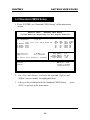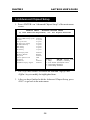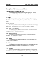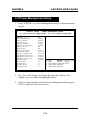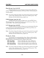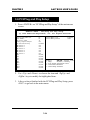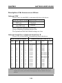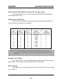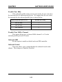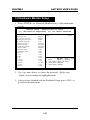
1
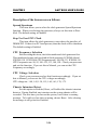
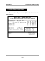
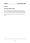
CHAPTER 3 AMI® BIOS USERS GUIDE Chapter 3 AMI® BIOS USER’S GUIDE The system configuration information and chipset register information is stored in the CMOS RAM. This information is retained by a battery when the power is off. Enter the BIOS setup (if needed) to modify this information. The following pages will describe how to enter BIOS setup, and all about options. 3-1 CHAPTER 3 AMI® BIOS USERS GUIDE 3.1 Enter BIOS Setup Enter the AMI® setup Program’s Main Menu as follows: 1. Turn on or reboot the system. The following screen appears with a series of diagnostic check. AMIBIOS (C) 1999 American Megatrends Inc. A6195 VXXX XXXXXX Hit <DEL> if you want to run setup (C) American Megatrends Inc. 61-XXXX-001169-00111111-071592-i82440FX-H 2. When the “Hit <DEL>” message appears, press <DEL> key to enter the BIOS setup screen. 3. After pressing <DEL> key, the BIOS setup screen will appear. Note: If you don’t want to modify CMOS original setting, then don’t press any key during the system boot. 3-2 CHAPTER 3 AMI® BIOS USERS GUIDE AMIBIOS SIMPLE SETUP UTILITIES - VERSION 1.21a (C) 1999 American Megatrends, Inc. All Rights Reserved Standard CMOS Setup Peripheral Setup Advanced CMOS Setup Hardware Monitor Setup Advanced Chipset Setup Change Supervisor Password Power Management Setup Change User Password PCI/Plug and Play Setup Auto-Detect Hard Disks Load Fail Safe Settings Save Settings and Exit Load Optimal Settings Exit Without Saving Esc :Quit F5 :Old Values ↑↓→← : Select Item F7 :Load Setup Defaults (Shift)F2: Change Color F10 : Save & Exit Standard CMOS Setup for changing time, date , hard disk, etc. 4. Use the <Up> and <Down> key to move the highlight scroll up or down. 5. Use the <ENTER> key to select the option. 6. To exit, press <ESC>. To save and exit, press <F10>. 7. Section 3.2 to 3.7 will explain the option in more details. 3-3 CHAPTER 3 AMI® BIOS USERS GUIDE 3.2 Standard CMOS Setup 1. Press <ENTER> on “Standard CMOS Setup” of the main menu screen . AMIBIOS SETUP - STANDARD CMOS SETUP (C)1999 American Megatrends,Inc.All Rights Reserved Date (mm/dd/yyyy): Time (hh/mm/ss): Pri Pri Sec Sec Master Slave Master Slave Type :Auto :Auto :Auto :Auto Fri Oct 29, 1999 17:09:25 Size Floppy Drive A: Floppy Drive B: Cyln Head WPcom Sec 1.44 MB 3 1/2 Not Installed Boot Sector Virus Protection Disabled Available Options: Disabled Enabled LBA Mode ON ON ON ON Blk Mode ON ON ON ON PIO Mode AUTO AUTO AUTO AUTO 32Bit Mode ON ON ON ON Base Memory : 0 Kb Other Memory : 384 Kb Extended Memory : 0 Mb Total Memory : 1 Mb ESC:Exit ↑↓:Select Item ↑↓ PU/PD/+/-:Modify (Shift)F2:Color 2. Use <Up> and <Down> to choose the item and <PgUp> and <PgDn> keys to modify the highlighted item. 3. After you have finished with the Standard CMOS Setup, <ESC> to go back to the main menu. 3-4 press CHAPTER 3 AMI® BIOS USERS GUIDE 3.3 Advanced CMOS Setup 1. Press <ENTER> on “Advanced CMOS Setup” of the main menu AMIBIOS SETUP - ADVANCED CMOS SETUP (C) 1999 American Megatrends, Inc. All Rights Reserved Quick Boot Disabled External Cache WriteBack L2 Cache ECC TableDefault 1st Boot Device Floppy System BIOS Cacheable Disabled 2nd Boot Device CD-ROM C000, 32k Shadow Disabled 3rd Boot Device IDE0 C800, 16K Shadow Disabled 4th Bood Device Disabled CC00, 16K Shadow Disabled Try Other Boot Devices Yes D000, 16K Shadow Disabled D400, 16K Shadow Disabled Initial Display Mode BIOS D800, 16K Shadow Disabled Add-On ROM Init Force-BIOS DC00, 16K Shadow Disabled Hard Disk Access Control Read-Write S.M.A.R.T. For Hard Disk Enabled BootUp Num-Lock On Floppy Drive Swap Disabled Floppy Drive Seek Enabled PS/2 Mouse Support Enabled Primary Display VGA/EGA Password Check Setup Boot to OS/2 > 64M No Internal Cache WriteBack ESC:Exit ↑ ↓ → ← :Select Item F1 :Help PU/PD/+/-:Modify F5 :Old Values (Shift)F2:Color F6 :Load BIOS Defaults F7 :Load Setup Defauls 2. Use <Up> and <Down> to choose the item and <PgUp> and <PgDn> keys to modify the highlighted item. 3. After you have finished with the Advanced CMOS Setup, press <ESC> to go back to the main menu. 3-5 CHAPTER 3 AMI® BIOS USERS GUIDE Description of the item on screen follows: Quick Boot Set this option to Enabled to permit AMI® BIOS to boot within 5 seconds. This option replaces the old ABOVE 1 MB Memory Test option. The Optimal default setting is Enabled. The Fail-Safe default setting is Disabled. 1st Boot Device/2nd Boot Device/3rd Boot Device/4th Bood Device This option sets the sequence of boot drives. The settings are: IDE0 The system will boot from the first HDD. IDE1 The system will boot from the Second HDD. IDE2 The system will boot from the Third HDD. IDE3 The system will boot from the Fourth HDD. F(optical) The system will boot from LS-120(120M Floppy). SCSI The system will boot from the SCSI. Network The system will boot from the Network drive. CD-ROM The system will boot from the CD-ROM. Disable Disable this sequence. Try other Boot Devices This option sets the device boot, if all the Four Boot Devices failed. Initial Display Mode This option sets the device boot, if all the Four Boot Devices failed. Add-On ROM Init This option sets the device boot, if all the Four Boot Devices failed. Hard Disk Access Control This option sets the Hard Disk to Read-only or Read-Write. During Read-Only, if you try to write on the Hard Disk, the system will halt. 3-6 CHAPTER 3 AMI® BIOS USERS GUIDE S.M.A.R.T. for Hard Disks This option sets the SMART Function for the hard disk. The hard disk need to have SMART function for this feature to work. Boot up Num Lock When this option is set to Off, AMI® BIOS turns off the Num Lock key when the system is powered on. The end user can then use the arrow keys on both the numeric keypad and the keyboard. The settings are On or Off. The optimal default and Fail-Safe default settings are On. Floppy Drive Swap Set this option to Enabled to specify that floppy drives A: and B: are swapped. The setting are Enabled and Disabled. The Optimal and Fail-Safe default settings are Disabled. Floppy Drive Seek When this option is set to Enabled, AMI® BIOS performs a Seek command on floppy drive A: before booting the system. The settings are Enabled and Disabled. The Optimal and Fail-Safe default settings are Disabled. PS/2® Mouse Support When this option is set to Enabled, AMI® BIOS supports a PS/2® mouse. The settings are Enabled and Disabled. The Optimal and Fail-Safe default settings are Enabled. Primary Display This option configures the primary display subsytem in the computer. The settings are Mono(monochrome), 40CGA, 80CGA or VGA/EGA. The optimal and Fail-Safe default settings are VGA/EGA. Password Check This option specifies the type of AMI® BIOS password protection that is implemented. The Optimal and Fail-Safe default settings are Setup. 3-7 CHAPTER 3 AMI® BIOS USERS GUIDE Boot To OS/2® > 64MB Set this option to Enabled to permit the BIOS to run properly, if OS/ 2® is to be used with > 64MB of DRAM. The settings are Enabled or Disabled. The Optimal and Fail-safe default settings are Disabled. Internal Cache This option Enabled or Disabled the Internal Cache. External Cache This option Enabled or Disabled the External Cache. L2 CacheECC This option enables the Level 2 Cache memory ECC(Error Check Correction). System BIOS Cacheable AMI® BIOS always copies the system BIOS from ROM to RAM for faster execution. Set this option to Enabled to permit the contents of the F0000h RAM memory segment to be written to and read from cache memory. The settings are Enabled or Disabled. The Optimal default setting is Disabled. The Fail-Safe default setting is Disabled. C000, 32K Shadow These options specify how the contents of the video ROM are handled. The settings are: Disabled - the Video ROM is not copied to RAM. Cached - the contents of the video ROM from C0000h - C7FFFh are not only copied from ROM to RAM; it can also be written to or read from cache memory. Shadow - the Contents of the video ROM from C0000h - C7FFFh are copied(shadowed) from ROM to RAM for faster execution. The Optimal and Fail-Safe default setting is Disabled. 3-8 CHAPTER 3 AMI® BIOS USERS GUIDE 3.4 Advanced Chipset Setup 1. Press <ENTER> on “Advanced Chipset Setup” of the main menu screen. AMIBIOS SETUP - ADVANCED CHIPSET SETUP (C) 1999 American Megatrends, Inc. All Rights Reserved ******** SDRAM Timing ******** Configure SDRAM Timing by SPD Disabled PH Limit 32 Cycles Idle Cycle Limit 8 Cycles TRC Bank Cycle Timing 8 Cycles TRP SRAS Precharge 3 Cycles TRAS Timing 5 Cycles TRCD Timing 2 Cycles CAS Latency 3 Cycles DRAM Integrity Mode Disabled DRAM Burst Refresh Enabled Memory Hole Disabled Graphics Aperture Size 32MB MDA Support No USB Function Disabled USB KB/Mouse Legacy Support Disabled ESC:Exit ↑ ↓ → ← :Select Item F1 :Help PU/PD/+/-:Modify F5 :Old Values (Shift)F2:Color F6 :Load BIOS Defaults F7 :Load Setup Defauls 2. Use <Up> and <Down> to choose the item and <PgUp> and <PgDn> keys to modify the highlighted item. 3. After you have finished with the Advanced Chipset Setup, press <ESC> to go back to the main menu. 3-9 CHAPTER 3 AMI® BIOS USERS GUIDE Description of the item on screen follows: Configure SDRAM Timing By SPD Choose Enabled, will automatically configure the DRAM Timing depending on the “DRAM Speed” selection. Choose Disabled, to customize the setup. PH Limit This item specify the number of consecutive Page-Hit requests to allow before choosing a non Page-Hit request. The settings are: 1/4/32/64 cycles. Idle Cycle Limit This item specify the number of idel cycles to wait before precharging an idle bank. The settings are: 0/8/12/16/24/32/48 cycles or disabled. TRC Bank Cycle Timing This item specify the minimum time to activate the same bank. The settings are: 3/4/5/6/7/8 cycles or reserved. TRP SRAS Precharge This item specify the delay from precharge command to activate command. The settings are 2/3 cycles. Tras Timing This item specify the minimum bank active time. The settings are: 2/ 3/4/5/6/7 cycles or reserved. Trcd Timing This item specify the delay from activation of a bank to the time that a read or write command is accepted. The settings are: 1/2/3/4 cycles. CAS Latency When synchronous DRAM is installed, the number of clock cycles of CAS Latency depends on the DRAM timing. The settings are: 2/3 cycles. 3-10 CHAPTER 3 AMI® BIOS USERS GUIDE DRAM Integrity Mode Set this option to Enabled or Disabled the DRAM integrity mode. The Optional and Fail-Safe default settings are Disabled. DRAM Burst Refresh Set this option to Enabled or Disabled the DRAM burst refresh. Memory Hole This option allows the end user to specify the location of a memory hole. The cycle matching the selected memory hole will be passed to the ISA bus. If Enabled, the selected hole is not remapped. Graphics Aperture Size This option determines the effective size of the graphics aperture used in the particular PAC configuration. The AGP aperture is memorymapped, while graphics data structure can reside in a graphics aperture. The aperture range should be programmed as not cacheable in the processor cache, accesses with the aperture range are forwarded to the main memory, then PAC will translate the original issued address via a translation table that is maintained on the main memory. The option allows the selection of an aperture size of 4MB, 8MB, 16MB, 32MB, 64MB, 128MB, and 256MB. MDA Support This option determines whether the VGA card can support the monochrome. During Enabled, the VGA can support monochrome. The default setting is Disabled. USB Function Set this option to Enabled or Disabled the on-chip USB controller. The Optional and Fail-Safe default settings are Enabled. USB KB/Mouse Legacy Support Set this option to Enabled or Disabled USB Mouse & keyboard. The Optional and Fail-Safe default settings are Disabled. 3-11 CHAPTER 3 AMI® BIOS USERS GUIDE 3.5 Power Management Setup 1. Press <ENTER> on “Power Management Setup” of the main menu screen. AMIBIOS SETUP - POWER MANAGEMENT SETUP (C) 1999 American Megatrends, Inc. All Rights Reserved ACPI Aware O/S Yes Power Management/APM Enabled Video Off Method Suspend Video Off After Suspend HDD power Down Mode Suspend Suspend Time Out (Minute) Disabled Modem Use IO Port N/A Modem Use IRQ N/A Power Button Function On/Off Green PC LED Status Dual Color Restore on AC/Power Loss Power Off Ring Resume from Soft Off Disabled PME# Resume from Soft Off Disabled LAN Resume from Soft Off Disabled Resume By Alarm Disabled RTC Alarm Date 15 RTC Alarm Hour 12 RTC ALarm Minute 30 RTC Alarm Second 30 ESC:Exit ↑ ↓ → ← :Select Item F1 :Help PU/PD/+/-:Modify F5 :Old Values (Shift)F2:Color F6 :Load BIOS Defaults F7 :Load Setup Defauls 2. Use <Up> and <Down> to choose the item and <PgUp> and <PgDn> keys to modify the highlighted item. 3. After you have finished with the Power Management Setup, press <ESC> to go back to the main menu. 3-12 CHAPTER 3 AMI® BIOS USERS GUIDE Description of the item on screen follows: ACPI Aware O/S This option sets the ACPI Power Management to be active or not. The settings are yes or no. Power Management/APM Set this option to enable the chipset’s power management features and APM(Advanced Power Management). The settings are Enabled, InstOn(instant-on) or Disabled. The Optimal default settings are Enabled. The Fail-Safe Default is Disabled Video Off Method This determines the manner in which the monitor is blanked. V/H SYNC+Blank This selection will cause the system to turn off the vertical and horizontal synchronization ports and write blanks to the video buffer. Blank Screen This option only writes blanks to the video buffer. DPMS (default) Initial display power management signaling. Video Off After This option specifies the power conserving state that the VESA VGA video subsystem enters after the specified period of display inactivity has expired. The settings are Disabled, Standby or Suspend. The Optimal and Fail-Safe default settings are Suspend. HDD Power Down Mode This option specifies the power conserving state that the hard disk drive enters after the specified period of hard drive inactivity has expired. The settings are Disabled, Standby or Suspend. The Optimal and Fail-Safe default settings are Suspend. 3-13 CHAPTER 3 AMI® BIOS USERS GUIDE Suspend Time Out (Minute) This option specifies the length of a period of system inactivity while in Suspend state. When this length of time expires, the computer enters Suspend power state. The settings are Disabled, 1 min, 2 min, 4 min, 8 min, 10 min, 20 min, 30 min, 40 min, 50 min or 60 min. The Optimal and Fail-Safe default settings are Disabled. Modem Use IO Port This indicates which I/O port will be used by the Modem (if there is a modem installed) Modem Use IRQ This indicates which IRQ number will be used by the Modem (if there is a modem installed). Power Button Function During Suspend, if you push the switch once, the system goes into suspend mode and if you push it more than 4 seconds, the system will be turned off. During On/Off, the system will turn off once you push the switch. Green PC LED Status This item determines which state the Power LED will use. The settings are Blinking, Dual, and Single. During blinking, the power LED will blink when the system enters the suspend mode. When the mode is in Dual, the power LED will change its color. Choose the single and the power LED will always remain lit. Restore on AC/Power Loss The settings are power on, power off or last state. During power on, after every AC power loss, the system will be turned on. During last status, after every AC power losss, whatever the system status, it will be the same when the AC power returns. 3-14 CHAPTER 3 AMI® BIOS USERS GUIDE Ring Resume from Soft-Off During Disabled, the system will ignore any incoming call from the modem. During Enabled, the system will boot up if there’s an incoming call from the modem. Note: If you have change the setting, you must let the system boot up until it goes to the operating system. Then, power off the system. This function will work the next time you power on. PME# Resume from Soft Off During Disabled, the system will ignore any event on PME (Power Management Event). During Enabled, the system wull boot up if there’s an event on PME. The default setting is Disabled. LAN Resume from Soft-Off During Disabled, the system will ignore any incoming signal from the LAN network card. During Enabled, the system will boot up if there’s an incoming signal from the LAN network card. Note: If you have change the setting, you must let the system boot up until it goes to the operating system. Then, power off the system. This function will work the next time you power on. Resume by Alarm This function is for setting the Date, Hour, Minute, and Second for your computer to boot up. During Disabled, you cannot use this function. During Enabled, Choose the Date, Hour, Minute, and Second: RTC Alarm Date Choose which day the system will boot up. RTC Alarm Hour Choose which hour the system will boot up. RTC Alarm Minute Choose which minute the system will boot up. RTC Alarm Second Choose which second the system will boot up. Note: If you have change the setting, you must let the system boot up until it goes to the operating system. Then, power off the system. This function will work the next time you power on. 3-15 CHAPTER 3 AMI® BIOS USERS GUIDE 3.6 PCI/Plug and Play Setup 1. Press <ENTER> on “PCI/Plug and Play Setup” of the main menu screen. AMIBIOS SETUP - PCI/Plug and Play Setup (C) 1999 American Megatrends, Inc. All Rights Reserved Plug and Play Aware O/S No Reserved Memory Size Disabled Clear NVRAM No Reserved Memory Address C8000 PCI Latency Timer 32 Primary Graphics Adapter PCI PCI VGA Palette Snoop Disabled DMA Channel 0 PnP DMA Channel 1 PnP DMA Channel 3 PnP DMA Channel 5 PnP DMA Channel 6 PnP DMA Channel 7 PnP IRQ3 PCI/PnP IRQ4 PCI/PnP IRQ5 PCI/PnP IRQ7 PCI/PnP IRQ9 PCI/PnP IRQ10 PCI/PnP IRQ11 PCI/PnP IRQ14 PCI/PnP IRQ15 PCI/PnP ESC:Exit ↑ ↓ → ← :Select Item F1 :Help PU/PD/+/-:Modify F5 :Old Values (Shift)F2:Color F6 :Load BIOS Defaults F7 :Load Setup Defauls 2. Use <Up> and <Down> to choose the item and <PgUp> and <PgDn> keys to modify the highlighted item. 3. After you have finished with the PCI/Plug and Play Setup, press <ESC> to go back to the main menu. 3-16 CHAPTER 3 AMI® BIOS USERS GUIDE Description of the item on screen follows: Plug and Play Aware O/S Set this option to Yes if the operating system in this computer is aware of and follows the Plug and Play specification. Currently, only Windows® 95 is PnP-aware. The settings are Yes or No. The Optimal and Fail-Safe default settings No. Clear NVRAM During Yes, this will clear NVRAM data on every boot. PCI Latency Timer This option specifies the latency timings (in PCI clocks) for all PCI devices on the PCI bus. The settings are 32, 64, 96, 128, 160, 192, 224 or 248. The Optimal and Fail-Safe default settings are 64. Primary Graphics Adapter This option is for selecting which VGA card is to be your primary display graphics adapter. PCI VGA Palette Snoop When this option is set to Enabled, multiple VGA devices operating on different buses can handle data from the CPU on each set of palette registers on every video device. Bit 5 of the command register in the PCI device configuration space is the VGA Palette Snoop bit (0 is disabled). For example, if there are two VGA devices in the computer (one PCI and ISA) and the Bit settings are: Disabled - Data read and written by the CPU is only directed to the PCI VGA device’s palette registers. Enabled - Data read and written by the CPU is directed to both the PCI VGA device’s palette registers and the ISA VGA device palette registers, permitting the palette registers of both devices to be identical. This option must be set to Enabled if an ISA adapter card requires VGA palette snooping. The settings are Enabled or Disabled. The Optimal and Fail-Safe default settings are Disabled. 3-17 CHAPTER 3 AMI® BIOS USERS GUIDE DMA Channel 0/1/3/5/6/7 These options specify the bus that the specified DMA channel is used. These options allow you to reserve DMAs for legacy ISA adapter cards. These options determine if AMI® BIOS should remove a DMA from the available DMAs passed to devices that are configurable by the system BIOS. The available DMA pool is determined by reading the ESCD NVRAM. If more DMAs must be removed from the pool, the end user can use these options to reserve the DMA by assigning an ISA/EISA setting to it. IRQ3/IRQ4/IRQ5/RQ7/IRQ9/IRQ10/IRQ11/IRQ14/IRQ15 These options specify the bus that the specified IRQ line is used on. These options allow you to reserve IRQs for legacy ISA adapter cards. These options determine if AMI® BIOS should remove an IRQ from the pool of available IRQs passed to devices that are configurable by the system BIOS. The available IRQ pool is determined by reading the ESCD NVRAM. If more IRQs must be removed from the pool, the end user can use these options to reserve the IRQ by assigning an ISA/EISA setting to it. Onboard I/O is configured by AMI® BIOS. All IRQs used by onboard I/O are configured as PCI/PnP. If all IRQs are set to ISA/EISA and IRQ14 and 15 are allocated to the onboard PCI IDE, IRQ9 will still be available for PCI and PnP devices, because at least one IRQ must be available for PCI and PnP devices. The settings are ISA/EISA or PCI/PnP. The Optimal and Fail-Safe default settings are PCI/PnP. Reserved Memory Size This option allows the user to reserved the memory size for old addon card. The settings are 16k/23k/64k/Disabled. Reserved Memory Address This option allows the user to reserved the memory size of the old add-on card in the reserved memory address. The default setting is C8000. 3-18 CHAPTER 3 AMI® BIOS USERS GUIDE 3.7 Peripheral Setup 1. Press <ENTER> on “Peripheral Setup” of the main menu screen. AMIBIOS SETUP - Peripheral SETUP (C) 1999 American Megatrends, Inc. All Rights Reserved Onboard FDC Auto Onboard Serial Port A Auto Onboard Serial Port B Auto Serial Port B Mode Normal IrDA Protocol N/A Ir I/O pin Select IRRX/IRTX Onboard Parallel Port Auto Parallel Port Mode ECP EPP Version N/A Parallel Port IRQ Auto Parallel Port DMA Channel Auto Onboard IDE Both Onboard Sound Enabled ESC:Exit ↑ ↓ → ← :Select Item F1 :Help PU/PD/+/-:Modify F5 :Old Values (Shift)F2:Color F6 :Load BIOS Defaults F7 :Load Setup Defauls 2. Use <up> and <down> to choose the item and <PgUp> and <PgDn> keys to modify the highlighted item. 3. After you have finished with the Peripheral Setup, press <ESC> to go back to the main menu. 3-19 CHAPTER 3 AMI® BIOS USERS GUIDE Description of the item on screen follows: Onboard FDC Choose Auto, for the BIOS to automatically detect the device If the ISA add-on card has Onboard FDC to be set at FDC exist Disabled none FDC exist Enabled Choose Enabled, Enabling onboard FDC. Choose Disabled, Disabling onboard FDC. The Optimal and Fail-Safe default settings are Auto. Onboard Serial Port A/Onboard Serial Port B Choose 3F8, for the BIOS to automatically detect the device. If the ISA add-on card has COM4 COM3 COM2 COM1 (I/O:3F8H) (I/O:3F8H) (I/O:3E8H) (I/O:2E8H) ü ü X ü X ü ü ü X X ü X X X ü ü X X ü ü ü X ü X X ü X X ü X ü X ü ü X ü ü X X X ü X ü X ü ü X X ü ü ü X X X X ü Onboard Serial port to be set at PORT1 DISABLED COM3 COM1 COM2 COM1 COM4 COM3 COM2 COM1 COM1 COM2 COM1 COM1 COM1 IRQ ASSIGNED X 4 4 3 4 3 4 3 4 4 3 4 4 4 PORT2 DISABLED COM4 COM2 COM3 COM4 DISABLED DISABLED DISABLED DISABLED COM2 COM3 COM3 COM2 COM2 IRQ ASSIGNED X 3 3 4 3 X X X X 3 4 4 3 3 Note: If the onboard serial port interrupt and ISA add-on card interrupt are in conflict, the serial port will not work properly. Please disable one of the devices. 3-20 CHAPTER 3 AMI® BIOS USERS GUIDE Serial PortB Mode/IrDA Protocol/Ir I/O pin Select This items allows the user to determine which InfraRed (IR) function of the onboard I/O chip. Onboard Parallel Port Choose Auto, the BIOS automatically assigned onboard parallel port to the available parallel port or disabled. If the ISA add-on card has Onboard parallel port to be set as LPT1 LPT2 LPT3 I/O:378H I/O:278H I/O:3BCH ü ü ü ü ü X ü X ü X ü ü ü X X X ü X X X ü X X X PORT ASSIGNED Disabled LPT3 LPT2 LPT1 LPT2 LPT1 LPT1 LPT1 IRQ ASSIGNED X 5 5 7 5 7 7 7 Note: If the onboard parallel port interrupt and ISA add-on card interrupt are in conflict, the parallel port will not work properly. Please disable one of the devices. Parallel Port Mode This option allows user to choose the operating mode of the onbaord parallel port. The settings are Normal, SPP/EPP or ECP mode. EPP Version This option is for setting which EPP version will be used. The settings are 1.7 and 1.9. 3-21 CHAPTER 3 AMI® BIOS USERS GUIDE Parallel Port IRQ If the onboard parallel mode is not on auto mode, the user can select the interrupt line for onboard parallel port. We suggest that the user select the interrupt for the onboard parallel port as shown below: Parallel Port IRQ Onboard parallel port set at LPT1(378H) 7 LPT2(278H) 5 LPT3(3BCH) 5 Parallel Port DMA Channel This option allows user to choose DMA channel 1 to 3 for the onboard parallel port on ECP mode. Onboard IDE Set this option to enable or disable on board IDE controller. Onboard Sound This item allows you to enable/disable the onboard Aureal audio chipset. The settings are Enabled, Disabled. 3-22 CHAPTER 3 AMI® BIOS USERS GUIDE 3.8 Hardware Monitor Setup 1. Press <ENTER> on “Hardware Monitor Setup” of the main menu screen. AMIBIOS SETUP - Hardware Monitor Setup (C) 1999 American Megatrends, Inc. All Rights Reserved -= Hardware Monitor =- +5VSB Spread Spectrum Enabled Stop Un-used PCI Clock Enabled CPU Frequency Selection 100MHz CPU Voltage Selection 1.60V Chassis Intrusion Disabled CPU Temperature 350C/950F System Temperature 330C/910F CPU Fan Speed 6683RPM Power Fan Speed 0 RPM System Fan Speed 0 RPM CPU VID 1.60V Vcore 1.616V Vsram 3.312V 3.3V 3.360V +5.000V 5.08V +12.000V 11.851 -12.000V -12.646V -5.000V -5.127 Battery 3.025V 5.028V ESC:Exit ↑ ↓ → ← :Select Item F1 :Help PU/PD/+/-:Modify F5 :Old Values (Shift)F2:Color F6 :Load BIOS Defaults F7 :Load Setup Defauls 2. Use <up> and <down> to choose the item and <PgUp> and <PgDn> keys to modify the highlighted item. 3. After you have finished with the Peripheral Setup, press <ESC> to go back to the main menu. 3-23 CHAPTER 3 AMI® BIOS USERS GUIDE Description of the item on screen follows: Spread Spectrum This item allows you to select the clock generator Spread Spectrum function. When overclocking the processor, always set this item to Disabled. The defualt setting is Enabled. Stop Un-Used PCI Clock This item allows the clock generator to auto-detect the interface of DIMM/PCI. If there’s no PCI card present, then the clock will be shutdown. The default setting is Enabled. CPU Frequency Selection Before setting this item, check the mainboard clock generator first. This mainboard comes with two kind of clock generator: ICS9248-64 and ICS9248-110. ICS9248-64 CPU Frequencies are: 100,120,133. ICS9248-110 CPU Frequencies are: 90, 95, 100~125, 133, 140, 150.. Check your processor and set this function. If you set this to Manual, you can set the CPU Frequency accordingly. CPU Voltage Selection Check your processor and set this function accordingly. If you set this to Manual, you can set the CPU voltage accordingly. CPU voltage are: 1.40, 1.45, 1.50, 1.55, 1.60, 1.65, 1.70, 1.75. Chassis Intrusion Detect Set this option to Enabled, Reset, or Disabled the chassis intrusion detector. During Enabled, any intrusion on the system chassis will be recorded. The next time you turn on the system, it will show a warning message. To be able to clear those warning, choose Reset. After clearing the message it will go back to Enabled. 3-24 CHAPTER 3 AMI® BIOS USERS GUIDE 3.9 Auto-Detect Hard Disks You can use this utility to automatically detect the characteristics of most hard drives. AMIBIOS SETUP - STANDARD CMOS SETUP (C)1999 American Megatrends,Inc.All Rights Reserved Date (mm/dd/yyyy): Time (hh/mm/ss): Pri Pri Sec Sec Master Slave Master Slave Type :Auto :Auto :Auto :Auto Fri Oct 29, 1999 17:09:25 Size Floppy Drive A: Floppy Drive B: Cyln Head WPcom Sec 1.44 MB 3 1/2 Not Installed Boot Sector Virus Protection Disabled Available Options: Disabled Enabled LBA Mode ON ON ON ON Blk Mode ON ON ON ON PIO Mode AUTO AUTO AUTO AUTO 32Bit Mode ON ON ON ON Base Memory : 0 Kb Other Memory : 384 Kb Extended Memory : 0 Mb Total Memory : 1 Mb ESC:Exit ↑↓:Select Item ↑↓ PU/PD/+/-:Modify (Shift)F2:Color 3-25 CHAPTER 3 AMI® BIOS USERS GUIDE 3.10 Change User/Supervisor Password This Main Menu item lets you configure the system so that a password is required each time the system boots or an attempt is made to enter the Setup program. Supervisor Password allows you to change all CMOS settings but the User Password setting doesn’t have this function. The way to set up the passwords for both Supervisor and User are as follow: 1. Choose “Change Password” in the Main Menu and press <Enter>. The following message appears: “Enter Password:” 2. The first time you run this option, enter your password up to 6 characters only and press <Enter>. The screen will not display the entered characters. For no password, just press <Enter>. 3. After you enter the password, the following message appears prompting you to confirm the password: “Retype Password:” 4. Enter exactly the same password you just typed in to confirm the password and press <Enter>. 5. Move the cursor to Save Settings and Exit to save the password. 6. If you need to delete the password you entered before, choose the Supervisor Password and press <Enter>. It will delete the password that you had before. 7. Move the cursor to Save Settings and Exit to save the option you did. Otherwise, the old password will still be there when you turn on your machine next time. 3-26