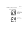
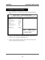
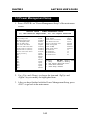
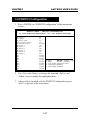
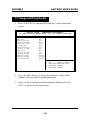
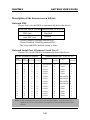
1
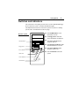
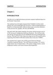
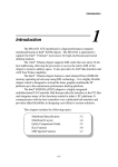
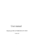
PC0027 mech 4/12/2000 4:55 PM Page 3 Apollo/Shadowhawk Apollo/Shadowhawk 440S Series User’s Manual u s e r m a n u a l System Manual ii Premio System Manual Copyright Premio is a registered trademark of Premio Computer, Inc. All other brands and product names are trademarks or registered trademarks of their respective companies. © 1997 by Premio Computer, Inc. All rights reserved. Printed in Taiwan. Apollo/Shadowhawk, May 2000. Disclaimers Premio makes no representation or warranties, either expressed or implied, with respect to the contents of this publication and specifically disclaims the implied warranties of merchantability or fitness for a particular purpose. Premio shall not be liable for technical or editorial errors or omissions in this publication, or for incidental or consequential damages resulting from the furnishing, performance, or use of this publication. We reserve the right to revise this publication and to make changes from time to time in its contents without notification. Getting Started iii Contents GETTING STARTED .............................................................. 1 Setting Up ...................................................................................... 2 Switches and Indicators............................................................... 3 UPGRADING .......................................................................... 5 Opening the System Unit ............................................................. 6 Installing an Expansion Card....................................................... 7 Installing a Hard Drive .................................................................. 8 GETTING HELP ..................................................................... 9 Troubleshooting............................................................................ 9 Monitor Does Not Work...................................................... 9 Keyboard Does Not Work ................................................ 10 Mouse Does Not Work..................................................... 10 System Unit Problems ..................................................... 11 Hard Drive Problems........................................................ 11 Technical Support....................................................................... 12 Premio on the Internet ................................................................ 12 iv Premio System Manual APPENDIX............................................................................ 13 Warranty Policy ...........................................................................13 Service Under Warranty...................................................14 Exclusions from Limited Warranty Programs...................14 FCC Standards ............................................................................15 Important Safety Instructions ....................................................16 Getting Started Your Premio® system consists of three components: a mid-tower or desktop system unit a keyboard a mouse Add your choice of monitor, and your system is ready to use. System Unit Mid-tower system Keyboard Mouse Desktop system System Unit Keyboard Mouse 2 Premio System Manual Setting Up To set up your Premio system, simply connect your monitor, the mouse, the keyboard, and any additional components you want to use to the system unit. Follow these easy steps: Power Connector Mouse Connector Keyboard Connector USB Connector Serial-1 Connector Serial-2 Connector Parallel Connector Video Connector Sound Card Connectors 1 Attach your monitor’s video cable to the video connector. 2 Attach the mouse cable to the mouse connector. 3 Attach the keyboard cable to the keyboard connector. 4 Attach the cables for any additional components, such as a printer, scanner, or modem, to the respective parallel, serial, or universal serial bus (USB) connector, as directed in the component’s manual. 5 If your system is equipped for multimedia, attach your speakers and microphone to the sound card connectors. 6 Plug your monitor’s power cord into a power outlet. 7 Attach the female end of the system power cord to the system unit’s power connector, and then plug the other end of the cord into a power outlet. Your Premio system is now ready to use. To start the system, turn on your monitor’s power switch, and then press the system power switch as shown on the next page. Getting Started 3 Switches and Indicators The system unit’s front panel provides access to the CD-ROM and floppy drives, and to the system’s switches and indicator lights. The illustration below shows a mid-tower system. If you have a desktop system, turn to the illustration on the next page. Mid-tower system The CD-ROM drive reads information on CDs. The floppy drive reads and writes information on diskettes. CD ROM Drive The power switch turns the system on and off. Floppy Drive The hard drive indicator lights when the hard drive is in use. Power Switch The power indicator lights when the system is on. Hard Drive The reset button restarts the system. Power Indicator Reset Button 4 Premio System Manual Desktop system Reset Button Hard Drive Indicator Power Indicator Power Switch CD ROM Drive Floppy Drive The reset button restarts the system. The hard drive indicator lights when the hard drive is in use. The power indicator lights when the system is on. The power switch turns the system on and off. The CD-ROM drive reads information on CDs. The floppy drive reads and writes information on diskettes. Upgrading You can upgrade your Premio system with: Expansion cards More memory An additional hard drive To install an upgrade, you must open the system unit. Before proceeding, read the important cautionary note below. Then follow the steps on the next page. Caution! Static discharge can cause permanent damage to internal electronic components of your computer. Always use the following precautions when working inside the system unit: Wear a grounding wrist strap (available at most electronics stores) when handling electronic components. Do not remove a component from its antistatic packaging until you are ready to install it. Keep one hand in contact with the metal system case. 6 Premio System Manual Opening the System Unit Note: Opening the system unit could affect your warranty. Check with the dealer where you purchased your system before opening the system unit. To open the system unit, follow these steps: Mid-tower system 1 Turn off the system and unplug the power cord. 2 Remove the screws securing the side panel (mid-tower) or case (desktop) at the rear of the system unit. Desktop system 3 Slide the side panel or case up and to the rear, and remove it. Upgrading 7 Installing an Expansion Card To install an expansion card, open the system unit as described on the previous page. Then follow these steps: 1 Remove the screw securing the slot bracket cover for the expansion slot you want to use. Save the screw to secure the expansion card. 2 Insert the expansion card firmly into the slot, making sure it is seated completely. 3 Secure the card with the saved screw. 8 Premio System Manual Installing a Hard Drive To install a hard drive in your system, follow these steps: 1 Disconnect the hard drive cable and power connector. Mid-tower system Desktop system 2 Remove the two screws securing the drive bay. 3 Slide the bay toward the rear of the system unit to remove it. 4 Insert the new drive into an open position in the bay and secure it with four screws. 5 Slide the bay back into the system unit and secure it with two screws. 6 Connect the cables. Getting Help Troubleshooting Your Premio system is designed to provide years of trouble-free performance. If you have a problem with your system, you may wish to check the information in this section for a quick solution. Monitor Does Not Work If your monitor appears not to be working properly: Check that the monitor’s power cable is securely attached to the monitor and to an outlet that is receiving power. Check that the monitor’s video cable is securely attached to the monitor and to the system unit’s video card connector. Check that the monitor’s power switch is on. Adjust the monitor’s brightness and contrast controls. If possible, substitute another monitor that is in good working order. If the substitute works, your monitor may need repair or replacement. 10 Premio System Manual Keyboard Does Not Work If the NumLock indicator in the upper right corner of the keyboard does not light when the system powers up, or the keyboard does not work: Check that the keyboard cable is securely attached to the system unit’s keyboard connector. If possible, substitute another keyboard that is in good working order. If the substitute works, your keyboard may need replacement. Mouse Does Not Work If your mouse pointer does not move or moves erratically when you move the mouse: Check that the mouse cable is securely attached to the mouse connector on the system unit. Disassemble the mouse and clean the roller ball. Getting Help 11 System Unit Problems The fan inside the system unit should make a low, steady sound when operating properly. If the fan is totally silent: Check that the system power cord is securely attached to the back of the system unit and to a power outlet. Verify that the outlet has power. If possible, substitute another power cord that is in good working order. If the substitute works, replace your power cord. If the fan makes excessive noise: Turn off the system, open the system unit case, and inspect the fan for any obstructions. Turn on the system and listen closely to the fan. If the noise comes from inside the fan housing, your power supply may need replacement. Hard Drive Problems Your hard drive should make a slight whirring sound when operating properly. If the drive is totally silent: Turn off the system, open the system unit case, and check that the power cable between the power supply and the hard drive is securely attached at both ends. If it is, your hard drive may be defective. If the hard drive makes excessive noise: Turn off the system, open the system unit case, and remove the hard drive power cable connector from the hard drive. Then turn the system back on. If the noise disappears, your hard drive may be defective. If you have more than one hard drive, repeat the same procedure for each drive. 12 Premio System Manual Technical Support You can contact Premio technical support at the following address: Premio Computer, Inc. 918 Radecki Court City of Industry, CA 91748 Telephone: 626.839.3100 Fax: 626.839.3191 Email: [email protected] Web page: http://support.premiopc.com Premio on the Internet Premio maintains a web page on the Internet with the latest information on Premio products, updated drivers, answers to common problems, a troubleshooting guide, and more. Visit our web page at: http://www.premiopc.com Appendix Warranty Policy Premio Computer, Inc. warrants its line of Premio® computer systems to be free from defects in material and workmanship for a specific warranted period as stated below, from the date of original purchase from Premio Computer, Inc. or a Premio Computer, Inc. authorized reseller. This warranty is contingent upon proper use of the product in question and does not cover products which have been modified or which have been subjected to unusual physical or electrical stress. Warranty for third party hardware and software, if any, is subject to the third party's warranty policy. Please refer to the following for length of warranty for Premio's product line. Premio Product Warranty Complete Premio System with monitor 3 years parts and labor Premio Barebone (with or without CPU) 2 years parts and labor Premio Monitor 2 year parts and labor Premio OEM Component (motherboard, speaker, case, keyboard, mouse, floppy drive, CD-ROM, etc.) 2 years parts and labor 14 Premio System Manual Service Under Warranty If this product fails to be in good working order during the warranty period (or specific period of time as noted above), Premio Computer, Inc. will, at its option, repair or replace the product. Repair parts and/or replacement products may be either new or reconditioned at Premio Computer Inc.'s discretion. The limited warranty does not include service or repair for damage from improper installation, abuse or modifications to the product not approved in writing by Premio Computer, Inc. Any service repair outside the scope of this limited warranty will be at Premio Computer, Inc.'s or its Authorized Service Provider's rates and terms in effect. This warranty is valid only within the United States, Puerto Rico, Canada, Mexico and South America. Exclusions from Limited Warranty Programs All other expressed and implied warranties for this product are hereby disclaimed. If this product is not in good working order as warranted above, Premio Computer's sole and exclusive remedy shall be repair or replacement as stated above. In no event will Premio Computer, Inc. be liable to the customer or any third party for any damages in excess of the purchase price of the product. This limitation applies to damages of any kind including any direct or indirect damages, lost profits, lost savings or other special, incidental or consequential damages. This holds true for situations even if Premio Computer, Inc. or an authorized Premio representative or dealer has been advised of the possibility of such damages or of any claim by another party. Some states do not allow the exclusion or limitation of incidental or consequential damages for some products, so the above limitation or exclusion may not apply to you. Premio Computer, Inc. authorized resellers and service providers/partners may be changed, added or deleted, without notice or liability. Premio Computer, Inc. disclaims any authorized resellers and service provider/partner to the program. This warranty gives you specific legal rights and you may also have other rights, which may vary from state to state. Appendix 15 FCC Standards This equipment has been tested and found to comply with the limits for a Class B digital device, pursuant to Part 15 of the FCC Rules. These limits are designed to provide reasonable protection against harmful interference in a residential installation. This equipment generates, uses and can radiate radio frequency energy and, if not installed and used in accordance with the instructions, may cause harmful interference to radio communications. However, there is no guarantee that interference will not occur in a particular installation. If this equipment does cause harmful interference to radio or television reception, which can be determined by turning the equipment off and on, the user is encouraged to try to correct the interference by one or more of the following measures: Reorient or relocate the receiving antenna. Increase the separation between the equipment and receiver. Connect the equipment into an outlet on a circuit different from that to which the receiver is connected. Consult the dealer or an experienced radio/TV technician for help. 16 Premio System Manual Important Safety Instructions These instructions are provided by Underwriters Laboratories, Inc. 1. Read all of these instructions and save them for later reference. 2. Follow all warnings and instructions marked on the product. 3. Unplug this product from the wall outlet before cleaning. Do not use liquid or aerosol cleaners. Use a damp cloth for cleaning. 4. Do not use this product near water. 5. Do not place this product on an unstable cart, stand or table. The product may fall, causing serious damage to the product. 6. Slots and openings on the cabinet and the back or bottom are provided for ventilation. To ensure reliable operation of the product and to protect it from overheating, do not block or cover these openings. The openings should never be blocked by placing the product on a bed, sofa, rug or other similar surface. This product should never be placed near or over a radiator or heat register. This product should not be placed in a built-in installation unless proper ventilation is provided. 7. This product should be operated from the type of power source indicated on the marking label. If you are not sure of the type of power available, consult your dealer or local power company. 8. This product is equipped with a 3-wire grounding-type plug, a plug having a third (grounding) pin. This plug will only fit into a grounding-type power outlet. This is a safety feature. If you are unable to insert the plug into the outlet, contact your electrician to replace your obsolete outlet. Do not defeat the safety purpose of the grounding-type plug. 9. Do not allow anything to rest on the power cord. Do not locate this product where the cord will be walked on. 10. If an extension cord is used with this product, make sure that the total of the ampere ratings on the products plugged into the extension cord do not exceed the extension cord ampere rating. Also, make sure that the total of all products plugged into the wall outlet does not exceed 15 amperes. 11. Never push objects of any kind into this product through cabinet slots as they may touch dangerous voltage points or short out parts Appendix 17 that could result in a risk of fire or electric shock. Never spill liquid of any kind on the product. 12. Except as explained elsewhere in this manual, don't attempt to service this product yourself. Opening and removing those covers that are marked “Do Not Remove” may expose you to dangerous voltage points or other risks. Refer all servicing on those compartments to service personnel. 13. Unplug this product from the wall outlet and refer servicing to qualified service personnel under the following conditions: A. B. C. D. E. F. When the power cord or plug is damaged or frayed. If liquid has been spilled into the product. If the product has been exposed to rain or water. If the product does not operate normally when the operating instructions are followed. Adjust only those controls that are covered by the operating instructions since improper adjustment of other controls may result in damage and will often require extensive work by a qualified technician to restore the product to normal operation. If the product has been dropped or the cabinet has been damaged. If the product exhibits a distinct change in performance, indicating a need for service. CHAPTER 1 INTRODUCTION Chapter 1 INTRODUCTION The MS-6309 ATX VA5 mainboard is a high-performance computer mainboard based on VIA® VT82C694X chipset. The MS-6309 is designed for the Intel® CeleronTM or Coppermine(FC-PGA) processor for inexpensive business/personal desktop markets. The Apollo Pro133A (VT82C694X) is a Socket-370 system logic north bridge with the addition of 133 MHz capability for both the CPU and SDRAM interfaces. Apollo Pro133A may be used to implement both desktop and notebook personal computer systems from 66MHz to 133MHz based on Socket-370 (Intel Celeron processors). The primary features of the Apollo Pro133A-North Bridge are: Slot-1 or Socket-370 CPU (Front Side Bus) Interface (66 / 100 / 133MHz), DRAM Memory Interface (66 / 100 / 133MHz), AGP Bus Interface (66MHz), PCI Bus Interface (33MHz), Mobile Power Management. The VT82C686A PSIPC (PCI Super-I/O Integrated Peripheral Controller) is a high integration, high performance, power-efficient, and high compatibility device that supports Intel and non-Intel based processor to PCI bus bridge functionality to make a complete Microsoft PC99-compliant PCI/ISA system. 1-1 CHAPTER 1 INTRODUCTION 1.1 Mainboard Features CPU l Socket 370 for Intel® CeleronTM/ Coppermine processor. l Supports 233MHz, 266MHz, 300MHz, 333MHz, 350MHz, 400MHz, 450MHz, 500MHZ, 533MHz...667MHz or faster processor. Chipset l VIA® 694X chipset. (510 BGA) - P-II FSB @133MHz - AGP 4x and PCI plus Advanced ECC Memory Controller - Support PC100/133 SDRAM, VCM technology l VIA® VT82C686A chipset. (352 BGA) - Advanced Power Management Features - Integrated Super I/O (FDC, LPT, COM 1/2, and IR) - DirectSound AC97 Audio - Dual bus Master IDE Ultra DMA33/66 - ACPI Clock Generator l 66.6 and133MHz clocks are supported. Main Memory l Support six memory banks using three 168-pin unbuffered DIMM. l Support a maximum memory size of 1.5GB (32M x 8). l Support ECC(1-bit Error Code Correct) function. l Support 3.3v SDRAM DIMM. Slots l One AGP(Accelerated Graphics Port) slot. - AGP specification compliant - AGP 66MHz 3.3v/1.5v for 2x/4x device support l One AMR (Audio Modem Riser) slot. l Five 32-bit Master PCI Bus slots and one 16-bit ISA bus slots wherein one shared slot can be used as ISA or PCI. l Supports 3.3v/5v PCI bus Interface. 1-2 CHAPTER 1 INTRODUCTION On-Board IDE l An IDE controller on the VIA® VT82C686A Chipset provides IDE HDD/ CD-ROM with PIO, Bus Master and Ultra DMA 33/66 operation modes. l Can connect up to four IDE devices. On-Board Peripherals l On-Board Peripherals include: - 1 floppy port supports 2 FDD with 360K, 720K, 1.2M, 1.44M and 2.88Mbytes. - 2 serial ports (COMA + COMB) - 1 parallel port supports SPP/EPP/ECP mode - 2 USB ports - 1 IrDA/HP connector for SIR. Audio l Chip Integrated l Creative CT5880 Hardware Audio (optional) - If Creative CT5880 Hardware audio is onboard. Then, only 4 PCI slot will be master slot. The remaining 1 slot will be slave slot. BIOS l The mainboard BIOS provides “Plug & Play” BIOS which detects the peripheral devices and expansion cards of the board automatically. l The mainboard provides a Desktop Management Interface(DMI) function which records your mainboard specifications. Dimension l ATX Form Factor : 30.5cm(L) x 19.2cm(W) x 4 layers PCB Mounting l 6 mounting holes. 1-3 CHAPTER 1 INTRODUCTION 1.2 Mainboard Layout Top: mouse Bottom: keyboard FDD IDE2 VIA 694X chipset IDE1 Bottom: COM A COM B DIMM 1 DIMM 3 Top: LPT USB2 DIMM 2 ATX Power Supply Bottom: Port 2 Socket 370 CPUFAN USB Top: Port 1 Top: Midi/ Game Port Bottom: Line-Out Line-In Mic JCD JAUX JPH AGP Slot AMR PCI SLOT 1 PCI SLOT 2 Creative CT5880 VT82C686A J4 JSPDIF PCI SLOT 3 JFSH1 BATT PCI SLOT 4 BIOS SYSFAN JMDM1 JWOL1 JBAT1 PCI SLOT 5 JRMS1 JGS1 JGL1 JFP1 ISA SLOT MS-6309 ATX VA5 Mainboard 1-4 CHAPTER 2 HARDWARE INSTALLATION Chapter 2 HARDWARE INSTALLATION 2.1 Central Processing Unit: CPU The mainboard operates with Intel® CeleronTM/Coppermine processor. The mainboard uses a CPU socket called Socket 370 for easy CPU installation. The CPU should always have a Heat Sink and a cooling fan attached to prevent overheating. 2.1-1 CPU Installation Procedures 1. Pull the lever sideways away from the socket. Then, raise the lever up to a 90-degree angle. Open Lever Sliding Plate 2. Locate Pin 1 in the socket and look for the white dot or cut edge in the CPU. Match Pin 1 with the white dot/cut edge. Then, insert the CPU. It should insert easily. Pin 1 White dot/ Cut edge CPU 3. Press the lever down to complete the installation. Close Lever CPU 2-1 Pin 1 CHAPTER 2 HARDWARE INSTALLATION 2.1-2 CPU Core Speed Derivation Procedure The BIOS can be used to set the CPU Host Bus Frequency Clock. If then CPU Clock = 66MHz Core/Bus ratio = 3.5 CPU core speed = Host Clock x Core/Bus ratio = 66MHz x 3.5 = 233MHz 2-2 CHAPTER 2 HARDWARE INSTALLATION 2.1-3 Fan Power Connectors: CPUFAN/SYSFAN These connectors support system cooling fan with + 12V. It supports three pin head connector. When connecting the wire to the connector, always take note that the red wire is the positive and should be connected to the +12V, the black wire is Ground and should be connected to GND. If your mainboard has System Hardware Monitor chipset on-board, you must use a specially designed fan with speed sensor to take advantage of this function. GND +12V SENSOR CPUFAN GND +12V SENSOR SYSFAN CPUFAN: Processor Fan SYSFAN: System Fan For fans with fan speed sensor, every rotation of the fan will send out 2 pulses. System Hardware Monitor will count and report the fan rotation speed. Note: 1. Always consult vendor for proper CPU cooling fan. 2. CPU FAN supports the FAN control. You can install PC Alert utility. This will automatically control the CPU FAN Speed according to the actual CPU temperature. 2-3 CHAPTER 2 HARDWARE INSTALLATION 2.2 Clear CMOS Jumper: JBAT1 A battery must be used to retain the mainboard configuration in CMOS RAM. Short 1-2 pins of JBAT1 to store the CMOS data. 1 3 JBAT1 1 1 2 2 3 3 Clear Data Keep Data Note: You can clear CMOS by shorting 2-3 pin, while the system is off. Then, return to 1-2 pin position. Avoid clearing the CMOS while the system is on, it will damage the mainboard. Always unplug the power cord from the wall socket. 2-4 CHAPTER 2 HARDWARE INSTALLATION 2.3 Memory Installation 2.3-1 Memory Bank Configuration The mainboard supports a maximum memory size of 1.5GB (256-bit technology) SDRAM: It provides three 168-pin unbuffered DIMMs (Double InLine Memory Module) sockets. It supports 8 MB to 512 Mbytes DIMM memory module. DIMM1(Bank0+ Bank1) DIMM2(Bank2+ Bank3) DIMM3(Bank4+ Bank5) 2-5 CHAPTER 2 HARDWARE INSTALLATION 2.3-2 Memory Installation Procedures A. How to install a DIMM Module Single Sided DIMM Double Sided DIMM 1. The DIMM slot has 2 Notch Keys “VOLT and DRAM”, so the DIMM memory module can only fit in one direction. 2. Insert the DIMM memory module vertically into the DIMM slot. Then push it in. DRAM VOLT 3. The plastic clip at the side of the DIMM slot will automatically close. 2-6 CHAPTER 2 HARDWARE INSTALLATION 2.3-3 Memory Population Rules 1. Supports only SDRAM DIMM. 2. To operate properly, at least one 168-pin DIMM module must be installed. 3. This mainboard supports Table Free memory, so memory can be installed on DIMM1 or DIMM 2 in any order. 4. Supports 3.3 volt DIMM. 5. The DRAM addressing and the size supported by the mainboard is shown below: Table 2.3-1 SDRAM Memory Addressing DRAM Tech. 16M 64M 64M DRAM DRAM Density & Addressing Width 1Mx16 ASYM 2Mx8 ASYM 2Mx32 ASYM 2Mx32 ASYM 4Mx16 ASYM 4Mx16 ASYM 8Mx8 ASYM 2Mx32 ASYM 4Mx16 ASYM 8Mx8 ASYM Address Size Row Column 11 11 11 12 11 13 13 11 12 12 8 9 9 8 10 8 9 8 8 9 2-7 MB/DIMM Single no. Double no. Side(S) pcs. Side(D) pcs. 8MBx4 16MBx8 16MBx8 32MBx16 32MBx2 64MBx4 16MBx2 32MBx4 32MB 64MB 32MB 64MB 64MB 128MB 16MB 32MB --------- CHAPTER 2 HARDWARE INSTALLATION 2.4 Case Connector: JFP1 The Keylock (reserved), Power Switch, Reset Switch, Power LED, Speaker, and HDD LED are all connected to the JFP1 connector block. Reset Switch 15 Speaker + 14 Dual Single Color Color LED LED Power LED Buzzer (short pin) + HDD LED Keylock JFP1 2-8 Power Switch CHAPTER 2 HARDWARE INSTALLATION 2.4-1 Power Switch Connect to a 2-pin push button switch. This switch has the same feature with JRMS1. 2.4-2 Reset Switch Reset switch is used to reboot the system rather than turning the power ON/ OFF. Avoid rebooting while the HDD LED is lit. You can connect the Reset switch from the system case to this pin. 2.4-3 Power LED The Power LED is lit while the system power is on. Connect the Power LED from the system case to this pin. There are two types of LED that you can use: 3-pin single color LED or 2-pin dual color LED(ACPI request). a. 3 pin single color LED connect to pin 4, 5, & 6. This LED will lit when the system is on. b. 2 pin dual color LED connect to pin 5 & 6. GREEN Color: Indicate the system is in full on mode. ORANGE Color: Indicate the system is in suspend mode. 2.4-4 Speaker Speaker from the system case is connected to this pin. If on-board Buzzer is available: Short pin 14-15: On-board Buzzer Enabled. Open pin 14-15: On-board Buzzer Disabled. 2.4-5 HDD LED HDD LED shows the activity of a hard disk drive. Avoid turning the power off while the HDD led is lit. You can connect the HDD LED from the system case to this pin. 2-9 CHAPTER 2 HARDWARE INSTALLATION 2.5 Floppy Disk Connector: FDD1 The mainboard also provides a standard floppy disk connector FDD1 that supports 360K, 720K, 1.2M, 1.44M and 2.88M floppy disk types. This connector supports the provided floppy drive ribbon cables. FDD1 1 2-10 CHAPTER 2 HARDWARE INSTALLATION 2.6 Hard Disk Connectors: IDE1 & IDE2 Primary IDE Connector Secondary IDE Connector The mainboard has a 32-bit Enhanced PCI IDE and Ultra DMA/66 (ICH)/ Ultra DMA/33 Controller that provides PIO mode 0~4, Bus Master, and Ultra DMA/33/66 function. It has two HDD connectors IDE1 (primary) and IDE2 (secondary). You can connect up to four hard disk drives, CD-ROM, 120MB Floppy (reserved for future BIOS) and other devices to IDE1 and IDE2. These connectors support the provided IDE hard disk cable. 1 1 IDE1(Primary IDE Connector) The first hard drive should always be connected to IDE1. IDE1 can connect a Master and a Slave drive. You must configure second hard drive to Slave mode by setting the jumper accordingly. IDE2(Secondary IDE Connector) IDE2 can also connect a Master and a Slave drive. 2-11 CHAPTER 2 HARDWARE INSTALLATION 2.7 Power Supply 2.7-1 ATX 20-pin Power Connector: JWR1 This connector supports the power button on-board. Using the ATX power supply, functions such as Modem Ring Wake-Up and Soft Power Off are supported by this mainboard. This power connector supports instant power on function which means that system will boot up instantly when the power connector is inserted on the board. 11 1 20 10 ATX Power Connector PIN DEFINITION PIN SIGNAL PIN SIGNAL 11 3.3V 1 3.3V 12 -12V 2 3.3V 13 GND 3 GND 14 PS_ON 4 5V 15 GND 5 GND 16 GND 6 5V 17 GND 7 GND 18 -5V 8 PW_OK 19 5V 9 5V_SB 20 5V 10 12V Warning: Since the mainboard has the instant power on function, make sure that all components are installed properly before inserting the power connector to ensure that no damage will be done. 2-12 CHAPTER 2 HARDWARE INSTALLATION 2.7-2 Remote Power On/Off Switch: JRMS1 Connect to a 2-pin push button switch. During OFF state, press once and the system turns on. During ON stage, push once and the system goes to sleep mode: pushing it more than 4 seconds will change its status from ON to OFF. If you want to change the setup, you could go to the BIOS Power Management Setup. This is only used for ATX type power supply. JRMS1 2-13 CHAPTER 2 HARDWARE INSTALLATION 2.8 IrDA Infrared Module Connector: J4 The mainboard provides one infrared (J4) connector for IR modules. This connector is for optional wireless transmitting and receiving infrared module. You must configure the setting through the BIOS setup to use the IR function. 1 VCC NC IRRX GND IRTX J4 2-14 CHAPTER 2 HARDWARE INSTALLATION 2.9 Serial Port Connectors: COM A and COM B The mainboard provides two 9-pin male DIN connectors for serial port COM A & COM B. These port are 16550A high speed communication port that send/receive 16 bytes FIFOs. You can attach a mouse or a modem cable directly into this connector. 1 234 5 678 9 COM A COM B Serial Port (9-pin Male) PIN DEFINITION PIN 1 SIGNAL DCD(Data Carry Detect) 2 SIN(Serial In or Receive Data) 3 SOUT(Serial Out or Transmit Data) 4 DTR(Data Terminal Ready) 5 GND 6 DSR(Data Set Ready) 7 RTS(Request To Send) 8 CTS(Clear To Send) 9 RI(Ring Indicate) 2-15 CHAPTER 2 HARDWARE INSTALLATION 2.10 Parallel Port Connector: LPT1 The mainboard provides a 25 pin female centronic connector for LPT. A parallel port is a standard printer port that also supports Enhanced Parallel Port (EPP) and Extended capabilities Parallel Port (ECP). See connector and pin definition below: Parallel Port (25-pin Female) LPT 1 1 13 14 25 PIN DEFINITION PIN 1 2 3 4 5 6 7 8 9 10 11 12 13 SIGNAL STROBE DATA0 DATA1 DATA2 DATA3 DATA4 DATA5 DATA6 DATA7 ACK# BUSY PE SELECT PIN 14 15 16 17 18 19 20 21 22 23 24 25 2-16 SIGNAL AUTO FEED# ERR# INIT# SLIN# GND GND GND GND GND GND GND GND CHAPTER 2 HARDWARE INSTALLATION 2.11 Mouse Connector: JKBMS1 The mainboard provides a standard PS/2® mouse mini DIN connector for attaching a PS/2® mouse. You can plug a PS/2® mouse directly into this connector. The connector location and pin definition are shown below: Pin6 NC Pin5 Mouse Clock Pin3 GND Pin4 VCC Pin1 Mouse DATA Pin2 NC PS/2 Mouse (6-pin Female) 2.12 Keyboard Connector: JKBMS1 The mainboard provides a standard PS/2® keyboard mini DIN connector for attaching a keyboard. You can plug a keyboard cable directly to this connector. Pin5 KBD Clock Pin6 NC Pin4 VCC Pin2 NC Pin1 KBD DATA Pin3 GND PS/2 Keyboard (6-pin Female) 2-17 CHAPTER 2 HARDWARE INSTALLATION 2.13 Joystick/Midi Connectors You can connect joystick or game pad to this connector. Joystick/MIDI 2.14 Audio Port Connectors Line Out is a connector for Speakers or Headphones. Line In is used for external CD player, Tape layer, or other audio devices. Mic is a connector for the microphones. Line Out Line In Mic 1/8” Stereo Audio Connectors 2-18 CHAPTER 2 HARDWARE INSTALLATION 2.15 USB Connectors The mainboard provides a UHCI (Universal Host Controller Interface) Universal Serial Bus root for attaching USB devices like: keyboard, mouse and other USB devices. You can plug the USB device directly to this connector. USB Port 2 1 2 3 4 USB Port 1 PIN 1 2 3 4 SIGNAL VCC -Data +Data GND 2-19 CHAPTER 2 HARDWARE INSTALLATION 2.16 Wake-Up on LAN Connector: JWOL1 The JWOL1 connector is for use with LAN add-on cards that supports Wake Up on LAN function. To use this function, you need to set the “Wake-Up on LAN” to enable at the BIOS Power Management Setup. 3 1 JWOL1 PIN 1 2 3 SIGNAL 5VSB GND MP_WAKEUP Note: LAN wake-up signal is active “high”. Note: To be able to use this function, you need a power supply that provide enough power for this feature. (Power supply with 750ma 5V Stand-by) 2-20 CHAPTER 2 HARDWARE INSTALLATION 2.17 Modem Wake Up Connector: JMDM1 The JMDM1 connector is for used with Modem add-on card that supports the Modem Wake Up function. 5 1 JMDM1 PIN 1 2 3 4 5 SIGNAL NC GND MDM_WAKEUP NC 5VSB Note: Modem wake-up signal is active “low”. Note: To be able to use this function, you need a power supply that provide enough power for this feature. (Power supply with 750ma 5V Stand-by) 2-21 CHAPTER 2 HARDWARE INSTALLATION 2.18 Power Saving Switch Connector: JGS1 Attach a power saving switch to JGS1. When the switch is pressed, the system immediately goes into suspend mode. Press any key and the system wakes up. JGS1 2-22 CHAPTER 2 HARDWARE INSTALLATION 2.19 Power Saving LED Connector: JGL1 JGL1 can be connected with two-color LED. There are two types of LED that you can use: 3-pin LED or 2-pin LED (ACPI request). When the 2-pin LED is connected to JGL1, the light will turn green, when system is On. During sleep mode, the 2-pin LED will change color from Green to Orange. For 3-pin LED, when LED is connected to JGL1, this will light when the system is On and blinks when it is in suspend/sleep mode. 1 + 3 JGL1 3-pin LED 2-pin LED Green Color Green Color Orange Color Orange Color 1 1 3 1-2 Single Color 1-3 Blink 3 1-2 Dual Color 2-23 CHAPTER 2 HARDWARE INSTALLATION 2.20 SPDIF Connector: JSPDIF This item is for Sony & Philips Digital Interface for AC3 decoder. 1 GND SDPIF_Out VCC 3 JSPDIF 2-24 CHAPTER 2 HARDWARE INSTALLATION 2.21 BIOS Flash Jumper: JFSH1 This jumper is used to locked/unlocked BIOS Flash. This Jumper should be unlock when flashing/programming the BIOS. JFSH1 BIOS Flash Locked BIOS Flash Unlocked 2-25 CHAPTER 2 HARDWARE INSTALLATION 2.22 AMR (Audio Modem Riser) The Audio/Modem Riser specification is an open industry-standard specification that defines a hardware scalable Original Equipmet Manufacturer (OEM) mainboard riser board and interface, which supports both audio and modem. AMR 2-26 CHAPTER 2 HARDWARE INSTALLATION 2.23 CD-In Connector: JCD This connector is for CD-ROM audio connector. R GND L JCD 2-27 CHAPTER 2 HARDWARE INSTALLATION 2.24 AUX Line In Connector: JAUX This connector is used for DVD Add on Card with Line In connector. R GND L JAUX 2-28 CHAPTER 2 HARDWARE INSTALLATION 2.25 Modem-In: JPH The connector is for Modem with internal voice connector. Mono_Out GND Phone_In JPH Mono_Out is connected to the Modem Speaker Out connector. Phone_In is connected to the Modem Microphone In connector. 2-29 CHAPTER 2 HARDWARE INSTALLATION 2.26 USB Front Connector: USB2 The mainboard provides a front Universal Serial Bus connector. This is an optional USB connector for Front Panel. 10 9 2 1 USB2 Pin 1 2 3 4 5 Description VCC GND USBD3GND USBD3+ Pin 6 7 8 9 10 2-30 Description USBD2+ GND USBD2GND VCC CHAPTER 3 AMI® BIOS USERS GUIDE Chapter 3 AMI® BIOS USER’S GUIDE The system configuration information and chipset register information is stored in the CMOS RAM. This information is retained by a battery when the power is off. Enter the BIOS setup (if needed) to modify this information. The following pages will describe how to enter BIOS setup, and all about options. 3-1 CHAPTER 3 AMI® BIOS USERS GUIDE 3.1 Enter BIOS Setup Enter the AMI® setup Program’s Main Menu as follows: 1. Turn on or reboot the system. The following screen appears with a series of diagnostic check. AMIBIOS (C) 1999 American Megatrends Inc. A6309 VXXX XXXXXX Hit <DEL> if you want to run setup (C) American Megatrends Inc. 61-XXXX-001169-00111111-071592-i82440FX-H 2. When the “Hit <DEL>” message appears, press <DEL> key to enter the BIOS setup screen. 3. After pressing <DEL> key, the BIOS setup screen will appear. Note: If you don’t want to modify CMOS original setting, then don’t press any key during the system boot. 3-2 CHAPTER 3 AMI® BIOS USERS GUIDE AMIBIOS SIMPLE SETUP UTILITIES - VERSION 1.20 (C) 1998 American Megatrends, Inc. All Rights Reserved Standard CMOS Setup Integrated Peripherals BIOS Features Setup Hardware Monitor Setup Chipset Features Setup Supervisor Password Power Management Setup User Password PNP/PCI Configuration IDE HDD Auto Detection Load BIOS Defaults Save and Exit Setup Load Setup Defaults Exit Without Saving Esc :Quit (Shift)F2: Change Color F5: Old Values ↑↓→← : Select Item F6 :Load BIOS Defaults F7 :Load Setup Defaults F10: Save & Exit Standard CMOS Setup for changing time, date , hard disk, etc. 4. Use the <Up> and <Down> key to move the highlight scroll up or down. 5. Use the <ENTER> key to select the option. 6. To exit, press <ESC>. To save and exit, press <F10>. 7. Section 3.2 to 3.7 will explain the option in more details. 3-3 CHAPTER 3 AMI® BIOS USERS GUIDE 3.2 Standard CMOS Setup 1. Press <ENTER> on “Standard CMOS Setup” of the main menu screen . AMIBIOS SETUP - STANDARD CMOS SETUP (C)1999 American Megatrends,Inc.All Rights Reserved Date (mm/dd/yyyy): Time (hh/mm/ss): Pri Pri Sec Sec Master Slave Master Slave Type :Auto :Auto :Auto :Auto Fri Oct 29, 1999 17:09:25 Size Floppy Drive A: Floppy Drive B: Cyln Head WPcom Sec 1.44 MB 3 1/2 Not Installed Boot Sector Virus Protection Disabled Available Options: Disabled Enabled LBA Mode ON ON ON ON Blk Mode ON ON ON ON PIO Mode AUTO AUTO AUTO AUTO 32Bit Mode ON ON ON ON Base Memory : 0 Kb Other Memory : 384 Kb Extended Memory : 0 Mb Total Memory : 1 Mb ESC:Exit ↑↓:Select Item ↑↓ PU/PD/+/-:Modify (Shift)F2:Color 2. Use <Up> and <Down> to choose the item and <PgUp> and <PgDn> keys to modify the highlighted item. 3. After you have finished with the Standard CMOS Setup, <ESC> to go back to the main menu. 3-4 press CHAPTER 3 AMI® BIOS USERS GUIDE 3.3 BIOS Features Setup 1. Press <ENTER> on “BIOS Features Setup” of the main menu screen. AMIBIOS SETUP - BIOS FEATURES SETUP (C) 1999 American Megatrends, Inc. All Rights Reserved DC00, 16K Shadow Quick Boot :Enabled 1st Boot Device :Floppy 2nd Boot Device :IDE-0 3rd Boot Device :CDROM S.M.A.R.T. For Hard Disk :Disabled Boot Num-Lock :On Floppy Drive Swap :Disabled Floppy Drive Seek :Disabled Password Check :Setup Boot to OS/2 > 64M :No CPU Serial Number :Enabled L2 Cache :Write Back Cache Bus ECC :Disabled System BIOS Cacheable :Enabled C000, 32k Shadow :Disabled C800, 16K Shadow :Disabled CC00, 16K Shadow :Disabled D000, 16K Shadow :Disabled D400, 16K Shadow :Disabled D800, 16K Shadow :Disabled Disabled ESC:Exit ↑ ↓ → ← :Select Item F1 :Help PU/PD/+/-:Modify F5 :Old Values (Shift)F2:Color F6 :Load BIOS Defaults F7 :Load Setup Defauls 2. Use <Up> and <Down> to choose the item and <PgUp> and <PgDn> keys to modify the highlighted item. 3. After you have finished with the BIOS Features Setup, press <ESC> to go back to the main menu. 3-5 CHAPTER 3 AMI® BIOS USERS GUIDE Description of the item on screen follows: Quick Boot Set this option to Enabled to permit AMI® BIOS to boot within 5 seconds. This option replaces the old ABOVE 1 MB Memory Test option. The Setup default setting is Enabled. The BIOS default setting is Disabled. 1st Boot Device/2nd Boot Device/3rd Boot Device This option sets the sequence of boot drives. The settings are: Disabled Disable this sequence IDE-0 The system will boot from the first HDD. IDE-1 The system will boot from the Second HDD. IDE-2 The system will boot from the Third HDD. IDE-3 The system will boot from the Fourth HDD. Floppy ZIP The system will boot from LS-120(120M Floppy). A:/LS120 Atapi ZIP C: The system will boot from the CD-ROM. CDROM SCSI The system will boot from the SCSI. Network The system will boot from the Network drive. 3-6 CHAPTER 3 AMI® BIOS USERS GUIDE S.M.A.R.T. for Hard Disks This option sets the SMART Function for the hard disk. The hard disk need to have SMART function for this feature to work. Boot up Num Lock When this option is set to Off, AMI® BIOS turns off the Num Lock key when the system is powered on. The end user can then use the arrow keys on both the numeric keypad and the keyboard. The settings are On or Off. The Setup default and BIOS default setting are On. Floppy Drive Swap Set this option to Enabled to specify that floppy drives A: and B: are swapped. The setting are Enabled and Disabled. The Setup and BIOS default settings are Disabled. Floppy Drive Seek When this option is set to Enabled, AMI® BIOS performs a Seek command on floppy drive A: before booting the system. The settings are Enabled and Disabled. The Setup and BIOS default settings are Disabled. Password Check This option specifies the type of AMI® BIOS password protection that is implemented. The Setup and BIOS default settings are Setup. 3-7 CHAPTER 3 AMI® BIOS USERS GUIDE Boot To OS/2® > 64MB Set this option to Enabled to permit the BIOS to run properly, if OS/ 2® is to be used with > 64MB of DRAM. The settings are Enabled or Disabled. The Setup and BIOS default settings are Disabled. L2 CacheECC This option enables the Level 2 Cache memory ECC(Error Check Correction). System BIOS Cacheable AMI® BIOS always copies the system BIOS from ROM to RAM for faster execution. Set this option to Enabled to permit the contents of the F0000h RAM memory segment to be written to and read from cache memory. The settings are Enabled or Disabled. The Setup default setting is Enabled. The BIOS default setting is Disabled. C000, 32K Shadow These options specify how the contents of the video ROM are handled. The settings are: Disabled - the Video ROM is not copied to RAM. Cached - the contents of the video ROM from C0000h - C7FFFh are not only copied from ROM to RAM; it can also be written to or read from cache memory. Enabled - the Contents of the video ROM from C0000h - C7FFFh are copied(shadowed) from ROM to RAM for faster execution. The Setup and BIOS default setting is Enabled. 3-8 CHAPTER 3 AMI® BIOS USERS GUIDE 3.4 Chipset Features Setup 1. Press <ENTER> on “Chipset Features Setup” of the main menu screen. AMIBIOS SETUP - CHIPSET FEATURES SETUP (C) 1999 American Megatrends, Inc. All Rights Reserved Set SDRAM Timing by SPD :Disabled DRAM Frequency :100Mhz SDRAM CAS# Latency :3 DRAM Integrity Mode :Disabled CPU In Order Queue :4-Level Memory Hole :Disabled AGP Mode :Auto AGP Comp. Driving :Auto Manual AGP Comp. Driving :CB AGP Aperture Size :64MB USB Controller :USB Port 0&1 USB KB/Mouse Legacy :Disabled ESC:Exit ↑ ↓ → ← :Select Item F1 :Help PU/PD/+/-:Modify F5 :Old Values (Shift)F2:Color F6 :Load BIOS Defaults F7 :Load Setup Defauls 2. Use <Up> and <Down> to choose the item and <PgUp> and <PgDn> keys to modify the highlighted item. 3. After you have finished with the Chipset Features Setup, press <ESC> to go back to the main menu. 3-9 CHAPTER 3 AMI® BIOS USERS GUIDE Description of the item on screen follows: Set SDRAM Timing By SPD Choose Enabled, will automatically configure the DRAM Timing depending on the “DRAM Speed” selection. Choose Disabled, to customize the setup. DRAM Frequency This item specify the DRAM frequency of the system. The settings are: 66MHz FSB Processor 66/100MHz DRAM Frequency 100MHz FSB Processor 66/100/133MHz DRAM Frequency 133MHz FSB Processor 100/133MHz DRAM Frequency SDRAM CAS# Latency When synchronous DRAM is installed, the number of clock cycles of CAS latency depends on the DRAM timing. The settings are: 2 and 3. DRAM Integrity Mode This item will automatically detect your DIMM for ECC. The Setup and BIOS default setting is Disabled. Memory Hole This option allows the end user to specify the location of a memory hole (15MB-16MB). The cycle matching the selected memory hole will be passed to the ISA bus. 3-10 CHAPTER 3 AMI® BIOS USERS GUIDE AGP Aperture Size This option determines the effective size of the graphics aperture used in the particular MCM configuration. The AGP aperture is memory mapped,wile graphics data structure can reside in a graphics aperture. The aperture range should be programmed as not cacheable in the processor cache,accesses with the aperture range are forwarded to the main memory, then MCM will translate the original issued address via a translation table that is maintained on the main memory. The option allows the selection of an aperture size of 4MB,8MB,16MB,32MB,64MB,128MB and 256MB. USB Controller Set this option to Enabled or Disabled the on-chip USB controller. The settings are USB Port 0 & 1, USB Port 2 & 3 or All USB Port. The Setting and BIOS default setting is USB Port 0 & 1. USB KB/Mouse Legacy Support Set this option to Enabled or Disabled USB Mouse & keyboard. The default setting is Disabled. 3-11 CHAPTER 3 AMI® BIOS USERS GUIDE 3.5 Power Management Setup 1. Press <ENTER> on “Power Management Setup” of the main menu screen. AMIBIOS SETUP - POWER MANAGEMENT SETUP (C) 1999 American Megatrends, Inc. All Rights Reserved Compliance With O/S :Yes IRQ15 :Ignore ACPI Standby State :S1/POS System Thermal :Ignore USB Wakeup From S3/S5 :Disabled Thermal Slow Clock Ratio :50%-56.25% Power Management/APM :Enabled Power Button Function :On/Off Green PC LED Status :Dual Color Restore on AC/Power Loss :Last State Video Power Down Mode :Suspend Resume On Ring/LAN :Enabled Hard Disk Power Down Mode :Stand-by Resume On PME# :Disabled Standby Time Out (Minute) :Disabled Resume On RTC Alarm :Disabled Suspend Time Out (Minute) :Disabled RTC Alarm Date :15 Throttle Slow Clock Ratio :50%-56.25% RTC Alarm Hour :12 Display Activity :Ignore RTC Alarm Minute :30 IRQ3 :Monitor RTC Alarm Second :30 IRQ4 :Monitor IRQ5 :Ignore IRQ7 :Monitor IRQ9 :Ignore IRQ10 :Ignore IRQ11 :Ignore IRQ13 :Ignore IRQ14 :Monitor ESC:Exit ↑ ↓ → ← :Select Item F1 :Help PU/PD/+/-:Modify F5 :Old Values (Shift)F2:Color F6 :Load BIOS Defaults F7 :Load Setup Defauls 2. Use <Up> and <Down> to choose the item and <PgUp> and <PgDn> keys to modify the highlighted item. 3. After you have finished with the Power Management Setup, press <ESC> to go back to the main menu. 3-12 CHAPTER 3 AMI® BIOS USERS GUIDE Description of the item on screen follows: Compliance With O/S Set this option to Yes the operating system is support ACPI. The setting is No, the operating system is support APM. ACPI Standby State This item will set which ACPI standby type will be used. Power Management/APM Set this option to enable the chipset’s power management features and APM(Advanced Power Management). The settings are Enabled, InstOn(instant-on) or Disabled. The Setup default setting is Enabled. The BIOS Default is Disabled Green PC Monitor Power State This option specifies the power state that the green PC-compliant video monitor enters when AMI® BIOS places it in a power savings state after the specified period of display inactivity has expired. The settings are Off, Standby, Suspend. The Setup and BIOS default setting is Standby. Video Power Down Mode This option specifies the power conserving state that the VESA VGA video subsystem enters after the specified period of display inactivity has expired. The settings are Disabled, Standby or Suspend. The default setting is Standby. Hard Disk Power Down Mode This option specifies the power conserving state that the hard disk drive enters after the specified period of hard drive inactivity has expired. The settings are Disabled, Standby or Suspend. The Setup and BIOS default setting is Standby. 3-13 CHAPTER 3 AMI® BIOS USERS GUIDE Standby TimeOut (Minute) This option defines the continuous idle time before the system enters STANDBY mode. If any item defined in the options of “Power Down and Resume events” is enabled & active, STANDBY timer will be reloaded. When the system has entered Standby mode, any of the items that are enabled in “Wake Up Events of Doze and Standby” will trigger the system to wake up. The settings are Disabled, 1 min, 2 min, 3 min, 4 min, 5 min, 6 min, 7 min, 8 min, 9 min, 10 min, 11 min, 12 min, 13 min, 14 min or 15 min. The default settings is Disabled. Suspend Time Out (Minute) This option specifies the length of a period of system inactivity while in Suspend state. When this length of time expires, the computer enters Suspend power state. The settings are Disabled, 1 min, 2 min, 4 min, 8 min, 10 min, 20 min, 30 min, 40 min, 50 min or 60 min. The default setting is Disabled. Throttle Slow Clock Ratio This option specifies the speed at which the system clock runs in power saving states. The settings are expressed as ration between the normal CPU clock speed and the CPU clock speed when the computer is in the power-conserving state. Display Activity/IRQ 3/IRQ 4/IRQ 5/IRQ 7/IRQ 9/IRQ1 0/ IRQ 11/IRQ 13/IRQ 14/IRQ 15/System Thermal When set to Monitor, these options enable event monitoring on the specified hardware interrupt request line. If set to Monitor and the computer is in a power saving state, AMI® BIOS watches for activity on the specified IRQ line. The computer enters the full on power state if any activity occurs. AMI® BIOS reloads the Standby and Suspend timeout timers if activity occurs on the specified IRQ line. Thermal Slow Clock Ratio When set to Monitor, then you can choose the throttle ratio. This option is connected with the CPU Critical Temperature Option. 3-14 CHAPTER 3 AMI® BIOS USERS GUIDE Power Button Function During Suspend, if you push the switch once, the system goes into suspend mode and if you push it more than 4 seconds, the system will be turned off. During On/Off, the system will turn off once you push the switch. Restore on AC/Power Loss The settings are power on, power off or last state. During power on, after every AC power loss, the system will be turned on. During last status, after every AC power losss, whatever the system status, it will be the same when the AC power returns. Resume On Ring/LAN During Disabled, the system will ignore any incoming call from the modem/LAN network card. During Enabled, the system will boot up if there’s an incoming call from the modem/LAN network card. Note: If you have change the setting, you must let the system boot up until it goes to the operating system. Then, power off the system. This function will work the next time you power on. Resume On PME# During Disabled, the system will ignore any event on PME (Power Management Event). During Enabled, the system wull boot up if there’s an event on PME. The default setting is Disabled. 3-15 CHAPTER 3 AMI® BIOS USERS GUIDE Resume On RTC Alarm This function is for setting the Date, Hour, Minute, and Second for your computer to boot up. During Disabled, you cannot use this function. During Enabled, Choose the Date, Hour, Minute, and Second: RTC Alarm Date Choose which day the system will boot up. RTC Alarm Hour Choose which hour the system will boot up. RTC Alarm Minute Choose which minute the system will boot up. RTC Alarm Second Choose which second the system will boot up. Note: If you have change the setting, you must let the system boot up until it goes to the operating system. Then, power off the system. This function will work the next time you power on. 3-16 CHAPTER 3 AMI® BIOS USERS GUIDE 3.6 PNP/PCI Configuration 1. Press <ENTER> on “PNP/PCI Configuration” of the main menu screen. AMIBIOS SETUP - PNP/PCI CONFIGURATION (C) 1999 American Megatrends, Inc. All Rights Reserved PnP Aware O/S :No Clear NVRAM :No PCI Latency Timer :64 Primary Graphics Adapter :PCI PCI VGA Palette Snoop :Disabled DMA Channel 0 :PnP DMA Channel 1 :PnP DMA Channel 3 :PnP DMA Channel 5 :PnP DMA Channel 6 :PnP DMA Channel 7 :PnP IRQ3 :PCI/PnP IRQ4 :PCI/PnP IRQ5 :PCI/PnP IRQ7 :PCI/PnP IRQ9 :PCI/PnP IRQ14 ESC:Exit ↑ ↓ → ← :Select Item F1 :Help PU/PD/+/-:Modify :PCI/PnP F5 :Old Values (Shift)F2:Color :PCI/PnP F6 :Load BIOS Defaults :PCI/PnP F7 :Load Setup Defauls IRQ15 :PCI/PnP IRQ10 IRQ11 2. Use <Up> and <Down> to choose the item and <PgUp> and <PgDn> keys to modify the highlighted item. 3. After you have finished with the PNP/PCI Configuration, press <ESC> to go back to the main menu. 3-17 CHAPTER 3 AMI® BIOS USERS GUIDE Description of the item on screen follows: Plug and Play Aware O/S Set this option to Yes if the operating system in this computer is aware of and follows the Plug and Play specification. Currently, only Windows® 95 is PnP-aware. The settings are Yes or No. The default setting No. Clear NVRAM During Yes, this will clear NVRAM data on every boot. PCI Latency Timer This option specifies the latency timings (in PCI clocks) for all PCI devices on the PCI bus. The settings are 32, 64, 96, 128, 160, 192, 224 or 248. The Setup and BIOS default settings is 64. Primary Graphics Adapter This option is for selecting which VGA card is to be your primary display graphics adapter. PCI VGA Palette Snoop When this option is set to Enabled, multiple VGA devices operating on different buses can handle data from the CPU on each set of palette registers on every video device. Bit 5 of the command register in the PCI device configuration space is the VGA Palette Snoop bit (0 is disabled). For example, if there are two VGA devices in the computer (one PCI and ISA) and the Bit settings are: Disabled - Data read and written by the CPU is only directed to the PCI VGA device’s palette registers. Enabled - Data read and written by the CPU is directed to both the PCI VGA device’s palette registers and the ISA VGA device palette registers, permitting the palette registers of both devices to be identical. This option must be set to Enabled if an ISA adapter card requires VGA palette snooping. The settings are Enabled or Disabled. The default setting is Disabled. 3-18 CHAPTER 3 AMI® BIOS USERS GUIDE DMA Channel 0/1/3/5/6/7 These options specify the bus that the specified DMA channel is used. These options allow you to reserve DMAs for legacy ISA adapter cards. These options determine if AMI® BIOS should remove a DMA from the available DMAs passed to devices that are configurable by the system BIOS. The available DMA pool is determined by reading the ESCD NVRAM. If more DMAs must be removed from the pool, the end user can use these options to reserve the DMA by assigning an ISA/EISA setting to it. IRQ3/IRQ4/IRQ5/RQ7/IRQ9/IRQ10/IRQ11/IRQ14/IRQ15 These options specify the bus that the specified IRQ line is used on. These options allow you to reserve IRQs for legacy ISA adapter cards. These options determine if AMI® BIOS should remove an IRQ from the pool of available IRQs passed to devices that are configurable by the system BIOS. The available IRQ pool is determined by reading the ESCD NVRAM. If more IRQs must be removed from the pool, the end user can use these options to reserve the IRQ by assigning an ISA/EISA setting to it. Onboard I/O is configured by AMI® BIOS. All IRQs used by onboard I/O are configured as PCI/PnP. If all IRQs are set to ISA/EISA and IRQ14 and 15 are allocated to the onboard PCI IDE, IRQ9 will still be available for PCI and PnP devices, because at least one IRQ must be available for PCI and PnP devices. The settings are ISA/EISA or PCI/PnP. The default setting is PCI/ PnP. 3-19 CHAPTER 3 AMI® BIOS USERS GUIDE 3.7 Integrated Peripherals 1. Press <ENTER> on “Integrated Peripherals” of the main menu screen. AMIBIOS SETUP - INTEGRATED PERIPHERALS (C) 1999 American Megatrends, Inc. All Rights Reserved Onboard IDE :Both Onboard FDC :Auto Onboard Serial Port 1 :Auto Onboard Serial Port 2 :Auto Serial Port 2 Mode Duplex Mode :Normal :N/A Onboard Parallel Port :Auto Parallel Port Mode :ECP EPP Version :N/A Parallel Port DMA :Auto Parallel Port IRQ :Auto Onboard AC’97 Audio :Enabled Onboard MC’97 Modem :Disabled Codec Variable Rate :Enabled ESC:Exit ↑ ↓ → ← :Select Item F1 :Help PU/PD/+/-:Modify F5 :Old Values (Shift)F2:Color F6 :Load BIOS Defaults F7 :Load Setup Defauls 2. Use <up> and <down> to choose the item and <PgUp> and <PgDn> keys to modify the highlighted item. 3. After you have finished with the Integrated Peripherals, press <ESC> to go back to the main menu. 3-20 CHAPTER 3 AMI® BIOS USERS GUIDE Description of the item on screen follows: Onboard FDC Choose Auto, for the BIOS to automatically detect the device If the ISA add-on card has Onboard FDC to be set at FDC exist Disabled none FDC exist Enabled Choose Enabled, Enabling onboard FDC. Choose Disabled, Disabling onboard FDC. The Setup and BIOS default setting is Auto. Onboard Serial Port 1/Onboard Serial Port 2 Choose 3F8, for the BIOS to automatically detect the device. If the ISA add-on card has COM4 COM3 COM2 COM1 (I/O:3F8H) (I/O:3F8H) (I/O:3E8H) (I/O:2E8H) ü ü X ü X ü ü ü X X ü X X X ü ü X X ü ü ü X ü X X ü X X ü X ü X ü ü X ü ü X X X ü X ü X ü ü X X ü ü ü X X X X ü Onboard Serial port to be set at PORT1 DISABLED COM3 COM1 COM2 COM1 COM4 COM3 COM2 COM1 COM1 COM2 COM1 COM1 COM1 IRQ ASSIGNED X 4 4 3 4 3 4 3 4 4 3 4 4 4 PORT2 DISABLED COM4 COM2 COM3 COM4 DISABLED DISABLED DISABLED DISABLED COM2 COM3 COM3 COM2 COM2 IRQ ASSIGNED X 3 3 4 3 X X X X 3 4 4 3 3 Note: If the onboard serial port interrupt and ISA add-on card interrupt are in conflict, the serial port will not work properly. Please disable one of the devices. 3-21 CHAPTER 3 AMI® BIOS USERS GUIDE Serial Port2 Mode This items allows the user to determine which InfraRed (IR) function of the onboard I/O chip. The settings are Normal, IRDA and ASK IR. The default setting is Normal. Onboard Parallel Port Choose Auto, the BIOS automatically assigned onboard parallel port to the available parallel port or disabled. If the ISA add-on card has Onboard parallel port to be set as LPT1 LPT2 LPT3 I/O:378H I/O:278H I/O:3BCH ü ü ü ü ü X ü X ü X ü ü ü X X X ü X X X ü X X X PORT ASSIGNED Disabled LPT3 LPT2 LPT1 LPT2 LPT1 LPT1 LPT1 IRQ ASSIGNED X 5 5 7 5 7 7 7 Note: If the onboard parallel port interrupt and ISA add-on card interrupt are in conflict, the parallel port will not work properly. Please disable one of the devices. Parallel Port Mode This option allows user to choose the operating mode of the onbaord parallel port. The settings are Normal, SPP/EPP or ECP mode. EPP Version This option is for setting which EPP version will be used. The settings are 1.7 and 1.9. 3-22 CHAPTER 3 AMI® BIOS USERS GUIDE Parallel Port IRQ If the onboard parallel mode is not on auto mode, the user can select the interrupt line for onboard parallel port. We suggest that the user select the interrupt for the onboard parallel port as shown below: Parallel Port IRQ Onboard parallel port set at LPT1(378H) 7 LPT2(278H) 5 LPT3(3BCH) 5 Parallel Port DMA This option allows user to choose DMA channel 1 to 3 for the onboard parallel port on ECP mode. Onboard IDE Set this option to enable or disable on board IDE controller. Onboard AC’97 Audio This item allows you to decide to enable/disable the VIA chipset family to support AC97Audio. The settings are Enabled, Disabled. Onboard MC’97 Modem This item allows you to decide to enable/disable the VIA chipset family to support MC97 Modem. The settings are Enabled, Disabled. 3-23 CHAPTER 3 AMI® BIOS USERS GUIDE 3.8 Hardware Monitor Setup 1. Press <ENTER> on “Hardware Monitor Setup” of the main menu screen. AMIBIOS SETUP - Hardware Monitor Setup (C) 1999 American Megatrends, Inc. All Rights Reserved ClkGen Spread Spectrum :Enabled CPU Host Clock (MHz) :Auto CPU Ratio Selection :3.0X CPU Vcore Selection :Auto -= System Monitor =Current CPU Temperature :45oC/113oF Current System Temperature :32oC/89oF Current CPU Fan Speed :5200 RPM Current Chassis Fan Speed :0 RPM Vcore :2.112V +2.500V :2.575V +3.300V :3.373V +5.000V :4.946V +12.000V :11.986V ESC:Exit ↑ ↓ → ← :Select Item F1 :Help PU/PD/+/-:Modify F5 :Old Values (Shift)F2:Color F6 :Load BIOS Defaults F7 :Load Setup Defauls 2. Use <up> and <down> to choose the item and <PgUp> and <PgDn> keys to modify the highlighted item. 3. After you have finished with the Peripheral Setup, press <ESC> to go back to the main menu. 3-24 CHAPTER 3 AMI® BIOS USERS GUIDE Description of the item on screen follows: ClkGen Spread Spectrum This item allows you to select the clock generator Spread Spectrum function. When overclocking the processor, always set this item to Disabled. The default setting is Enabled. CPU Host Clock (Mhz) Check your processor and set this function accordingly. If you set this to Manual, you can set the CPU Host Clock accordingly. CPU Frequencies are: 66.8, 79, 85, 87.5, 90, 92.5, 100, 110, 115, 120, 124, 129, 133, 138. CPU Voltage Selection Check your processor and set this function accordingly. 3-25 CHAPTER 3 AMI® BIOS USERS GUIDE 3.9 IDE HDD Auto Detection You can use this utility to automatically detect the characteristics of most hard drives. AMIBIOS SETUP - STANDARD CMOS SETUP (C)1999 American Megatrends,Inc.All Rights Reserved Date (mm/dd/yyyy): Time (hh/mm/ss): Pri Pri Sec Sec Master Slave Master Slave Type :Auto :Auto :Auto :Auto Fri Oct 29, 1999 17:09:25 Size Floppy Drive A: Floppy Drive B: Cyln Head WPcom Sec 1.44 MB 3 1/2 Not Installed Boot Sector Virus Protection Disabled Available Options: Disabled Enabled LBA Mode ON ON ON ON Blk Mode ON ON ON ON PIO Mode AUTO AUTO AUTO AUTO 32Bit Mode ON ON ON ON Base Memory : 0 Kb Other Memory : 384 Kb Extended Memory : 0 Mb Total Memory : 1 Mb ESC:Exit ↑↓:Select Item ↑↓ PU/PD/+/-:Modify (Shift)F2:Color 3-26 CHAPTER 3 AMI® BIOS USERS GUIDE 3.10 Supervisor/User Password This Main Menu item lets you configure the system so that a password is required each time the system boots or an attempt is made to enter the Setup program. Supervisor Password allows you to change all CMOS settings but the User Password setting doesn’t have this function. The way to set up the passwords for both Supervisor and User are as follow: 1. Choose “Supervisor/User Password” in the Main Menu and press <Enter>. The following message appears: “Enter New Supervisor/User Password:” 2. The first time you run this option, enter your password up to 6 characters only and press <Enter>. The screen will not display the entered characters. For no password, just press <Enter>. 3. After you enter the password, the following message appears prompting you to confirm the password: “Retype New Supervisor/User Password:” 4. Enter exactly the same password you just typed in to confirm the password and press <Enter>. 5. Move the cursor to Save and Exit Setup to save the password. 6. If you need to delete the password you entered before, choose the Supervisor/User Password and press <Enter>. It will delete the password that you had before. 7. Move the cursor to Save and Exit Setup to save the option you did. Otherwise, the old password will still be there when you turn on your machine next time. 3-27 CHAPTER 4 AUDIO DRIVER Chapter 4 CREATIVE AUDIO DRIVER 1. Creative CT5880 The Creative® CT5880 digital controller provides the next generation of audio performance to the PC market 1.1 Features l SoundScape WaveTable Synthesizer. l Full DOS Game Compatibility. l PCI Bus Master for fast DMA. l Fully Compliant with PC97 Power Management Specification. 1.2 System Requirements This section describes system requirements for the Audio Driver installation and Usage. Computer Operating system CD-ROM Chipset Intel® Pentium® II/III or Coppermine processor or higher DOS 5.0 or higher, Windows® 95, Windows® 98, Windows® NT 3.51 or 4.0, or OS/2® Double Speed or Higher Creative® CT5880 4-1 CHAPTER 4 1.3 AUDIO DRIVER Audio Driver Setup Insert the CD-title into your CD-ROM drive. This CD will auto-run. This will display installation for Microsoft DirectX6, Creative Audio PCI Sound Drivers and VIA chipset. Please make sure that you have finished the installation for VIA Chipset Drivers before proceeding to install the Audio Driver. To install the audio driver, click on the button for automatic installation. 1.3-1 Windows® 95/98 If you start Windows® 95/98, this will automatically detect this hardware onboard “PCI Multimedia Audio Device” and “Gameport Joystick”. You need to click “Next”, then “Finish”. Do not click on the “Cancel”. The driver need these ID. Audio Driver Installation Procedure: Step 1: Insert the provided CD_ROM disk into the CD-ROM drive. Step 2: Look for the CD_ROM drive, double click on the CD_ROM icon. This will show the setup screen. Step 3: Click on “CREATIVE Audio PCI”sound drivers icon. Step 4: This will copy the audio drivers into the hard drive. Step 5: A message will appear stating you must restart the Windows® 95/98 system, select yes to restart. Note:You must install Audio Driver before installing USB support. 4-2 CHAPTER 4 AUDIO DRIVER 1.3-2 Windows® NT 4.0 Audio Driver Installation Procedure: Step 1: Click Start menu and select Control Panel from Settings group. Step 2: Select Multimedia icon. Step 3: Click on the Devices tab. Step 4: Click Add. Step 5: Double click on Unlisted or Updated Driver in the list. Step 6: Insert the CD-ROM Disk into the CD-ROM Drive. Step 7: When the Install from Disk dialog box appears, look for your CD-ROM drive :\Sound\Creative\ AudioPCI\Audio\ NT40 \English\NT4drv Step 8: Click OK. Step 9: Click OK. Step 10: A message will appear stating that the drivers were succesfully installed. Click OK. You must now restart Windows® NT 4.0. 1.4 Detailed User’s Manual The detailed user’s manual can be found on following path of the CD-ROM provided: PATH: Sound\Creative\AudioPCI\Docs\Manual.doc 4-3 CHAPTER 5 VIA CHIPSET DRIVER Chapter 5 VIA CHIPSET DRIVER 1. Overview The MS-6309 is paired with the VIA VT82C686A south bridge. Highly advanced, the south bridge combines an integrated 2D/3D engine with DVD hardware acceleration, AC-97 audio support for SoundBlaster Pro and FM synthesis legacy audio. 1.1 Audio Features l AC’97 audio support for SoundBlaster Pro l FM synthesis legacy audio 1.2 System Requirements This section describes system requirements for the VGA Driver installation and Usage. Computer Monitor Operating system CD-ROM Chipset Intel® CeleronTM/Coppermine FC-PGA VGA Support, mimimum 640x480 resolution DOS 5.0 or higher, Windows® 95/98, Windows® NT 3.51 or 4.0, or OS/2® Double Speed or Higher VIA® 694X/VT82C686A chipset 5-1 CHAPTER 5 VIA CHIPSET DRIVER 2. Driver Setup & Usage Procedures for Windows® 98 Insert the CD-title into your CD-ROM drive. The CD will auto-run and will display the four icons in the monitor “VIA Chipset Drivers”, “VIA AC97 PCI Sound Drivers” and “Download VIA Drivers”. In order to install the drivers correctly, you must install the “Via Chipset Drivers” first, and then install the “VIA AC97 PCI Sound Drivers”. 2.1 VIA Chipset Drivers installation procedure: Step 1: Insert the provided CD_ROM disk into the CD-ROM drive. Step 2: Look for the CD_ROM drive, double click on the CD_ROM icon. This will show the setup screen. Step 3: Click on “Via Chipset Drivers” icon and the screen will show “VIA Service Pack 4.19”. Step 4: Click “Next” and the screen will show four drivers “VIA Atapi Vendor Support Driver”, “AGP VxD Driver”, “VIA Chipset Function’s Registry” and “IRQ Routing Miniport Driver”. Select all four drivers and click on “Next”. Step 5: The setup program will request you to choose “Install VIA Atapi Vendor Support Driver”. Please select “Install” and click “Next” to continue. Step 6: Click to enabled DMA Mode, Please select “Install” and click “Next” to continue. Step 7: The setup program will request you to choose “Install VIA AGP VxD in turbo mode”, “Install VIA AGP VxD in normal mode” or “Uninstall VIA AGP VxD”. Please select “Install VIA AGP VxD in turbo mode” and click on “Next”. 5-2 CHAPTER 5 VIA CHIPSET DRIVER Step 8: The setup program will let you choose between “Install VIA Chipset Functions Registry” or “Uninstall VIA Chipset Functions Registry”. Please select “Install VIA Chipset Functions Registry” and then click “Next”. Step 9: The setup program will let you choose between “Install VIA IRQ Routing Miniport Driver” or “Uninstall VIA IRQ Routing Miniport Driver”. Please select “Install VIA IRQ Routing Miniport Driver” Step 10: The setup program will request you to choose whether to restart the computer or not. Please select “Yes, I want to restart my computer now” and click Finish. The computer will restart and finish the VIA Chipset Drivers installation. 5-3 CHAPTER 5 2.2 VIA CHIPSET DRIVER VIA AC97 PCI Sound Drivers installation procedure: Step 1: Insert the provided CD_ROM disk into the CD-ROM drive. Step 2: Look for the CD_ROM drive, double click on the CD_ROM icon. This will show the setup screen. Step 3: Click on “VIA AC97 PCI Sound Drivers” icon and the screen will show “VIA AC97 PCI Sound Drivers”. Step 4: Click “Next” to proceed and the screen will show “Install”, or “Remove”. Select “Install” and then click on “Next”. Step 5: The setup program will request you to choose whether to restart the computer or not. Please select “Yes, I want to restart my computer now” and click Finish. The computer will restart and finish the AC97 Audio Drivers Installation. 5-4 CHAPTER 5 VIA CHIPSET DRIVER 3. Windows® NT 4.0 Install Windows® NT 4.0 Service Pack 3 or the latest version before installing the VIA drivers. Insert the CD-title in the CD-ROM drive. The CD will auto-run and will display four icons on the screen “VIA Chipset Drivers”, “VIA AC97 PCI Sound Drivers”and “Download VIA Drivers”. In order to install the drivers properly, install the “VIA Chip Drivers” first and then install the “VIA AC97 PCI Sound Drivers”. 3.1 VIA Chipset Drivers Installation Procedure: Step 1: Insert the provided CD_ROM disk into the CD-ROM drive. Step 2: Look for the CD_ROM drive, double click on the CD_ROM icon. This will show the setup screen. Step 3: Click on “VIA Chipset Drivers” icon and the screen will show “VIA Service Pack 4.19”. Step 4: Click “Next” to proceed and the screen will show “Install”, “Uninstall” or “Enable/Disable Ultra DMA for IDE Driver”. Select “Install” and then click on “Next”. Step 5: Please click on “Yes, I want to restart my computer”. 5-5 CHAPTER 5 VIA CHIPSET DRIVER 3.2 VIA AC97 PCI Sound Drivers Installation Procedure: Step 1: Insert the provided CD_ROM disk into the CD-ROM drive. Step 2: Look for the CD_ROM drive, double click on the CD_ROM icon. This will show the setup screen. Step 3: Click on “VIA AC97 PCI Sound Drivers” icon and the screen will show the “VIA PCI Audio Drivers” setup screen. Click “Next” to continue Step 4: The setup program will show “Install” or “Remove” in the screen. Select “Install” and click “Next” Step 5: The setup program will show the following on the screen: Please choose “Add” from the next window and add the following device: VIA AC97 PCI Audio Device VIA MIDI External Port Then click “OK”. Step 6: Follow the steps shown in Step 5 to finish the VIA AC97 PCI Audio Drivers Installation. 5-6