1
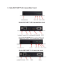
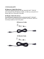
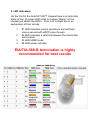
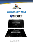
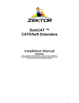
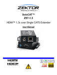
User Manual
SoloCAT™ HD
HDMI over HDBaseT Extender
with bi directional
IR & RS232.atlona.com |
1-877-536-
Table of Contents
1.
2.
3.
4.
5.
6.
7.
8.
9.
10.
11.
Included items pg2
Safety notices pg 3
About the SoloCAT HD™ pg 3
Specifications pg 4
SoloCAT HD™ panel connections pg 5
Installations pg 6
LED indicators pg 7
IR information pg 8
CAT5 termination table pg 8
Troubleshooting pg 9
Warranty pg 10
Included items
•
•
•
•
•
•
•
•
SoloCAT™ HD HDMI Transmitter x 1
SoloCAT™ HD HDMI Receiver x 1
Zektor Gripper™ HDMI cable securing
support brackets x2
15V Switching Power Supply x 2
IR sender x1
IR receiver x1
HDMI cable x1
User’s Manual x 1
Safety and Notice
Please read and follow the safety instructions to protect
yourself from possible injury and to minimize the risk of
damage to the unit.
Follow all instructions and warnings marked on this unit
Do not attempt to service this unit yourself, except where
explained in this manual
Provide proper ventilation and air circulation
Do not use near water
Keep objects that might damage the device and assure
that the placement of this unit is on a stable surface
Use only the power adapter and power cords and
connection cables designed for this unit
Do not use liquid or aerosol cleaners to clean this unit
Always unplug the power to the device before cleaning
About the SoloCAT HD™
The SoloCAT HD ™HDMI over CAT5e/6 Extender kit is
designed to be HDMI 1.4a compatible and 3D capable,
enabling the reliable transmission of the HDMI; bi directional IR
and bi directional RS232 signals up to 330ft in 1080p HD (even
2k/4k resolutions and 3D format).
Because the SoloCAT HD™ is HDMI 1.4 compatible it allows
you to take full advantage of the new technology by supporting
much higher resolutions than 1080p or 1440p including 2k
(2048x1080p) and 4k (4096×3072) resolutions. Future
versions of this device will add the capability for Ethernet data
channel, allowing other HDMI 1.4 enabled devices to share a
network connection for internet connectivity. Additionally for
future versions, the audio return channel which will send the
audio signal back from the display to a receiver or other audio
device.
Since the SoloCAT HD™ has bi-directional IR, it is the perfect
device for multi-room applications and third party control
systems. With bi-directional communication from a remote
control or control system, commands can be sent from the
remote location back to the main equipment center or the other
way around.
Note: The maximum usable distance depends on the quality
and characteristics of the cables. Higher resolutions and longer
transmission distances work better with low skew cables
(<25ns/100m) for the best performance. Unshielded Cat5e/6
with metal RJ-45 connectors and 568-B termination will provide
best results.
For more information about HDMI over HDBaseT technology
you can visit www.valens-semi.com.www.atl
1. Specifications
HDMI compliant to v1.4a
3D capable
HDMI Connector 19 pin type female connector
HDMI Source Input Port 1
HDMI Sink Output Port 1
Source Port Connector Standard 19 pin HDMI
Display Device Port Connector Standard 19 pin HDMI
Link Connector RJ-45 Shielded
HDCP Compliant
Power on LED Indicator
Input TMDS signal 1.2 volts (peak-to-peak)
Input DDC signal 5 volts (peak-to-peak)
Uncompressed video resolution 1080p / 1920x1200 / 2k
(2048x1080p) and 4k (4096×3072)
Deep Color 24-48 bits
Video Bandwidth Up to 10.2GHz
Vertical Frequency Range 50 ~60 Hz
Audio Performance PCM (7.1ch), Dolby Digital, True HD, DTSHD & Master Audio
Power Consumption (max.) 15 Watts
Operation Temperature 0°C to 70°C.
Power Supply 5V 2A (universal)
Zektor Gripper™ HDMI cable support brackets
Dimension (in) 6 x 5 x 1
Weight (lb) 2.3
Supports Refresh Rates: 24Hz, 30Hz, 60Hz
Supports Bi-directional IR transmission (38Khz only)
LED indicators for operation modes
Supports transmission distances up to 328ft @ 1080p 50/60Hz
Easy to install, simple to operate and the most effective solution
for long signal extension.
HDMI over HDBaseT is the cost effective way to reliably
transmit long distance HDMI for commercial, residential, digital
signage applications over a single CAT5e/6 cable.
2. SoloCAT HD™v2 transmitter front
SoloCAT HD™v2 transmitter rear
SoloCAT HD™v2 receiver front
SoloCAT HD™v2 receiver rear
3. Installation
1. Turn off power at connected sources
2. Connect the HDMI® extension cable between the source
and the “HDMI® IN” port of the SoloCAT HD™
3. Connect the HDMI® cable between the display and the
“HDMI® OUT” port of SoloCAT HD™
4. Connect the CAT.5 cables between the HDMI-ELW “LINK”
port and the HDMI-SRW or HDMI-ERW “LINK” port of
extender.
5. Connect the power cord and turn on the extender.
6. Turn on the source(s) and display(s)
Note: when the SoloCAT HD™ is in BYPASS mode the LINK
port should be left unused.
7. Use CAT5e/6 cables to link the transmitter and the receiver.
As in all installations, poor quality cable will result in lesser
quality results and occasionally intermittent problems. However,
in our testing we used off the shelf CAT5e cable from Home
Depot® which worked fine and provided an outstanding result.
Zektor recommends using EIA/TIA 568B for CAT5e/6
termination. We have included a reference diagram below for
your convenience.
8. Make sure that the source, the transmitter, the receiver and
the displays are all properly connected. Zektor has designed
and manufactured a new HDMI cable support bracket, the
Zektor Gripper™, to help ensure that your HDMI cable remains
properly connected to our transmit / receive pair.
9. Connect your serial cables if using the bi directional serial
function.
10. Properly install your IR blaster and sender. Incorrect
installation can damage your SoloCAT HD™ extender pair. If
TX/RX (transmit & receive) are mistakenly connected in the
wrong connections, the IR eye can get damaged. 3rd party IR
emitters/blasters, must be able to handle up to 60 KHz 1Note: After initial power on, allow for EDID verification and
HDCP handshake. A visible image at the display after initial
power on can take up to 5 seconds.
4. Bi directional IR
IR Receiver Cable Directions:
Insert the supplied receiver into the SoloCAT HD™ “IR2 IN”
port and place the IR Receiver Cable, so that you can point to it
easily with your IR remote controller.
IR Blaster Cable Directions:
Plug IR blaster cable plug into the SoloCAT HD™ “IR OUT”
port, It sits in front of the source receiver’s IR sensor, which is
normally located on the front-panel.
IR Receiver Cable
GND
+V
Si g
IR Blaster Cable
NC
P+
N-
5. LED Indicators
On the front of the SoloCAT HD™ chassis there is a horizontal
block of four (4) green LED’s that is marked “Status” on the
chassis just above the LED’s. From Left to Right this is an
explanation of their activity:
1.
2.
3.
4.
#1 LED indicates normal operations and will flash
once a second with HDCP pass through.
#2 LED indicates a valid link between the transmitter
and receiver.
#3 LED HDMI mode
#4 LED power indicator
EIA/TIA-568-B termination is highly
recommended for best results
EGISTR11ATION
EZ Crimp RJ45 crimp connectors:
We have conducted long term tests on these popular
connectors. HDBaseT does not appear to be as
susceptible to interference as other technologies. To
eliminate any potential corrosion on exposed wire ends as
well as EMI / RFI interference, standard crimp RJ45
connectors should be used when possible.
6. Troubleshooting
Problem: No picture
Action: Make sure your source is working properly and
outputting video. Check all connections from the source
and control ports to the transmitter and from the receiver
to the display and control ports. Make sure you have
activity lights on the SoloCAT HD™ transmitter and
receiver. If no lights, remove all connections including
power. Reconnect serial and/or IR if used, and power.
Reconnect CAT cable. Within 1-2 seconds you should see
activity lights on the transmitter and receiver. Within 2-3
seconds you should have a picture on your display.
Action: Verify your cable is no longer than 328’. Make sure
termination is identical on both ends. Verify your cable is
not pinched, cut or has a defect. It is always good to have
a good, known working cable available to verify.
Problem: IR/RS232 not communicating
Action: Make sure all DIP switches are in the furthest upright
position. Double check all connections. IR and RS232 activity
is immediate and requires no delay or sync time.
Problem: No power
Action: Check for power at electrical source. Remove and
reconnect to one side of the SoloCAT HD. Only use DC wall
power supplies provided by Zektor. If problem persists, call
Zektor tech support and request a replacement power supply.
Problem: Intermittent picture, pixilation
Action: Check all cabling. This is the most action to resolve
issues. If you are using EZ Crimp RJ45 connectors make sure
the end of the cable is not corroded and/or shorting out. Reterminate to T568B on both ends with standard crimp RJ45
connectors. Check all HDMI connections.
Remove all power. Apply power and connections as described
in the installation section.
7. Limited Warranty
Zektor Incorporated (“Zektor”) warrants the SoloCAT™ HD
extender to be free from defects in the material and
workmanship for 2 years from the date of purchase from the
Zektor or an authorized dealer. Should this product fail to be in
good working order within the 2 year warranty period, Zektor, at
its option, repair or replace the unit, provided that the unit has
not been subjected to accident, disaster, abuse or any
unauthorized modifications including static discharge and
power surge. This warranty is offered by Zektor for its BUYER
with direct transaction only. This warranty is void if the warranty
seal on the metal housing is broken.
A unit that fails under conditions other than those covered will
be repaired at the current price of parts and labor in effect at
the time of repair. Such repairs are warranted for 90 days from
the day of reshipment to the BUYER. If the unit is delivered by
mail, customer agrees to insure the unit or assume the risk of
loss or damage in transit. Under no circumstances will a unit be
accepted without a return authorization number.
The warranty is in lieu of all other warranties expressed or
implied, including without limitations, any other implied warranty
or fitness or merchantability for any particular purpose, all of
which are expressly disclaimed.
Product must not be physically damaged or chassis opened.
All original parts must be returned to Zektor unless instructed
otherwise. Any product that shows signs of abuse or extreme
wear will not be warranted. All products must be returned in
reasonable condition.
The content of this manual has been carefully checked and is
believed to be accurate. However, Zektor assumes no
responsibility for any inaccuracies that may be contained in this
manual. Zektor will NOT be liable for direct, indirect, incidental,
special, or consequential damages resulting from any defect or
omission in this manual, even if advised of the possibility of
such damages. Also, the technical information contained herein
regarding the Zektor Incorporated SoloCAT™ features and
specifications is subject to change without further notice.
NO LIABILITY FOR DAMAGES
IN NO EVENT SHALL ZEKTOR INCORPORATED OR ITS
SUPPLIERS BE LIABLE FOR ANY DAMAGES INCLUDING,
BUT NOT LIMITED TO, SPECIAL, INCIDENTAL,
CONSEQUENTIAL, OR INDIRECT DAMAGES FOR
PERSONAL INJURY, LOSS OF BUSINESS PROFITS,
BUSINESS INTERRUPTION, LOSS OF BUSINESS
INFORMATION, OR ANY OTHER PECUNIARY LOSS)
ARISING OUT OF THE USE OF OR INABILITY TO USE THIS
PRODUCT, EVEN IF ZEKTOR INCORPORATED HAS BEEN
ADVISED OF THE POSSIBILITY OF SUCH DAMAGES.
ZEKTOR INCORPORATED AND ITS SUPPLIERS’ ENTIRE
LIABILITY UNDER ANY PROVISION OF THIS AGREEMENT
SHALL BE LIMITED TO THE AMOUNT ACTUALLY PAID BY
YOU FOR THE PRODUCT. SOME JURISDICTIONS DO NOT
ALLOW THE EXCLUSION OR LIMITATION OF LIABILITY
FOR CONSEQUENTIAL OR INCIDENTAL DAMAGES; THE
ABOVE LIMITATION MAY NOT APPLY TO YOU.
This area left blank intentionally