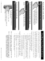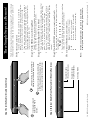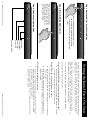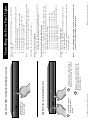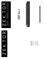
1
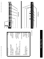
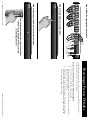
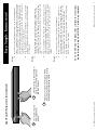
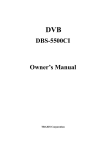
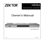
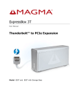
www.zektor.com
858•748•8250
Poway, CA 92064
Suite 401
12675 Danielson Ct
ZEKTOR
Z E K T O R
Rev 2
ZEK T OR
2
3
4
High Definition Component Video Switch
1
HDS4.1
02/22/2006
Digital Video / Component Video / Multichannel Audio
H ome T he a te r Sw i tches
Z E K T O R
ii
Contents
What’s Inside ..................................... 1
An Overview of the HDS4.1 ................ 3
Easy, Simple, Instructions! ................. 5
Three Simple Steps to a Remote! ........ 7
Controlling the Front Panel Lights ..... 9
Adjusting the Front Panel Intensity .. 11
Setting the Initial Power On State .... 13
Disabling Front Panel or Remote ...... 15
Resetting to Factory Defaults ........... 17
Specifications .................................. 19
Warranty Policy ............................... 20
Contact Information ........................ 21
HDS4.1 Component Video Switch
Contact Information
Instructions for Returning Items
Please retain the dated sales receipt as evidence of the date of
purchase. You will need it for any warrant y ser vice. I f you bought
the produc t through a dealer, installer, or reseller, you will need to
return the produc t to the point of sale.
E-mail us, or call us, using the information listed under “Customer
S er v i ce Con t a c t I nfor m a t i o n”, fo r a R e t u r n to M a n u f a c t u re r Au t h o r i z a t i o n ( R MA) n u m b e r. D e s c r i b e b r i e f l y t h e re a s o n s fo r yo u r re q u e s te d re t u r n .
Yo u m u s t rece i ve a n R MA # b e fo re yo u re t u r n a ny g o o d s to u s. The
R MA # m u s t a p p e a r o n yo u r re t u r n p a c k in g l a b e l o r o n t h e o u t s i d e
of the box. M erchandise without a RMA # will be refused. RMA’s are
valid for t went y (20) days from date of issuance.
A l l re t u r n e d m e rc h a n d i s e m u s t b e s h i p p e d i n t h e o r i gi n a l p a c k a gi n g.
I f i t i s n o t i n t h e o r i gi n a l p a c k a gi n g, Z E K TOR w i l l n o t b e h e l d l i a b l e
for damage during shipment. Shipments of returns must be prepaid,
a n d we w i l l n o t a cce p t CO D re t u r n s.
Customer Service Contact Information:
858-748-8250
858-748-8224
[email protected]
www.zektor.com
Zektor
12675 Danielson Ct.
Suite 401
Poway, CA 92064
Phone:
Fax:
E-mail:
Website:
HDS4.1 Component Video Switch 21
20 HDS4.1 Component Video Switch
Shipment of produc t is as adver tised by produc t. Upon receipt of
merchandise inspec t produc t carefully, should you find that the
produc t does not meet your expec tations, or satisfac tion, contac t
us at once and tell us your concerns, so we may make ever y effor t to
satisfy your purchase.
Return & Exchange
S ome states/countries do not allow the exclusion or limitation of
incidental or consequential damages, so the above limitation or
exclusion may not apply to you. S ome states/countries do not allow limitations on how long an implied warrant y lasts, so the above
limitation may not apply to you. This warrant y gives you specific
legal rights, and you may also have other rights that var y from state
to state and countr y to countr y.
Repair or replacement, as provided under this warrant y, is your
exclusive remedy. ZEK TOR shall not be liable for any incidental or
consequential damages. I mplied warranties of merchantabilit y and
fitness for a par ticular purpose on this produc t are limited in duration to the duration of this warrant y.
I n order to keep this warrant y in effec t, the produc t must have been
h a n d l e d a n d u s e d a s p re s c r i b e d i n t h e i n s t r u c t i o n s a cco m p a ny i n g
this warrant y. This warrant y does not cover any damage due to accident, misuse, abuse, or negligence. This warrant y is valid only if the
produc t is used as specified in the produc t documentation.
ZEK TOR warrants this produc t against defec ts in material and workm a n s h i p u n d e r n o r m a l u s e a n d s e r v i ce fo r t wo ye a r s f ro m t h e o r i gi nal date of purchase. ZEK TOR, at its option, shall repair or replace
the defec tive unit covered by this warrant y.
Warranty Policy
Warranty Policy
HDS4.1
Power Supply M odule
This User ’s M anual
HDS4.1 Component Video Switch
I f anything is missing please get in touch with us as soon as possible
so that we can correc t the situation.
1.
2.
3.
The following should be included:
Please take this time to verify the contents of the HDS4.1 box.
1
Ever y care has been taken to assure you of a successful installation
and subsequent operations of your new HDS4.1 video switch, however
should something go wrong, and warrant y repair work is needed, we
request that you hold on to the original pack aging materials.
Th a n k yo u fo r yo u r p u rc h a s e o f yo u r H D S 4 . 1 H i g h D e f i n i t i o n Co m p o nent Video Switch.
What’s Inside
2
R/V
Pb/B
L/H
ZEKTOR
1
Y/G
C/V
Pr/R
2
R/V
Y/G
L/H
Pb/B
C/V
Pr/R
3
R/V
Y/G
1
L/H
Pb/B
4
R/V
Y/G
L/H
Pb/B
C/V
Pr/R
3
OUT
R/V
Pb/B
L/H
Pr/R
C/V
4
1
OUT
2
OUT
3
4
Y/G
Rear Panel
2
Front Panel
C/V
Pr/R
HDS4.1 Component Video Switch
1
3
DIGITAL AUDIO
2
4
OUT
9VDC
1
2
3
4
5
6
1
2
3
4
5
Specifications:
Analog Channels
Bandwidth @ -0.1db:
Bandwidth @ -3db:
Resolution:
Input Coupling:
Output Coupling:
Two Year Parts and Labor
90-120VAC, 60Hz, 15W
90-264VAC, 47-63Hz, 15W
Wall Mount, 9V @ 500ma, U.L. Listed
Rack Mountable, 17”W x 6.5”D x 1.75”H
4 Coax, 4 Optical, (Auto conversion between formats)
2 Coax, 1 Optical, (Simultaneous)
13.2Mb/S
PCM, DD5.1, DTS, All modes
200mV - 7.0V (PC Soundcard Compatible)
500mV Nominal
0Hz - 70MHz, All channels
Greater than 200MHz, All channels
480i - 1080p, All HDTV modes
D.C.
D.C.
Specifications
Digital Audio Channels
Inputs:
Outputs:
Maximum Transfer Rate:
Digital Audio Modes:
Coax Input Level Range:
Coax Output Level:
Power Requirements:
Optional International:
Power Supply:
Dimensions:
Warranty:
HDS4.1 Component Video Switch 19
18 HDS4.1 Component Video Switch
Power I ndicator. Lights up in standby mode.
S elec tion LEDs. I ndicate currently selec ted inputs.
I nput S elec tion Buttons.
I nfrared Remote S ensor Window.
I nfrared Received I ndicator. Flashes when IR is received.
Power Toggle Button.
5.
4.
2.
3.
1.
HDS4.1 Component Video Switch
Analog I nputs. Each input consists of six equivalent channels. The channels are colored and labeled for convenience,
however all six channels are of equivalent bandwidth and
func tionalit y, and may be interchanged as desired.
Analog Outputs.
Digital Audio I nputs. Each input has an associated digital
audio channel with both a Coax and an Optical connec tion.
Only one of the t wo t ypes of inputs can be ac tive at any
time. The HDS4.1 will auto -selec t bet ween the t wo t ypes of
signals. I f a signal is supplied to both the Coax and Optical
i n p u t s, t h e Co a x s i gn a l i s give n p r i o r i t y.
DC Power Jack Connec tor. Plug in the supplied power
adapter into this jack .
Digital Audio Outputs. All digital audio inputs are automatically conver ted to both Coax and Optical outputs. All three
outputs are available at all times, and are all individually
buffered to allow driving three different digital audio de vices simultaneously.
Rear Panel Connections:
1.
2.
3.
4.
5.
6.
Front Panel Controls:
An Overview of the HDS4.1
3
4
R/V
L/H
Pb/B
C/V
Pr/R
2
R/V
Y/G
L/H
Pb/B
C/V
Pr/R
3
R/V
Y/G
To
DVD
L/H
Pb/B
C/V
Pr/R
4
R/V
Y/G
L/H
Pb/B
Unused
Input
To
Game
Console
2
C/V
Pr/R
OUT
3
L/H
Pr/R
C/V
4
1
OUT
2
OUT
3
To
Composite
Monitor
w/Analog
Audio
R/V
Pb/B
To
Projector
or
Monitor
1
2
9
6
3
3
4
DIGITAL AUDIO
3
4
OUT
To Home Theater
Receiver’s Digital
Audio Input
9VDC
To Power
Module
Turn to the next chapter for simple instructions
on how to setup the HDS4.1 for use with
any existing remote!
2
2
To DVD
Digital Audio
To
Cable Box
Digital Audio To Game
Console
Digital Audio
Y/G
4
Step 1: Make the appropriate connections.
1
Y/G
To
Cable
Box
1
Step 2: Press buttons to select an input.
ZEKTOR
5
+
_
1
Step 3: Or use nearly ANY remote to select an input.
ZEKTOR
1
8
POWER
4
+
_
CH
0
7
VOL
HDS4.1 Component Video Switch
Resetting to Factory Defaults
I f, for whatever reason, you’d like to reset your HDS4.1 back to its
fac tor y condition, this is easily done...
Step 1: Reset All Parameters to Factory Defaults
1.
2.
3.
First press and hold the Power button
While continuing to hold the Power Button, press and hold
both the ‘2’ and ‘3’ buttons.
Af ter holding all buttons for about ‘4’ seconds, the display
will flash indicating all parameters have been restored to
their fac tor y programmed values.
HDS4.1 Component Video Switch 17
Start by pressing and
holding the Power
button...
3
1
16 HDS4.1 Component Video Switch
1
ZE KT O R
4
...while continuing to hold the Power
button, press and hold both the ‘2’
and the ‘3’ buttons.
3
After about 4 seconds, the display will flash
indicating all parameters have been restored
to their factory programmed values.
2
2
Step 1: Reset All Parameters to Factory Defaults
Use nearly any remote to control your HDS4.1!
Using any remote to operate the HDS4.1 is a simple matte r o f p a i r i n g u p t h e H D S 4 . 1 w i t h t h e re m o te. Th e re m o te
doesn’t have to be a universal remote (although it can be),
a ny re m o te f ro m a n o l d T V o r V C R w i l l wor k j u s t f i n e.
Using Zektor ’s exclusive I ntelligent-IR™, setup is easy! The
H D S 4 . 1 d o e s a l l t h e wor k !
To switch bet ween any of the four inputs, simply press
the button for the desired input. I f the HDS4.1 is in the
s t a n d by, i t w i l l t u r n o n . Th e H D S 4 . 1 w i l l t h e n s w i tc h to t h e
selec ted input, and the associated LED will light to indicate
this.
To place the HDS4.1 back into the standby mode, press and
release the Power Toggle button. The channel LEDs will all
go blank , and the standby LED will light up. Press the Power
Toggle button again to re -selec t the previously selec ted
input.
Use the analog input connec tions to switch component
video / composite video / analog audio or any combination
o f t h e a b ove s i gn a l s to t h e H D S 4 . 1 ’s a n a l o g o u t p u t co n n e c tors. Use the digital audio connec tors to switch digital audio signals, with full format conversion bet ween the optical
and coax digital audio formats.
Plug the power module into the HDS4.1, and plug the module into a standard A.C. wall receptacle. The standby LED
will light up.
HDS4.1 Component Video Switch
Turn to the nex t chapter for simple instruc tions
on how to pair up the HDS4.1 with any remote!
•
•
•
Step 3...
•
•
Step 2...
•
•
Step 1...
Easy, Simple, Instructions!
5
6
1
2
3
4
Step 1: Put the HDS4.1 into the Setup Mode
ZEKTOR
Press and hold the Power Button for 4 secs.
The standby LED will blink wildly, and the
selection LEDs will start sequencing to the
right. (You’ll know it when it happens!)
1
2
2
9
6
3
2
3
4
That’s it! The HDS4.1 now operates with
your new remote control!
Power 1 2 3 4 8 9
Press the following sequence of buttons on
your remote control:
4
...the standby LED will flash slower,
and all the other LEDs will turn off.
3
Step 2: Press the ‘1’ button for Intelligent-IR™ learning
ZEKTOR
Once the ‘1’ button
is pressed...
5
1
Step 3: Teach the HDS4.1 its new IR codes
ZEKTOR
1
8
POWER
4
CH
+
_
0
7
VOL
+
_
HDS4.1 Component Video Switch
Disabling Front Panel or Remote
I f you are not planning on using a remote control with your HDS4.1,
you might want to disable its remote control func tion.
Or if you have a household with young curious fingers that likes
playing with buttons, you also have the capabilit y of disabling the
front panel switches and only operating the HDS4.1 with a remote.
To enable/disable the front panel switches or remote capabilities...
Step 1: Enter the Enable / Disable control state
1.
2.
3.
•
First press and hold the Power button
While continuing to hold the Power Button, press and hold
the ‘4’ button.
Af ter holding both buttons for about ‘4’ seconds, the standby LED will star t flashing quick ly indicating you are now
able to enable / disable front panel buttons and IR control
func tions.
The front panel selec tion LEDs now indicate the state of the
front panel and IR control settings:
I f ‘3’ is lit, then the Front Panel buttons are ENABLED.
I f ‘4’ is lit, then the IR remote func tions are ENABLED.
Use the ‘3’ button to ENABLE / DISABLE the front panel
buttons.
Use the ‘4’ button to ENABLE / DISABLE the IR remote control func tions.
When finished, press the ‘Power ’ button to save new settings and return to normal operations.
Step 2: Enable or Disable Front Panel and / or IR control
•
•
•
Note 1: The HDS4.1 will not allow you to disable both the front
panel and IR controls at the same time.
Note 2: Disabling the front panel buttons does not disable the
a b i l i t y to e nte r t h e S e t u p M o d e s. Eve n w i t h t h e f ro nt
panel disabled you can per form the above steps, allowing you to once again enable the front panel buttons.
HDS4.1 Component Video Switch 15
Start by pressing and
holding the Power
button...
1
3
4
...while continuing to hold the Power
button, press and hold the ‘4’ button.
3
After about 4 seconds, the standby LED
will flash quickly, and the display will indicate the current enable / disable statuses.
2
2
1
14 HDS4.1 Component Video Switch
Z EK TO R
2
3
4
Exit Setup Mode
Enable / Disable
Front Panel Buttons
Enable / Disable
IR Control Functions
Step 2: Enable or Disable Front Panel and / or IR Control Functions
1
ZE KT O R
Step 1: Enter the Enable / Disable Control State
The HDS4.1 is placed into the setup mode by pressing and
holding the Power button for about 4 seconds.
Power 1 2 3 4 8 9
That ’s it! The HDS4.1 will return to the state it was in before
s e t u p, a n d w i l l n ow wor k w i t h yo u r n e w re m o te !
Note:
Toggles the HDS4.1’s power.
S elec ts inputs 1 through 4.
Tur n s o n t h e H D S 4 . 1 ( D i s c re te O N )
Tur n s o f f t h e H D S 4 . 1 ( D i s c re te O F F ) .
HDS4.1 Component Video Switch
All remote control codes are saved in non-volatile
memor y and will not be lost during a power failure.
Power
1-4
8
9
The new control buttons on your remote are...
•
On your remote control, press the following buttons, in the
following order :
Step 3: Teach the HDS4.1 your new remote control codes
•
•
There are many options available in the setup mode, but for
now all we’re interested in is the I ntelligent-IR™ learning
mode. This is selec ted by pressing the ‘1’ button.
Once the ‘1’ button is pressed, the standby LED will flash
s l owe r a n d a l l t h e o t h e r L E D s w i l l t u r n o f f. Th e H D S 4 . 1 i s
now waiting for new IR codes to be sent from your remote
control.
Step 2: Select the Intelligent-IR™ Learn Mode
•
•
Star t by pick ing the remote you’d like to use with the
HDS4.1. I f the remote you plan on using is not programmable (for instance, from an old T V ), sk ip the nex t step.
I f you plan on using a universal remote, star t by setting it
up as a remote for a T V or VCR that you do not own. (For
instance if you don’t own a S ony T V, setup your universal
remote to control a S ony T V.)
Step 1: Put the HDS4.1 into the Setup Mode
•
•
Pick a remote, any remote!
The HDS4.1 features Zektor ’s Exclusive I ntelligent-IR™, and with ver y
few exceptions can be setup to use any remote you can point at it!
Three Simple Steps to a Remote!
7
8
1
2
3
4
Step 1: Place the HDS4.1 into the Setup Mode
ZEKTOR
2
2
3
3
4
4
Exit Setup Mode
Auto-Fade
Always Bright
Always Dim
Always Off
Press and hold the Power Button for 4 secs.
The standby LED will blink wildly, and the
selection LEDs will start sequencing to the
right.
1
Step 2: Select “Lighting Mode” option
ZEKTOR
After ‘3’ is pressed, the standby
LED continues to flash, and the
front panel will display the current Light Mode setting.
1
Step 3: Choose a new lighting mode
ZEKTOR
HDS4.1 Component Video Switch
Setting the Initial Power On State
As long as the HDS4.1 is plugged in, it will remember the previously
selec ted input in standby mode. When powered up by pressing the
Power button, it will return to that previously selec ted channel.
H owever, i f p owe r i s re m ove d ( fo r i n s t a n ce a p l u g s t r i p u s e d to
p owe r t h e H D S 4 . 1 i s t u r n e d o f f ) , a n d t h e n re - a p p l i e d, t h e H D S 4 . 1 ’s
default behavior is to enter into the standby mode.
I t is possible to change the power on behavior of the HDS4.1.
Setup the HDS4.1 to your preferred power on state.
Use the front panel buttons to setup the HDS4.1 to the op erating settings you’d like at initial power up.
To change the power on defaults...
Step 1:
•
Step 2: Save the new initial power on state.
1.
2.
3.
First press and hold the Power button.
While continuing to hold the Power button, press and hold
the ‘1’ button.
Af ter holding both buttons for about ‘4’ seconds, the display will blink indicating the new power on defaults have
been accepted.
You can test the new defaults by either disconnec ting the
power supply from the back of the HDS4.1 or by unplugging the power supply from the wall.
Reconnec t power. The HDS4.1 will power up into your new
power on default state.
Test the new initial power on state
•
•
HDS4.1 Component Video Switch 13
1
2
3
Start by pressing and
holding the Power
button...
1
12 HDS4.1 Component Video Switch
1
ZE KT O R
3
4
...while continuing to hold the Power
button, press and hold the ‘1’ button.
3
4
After about 4 seconds, the display will
flash indicating the new power on state
has been accepted.
2
2
Step 2: Save the new initial power on state
Setup the HDS4.1 to
the initial power on
state you’d prefer.
Z EKTOR
Step 1: Set the HDS4.1 to the preferred initial power on state
automatically fade from bright to dim
inac tivit y.
are always at the bright level.
are always at the dim level.
are turned off.
The intensities of the both the bright and dim levels can be
adjusted as well, this is explained in the nex t chapter.
Front panel lights
af ter 4 seconds of
Front panel lights
Front panel lights
Front panel lights
The HDS4.1 is placed into the setup mode by pressing and
holding the Power button for about 4 seconds.
Press the ‘3’ button to selec t the “Lighting M ode” option.
The front panel selec tion LEDs now indicate the currently
selec ted light mode as follows:
I f ‘1’ is lit, then front panel lights are always off.
I f ‘2’ is lit, then front panel lights are always dim.
I f ‘3’ is lit, then front panel lights are always bright.
I f ‘4’ is lit, then front panel lights auto -fade from bright to
dim af ter 4 seconds of inac tivit y.
Note:
HDS4.1 Component Video Switch
The lighting mode setting is saved in non-volatile memor y and is not affec ted by a power failure.
Choose a new light control mode by pressing the associated selec tion button.
Pre s s t h e Power B u t to n to s ave t h e n e w m o d e a n d re t u r n to
normal operations.
Step 3: Choose a new lighting mode
•
•
•
•
Step 2: Select the Lighting Mode option
•
Step 1: Enter the Setup Mode
To change the front panel lighting mode...
Note:
•
•
•
•
There are four different front panel light modes available on the
HDS4.1. They are:
Controlling the Front Panel Lights
9
1
2
3
4
Step 1: Place the HDS4.1 into the Setup Mode
ZEKTOR
2
2
3
3
4
4
Exit Setup Mode
Press to Brighten LEDs
Press to Dim LEDs
Selects BRIGHT level
Selects DIM level
Press and hold the Power Button for 4 secs.
The standby LED will blink wildly, and the
selection LEDs will start sequencing to the
right.
1
Step 2: Select “Front Panel Intensity” option
ZEKTOR
After ‘4’ is pressed, the standby LED continues to flash, and the front panel will
display the current intensity setting.
1
Step 3: Adjust front panel intensities
ZEKTOR
10 HDS4.1 Component Video Switch
Adjusting the Front Panel Intensity
The bright and dim levels of the front panel lights of the HDS4.1 are
user adjustable, allowing the HDS4.1 to blend into a wide range of
lighting conditions.
To change the front panel intensities...
The HDS4.1 is placed into the setup mode by pressing and
holding the Power button for about 4 seconds.
Step 1: Enter the Setup Mode
•
Step 2: Select the Front Panel Intensity option
•
•
Press the ‘4’ button to selec t “Front Panel I ntensit y ” option.
The front panel selec tion LEDs now indicate the front panel
intensit y settings:
I f ‘1’ is lit, then the DIM level is being adjusted.
I f ‘2’ is lit, then the BRIGHT level being adjusted.
‘3’ and ‘4’ are always lit.
The new intensity settings are saved in non-volatile
memor y and are not affec ted by a power failure.
Use the ‘1’ and ‘2’ buttons to switch bet ween the DIM and
BRIGHT settings.
Use the ‘3’ button to decrease the intensit y of the front
panel lights.
Use the ‘4’ button to increase the intensit y of the front
panel lights.
You cannot make the DIM level brighter than the BRIGHT
level, and you cannot make the BRIGHT level dimmer than
the DIM level.
Once the front panel intensities are acceptable, press the
Power button to save the new settings and exit the setup
mode.
Step 3: Adjust Front Panel Intensities
•
•
•
•
•
Note:
HDS4.1 Component Video Switch 11