1
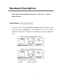
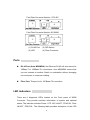
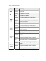
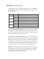
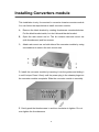
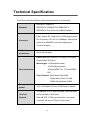
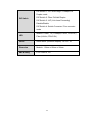
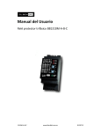
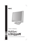
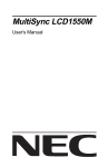
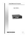
Fast Ethernet Converter User Guide MICROSENS Rev.1.25 Jan-2010 Content Introduce ........................................................... 1 Features .......................................................... 2 Package Contents .......................................... 3 Hardware Description ...................................... 4 Front Panel ..................................................... 4 Ports................................................................ 5 LED Indicators ................................................ 5 DIP-switch ....................................................... 7 Rear Panel ...................................................... 8 Installing Converters module .......................... 9 Cabling .......................................................... 10 Troubles shooting .......................................... 11 Optical Fiber Specification ............................ 12 Technical Specification ................................. 13 i Introduce The Fast Fiber Converter Module (Auto MDI/MDIX) is a cost-effective solution for the converting between 10/100Base-TX and 100Base-FX cabling, It allows you to extend the cabling distance of your 100Base-FX network up to 2 kilometers for multi-mode fiber or 30 kilometers for single-mode fiber. The Fast Fiber Converters module provides you with one Fiber connector for your fiber optic cable (SC) and one Ethernet RJ-45 port (Auto MDI/MDIX) for your 100BaseTX copper cable connection. There are 4 DIP- switches to set the operation mode for UTP, Fiber ports and link loss forwarding function. The Fast Fiber Converter Module also supported WDM technology that offers a cost efficient solution and allows a grouping of different services on existing optical fibers inside. WDM Converter module converts signals between 10/100Base-TX and 100Base-FX cabling, and incorporates WDM technology. The WDM technology makes transmit (TX) and receive (RX) lines onto a single fiber, which reduces half cabling cost. A pair of WDM converters (wavelength 1310 and 1550 nm) should be installed at both ends of the single fiber cable. The fiber cabling can extend the connectivity distance up to 20 kilometers. The UTP port (RJ-45 connector) of this converter supports Auto MDI/MDIX function. Besides, there are 4 DIP- switches on the front panel of the converter to set the operation mode and Link Loss Forwarding Function. The Fast Fiber Converter Module can be slotted in Multi-Converter Chassis up to 10 optional modular converter units, which allows your network connectivity to be more flexible. It also can be use stand-alone without slot in Multi-Converter Chassis. 1 Features Fast Fiber Converter Module Comply with IEEE 802.3, 802.3u, and 802.3x standards. Convert between UTP cabling and Fiber-optic cabling. One RJ-45 connector, Auto-MDI/MDIX for UTP port. Support 10/100 Mbps Auto-negotiation for UTP port. Fiber cabling connectivity up to 30Km. Store-and-forward switching architecture. One fiber connector (SC) for 100Base-FX. 4DIP-switches to set the operation mode and Link- Lost-Forwarding function. 6 LEDs for per port: 100, Link, Activity, Full, Collision, and per unit Power. External DC power adapter 12V/1A. Two types of module: Stand-alone and mounted in converter chassis. FCC Class A, CE, UL, and CUL Mark certification WDM Converter Module Comply with IEEE 802.3, 802.3u, and 802.3x standards. Convert between UTP cabling and Fiber-optic cabling. WDM (Wavelength Division Multiplexing) supports single fiber converter, transporting Bi-direction full-duplex signal over a single fiber simultaneously. One RJ-45 connector, Auto-MDI/MDIX for UTP port. Support 10/100 Mbps Auto-negotiation for UTP port. One Single-SC Style Single-Mode Connector for 100 Base- FX fiber cable. Fiber cabling connectivity up to 20Km. Uses store-and-forward switching architecture. 4DIP-switches to set the operation mode and Link- Lost-Forwarding function. 2 6 LEDs for Per port: 100, Link/Activity, Full/Collision, Per Unit: Power. External DC power adapter 12V/1A. Two types of module: Stand-alone and mounted in converter chassis. FCC Class A, CE Package Contents Beware of which type of converter module that you have purchased. And, please refer to the package content list below to verify them against the checklist. Stand-alone converter module package contains following items. ¾ Modular Fast Fiber Converter (or WDM converter) ¾ AC-DC Power Adapter ¾ User Guide Mounted in converter chassis converter module package contains following items. ¾ Modular Fast Fiber Converter (or WDM converter) ¾ Rack mount kit ¾ User Guide Compare the contents of your converter module with the checklist above. If any item is damaged or missing, please contact your local dealer for service. 3 Hardware Description Fast Fiber Converter Module dimension (L x W x H) is : 119mm x 85mm x 26mm Front Panel The Front Panel of the Fast Fiber Converter Module consists of one RJ-45 Port (Auto MDI/MDIX), 6 LED Indicators (UTP 100, LK/ACT, FDX/COL, Fiber LK/ACT, FDX/COL and PWR) and one fiber 100Base-FX Port. WDM converter (Single Mode/ 1310m) 2 1 3 4 WDM converter (Single Mode/ 1550m) 2 1 3 4 (1) RJ-45 Port (3) DIP-Switch (2) LED (4) SC Connector 4 Fast Fiber Converter Module-- ST & SC 2 1 3 4 Fast Fiber Converter Module--SC-SM30 2 1 3 4 (1) RJ-45 Port (3) DIP-Switch (2) LED (4) Fiber Connector Ports RJ-45 Port (Auto MDI/MDIX): the Ethernet RJ-45 will auto-sense for 10Base-T or 100Base-TX connections. Auto MDI/MDIX means that you can connect to another Switch or workstation without changing non-crossover or crossover cabling. Fiber Port: This port is for 100 Base-FX connection. LED Indicators There are 6 diagnostic LEDs located on the Front panel of WDM Converter. They provide real-time information of system and optional status. The indicator includes Power, UTP 100, LK/ACT, FDX/COL, Fiber LK/ACT, FDX/COL. The following table provides description of the LED 5 status and their meanings. LED Status Meaning PWR Green Power on Green 100Mbps UTP Speed OFF 10 Mbps UTP Speed Green The unit is linking with it’s link partner. 100 LK/ACT (UTP) LK/ACT Blinks from UTP devices. Off No device attached Green The unit is linking with it’s link partner. Blinks (Fiber) Off Orange FDX/COL The unit is transmitting or receiving packets The unit is transmitting or receiving packets from FX devices. No device attached The UTP port is operating in full-duplex mode. Blinks Collision of Packets occurs in the port. Off Half-duplex mode or no device attached (UTP) Orange FDX/COL The fiber port is operating in full-duplex mode. Blinks Collision of Packets occurs in the port. Off Half-duplex mode or no device attached (Fiber) 6 DIP-switch The DIP-switch is used to configure operation mode for LLF (Link Lost Forwarding) and operation mode for UTP/Fiber port. The default value of DIPswitch is OFF. S/W No 1 2 3 4 Status Description ON UTP 100Mbps Full Duplex mode OFF UTP Auto-Nego ON Fiber in Half Duplex OFF Fiber in Full Duplex ON LLF Enable OFF LLF Disable ON Pure converter mode OFF Switch Converter mode Link Lost Forwarding (DIP-Switch 3): When LLF is enable, it allows UTP link failures to be reported to the fiber side and also allows Fiber link failure to be reported to the UTP side. Therefore, a link loss forward feature is provided in both UTP and Fiber side. Pure Converter mode (DIP-Switch 4): When pure converter mode is enabling (on), it operates with the minimum latency. The transmission flow does not wait until entire frame is ready, but instead it forwards the received data immediately after the data being received. And TP port should be forced at 100M in this application. When DIP-Switch is in Switch Converter mode (off), the converter function is same as Switch Hub. [Note] Please don’t change the DIP-switch setting when UTP or fiber port is transmitting or receiving data. It may cause some data error. Besides, if you change the DIP-switch setting, please power off the converter and power on again to make the setting effective. 7 Rear Panel The rear panel contains a power socket. This power socket accepts DC12V voltage and minimum 1A supplied current. DC IN 8 Installing Converters module This installation is only for mounted in converter chassis converter module. You can follow the steps below to install converter module. A、 Remove the blank bracket by rotating thumbscrew counterclockwise. Put the blank bracket aside, but don’t discard blanket bracket. B、 Open the rack mount ear kit. The kit contains two-rack mount ear (with thumbscrew) and four screws. C、 Attach rack mount ear on both sides of the converter module by using a screwdriver to secure the rack mount ears. D. Install the converter module by inserting it into the guides and sliding it in until it stops. Press it firmly until the power plug in the chassis plugs into the converter module receptacle. Slide the converter module in smoothly. E. Gently push the thumbscrews in and turn clockwise to tighten. Do not over tighten the thumbscrews. 9 Cabling Twisted-pair segment can be use unshielded twisted pair (UTP) or shielded twisted pair (STP) cabling. The cable must comply with the IEEE 802.3u 100Base TX standard for Category 5. The cable between the converter and the link partner (switch, hub, workstation, etc.) must be less than 100 meters (328 ft.) long. Fiber segment using single-mode connector type must use 9/125 μm single-mode fiber cable. You can connect two devices in the distance of 30 Kilometers in full duplex operation. For half-duplex operation, the recommended maximum distance is 412 meters (1,352 ft.) Fiber segment using multi-mode connector type must use 50 or 62.5/125 um multi-mode fiber cable. You can connect two devices up to a 2-kilometer (6,562 ft.) distance. 10 Troubles shooting Check the configuration DIP-switch. It must be setting in the same operation mode with the link partner. Select the proper UTP/Fiber cable to construct your network. The single-mode converter must use single-mode fiber cable. Please check that you are using the right cable. 11 Optical Fiber Specification The following table shows the optical Fiber Specification Module Name Fast Fiber Converter Module (SC) Avg. Wavelength Avg. Launch (nm) Power (dB) 1310 (nm) -18 (dB) -30 (dB) 1310 (nm) -6 (dB) -34 (dB) Sensitivity (dB) Fast Fiber Converter Module (SC-Single mode) Avg. Power Module Name Loss Budget (dBm) Fast Fiber Converter Module (SC) Max. FDX Fiber Fiber Size Distance (Km) (um) 12 (dBm) 2 (Km) 28 (dBm) 30(Km) 62.5/125 50/125 Fast Fiber Converter Module (SC-Single 9/125 mode) Optical Specifications of Transceivers Transmitter (Output Center Wavelength): 1261~1360 nm 1310 nm Receiver (Wavelength of Operation): 1100~1600 nm Single mode Optical Transmit Power: Min. –15 dBm, Max. –7 dBm Sensitivity: Min. ---, Max. –34 dBm Transmitter (Output Center Wavelength): 1510~1590 nm 1550 nm Receiver (Wavelength of Operation): 1100~1600 nm Single mode Optical Transmit Power: Min. –15 dBm, Max. –7 dBm Sensitivity: Min ---, Max. –34 dBm 12 Technical Specification Fast Fiber Converter Module technical specification is as following: IEEE802.3 10BASE-T Standard IEEE802.3u 100BASE-TX/100BASE-FX IEEE802.3x Flow Control and Back pressure Fiber: Duplex SC, Simplex SC (WDM single mode) Connector RJ-45 Socket: CAT-3/5 (10/100Mbps) Twisted Pair cable Auto MDI/MDI-X and Auto-Negotiation Function Support Switch architecture Store and Forward Fiber Core: Multi-Mode (62.5/125um, 50/125um) Single-Mode (9/125μm) Wavelength: 1310nm(Multi-mode) 1310nm(Single-mode) Fiber parameters 1550nm(WDM, TX), 1310nm(WDM, RX) Fiber Distance: Multi-Mode Fiber 2KM Single-Mode Fiber (30 KM) WDM (Single-Mode) 20KM Transparent packet 64 to 1518 Bytes for Non-VLAN Ethernet packet UTPÎFiber: If UTP port link down, then converter Link Lost will forced fiber to link down. Forward Fiber Î UTP: If Fiber port link down, the media converter will force UTP port to link down. 13 DIP Switch 1: UTP Auto-Nego / 100Mbps Full Duplex mode DIP Switch DIP Switch 2: Fiber Full/Half Duplex DIP Switch 3: LLF (Link Lose Forwarding) Disable/Enable DIP Switch 4: Switch Converter / Pure converter mode LED Module: Power, TX (100Mbps, LK/Act, FDX/COL) Fiber (LK/Act, FDX/COL) Power Stand-alone (external adapter): DC12V / 1A Dimension Module: 119mm x 85mm x 26mm EMI & safety FCC Class A, CE 14