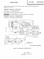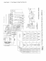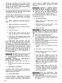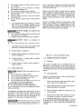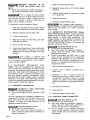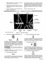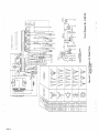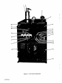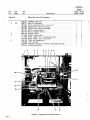
1
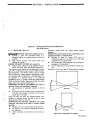
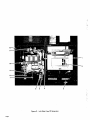
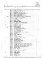
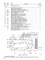
January 1983
FORM: OM-468
Effective With Serial No. JC654458
o~
MODEL
TRAILPOWER 25DA1
TRAILPOWER 25DA3
OWN ERS
MANUAL
miliEu
~ff
MILLER ELECTRIC MFG. Co.
718 S. BOUNDS ST, P.O. Box 1079
APPLETON, WI 54912 USA
ADDITIONAL COPY PRICE 75 CENTS
NWSA CODE NO. 4579
PRINTED IN U.S.A.
LIMITED WARRANTY
EFFECTIVE: JUNE 1, 1979
.
This warranty supersedes all previous MILLER warranties and is ex
clusive with no other guarantees or warranties expressed or implied.
f
LIMITED WARRANTY~Subject to the terms and conditions
hereof, Miller Electric Mfg. Co. Appleton, Wisconsin warrants
to its Distributor/Dealer that all new and unused Equipment
furnished by Miller is free from defect in workmanship and
material as of the time and place of delivery by Miller. No warranty is made by Miller with respect to engines, trade accessories or other items manufactured by others. Such
engines, frade accessories and other items are sold subject to
the warranties of their respective manufacturers, if any
All
engines are warranted by their manufacturer for one year from
date of original purchase.
As
~
warr~nty or any other duty
of any goods, the exclusive remedies
therefore shall be, at Millers option (1) repair or (2) replacement
or, where authorized in writing by Miller in appropriate cases, (3)
not
workmanship
or
mant on the
or
replacement
at
an
authorized
or
warranty claim procedures
?
be followed.
to
ANY EXPRESS WARRANTY NOT PROVIDED HEREIN AND
.
ANY
GUARANTY OR REPRESENTA-
IMPLIED WARRANTY,
?
PERFORMANCE, AND ANY REMEDY FOR
BREACH OF CONTRACT WHICH, BUT FOR THIS PROVISION,
MIGHT ARISE BY IMPLICATION, OPERATION OF LAW,
CUSTOM OF TRADE OR COURSE OF DEALING, INCLUDING
lION
material.
required to honor warranty claims on warEquipment in the event of failure resulting from a defect
within the following periods from the date of delivery of Equipment to the original user:
Miller shall be
ranted
(
repair
(4) payment of or credit for the purchase
price (less reasonable depreciation based upon actual use) upon
return of the goods at Customers risk and expense. Upon receipt
of notice of apparent defect or failure, Miller shall instruct the claiMiller service station
nozzles and nozzle insulators where failure does
result from defect in
breach of
quality
the reasonable cost of
as
including
general policy only, Miller may honor claims
original user within the foregoing periods.
In the case of Millers
specified below, Millers warranty does not apply
to components having normal useful life of less than one (1)
year, such as spot welder tips, relay and contactor points,
MILLERMATIC parts that come in contact with the welding
wire
of
matter
with respect to the
.
Except
a
submitted by the
ANY
TO
AS
IMPLIED WARRANTY OF MERCHANTABILITY OR
~
OF
FITNESS FOR PARTICULAR PURPOSE, WITH RESPECT TO
ANY AND ALL EQUIPMENT FURNISHED BY MILLER IS EX
CLUDED AND DISCLAIMED BY MILLER.
1.
Arc welders, power sources and components
2. Original main power rectifiers
(labor
.
.
3 years
4.
All other Millermatic Feeders
5.
Replacement
6.
Batteries
or
repair parts, exclusive of labor
AS
EXCEPT
1 year
only)
3. All welding guns and feeder/guns
-
1 year
WRITING,
90
.
days
EXPRESSLY
MILLER
ULTIMATE
PURCHASE
BY
that Miller is notified in
EXPERIENCED
6months
WELDING
writing within thirty (301 days
TO,
of the date of such failure.
AND
MILLERS
~.
.,~
ARE
BY
MILLER
INTENDED
IN
FOR
COMMERCIAL/INDUSTRIAL
USERS AND FOR OPERATION BY PERSONS TRAINED AND
1 year
60 days
IN
USE
THE
EQUIPMENT
AND
CONSUMER USE. MILLER
provided
PROVIDED
PRODUCTS
~,.
...~,
~
NO
RESELLER
AND
NOT
MAINTENANCE
FOR
CONSUMERS
OF
(
OR
~
WARRANTIES DO NOT EXTEND
IS
AUTHORIZED
TO
~
EXTEND
WARRANTIES TO, ANY CONSUMER.
.~
~
I
July 8, 1983
ERRATA SHEET
After this manual
appearing
was
printed, refinements
in
equipment design occurred. This sheet lists exceptions
FORM: OM-468
to
data
later in this manual.
AMENDMENT TO SECTION 3
-
INSTALLATION
Amend Section 3-4. PHASE SENSING SWITCH
Add the IMPORTANT block at the
IMPORTANT
beginning of
The Phase SENSING switch
the Section.
on
this unit is locked in the 1 PHASE
position.
______________
AMENDMENT TO SECTION 6
Amend
Figure
6-1. Circuit
-
TROUBLESHOOTING
Diagram For Single Phase Units
0~
-,
2~ OC
5]
0
0
JOE
2
OLO
0
N
0
CAUTION
~E~ER TQ
~rrEMpT
OR
NSTRUC1~O~S RE~OR~
NO
M~NTR~
TO IU5rALLO~EPaTE
~QP~.~ENT
Circuit Diagram No. B-090 359
Figure
6-1. Circuit
Diagram For Single Phase Units
~FLE COPY
RETURN TO FOW,k
E a) C
U a,
I. a,
(0
0
C)
4
a
Co 0, Co E
U 0 I Cl)
C 0) a,
I -C
a) a,
a -c Co C/)
C 4 U,
901
060-3
pu~
ON
W~J6e!(] 9~IE69~
0M
0Sl
IS
Of
1!fl3J!
0
N
U45
6
00
1
01
N
OIl
If
0
te
1I~Sl
3
1OS
.503 I0~d0
IN
InVD SNOTJ)fl015
Nol
01
1 3fl0
,e!JOS
-I1!M
IS
C
If
N
1051 iIldfOJ
OA!~3J
01.
0l4I1d7
1 101
FJ oVl
S~!Ufl
so
OS~LJd
4\IAJ IA A A A ~A A A10N41N~ .
O9J~1-lBU!S
:d~1
~
/1;*o~oo
/////
JO~
WPI6rn~J
~
-
9Jfl6!j 6uiMoI ~
9
Y
TABLE OF CONTENTS
Section No.
SECTION 1
1
1
1
-
-
-
1.
General Information And Safety
1
Receiving-HandUng
1
3.
Description
1
2-1.
-
2.
3.
2-4.
2
5.
2
-
-
2
2
2
-
-
-
6.
7.
8.
2
9.
2-10.
-
SECTION 3
3
3
3
3
3
3
-
-
-
-
-
-
Generator Reconnection
Auxiliary Power Connection
-
5
5
6
6
6
6
OPERATOR CONTROLS
Voltage Adjustment Control
Phase Sensing Switch
8
5.
Ammeters
8
6.
Voltmeter
8
Frequency Meter
Stop Control
Battery Charge Indicator Lamp
9
HourMeter
9
EtherStartingAid
Sensitivity Adjustment
OvervoltageAdjustrnentControl
9
1.
SECTiON 5
-
Engine
Ether Starting Aid
Equipment Grounding Terminal
Frequency Changeover
3.
4-2.
5
5
Pre-Start Checks
4
4.
SECTION 4
-
Fuel
4
7
3-12.
3-13.
-
3
7
-
5
Location
Spark Arrestor/Muffler Installation
Preparing New Battery For Service
Start Push Button
-
5
INSTALLTION
Safety Shutdown System
8.
3
3
9.
3-10.
3-11.
-
-
1.
2.
3 -7.
4
INTRODUCTION
2.
SECTION 2
2
-
Page
1.
2.
3.
-
9
9
9
9
SEQUENCE OF OPERATION
Starting
The
9
Engine
Engine Shutdown
-
8
10
MAINTENANCE
General
Periodic Cleaning And Inspection
10
Fuel/Water
10
Separator And Sludge Drain Plug
10
5 -4.
Air Cleaner Service
10
5
Electrical System
Servicing The Spark Arrestor
10
5
-
-
5.
6.
5-7.
5 -8.
5 -9.
SECTION 6
BrushesAndSlipRings
EtherStartingAid
Engine Speed Adjustment
-
General
6
Troubleshooting Chart
2.
6-3.
12
12
12
TROUBLESHOOTING
6-1.
-
11
Booster BatteryJump
13
13
Starting
13
No.
I
SECTION 1
INTRODUCTION
-
Single Phase
Output
25
KVA
@
KW
Volts
60
Phase
Single-Three
Output
.8 power factor
20
25
@
.8 power factor
20
120/240
120/240
3 Wire
4 Wire*
104
Amperes
Duty Cycle
100%
60
100%
Max RPM No Load
1850
1850
KVA
20
16
20
Volts
115/230
3 Wire
115/230
Amperes
Duty Cycle
87
100%
100%
Max RPM No Load
1550
1550
Hertz
KW
50
Hertz
Heigth
16
4 Wire*
50
.
Width
Dimensions
Depth
Net
Weight
Shipping
*Single.Three phase
units
are
reconnectable for other voltages listed in Figure
1-2.
Figure
1
-
1.
A.
1-1.
Specifications
carefully followed could result
or damage to this equipment.
GENERAL INFORMATION AND SAFETY
in minor
personal injury
General
signal word, iWil~];1V~h~Ij highlights instruc
special emphasis to obtain the most
efficient operation of this equipment.
A third
Information presented in this manual and on various
labels, tags, and plates on the unit pertains to equip
design, installation, operation, maintenance, and
troubleshooting which should be read, understood, and
followed for the safe and effective use of this equip
tions which need
ment
ment.
B.
The
Safety
installation,
operation,
maintenance,
and
troubleshooting
power generating equipment re
quires practices and procedures which ensure personal
safety and the safety of others. Therefore, this equip
ment is to be installed, operated, and maintained only
by qualified persons in accordance with this manual and
all applicable codes.
of
1
-
RECEIVING-HANDLING
-
Prior
installing
to
material from around
packing
equipment,
the unit and carefully inspect for any damage that may
have occurred during shipment. Any claims for loss or
damage that may have occurred in transit must be filed
by the purchaser with the carrier. A copy of the bill
of lading will be furnished by the manufacturer on re
clean all
quest if occasion
to
file claim arises.
requesting information concerning this equip
ment, it is essential that Model Description and Serial
(or Style) Numbers of the equipment be supplied.
When
1
Safety instructions specifically pertaining to this unit ap
pear throughout this manual highlighted by the signal
words I!i 1;hll~ei and CAUTION which identify
2.
this
-
3.
DESCRIPTION
supply 25 kva, 60 Hz.
primarily for use where
this unit is used
on
a
-
This generator is designed to
20 kva, 50 Hz. ac power
or
utility
standby
no
power is available. If
or
emergency basis,
___________
always consult the local electrical utility, local
different levels of hazard.
~YL1 l ~ I I~
statements include
and maintenance
procedures
or
installation, operating,
practices which if
not
carefully followed could result in serious personal injury
or loss of life.
I
statements include
and maintenance
procedures
or
installation, operating,
practices
or state
codes, and the latest issue of the National Electrical
Code for proper installation procedures.
which if not
WARNING
ELECTRIC SHOCK
can
kill.
__________
Do
not
connect
to
any
electrical
distribution
system normally supplied by utility power unless a
proper transfer switch and grounding procedure
are
employed.
OM.468
Page
1
All units
are shipped set up to provide the type of power
output specified by the customer. If no specific output
request is made, single phase units are shipped set up to
supply 60 Hz. single phase output and single-three
phase units are shipped set up to supply 120/240 volts,
60 Hz., three phase output (Series Delta generator con
nection). Both single phase and single-three phase
generators
driven
are
Deutz diesel
by
a
three
cylinder, air-cooled,
Equipment that must be operated on an electrical supp
ly that has precise frequency tolerance or a pure
sinisoidal
wave
form should not be connected to the
output of this generator.
Equipment that is sensitive
to
frequency
ow
engine.
Single-three phase generators are reconnectable in
parallel or series wye, or parallel, series, or double delta
connection with available voltages listed on Figure 1-2.
/~/
/
/1//GENERATOR
~
G
f
89
120/206
3
50
86
27/220
3
60
60
I
3
60
110/190
3
50
58
15/200
3
50
56
20/208
3
50
39/240
33
27/220
Y2
110
~
-J
50
35
240/416
3
80
33
254/440
3
60
30
277/480
3
80
30
220
380
3
50
15
1
~
112
LO
~
~
3
13
.~rai
1 ~..
17
~
61
29
230/400
3
50
240/418
3
50
26
254/440
~
~
80
20/240
3
40
3
~,
~
76
~TI2
~
~
LO
~T6
1~
50
L3~-
~
~L0
~T7
~
16
50
~
T~
12
,J,
120/240
3
50
1
60
15
14
15
110
111
112
L2
LO
LI
19
73
75
18
72
74
77
TI
110
III
112
LI
112
19,(4~~1T1
I
48
17
L3
III
3
II
V J~ V I J ~
rg~
W
15/230
18
12
~
0
50
12
L2
15
17
4
110/220
19
L3
Ll
13
53
OIAGRAM
L3
U1
26
WIRING
VVV~.
19
13
TI
/
GENERATOR CONNECTION
L2
LI
5
TO
LOAO
CONNECTION
p~ ~ /
13
~II
18
19
12
Tb
15
18
TI
112
14
17
yVyVyy
L2
04
20/240
16
--~
~L0
-J
SI
110/220
I
50
~
15
12
19
~
0
La
87
15/230
I
50
~
~
~
33
120/240
206
120
I
50
I
50
~
174
115
I
50
~
~
<
I
~
1
50
fl~
16
110
13
TI
75
12
14
TI
112
VVVV~
.2
LO
LI
a.
12
14
18
ItO
13
15
19
13
~19
~
~1I1
33
~T8
T4JTIO
III
II
16
17
112
~K
(L ~ ~T1,T?
~
12
L2
Figure 1-2. Generator Connection Diagrams
Output Specifications
Page 2
15
LI
ItO
20
19
L2
16
<
82
167
T7
18
~
I
~
TI~O
50
I
LI
13~
or
voltage
be disconnected from this generator when the
generator is started or stopped.
must
And
SECTION 2
Figure
2-1.
-
in
open
well
ventilated
can
areas
kill.
or
if
vent engine exhaust outside the
building.
Keep engine exhaust vent outlet away from
building air in takes.
operated indoors
ENGINE EXHAUST SPARKS can cause fire.
Exhaust spark arrestor must be installed in accor
dance with local, state, and federal regulations.
The
engine exhaust system
on
And Base Moun
Exceeding
damage.
1fj~ll~Ic~ ENGINE EXHAUST GASES
Operate
Drawing
Layout
Hole
LOCATION (Figure 2-1)
1.
INSTALLATION
Dimensional
ting
2
-
this generator is equip
these
limits
can
cause
severe
engine
RESTRICTED AIR FLOW causes overheating and
possible damage to internal parts~
least 24 inches (610 mm) of
at
unrestricted space on all sides of unit and keep
underside free of obstructions.
Do not p/ace any filtering device over the intake air
Maintain
passages of this generator.
Do not install this unit in a permanent indoor loca
tion.
Warranty
is void if any type of
filtering
device is used.
ped with a combination spark arrestor/muffler as stan
dard equipment. This device carries U.S.D.A. Forest
Service Approval. A spark arrestor, maintained in effec
tive working order, is mandatory if this generator is to
be operated in a National Forest or on California
Grasslands, brush, or forest covered land (see Section
4442 of California Public Resources Code). For other
areas, check your state and local laws.
IMPROPER LIFTING OF EQUIPMENT can result in
personal injury and equipment damage.
equipment of adequate capacity
Use
to lift the
unit.
If
using lift forks to handle this unit, be sure the lift
are long enough to extend out of the op
posite side of the base.
Using lift forks too short will expose internal com
ponents to damage should the tips of the lift forks
forks
penetrate the bottom of the unit.
OPERATION ON LINLEVEL SURFACE
improper lubrication and result
damage.
Operate unit
in
an
in
approximately
level
cause
engine
position.
2-2 for maximum allowable tilt for pro
See
Figure
per
operation.
Check crankcase oil level with unit
face.
can
severe
TA.046 152
on a
level
sur
Figure 2-2. Allowable
Tilt Angles
OM-468
Page
3
This genertor is provided with a lifting eye for moving
the unit and mounting holes in the base rails for secur
ing the unit in a permanent location, or to a trailer, or
transport vehicle. Figure 2-1 gives overall dimensions
and base mounting hole layout.
running. However,
power
mounting location should allow sufficient
room to
open the side doors and remove the cover and
for maintenance and repair functions.
panels
Wi~II~Ic~ CHARGING
cause
A FROZEN BATTERY
the battery to explode and result in
serious personal injury or damage to equipment.
I
Check the state of the e/ctro/yte solution and
allow battery to warm up to 60F (16C) before
charging
The service life and operating efficiency of this unit are
reduced when the unit is subjected to high levels of
dust,
dirt, moisture, corrosive
vapors,
and
-
1.
Raise the left side door and
secure
Remove
for
if
electrolyte is frozen
vent caps
charging
slushy.
2-3C, Steps 7-9
or
and refer to Section
instructions.
extreme
C.
Dry Charged Battery
INSTALLA
1.
Obtain
open.
2.
heat.
2
2. SPARK ARRESTOR/MUFFLER
TION
battery fails to supply enough
engine, the battery will require
recharging.
can
The
if the
crank the
to
battery grade (1 .265 specific gravity)
electrolyte solution.
Remove battery from unit and place
or other suitable surface.
on
a
level
worktable
2.
Install the exhaust pipe in the exhaust
the manifold.
flange
on
3.
Remove vent caps.
I~h1;I~Il~(e~ BATTERY ACID
3.
Close the side door.
4.
Install the spark arrestor/muffler onto the ex
haust pipe and secure with the muffler clamp.
can
burns eyes and
and
destroy clothing and other materials;
BATTERY GASES can explode and shatter the bat
skin
tery.
Wear correct eye and
body protection.
spill or splash battery fluid.
Do not apply pressure to walls of filled battery-use
battery carrier or place hands on opposite corners
when llfting battery.
Keep sparks, flames, cigarettes, and other ignition
Do not
5.
Install weather cap onto spark arrestor/muffler
that exhaust is discharged toward side of unit
so
as
shown in
Figure
2-1.
3. PREPARING NEW BATTERY FOR SER
This unit may be equipped with a maintenanceVICE
free battery, a conventional wet charged battery, or a
dry charged battery. Maintenance-free batteries do not
2
-
sources
away from batteries.
-
have conventional vent caps since they do not require
the addition of water during normal service. Once the
battery type is determined, read the following WARN
ING and proceed to the appropriate section: A.
Maintenance-Free Battery; B. Wet Charged Battery; C.
Dry Charged Battery.
enough ventilation to keep battery
building up during activation.
Use
gases from
4.
Fill battery cells
trolyte.
to
5.
Allow
stand for 20 minutes.
6.
battery
Recheck
to
top of separators with elec
electrolyte level
and add if necessary to
fill to top of separators.
~ BATTERY ACID
can
burn eyes and
destroy clothing and other material.
Wear correct eye and body protection when work
ing with batteries.
ABNORMAL VOLTAGE can cause damage to
engine electrical components.
Do not operate engine without the battery con
skin and
7.
center
nected.
Do not disconnect the
battery while
the
engine
electrolyte temperature in one of the
For
a battery thermometer.
each 10F (6C) increment above 80F (27C),
a correction factor of 0.004 specific gravity must
be added to the specific gravity reading taken in
Step 8. For each 10F (6C) increment below
80F (27C), 0.004 must be subtracted from the
reading taken in Step 8.
Check
is
cells with
running.
8.
Maintenance-Free Battery
A.
To place this battery in service connect the negative (-)
battery cable to the negative battery terminal. No other
preparation should
be
Check the specific gravity of each cell with a
hydrometer. (Draw in and expel the electrolyte
two or three times from the first cell to be tested
to
adjust
the temperature of the
that of the
Wet
Charged Battery
Connect the negative (-) battery cable to the negative
on the battery. If the battery has enough power
Page
4
the
engine,
it will
charge
the
below in addition to those
WARNING statements.
terminal
to start
to
required.
L~k1;li~Il~~c-r Follow
B.
hydrometer
electrolyte.)
up while the
engine is
Use enough ventilation
building up during and
tery charging.
precautionary steps
given in the previous
to keep battery gases from
for several hours after bat
off before
charger
Turn battery
tion
making
connec
battery.
to
or move connections on battery
charger is on.
over battery when charging.
Be sure battery charger connections to batter, are
clean and tight.
Keep vent caps in place and cover top of battery
with damp cloth.
Be sure battery charger output matches battery
voltage.
while batter,
Do not lean
If
a
corrected specific
(27C)
80F
caps and
is not
gravity reading
of 1 .260 at
obained, replace the vent
battery following the bat
the
recharge
tery charger manufacturers
~
engine at the factory and could
rough engine running if not properly diluted with
cause
Do not touch
9.
side of fuel tank and
instructions.
BATTERY GASES
can
a
full tank of fresh fuel.
Keep the fuel tank filled tO ensure that the injector
system receives an adequate supply of fuel. If the fuel
tank is allowed to empty, air will enter the system caus
ing starting problems. The Engine Manufacturers
Manual outlines procedures for air venting the fuel
system.
Figure 2-3 illustrates typical fuel consumption under
specific load conditions. Fuel consumption will vary
from one engine to another. Different brands of fuel,
operating conditions, condition of the engine, etc., will
affect the fuel consumption of this engine.
explode and
shatter the battery.
Turn the battery
charger off before disconnecting
charger from the battery.
Recheck electrolyte level and add if necessary.
the
10.
ACID
BATTERY
CAUTION
is
corrosive
to
metals.
electrolyte into
Do not pour
Thoroughly
11.
metal sink
a
drain.
or
rinse with water and mutilate empty
electrolyte containers before discarding.
12.
Reinstall battery in generator.
13.
Replace battery holddown and tighten securely.
Do not overtighten.
Connect positive 1)
(+1 battery terminal.
14.
battery cable
to
positive
Figure 2-3. Fuel Consumption Chart
2
-
ENGINE PRE-START CHECKS
5.
Oil Level
A.
Connect negative (-I battery cable to
battery terminal.
1 5.
2
-
4.
negative I-)
engine is shipped with its crankcase filled with
break-in oil. If the oil level is not up to the full mark on
the dipstick, add oil according to the recommendations
in the Engine Manufacturers Manual before starting the
The
FUEL (Figure 2-3)
ENGINE FUEL
L~h1lI~c~
can
cause
fire
engine.
or
ex
plosion.
B.
Do not
Do not
Do
not
spill fuel;
if
spilled, wipe up.
fill fuel tank if engine is hot or running.
refuel near sparks or open flame.
Perform the
before
Do not smoke while refueling.
Do not fill fuel tank to top; a//ow 3/4 inch (19 mm)
Do not
use
gasoline
to fuel
a
pump and
diesel engine.
damage the injector
in
Engine Manufacturers
See the Engine
open position.
Manual for fuel recommendations. The
the
capacity of the fuel
tank is 23
4.
preventative
was
added
to in-
Manual).
impeller for obstructions
Ensure that all sheet metal
and
2
time. Rust and corrosion
Check the blower
free movement.
gallons (87 liters).
II ~i I ~Ls] t f~1 ~ 1 ~ Fill fuel tank up to 3/4 in (19 mm)
from top with fresh fuel before starting engine the first
cooling system
Check the blower belt for proper tension (see the
3.
tank,
the air
2.
injectors.
Manufacturers
on
Check the engine air intake and exhaust open
ings to ensure no blockage exists.
This generator is shipped with a small amount of fuel in
the fuel tank, and fuel shut-off valve, located under the
fuel
following checks
operating the engine:
1.
from fuel to tank top for expansion.
USE OF GASOLINE will damage engine.
Lack of lubrication in the fuel will
Cooling System
panels
are
and
cowlings, shrouds,
properly in place
and secure.
6. ETHER STARTING AID (Optional)
This unit
is shipped without the ether cylinder. Before this device
is operational, an ether cylinder must be obtained and
-
-
installed.
OM-468 Page 5
HANDLING
OR
EX
IMPROPER
ETHER can seriously harm your
1.
Open and
2.
Reposition jumper links
frequency.
on
3.
Readjust engine speed
2-11, Section 5-9.
as
that the nozzle on the ether cylinder and the fit
ting into which the ether cylinder is inserted are both
4.
Close right side door
If dirt is present in either of these areas,
system may be rendered inoperative.
5.
Reconnect
WARMNG:
____
POSURE
TO
health.
Pa//ow the manufacturers safety instructions
the cylinder when handling ether components.
I
1Wi1 ~1 I f~ I ~ Prior to
the ether
installing
on
cylinder,
right
secure
side door.
2T to match desired
instructed in
Steps
ensure
clean.
To install ether
cylinder, proceed
as
the
follows:
negative battery
changing output frequency, it
readjust the VOL TAGE ADJUST
II~I~s1;~f~If After
may be necessary to
1.
Open right
side
panel and
ether start components
2.
secure
on center
open. Identify
frame upright.
Loosen
4.
Place
new
cylinder
onto valve
Secure cylinder with clamp.
6.
Using
a
fitting,
and rotate
liquid soap solution, check all ether
system connections for leaks. If
escaping
gas will
produce
-
9.
GENERATOR
generators
secure.
5.
output voltage.
a
RECONNECTiON
Three Phase Generators
cylinder clamp.
clockwise until
MENT control (see Section 3-3) to obtain the desired
2
Remove protective cap from ether valve.
3.
cable.
start
(Single
Only)
Single-Three Phase
be operated in series or parallel wye or
can
-
series, parallel, or double delta connections. The
voltages available for each generator connection and
output frequency (see Figure 6-2) and set by the
VOLTAGE ADJUSTMENT control. To
generator, proceed as follows:
reconnect
~ ELECTRIC SHOCK
kill.
can
the
Do not touch live electrical parts.
Shut down engine and disconnect negative 1-)
battery cable from battery before attempting
1
leak exists,
bubbles in the soap
solution.
generator reconnection.
IMPORTANT After
installing
or
replacing
Ground in accordance with NEC, state, or local
codes; connect grounding lead to appropriate
generator leads depending on output load lead
ether
______________
do not use or test ether start system for at/east
10 to 15 minutes to allow particles in fuel to settle to
prevent atomizer plugging.
cylinder,
connection. Be
nected to the
sure
that
a
proper
ground is
con
terminal
on
leads in connection box
on
equipment grounding
the generator frame.
2
-
7.
EQUIPMENT
MINAL
GROUNDING
TER
This unit is equipped with a grounding ter
minal, located on the left base rail, for frame and case
grounding. For detailed grounding instructions consult
your local or state codes or the latest issue of the Na
tional Electrical Code. If additional information regar
ding your particular operating circumstances and/or
grounding requirements is needed, consult a qualified
electrician or your dealer. After determining the extent
to which any grounding requirements apply to your par
tricular situation, follow them explicitly.
2
-
8.
1.
-
2.
Open and
Locate T
stator
3.
and L
door.
barrel.
Reconnect
T
and
L
leads
to
obtain the
desired generator output. Refer to Figure 1 -2. If
the generator reconnection results in a phase
change, the position of the Phase SENSING
switch may also have to be changed (see Section
3-4).
FREQUENCY CHANGEOVER
EXCESSIVELY
HIGH
EXCITATION
CURRENT can damage generator.
Be sure engine speed for 50 Hz. operation is 1550
4.
Reinsulate all connections.
5.
Close side door.
6.
Reconnect
rpm.
This unit is equipped with a frequency changeover ter
minal strip 2T, located in the connection box on the
stator frame behind the right side door. If it becomes
necessary to change the output frequency of the
generator proceed
as
follows:
IT~IT~II~(c~ ELECTRIC SHOCK
can
kill.
Do not touch live electrical parts.
Shut down engine and disconnect
negative (-)
battery cable from battery before attempting fre
quency changeover.
Page 6
right side
secure
negative battery
cable.
2-10. AUXILIARY POWER CONNECTION
LkYL1;1~ll~e~
ELECTRIC SHOCK
can
kill.
Do not touch live electrical parts.
Shut down engine and disconnect
negative (-)
battery cable from battery before attempting to
connect the load circuit to the generator.
Do not connect to any electrical distribution
system normally supplied by utility power unless a
proper transfer switch and grounding procedure
are
employed.
1.
2.
3.
Select desired lead entry location, and
knockout blank from junction box.
remove
Install proper connector (not supplied) into open
ing and route load leads through connector into
junction box.
the 100 ampere circuit
Connect the load leads
to
breaker in the
box.
junction
On
Single-Three phase units,
the generator output
located behind the left side door. Connect the
load leads directly to the generator output leads or in
leads
SECTION 3
-
are
stall desired customer
connecting
supplied junction box
or
panel for
the generator output leads and the load cir
cuit.
Reconnect
negative battery
cable.
OPERATOR CONTROLS
Ammeters
Hour Meter
Stop control
/
Oil Pressure
Switch/Gauge
/
Frequency
Meter
Engine Temperature
~
Switch/Gauge
I
!Ba~e~
Overvoltage
Safety Shutdown
Condition
Switch
Warning
Lamp
Light
Single
Phase Model Shown
Figure
3
1.
-
SAFETY SHUTDOWN SYSTEM
3-1.
Front Panel Controls
(Figure 3-1)
B.
Engine Temperature Switch/Gauge
The ENGINE TEMPERATURE switch/gauge indicates
crankcase oil temperature. If oil temperature rises to an
unsafe level the
The SAFETY SHUTDOWN switch must be depressed
and held closed until the engine starts. If oil pressure or
oil temperature reach unsafe levels, or if the overvoltage
device is actuated, the Safety Shutdown System stops
the
engine. Do
not
attempt
to
C.
to 1-1/2 minutes.
The
engine
engine is
will falter before
1
coming
complete stop.
to a
This switch is protected by an in-line fuse. Should this
engine would not start.
fuse open, the
A.
Oil Pressure
engine.
Vfi
operate the engine until
The shut-off time for the
down the
Overvoltage Condition Light
the trouble is remedied.
~
switch/gauge shuts
The
OVERVOLTAGE CONDITION light lites up in
dicating an immediate interruption of generator output
caused by an overvoltage condition. The light remains
on until the SAFETY SHUTDOWN switch is depressed.
3
-
2. START PUSH BUTTON
(Figure 3-1)
Switch/Gauge
push button is provided on the front panel for
starting the engine. Pressing the START push button
will engage the starter motor and start the engine. Once
the engine has started, release the START button.
A START
The OIL PRESSURE
switch/gauge
indicates lubrication
system pressure. If oil pressure drops to
the
an
switch/gauge shuts down the engine.
unsafe level
OM-468 Page 7
CAUTION
REENGAGING
STARTER
MOTOR
_________
while
flywheel is rotating
can
damage starting
components.
Do
reengage starter motor until starter
and flywheel have stopped rotating.
I
3
3.
-
not
VOLTAGE
ADJUSTMENT
pinion
120/240 volt load is connected the ammeter in
dicating the lower current is reading the 240 volt cur
rent. The ammeter indicating the high current is reading
If
a
the combined 120 and 240 volt currents. The difference
between the two ammeter readings is the 120 volt cur
example: if ammeter Li reads 80 amperes and
L2 reads 30 amperes, the 240 volt load is drawing 30
amperes, the combined 120 and 240 volt load is draw
rent. For
CONTROL
(Figure 3-1)
ing
80 amperes, and the difference between the two
50) is the 120 volt load cur
readings (80-30
meter
=
rent.
V
B.
The VOLTAGE ADJUSTMENT control fine adjusts out
put voltage. Loosen the control brake and rotate the
control shaft clockwise to increase output voltage/load
voltage.
reading
Accurate
the
ac
voltage adjustment
voltmeter.
Retighten
can
be made
by
brake.
Single-Three Phase Units
This unit is equipped with three ammeters, labeled Li,
L2, and L3.
Ammeters, Li and L2, enable the operator
to read the
separate 120 volts single phase
loads; or either meter can be read for a 240 volts single
phase load.
through
current
two
Overvoltage
Adjustment
If
120/240 volt load is connected the ammeter in
dicating the lower current is reading the 240 volt cur
rent. The ammeter indicating the higher current is
a
the combined 120 and 240 volt currents. The
reading
Phase
difference between the two ammeter readings is the
120 volt current. For example: if ammeter Li reads 80
Sensin
Switch
amperes and L2 reads 30 amperes, the 240 volt load is
drawing 30 amperes, the combined 120 and 240 volt
Sensitivity
Adjustment
load is
drawing 80 amperes, and
readings (80-30
the two meter
the difference between
=
50) is the 120 volt
load current.
240 volts
the
Figure 3-2. Voltage Regulator Panel
3
4.
-
3-2)
-
voltage regulator panel
behind the left side door. The
Phase SENSING switch must be placed in the 1 PHASE
position when single phase power is used and in the 3
PHASE position when three phase or a combination of
three phase and
switch
positions
CAUTION:
PHASE
3
VOLTAGE
-
IMBALANCES
equipment damage.
one
3
-
6.
VOLTMETER
one
the im
(Figure 3-1)
V
regulated ac voltage output
of the generator and the load voltage. If two separate
120 volts loads are connected to the generator, read
half of the voltmeter indication for each load.
~ On
connected
(Figure 3-1)
Single Phase Units
This unit is equipped with two ammeters, labeled Li
and L2, which enables the operator to read the current
through two separate 1 20 volts loads; or either meter
can be read for a 240 volts load.
8
value. If
different from the
balance.
single phase units,
the voltmeter is
series-connected 120 volt power
windings. If a load is connected across one of the 120
volt windings the voltmeter still reads the seriesconnected voltage (240 volts). To obtain the voltage
across
across
voltage
across two
the
dication.
reads the
Page
any of
phase
A
A
same
on
three-phase
reading
phase is loaded differently causing
PHA SE position.
AMMETERS
be read
balanced
a current
power with the Phase SENSING switch in the 1
5.
current can
Under
The voltmeter indicates the
Do not attempt to draw unbalanced three
I
indicates
single phase power is used. Changing
may require readjustment of the
VOLTAGE ADJUSTMENT control.
could result in
ammeter
others,
ammeters.
all ammeters will read the
loading,
PHASE
SENSING
SWITCH
(Figure
The Phase SENSING switch is located on the
three-phase
ac
three
single load read one-half the voltmeter in
single-three phase units, the voltmeter
voltage across one phase (L 1 -L2). The voltage
On
the
other two phases is –2% of the L 1-L2
if the Phase SENSING switch is in the 3 PHA SE
position.
3 -7.
FREQUENCY METER
(Figure 3-1)
IMPORTANT The measured quantity of ether is
sprayed into the engine when this switch is re/eased.
Depressing the switch does not spray the ether into the
engine but rather fills the valve chamber.
___________
Hz
The
Frequency Meter indicates the output frequency
from 45
to
SENSITIVITY
3-12.
65 Hertz.
(Figure
ADJUSTMENT
A SENSITIVITY ADJUSTMENT control is pro
vided on the voltage regulator panel behind the left side
3-2)
-
door
eliminate
to
voltmeter
instability
when
the
VOLTAGE ADJUSTMENT control is set at low voltage
adjustment conditions. Loosen the control brake and
3
8. STOP
CONTROL (Figure 3-1)
The PULL
OUT TO STOP ENGINE control, when pulled fully out,
cuts off the flow of fuel at the fuel injection pump,
-
-
thereby stopping the engine. This control is springloaded and must be held fully out until the engine is
completely stopped.
3
-
9.
BATTERY
CHARGE
INDICATOR
LAMP
(Figure 3-1)
rotate the SENSITIVITY ADJUSTMENT control only
enough to eliminate meter instability. Over adjustment
can
adversely affect voltage regulation. Retighten
brake.
3-13. OVERVOLTAGE ADJUSTMENT CONTROL
(Figure 3-2)
II~I~.1;If~1 f The OVERVOLTAGE ADJUSTMENT
control located
i: ~i
the left side
on
the
voltage regulator panel behind
door, is factory
set
and
requires readjust
only after component failure
regulator board.
rnent
The AMPS
warning lamp will be illuminated
engine battery charge current is not flowing.
3-10.
HOUR METER
when the
on
the
voltage
The overvoltage circuitry actuates the Safety Shutdown
system if the upper limit for load circuit voltage is ex
(Figure 3-1)
ceeded
by the generator. To make overvoltage circuit
adjustment proceed as follows:
t
1.
This unit is equipped with
hour meter. The meter
registers the total hours of engine operation. This infor
mation is useful for routine maintenance on the engine.
2.
3-11.
3.
Start the
ETHER STARTiNG AID
Loosen the brake and rotate the OVERVOLTAGE
ADJUSTMENT control fully counterclockwise.
(Optional) The cold
starting components which are incorporated
into this generator provide a means of supplying a
premeasured portion of ether into the manifold. The
amount of ether supplied should be sufficient to permit
easy engine starting under cold weather conditions.
-
weather
4.
Loosen the brake and rotate the VOLTAGE AD
JUSTMENT control to a 15% value above
desired operating voltage level upper limit for the
load circuit.
Rotate
control
Actuating the ETHER STARTING AID switch, located
to the left of the START push button, for 1 second
while cranking the engine will provide the proper
amount
tion
of ether
to
the manifold. This control will func
MOVING PARTS
injury; IMPROPER AIR FLOW
can
can
-
5.
cause
result in
serious
operating.
Keep clear of moving parts.
Warranty is void if the generator is operated with
portion of the outer enclosure open or removed.
to start
as
sure
the
and
on
the
engine
shuts
down.
brake.
Start the engine and readjust Voltage Adjust
ment control for desired output voltage.
4
1.
-
STARTING THE ENGINE
1.
Press the START push button (see SECTION
3-1) and the SAFETY SHUTDOWN switch (see
Section 3-2) and actuate the ETHER STARTING
AID
switch,
if
applicable, for
1
second
and
release (see Section 3-1 1).
any
the unit has been installed
_____
prepared
comes
damage
internal parts; EXPOSURE TO WEATHER can
shorten the life of internal components.
Keep all covers and panels in place while
IMPORTANT: Be
the
OVERVOLTAGE ADJUSTMENT
until the OVERVOLTAGE CONDITION
SEQUENCE OF OPERATION
to
ting
light
Tighten
only while cranking the engine.
SECTION 4
and
engine (see Section 4-1).
an
instructed in Section 2 before attemp
2.
As
soon
the engine starts, release the
as
START push button and allow the engine to
warm up for approximately three minutes with
no
power load
applied.
engine.
OM-468 Page 9
3.
Loosen the brake and rotate the VOLTAGE AD
JUSTMENT control to obtain the desired voltage
2.
Allow the engine to run for a few minutes to per
mit the internal engine temperature to equalize.
(see Section 3-5). Tighten brake.
Increase
the
operating for
4
2.
-
3.
HOT
WARNING
severe
engine
period or
has
been
at full load.
fully Out and hold it in this
position until the engine stops completely.
ENGINE
PARTS
can
-
Do not allow fuel to drain onto the
cause
ing
protective gloves and clothing when work
on a
Keep
hot
engine.
can cause
c/ear of
serious
injury.
moving parts.
engine and disconnect negative (-)
Shut down the
battery cable from battery before internally
specting
engine
or
other
components.
MOVING PARTS
or
in
servicing.
1. GENERAL
The service life of this generator
operating efficiency maintained
under normal conditions by following the routine ser
vice and workshop maintenance procedures outlined in
be
MAINTENANCE
burns.
Wear
-
the
Pull the STOP control
Remove the power load from the unit.
SECTION 5
can
if
extended
ENGINE SHUTDOWN
1.
5
time
an
prolonged
-
and
this section and in the
Engine Manufacturers Manual
(F3L912 Engine). Where operating conditions are
severe, more frequent attention must be given to all
routine service categories; however a special effort
must be made to maintain clean
Do not spill fuel; if spilled, wipe up.
The fuel/water separator, located below the fuel tank
on the right side of the generator, provided to drain off
water
from the fuel tank. Before
the first time each
starting
day, open the petcock
the
on
engine
for
the bottom
of the separator and drain the water into a metal
tainer. Close the petcock at the first signs of fuel.
con
The fuel/water separator should be changed every 125
hours of operation or 4 months, whichever occurs first.
A
sludge drain plug is provided on the bottom of the
fuel tank to drain off sediment from the fuel tank. Once
a week, drain the sludge into a metal container. If ex
tremely dirty fuel is encountered,
ing will be necessary.
a more
frequent drain
internal and external
engine surfaces.
5 -4.
CLEANER SERVICE (Figure 5-1)
The
one of the most important parts of the
engine from the standpoint of engine life. An engine
consumes several thousand cubic feet of air per hour
when operating. If dirty air gets into the engine, it can
AIR
-
air cleaner is
5 -2.
PERIODIC
CLEANING
AND
IN
SPECITON
A schedule for cleaning and inspection
should be set up, based on the type and conditions of
-
service,
to
include the
following:
a set of piston rings within a few operating
Every 50 hours or less depending on conditions,
empty the dust cup and inspect the element.
wear out
hours.
Keep the inside of the unit clean by blowing
the unit
out
with clean, dry compressed air.
II ~A I ~s] I f..i ~ I ~ A
Examine all intake and
sure
that
free of
they
foreign
are
discharge air openings,
and
en
not blocked in any manner and are
Check for fluid leaks
indicating loose
oil
or
fuel
loose connections and clean oil
leaks oft of engine surfaces.
or
engine exhaust.
When it becomes necessary to service the air cleaner in
the field, follow the steps in Figure 5-1. It is recom
mended that a spare element always be kept on hand
for replacement. New elements
distributor.
or
fuel
IMPORTANT
Periodically inspect the labels on this
precautionary labels must be main
c/early readable state and replaced when
legibility.
tained in
a
are
available from your
L~I1I.1~ DIRTY AIR can damage engine.
Do not operate engine with dirty air cleaner ele
ment in place.
Do not operate
_______________
unit for
dirty air cleaner element is usually
loss of power and black smoke in the
connec
Tighten
spills
a
matter.
Examine blower impeller to be sure that the blades do
not have an obstruction of any kind lodged between
them. The blower must be able to turn freely.
tions.
accompanied by
All
necessary. See the Parts List for part number of precau
in
5
-
5.
engine without
air
cleaner element
p/ace.
ELECTRICAL SYSTEM
tionary labels.
A.
5
3.
FUEL/WATER SEPARATOR AND SLUDGE
DRAIN PLUG
-
WARNING:
ENGINE FUEL
can
cause
fire
or
ex
plosion.
Do not drain fuel tank while
Do not smoke while
Page 10
engine
handling fuel.
is
running.
Cables And
Wiring
Check interconnecting wiring and connections for
tightness and flaws. Check the insulation for breaks or
other signs of damage. Repair or replace cables or wir
ing as necessary.
I
B.
6. SERVICING
THE
AR
SPARK
RESTOR
Internal combustion engines operating in a
highly combustible environment are a common fire
hazard. Glowing carbon particles blown Out with the ex
5
Battery
-
-
WARNiNG
BATTERY ACID
burn eyes and
and other material.
___________
skin and
destroy clothing
can
haust
Wear correct eye and body protection.
Periodically inspect the battery for loose connections,
cables, corrosion, cracked case or cover,
holddowns, and loose or deformed terminal
posts.
Easy
Steps:
Important
1.
Stop engine.
2.
Wipe off
arrestor should be
spark
hours
or
before
opening
before
Remove
4.
Remove element.
1.
Dont
cover,
attempt
cleaner with
to
service air
leave open air cleaner
blowing dust while
Dont
3.
engine running,
exposed
blow out the inside of the
8.
Replace
5.
For Donaclone air cleaners
cover.
installed
If sir cleaner is
Compressed
Air
or
Washing.
a
sure
positioned
is
Clean element by one of the
following methods:
better
is recommended
horizontally
into the
point
when exhaust soot has
lodged
in
fine pores of the filter media.
Use Donaldson D-1400 detergent
for
removing
a
special additive
soot
you will blow dust
engine.
up.
and must be used
job
or
cover
lit any) correctly
cover
that dust cup
so arrows
which contains
Compressed air
blow out Donaclone tube
and inner
mounted, be
Re-Use
Reinstall element.
section without element,
Replace
cover,
4.
Clean
7.
dont
to
air cleaner with compressed air.
Elements
F or
operating
use.
you clean element.
How To
every 1000
season.
6.
3.
Dont
materials.
ignite
Inspect new element and
all gaskets for shipping damage
air cleaner.
2.
inspected
three times per
5. Wipe out element chamber
with clean, damp cloth.
cover
heat to
no
The carbon trap should be serviced weekly or every 50
operating hours, whichever occurs first. The entire
On units with conventional batteries frequently check
the electrolyte level. Add clean mineral-free or distilled
water to bring the elctrolyte in each cell up to the level
indicator
Follow
These
sufficient
retain
practical spark arresting device will stop all
sparks, this device will minimize fire hazards by remov
ing and trapping most solid particles provided that it is
properly maintained.
defective
loose
can
While
and carbon.
(When cleaning Cyclopac
elements, do not remove plastic
fin assembly
back-flowing with
-
compressed
remove
fin
air
or
washing
will
dust from beneath the
assembly.)
when element will be re-used
immediately
element
re-use.
because
must
a
However,
Replace element after 6 cleanings
annually, whichever
washed
be dried before
washing
does
or
occurs
first.
compressed Air
Washing
through element in
the direction opposite to normal
air flow through the element.
1.
water
Move nozzle up and down while
instructions,
rotating element. Keep nozzle
at least one inch from pleated
2.
Direct air
paper. Maximum air pressure
-
100 P.5.1.
Inspection
Soak element 15 minutes
more
in Donaldson D-1400 and
solution. See carton for full
Rinse until
IMaximum
40 PSI.)
Place
bright light
inside element
and rotate element
slowly.
If
any rupture, holes or damaged
gaskets are discovered replace.
.
water
is clear
water pressure
3. Air-dry or use warm
Do not
air. max. 160F.
compressed
Figure 5-1.
or
air
or
flowing
use
light bulbs.
Air Cleaner Service
OM-468 Page 11
A.
as part of the emery will embed itself into the
and in turn destroy the carbon brushes.
Visually examine the outside of the device for
holes, cracks, or metal corrosion.
1.
Replace the brushes if they become chipped
With the
look inside the
engine stopped,
arrestor outlet tube with a
flashlight
Visually examine
source.
outlet tube for metal
or
the
or
spark
other
light
and
the
vanes
weld failure. The
vanes
be
firmly attached to the inlet tube and the
outlet tube must be completely intact (this is an
important factor in maintaining spark arresting
efficiency).
must
3.
Check the
mounting clamp to ensure that the
is securely mounted. Replace the
arrestor if inspection reveals any signs of
spark
spark
arrestor
failure.
B.
The Carbon
Servicing
Trap
EXHAUST SPARKS can cause fire.
Clean spark arrestor/muffler in a non-combustible
environment.
LTk!~1~h~lIk1(C~
S
left.
5
8.
ETHER
STARTING
Stop
the
and allow the exhaust system to
engine
cool.
AID
The
(Optional)
starting aid system is
contained in a replaceable cylinder located behind the
right side access door on the center portion of the
frame. No indicator is provided to show the amount of
ether left in the cylinder; therefore it is recommended
that a spare cylinder be kept on hand. Generally, the
ether cylinder is empty when the engine fails to start in
cold weather while utilizing the cold weather starting
system. To check if the cylinder is empty, remove the
cylinder and shake it. If a slushing sound is not heard,
the ether cylinder is empty. The ether cylinder can also
be weighed to check for contents, 33 ounces is the
weight of the cylinder when empty. To replace the ether
cylinder, loosen the clamp which secures the cylinder to
the mounting bracket, and rotate the ether cylinder in a
-
-
ether used in the cold weather
counterclockwise direction.
II ~ I ~s] ~I fe.! ~ I ~ Prior
1.
broken
or
if less than 1/2 inch (12.7 mm) of brush material is
or
2.
rings
cloth
Inspection
cylinder,
and the
ensure
fitting
to
the
installing
that the nozzle
into which the ether
ether
new
the ether
on
cylinder
cylinder is inserted
both clean. If dirt is present in either of these areas
the system may be rendered inoperative. Also check for
are
2.
Remove the cleanout
spark
ed
arrestor
over
with
the
screwdriver
or
a
hole,
plug
from the side of the
wrench. If
break
a Crust
it
has form
loose
with
a
similar tool.
HOT EXHAUST can cause severe
burns; HOT CARBON PARTICLES DISCHARGED
FROM CLEANOUT HOLE can burn eyes and skin.
CAUTION:
_____
Wear correct eye and
S
body protection.
damage
Start the
the
engine
cleanout
to blow
hole.
If
discharge, momentarily
collected particles Out
particles are slow to
cover
the end of the
ex
4.
Stop
the
engine.
cleanout plug.
Replace
and
secure
the
which is located
the in
on
IMPORTANT After
installing
or
replacing
ether
_______________
cylinder, do
10
to
ether start system for at/east
allow particles in fuel to settle to
not use or test
15 minutes
to
prevent atomizer plugging.
the
manufacturers
maintenance and
5
9.
instruction
sheet
for
troublehsooting procedures.
ENGINE
SPEED ADJUSTMENT (Figure
engine was shipped fully adjusted and ready
for operation. If an engine speed adjustment becomes
-
5-2)
haust stack.
gasket
fitting into which the ether cylinder is in
serted. Replace the valve gasket if worn or damaged.
See
3.
to the valve
side of the
-
This
necessary,
proceed
CAUTION Keep
as
follows:
body limbs c/ear of belts and
mov
___________
5
7.
BRUSHES AND SLIP RINGS
Brush life is
very good under normal operating conditions. The
brushes and slip rings should be inspected every six
-
months
-
ing parts, and wear heat-protective gloves
this adjustment.
when
Fuel
making
Injector Pump
whenever excitation voltage is lost. Check
for cleanliness of the slip rings and freedom of motion of
the brushes. If the generator has been operating under
or
extremely dusty or dirty conditions, increase the fre
quency of inspection.
If the generator has not been used for
an
extended
period of time, oxidation may form on the slip rings
causing excitation voltage to be lost. This can usually be
remedied by simply spraying the slip rings with an an
tioxidant type contact cleaner and running the engine.
Protective Pastic
Under normal
brown. If
use
the
slip rings
will discolor to
a
dark
a build up of brush material is noted, it may be
necessary to clean the slip rings. Use a 3/0 or finer
sandpaper followed by a crocus cloth. Never use emery
Page
12
(lock
nut
Cap
underneath)
Nigh Speed Stop Screw
A045 768
Figure
5-2.
Engine Speed Adjustment
A.
1.
Shut down the
2.
Remove lead seal and protective plastic cap from
engine.
high speed stop
3.
screw.
Loosen
high speed stop screw lock nut, and
high speed stop screw Out (toward front of
engine) several turns.
4.
Tighten high speed stop
5.
Loosen
6.
Start engine.
7.
Adjust engine speeds (no load)
linkage lock
screw
B.
-
GENERAL
1.
-
-
Operation
nuts.
as
-
lock nuts.
8.
Tighten linkage
9.
Be sure linkage lock nuts are completely tighten
ed, and then recheck rpm.
follows:
10.
Stop
11.
Completely tighten high speed stop screw lock
nut, and reinstall protective plastic cap onto high
speed stop screw. Reseal cap/stop screw.
engine.
the
TROUBLESHOOTING
It is assumed that proper installa
made, according to Section 2 of this
manual, and that the generator has been functioning
properly until this trouble developed.
6
For 50 Hz.
Adjust linkage until 51 .5 Hz. is indicated on Frequency
Meter on front panel. If setting engine speed with a
tachometer, adjust linkage for 1550 rpm.
lock nut.
SECTION 6
tion
Operation
Adjust linkage until 61 .5 Hz. is indicated on Frequency
Meter on front panel. If setting engine speed with a
tachometer, adjust linkage for 1850 rpm.
back
6
For 60 Hz.
has been
BATTERY GASES OR A DAMAGED
I~!~i;l~II~c-r
BATTERY
can
explode thereby shattering the bat
tery; BATTERY ACID can burn eyes, skin, destroy
clothing, and damage other material; MOVING
PARTS and IMPROPER CONNECTIONS can cause
serious personal injury and damage equipment.
2. TROUBLESHOOTING CHART
Keep sparks, flames, cigarettes, and other ignition
~ ELECTRIC SHOCK
can
kill.
Do not touch live electrical parts.
Shut down engine and disconnect
Wear
can
cause severe
protective gloves and clothing
hot engine.
ing
Troubleshooting of internal parts
by qualified persons.
in
Do not jump start
a
frozen
or
comletely discharg
ed
battery.
Do not lump
minals
burns.
when work
start a
or one
having
battery which has loose
evidence of
damage
cracked
case or cover.
Be
that vent caps are tight and level
cover both batteries with
sure
batteries and
on a
to be
away from batteries.
Ensure that all personnel are a safe distance from
batteries and c/ear of moving parts while starting.
negative (-)
battery cable from battery before internally
specting or servicing.
MOVING PARTS can cause serious injury.
Keep c/ear of moving parts.
HOT ENGINE PARTS
sources
performed only
ter
such
both
on
a
as
damp
cloth.
Wear correct eye and body protection.
clear of moving parts.
Keep jumper cab/es
The following chart and the chart provided in the Engine
Manufacturers Manual are designed to diagnose and
provide remedies for some of the troubles that may
Ensure that both batteries
S
are
the
same
voltage.
Do not jump start a trailer mounted generator with
the towing vehicle battery unless the trailer is
develop in this welding generator.
completely disconnected from the towing vehicle.
jump start a vehicle mounted generator
from the vehicle battery.
If booster battery is installed in a vehicle, do not
Do not
conjunction with the circuit diagram
performing troubleshooting procedures. If the
trouble is not remedied after performing these pro
cedures, the nearest Factory Authorized Service Sta
tion should be contacted. In all cases of equipment
Use these charts in
while
malfunction,
the
manufacturers
recommendations
allow vehicle to make
or frame.
1.
should be strictly followed.
BOOSTER BATTERY JUMP STARTING
If
2.
3.
-
3.
with generator
case
properly insulated jumper cables of ade
quate size.
jump starting is attempted, employ the safety precau
tionsbelow and the following step by step procedures
in order of appearance.
6
Use
con tact
-
Connect end of
one cable to positive H-)
minals of each battery.
Connect
terminal
one
or
end of other cable to
booster
ter
negative I-)
battery.
OM-468
Page
~3
4.
Connect remaining end of cable to generator
engine block (do not connect to generator case,
7.
Remove jumper cable from
frame,
8.
Remove other end of
or
damage
5.
equipment grounding
equipment can result).
Wait at least
before
6.
to
one
minute after
terminal
as
connecting
cables
engine
unless
thirty seconds
some
cable from booster
9.
Remove other jumper cable from generator bat
tery positive (+) terminal.
Start engine following procedures outlined in
Section 4 (Sequence of Operation) of this
manual. If the unit does not start after cranking
for thirty seconds, stop the jump starting pro
the
same
block.
battery negative (-) terminal.
starting engine.
cedure. More than
engine
10.
Remove remaining end of cable from booster
battery positive (+) terminal.
11.
Discard damp cloth.
seldom starts
mechanical adjustment
is made.
TROUBLE
Engine fails
PROBABLE CAUSE
Inspect the electrical system (see Section 5-5B).
Test the battery and recharge it if necessary (see
Section 2-3B). If the battery does not recharge,
Battery.
to start.
REMEDY
replace the battery.
Jump
start the
practices
engine employing approved safety
and
booster battery jump starting
structions provided in Section 6-3.
No
ac
Main
output.
circuit breaker open
units only).
in
Reset main circuit breaker.
(single phase
Poor contact between slip
rings and brushes.
Clean the slip rings (see Section 5-7).
Replace the brushes.
Engine
suddenly
shuts
Out of fuel.
Fill fuel tank and air vent fuel system (see
Manual).
down.
Cooling
belt broken.
PRESSURE
gauge actuated.
OIL
switch/
Engine Temperature switch/gauge actuated.
Replace blower belt (see Engine Manual).
Add oil up
ing;
Fuse
Page
14
on
safety shutdown
full mark
obstructed blower
Make
open.
to
on
dipstick.
Check for obstructed air intake
panels,
Overvoltage condition.
Engine
sure
all
etc.,
Defect in
are
sheet
impeller;
metal
properly
in
or
discharge
worn
cowlings, shrouds,
place.
voltage regulator circuit.
Replace fuse.
open
blower belt.
CR1
CAUTON
REFER TO
NSTRUCTIQNS BEFORE
ATTEMPTING TO INSTALL.opEpArE
OR MAINTAIN
EQUIPMENT
Circuit Diagram No. B-088 323
Figure 6-1. Circuit Diagram
For
Single Phase Units
OM-468
Page
15
391
C-08
1
I
~0i~z
No.
-
-
Diagr m
Circuit
94
4
9
5
I ,?
2?
2
II
ICAUTION NS10CIOR STAL.OPE01E01P4N.
801
Single-Thr
10
MAIhTN
REF R 01E4 G
10
OR
Y ~MV~
For
Diagr m Units.
Jc,f vv V
Circuit Phase
JV
Iv
vvvv vvvY
6-2.
lr
<~
IF :
I
Figure
ii~:
January1983
FORM: OM-46:
Effective With Seri& No. JC654458
MODEL
TRAILPOWER 25DA1
TRAILPOWER 25DA3
PARTS
LIST
-
22
21~
2O~......
6
8
19
18~
17
11
12
13
16 -~
4
Figure
OM-468 Page 1
A
Front View Of Generator
/.
6
4
2
1
Quantity
Model
Item
Dia.
No.
Mkgs.
Figure
Part
No.
,.
072
046
034
047
873
376
392
MUFFLER, exhaust-spark arrestor
FITTING, pipe-black nipple L2NPT
CLAMP, muffler 2-1 /2 clamp dia
159 CAP, weather-exhaust
AIR CLEANER
0.21 114
.CLAMPASSEMBLY
ELEMENT
Phase
1
1
1
1
1
1
1
1
1
1
1
1
1
2
2
1
1
1
1
004 116
NUT, wing
BAFFLE, dust
CAP, dust
1
1
021
CAP, intake
1
1
113
049 525
010 863
023 313
+046 034
046 392
017 479
010 515
604 433
5
048 223
027 529
049 685
6
087 341
HM
032 936
604 784
601 829
8
9
SW/GA
10
SW/GA
11
PL1,2
12
MSI
13
P81
14
15
16
17
V
18
HZ
19
A1,2
19
20
A1-3
R8
8
BAND, mtg-air cleaner
049 965
21
Three
Phase
1
004 115
4
x
(consisting of)
019 994
*020 319
020 115
020 117
22
Single
Front View Of Generator
A
2
3
7
Description
019 603
010 546
088 634
010 320
086 478
085 766
085 765
082 789
*048 155
cap
HOSE, air cleaner
NUT, speed 5/16-18 mtg air cleaner
CLAMP, hose2-1/16 clamp dia
1
1
4
CLAMP, hose 3-1 /4 clamp dia
COVER
LABEL, general precautionary
SEAL, weather-lift eye
BOLT,J 5/16-18
NUT, self locking-hex 5/16-18
DOOR, side-right hand
PIN, cotter 1/4x3-1/2
CATCH, door
BUMPER, door-rubber
METER, hour 4-40 VDC
SCREW, brass-md hd 6-32 x 1/2
NUT, brass-hex 6-32
KNOB, round
BUSHING, nylon 3/8 ID
4
4
6
2
6
1
2
2
2
2
1
1
ROD, shutdown
STOP, travel-throttle
SWIVEL, cable-shutdown
GAUGE/SWITCH, oil pressure 0-100 PSI....
GAUGE/SWITCH, temperature 0-240 degree
2
LENS, light-indicator red
BULB, incandescent 12 volt
082 788 LIGHT, indicator holder
2
2
SWITCH, magnetic shutdown l2voltsdc
084 098 SWITCH, push button MC NO 36 volts dc
084 246 CAP, switch-dust/weatherproof black
048 212 PANEL, front-lower
085 768
086 462
048 221
086 806
086 807
086
086
073
072
087
805
805
933
590
926
BASE
1
DOOR, side-left hand
METER, volt ac 0-300
METER, frequency 55-65 Hz 120 volts
METER, amp ac 0-200
METER, amp ac 0-200
RHEOSTAT, NW 50 watt 50 ohm
LOCK, shaft-rheostat
PANEL, front-upper
NAMEPLATE (order by model and serial number)
1
1
1
2
3
1
1
1
1
1
1
1
1
*Recommended Spare Parts
When ordering a component originally displaying a precautionary label, the label should also be ordered.
BE SURE TO PROVIDE MODEL AND SERIAL NUMBERS WHEN ORDERING REPLACEMENT PARTS.
OM-468
Page
2
Quantity
Model
Item
Dia.
Part
No.
Mkgs.
No.
Figure
B
2
Descriptions
Right
Z2
048 227
088037
087 831
087
087
087
604
088
071
071
010
049
018
035
3
4
5
858
857
918
435
072
868
389
434
169
858
968
010 314
UPRIGHT, base-front
REACTOR, saturable
PLUG, hardwood 2-3/8 x 1-1/2 x 2-1 /2
INSULATION, reactor-round fiber
INSULATION, reactor-round paper
BLOCK, support-reactor
BOLT, carriage 5/16-18 x7
GUARD, reactor
STRAP, mtg-fuel tank
STRIP, rubber 1/8 x 1 x 34 (fuel tank strap)
STRIP, rubber 1/2 x 2 x 2 (fuel tank)
TANK, fuel (consisting of)
CAP, fuel tank
WASHER, neoprene 5-7/8 003 x 5/8 ID (filler fuel tank)
VALVE, shut-off fuel
16
15
I
\\
14
Figure
Page
Three
Phase
Phase
1
1
1
1
1
1
1
1
1
1
1
1
1
1
Side View Of Generator
17
3
Single
B
-
13
Right Side
12
View Of Generator
1
1
2
2
2
2
4
4
1
1
1
1
1
1
1
1
Quantity
Model
Item
Dia.
Part
No.
Mkgs.
No.
Figure
B
Descriptions
Three
Phase
Phase
1
1
Right Side View Of Generator (Contd.)
605 288
020 185
073 432
010 089
010 678
049 164
FITTING, pipe-galv plug (fuel tank)
FITTING, pipe-brass elbow st 1/8 NPT (fuel tank
2ft
2ft
1
1
089 019
088
087
086
088
087
089
TRANSFORMER ASSEMBLY, current
594
STRIP, support-transformer
1
1
916
ANGLE, mtg-transformer 27 inches Ig
1
1
467
ANGLE, mtg-transformer 27 inches Ig
ANGLE, mtg-transformer 9 inches Ig
FRAME, mtgfuel tank
TRANSFORMER, 3 phase (consisting of)
BLOCK, terminal 30 amp 6 pole
BASE, filter w/adapter
SEPARATOR, fuel-filter & water
BRACKET, mtg-separator
STATOR, generator
STATOR, generator
ROTOR, generator (consisting of)
1
1
1
1
1
1
1
1
595
923
020
038 639
083 553
062 342
083
088
089
083
859
481
023
751
083 748
FAN, rotor
035 776 .KEY,3/8x3/8x2
024 617
RING, retaining
053 390
BEARING, ball
039 207 BAFFLE, air-generator
071 890 RETAINER, mount-stator
083 476 TUBING, neoprene 2-1/2 OD x 7/8 ID x 2 (stator mount)
071 731 WASHER, flat2l/32 ID x2-1/4 00 x3/16 (statormount)
071 730 TUBING, steel 7/8 00 x 12 ga wall x 2-3/8 (stator mount)
601 945 SCREW, cap-hex hd 5/8-18 x 4 (stator mount)
601 851 NUT, self locking-hex 5/8-18 (stator mount)
049 235 ENDBELL, generator
049 650 BRACKET, mtg-brushholder
018 614 BRUSH SET (consisting of)
13
14
15
*044 755
600 270
018 665
035 080
088 380
088 524
16
17
088 523
088 522
044 426
010 467
2T
1
604 550
CT 1-3
12
12
1
071 126
CT1,2
11
2
1
7
3T
1
2
3
4ft
7
10
1
3
4ft
R3
9
line)
1
6
8
return
FITTING, brass-barbed M 3/16 TBG x 1/8 NPT (1 engine 1 fuel tank)
FITTING, pipe-brass coupling 1/8 NPT (non return valve)
FITTING, pipe-brass elbow St 1/4 NPT (fuel filter)
FITTING, brass-barbed M 3/8 TBG xl /4 NPT (1 fuel tank 2 fuel filter)
HOSE, fuel line 3/8 ID (order byft)
HOSE, fuel line 3/16 ID (order by ft)
030 060 RESISTOR, WW adj 375 watt 20 ohm...
088 599 TRANSFORMER ASSEMBLY, current
18
Single
BRUSH, contact
HOLDER, brush
CAP, holder
SCREW, cap-socket hd 5/16-18 xl (adjusting brushes)
STATOR, exciter
ENCLOSURE, connection box
COVER, connection box
BRACKET, mtg-connection box cover
1
1
1
1
1
1
1
1
1
1
1
1
1
1
2
2
2
2
2
2
2
1
1
2
2
2
2
2
1
1
3
3
1
1
1
1
1
1
2
2
1
1
1
1
1
1
1
1
CONNECTOR, clamp-cable 1 inch
CONNECTOR, clamp-cable 1-1/4 inch
010 907 NUT, locking 1 inch connection box
1
1
1
1
038 639
038 620
1
1
2
2
BLOCK, terminal 30
LINK, jumper2T
amp 6
pole
*Recommended Spare Parts.
BE SURE TO PROVIDE MODEL AND SERIAL NUMBERS WHEN ORDERING REPLACEMENT PARTS.
OM-468
Page
4
1,
Figure C
Page
5
-
Left Side View Of Generator
Quantity
Model
Item
Dia.
Part
No.
Mkgs.
No.
Figure C
088 526
087 057
087 91 5
010 610
088 473
088 474
088 475
088 597
CB1 0
086 433
038 654
601 839
004 130
017420
010 266
032 453
082 672
010 640
082 673
012 724
032 452
089 366
4
5
6
7
8
9
10
Si
011 917
605 429
601 811
601 872
605 430
061 441
010 150
048 220
FS1
11
049 158
085 767
086016
048 216
065 005
065 006
070 661
604 393
070 023
044941
044 942
071 890
CIRCUIT BREAKER BOX
COVER, enclosure-circuit breaker box
STRIP, mtg-circuit breaker box
CONNECTOR, clamp-cable 1/2 inch
CONNECTOR, conduit-squeeze type BX
Three
Phase
Phase
1
1
1
1
x
2
1/4
BUSHING, conduit-insulated 1-1/4
SLEEVE, conduit-insulating 1 -1/4
CONDUIT, metallic-flexable 1 -1/4 x 10
CIRCUIT BREAKER, man reset 2P 100 amp 240 volts
STUD, brass 1/2-13 x 2-5/8 (ground
NUT, brass-hex 1/2-13 (ground)
BRACKET, support-door
LATCH,door
SPRING, door latch
CABLE, battery-negative
BOLT, L 5/16-18 x 6-3/8 (battery hoiddown)
STUD, steel 5/16-18 x 10 (battery hoiddown)
HOLDDOWN, battery
BATTERY, l2volts95 amp hr
CABLE, battery-positive
2
2
1
ac
048 208
048 213
048 206
087 371
087 370
088 687
048 209
2
2
2
2
2
2
1
1
1
1
1
1
1
1
1
1
1
1
SWITCH, pressure2P
ALTERNATOR, 35 amp 12 volts
BOLT, hex hd 3/8-16 x 6 mtg alternator
.NUT, hex-full 3/8-16
PULLEY, single belt-alternator
STRAP, mtg-alternator
TUBING, steel 1/2 OD x 17 ga xl mtg alternator
SPACER, alternator
BELT, V
VALVE, non return-fuel
.LINE,oil
BRACKET, mtg-breather
1
1
1
1
.
.
1
1
5
5
.
1
.
1
1
1
1
1
1
.
.
.
1
1
1
1
1
1
1
1
CONCORDIA FUEL VALVE
CONCORDIA SOCKET ADAPTER
1
1
1
1
ROD, speed control
NUT, speed 3/16 inch
WASHER, exhaust-manifold
1
1
1
1
.
.
.
.
.
.
.
.
.SCREW,cap-hexhdl/2-13x2-1/2
NUT, locking 1/2-13
1
1
3
3
6
6
2
2
2
2
2
.
RETAINER,
.
mount-stator
WASHER, fIat 21/32 ID x 2-1/4 OD x 3/16 (engine mount)
TUBING, steel 7/8 OD x 12 ga wall x 2-3/8 (engine mount)
SCREW, cap-hex hd 5/8-18 x 4 (engine mount)
NUT, self locking-hex 5/8-18(engine mount)
SUPPORT, engine
BLOCK, mtg-oil line
BAFFLE, air outlet
NUT, speed 10-24 screw (air outlet baffle)
BRACKET, support-outlet air baffle
BAFFLE, air-intake
PANEL, engine end
ROD, shutdown
BODY, oil filter
GASKET, copper 1/8
FLANGE, exhaust
605 670
1
4
1
071 731
048 207
1
4
1
,TUBING,neoprene2-1/2ODx7/8lDx2(enginemount)
601 945
601 851
083 746
086 026
1
ENGINE (consisting of)
072 848
071 730
12
Single
Left Side View Of Generator
1
2
3
Description
2
.
2
2
2
2
2
2
.
.
.
1
.
1
1
1
1
4
4
1
1
1
1
1
1
.
1
.
1
1
.
1
1
.
1
1
BE SURE TO PROVIDE MODEL AND SERIAL NUMBERS WHEN ORDERING REPLACEMENT PARTS.
.
1
OM-468Page6
Item
Dia.
Part
No.
Mkgs.
No.
Figure
D
088 034
3
Ri
4
CR1 ,2
5
D7,8
D5,6,9,10
R12
037 577
087 919
026 202
088 023
R4-7
088 063
Dl -4
087
038
038
035
035
073
030
087
030
11
12
13
iT
14
SR1-4
15
SR5
16
19
20
R2
R9
21
22
S4
Ri 1
073 918
1
2
2
4
2
4
RESISTOR, carbon2watt 6.8K ohm
RESISTOR, carbon 2 watt lOOK ohm
4
1
1
1
1
4
2
2
1
CHOKE, 2.3 HY 150 MA
RESISTOR, WWadj50watt75 ohm
1
POTENTIOMETER, carbon 1 turn2watt2.5K ohm
1
072 590
LOCK, shaft-potentiometer
1
011 611
SWITCH,toggleDPoTl5ampl25volts
1
POTENTIOMETER, carbon 1 turn 2 watt 500 ohm
CAPACITOR, metal film 10 uf 220 volts
CLAMP, capacitor
CAPACITOR, electrolytic 2200 uf 16 volts dc
CLAMP, 5/8 dia
1
830
826
009 156
059 887
007 532
C2
1
DIODE, rectifier 1 amp 400 volts SP
GROMMET, rubberl/21D5/8mtghole
752 RESiSTOR, WW adj 100 watt200 ohm
Zi
1
HEATSINK
344
RiO
+
watt
STRIP, mtg-diode
LINK, jumper-terminal block
646 BLOCK, terminal 30 amp 10 pole
704 RECITFIER, integrated 30 amp 600 volts
704 RECTIFIER, integrated 30 amp 600 volts
18
Cl ,3
DIODE, zener47 volts 10
917
620
17
Quantity
All Models
PANEL, mtg-components
PLATE, identification
076 390 RESISTOR, WW adj 50 watt 5000 ohm
059 267 RELAY, enclosed 12 volts dc DPDT w/flange
028 296 DIODE, zener20 volts 10 watt
7
8
9
10
Panel, Control
087 882
088 025
1
2
6
Description
085 694
010 146
1
4
8
1
1
2
Y
3
*
TB-088 945
Figure
D
-
Panel, Control
+ Cl consists of 3 of 059 887
BE SURE TO PROVIDE MODEL AND SERIAL NUMBERS WHEN ORDERING REPLACEMENT PARTS.
Page
7