1
OWNER'S
MANUAL
MODEL NO.
917.255540
Caution:
Read and follow
all Safety Rules
and Instructions
Before Operating
This Equipment
14.0 HP TWIN CYLINDER
ELECTRIC START
38" MOWER
6 SPEED TRANSAXLE
LAWN TRACTOR
° Assembly
• Operation
. Maintenance
. Service and Adjustment
, Repair Parts
Sears,
Roebuck
and Co., Chicago,
IL 60684 U.S.A.
SAFETY RULES
CAUTION: ALWAYS DISCONNECTSPARK PLUGWIRE AND PLACE WIRE WHERE IT CANNOT CONTACT SPARK
PLUG TO PREVENT ACCIDENTAL STARTING WHEN SETTING-UP, TRANSPORTING, ADJUSTING OR MAKING
REPAIRS.
iMPORTANT
SAFE3'YSTANDARDS REQUIRE OPERATOR PRESENCE CONTROLS TO MINIMIZE THE RISK OF INJURY, YOU R UNIT IS EQUIPPEDWITH SUCH
CONTROLS_ DO NOT ATTEMPT TO DEFEAT THE FUNCTION OF THE OPERATOR PRESENCE CONTROLS UNDER ANY CIRCUMSTANCES.
"rRAINING:
•
•
.
.
•
Know the controls and how to stop quickly. Read this owner's
manual and instructions furnished with attachments.
Do not allow children to operate the machine Do not allow
adults to operate it without proper instruction.,
Do not carry passengers. Do not mow when children and
others are around.
Do not attempt to operate your vehicie or mower when not in
the driver's seat.
Always get on or off your vehicle from the operator's left hand
side.
The vehicIe and attachments should be stopped and inspected for damage after striking a foreign object, and the
damage should be repaired before restarting and operating
_the.equipment.
•
Never mow in wet or slippery grass, when traction is unsure,
or at a speed which could cause a skid.
Stay alert for holes in the terrain and other hidden hazards.
Keep away from drop-offs.
Do not drive too close to creeks, ditches, and public highways.
Exercise special care when mowing around fixed objects in
order to prevent the blades from striking them. Never deliberately run vehicle or mower into or over any foreign objects.
Never shift gears until vehicle comes to a stop_
Never place hands or feet under the mower, in discharge
chute, or near any moving parts while vehicle or mower =s
running. Always keep clear of discharge chute_
Use care when pulling leads or using heavy equipment.
Use only approved drawbar hitch points.
L_mlt loads to those you can safely control
Do not turn sharply. Use care when backing_
Us e counterweight or wheel weights when suggested in
owner's manual
Watch out for traffic when crossing or near roadways.
When using any attachments, never direct discharge of
material toward bystanders nor allow anyone near the vehicle while in operation.
Except for adjustments, do not operate engine if air cleaner
or cover directly over carburetor air intake is removed.
Removal of such part could create a fire hazard_
Do not change the engine governor settings or overspeed
the engine; severe damage or injury may result.
When using the vehicle with mower, proceed as follows:
Mow only in daylight or in good artificial light.
Shut the engine off when unclogging chute.
Check the blade mounting bolts for proper tightness at
frequent intervals
Disengage power to mower before backing up.. Do not mow
in reverse unless absolutely necessary and then only after
careful observation of the entire area behind the mower.
°
•
o
°
•
•
PREPARATION:
•
•
Always wear substantial footwear. Do not wear loose fitting
clothing that could get caught in moving parts.
Clear the work area of objects (wire, rocks, etc) which might
be picked up and thrown.
Disengage all attachment clutches before attempting to start
the engine
Handle gasoline with care - it is highly flamrnable
Use approved gasoline containers
Never remove the fuel cap of the fuel tank or add gasoline
to a running or hot engine or an engine that has not been
allowed to cool for several minutes after running. Never
fill tank indoors. Always clean up spitled gasotine.
Open doors if the engine is run in the garage - exhaust
fumes are dangerous. Do not run the engine indoors
Do not operate the mower without the entire grass catcher,
on mowers so equipped, or the deflector shield in place_
OPERATION:
,
•
,
*
*
•
•
•
Keep your eyes and mind on your vehicle, mower, and the
area being cut° Do not let other interests distract you.
Disengage power to attachments and stop the engine before
leaving the operator's position.
Disengage power to mower, stop the engine, and disconnect
spark piug wire(s) from spark plug(s) before cleaning, making
an adjustment, or repair. Be careful to avoid touching hot
muffler or engine components.
Disengage power to attachments when transporting or not in
use,
•
•
•
Take all possible precautions when leaving the vehicle unattended. Disengage the power take-off, lower the attachments, shift into neutral, set the parking brake, stop the
engine, and remove the key_
Do not stop or start suddenly when going uphill or downhill.
Mow up and down the face of stopes (not greater than 15°),
never across the face.
Reduce speed on slopes and make turns gradually to prevent
tipping or loss of control. Exercise extreme caution when
changing direction on slopes_
While going up or down slopes, place gearshift control lever
in 1st gear position to negotiate the slope without stopping.
LOOK
!
__
m
_lllll
FOR THIS SYMBOL
i,,,i
..................
IT MEANSATTENTION!][
i
i
IIIHIIll
MAINTENANCE
•
Keep the vehicle and attachments in good operating condition, and keep safety devices in place and working.
Keep all nuts, bolts, and screws tight to be sure the equip_
ment is in safe working condition,.
Never store the equipment with gasoline in the tank inside a
building where fumes may reach an open flame or spark.
Allow the engine to coot before storing in any enclosure.
To reduce fire hazard, keep the engine free of grass, leaves,
or excessive grease. Do net dean product while engine is
running
DO not operate without a muffler, or tamper with exhaust
system. Damaged mufflers or spark arresters could create a
fire hazard. Inspect periodically and replace if necessary.
Under normal usage the grass catcher bag material is
subject to deterioration and wear. It should be checked
frequently for bag replacement. Replacement bags should
be checked,to
ensure compliance
with the original
manufacturer s recommendations or specifications.
°
•
•
•
TO POINT
OUT IMPORTANT
ill,,llll,lll,ll,l,,,i,illlll
ALERTIH
BECOMEi
illlllllll
AND STORAGE
Ill
,,ll,lllll
YOUR
SAFETY
illllllll
SAFETY
PRECAUTIONS=
IS INVOLVED.
Illll
Illllllllll
i,l,lll,l,lll
I
PRODUCT
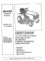
CONGRATULATIONS
on your purchase of a Sears
Tractor_ It has been designed, engineered and manufactured to give you the best possible dependability and
performance.
Should you experience any problem you cannot easily
remedy, please contact }/our nearest Sears Service
Center/Department.
We nave competent, wel!-trained
technicians and the proper tools to service or repair this
unit.
Please read and retain this manual. The instructions will
enable you to assemble and maintain your unit properly.
Atways observe the "SAFETY RULES"..
MODEL
NUMBER
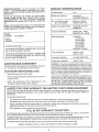
SPECIFICATIONS
HORSEPOWER:
t4 0
GASOLINE CAPACITY:
2 GALLONS
UNLEADED REGULAR
OIL (3.0 PINTS w/o filter)
(3..5 PINTS w/filter)
SAE 30 (or 10W_30)
WINTER: SAE 5W-30
SPARK PLUG (GAP.030 INn): CHAMPION RJ49LM
STD361458
917_255540
VALVE CLEARANCE:
INTAKE _004- °006 IN.
EXHAUST .004 - °006 IN,
GROUND SPEED:
FORWARD
1st 1.01 MPH
2nd 2.07 MPH
3rd 3oll MPH
4th 3.96 MPH
5th 5.07 MPH
6th 5,10 MPH
REVERSE: 1.35 MPH
TIRE PRESSURE:
FRONT: 14 PSi
REAR: 10 PSt
CHARGING SYSTEM:
16 AMPS @3600 RPM
BLADE BOLT TORQUE:
30-35 FT, LBS.
SERIAL
NUMBER
DATE OF PURCHASE
THE MODELAND SERIALNUMBERS
ON A PLATE UNDER THE SEAT.
WILL BE FOUND
YOU SHOULD RECORD BOTH SERIAL NUMBERAN£
DATE OF PURCHASE AND KEEP IN A SAFE PLACE
FOR FUTURE REFERENCE,
MAINTENANCE
AGREEMENT
WARNING: This unit is equipped with an internal combustion engine and should not be used on or near any unimproved forest-covered
brush-covered or grass-covered
tend unless the engine's exhaust system is equipped with
a spark arrester meeting applicable local or state laws (if
any) lfa spark arrester is used, it should be maintained in
effective working order by the operator.
tn the state of California the above is required by !aw
[Section 4442 of the California Public Resources Code)
Other states may have similar laws. Federal laws apply on
federal lands A spark arrester for the muffler is available
through your nearest Sears Authorized Service Center
(See REPAIR PARTS section of this manual)..
A Sears Maintenance Agreement is available on this product. Contact your nearest Sears store for details.
CUSTOMER
RESPONSIBILITIES
,
Read and observe the safety rules.
•
Follow a regular schedule in maintaining, caring for and
using your uniL
•
Follow the instructions
under "Maintenance"
and
"Storage" sections of this owner's manual°
LIMITED TWO YEAR WARRANTY
ON ELECTRIC
START RIDING EQUIPMENT
For two years from date of purchase, when this riding equipment is maintained, lubricated, and tuned up according to the
operating and maintenance instructions in the owner's manual, Sears will repair free of charge any defect in material or
workmanship.
This Warranty does not cover:
,
Tire replacement or repair caused by punctures from outside objects (such as nails, thorns, stumps, or glass)°
Expendable items which become worn during normal use, such as blades, spark plug, air cleaners and belts.
Repairs necessary because of operator abuse or negligence, including bent crankshafts and the failure to maintain the
equipment according to the instructions contained in the owner's manual.
Riding equipment used for commercial or rental purposes°
FULL 90 DAY WARRANTY
ON BATTERY
For 90 days from date of purchase, if any battery included with this riding equipment proves defective in material or workmanship
and our testing determines the battery will not hold a charge, Sears will replace the battery at no charger
WARRANTY SERVICE IS AVAILABLE BY CONTACTING ]'HE NEAREST SEARS SERVICE CENTER/DEPARTMENT IN THE
UNITED STATES, THIS WARRANTY APPLIES ONLY WHILE THIS PRODUCT tS IN USE IN THE UNITED STATES.
This Warranty gives you specific legal rights, and you may also have other rights which vary from state to state.
SEARS, ROEBUCK AND CO., D/731CR-W SEARS TOWER, CHICAGO, IL 60684
3
TABLE
.;AFETY RULES ...........................
JRODUCT SPECIFICATIONS
.................
;USTOMER RESPONSIBILITIES
...............
_"ABLE OF CONTENTS ......................
NDEX ....................................
!VARRANTY ..............................
OF CONTENTS
2
3
3
4
4
5
ASSEMBLY ............................
OPERATION
.........................
MAINTENANCE
........................
SERVICE AND ADJUSTMENTS
............
STORAGE ..............................
TROUBLESHOOTING
...................
REPAIR PARTS ........................
7-9
_.10-13
14-17
18-24
25
26-27
30-50
iNDEX
O
A
Adjustments
Brake .....................
Carburetor ................
Choke .......................
Mower
Front-To-Back
...........
Side-To-Side
.................
Throttle Control Cable ........
Air Filter, Engine ...............
Air Screen, Engine ...............
Assembly ...................
21
24
23
19
18
23
17
16
7-9
B
Battery
Charging ......................
8
Cteaning ...................
16
Installation .................
9
Levels .................
8, 15
Preparation ..................
8
Starting with Weak Battery .....
22
Storage ....................
25
Terminals .................
16
Belt
Motion Drive
Removaf/Replacement .....
21
Mower Blade Drive
Removal/Replacement
.....
20
Blade
Replacement ...............
15
Sharpening .................
t5
Brake Adjustment
..............
21
C
Carburetor, Adjustment ........
Choke, Adjustment
...........
Controls, Tractor
Cutting Level, Mower. .......
24
23
10
11
E
Engine
Adjustments
Carburetor ................
Choke .................
Throttte Control Cable ......
Air Filter ...................
Air Screen ..................
Cooling Fins ...............
Oil Change .................
OIl Level ................
24
23
23
17
16
16
16
t2, 16
Oil Type ....................
Preparation ...............
Starting .....................
Storage ....................
16
12
13
25
F
Filter
Air Cleaner ................
Fuel .....................
Oil ......................
Fuel
Storage ....................
Type .....................
Fuse ......................
17
17
17
25
13
22
H
Headlights ...................
Hood Removal/installation
.......
22
23
L
Leveling Mower Deck ......
Lubrication, Chart ...............
18-19
t4
M
Maintenance .............
14-t7
Air Filter ..................
t7
Foam Pre-Cleaner .........
17
Air Screen Engine ...........
16
Battery .................
15
Blade ....................
15
Cooling Fins, Engine .........
16
Engine Oi! ..................
16
Fuel Filter
17
Lubrication Chart ............
t4
Schedule ................
14
Spark Plugs .................
17
Tire Care .............
8, t5, 22
Transaxle ..................
21
Mower
Adjustment
Front-Tc--Back
............
19
Side-To-Side
............
18
Blade Replacement .........
15
Blade Sharpening .............
15
Cutting Level ...............
11
Installation ................
18
Operation ..................
12
Removal ...................
18
Mowing Tips .................
13
Muffler ........................
17
Spark Arrester . .............
3
4
Oil
Cold Weather Conditions
Engine ....................
Filter ......................
Operating Mower ..............
Operation
...............
...
13, 16
16
17
12
10-13
R
Repair Parts
..............
30-50
P
Parking Brake .............
Parts Bag ...................
Product Specifications ...........
1O,11
6
3
S
Safty Rules ....................
2
Seat ..........................
8
Service and Adjustments ....... t8-24
Carburetor.
.................
24
Choke .......................
23
Fuse ......................
22
Hood Removal/Installation
.....
23
Mower Adjustment
Front-To-Back
...........
t9
Side-To-Side
..............
i8
Motion Drive Belt
Removal/Replacement
....
21
Mower Blade Drive Belt
Removal/Replacement
....
20
Mower Removal .............
t8
Throttle Control Cable .........
23
Tire Care ..............
8, 15, 22
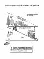
Slope Guide Sheet ...........
5t
Spark Plugs ..................
17
Specifications
..................
3
Starting the Engine ............
13
Steering Wheel ............
7, 21
Stopping the Tractor ...........
11
Storage ....................
25
T
Throttle Control Cable, Adjustment
23
Tires .................. 8, 15, 22
Transaxle, Maintenance ........
21
Trouble Shooting .........
26--27
..... • ............
i,,u,H,
n.
ii
ACCESSORIES
ill
u=,l,
ml
=lu=, ,,,ill..
i u
n.
=u
AND ATTACHMENTS
,
llnl.
unu
=,m,
ii,
................... . = = H,Ju=
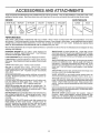
These accessories and attachments were available when the unit was purchased. They are also available at most Sears retait ou'lets,
catalog and service centers Most Sears stores can order these items for you when you provide the model number of your tractor
ENGINE
SPARK PLUG
MAINTENANCE
MUFFLER
ENGINE QIL
I
AIR FILTER
STABfLtZER
BLADES
BELTS
GAS CAN
PERFORMANCE
Sears offers a wide variety of attachments that fit your vehicle_ Many of these are listed below with brief expfanations of how they
can help you This list was current at the time of publication; however, it may change in future years - more attachments may be added,
changes may be made in these attachments, or some may no longer be available or fit your model, Contact your nearest Sears
store for the accessories
and attachments
that are available for your unit.
Most of these attachments
attaching and detaching.
do not require additiona! hitches or conversion
SNOW BLADE for snow removal only, 14-inch high, 42-inch
wide blade clears 38 inch path when angled left or right Raises,
lowers with side leverr Adjustable skids; replaceable, reversible
scraper bar (Use with tire chains, wheel weights, or rear drawbar
weight )
PERMANEX BAGGER lets you collect
grass clippings and
leaves for a healthier, neater looking lawn
Two Permanex
containers hold 30-gallon pfastic bags
LAWN SWEEPERS
let you collect grass cllppings and leaves
LAWN VACS for powerful collections of heavy grass clippings
and leaves. Wand attachment to pick up debris in hard4o-reach
places
CARTS make hauling easy
kits (those that do are indicated) and are designed for easy
SNOWTHR OWER has 40-inch swath Drum-type auger handles
powdery and wet/heavy snow. Mounts easily with simple pin
arrangement
Discharge chute adjusts from tractor seat 6-inch
diameter spout discharges snow 10 to 50 feet Lift controlled at
tractor seat, (Use with chains, wheel weights, or rear drawbar
weight)
Variety of sizes available
ROLLER for smoother lawn surface.
36-inch wide, 18 inch
diameterwater4ightdrumholdsupto3901bs
ofweight Rounded
edges prevent harm to turf Adjustable scraper automatically
cleans drum
TIRE CHAINS are heavy duty; closely spaced extra-large cross
links give smooth ride, outstanding traction_
SPREADER/SEEDERS
make seeding, fertilizing, and weed killing easy. Broadcast spreaders are also useful for granular deicers and sand.
WHEEL WEIGHTS for rear wheels provide needed traction for
snow removal or dozing heavy materials, in pairs (30 Ibs, each )
TRACTOR CAB has heavy duty vinyl fabric over tubular steel
frame, ABS plastic top; clear plastic windshieEd offers 350 degree
visibility Hinged metal doors with catch. Keeps operator warm
and dry Remove vinyl and windshields for use as sun protector
in summer
CORING AERATOR takes small plugs out of soil to aliow moisture and nutrients to reach grass root& 36-inch swath
24
hardened steel coring tips 150 Ib capacity weight tray.
AERATOR promotes deep root growth for a healthy lawn, Tapered 25" steef spikes mounted on 104n diameter discs puncture holes in soil at close intervals to let moisture soak in Steel
weight tray for increased penetration.
Optional accessories for tractor cab: tinted/tempered solid safety
glass windshield with hand operated wiper; 12-volt amber caution
iight for mounting on cab top
DETHATCHER Ioosens soil and flips thatch and matted leaves to
lawn surface for easy pick up. Twenty spring line teeth Useful
to prepare bare areas for seeding. Available for front or rear
mounting
TRACTOR COVER protects tractor from weather
Made of
Evolution 3 fabric (water-repellent, extremely breathable, iight
weight, soft, non-abrasive, pliable in all temperatures, durable,
stain/tear/puncture resistant, wi!l not shrink or stretch)
SPRAYERS use t2-voit DC electric motor that connects to the
tractor battery or other 12wolt source
Includes booms for
automatic spraying when pulling, and hand hetd wand for spot
spraying
Wand has adjustable spray pattern,
For applying
herbicides, insecticides, fungicides, and liquid fertilizers,
5
m
.,.i, iiiiiii,,HI"U.......................
I' "111' IIlI"' I'
'
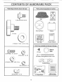
CONTENTS OF HARDWARE
Parts Bag contents
shown full size
Parts packed
PACK
separately
in carton
Q
Seat
Battery acid
(1) Shoulder Bolt 5116-18
Steering Wheel
Battery
(1) Knob
I
Owner's Manual
Parts Bag
(1) Washer 17/32 x 1-3/16 x 12 Gao
Parts bag contents
@
(2) Hex Bolts 1/4 - 20 x 3/4
not shown
full size
Wheel
Steering
Insert
(2) Keys
(2) Hex Nuts 1/4 - 20
(¢
(2) Battery Carriage Bolts 1/4-20 x 7-1/2
(2) Washers 9/32 x 5/8 x 16 Ga
Terminal Guard
(2) Lockwashers
1/4
iii1,111111
iiiii i
ii
m
u
I
J
Z
......
BatieryC.ps '
(2) Wing Nuts 1/4 - 20
15 ° Slope Sheet
iiiii
6
iii
and Instructions
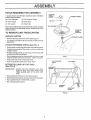
TOOLS
REQUIRED
FOR ASSEMBLY
STEERING
A socket wrench set will make assembly easier. Standard
wrench sizes are listed.
(2) 7/16" wrenches
(1) Tire Pressure Gauge
(1) 9/16" wrench
(1) Screwdriver
(1) 1/2" wrench
(t) Utility Knife
HEX NUT
When right or left hand is mentioned in this manuat, it means
when you are in the operating position (seated behind the
steering wheel)_
TO REMOVE
UNPACK
UNIT FROM CARTON
CARTON
• Remove all loose parts from carton (See page 6).
. Cut, from top to bottom, all four corners of carton and lay
panels flat+
ATTACH
STEERING
WHEEL
(See FIG, 1)
• Remove hex nut and large flat washer from steering shaft.
. Position front wheels of the tractor so they are pointing
straight forward.
• Position steering wheel so cross bars are horizontal (left
to right) and slide onto adapter+
• Secure steering wheel to steering shaft with hex nut and
large flat washer previously removed, Tighten securely
° Snap insert into center of steering wheel
o Remove protective plastic from tractor hood,.
BEFORE ROLLING
(See FIG, 2)
IMPORTANT:
11]
FIG. 1
CLUTCH/BRAKE
LIFT LEVER
PE
UNIT OFF SKID
CHECK FOR AND REMOVE ANY STAPLES iN SKID THAT MAY PUNCTURE
TIRES WHERE UNIT IS TO ROLL OFF
SKID,
- Raise attachment lift lever to its highest position.
- Release parking brake by depressing clutch!brake pedal.
. Place gearshift lever in "NEUTRAL" position°
. Roll unit backwards off skid.
GEARSHIFT
LEVER
FIG. 2
ill
ii
i
ii
illl
ASSEMBLY
illl
illllllllll
illllll
illlll
i
HOW TO SET UP YOUR TRACTOR
PREPARE
...................
BATTERY
INSTALL
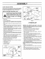
Adjust seat before tightening adjustment knob.
(See FIG. 3)
° Remove cardboard packing on seat pan.
, Place seat on pan and assemble shoulder bolt.
• Assemble adjustment knob and flat washer loosely. Do
not tighten.
° Tighten shoulder bolt securely,
• Lower seat into operating position and sit on seat_
° Slide seat until a comfortable position is reached which allows you to press clutch/brake pedal all the way down.
• Get off seat without moving its adjusted position,
• Raise seat and tighten adjustment knob securely.
i
CAUTION: Wear eye and face shield.
Wash hands or clothing immediately if accidentally in contact with battery acid.
acid
aresmoke.
explosive.
Do not
Fumes from charged battery
Read the instructions
included with the
battery vent caps in the bag of parts. Always wear gloves, clothing and goggles to
protect your hands, skin and eyes,
illlllllllU
i
SEAT (See FIG. 4)
i
Your unit has a battery charging system which is sufficient
for normal use. However, periodic charging of the battery
with an automotive charger will extend its life
* See instructions packed with vent caps in parts bag°
, Fill battery with acid° Fill each cetl until it reaches the bottom of the vent wells. Do not over fill.
SEAT
PAN
, Allow battery to stand and settle for at least thirty minutes.
After standing, check the level of acid. If below the vent
wells, add more acid until the correct level is reached_
SHOULDER
BOLT
While battery is standing (after adding acid) and later, while
battery is being charged, continue with assembly of unit.
, To maximize the life of your battery, it is necessary that
the battery be charged before use. Use a 12 volt battery
charger_ Charge battery at a rate of 6 amperes for 1 houri
Observe all safety precautions required for' battery charging. Failure to charge battery can result in a shortened
battery life.
FLAT
WASHER
ADJUSTMENT
KNOB
o Checkthe acid level after the battery is charged. If the acid
has fallen below the correct level, add distilled or iron free
water.
FIG. 4
o Install the vent caps to cover the vent wells. Wash the top
of the battery with water to remove any acid, then wipe
dry°
CHECK
The tires on your unit were overinflated at the factory for
shipping pu_poses_ Correct tire pressure is important for
best cutting performance.
° Check battery case for Ieakage to make sure that no damage has occurred in handling.
o Dispose of excess battery acid° Neutralize acid for disposal by adding it to four inches of water in a five gallon
plastic container (I 1 cm water in a 19 litre container). Stir
with a wooden or plastic paddle while adding baking soda
until the addition of more soda causes no more foaming°
o Follow instructions on how to install battery.
• Reduce tire pressure to PSI shown in"PRODUCTSPECIFICATIONS" on page 3 of this manual.
CHECK
_
_}"_---_
DECK
LEVELNESS
For best cutting results mower housing should be properly
eveled. See "TO LEVEL MOWER HOUSING" in the Service and Adjustments section of this manual°
CUT AWAY VIEW
I.............
L----.J
TIRE PRESSURE
CHECK
BELTS
VENT CAP
FOR PROPER
POSITION
OF ALL
VENT WELL
See the figures that are shown for replacing motion, mower
drive, and mower blade drive belts in the Service and Adjustments section of this manual. Verify that the belts are routed
cotrectly_
BATTERY
CELL ACID
LEVEL
FIG. 3
8
,11,1
iii 11,.111
,
.................................................
ASS
,i,i,,iii
CHECK
i ,,II,H
BRAKE
, ,,i,,
i
,,
i,
BLY
,
iii
...........................
SYSTEM
ii iiii
WING NUT
TERMINAL
GUARD
After you learn how to operate your tractor, check to see that
the brake is properly adjusted. See"TO ADJUST BRAKE" in
the Service and Adjustments section of this manual.
INSTALL
BATTERY
,
ACCESS
DOOR
(See FIGS. 5 & 6)
AIR DUCT
CAUTION: Do not short battery terminals.
Before installing battery, remove metal
A
bracelets, wristwatch bands, rings, etc.
Positive terminal must be connected first
to prevent
sparking
from accidental
grounding.
=,====,1=
....
,
, HH'
H
• Raise hood
° Lift out air intake duct
BATTERY
BOLT
KEY
HOLE
•
•
•
•
°
Inspection for secure connections (to tighten hardware)
Inspection for corrosion
Testing battery
Jumping (if required)
Periodic charging
#'CHECKLIST
BEFORE YOU OPERATE AND ENJOY YOUR NEW
TRACTOR, WE WISH TO ASSURE THAT YOU RECEIVE
THE BESTPERFORMANCEAND
SATISFACTION FROM
THIS QUALITY PRODUCT
PLEASE REVIEW THE FOLLOWING CHECKLIST:
/ All assembly instructions have been completed.
¢" No remaining loose parts in carton.
/ Battery is properly prepared and charged.
hour at 6 amps)..
v" Seat is adjusted comfortably
FLAT
WASHER
.." %,
NEGATIVI
HEX
BOLT
_BALACK)
BLE
FIG. 5
(Minimum 1
and tightened securely.
7 All tires are properly inflated. (For shipping purposes, the
tires were overinflated at the factory°)
¢" Be sure mower deck is properly leveled side-to-side/
front-to-rear for best cutting results (Tires must be properly inflated for leveling.)
¢" Check mower and drive belts. Be sure they are routed
properly around pulleys and inside all belt keeper&
¢" Check wiring. See that all connections are still secure and
wires are properly clamped,
WHILE LEARNING HOW TO USE YOUR TRACTOR, PAY
EXTRA ATTENTION TO THE FOLLOWING IMPORTANT
ITEMS:
,/Engine
POSITIVE
(RED)
CABLE
BOTTOM OF LIP
FIG. 6
• Make sure drain tube is fastened to drain hole in battery
tray and battery tray is positioned in hole of battery support
, Place battery in plastic tray, battery terminals to front of
tractor
o First connect RED battery cable to positive (+) battery terminal with hex bolt, flat washer, Iockwasher and hex nut
as shown Tighten securely
, Connect BLACK grounding cable to negative (-) battery
terminal with remaining hex bolt, flat washer, Iockwasher
and hex nuL Tighten securely
• Slide the two battery bolts through terminal guard and
start wing nuts onto threads
• Position terminal guard over battery as shown, lower bolts
into key holes and slide square shafts of bolts into slots of
key holes
° Tighten wing nuts by hand making sure battery bolts remain in slots of key holes in battery support.
• Replace air intake duct Make sure bottom lip of air duct
sits between battery and lip of batterie tray
• Be sure terminal access doors are closed
Use terminal access doors for:
BATTERY
BATTERY
TRAY
DRAIN TUBE
oil is at proper level.
€" Fuel tank is filled with fresh, clean, regular unleaded gasolineo
¢ Become familiar with all controls-their
location and function_ Operate them before you start the engine.
¢" Be sure brake system is in safe operating condition.
i
i illl
illlllillllllll
UllUiiiiiUllllllU
i
u
ill
i ilillllllllliiillllllllllll!l
OPERATION
-.
:::: _::]_l_U
] LI _L ILl i ijjl
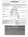
KNOW YOUR TRACTOR
READ THIS OWNER'S
MANUAL
AND SAFETY
RULES
BEFORE
OPERATING
YOUR
TRACTOR.
Compare the illustrations with your Tractor to familiarize yourseff with the locations of various controls and adjustments,
this manual for future reference,
ATTACHMENT
LIGHT
CLUTCH
Save
LEVER
LIFT LEVER PLUNGER
ATTACHMENT
CHOKE
CONTROL
LIFT LEVER
PARKING BRAKE LEVER
CLUTCH/
BRAKE PEDAL
GEARSHIFT LEVER
HEIGHT ADJUSTMENT
KNOB
IGNITION
SWITCH
FIG, 7
A'RrACHMENT CLUTCH LEVER- Used to engage mower'
blades or other attachments mounted to your tractor,
ATTACHMENT LIFT LEVER - Used to raise and lower the
attachment mounted to your tractor,
CLUTCH!BRAKE PEDAL- Used for declutching and braking the tractor,
HEIGHT ADJUSTMENT
height.
KNOB-
LIGHT SWITCH -Turns the headlights on and off,
GEARSHIFT LEVER - Selects the speed and direction of
the tractor,
THROTTLE CONTROLUsed to control engine speed,
IGNITION - Used to start and stop the engine_
PARKING BRAKE LEVER- Locks clutch/brake pedal into
the brake position,,
CHOKE CONTROLUsed when starting a cold engine.
Used to adjust the mower
10
..
i....i..lll.i illl- i
i ........
i ........
i iil.l.il.i
OPEF ATmON
...........
i.i, i.ll=l.=l=.
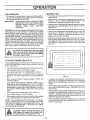
The operation of any tractor can result tn foreign objects thrown into the eyes, which can resu!t
In severe eye damage, Always wear safety glasses or eye shlelos while operating your tractor or
before performing any adjustments or repairs° We recommend wide vision safety mask for over
the spectacles or standard safety glasses.
HOW TO USE YOUR TRACTOR
TO SET PARKING
BRAKE
(See FIG. 8)
• Depress clutch/brake pedal into full"BRAKE"
hold_
position and
o Place parking brake lever in "ENGAGED" position and release pressure from clutch/brake pedal. Pedal should remain in "BRAKE" position. Make sure parking brake will
hold vehicle secure_
STOPPING
"DISENGAGED"
POSITION
ATTACHMENT
CLUTCH
SWITCH
"ENGAGED"
POSITION
IGNITION
GEAR
SHIFT
LEVER
THROTTLE
(See FIG. 8)
MOWER BLADES . Move attachment clutch lever to "DISENGAGED"
tion,
posiCHOKE
GROUND DRIVE. Depress clutch/brake pedal into full "BRAKE" position
. Move gearshift lever to "NEUTRAL" position,
ENGINE "DISENGAGED"
POSITION
. Move throttle control to "SLOW" position.
o Turn ignition key to "OFF" position and remove key, Always remove key when leaving vehicle to prevent unauthorized use.
• Never use choke to stop engine.
TO USE CHOKE
CONTROL
(See FIG. 8)
HEIGHT
ADJUSTMENT
KNOB
Use choke control whenever you are starting a cold engine,
Do not use to start a warm engine.
"BRAKE"
POSITION
• To engage choke control, pull knob out, Slowly push knob
in to disengage.
TO USE THROTTLE
CONTROL
CLUTCH/BRAKE
PEDAL "DRIVE"
POSITION
(See FIG. 8)
FIG. 8
Always operate engine at full throttle.
TO ADJUST
• Operating engine at less than full throttle reduces the battery charging rate and the engine cooling air flow.
•Fuli throttle offers the best mower performance.
FIG. 8)
The cutting height is controlled by turning the height adjust_
merit knob in desired direction.
TO MOVE
FIG. 8)
• Turn knob clockwise to raise cutting height
• Turn knob counterclockwise to fower cutting height,
FORWARD
AND BACKWARD
(See
The direction and speed of movement is controlled by the
gearshift lever.
CUTTING
HEIGHT
(See
The cutting height range is approximately 1-1/4" to 3-3/4",
The heights are measured from the ground to the blade tip
with the engine not running, These heights are approximate
and may vary depending upon soil conditions, height of
grass and types of grass being mowed,
, Start unit with clutch!brake pedal depressed and the
gearshift lever in "NEUTRAL" position.
° Move gearshift lever to desired position,
• Slowly release clutch/brake pedal to start movement
IMPORTANT:
MOWER
• The average Iawn should be cut approximately 2-1/2"
during the cool season and over 3" during hot months. For
healthier and better looking lawns, mow often and after
moderate growth.
• For best cutting performance, grass over 6" in height
should be mowed twice Make the first cut relatively high;
the second to desired height°
BRING TRACTOR
TO A COMPLETE
STOP BEFORE SHIFTING OR CHANG*
ING GEARS_
11
OPERATIO
TO OPERATE
TO OPERATE
(See FIG. 8 & 9)
MOWER
,,,,,,,,,,,,,,,,,,,,,,,
Your unit is equipped with an operator presence sensing
switch. Any attempt by the operator to leave the seat with
the engine running and the attachment clutch engaged will
shut off the engine.
• Choose the slowest speed before starting up or down
hills.
• Avoid stopping or changing speeds on hills.
• If slowing is necessary, move throttle control lever to
slower position.
• If stopping is absolutely necessary, push clutch/brake
pedal quickly to brake position and engage parking brake,
o Move gearshift lever to "NEUTRAL" position.
= To restart movement, release parking brake and move
gearshift lever to 1st gear. Be sure youhave allowed room
for' unit to roll slightly as you restart movement,
° Slowly release parking brake and clutch/brake pedal.
° Make all turns slowly.
° Engage mower by slowly moving attachment clutch lever
to "ENGAGED" position.
• TO STOP MOWER - Move attachment clutch Iever to
"DISENGAGED" position_
° Raise attachment lift lever_
i1,1,,,,,, i,,
CAUTION: Do not operate the mower wlth-_
out either the entire grass catcher, on mow-_
ors so equipped, or the discharge guard lnl
p!a
ce-
,
with slopes greater than 15 ° and do not|
CAUTION: Do not drive up or down htllsJ
drive across any slope.
J
• Select desired height of cut, using height adjustment
knob
• Lower attachment lift lever.
_k
ON HILLS
,.........
TO TRANSPORT
. Raise attachment lift control to highest position.
o When pushing o! towing your unit, be sure gearshift lever
is in NEUTRAL' position.
= Do not push or tow unit at more than 5 MPH.
BEFORE
CHECK
R,H_RUNNER
STARTING
ENGINE
THE ENGINE
OIL LEVEL
(See FIG. 10)
, The engine in your unit has been shipped, from the fac_
tory, already filled with summer weight oi!.
° Check engine oil with unit on level ground.
• Remove oil fill dipstick and wipe clean replace and screw
cap t ght, wait for a few seconds, remove and read oil
level if necessary, add oil until "FULL" mark on dipstick is
reached. Do not overfill
DISCHARGE
GUARD
, Forcold weather oper'ationyou should change oi! for easier starting (See "OI L VISCOSITY CHART" in the Maintenance section of this manual).
• To change engine oil, see the Maintenance section in this
manual.
FIG. 9
OIL FILLER CAP
AND DIPSTICK
AIR INTAKE DUCT_
FIG. 10
12
,, ii ,, ,11,
,,,i
i
i,
iii
OPERATmO
i,
,ii
...................
i,iiiii
,,,MI,
III,H
MOWING
ADD GASOLINE
• Fill fuel tank, Use fresh, clean, regular unleaded gasoline
(Use of leaded gasoline will increase carbon and lead oxide deposits and reduce valve life)
IMPORTANT:
TIPS
o Tire chains cannot be used when the mower housing is attached to unit
• Mower should be properly leveled for best mowing performance. See "TO LEVEL MOWER HOUSING" in the
Service and Adjustments section of this manual
• Use the runner on the right hand side of mower as a guide.
The blade cuts approximately an inch outside the runner
(See FIG. 9).
• The left hand side of mower should be used for trimming
WHEN OPERATINGINTEMPERATURES
BELOW 32°F (0°C), USE FRESH CLEAN
WINTER GRADE GASOLINE TO HELP
INSURE
GOOD
COLD
WEATHER
START! NG.
WARNING'. Experience indicates that alcohol blended fuels
(called gasohol or using ethanol or methanol) can attract
moisture which leads to separation and formation of acids
during storage. Acidic gas can damage the fuel system of an
engine while in storage. To avoid engine problems, the fuel
system should be emptied before storage of 30 days or
longer. Drain the gas tank, start the engine and let it run until
the fuel lines and carburetor are empty Use fresh fuel next
season, See Storage section of this manual for additional
information, Never use engine or carburetor cleaner products in the fuel tank or permanent damage may occur
= Drive so that clippings are discharged onto the area that
has been cut Have the cut area to the right of the machine. This will result in a more even distribution of clippings and more uniform cutting.
= When mowing large areas, start by turning to the right so
that clippings will discharge away from shrubs, fences,
driveways, etc After one ortwo rounds, mow in the opposite direction making left hand turns until finished (See
FIG 11).
I
CAUTION: Fill to bottom of gas tank ftllerl
neck° Do not overfill Wipe off any spilled R
oil or fuel. Do not store, spill or use gaso-_
line near an 0pen flame,
TO START
ENGINE
, .....
!
(See FIG. 8)
When starting engine for the first time or if engine has run out
of fuel, it wilt take extra cranking time to move fuel from the
tank to the engine.
•
•
.
Depress the clutch/brake pedal and setthe parking brake
Place gearshift lever in "NEUTRAL" position
Move attachment clutch to"DISENGAGED"
position
Pull choke control out to "CHOKE" position for cold engine start. For warm engine start do not use choke control.
FIG. 11
• Move throttle control to midway between "FAST" and
"SLOW" positions.
. Turn ignition key clockwise to "START" position and release key as soon as engine starts. Do not run starter
continuously for more than fifteen seconds per minute. If
engine does not start after several attempts, move throttle control to "FAST" position, wait a few minutes and try
again
. When engine starts, slowly push choke control in
o Move throttle control to "FAST" position.
• Allow engine to warm up for a few minutes before engaging clutch/brake pedal or attachment clutch switch.
° If grass is extremely tall, it should be mowed twice to re_
duce load and possible fire hazard from dried clippings,
Make first cut relatively high, the second to the desired
height.
• Do not mow grass when it is wet. Wet grass will plug mower and leave undesirable clumps. AlIow grass to dry before mowing
• Always operate engine at full throttle when mowing to assure better mowing performance and proper discharge of
material
Regulate ground speed by selecting a tow
enough speed to give the mower cutting performance as
well as the quality of cut desired.
o When operating attachments, select a ground speed that
will suit the terrain and give best performance of the attachment being used
NOTE: If at a high altitude (above 3000 feet) or in cold temperatures (below 32°F or 0°C), the carburetor fuel mixture
may need to be adjusted for best engine performance. See
"TO ADJUST CARBURETOR" in the Service and Adjustments section of this manual.
i ii1,111
,i,
I_)
stall mower or remove front mower sus- I
AUTION:bracket
Before
the tractor,
pension
anddriving
suspension
arms, In- Ii
.........................
: ................................
,.....
13
NTE
MAINTENANCE
CE
r
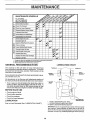
SCHEDULE
FILLIN DATES
AS YOUCOMPLETE
......
REGULAR
SERVICE ....
L
___-_J_
€/Y'/_'4.-_/"S
ERVICE DATES
Check Brake Operation
T
CheckTire Pressure
A
C
Checkfor LooseFasteners
Sharpen/ReplaceMowerBlades
LubricatePivotPoints
T
CheckBatteryLevel/Recharge
C!ear_Batteryand Terminals
J
Check EngineOil Level
ChangeEngineOil
CleanAir Filter/FoamPro+cleaner
N
E Or+an
At;Screen
G
Inspect
Muffler/Spark
1
Change
Engine Oil Fitter
N
Clean Engine
E
Reptace Spark Plug
Replace
I_+,=
+
v',
Arrestor .....
v'
Cooling Fins
Air Filter Paper Cartridge
ReplaceFuelFilter
1 ,, Change more often when operating under a heavy load ot in h{gh ambient temperatures
2 +Service more often when operellng In dirty or dusty conditions
3 +Replace blades more often when mewing In sandy sot{
GENERAL
RECOMMENDATIONS
LUBRICATION,CHART
The warranty oft this unit does not cover items that have
been subjected to operator' abuse or negligence° To receive
full value from the warranty, operator must maintain unit as
instructed in this manual.
**SPINDLE
__
BEARING
Some adjustments will need to be made periodically to properly maintain your unit.
WHEEL
BEARING **
All adjustments in the Service and Adjustments section of
this manual should be checked at least once each season=
• Once a year you should replace the spark plug, clean or
replace air _ter, and check blades and belts for wear. A
new spark plug and clean air filter assure proper air-fuel
mixture and help your engine run better and last longer.
BEFORE
•
•
•
•
Check
Check
Check
Check
EACH
PIVOT
USE
engine oil level
brake operation+
tire pressure.
for loose fasteners.
* BOTH ENDS OF
SHIFTER SHAFT
LUBRICATION
Keep unit well lubricated (See "LUBRICATION
CHART")
*
**
SAE 30 or 10W30 MOTOR OIL API - SF!CC
EXTREME PRESSURE LUBRICATING
GREASE
*_
REFER TO ENGINE MAINTENANCE
SECTION
IMPORTANT: Do not oilor grease the pivotpointswhichhave special
nylon beatings, Viscous lubricantswileattract dust and dirt that wi{i
shortenthe life of the self-lubricatingbearings,If youfeel they must be
lubricated, use on+ya dry, powderedgraphite type lubricant sparingly,
14
i, nlUUUl
nl ,Ul,,nlnnlll
MAINTENANCE
.................
i
i
n,,,,,,,i,u,nl,
TRACTOR
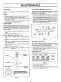
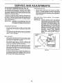
TO SHARPEN BLADE (See FIG. 13)
Always observe safety rules when performing any maintenance
Care should be taken to keep the blade balanced, An unbalanced blade will cause excessive vibration and eventual
damage to mower and engine,
TIRES
• The blade can be sharpened with a file or on a grinding
wheel, Do not attempt to sharpen while on the mower
• To check blade balance, drive a nail into a beam or wall
Leave about one inch of the straight nait exposed, Place
center hole of blade over the head of the nail, tf blade is
balanced, it should remain in a horizontal position
If
either end of the blade moves downward, sharpen the
heavy end until the blade is balanced,
• Maintain proper air pressure in all tires (See "PRODUCT
SPECIFICATIONS" on page 3 of this manual),
• Keep tires free of gasoline, oil, or insect control chemicals
which can harm rubber,
• Avoid stumps, stones, deep ruts, sharp objects and other
hazards that may cause tire damage
BLADE
CARE
For best results mower blades must be kept sharF The
blades can be sharpened with a file or on a grinding wheel.
We suggest they be sharpened or replaced after every 25
hours of mowing, Check blades more often if mowing _n
sandy conditions,
II
}
O j¸
• Do not attempt to sharpen blades while they are on the
mower,
° Replace bent or damaged blades,
BLADE
REMOVAL
o_
BLAD_
(See FIG. 12)
. Raise mower to highest position to allow access to
blades,
. Remove hex bolt, lockwasher and flat washer securing
blade
FIG. 13
. Install new or resharpened blade with trailing edge up towards deck as shown,
BATTERY
° Reassemble hex bolt, Iockwasher and fiat washer in exact
order as shown,
Your unit has a battery charging system which is sufficient
for normal use_ However, periodic charging of the battery
with an automotive charger will extend its life
• Tighten bolt securely (30-35 Ft, Lbs,)
IMPORTANT:
BLADE BOLT
TREATED,
IS
GRADE
5
(See FIG. 14)
, Acid solution level in each battery cell should be even with
bottoms of vent wells Add only distilled or iron-free water
if necessary, Do not overfill,
HEAT
CUT AWAY VIEW
F
MANDREL
ASSEMBLY
]'_'_
_------r_
_
r'x"'''"'_
VENT
CAP
_ BATTERY
BLADE
I H
R ,[/J
_
R P'_
"_
R I -.-,-" BATTERY
CELL
FIG. 14
WASHER__
•
•
•
•
HEX BOLT
(GRADE5)
LOCKWASHER
Q
_
A GRADE 5 HEAT TREATED BOLT
CAN BE IDENTIFIED BYTHREE LINES
ON THE BOLT HEAD AS SHOWN AT
LEFT
FIG. 12
1R
Keep battery and terminals clean
Keep battery bolts tight,
Keep vent caps tight and small vent holes in caps open.
Recharge at 6 amperes for 1 hour,
HH'HHIH'I'H
'"'11'
I
IVIAINT
CE
TO CLEAN BATTERY AND TERMINALS -
° After oil has drained completely, replace oil drain plug arid
tighten securely.
• Refill engine with oil through oil fill dipstick tube. Pour
slowly. Do riot overfill. For approximate capacity see
"PRODUCT SPECIFICATIONS" on page 3 of this manuaL
Corrosion and dirt on the battery and terminals can cause
the battery to "leak" power.
* Remove terminal guard.
* Disconnect BLACK battery cable first then RED battery
cable and remove battery from tractor.
° Wash battery with solution of four tablespoons of baking
soda to one galfon of water. Be careful not to get the soda
solution into the ceils.
- Use gauge on oil fitt dipstick for checking level. Be sure
dipstick cap is tightened securely for accurate reading
Keep oil at "FULL" line on dipstick.
RECOMMENDED
, Rinse the battery with plain water and dry
° Clean terminals and battery cable ends with wire brush
until bright
° Coat terminals with grease or petroleum jelly.
, Reinstall battery (See "INSTALL BATTERY" in the Assembly section of this manual).
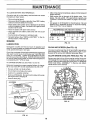
°F -20°
°C -29 °
0°
-18 °
SAE VISCOSITY
32 °
0°
60°
16°
GRADES
80 °
27 °
100 °
38 °
ENGINE
FIG= 16
LUBRICATION
Change the oil after the first two hours of operation arid
every 50 hour s thereafter or at least once a year if the tractor
is not used for 50 hours in one year.
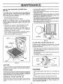
CLEAN
AIR SCREEN
(See FIG. 15)
Air screen must be kept free of dirt and chaff to prevent engine damage from overheating, Clean with a brush or compressed air to remove dirt, stubborn dried gum fibers,
Check the crankcase oil leve_ before starting the engine and
after each five (5) hours of continuous use. Add SAE 30W
motor oil or equivalent Tighten oil fill cap/dipstick securely
each time you check the oil level, SAE 5W-30 motor oil may
be used to make starting easier in areas where temperature
is consistently 32 ° F (0°C) or lower.
CLEAN
ENGINE
COOLING
FINS (See FIG, 17)
Remove any dust, dirt or oil from engine cooling fins to prevent damage from overheating. Air guide covers must be removed, Remove side panels and hood (See "TO REMOVE
HOOD AND GRILL ASSEMBLY" in Service and Adjust=
ments section of this manuat
TO CHANGE ENGINE OIL (See FIGS. 15 and 16)
Determine temperature range expected before oil change.
All oil must meet API service classification SD, SE or SF.
• Be sure vehicle is on level surface.
, Oil will drain more freely when warm.
, Catch oil in a suitable container.
• Remove oil fill dipstick. Be careful riot to allow dirt to enter
the engine when changing oil.
, Remove drain plug.
AIR SCREEN
CLEAN THESE
AREAS OF DIRT
AND DEBRIS
ENGINE OIL DIPST|CF
FIG. 17
OIL DRAIN PLUG
FIG. 15
16
AIR FILTER
FOAM PRE-CLEANER
o Unscrew old filter byturning counterclockwise
able container to catch oil.
(See
FIG, 18)
Your
using
after
used
Use a suit-
* Apply a thin coating of new engine oil to rubber gasket on
replacement oil filter.
o Install replacement oil filter on filter adapter. Turn oil filter
clockwise until rubber gasket contacts filter adapter, then
tighten filter an additional 1/2 to 3/4 turn
, Fill crankcase with new oil ( See "TO CHANGE ENGINE
OIL"). For approximate capacity see "PRODUCT SPECIFICATIONS" on page 3 of this manual
* Start engine and check for oil leaks. Correct any leaks before placing engine into full operation
engine will not run properly and may be damaged by
a dirty air filter_ Clean the foam pre-cleaner element
every 25 hours of operation, more often if tractor is
in very dusty, dirty conditions.
• Unscrew knob and open cover.
• Remove cartridge and foam pre-cleaner.
NOTE: Do not attempt to clean or oil the paper cartridge.
Replace paper cartridge once a year or after every 100
hours of operation, more often if used in very dusty or dirty
conditions,
• Wash foam pre-cleaner in liquid detergent and water,
• Wrap foam pre-cleaner in cloth and squeeze dry,
• Lightly coat foam pre-cleaner with clean engine oil,
Squeeze in towel to remove excess oil_ Do not saturate,
• Install foam pre-cleaner in cover,
• tnstal_ cartridge in cover with tabs on cartridge in slots on
cover, Use new cartridge if old one is dirty or wet
• Close cover and tighten knob securely,
_,=
'_
OIL FILTER
FIG. 19
IN-LINE
(See FIG. 20)
Fuel filter should be replaced once each season. If fuel filter
becomes clogged, obstructing fuel flow to carburetor, replacement is required
CAR_DGE
FOAM
'X
PRE-CLEANER
FUEL FILTER
\
o With engine coot, remove filter and plug fuel line sections
* Place new fuel filter in position in fuel line with arrow pointing towards carburetor
, Be sure there are no fueI line leaks and clamps are properly positioned.
, immediately wipe up any spilled gasoline
i
TABS
COVER
KNOB
FIG. 18
MUFFLER
Inspect and replace corroded muffler and spark arrester (if
equipped) as it could create a fire hazard and/or damage.
SPARK
FIG. 20
CLEANING
PLUGS
* Clean engine, battery, seat, finish, etc. of all foreign matter.
Replace spark plugs at the beginning of each mowing season or after every 100 hours of use, whichever comes first.
Spark plug type and gap setting is shown in "PRODUCT
SPECIFICATIONS" on page 3 of this manual.
ENGINE
OIL FILTER
o Keep finished surfaces and wheels free of all gasoline, oil,
etc.
, Protect painted surfaces with automotive type wax.
(See FIG. 19)
We do not recommend using a garden hose to clean your
unit unless the electrical system, muffler, air filter and carburetor are covered to keep water out Water in engine can result in a shortened engine fife.
Replace the engine oil fi_ter every season or every other oil
change if the tractor is used more than 100 hours in one
year.
17
•
Depress clutch/brake
•
•
•
•
Place gearshift lever in "NEUTRAL" position.
Place attachment clutch in "DISENGAGED" position.
Turn ignition key "OFF" and remove key.
Make sure the blades and all moving parts have completely stopped.
•
pedal fully and set parking brake=
Disconnect spark plug wire from spark plug and place wire where it cannot come in contact with
plug.
H,
=
=,
I,l=,N,H I, H H I ll= HIH,H,=H,==
=
TRACTOR
TO REMOVE
TO INSTALL
MOWER
(See Fig. 21)
Mower will be easier to remove from the right side of unit.
•
Remove mower blade drive belt from engine pulley
only (See "TO REPLACE MOWER BLADE DRIVE
BELT" through step removing belt from electric clutch
pulley)_
MOWER
(See Fig. 21)
•
Raise attachment lift lever to its highest position.
•
Turn height adjustment knob to lowest setting.
•
Slide mower under tractor with discharge guard to right
side of tractor.
•
Install parallel link to front axle and mower with hinge
pins Secure hinge pins with retainer springs
°
Lower attachment lift lever to lower suspension arms
Slide trunnions through lift bracket holes and secure
with retainer springs.
•
.
Remove retainer spring from clutch rod; pult clutch rod
out of clutch iever
,
Pull retainer springs out of rear suspension trunnions
Remove rear suspension trunnions from lift brackets.
.
Putl retaine_ springs from front hinge pins
•
Roll belt over electric clutch pulley Make sure belt is
inside all pulley grooves and inside belt guides
Raise attachment lift lever to raise mower
•
Remove hinge pins attaching parallel link to mower
and front axle.
•
Turn height adjustment knob to desired setting.
•
Raise lift lever to raise suspension arms
out from under tractor_
TO LEVEL MOWER
IMPORTANT:
Slide mower
IFAN ATTACHMENT OTHERTHAN THE
MOWER tS TO BE MOUNTED TOTHE
TRACTOR, THE R,H. AND L.H. SUS_
PENSION ARMS MUST BE REMOVED
FROM TRACTOR
CLUTCH
LEVER_
RETAINER
SPRINGS
Adjust the mower while tractor is parked on level ground or
driveway.
Make sure tires are properly inflated (See
"PRODUCT SPECIFICATIONS"
on page 3). If tires are
over or under inflated, you will not properly adjust your
mower.
SIDE-TO-SIDE ADJUSTMENT (See Figs. 22 and 23) •
Raise attachment lift lever to its highest position.
I
CLUTCH
ROD
CLUTCH
TRUNNIOI
LIFT
BRACKET
PINS
RETAINER
SPRING
HOUSING
ENGINE
PULLEY
FIG. 21
18
•
Measure height from bottom of deck curl to ground
level at front corners of mower° Distance "A" should be
the sarne.
•
If distance "A" needs to be changed, snap out access
hole cover on left side of tractor above footrest
•
To raise left side of mower, loosen nut "B" and tighten
nut "C"_
•
To lower left side of mower, loosen nut "C" and tighten
nut "B".
,
When distance "A" is equal, securely tighten nuts "B"
and "C"_
•
Replace access hole cover.
SERVDCE AN
i,%,1 ,IIH,
i i1,1,,
ADJUSTMENTS
ii ,i H,,IINIIH
FRONT-TO-BACKADJUSTMENT
(See Figs 24 and 25) To obtain the best cutting results, the mower housing
should be adjusted so the front is approximately 1/2 to 3/4"
(1.3 cm to 1,9 cm) lower than the rear when the mower is
in its highest position.
Check adjustment on right side of tractor° Measure distance "D" at front and rear flanges of mower housing as
shown.
BOTTOM
OF CURL
BOTTOM
OF CURL
•
To raise rear of mower, loosen nut "E" on both rear
suspension arms,, Screw both nuts "F" on both rear
suspension arms an equal number of turns,
•
When distance "D" is 3/4" to 7/8" higher at rear than
front, retighten nuts "E".
•
Recheck side-to_side adjustment,
IMPORTANT:
GROUNDLINE
FIG. 22
WHEN ADJUSTING
REAR SUSPENSION TRUNNIONS, ALWAYS ADJUST
BOTH EQUALLY SO MOWER WILL
STAY LEVEL SIDE-TO-SIDE
REAR SUSPENSION
ARM
)
NUT"B"
BOTTOM
OF CURL
_1
E TOSIDE
_
"_ ADJUSTMENT
TRUNNION
DTREAR SUSPENSION
FIG. 23
GROUND _" D
TRUNNION
LINE
FIG, 24
REAR
SUSPENSION
TRUNNION
REAR
SUSPENSION
ARM
NUT "F"
LIFTBRACKET
FIG. 25
19
i i
i i
.......................................................................
SERVICE AN
TO ADJUST
MOWER
(See Fig. 26)
BLADE
DRIVE
ADJUSTMENTS
BELT
IDLER BELT
GUIDE
Your tractor' has been manufactured with the ability to
readjust the mower blade drive belt to provide you with
longer belt life.
Remove the bolt, nut and D-shaped washers from
rock shaft assembly.
•
Move extension spring from lower to upper end of
slot in rock shaft assembly and install bolt, nut and
the D-shaped washers (flat side of washers down)°
,
Tighten bolt and nut to secure the D-shaped washers (flat side down as shown)
ENGINE PULLEY
L,H°
MANDREL
With engine off and the lift lever in the highest position,
move attachment clutch lever slowly forward. If the lever
moves significantly forward in the slot before resistance
is felt, adj"ustment is necessary.
•
Lower the mower deck for easier access.
•
BELT
IDLER
EXTENSION
R,Ho
MANDREL
ROCKSHAFT
NOTE: When installing a new belt, be sure spring is in
lower end of slot,
TO REPLACE
MOWER
(See Figs. 26 and 27)
BLADE
DRIVE
BELT
The mower blade drive belt may be replaced without
tools Park the tractor on level surface, Engage parking
brake, For assistance, there is a bett installation guide
decat on the mower housing°
BELT REMOVAL
SPRING
BRAKE
ROD
-
•
•
Ptace attachment clutch in "DISENGAGED" position.
Move attachment lift lever forward to lower mower to
its lowest position_
•
Roll belt off engine pulley_
•
Pull belt off both mandrel puIleys,
•
Spring belt guide away from idler putley and pull belt
off idter pulley,
•
Slide belt from under extension spring,
NUT
BELT INSTALLATION
FIG. 26
-
•
Slide belt under extension spring=
•
Place belt around back side and in groove of both
mandrel pulleys,
•
Spring idler belt guide down and place belt around
rear side of idler pulley
°
Roll belt over engine pulley,
°
Make sure belt is in all pulley grooves and inside all
belt guides.
BELT
GUIDES
L
FIG. 27
2O
ENGINE
PULLEY
SERVICE AND ADJUSTMENTS
.......
11 =l, nmuinllll
TO ADJUST
BRAKE
(SEE FIG. 28)
TRANSAXLE
JUSTMENT
Your unit is equipped with an adjustable brake system
which is mounted on the right side of the transaxle.
Depress clutch/brake pedal and engage parking brake.
Measure distance between brake operating arm and
nut "A" on brake rod.
•
If distance is other than 1-t/2", disengage parking
brake, loosen jam nut and turn nut "A" until distance
becomes 1-1/2". Retighten jam nut against nut "A"o
o
Engage parking brake and recheck distance°
•
Road test unit for proper stopping distance as stated
above. Readjust if necessary. If stepping distance is
still greater than 6 feet (1 8 metres) in highest gear,
further maintenance is necessary. Contact your nearest
Authorized Service Center.
WITH PARKING
AND
AD-
The transaxle should be in neutral when the gearshift lever
is in the neutral (lock gate) position. The adjustment is
preset at the factory; however, if adjustment is needed,
proceed as follows_
.
Make sure transaxte is in neutral, Loosen two Iocknuts
on tie rod.
if unit requires more than 6 feet stopping distance at high
speed in highest gear, then brake must be adjusted.
•
.
SHIFTER
LINKAGE
(See FIGS. 30 and 31)
•
Turn center rod until gearshift lever falls into neutral
lock gate on fender consoled
•
Turn center rod until gearshift lever fails into neutra!
lock gate on fender console,
•
Tighten locknuts securely.
;HIFT LEVER
;K GATE
BRAKE "ENGAGED"
JAM NUT
OPERATING
FIG_ 28
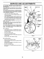
TO REPLACE
MOTION
FIG, 30
DRIVE BELT (See FIG.
LOCKNLr[S
29)
Park the tractor on Ievel surface Engage parking brake,
For ease of service there is a belt installation guide decal on
bottom side of left footrest.
•
Remove mower (See "TO REMOVE MOWER" in this
section of this manual)
•
Remove belt from stationary idler and clutching idler.
•
Remove belt from engine pultey_
ROD
TIE
•
Roll belt over top of transmission pulley.
•
Install new beft by reversing above procedure.
IMPORTANT:
REPLACE ONLY WITH BELT LISTED IN
THIS MANUAL.
TRANSAXLE
FIG. 31
TO ADJUST
STEERING
WHEEL
ALIGNMENT
If steering wheel crossbars are not horizontal (left to right)
when wheels are positioned straight forward, remove
steering wheel and reassemble per instructions in the
Assembly section of this manual.
FRONT WHEEL
ENGINE
PULLEY
The front wheel toe-in and camber are not adjustable on
your unit, If damage has occured to affect the front wheel
toe-in or camber, contact your nearest Authorized Service
Center
IDLER
TRANSAXLE
PULLEY
CLUTCHINC
IDLER
FIG_ 29
TOE-IN/CAMBER
21
J,J
SERVICE AN
ADJUSTMENTS
::::::::::::::::::::::::i=, i
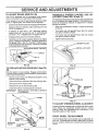
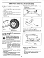
TO REMOVE
Fig. 32)
WHEEL
FOR REPAIRS
H,i
TO REMOVE CABLES, REVERSE ORDER -
(See
•
Block up axle securely.
*
Remove hub cap, retaining ring and washers to allow
wheel removal (rear wheel contains a square key - Do
not Iose)_
°
Repair tire and reassemble°
•
On rear wheels only: align grooves in rear wheel hub
and axle. Insert square key_
•
BLACK cable first from left side of chassis and fully
charged battery.
o
RED cable last from both batteries.
Replace washers and snap retaining ring securely in
axle groove°
.
ii =l,,= ,=lNi ,Hi ll=lN= H= l liH
"POSITIVE"
"NEGATIVE"
(+)
Replace hub cap.
(-)
FIG. 33
WASHERS
RETAINING
RING
"_
FIG. 34
!
TO REPLACE
HUB CAP
SQUARE
PANEL
BOLT
KEY
FUSE (See Fig. 35)
Replace with 30 amp automotive*type ptug-in fuse° The
fuse holder' is located under' the dash, directly behind the
engine,
(REAR WHEEL ONLY)
FIG. 32
TO START ENGINE WITH A WEAK
(See Figs, 33 & 34)
BATTERY
CAUTION: Lead-acid batteries generate explosive gases. Keep s parks, flame
and smoking materials away from batteries.
Always wear eye protection
when around batteries.
If your battery is too weak to start the engine, it should be
recharged,
If "jumper cables" are used for emergency
starting, follow this procedure:
IMPORTANT:
FUSE
HOLDER
YOUR UNIT tS EQUIPPED WITH A 12
VOLT NEGATIVE GROUNDED SYSTEM.
THE OTHER VEHICLE MUST ALSO BE
A 12 VOLT NEGATIVE GROUNDED
SYSTEM. DO NOT USE YOUR TRAC*
TOR BATTERY TO START OTHER VEHICLES,
FIG 35
TO REPLACE
HEADLIGHT
BULB
TO ATTACH JUMPER CABLES -
•
Raise hood.
•
Connect each end of the RED cable to the POSITIVE
(+) terminal of each battery, taking care not to short
against chassis.
•
Pull bu[b holder out of the hole in the backside of the
gritl.
•
•
Connect one end of the BLACK cable to the NEGATIVE (-) terminal of fully charged battery.
Replace bulb in holder and push bulb holder securely
back into the hole in the backside Of the grill
CIose hood.
•
Connect the other end of the BLACK cable to a panel
bolt on the left side of the chassis, away from fuel tank
and battery,
•
22
...................
ii
ii
iii iiii ii
SERVICE AN
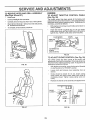
TO REMOVE HOOD AND GRILL
(See Figs. 36 and 37)
ADJUSTMENTS
ENGINE
ASSEMBLY
•
Raise hood.
•
Unsnap headlight wire connector.
•
Carefully remove wing nuts from rear of side panels°
•
Stand at front of tractor. Grasp hood and side panels,
tilt forward and lift off unit.
TO ADJUST
THROTTLE
(See Fig. 38)
CONTROL
CABLE
The throttle control has been preset at the factory and
adjustment shoutd not be necessary. Check adjustment as
described below before loosening cable. If adjustment is
necessary, proceed as follows:
•
With engine not running, move throttle control lever to
"FAST" position_
•
Check that swivel is against stop. If it is not, loosen
cable clamp screw and pull cable back until swivel is
against stop. Tighten cable clamp screw securely
To reinstall, reverse above procedure.
CLAMP SCREW
SWIVEL
/
THROTTLE
/
__/__
"_-1\\
_
CABLE
GOVERNED
SPRING
K, l/
_k\\
, ..".,_.
IDLE
_
_._-,.,,r_
'_'_"-
(RED OR WHITE)
FIG. 38
TO ADJUST
CHOKE
CONTROL
(See Fig. 39)
The choke control has been preset at the factory and
adjustment should not be necessary. Check ad ustment as
described below before loosening cable_ If adjustment s
necessary, proceed as follows:
FIG, 36
o
With engine not running, move choke control (located
on dash panel) to full "CHOKE" position
•
Loosen knob and remove cover assembly from air
cleaner.
•
Choke should be closed. If it is not, loosen casing
clamp screw and move choke cable until choke is
completely closed. Tighten casing damp screw securely.
•
Replace air cieaner cover assembly and tighten knob.
LE /JCHOKEI
FIG. 39
F1G. 37
23
,,,,,,
i,i
i i i,iii
SERVICE AN
II
iiiiiiiiiii iii i iii i ii ii
ii
ADJUSTMENTS
...............
HHH,H=, H=
TO ADJUST
CARBURETOR
(See Fig. 40)
The carburetor has been preset at the factory and adjustment should not be necessary. However, minor adjustrnent may be required to compensate for differences in fuel,
temperature, altitude or load. If the carburetor does need
adjustment, proceed as follows:
ACCELERATION
"
In general, turning the mixture screw In (clockwise) decreases the supply of fuel to the engine giving a leaner fuel/
air mixture. Turning the mixture screw out (counterclockwise) increases the supply of fuel to the engine giving a
richer fuel!air mixture.
IMPORTANT:
DAMAGE TO THE NEEDLES AND THE
SEATS IN CARBURETOR MAY RESULT
IF SCREW IS TURNED IN TOO TIGHTo
PRELIMINARY
SETTING -
•
Be sure you have a clean air filter, and the throttle
control cable and choke are adjusted properly (see
above).
•
With enpine off turn idle mixture screw In (clockw se)
dosing it finger tight and then turn out (counterclockwise) !-1/4 to 1-1/2 turns_
TEST-
Move throttle control lever from "SLOW" to "FAST"
position. If engine hesitates or dies, turn idle mixture
screw out (counterclockwise)
1/8 turn. Repeat test
and continue to adjust, if necessary, until engine accelerates smoothly.
High speed stop is factory adjusted.
Do not adjust o.
damage may result.
IMPORTANT:
NEVER TAMPER WITH THE ENGINE
GOVERNOR, WHICH IS FACTORY SET
FOR PROPER ENGINE SPEED. OVERSPEEDING THE ENGINE ABOVE THE
FACTORY HIGH SPEED SETTING CAN
BE DANGEROUS° IF YOU THINK THE
ENGINE_GOVERNED
HIGH SPEED
NEEDS ADJUSTING, CONTACT YOUR
NEAREST
AUTHORIZED
SERVICE
CENTER,
WHICH
HAS PROPER
EQUIPMENT AND EXPERIENCE TO
MAKE ANY NECESSARY
ADJUSTMENTS.
TH ROTTLE
LEVER
IDLE SPEED
SCREW
FINAL SETTING •
Start engine and allow to warm for five minutes_ Make
final adjustments with engine running and shift! motion
control lever in "NEUTRAL" position.
•
With throttle control lever in "SLOW" position, hold
throttle lever against idle speed screw and adjust idle
speed screw to obtain 1300 to 1500 RPMo
•
While still holdin_ throttle lever against idle speed
screw, turn idle mixture screw In (clockwise) until engine begins to die and then turn out (counterclockwise)
until engine runs rough° Turn screw to a point midway
between those two positions.
•
Continue to hold throttle neveragainst idle speed screw
and adjust idle speed screw to obtain 1200 RPM, if the
governed idle spring is red org00 RPM, if the governed
id e sp_ing is white. Release throttle lever.
IDLE
SCREW
FIG= 40
24
ii
illll
ill i,i,
LJLI
STORAGE
ENGINE
Immediately prepare your tractor for storage at the end of
the season or if the unit will not be used for 30 days or more.
FUEL SYSTEM
IMPORTANT:
CAUTION:
Never store the tractor with
where fumes may reach an open flame
gasoline
the tank
a building
or spark. in Allow
theinside
engine
to cool
before storing in any enclosure.
TRACTOR
Remove mower from tractor for winter storage. When
mower is to be stored for a period of time, clean it thoroughly, remove all dirt, grease, leaves, etc,, Give blades
and underside of housing a good coat of grease or rust
preventative. Store in a clean, dry area.
•
Clean entire tractor (See "CLEANING"
nance section of this manual).
•
Inspect and replace belts, if necessary (See belt replacement instructions in the Service and Adjustments
section of this manual),
Lubricate as shown in the Maintenance section of this
manual.
.
•
•
Be sure that all nuts, bolts and screws are securely
fastened. Inspect moving parts for damage, breakage
and wear. Replace if necessary.
•
Touch up all rusted or chipped paint surfaces;
lightly before painting.
Drain the fuel tank_
Start the engine and let it run until the fuel lines and
carburetor are empty°
in the Mainte-
•
•
Never use engine or carburetor cteaner products in the
fuel tank or permanent damage may occur,
Use fresh fuel next season,.
NOTE:
Fuel stabilizer is an acceptable alternative in
minimizing the formation of fuel gum deposits during storage, Add stabilizer to gasoline in fuel tank or storage
container. Always follow the mix ratio found on stabilizer
container. Run engine at least 10 minutes after adding
stabilizer to allow the stabilizer to reach the carburetor. Do
not drain the gas tank and carburetor if using fuel stabilizer.
sand
ENGINE
BATTERY
.
Fully charge the battery for storage.
*
After a period of time in storage, battery may require
recharging,
•
To help prevent corrosion and power leakage during
long periods of storage, battery cables should be
disconnected and battery cleaned thoroughly (see "TO
CLEAN BATTERY AND TERMINALS in the Maintenance sectioin of this manual)_
•
•
1T IS IMPORTANT TO PREVENT GUM
DEPOSITS FROM FORMING IN ESSENTIAL FUEL SYSTEM PARTS SUCH AS
CARBURETOR,
FUEL FILTER, FUEL
HOSE, OR TANK DURING STORAGE,
ALSO, EXPERIENCE INDICATES THAT
ALCOHOL BLENDED FUELS (CALLED
GASOHOL OR USING ETHANOL OR
METHANOL) CAN ATTRACT MOISTU RE
WHICH LEADS TO SEPARATION AND
FORMATION
OF ACIDS
DURING
STORAGE° ACIDIC GAS CAN DAMAGE
THE FUEL SYSTEM OF AN ENGINE
WHILE IN STORAGE,,
OIL
Drain oil (with engine warm) and replace with clean engine
oil. (See "ENGINE" in the Maintenance section of this
manual).
CYLINDERS
After cleaning, leave cables disconnected and place
cables where they cannot come in contact with battery
terminals.
Be sure battery drain tube is securely attached to drain
in battery tray,
•
Remove spark plug(s).
•
Pour one ounce of oil through spark plug hole(s) into
cylinder(s).
•
Turn ignition key to START position for a few seconds
to distribute oilo
•
Replace with new spark plug(s),
OTHER
•
Do not store gasoline from one season to another.
•
Replace your gasoline can if your can starts to rust,
Rust and/or dirt in your gasoline will cause problems.
•
If possible, store your unit indoors and cover it to give
protection from dust and dirL
•
Cover your unit with a suitable protective cover that
does not retain moisture° Do not use plastic. Plastic
cannot breath which allows condensation to form and
will cause your unit to rust,
IMPORTANT:
NEVER COVER TRACTOR WHILE ENGINE AND EXHAUSTAREAS ARE STILL
WARM.
25
_111illll
i
i
ill,ii ill
i,,,ll
Ill U
TROUBLESHOOTING
,,, ,,,,i,i
PROBLEM
CAUSE
WIll not start
1.
Outof
2,
3,
4_
5_
6
7_
Engine not"CHOKED"
Engine flooded,
Bad spark plug,,
Dirty air filter,
Dirty fuel filter.
Water tn fuel.
8.
9.
10,
Hard to start
IH"Ill Ul
l i, Ull
i
POINTS
u ul..................
,,11
CORRECTION
fuel.
1,
2.
3.
4,,
5.
6_
7.
properiyo
Loose or damaged wiring.
Carburetor out of adjustment
Engine valves out of adjustment,
t,
2_
3o
4.
5.
6,
Dirty air filter°
Bad spark plug.
Weak or dead battery.
Dirtyfuel filter.
Stale or dirty fuel.
Loose or damaged wiring
7.
8.
Carburetor out of adjustment.
Engine vaives out af adjustment
8
9,
10.
Fill fuel tank
Sea TO START ENGINE In Operation section.
Walt several minutes before attempting to start.
Replace spark plug.
Clean/replace air filter.
Replace fuel filter.
Drain fuel tank and carburetor, refllt tank with fresh
gasoline and replace fuel filter.
Check aU wiring,
Contact Sears Service Department`
Contact Sears Service Department.
I.
Clean]replace air filter.
2. Replace spark plug.
3. Recharge or replace battery.
4_ Replace fuel fllter_
5, Drain fuet tank and reflI_ with fresh gasoline.
6. Check aU wldng.
7o Contact Sears Service Department,
8. Contact Bears Service Department,
I
Engine wltt not turn over
1. Clutch/brake pedal not depressed,
2, Attachment clutch Is engaged.
:3. Spark ptug wire ts disconnected.
4. Weak or dead battery.
5, Blown fuse°
6.
7.
8.
9,
10
,,,,uu,,ii
1,
2_
3.
4_
5.
6.
7.
8_
9
10.
Corroded battery termlnals_
Loose or damaged wiring.
Faulty Ignition switch,
Faulty solenoid or starter.
Faulty operator presence switch(as),
,,,, H,H,
I
,I,,I
I IHHI
,,,,J,N i
Depress clutch/brake pedal
Disengage attachment clutch°
Connect wire to spark plug,
Recharge or replace battery.
Replace fuse
Clean battery termlnais_
Check all wiring,
Check/replace Ignition switch.
Check/replace solenoid or starter.
Contact Sears Service Department,
II,H,,H
H II
Engine cltcks but will not
start
1.
2.
3.
4.
Weak or dead battery.
Corrodedbattery terminals,
Looseor damaged wlrtng_
Faultysolenoid or starter.
1.
2.
3.
4,
Recharge or replace battery,,
CIean battery termthais.
Check all wiring.
Check!replace solenoid or starter.
Loss of power
1.
2
3
4o
5.
6_
7_
8.
9.
Cuttingtoo much grass/too fast,
Throttle In'CHOKE" position.
Build-up of grass, leaves and trash under mower
Dirty air filter.
Low oillevel./dlrty
oil
Faulty sparkplug.
Dirtyfuel flltero
Stale or dirtyfuel
Water In fueL.
t,
2.
3.
4.
5,,
6.
7.
8.
9,
Set In "Higher Cut" position]reduce speed.
Adjust throttle control.
Clean underside of mower housing.
Clean]replace air filler.
Check oil level/change oil
Clean and regap or change spark plug.
Replace fuel filtero
Drain fuel tank and refill with fresh gasoIine.
Drain fuel tank and carburetor, refilI tank with fresh
10,
11,
12.
t3.
t4.
15.
ii
J,ii,i
Excessive vibration
m,l,,iu,
Spark plug wire loose,
Dirty engine air screen]tins.
Dirty/clogged muffler.
Loose or damaged wiring.
Carburetor out of adjustment.
Engine valves out of adjustment
,,,,i
ii
i
i
,,,i,i,i
1.
2o
Worn, bent or loose blade.
Bent b|ade m_dreL
3.
Loose/damaged
10.
11o
12.
13.
14.
15.
IHH
gasoIIne and replace fuel fitter_
Connect and tighten spark piug wire.
Clean engine air screen]fins.
Clear,replace muffler.
Check all wiring.
Contact Sears Service Department.
Contact Sears Service Department,
Ul,
1.
2.
3
part(s)_
26
i
Replace blade. Tighten btade bait,
Replace blade mandrel
Tighten loose part(s). Replace damaged parts.
i,l,lllll
i
,1111
,llll,i
i
i
,i,1,11 i i illll,lll,lllll
illllllllll
ii
i
ii
TROUBLESHOOTING
1_
Poor cut - uneven
Mower blades will not
rotate
=1, i
i
Fautty operatoFsaiety
presence control system
Lll
illl
1,
Check widng, switches and connections, If net
corrected, contact Sears Service Department
1o Worn, bent or loose blade.
2. Mower deck not level,
3. Buildup of grass, leaves, and trash under mower.
4o Bent blade mandrel
1
2.
Replace blade. Tighten blade bolt.
Level mower deck.
3,
4,
Clean underside of mower housing.
Replace blade mandrel
1o
Obstruction in clutch mechanism.
2,
3.
4,
5,
Mower drive bait out of adjustmenL
Worn/damaged mower drive bert.
Frozen idEerpulley.
Frozen blade mandrel,
!,
2,
3.
4.
5.
Remove obstruction
Adjust mower drive belt.
Replace mower drive belt,
Replace idler pulley
Replace btade mandrel
1.
24
3,
4,
Engine speed too slow.
Travel speed too fast
Wet grass,
Mower deck not leVeL
1,
2.
3.
4.
Place throttle control in "FAST" posttion_
Shift to slower speed,
Allow grass to dry before mowing.
Lever mower deck.
ii!ll
Poor grass discharge
5,.
6.
7,
8.
9,
10,
i i
Jll,,i ii
illlllllll ii
II
LIIIIIllll
II
Battery will not charge
Low/uneven tire air pressure,
Worn, bent or loose blade.
Buildup of grass, leaves and trash under mower.
Mower drive belt worn or out of adjustment
Blades Improperly lnstafled,,
Improper blades used
i
Headlight(s) not working
(lf so equipped)
t,lll i
i
POINTS
...............
Engine continues to run
when operator leave8 seat
with attachment clutch
engaged
iit,llll
CORRECTION
CAUSE
PROBLEM
i
i
5_
,64
7.
Check tires for proper air pressure°
Replace/sharpen blade. Tighten blade bo_t,
Clean underside of mower housing.
8
9,
O_
Replace[adjust mower drive belt
Reinslall blades sharp edge down,,
Replace with blades listed in this manual
.,,J lu,,,, ml
1,
Switch is "OFF",
1.
Turn switch =ON".
2r
3.
4_
5o
Bulb(s) burned OUL
Faulty light switch,
Loose or damaged wiring_
Blown fuse
2.
3,
4.
5.
Replace bufb(s).
Check/replace light switch.
Check wiring and connections.
Replace fuse,
.11
........
.....,HI
i,i
1,
2_
Bad battery celi(s).
Poor cable connections,
1_
2.
Replace battery,
Check/dean a!l connections
3,
Faulty regurator (if so equipped),
3,
Replace regulator,
_7
iiii
I,,HH
II
Ill
14 HP RIDING
LAWN TRACTOR
- - MODEL
NUMBER
917.255540
SCHEMATIC
RED
BATTERY
I
I
RED
RED
FUSE 30 AMP
WHITE
-w--J
__
_SWlTCH
t__
TILLER ,
ATTACHMENT
CONN,
BLACK
......
t ......
I
_
I
=
_
I
I
_
I
STARTER
WHITE
! i :
i
I
I
I
_......
1 __
_
J
-b:
J
CLUTCHIBRAKE
(PEDALUP)
BLACK
ATPMENTCLUTCH
(CLUTCHOFF)
I .........
I
I
I
_ BLACK
i
I
SEAT SWITCH
(NOT OCCUPIED)
t_
_c, y-!
-4
r-_
.....
I_G
NIT_IO.._____JT------OSPARK
O-----_
PLUGS
_-----_
RED
\
_
16 AMP
REGULATOR
O_
[ ALTERNAT_
o uE
SOLENOID
ORANGE
_
C)_
_(_l_
J......
HEADLIGHT _
SWITCH
(OFF)
IGNITION SWITCH
POSITION
i
CIRCUIT
:
OFF
ON
START
M+G
B+ L
B+S+ L
WIRING INSULATED
CLIPS
NOTE: IF WIRING INSULATED
CLIPS WERE REMOVED FOR
SERVICING OF UNIT, THEY
SHOULD BE REPLACED TO
PROPERLY SECURE YOUR WIRING
29
AFTER FIRE
BROWN
I
L_
_
_CK
I HEAD
LIGHTS
NON-REMOVABLE
CONNECTIONS
REMOVABLE
CONNECTIONS
-7
REPAIR PARTS
14 HP RIDING
LAWN TRACTOR
- - MODEL
NUMBER
917.255540
ELECTRICAL
/
/
/
/
17
15
1
28
2O
I
42
I
I
t
46
32
18
30
47
REPAIR PARTS
14 HP RIDING
LAWN TRACTOR
- - MODEL
NUMBER
917.255540
ELECTRICAL
KEY
NO.
PART
NO,
!
2
3
4
5
6
7
8
9
10
11
12
13
14
15
16
17
t8
19
20
21
22
23
24
25
109310)(
110859X
4152J
102972X
109553X
124211X
110712X
109081X
10090400
73350400
74780408
11050400
73510400
719J
127873X
2751R
4206J
4207J
109787X
121537X
121305X
104445X
17021008
108824X
74760412
DESCRIPTION
KEY
NO.
Molded, Key
Harness, Light Socket
Bulb, Light
Switch, Ignition
Switch, Interlock, Attachment, Clutch
Ignition, Nut
Switch, Light
Solenoid
Washer, Lock 1/4
Nut, Jam 1/4-20
Bolt, Hex, Fin 1/4-20x 1/2
Washer, Lock, External Tooth 1/4
Nut, Keps 1/4-20
Cover, Terminal
Harness, Ignition
Clip, Fuel Line
Cable, Battery
Cable, Ground
Bezel, Ignition
Battery (Includes Battery Acid)
Switch, Seat
Switch, Interlock, Clutch
Screw, Hex, Tap #10-24 x 1/2
Fuse,
Bolt, Hex 1/4-20 x 3/4
26
27
28
29
30
3t
32
33
34
36
38
39
40
41
42
43
44
46
47
---
PART
NO.
19091016
10040400
73220400
123198X
11050600
102476X
72240460
74641008
73951000
102501X
235R
74780408
73680400
100541K
109596X
4171R
121264X
7603J
123620X
101539X
120960X
127877Owners
DESCRIPTION
Washer 9/32 x 5/8 x 16 Gauge
Washer, Lock 1/4
Nut. Hex 1/4-20
Nut, Wing 1/4-20
Washer, Lock, External Tooth 3/4"
Guard, Terminal
Bolt, Carriage 1/4-20 x 7-1/2
Screw, Stotted Pan Head #10-32 x 1/2
Nut, Keps #t0-32x 1/2
Wire, Loop
Clip, Insulation
Bolt, Hex 1/4-20 x 1/2
Nut, Crowntock 1/4-20
Tube
Clamp, Hose
Clip, Insulated
Caps, Battery
Tray, Battery
Cover, Key Switch
Sheet, Instruction, Tractor 15° Slope
Decal, Battery
Manual
* STANDARD HARDWARE
- PURCHASE LOCALLY
NOTE: All component dimensions given in U.S. inches.
1 inch = 25.4 mm
A
C
B
(_12
D
_34
13
E
_
40
REPAIR
PARTS
14 HP 38"
RIDING
LAWN
TRACTOR
- - MODEL
NO. 917.255540
CHASSIS
sO
9S,
92
100
62
G
F
1
66
21
47
98
\
23
33
61
39
36
27
28
32
38
REPAIR
PARTS
14 HP 38" RIDING LAWN TRACTOR - - MODEL NO. 917.255540
CHASSIS
KEY PART
NO. NO.
1
3
4
5
6
7
8
9
11
127438X
!26656X
105529X
120068X
73680500
73680600
!26599X459
106202X
17490612
12
13
14
16
17
19
20
21
23
24
25
26
27
28
29
30
31
32
33
35
36
37
38
39
43
44
45
46
47
48
49
50
51
52
53
54
55
58
74760612
STD523707
7192J
120579X
124238X
124181X
19131614
109873X
127813
123549X
123487X
5277J
106082X
127213X
12t306X
124118X
121794X
I10828X
I05525X
I05465X459
105464X459
72140606
I05466X
110923X
110436X
!05839X
105838X
123650X
105867X
109015X
109016X
106013X459
2751R
108402X
106910X
108067X
105528X
17490608
59
60
6t
127530
120529X
108403X
A
B
KEY PART
NO, NOv
DESCRIPTION
C
Seat
Bracket, Pivot, Seat
Bolt, Shoulder 5/16-18
Knob, Adjustment
Nut, Lock 5/!6-18
Nut, Lock 3/8-16
Fender
Reflector, Rear
Screw, HexWasherThdo Rotl
3/8-16 X3/4
Washer 13/32 x 13/16 x 12 Gauge
Bolt, Hex 3/8-!6 x3/4
Tie, Cable
Nut, Pat
Cap, Spring
Spring, Compression
Washer 13/32 x 1 x 14 Gauge
Bracket, Fender
Tank, Fuel
Cap, Fuel
Clamp, Hose
Line, Fuel
Pad, Spacer
Assembly, Chassis
Drawbar
Panel, Dash, LoH.
Cover, Access
Panel, Dash, R.H.
Bracket, Support, Dash
Footrest, LoHo
Footrest, R.H.
Bolt, Carriage 3/8-16x3/4
Pad, Footrest
Bracket, Clutch, Mower
Grommet, Split
Receptacle
Retainer
Stud 1/4 Turn
Shield, Heat
Bracket, Pivot, L,H.,
Bracket, Pivot, RH.
Hood
Clip
U-Clip
Washer
Nut, Pal
Grill
Screw, Hex, Wsh, Thd. Roll
3/8-16 x 1/2
Strap, Tank
Washer, Nylon ,44 x .75 x .032
Panel, Side, R.H.
D
E
F
G
H
DESCRIPTION
62
63
64
65
66
67
68
69
70
71
74
75
76
77
81
108410X
106091X
t06090X
106909X
t06003X
106004X
110897X
127018X
108512X
108513X
7476061
STD551037
110350X
11050600
17490612
82
83
84
123933X394
9151R
17490608
85
89
90
91
92
93
94
95
96
97
98
100
101
102
---_
---_
--*
---_
-*_
5320R
19171912
!24294X
121251X
121246X
121249X
72170410
t21250X
t21248X
t23976X
126564X
127271
74760408
106092X
128490
128491
128314
127520
108428X
105806X
105807X
4900J
109199X
106813X
106814X
106974X
125962X
Panel, Side, L.H_
Hinge, R.H.
Hinge, L.H.
Screw, Special
Lens, R.H.
Lens, L.H_
Bezel, Headlight
Bolt, Shoulder
Bracket, Pivot, RoH.
Bracket, Pivot, L.H.
Bolt, Hex 3/8-16 x 1
Washer 13/32 x 13/16 x 16 Gauge
Strap Assembly, Grill
Washer, Lock, External Tooth 3/8
Bolt, Hex Washer Thd. Roll
3/8-16 x t
Pointer, Height Indicator
Grommet
Screw, Hex Washer Thd. Roll
3/8 x 16 x 1/2
Clip, insulated
Washer 17/32 x 1-3/16 x 12 Gauge
Pan, Seat
Strip, Foam
Bracket, Switch Mount
Spacer, Split
Bolt, Carriage 1/4-20 x 1-1/4
Spring, Compression
Bushing, Snap
Nut, Hex, Flange, Large
Strip, Foam
Console,
Bolt, Hex, Fin 1/4-20 UNC x 1/2
Support, Heat Shield
Decal, Hood, R.rH.
Decal, Hood, L.H.
Decal (Fender)
Decal, USA
Decal, Speed,
Decal (Grill)
Decal, Stripe (Grill)
Decal, Clutch/Brake
Decal, Drive Belt
Decal, Stripe, Side Panel, LH
Decal, Stripe, Side Panel, R.H.
Decal, Caution
Decal, HP (Side Panel)
* STANDARD HARDWARE
J
- PURCHASE LOCALLY
NOTE:
All component dimensions given in U.S. inches.
1 inch = 25A mm
K
L
M
R
N
54
_69
S
_
T
74
_77
33
O,
Z
REPAIR PARTS
14 HP 38" RIDING
LAWN TRACTOR
- - MODEL NO. 917.255540
oo
DRIVE
_5 6
"
15
10
G
76
j
7O
55
36
_,_
|
32
I '_.-71
,_43
86
54
/
98 D
34
1
--OPTIONAL
!
SPARK
EQUIPMENT
ARRESTER
KIT
_
I
I
REPAIR PARTS
14 HP 38" RIDING
LAWN TRACTOR
- - MODEL
NO. 917.255540
DRIVE
KEY
NO,
PART
NOo
KEY
NQ
DESCRIPTION
1
2
3
4
123666X
12000028
73800600
120898X
5
6
7
8
105953X
13200300
13280336
12781t
9
10
11
14
15
t6
17
18
24
122440X
122434X
122435X
17190408
122981X
127272X
125907X
2751R
17490612
25
26
27
28
29
30
31
32
33
34
35
36
37
38
39
40
41
42
43
44
45
46
47
49
50
51
52
53
54
55
56
57
58
121218X
74760612
19131312
73680600
8883R
122424X
STD571810
STD551062
120183X
122439X
121440X
121441X
104777X
109070X
4470J
123674X
74760644
105731X
10040700
71130720
127275X
106933X
123781X
19091216
19131614
105701X
19171216
STD523727
121520X
109167X
123223X
76020412
125637X
Pulley, Transaxle (Driven)
Ring, Retainer
Nut, Hex, Lock W,&_/sh Insert 3/8-16
Transaxle, 6 Speed, Dana Model No.
4360-7
Duct, Air Intake
Elbow, STD. 90 ° 3/8-18
Nipple, Pipe
Engine, 14HP, Vanguard, Bdggs &
Stratton Model No. 303777, Type No..
0032-03
Muffler
Tube, Manifold, L H.
Tube, Manifold, R.H
Screw, HexWsh.Thd
Cut. 1/4_20
Shield, Heat
Bushing, Rod, Steering
V-Belt, Drive
Clip
Screw, Hex Washer Hd Thd Roll.
3/8-16 x 3/4
Keeper, Belt, Engine
Bolt, Hex 3/8-16x 3/4
Washer 13/32 x 13/16 x 12 Gauge
Nut, Lock 3/8-I6
Cover, Pedal
Shaft, Foot Pedal
Pin, Roll 3/16 x 1
Washer 21/32 x 1 x 16 Gauge
Bearing, Nylon
Bracket, Muffler Mounting
Guide, Belt, Lower, Engine Pulley, L.H.
Guide, BeLt, Lower, Engine Pulley, R.H.
Guide, Beft Retainer, Chassis
Keeper, Belt
Spacer
Idler, Flat
Bolt, Hex 3/8-16x2-3/4
Putley, Engine
Washer, Lock 7/16
Belt, Hex 7/t6-20 x 1-1/4
Keeper, Belt, LH
Knob
Rod, Shifter
Washer9/32x3i4x10
Washer 13/32 x 1 x 14 Gauge
Washer, Shift Rate
Washer 17/32 x 3/4 x 16 Gauge
Bolt, Hex 3/8-16 x 2_3/4
Strap, Torque
Bracket, Transaxle
Duct, Extension
Pin, Cotter 1/8 x 3/4
Rod, Brake, Park
59
60
61
62
63
64
65
67
68
69
70
71
72
73
74
76
77
78
79
80
81
82
83
84
85
86
87
88
89
90
91
93
97
98
99
100
10t
102
103
104
105
106
107
108
109
110
111
---*
PART
NO,
B
D
E
G
H
Rod, Brake
Cap
Spring, Rod, Brake
Washer 13/32 x t3t16 x 16 Gauge
Washer 25/32 x 1-5/8 x 16 Gauge
Nut, Hex, Jam 3/8-16
Pin, Cotter 1/8x 1
Pulley, Idler
Arm, idler
Retainer, Belt
Bolt, Hex 3/8-16 x 1-1/2
Washer, Hardened
Ring, Klip
Spring, Return, Clutch
Link, Clutch
Control, Throttle
Screw, Hex Thd Cut 1/4-20 x 5/8
Cap, Valve
Stem, Valve
Tire, Rear
Rim,
Spacer, Split
Washer 25/32 x 1-1/4 x 16 Gauge
E-Ring
Cap, Hub, Rear
Key, Square 25 x 1845/1865
Keeper, Belt, RH.
Bolt, Hex Washer Thd Roll
3/846 x 1-1/2
Screw, Hex Washer Thd Roll.
5/16-18 x 3/4
Bolt, Hex 3/8-16 x 1
Bearing
Washer 13/32 x 1-1/4 x 12 Gauge
Tube
Spring, Brake Return
Spark Arrester Kit
Deflector, Muffler
Washer, Lock, Tooth 3/8
Screw, Hex, Spidedock #8 x 1/2
Bolt, Hex 1/4_28 x 3/4
Washer 9/32 x 3/4 x 16 Gauge
Shift, Arm
Nut 1/4-28
Washer 2t/32 x 1-1/4 x 16 Gauge
Ring, Klip
Shaft Assembly, Shifter
Spring, Torsion
Rod, Tie
Decal, Engine
Decal, Engine, B & S
Decai, Airduct, V-Twin, Engine
110437X
124236X
106888X
19131316
121748X
73350600
STD561210
123766X
t23789X
123205X
74760624
110812X
12000039
105709X
105710)(
124559X
17720410
59192
65139
106268X
106108X311
109502X
121749X
12000001
104757X
123583X
t27274X
17490624
17490512
74760616
105706X
19132012
7152J
1t0422X
121851X
101326L
11050600
17030808
71040412
STD551025
123794X
73530400
126591X
12000003
t27273X
123782X
123793X
125917X
125918X
127781X
* STANDARD HARDWARE
NOTE:
A
DESCRIPTION
J
K
A!l component dimensions
1 inch = 25 4 mm
L
M
oo
_28
35
- PURCHASE
(_
N
90
93 @
given in U.S inches
O
88
101_
LOCALLY
P
89
5
Q
14 102
REPAIR PARTS
14 HP 38" RIDING
LAWN TRACTOR
- - MODEL
NO. 917.255540
STEERING AND FRONT AXLE
5O
65
36
2O
REPAIR PARTS
14 HP 38" RIDING
LAWN TRACTOR
- - MODEL
NO. 917.255540
STEERING AND FRONT AXLE
KEY PART
NO. NOt
2
3
4
5
6
7
8
9
10
11
126805X
73940800
100712K
100713N
100711L
106015X
120028X
127536X011
109816X
!7490608
12
13
16
17
18
19
20
21
22
24
25
121749X
128755
124036X
124037X
19212010
124033X
12000029
6266H
124034X
105518X
74180512
26
27
28
29
30
31
32
33
34
35
36
37
73680500
127543X011
73680600
STD523120
t21236X
128231
STD523707
57079
124035X
126684X
126540
17490612
38
11050600
39
40
42
45
72110608
1J_669X
74761060
110438X
KEY PART
NO. NO.
DESCRIPTION
46 73901000
48 105656X
49 t05654X
50 121748X
105715X
5I
52 19131416
53 STD561210
54 3366R
124032X
55
56 STD551137
57 STD541137
58 1554J
59 17431008
60 104757X
61 275tR
62 STD541037
64 59192
65 65139
66 278H
67 9040H
68 106732X31!
69 106222X
70 STD551125
72 59904
73 72110622
74 121235X
75 19131416
76 71070410
77 STD5t2507
78 19091216
79 73510400
80 19272016
81 124460X
83 5320R
84 120754X
85 121232X
- - 128315
108456X
--
insert, Steering Wheel
Nut, Top Lock 1/2-20 UNF
Washer
Wheel, Steering
Adapter, Steering Wheet
Sleeve, Steering
Dash
Dash Plate
Nytiner, Snap-tn
Screw, Hex Washer Thd_ Roll.
3/8-16 x 1/2
Washer 25/32 x 1-1/4 x 16 Gauge
Shaft, Steering
Bracket, Steering
Gear, Pinion
Washer 21/32 x 1-1/4 x 10 Gauge
Shaft, Pitman
Ring, Ktip
Bearing, Thrust
Gear, Sector
Dash, Lower
Screw, Crown Truss Hdo
5/16-18 x 3/4
Locknut 6/16-18
Saddle
Locknut 3/8-16
*Bolt, Hex 5/16-18x2
Spacer
Support Plate, Battery
* Bolt, Hex 3/8-16 x 3/4
Washer
Support, Shaft
Washer 5/8 x 1/4 x 16 Gauge
Control, Choke
Screw, HexWsh. Thd. RolL
3/8-t6 x 3/4
Washer, Lock, lntJExternal Tooth
3/8
Bolt, Carriage
Axle, Front
1o'_o7_
Bolt, Hex 5/8-!1 x 3-3/4
Spacer, Bearing, Front Axte
B
D
F
* STANDARD
G
H
028
Q26
Locknut, Flange 5/8-tl
Spindle, LH..
Spindle, R.H.
Washer 25/32 x 1-5/8 x 16 Gauge
Rod, Tie
Washer 13/32 x 7/8 x 16 Gauge
*Pin, Cotter 1/8x3/4
Bearing
Link, Drag
* Washer, Lock 3/8
* Nut, Hex 3/8-24
Bushing, Steering
Screw, Hex #10-16x 1/2
Cap, Hub, Front
Clip, Fuel Line
*Nut, Hex 3/8-16
Cap, Valve
Stem, Valve
Fitting, Grease
Bearing
Rim,
Tire, Front
*Washer, Lock 1/4
Tube, Tire, Front
Bolt, Carriage, Hex 3/8-16 x 2-3/4
Spacer
Washer 13/32 x 7/8 x 16 Gauge
Screw, Hex, Socket, 1/4 x 20 x 5/8
* Screw, Pan Head 1/4-20 x 3/4
Washer 13/32 x 3/4 x 16 Gauge
Nut, Keps 1/4 NC
Washer 27/32 x 1-t/4 x 16 Gauge
Bracket, Air Duct Locator
Clip, Insulated
Bushing
Cap, Spindle
Decal, Cap, Steering Wheel
Decal (Dash)
HARDWARE - PURCHASE LOCALLY
NOTE: Alt component dimensions given in U.S_ inches.
1 inch = 25.4 mm
73
Q26
DESCRIPTION
J
K
L
78
(_56
®62
_
M
75
(D56
@ 82
37
38 _
79
REPAIR PARTS
14 HP 38" RIDING
LAWN TRACTOR
- - MODEL NO. 917.255540
LIFT"ADJUSTMENT
14
1
i
2
I
17
3'
18
52
J
49
11
48
35
36
/
33
E
2
40
O
2
38
REPAIR
PARTS
14 HP 38" RIDING
LAWN TRACTOR
- - MODEL
NO. 917.255540
LIFT ADJUSTMENT
KEY PART
NO. NO,
1
2
3
4
5
6
7
8
9
10
11
12
13
14
15
16
17
18
19
20
21
22
23
24
25
26
27
28
29
106933X
125916X
125914X
73680600
STD523707
106451X
108387X
76020412
106308X
109728X
108236X
106444X
1200037
100734K
110807X
110729X
2876H
STD551037
17021008
124516X
121002X
121006X
122364X
125631X
STD523715
123935X
110739X
1108t0X
19151216
KEY PART
NO, NQ
DESCRIPTION
Knob
Lever, Mower, Clutch
Bracket, Pivot
Nut, Lock 3/8-16
*Bolt, Hex 3/8-16x3/4
Bolt, Shoutder
Rod, Clutch, Primary
Pin, Cotter 1/8 x 3/4
Trunnion, Lift, Lower
Beltcrank
Bracket, Switch
Bracket, BeHcrank
Ring, Klip
Knob, Height Adjustment
Nut, Special
Rod, Adjust, Lift
Spring
*Washer 13/32 x 5/8 x 16 Gauge
Screw, Hex Hd Tap.
Shaft, Lift
Lever, Lift (Inc. Key No. 22)
Rod, Lever
Plunger, Lever
Grip, Handle
*Bolt 3/8-t6x 1-1/2
Plug, Hole
Washer, Spring 3/8
Trunnion, Stop Depth
Washer 15/32 x 3/4 x 16 Gauge
A
_5
30
31
32
33
34
35
36
38
40
41
42
43
44
45
46
47
48
49
50
51
52
53
54
55
56
DESCRIPTION
9t35R
Retainer, Spring
4939M
Retainer, Sp.ring
110447X
Trunnion, Dft
4921H
Retainer, Spring
Washer 17/32 x 5/16 x 16 Gauge
19171516
110448X
Link, Lift, Adjust
Link, Lift
110029X
*Nut, Jam 3/8_16
STD541237
121599X
Arm, Suspension, L.H
105848X
Bolt, Shoulder 3/8-16
121598X
Arm, Suspension 3/846
S'1"D541050 * Nut, Hex, Fin 1/2-13
Spring
58606
Pin, Cotter 3/32 x 1/2
76020308
Washer 13/32 x 7/8 x 10 Gauge
19131410
Nut, Lock 3/8-!6
73980600
E-Ring
12000022
Washer 29/32 x 1-1/4 x 16 Gauge
19292016
Nut, Hex, Jam 7/16 x 20
73360700
122365X
Button, Plunger
Nut, Crownlock, Jam 7/16 x 20
73710700
123934X
Scale, Height Indicator
Washer 11/32 x 1-1/2 x 10 Gauge
19112410
* Washer, Lock Hvy. Hetical Spring
STD551131
74780516
Bolt, Hex, Fin 5/16-18 x 1
* STANDARD HARDWARE - PURCHASE
LOCALLY
NOTE: All component dimensions given in U.S. inches.
1 inch = 2&4 mm
B
D
E
_25_41_
19
47
39
REPAIR PARTS
14 HP 38" RIDING
LAWN
TRACTOR
- - MODEL
NO. 917.255540
MOWER
1
\
45
22
•_"25_
15
28
A
29
34
i
35
34
35
21
18
i
A
3
7
K
8
36
_39
REPAIR PARTS
14 HP 38" RIDING
LAWN TRACTOR
- - MODEL
NO. 917.255540
MOWER
KEY PART
NO NO.
1
2
3
4
5
6
7
8
9
10
11
13
14
15
16
106085X
!21259X
8417J
73680600
19111216
72140505
105896X
110452X
106734X
106735X
106736X
105304X
105662X
105744X
STD551037
17
18
19
20
21
22
23
25
26
28
29
30
31
32
33
34
35
36
37
105872X
109835X
STD523707
73680500
109598X
109597X
STD533107
109503X
109504X
126756X
STD523720
127163X
76020308
123688
106902X
102669X
121676X
100668L
17490614
38
17490620
39
40
121263X
19132012
KEY PART
NO. NO.
DESCRIPTION
V-Belt
Housing
Runner, RH.
Locknut 3/8-16
Washer 11/32 x 3/4 x16 Gauge
Bolt, Carriage 5/16-18 x 5/8
Bracket, Deflector
Nut, Push
Spring, Deflector
Rod, Hinge
Deflector, Shield
Cap
Link, Parallel
Pin, Hinge, Front
*Washer t3/32 x 13/16x 16
Gauge
Stop, Link
Pin, Hinge, Rear
*Bolt 3/8-16 x 3/4
Locknut 5/16-18
Bracket, Lift, Roll°
Bracket, Lift, LH* Bolt, Carriage 5/16-t8 x 3/4
Support, Arm
Stop, Deck, Front
Guide, Belt
* Bolt 3/8._16 x 2
Arm, idler
Pin, Cotter
Pulley, Idler
Spacer, Retainer
Keeper, Belt
Mandrel Assembly
Plate, Support, Mandrel
Screw, Hex Washer Hd. 3/8-16 x
3/4
Screw, Hex Washer Hd. 3/8-16 x
1-1/4
Blade, 38"
Washer 13/32 x 1-1/4 x 12
Gauge
41
42
43
44
45
46
47
48
49
50
52
53
54
55
56
57
58
59
60
61
62
63
64
65
66
67
69
73
74
75
76
77
-.
---
DESCRIPTION
STD551137
STD632715
I08250X
!08235X
4921H
6404J
124066X
76020616
t08247X
STD533707
108243X
108241X
105857X
108673X
106578X
106463X
108249X
106456X
100672K
100673L
106513X
19111016
74760688
7631J
19131614
72140610
122314X
74760412
109893X
73680400
110445X
72110506
!22215X
t05814X
121343X
* Washer, Lock 3/8
* Bolt, Hex 3/8_24 x 1-1/2 Grade 5
Spring, Extension
Rod, Clutch, Mower
Spring, Retainer
Spacer 1/2 x 9/16
Rock, Shaft, Assembly
Pin, Cotter 3/16 x 1
Rod, Brake, Primary
Bolt, Carriage 3/8-16 x 3/4
Bracket, Pivot, RH
Bracket, Pivot, LH.
Bracket, Suspension, Rear, R,H
Bracket, Suspension, Rear, L.H.
Brake Assembly
Rod, Brake, Secondary, LH.
Rod, Brake, Secondary, R.H.
Bracket, Brake, Pivot
Spacer, Brake
Bracket, Support
Washer, Wear
Washer 11/32 x 5/8 x 16 Gauge
Bolt 3/8-16 x 5-1/4
Runner, L.H.
Washer 13/32 x 1 x 14 Gauge
Bolt, Carriage 3/8-16 x 1-1/4
Spacer, Split
Bolt, Hex 1/4-20 x 3/4
Washer, Special
Nut t/4-20
Plate, Support, L H., Mandrel
Bolt, Carriage 5/16-18 x 16 Gauge
Mower Assembly Complete
Decal (Mower, Housing)
Decal, Warning (Mower, Housing)
* STANDARD HARDWARE
NOTE:
J
M
- PURCHASE LOCALLY
All component dimensions given in U.S inches.
1 inch = 25.4 mm
N
P
Q
7 _74
_74
@20
75
@4
41
4
REPAIR
PARTS
14 HP 38" RIDING LAWN TRACTOR - . MODEL NO, 917,255540
TRANSAXLE FOOTE-DANA - - MODEL NO. 4360.7
59
49
50
56
51
55
58
18
60
43
52
REPAIR PARTS
14 HP 38" RIDING
TRANSAXLE
KEY PART
NO. NO.
1 't20458X
2 2274J
3 68003
4 105904X
5 105905X
6 120460X
7 120461X
8 120462X
8 120463X
8 120464X
8 120465X
8 120466X
8 83818
8 120467X
9 2286J
10 2267J
11 3413J
11 2233J
11 2232J
11 2231J
!1
2230J
11 2229J
11 2228J
tl
2227J
II
2226J
11 105906X
12 6725J
13 1204t5X
14 2257J
I5
110077X
16 110078X
17 105909X
18 105910X
19 105911X
20 108976X
21 1059t3X
22 t20468X
23 2242J
24 120469X
25 2244J
26 105916X
27 120470X
28 110070X
29 108977X
30 109254X
31 120405X
32 108980X
33 120406X
34 108455X
35 105925X
36 2232J
37 108978X
38 110079X
39
120471X
LAWN TRACTOR
FOOTE-DANA
- - MODEL
- - MODEL
NO. 917.255540
NO. 4360-7
KEY PART
NO. NO,
DESCRIPTION
Housing,. Upper
Screw, Tapping, Lg. t/4-20x.734
Ball, Detent
Spring, Detent
Screw, Set
Assembly, Shifter
O-Ring
* Washer, Plain .505 x 942 x .006
*Washer, Plain .505 x .942 x .010
*Washer, Plain 505 x .942 x ,015
*Washer, Plain .505 x 942 x.020
*Washer, Plain .505 x.942 x.026
*Washer, Plain .505 x.942x.030
*Washer, Plain .505 x .942 x .040
Ring, Retaining
Ring, Retaining
*Washer, Plain .632 x 1.00 x .010
*Washer, Plain .632 x 1.00 x 020
*Washer, Plain .632 x 1.00 x .026
*Washer, Plain .632 x 100 x.031
*Washer, Plain .632 x 1.00 x.036
*Washer, Plain .632 x !.00 x .041
*Washer, Plain .632 x 1.00 x .046
* Washer, Plain .632 x 1.00 x ..050
*Washer, Plain ,632 x 1.00 x .060
*Washer, Plain .632 x 1.00 x .082
O-Ring
Washer, Plain .632 x 1.38 x 046
Key, Woodruff #9
Assembty, Kit, Input Shaft
Pinion, Bevel, 14 Teeth
Ring, Retaining
Chain, 24 Pitches
Bearing, Flange
Gear, Spur, 14 Teeth
Collar, Clutch
Key, Clutch
Key, Woodruff
Shaft, Intermediate
.Key, Woodruff #61
Ring, Retaining
Sprocket, 18 Teeth
Spacer
Gear, Spur, 37Teeth
Gear, Spur, 35 Teeth
Gear, Spur, 30Teeth
Gear, Spur, 25 Teeth
Gear, Spur, 22 Teeth
Gear, Spur, 19Teeth
Washer, Plain .640 x 1.37 x .061
Washer, Plain .632 x 1.00 x .026
Spacer .630 x IO0 x ,169
Assembly, Gear, Combination
12 Teeth and 35 Teeth
Shaft, tdIer
40
41
42
43
43
43
43
43
43
43
43
43
43
43
43
43
44
45
46
47
48
49
50
51
52
53
54
55
56
57
58
59
60
6t
62
63
64
65
66
67
68
69
70
71
72
73
74
75
120472X
105928X
t10084X
!08983X
105930X
105931X
105932X
3417J
106097X
2264J
106098X
2265J
106586X
106587X
106588X
2263J
120473X
105933X
106151X
120407X
t06589X
120408X
t05937X
2226J
2272J
2263J
120474X
1t0081X
105941X
110071X
120952X
110082X
120475X
120476X
120961X
7294J
108989X
120953X
120954X
120955X
108992X
108996X
120956X
73810500
106596X
120993X
120951X
120416X
DESCRIPTION
Spacer .635 x875 x .755
Sprocket, 9 Teeth
Gear, Bevel, 42 Teeth
*Washer, Plain .758 x 1 12 x OI0
*Washer, Plain .758 x 1.12 x 0t5
* Washer, Plain .758 x 1.12 x .020
* Washer, Plain 758 x ! 12 x .025
* Washer, Plain .758 x '125 x 020
*Washer, Plain .758 x 1.25 x O26
*Washer, Plain .758 x 1.25 x .03t
* Washer, Plain .758 x 1.25 x .035
* Washer, Plain .758 x t.25 x .040
*Washer, Plain .758 x 1.25 x .045
* Washer, Plain .758 x 1.25 x 050
* Washer, Plain .758 x 1.25 x .055
* Washer, Plain .758 x 1 25 x .062
Shaft, Drive
Gear, Spur, 12 Teeth
Gear, Spur, 15 Teeth
Gear, Spur, 20 Teeth
Gear, Spur, 25 Teeth
Gear, Spur, 28 Teeth
Gear, Spur, 31 Teeth
Washer, Plain 632 x 100 x 060
Seal, Felt
Washer, Plain .758 x 1.25 x .062
Axle, L.H,
Gear, Miter, 15 Teeth
Ring, Retaining
Gear, Spur, 32 Teeth
Shaft, Cross
Gear, Miter, !5 Teeth
Axle, RH.
Housing, Lower
Puck, Friction
Disc, Brake
Spacer
Jaw, Brake
Pin, Dowel
Screw, Tapping, Lg. 5/16-18 x 225
Lever, Actuating
Washer, Plain .321 x 1 00 x 055
Bracket, Anti-Rotation
Locknut 5/16-24
Screw, Tapping, Lg 5/16-18 x 144
Washer, Plain 343 x .81 x .059
Puck, Friction
Grease
*Use in various combinations to maintain proper
clearances
**Order Key Number 15.
NOTE: All component dimensions
1inch=254mm
43
given in U S inches
REPAnR PARTS
14 H.P.RIDING TRACTOR
ENGINE
BRIGGS
& STRATTON
--MODEL
--MODEL
NUMBER
NUMBER
917.255540
303777, TYPE
0032-02
9
13
T
12
78
73
18
-
72
15_
17
63
70
71
57
37
56
44
14
REPAIR PARTS
14 H.P. RIDING TRACTOR
ENGINE BRIGGS
KEY PART
NO. NO,
& STRATTON
-- MODEL NUMBER
-- MODEL NUMBER
917.255540
303777, TYPE 0032-02
DESCRIPTION
KEY PART
NO. NO,
DESCRIPTION
Cylinder Assembly
Bearing-Cylinder
Seal-Oil
Screw-Sem
Bracket-Governor Controi
Spring-Governed Idle
Bott
49
50
51
52
53
54
55
805417
805054
805412
805413
807596
807621
805099
Pin-Cotter
Seal-Governor
56
57
58
59
60
61
62
63
64
65
66
67
807620
807619
807622
805395
805194
805313
807542
807588
805484
805482
805362
805483
68
69
70
807553
805379
805100
71
72
73
805019
805420
805028
74
75
76
77
78
78A
79
80
81
82
805086
805084
805085
807508
805103
805102
805016
805! 97
805011
805317
1
2
3
4
5
6
7
807511
805107
805101
805025
807610
805453
805381
8
9
10
11
12
13
14
805462
805465
805018
805383
807528
805480
491055
t5
16
17
18
805529
807510
805Ill
805083
19
20
21
805097
805090
805089
Screw-Cylinder
Valveqntake
Valve-Exhaust
22
23
805354
805094
Tappet-Valve
Seal_Valve Guide
24
25
26
27
805078
805092
805161
805352
Spring-Valve
Retainer-Valve Spring
Retainer-Valve
Rod-Push
28
29
805341
807623
30
31
32
33
34
35
36
807557
805342
805343
492932
805449
805073
805030
Support-Rocker Arm
Screw-ValveAdjustment
Jam Nut)
Arm-Rocker
Shaft-Rocker Arm
Stud-RockerArm
Filter-Oil
Washer, Lock
Stud-Oil Filter Adapter
Screw-Sem
37
38
39
40
41
42
43
44
45
46
47
48
805250
805292
805059
807644
805058
805312
805057
805017
805049
805416
805048
805198
Spring_Governor
Spring-Governor Link
Washer
Nut-Hex
Lever Assembly-Governor
Link-Governor
Resistor Spark Plug (Champion
RJ12 or equivalent)
Elbow-Spark Plug
Head Cylinder- (Cyl. #2)
*+ Gasket.Cylinder Head
Liner-Exhaust Port
Head
(Includes:
Shaft
Bushing-Governor
Bushing-Governor
Fork-Governor
Shaft
Shaft
Pin Assyo Piston (Standard)
Lock-Piston Pin
Ring Set-Piston (Standard)
Piston Assembly (Standard)
Rod Assembly-Connecting
Screw-Connecting Rod
Screw
Slider-Governor
Gear-Cam
* Crankshaft
Washer-Breather Screw
Seal-Breather Screw
Tube-Breather
Seal-Breather Screw
* Breather Assembly
Gasket, Breather
* Cover-Valve
Note: *807665 Cover-Valve Used
on Cylinder #1 on Fue! Pump
Applications
+ Nut-Nylock
+ Washer-Valve Cover
* Valve-Cover Gasket
Seat_Exhaust Valve
Guide-Valve
Seat-Intake Valve
Head-Cylinder (CyL #1 )
Dowel-Crankcase
Dowel-Cylinder Head
Key-Flywheel
Baffle-Breather
Seal-Filler Tube
Screw-Mounting
Tube-Oil Filler
83 807611
84 805012
O-Ring
85 807516
Dipstick
86 807638
Cover Assembly-Crankcase
87 805193
+ Washer-Cylinder Head
*Included in Gasket Set - Part No. 807640
+Included in Valve Overhaul Kit - Part No. 807668
*Gasket-Oil Filter Adapter
Adapter-Oil Filter
Plug-Pipe
Oi! Pump Assembly
O-Ring (Oil Pump)
Screen-Oil
Screw-Sem
Screw-Crankcase Cover
SeaI-Oi_
Washer-Governor Shaft
Plug-Oil Drain
O.Ring (Crankcase) Cover
45
Note: All component dimensions given
in U,S inches, 1 inch = 25.4mm
A RESISTOR SPARK PLUG MUST BE USED IN
ORDER TO COMPLY WiTH
RADIC _NTERFERENCE
REGL_,.ATIONS
REPAIR PARTS
14 H.P. RIDING TRACTOR
ENGINE BRIGGS
& STRATTON
-- MODEL NUMBER
-- MODEL
NUMBER
917.255540
303777, TYPE 0032-02
1
14
I
51_
_50
16
18
,21
31
36
38
_:_73
u
,_4s
47LCARBURETOR OVERHAUL KIT ]
_,46
46
REPARR PARTS
14 H.P.RIDING TRACTOR
ENGINE BRIGGS
KEY PART
NO. NO.
& STRATTON
--MODEL
-- MODEL
DESCRIPTION
Screw-Sem
Manifold Assembly-Intake
*Gasketqntake Manifold
*Filter-Fuel
Clamp-Hose
Hose-Fuel (Cut to Required Length)
*Gasket_Air Cleaner
Bracket-Air Cleaner
Screw-Air Cleaner Base
Screw-Sem
Deflector-Breather (AC,)
Bracket-Fuel Pump
Screw-Mounting
Base-Air Cleaner
NUMBER
NUMBER
917.255540
303777, TYPE 0032-02
KEY PART
NO. NO.
DESCRIPTION
42
43
44
45
46
47
48
49
50
51
52
53
54
55
805169
394890
805448
805024
805158
Screw-Hex
807706
805562
1
2
3
4
5
6
7
8
9
10
11
t2
13
14
805006
805409
805023
394358
93053
393815
805003
807576
805405
805406
805370
807685
805407
807564
15
16
17
18
221798
490586
491922
805025
Terminal-Ignition Cable
Armature-Magneto
Pump-Fuel
Screw-Sem
56
57
19
20
21
22
23
24
25
26
27
28
805407
807565
807609
805113
805267
805439
221535
805169
805447
805021
Screw-Mounting
Screw-Air Cleaner Mtg.
Bracket-Choke Control
Filter-Air Cleaner
Pre-Filter
Link-Choke
Clamp-Casing
Screw-Hex Head
Screw-Sem
Nut-Hex
60
61
62
63
64
65
66
67
68
69
807707
805570
805571
805522
807709
807710
29
30
31
32
33
34
805007
805402
280829
807639
19203
807646
Washer-Spring
Spacer
Screen-Rotating
Carburetor Assembly
Puller-Flywheel
Solenoid
70
71
72
73
74
75
805576
805574
805580
805592
807714
807715
35
36
37
38
39
40
4I
805407
807531
807594
393295
807593
805498
807527
Screw-Mounting
Flywheel & Ring Gear
Wire-Ground (CyL #1 )
Stator-Alternator
Wire-Ground (CyL #2)
Nut-Nylock
Terminal-Ground
76
77
78
79
80
805575
805581
805578
805577
807717
805149
805329
805360
805565
805561
807705
805586
59
807711
807712
807713
Head
Regulator-Alternator
Screw-Regulator Mtg,
* Gasket-Exhaust Manifold
Screw-Sem
Carburetor Overhaul Kit
Carburetor Gasket Set
* Gasket-Carburetor
Spacer-Carburetor
Screw-Sere
** Nozzle-Carburetor
Mtg
Screw-Valve Mtg
Screw-Throttle Adj.
** Pin-Float Hinge
** Valve-Fuel Inlet
Valve-Choke Gasket-Sealing (Sold
in kit only)
**Jet-Main (Sold in kit and ref 147)
Valve Assy, Carb Idle
** Plug-Welch
** Plug-Welch
Valve-Throttle
Shaft-Throttle
Float Assy.-Carb,
** Gasket Float Bowl (Sold in kit only)
Shaft-Choke
** Nozzle
Drain-Carb Bowl
** Collar_Throttle
** Collar-Throttle
** Collar-Choke
Screw-Bowl Mtg.
Plug and Seal Carbo
Bowl Assy. Float
** Seal-Throttle Shaft
** Seal-Choke Shaft
Retainer-Choke Shaft
Retainer-Throttle Shaft
Bali-Choke Locator
*Included in Gasket Set-Part Noo 807640
**Included in Carburetor Overhaul Kit Part No, 807708
47
REPAIR PARTS
14 H.P. RIDING TRACTOR
ENGINE BRIGGS
& STRATTON
-- MODEL
-- MODEL
NUMBER
NUMBER
917.255540
303777, TYPE 0032-02
1
I
2
0
10
11
14
t
1
1
_15
_'t8
(_17
13
KEY PART
NO. NO,
1
2
3
4
5
6
7
8
9
807640
805112
805028
805111
805024
805149
805023
805379
805250
DESCRIPTION
KEY PART
NO. NO.
Gasket Set
* Gasket-Crankcase Cover
*+ Gasket,Valve Cover
*+ Gasket-Cylinder
* Gasket-Exhaust
10
11
12
13
14
15
16
17
Head
Manifotd
* Gasket-Carburetor Mtg,
* Gasket-Intake Manifold
* Gasket-Breather
805003
807688
8O5483
805482
8O7668
805019
8O542O
805193
DESCRIPTION
* Gasket-Air CIeaner
Breather Gasket Set
Seal-Breather Screw
Seal-Breather Screw
Overhaul Kit-Valve
+ Nut-Nylock
+ Washer-Valve Cover
+ Washer-Cylinder Head
*included in Gasket Set - part Nor 807640
+included in Valve Overhaul Kit - Part No 807668
* Gasket-Oil Filter Adapter
48
REPAIR PARTS
14 H.P. RIDING TRACTOR -- MODEL NUMBER
917.255540
ENGINE BRIGGS & STRATTON -- MODEL NUMBER 303777, TYPE 0032-02
3
KEY PART
NO. NO.
1
2
3
4
5
6
805009
805369
805406
807662
805025
805363
KEY PART
NOo NO.
DESCRIPTION
7
8
9
10
11
12
Screw-Sere
Cover-Carburetor
Screw_Sem
Housing-Blower
Screw-Sem
Tube-Air Inlet
49
807657
807663
807660
805260
8O5505
807656
DESCRIPTION
Cover-Air Guide (Cyl, #2)
Back Plate Assembly
Valley Cover-Air Guide
Screw-Sem
Shield-Starter
Cover-Air Guide (Cyl, #1 )
REPANR PARTS
14 H.P. RIDING TRACTOR
ENGINE BRIGGS
& STRATTON
-- MODEL NUMBER
-- MODEL
NUMBER
917.255540
303777,
TYPE 0032-02
1
f
13
I
i
12
I
i
11
10
8
I
J
7
KEY PART
NO. NOo
1
2
3
4
5
6
7
399169
49O316
8O5247
94169
399172
49O311
49O31O
DESCRIPTION
Motor-Starting
Brush Spring Set
Screw-Starter Mtg.
Bolt
Housing Assembly
Brush Assembly
CapAssembly-Cornmutator
KEY PART
NO. NO.
8
9
10
11
12
13
14
End
50
490309
94288
398003
280104
490467
490421
394857
DESCRIPTION
Armature Assembly
Roll Pin
Clutch Assembly
Gear
Retainer Kit
Drive Assembly
Cap Assembly-Commutator
End
SUGGESTED GUIDE FOR SiGHTiNG SLOPES FOR SAFE OPERATION
ONLY RIDE UP AND DOWN HILL,
NOT ACROSS HILL
SIGHTING
GUIDE
O1
SIGHT AN.LDHOLD THIS LEVEL WITH
SKY LINE;_)R TREE.
/
15° MAX.
@
OWNERIS
nVIANUAL
MODEL NO.
C9!7°255540
14,0 HP TWHN CYUNDER
ELECTREC START
38" MOWER
6 SPEED TRANSAXLE
LAWN TRACTOR
Each tractor has its own model number,. Each engine has its own model
number.
The Model Number' for your tractor will be found on the modet plate located under the seat
The model number for your engine will be found on the blower housing of
the engine,
All paTts listed herein may be ordered flom any Sears Service Centre
and most Retail Stores
HOW TO ORDER
REPAIR PARTS
WHEN ORDERING REPAIR PARTS, ALWAYS
ING INFORMATION;
. PRODUCT-
GIVE THE FOLLOW-
LAWN TRACTOR
° MODEL NUMBER-
917.285840
• ENGINE MODEL NUMBER - 303777, TYPE NUMBER 0032-03
• PART NUMBER
, PART DESCRIPTION
Your Sears merchandise has added value when you consider Sears has
service units nationwide staffed with Sears trained technicians,_ professional technicians specifically trained to insure that we meet our pledge
to you, we service what we sell.
i
Sears, Roebuck
127877
01o0&91
and Co,
i
ill
Chicago,
H irl
irmliH_r
,
ilUll, l.l_.
IL 60684 U.S.A.
PRINTED IN U_SA