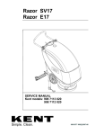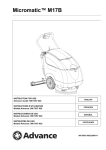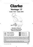
1
Vantage 17 Battery
Order Parts Here:
www.ivie-ent.com/parts
Ph:(918)254-5161
Operator’s Manual
Manuel d’utilisation
Libro de Instrucciones
READ THIS BOOK
EN
English (3 - 27)
LEA ESTE MANUAL
ES
Español (29 - 53)
LISEZ CE MANUEL
FR
Français (55 - 80)
This book has important information for the use and safe operation of this machine. Failure to read
this book prior to operating or attempting any service or maintenance procedure to your Clarke
machine could result in injury to you or to other personnel; damage to the machine or to other
property could occur as well. You must have training in the operation of this machine before using it.
If your operator(s) cannot read this manual, have it explained fully before attempting to operate this
machine.
All directions given in this book are as seen from the operator’s position at the rear of the machine.
For new books write to: Clarke®, 2100 Highway 265, Springdale, Arkansas 72764.
Form No. 909 6772 000 - 05/2006
EN
ENGLISH
TABLE OF CONTENTS
Operator’s Manual
1
OPERATOR SAFETY INSTRUCTIONS
INTRODUCTION
HOW TO KEEP THIS MANUAL
IDENTIFICATION DATA
CHANGES AND IMPROVEMENTS
UNPACKING
MACHINE SPECIFICATIONS
MACHINE TRANSPORT PROCEDURES
SYMBOLS SHOWN ON THE MACHINE
MACHINE DESCRIPTION
OUTER STRUCTURE
INNER STRUCTURE
USE
BATTERY CHECK/SETTING ON A NEW MACHINE
(WET OR GEL) BATTERY SETTING, INSTALLATION AND CHARGING
BEFORE MACHINE START-UP
MACHINE START AND STOP
MACHINE OPERATION (SCRUBBING/DRYING)
MACHINE TRANSPORT/PARKING
TANK EMPTYING
AFTER USING THE MACHINE
RECOVERY TANK REMOVAL
STORED MACHINE
MAINTENANCE
SCHEDULED MAINTENANCE TABLE
SQUEEGEE CLEANING
SQUEEGEE BLADE CHECK AND REPLACEMENT
BRUSH CLEANING
TANK AND VACUUM GRID WITH FLOAT CLEANING OF THE
SOLUTION FILTER CLEANING
MACHINE SPEED ADJUSTMENT
BATTERY CHARGING
FUSE CHECK/REPLACEMENT
Vantage 17 Battery ACCESSORIES/OPTIONS
HOW TO CORRECT PROBLEMS IN THE MACHINE
3
6
6
6
6
6
7
8
9
10
10
11
13
13
14
15
16
17
17
18
18
19
19
20
20
21
21
22
22
23
23
24
25
26
27
Parts List
81
2
Operator’s Manual - Vantage 17 Battery
ENGLISH
EN
OPERATOR SAFETY INSTRUCTIONS
DANGER!
Indicates a dangerous situation (risk of death) for the User.
WARNING!
Indicates the risk for people of being injured and for objects of being damaged.
CAUTION!
Indicates a caution or a remark related to important of useful functions. Pay particular attention
to the paragraphs marked by this symbol.
DANGER!
This machine must be used by properly trained and authorized personnel only. Children or
disabled people cannot use this machine.
DANGER!
When using lead (WET) batteries, battery charging produces highly explosive hydrogen gas.
During battery charging, remove the recovery tank assembly and perform this operation in
well-ventilated areas and away from naked flames. Do not smoke near the machine while charging
the batteries.
DANGER!
When using lead (WET) batteries, keep sparks, flames and incandescent materials away from the
batteries. During normal operation, explosive gases are released.
DANGER!
Do not operate the machine near toxic, dangerous, inflammable and/or explosive powders,
liquids or vapours.
DANGER!
Disconnect the batteries before performing any maintenance/repair procedure.
DANGER!
Do not wear jewels when working near electrical components.
WARNING!
Before connecting the battery charger to the electrical mains, be sure that frequency and voltage
indicated in the related Manual correspond to the mains voltage.
WARNING!
Do not charge batteries with damaged battery charger cable or plug. If the machine is not working
as it should, has been damaged, left outdoors or dropped into water, return it to the Service
Center.
WARNING!
Do not pull or carry the machine by the battery charger cable; never use the battery charger cable
as a handle. Do not close a door on the supply cable, or pull the supply cable around sharp edges
or corners. Do not run the machine on the battery charger cable.
Keep the battery charger cable away from heated surfaces.
WARNING!
To reduce the risk of fire, electric shock, or injury, do not leave the machine unattended when it
is plugged in.
WARNING!
To avoid electric shock, do not expose to rain. Store the machine indoors.
WARNING!
Do not allow to be used as a toy. Close attention is necessary when used near children.
WARNING!
Use only as described in this Manual. Use only Clarke recommended accessories.
WARNING!
Take all necessary precautions to prevent hair, jewerly and loose clothing from being caught in
the machine moving parts or vacuuming parts of the machine.
WARNING!
Do not leave the machine unattended without being sure that the machine cannot move
independently.
Operator’s Manual - Vantage 17 Battery
3
EN
4
ENGLISH
WARNING!
Do not use the machine on slopes with a gradient exceeding the specifications.
WARNING!
Do not allow any object to enter into the openings. Do not use the machine if the openings are
clogged; always keep the openings free from dust, hair and any other foreign material which
could reduce the air flow.
WARNING!
While using this machine, take care not to cause damage to people.
WARNING!
Do not use the machine in particularly dusty areas.
WARNING!
Do not put any can containing fluids on the machine.
WARNING!
The machine working temperature must be between +32°F and +104°F (0°C and +40°C).
The storage temperature must be between +32°F and +104°F (0°C and +40°C).
The humidity must be between 30% and 95%.
WARNING!
Always protect the machine against the sun, rain and bad weather, both under operation and
inactivity condition.
WARNING!
Do not use the machine as a means of transport.
WARNING!
Do not use the machine on slopes with an inclination higher than 2%.
WARNING!
Do not allow the brush to operate while the machine is stationary to avoid damaging the floor.
WARNING!
Do not bump into shelves or scaffoldings, particularly where there is a risk of falling objects.
WARNING!
Do not tamper with the machine safety guards and follow the ordinary maintenance instructions.
WARNING!
Do not remove or modify the plates affixed to the machine.
WARNING!
In case of fire, use a powder fire extinguisher, not a water one.
WARNING!
To ensure the proper and safe operation of the machine, have the scheduled maintenance and
repair, detailed in the relevant chapter of this Manual, performed by the authorized personnel or
an authorized Service Center.
WARNING!
If parts must be replaced, require GENUINE spare parts from a Dealer or Authorized Retailer.
WARNING!
Do not wash the machine with direct or pressurised water jets, or with corrosive substances.
WARNING!
The machine must be disposed of properly, because of the presence of toxic-harmful materials
(batteries, electronic boards etc.), which are subject to standards that require disposal in special
centers (see Scrapping chapter).
WARNING!
If the machine is used according to the instructions, the vibrations do not cause dangerous
situations. The machine vibration level is under 98.42 in/s2 (2.5 m/s2).
WARNING!
Pay attention during the machine transfers when temperature is below freezing point. The water
in the recovery tank or in the hoses could freeze and seriously damage the machine.
Operator’s Manual - Vantage 17 Battery
ENGLISH
EN
WARNING!
Use the brushes and the pads supplied with the machine and those specified in the Operator’s
Manual. Using other brushes or pads could reduce safety.
CAUTION!
This machine contains lead acid batteries. The batteries must be disposed of in an
environmentally acceptable manner.
Operator’s Manual - Vantage 17 Battery
5
EN
ENGLISH
INTRODUCTION
The model of the Clarke scrubber-dryer ensures a highly effective floor cleaning performance. The Vantage 17 Battery model
uses a single rotary brush to clean an area of 17.0 in (430 mm) in width. The rear squeegee performs the floor cleaning and
the vacuum system recovers the washing water in a single pass.
HOW TO KEEP THIS MANUAL
The Instructions for Operator’s Manual must be kept near the machine, inside an adequate case, away from liquids and other
substances that can cause damage to it.
IDENTIFICATION DATA
The machine serial number and model are shown on the plate and can be read from the outside. (A, Fig. 2 - pag 10)
The machine model year is written in the Declaration of Conformity and it is also indicated by the first two figures of the machine
serial number.
This information is useful when requiring machine spare parts. Use the following table to write down the machine identification
data for any further reference.
MACHINE Model: ______________________________
MACHINE Serial Number: _______________________
CHANGES AND IMPROVEMENTS
Clarke constantly improves its products and reserves the right to make changes and improvements at its discretion without
being obliged to apply such benefits to the machines previously sold.
Any change and/or addition of accessories must be approved and performed by Clarke.
UNPACKING
To unpack the machine carefully follow the instructions on the packing.
When the machine is delivered, check that the packing and the machine were not damaged during transportation. In case of
visible damages, keep the packing and have it checked by the Carrier that delivered it. Call the Carrier immediately to fill in a
damage claim.
Please check that the following items have been supplied with the machine:
1. Technical documents:
– Scrubber-dryer operator's manual
– Electronic battery charger manual
2. 40A fuse
3. battery panels
6
Operator’s Manual - Vantage 17 Battery
ENGLISH
EN
MACHINE SPECIFICATIONS
Model
Vantage 17 Battery
Working Voltage
Standard Batteries (Quantity: 2)
Battery rating (80 Ah)
Drive Speed
Battery Protection System
Vacuum Motor
Vacuum System Capacity
24 V
12V 70 Ah, GEL
20 hr
Determined by brush rotation
Low Voltage Cut-Off of Brush and Solution
330 W
41.5 in H2O (1,055 mm H2O)
Solution Tank Capacity
8.2 gal (31 liters)
Solution Flow (min/max)
0.08/0.26 gal/min (0.3/1.0 liters/min)
Recovery Tank Capacity
7.7 gal (29 liters)
Squeegee
Squeegee Width
Cleaning Width
Brush/Pad Motor
Brush/Pad Diameter
Brush/Pad Rotation Speed
Straight
28.3 in (720 mm)
17 in (430 mm)
520 W
17 in (430 mm)
135 RPM
Brush/Pad On-Floor Pressure (with Full Tank)
50.6 lbs (23 kg)
Central Wheels on Fixed Axle Diameter
9.8 in (250 mm)
Pivoting Wheel (diameter)
1.9 in (49 mm)
Wheel Pressure on the Ground
Less than 0.37 ft/lbs2 (0.5 N/mm2)
On-Board Battery Charger
24V D.C., 8 Amp., 115-230V, 50-60 Hz
Maximum Floor Inclination
2%
Machine Length
43.9 in (1115 mm)
Machine Width (without Squeegee)
22.4 in (570 mm)
Machine Height
41.4 in (1050 mm)
Machine Weight with Batteries, Brush and Full Solution
Tank (Working Condition)
346.1 lbs (157 kg)
Sound Pressure Level (at the Operator's Position)
Battery Compartment Size (Length x Width x Height)
Operator’s Manual - Vantage 17 Battery
67 dB(A)
13.8x13.8x10.2 in (350x350x260 mm)
7
EN
ENGLISH
MACHINE TRANSPORT PROCEDURES
How to Load and Unload the Machine from a Van or a
Truck
WARNING!
This machine is heavy. Machine transfer must be
performed by qualified personnel only. Machine
transfer on steep ramps must be performed by two
well-trained operators only. Always move it slowly.
Do not turn the machine on slopes. Do not leave the
machine unattended on slopes. Loading ramp width
must not be less than 40 in (1 m).
1.
2.
3.
4.
Check that the loading ramp is not longer than 8 feet (2.5
m) and not wider than 40 inches (1 m). Its thickness must
be adequate to support the machine and operators'
weight.
Check that the ramp is dry and clean.
Position the ramp properly.
Before loading the machine, remove the squeegee
assembly and the brush/pad holder. Before loading the
machine, empty both the solution and the recovery tank.
How to Fasten the Machine Inside the Vehicle
5.
Clarke recommends
transporting.
tying
down
machine
when
Figure 1
8
Operator’s Manual - Vantage 17 Battery
ENGLISH
EN
SYMBOLS SHOWN ON THE MACHINE
WARNING!
Carefully
read
all
maintenance/repair
maintenance/repair procedure.
instructions
before
performing
any
WARNING!
Do not wash the machine with pressurized water.
WARNING!
Do not open the cover. Electric danger!
Operator’s Manual - Vantage 17 Battery
9
EN
ENGLISH
MACHINE DESCRIPTION
OUTER STRUCTURE
(See Fig. 2)
A.
B.
C.
D.
E1.
E2.
F.
G.
H.
I.
J.
K.
L.
M.
N.
O.
P.
Serial number plate/technical data
Handlebar
Control panel
Solution flow control lever
ECO Solution Flow Position
Maximum solution flow position
Recovery tank cover
Rear support wheel for transport/parking
Central wheels on fixed axle
Brush/pad-holder with pad
Brush/pad-holder cover
Squeegee
Squeegee knobs
Front squeegee blade
Rear squeegee blade
Squeegee blade fixing springs
Recovery tank drain hose
Q. Recovery tank drain hose bracket
R. Solution drain valve
S. Squeegee lifting/lowering lever
T. Solution filter
U. Battery charger cable
V. Squeegee vacuum hose
W. Transport/parking device
W1. Transport/parking device activated
W2. Transport/parking device deactivated
X. Transport/parking device positioning pin
Y. Electrical component box
Z. Battery charger
AA. Battery charger warning lights
AB. Battery installation diagram
AC. Recovery tank
AD. Solution tank
F
C S
AC
B
Q
AD
P
AB
U
AA
A
R
Z
E1
E2
X
Y
V L
W
J
W1
I
H T
M
O
DG
W2
O
N
K
M
N
Figure 2
10
Operator’s Manual - Vantage 17 Battery
ENGLISH
EN
INNER STRUCTURE
(See Fig. 3)
A.
B.
C.
D.
E.
F.
G.
H.
I.
J.
Recovery tank cover (open)
Recovery tank cover gasket
Cover stand (applied)
Recovery tank
Solution tank
Vacuum grid with automatic shut-off float
Recovery water drain hole
Vacuum motor
Brush/pad motor
Batteries
K.
L.
M.
N.
O.
P.
Q.
Battery installation diagram
Cover with brush/pad-holder coupling pin
Machine speed adjusting screw
Brush
Pad-holder
Pad
Vent hole
A
B
C
K
D
J
E
Q
F
G
H
L
M
N
O
I
P
Figure 3
Operator’s Manual - Vantage 17 Battery
11
EN
ENGLISH
CONTROL PANEL
(See Fig. 4)
Charged Battery Indicator Light (Green) (A, Fig. 4)
When it turns on, it indicates that the batteries are charged.
Half-discharged Battery Indicator Light (Yellow) (B, Fig. 4)
When it turns on, it indicates that the batteries are half discharged.
Discharged Battery Indicator Light (Red) (C, Fig. 4)
When it turns on, it indicates that the batteries are discharged. Do not use the machine with discharged batteries, to avoid
damaging the batteries, but charge them (see the procedure in the Maintenance chapter).
Brush/Pad Rotation Switch (D, Fig. 4)
When it is turned to the "I" position, the machine is ready to start the brush/pad rotation. To start the brush/pad rotation, press
and hold one or both the activation switches (F, Fig. 4).
When it is turned to the "0" position, the brush/pad rotation is deactivated.
Water Vacuuming Switch (E, Fig. 4)
When it is turned to the "I" position, it starts the vacuuming of the recovery water.
When it is turned to the "0" position, it stops the vacuuming of the recovery water.
Activation Switches (F, Fig. 4)
When one or both the activation switches are pressed, the brush/pad rotation is activated.
The switches are active only if the brush/pad rotation switch (D, Fig. 4) is turned to the "I" position.
A
F
B
C
E
D
F
Figure 4
12
Operator’s Manual - Vantage 17 Battery
ENGLISH
EN
B
USE
A
WARNING!
On some points of the machine there are some
labels indicating:
– DANGER
– WARNING
– CAUTION
– INFORMATION
While reading this Manual, the Operator must pay particular
attention to the symbols shown in the plates.
Do not cover these plates for any reason and immediately
replace them if damaged.
BATTERY CHECK/SETTING ON A NEW MACHINE
WARNING!
The electric components of this machine can be
seriously damaged if batteries are either installed or
connected improperly. The batteries must be
installed by qualified personnel only.
Check the batteries for damage before installation.
Handle the batteries with great care.
Install the battery terminal caps supplied with the
machine.
Figure 5
The machine is supplied with GEL batteries already
installed and ready to be used.
–
Turn the brush/pad rotation switch and the water
vacuuming switch (A and B, Fig. 6) to the "I" position. If
the green warning light (C) turns on, the batteries are
ready to be used.
–
If the yellow or red warning light (D or E, Fig. 6) turns on,
it is necessary to charge the batteries before using the
machine (see the procedure in the Maintenance
chapter).
C
D
E
B
A
Figure 6
Operator’s Manual - Vantage 17 Battery
13
EN
ENGLISH
(WET
OR
GEL)
BATTERY
INSTALLATION AND CHARGING
SETTING,
D
The electrical board of the machine is to be set according to
the type of batteries installed, either gel (GEL) or lead (WET).
Proceed as follows:
C
Machine Setting
1.
2.
3.
The machine factory setting is for GEL batteries; if this
setting corresponds to the type of batteries bought, go to
step 5. Otherwise, carry out steps 2, 3, and 4 too.
Remove the screws (A, Fig. 7) and carefully pull out the
electrical component box cover (B).
Push the microswitch (C, Fig. 7) downwards to WET
position.
A
B
A
WARNING
Do not move the adjacent switch (D, Fig. 7).
4.
A
A
Figure 7
Reinstall the electrical component box cover (B, Fig. 7)
and tighten the screws (A).
Battery Installation
D
5.
Disconnect the vacuum hose (A, Fig. 8) from the
squeegee (B).
6. Disconnect the recovery tank drain hose (C, Fig. 8) from
the bracket (D).
7. Open the cover (A, Fig. 9) and apply the cover stand (B).
8. Grasp the recovery tank (C, Fig. 9) in the area (D) and lift
it, as shown in the figure, then disconnect the vacuum
hose (E) from the tank and remove the tank (C) together
with the hoses (F) and (G).
9. Install the batteries on the machine according to the
diagram (E, Fig. 8).
10. Reinstall the tank (C, Fig. 9) by carrying out steps 5 to 9
in the reverse order.
C
E
A
B
Battery Charging
11. Charge the batteries (see the relevant procedure in the
Maintenance chapter).
Figure 8
D
E
C
G
A
F
B
Figure 9
14
Operator’s Manual - Vantage 17 Battery
ENGLISH
EN
BEFORE MACHINE START-UP
To prepare the machine for operation, follow this procedure
before start-up.
Squeegee Installation
1.
C
Install the squeegee (A, Fig. 10) and fix it by means of the
squeegee knobs (B), then connect the vacuum hose (C)
to the squeegee.
B
Solution Tank Filling
2.
Fill the solution tank (A, Fig. 11) with a solution suitable
for the work to be carried out.
Do not fill the solution tank completely, leave few inches
from the edge.
Always follow the dilution instructions on the container
label on the chemical product used to create the solution.
The solution temperature must not exceed 100°F (40°C).
A
Figure 10
A
CAUTION
Use only low-foam and non-flammable liquid
detergents, intended for automatic scrubber
applications.
Brush or Pad-Holder Installation
NOTE
According to the kind of cleaning to be carried out,
the machine can be equipped both with the brush (B,
Fig. 11) and the pad-holder (C) with pad (D).
3.
4.
5.
6.
7.
C
B
D
Deactivate the transport/parking device (A, Fig. 12) by
putting it in position (B) after inserting the relevant pin (C).
Lift the brush cover (D, Fig. 12) by prying the handlebar
(E).
Place the brush (B, Fig. 11) or the pad-holder (C) with
pad (D) under the cover.
Lower the cover (D, Fig. 12) by means of the handlebar
(E).
Press the brush push-button on “I” (Fig. 12, F), then press
on or both push-buttons (Fig. 12, G) for a few seconds.
If the hooking operation is difficult, manually rotate the
brush/pad-holder counterclockwise (Fig. 13).
Figure 11
F
E
G
C
A D
Figure 13
B
Figure 12
Operator’s Manual - Vantage 17 Battery
15
EN
ENGLISH
MACHINE START AND STOP
C
Start
1.
2.
3.
4.
D
Prepare the machine according to the procedure shown
in the previous paragraph.
Lower the squeegee (A, Fig. 15) by pushing the lever (B)
downwards.
Turn the solution flow control lever (C, Fig. 15) to one of
the following positions, according to the type of cleaning
to be carried out:
– ECO system: When the lever (C, Fig. 15) is in the
"ECO" position (D), the machine works in a special
condition of programmed water "economy" usage; as
the water flow is set and constant, the machine can
work with a cleaning time of 70-80 minutes [0.08
gal/min (0.3 liters/min].
– Variable system: When the lever is turned to the left
(variable flow), it is possible to increase the capacity
up to 0.26 gal/min (1 liter/min) (E, Fig. 15).
During machine operation, it is not possible to completely
close the water flow to the brush/pad.
Turn the switches (A and B, Fig. 14) to the "I" position.
E
B
A
Figure 14
G
F
NOTE
If the green indicator light (C, Fig. 14) turns on, the
machine is ready to be used.
If the yellow (D) or red indicator light (E) turns on, it
is necessary to charge the batteries (see the
procedure in the Maintenance chapter).
5.
F
B
While keeping both hands on the handlebar (G, Fig. 15),
start the machine by pressing one or both the activation
switches (F).
D
E
Machine Stop
6.
7.
8.
9.
Release the switches (F, Fig. 15).
Turn the switches (A and B, Fig. 14) to the "0" position.
Lift the squeegee by pushing the lever (B, Fig. 15)
completely upwards.
Lift the brush/pad by activating (B, Fig. 16) the
transport/parking device (A) after inserting the relevant
pin (C).
A
C
Figure 15
C
A
B
Figure 16
16
Operator’s Manual - Vantage 17 Battery
EN
ENGLISH
MACHINE OPERATION (SCRUBBING/DRYING)
1.
2.
A
Start the machine according to the procedure shown in
the previous paragraph.
While keeping both hands on the handlebar (D, Fig. 18),
move the machine and start scrubbing/drying the floor.
B
C
CAUTION:
To avoid damaging the floor surface:
– Do not use the brush/pad without the solution.
– When the machine is stopped, stop the
brush/pad by releasing the switches (A, Fig. 18).
E
CAUTION:
Before lifting the brush/pad, stop its rotation by
releasing the switches (A, Fig. 18).
3.
D
Figure 17
If necessary, adjust the solution flow sent to the
brush/pad by turning the lever (B, Fig. 18).
A
Battery Discharge During Operation
4.
A
D
Until the green indicator light (A, Fig. 17) stays on, the
batteries allow the machine to operate normally.
When the green indicator light (A) turns off and the yellow
(B) and red (C) warning indicator lights turn on in
sequence, it is necessary to charge the batteries.
C
CAUTION:
Do not use the machine with discharged batteries, to
avoid damaging the batteries and reducing the
battery life.
Machine Speed Adjustment
5.
The machine speed depends on the type of floor to be
cleaned and on the choice of using brush or pad.
If necessary, it is possible to adjust the machine speed by
following the relevant procedure in the Maintenance
chapter.
MACHINE TRANSPORT/PARKING
After operation, proceed as follows to transport/park the
machine.
1. Turn the brush/pad rotation switch and the water
vacuuming switch (D and E, Fig. 17) to the "0" position.
2. Lift the squeegee by pushing the lever (C, Fig. 18)
upwards.
3. Grasp the handlebar (A, Fig. 19) and slightly lower it until
the rear wheel (B) comes into contact with the floor, as
shown in the figure. While holding the machine in this
position, push it to the transport/parking area.
B
Figure 18
A
B
Figure 19
Operator’s Manual - Vantage 17 Battery
17
EN
ENGLISH
TANK EMPTYING
An automatic float shut-off system (A, Fig. 20) deactivates the
vacuum system once the recovery tank (B) is full.
The vacuum system shutdown is due to the recovery tank
filling, which prevents recovery water from being vacuumed,
and it is signalled by a sudden increase in the system motor
noise frequency.
When the recovery tank (B, Fig. 20) is full, empty it according
to the following procedure.
Recovery Tank Emptying
1.
2.
3.
4.
5.
B
Stop the machine by turning the brush/pad rotation
switch and the water vacuuming switch (A and B, Fig. 21)
to the "0" position.
Lift the squeegee by means of the lever (C, Fig. 21).
Push the machine to the appointed disposal area.
Insert the positioning pin (E), lift the brush/pad and
activate the transport/parking device (D, Fig. 21) by
means of the handlebar.
Disconnect the recovery tank drain hose (F, Fig. 21) from
the bracket (G); open the cover (H), then lower the hose
(F) and empty the recovery tank. Then, rinse the tank
with clean water.
A
C
Solution Tank Emptying
6.
7.
Carry out steps 1 to 4.
Empty the solution tank by opening the drain valve (I, Fig.
21). Then, rinse the tank with clean water.
AFTER USING THE MACHINE
Figure 20
After scrubbing-drying, before leaving the machine:
1. Remove the brush/pad-holder as follows:
– Turn the brush/pad rotation switch (A, Fig. 21) to the
"I" position.
– Lift the brush/pad-holder and press one or both the
switches (J, Fig. 21) for a few seconds, then release
them: this causes the brush/pad-holder to be
disengaged.
2. Empty the tanks (B and C, Fig. 20) according to the
procedure shown in the previous paragraph.
3. Perform the maintenance operations to be carried out
after using the machine (see the Maintenance chapter).
4. Store the machine in a clean and dry place, with the
brush/pad and the squeegee lifted or removed.
J
A
B
C
H
G
F
K
E
D
L
I
Figure 21
18
Operator’s Manual - Vantage 17 Battery
EN
ENGLISH
RECOVERY TANK REMOVAL
A B
To check the batteries, or to perform other operations, it may
be necessary to remove the recovery tank (A, Fig. 23)
according to the following procedure:
1. Empty the tank (A, Fig. 23) according to the procedure
shown in the relevant paragraph.
2. Drive the machine on a level ground.
3. Make sure that the switches (A and B, Fig. 22) are in the
"0" position.
4. Disconnect the vacuum hose (C, Fig. 22) from the
squeegee (D).
5. Disconnect the recovery tank drain hose (E, Fig. 22) from
the bracket (F).
6. Open the cover (B, Fig. 23) and apply the cover stand
(C).
7. Grasp the recovery tank (A, Fig. 23) in the area (D) and
slightly lift it, as shown in the figure.
8. Disconnect the vacuum hose (E, Fig. 23) from the tank,
then remove the tank (A) with the hoses (F) and (G).
F
E
C
STORED MACHINE
If the machine is not going to be used for more than 30 days,
proceed as follows:
1. Perform the operations described in the After Using the
Machine paragraph.
2. Remove the recovery tank (A, Fig. 23) according to the
procedure shown in the previous paragraph, then
disconnect the battery negative terminals.
3. Reinstall the recovery tank (A, Fig. 23).
4. Store the machine in a clean and dry place, with the
brush/pad and the squeegee lifted or removed.
D
Figure 22
D
E
A
B
G
F
C
Figure 23
Operator’s Manual - Vantage 17 Battery
19
EN
ENGLISH
MAINTENANCE
WARNING!
All maintenance operations must be performed by qualified personnel, or by an authorized Service Center.
WARNING!
Maintenance operations must be carried out:
– With the machine switched off
– With the battery disconnected
– With the battery charger-electrical mains connecting cable disconnected
Moreover, read carefully the instructions in the Operator Safety Instructions chapter before performing any
maintenance operation.
The lifespan of the machine and its maximum operating safety are ensured by correct and regular maintenance.
Provided below is the Scheduled Maintenance Table. The intervals shown may vary according to particular working conditions,
which are to be defined by the person in charge of the maintenance.
This Manual contains the Scheduled Maintenance Table and describes only the easiest and most common maintenance
procedures.
SCHEDULED MAINTENANCE TABLE
Procedure
Daily or after
using the
machine
Squeegee Cleaning
z
Brush Cleaning
z
Tank and Vacuum Grid with Float Cleaning
z
Battery Charging
z
Weekly
Squeegee Blade Check and Replacement
z
Solution Filter Cleaning
z
Every six
months
Yearly
z (1)
Screw and Nut Tightening Check
Brush Motor Carbon Brush Check or Replacement
z (2)
Vacuum Motor Carbon Brush Check or Replacement
z (2)
(1): and after the first 8 working hours
(2): for these maintenance operations, contact an authorized Clarke Service Center
20
Operator’s Manual - Vantage 17 Battery
EN
ENGLISH
SQUEEGEE CLEANING
A
NOTE
The squeegee must be clean and the blades must be
in good condition in order for the floor to dry
properly.
B
CAUTION
It is advisable to use protective gloves when
cleaning the squeegee because there may be cutting
debris.
1.
2.
3.
4.
5.
6.
7.
C
Make sure that the switches (A and B, Fig. 24) are in the
"0" position.
Lower the squeegee (D, Fig. 24) by means of the lever
(C).
Disconnect the vacuum hose (E, Fig. 24) from the
squeegee.
Loosen the squeegee knobs (F, Fig. 24) and remove the
squeegee (D).
Wash and clean the squeegee assembly to remove dirt
and debris.
Check the front blade (C, Fig. 25) and the rear blade (D)
for wear, cuts and tears; if required, replace them
according to the procedure in the “Squeegee Blade
Check and Replacement“ section below.
Reassemble in the reverse order of disassembly.
E
D
SQUEEGEE BLADE CHECK AND REPLACEMENT
1.
2.
3.
4.
5.
Clean the squeegee according to the procedure shown in
the previous paragraph.
Check that the edge (E, Fig. 25) of the front blade and the
edge (F) of the rear blade lay down on the same level,
along their length; otherwise adjust their height according
to the following procedure:
– Remove the fixing springs (G, Fig. 25) and adjust the
front blade (C) and the rear blade (D).
– Reinstall the fixing springs on the properly adjusted
front and rear blades.
Check the front blade (C, Fig. 25) and rear blade (D) for
wear, cuts and tears. If necessary, replace them
according to the following procedure:
– Remove the spring clamp (G, Fig. 25) and replace the
blade.
F
Figure 24
D
A
B
C
G
A
G
NOTE: When replacing the blades, make sure that
the ribs of the front blade face the front and the ribs
of the rear blade face the rear.
– Reinstall the spring clamps (G, Fig. 25).
Reinstall the squeegee (D, Fig. 24) and screw down the
squeegee knobs (F).
Connect the vacuum hose (E, Fig. 24) to the squeegee
(D).
C
D
E
H F
I
Figure 25
Operator’s Manual - Vantage 17 Battery
21
EN
ENGLISH
BRUSH CLEANING
A B
CAUTION
It is advisable to use protective gloves when
cleaning the brush because there may be cutting
debris.
1.
2.
3.
Remove the brush from the machine, according to the
procedure shown in the Use chapter.
Clean and wash the brush with water and detergent.
Check the brush bristles for integrity and wear; if
necessary, replace the brush.
C
CLEANING OF THE TANK AND VACUUM GRID
FLOAT
1.
2.
3.
4.
5.
Push the machine to the appointed disposal area.
Make sure that the switches (A and B, Fig. 26) are in the
"0" position.
Lift the cover (A, Fig. 27) and apply the cover stand (B),
then clean and wash the cover, the tanks (C and D) and
the vacuum grid (E) with clean water.
Drain the water from the tanks by means of the drain
hose (C, Fig. 26) and valve (D).
If necessary, release the retainers (F, Fig. 27), open the
vacuum grid (E), remove the float (G), then carefully
clean and reinstall them.
Check the cover sealing gasket (H, Fig. 27) of the
recovery tank for wear.
NOTE
The gasket (H, Fig. 27) creates vacuum in the tank,
which is necessary for the vacuuming of the
recovery water.
6.
7.
Figure 26
H
E
F
G
I
F
If necessary, replace the gasket (H, Fig. 27) after
removing it from the housing (I).
When reassembling the new gasket, install the joint (J) in
the central area, as shown in Fig. 27.
Check the gasket (H, Fig. 27) seating surface (K) for
integrity and sealing capabilities.
Check the vent hole (L, Fig. 27). If clogged, clean it.
NOTE
The hole (L, Fig. 27) compensates the air in the cover
interspaces, thus allowing the creation of vacuum in
the recovery tank.
8.
D
A
H
J
B
K
Remove the cover stand (B, Fig. 27) and close the cover
(A).
C
D
L
Figure 27
22
Operator’s Manual - Vantage 17 Battery
ENGLISH
SOLUTION FILTER CLEANING
1.
2.
3.
4.
B
Empty the solution tank (A, Fig. 28) according to the
procedure shown in the relevant paragraph.
Drive the machine on a level ground.
Make sure that the switches (B and C, Fig. 28) are in the
"0" position.
Remove the transparent cover (D, Fig. 28) and the filter
strainer (E), then clean and reinstall them on the support
(F).
EN
C
A
NOTE
Properly install the strainer (E, Fig. 28) in the
housing (G) of the support (F).
MACHINE SPEED ADJUSTMENT
NOTE
The machine speed depends on the type of floor to
be cleaned and on the choice of using brush or pad.
The machine speed can be adjusted according to
the following procedure.
1.
2.
3.
4.
F
Remove the recovery tank as shown in the Use chapter.
Adjust the machine speed by means of the screw (A, Fig.
29), according to the following procedure:
– Loosen the screw (B, Fig. 29) on the right side of the
machine, by turning it counter-clockwise.
– Turn
the
adjusting
screw
(A,
Fig.
29)
counter-clockwise to increase the machine speed.
– Turn the adjusting screw (A, Fig. 29) clockwise to
decrease the machine speed.
– After adjusting, tighten the screw (B, Fig. 29).
Install the recovery tank as shown in the Use chapter.
With the machine ready to operate, carry out hands-on
tests of the machine speed and, if other adjustments are
necessary, repeat steps 1 to 4.
E
D
G
E
Figure 28
A
B
Figure 29
Operator’s Manual - Vantage 17 Battery
23
EN
ENGLISH
BATTERY CHARGING
NOTE
Charge the batteries when the indicator light (A or B,
Fig. 30) turns on, or when finished cleaning.
Keeping the batteries charged makes them last
longer.
A
B
CAUTION
When the batteries are discharged, charge them as
soon as possible, as that condition makes them last
shorter.
Check for battery charge at least once a week.
CAUTION!
Batteries must be charged indoors, in a dry
environment.
1.
2.
24
Figure 30
Drive the machine indoors, in a dry environment (damp
free), to charge the batteries.
Charge the batteries according to the following
procedure.
Operator’s Manual - Vantage 17 Battery
EN
ENGLISH
3.
Make sure the battery charger cable is plugged into an
electrical outlet that will provide voltage and frequency
according to the serial number plate/technical data (D,
Fig. 31).
NOTE
When the battery charger is connected to the
electrical outlet, all machine functions are
automatically cut off.
The green indicator light (B, Fig. 31) flashes when
the battery charger is charging the batteries.
4.
5.
6.
When the green indicator light (B, Fig. 31) stays on, the
battery charging cycle is over.
When the battery charging cycle is over, disconnect the
battery charger cable (A, Fig. 31) from the electrical outlet
and wind it around it’s housing on the machine.
Now the machine is ready to be used.
NOTE
For further information about the operation of the
battery charger (C, Fig. 31), see the relevant Manual.
B
C
D
A
FUSE CHECK/REPLACEMENT
1.
2.
3.
4.
5.
Remove the recovery tank as shown in the Use chapter.
Disconnect the battery negative terminal.
Remove the screws (A, Fig. 32) and remove the electrical
component box cover (B).
Check/replace the fuses:
– Brush fuse (C, Fig. 32): (40 A)
– Vacuum system fuse (D, Fig. 32): (40 A)
– Solenoid valve and electronic board fuse (E, Fig. 32):
(5 A)
Reassemble in the reverse order of disassembly.
Figure 31
E
A
D
C
B
A
Figure 32
Operator’s Manual - Vantage 17 Battery
25
EN
ENGLISH
Vantage 17 Battery ACCESSORIES/OPTIONS
In addition to the standard components, the machine can be equipped with the following accessories/options, according the
machine specific use:
For further information concerning the above-mentioned optional accessories, contact an authorized Retailer.
ACCESSORIES/OPTIONS
See “Parts List” section.
909 5691 000
Brush, 17" Midlite Grit 180
08812891
Brush, 17" Poly
909 5695 000
Pad Holder 410
08603966
Ring Nylon
26
Operator’s Manual - Vantage 17 Battery
ENGLISH
EN
HOW TO CORRECT PROBLEMS IN THE MACHINE
PROBLEM
POSSIBLE CAUSE
ACTION
Disconnected or dirty battery terminals
Connect or clean the battery terminals
Completely discharged batteries
Charge the batteries
Blown fuse
Replace the fuse
Full recovery tank
Empty the tank
Clogged vacuum grid or stuck closed
float
Clean the vacuum grid and the float
Vacuum hose disconnected from the
squeegee or faulty
Connect or repair/replace it
Dirty squeegee, or worn or damaged
squeegee blades
Clean the squeegee or replace the
blades
Improperly closed recovery tank cover
or worn gasket or clogged vent hole
Correctly close the cover or replace the
gasket or clean the vent hole
Dirty solution filter
Clean the filter
Clogged recovery tank output hole
Clean the hole
Debris under the squeegee blades
Remove the debris
The motors do not work
Vacuum motor does not run.
Insufficient recovery water vacuuming
Insufficient solution flow to the brushes
The squeegee leaves lining on the floor
streaks.
Worn, chipped or torn squeegee blades Replace the blades
Operator’s Manual - Vantage 17 Battery
27
Vantage 17 Battery
Parts List
[] = Not shown
* = optional
# = Modified item No. or New item No.
xxxxx = Contained in a Kit
Form No. 909 6772 000 - 05/2006
Printed in Italy
Vantage 17 Battery
Solution Tank
8
35
15
36
17 14
7
10
19 11
31
33
24
12
5
6
34
29
21
38
2
3
37
30
28
13
9
26
16
1
18
20
25
32
27
39
23
4
22
82
Parts list - Vantage 17 Battery
Vantage 17 Battery
Solution Tank
Ref.
Part No.
Description
Qty
1
xxxxxxxx
Washer flat 6X18 (Solution tank hardware kit)
2
2
xxxxxxxx
Clamp (Solution tank hardware kit)
1
3
xxxxxxxx
Screw M5X10 (Solution tank hardware kit)
5
4
088603258
Washer flat 11X16
1
5
xxxxxxxx
Nut hex. low self lock M6 SS (Kit squeegee lift cable)
1
6
xxxxxxxx
Washer flat 6X18 SS (Kit squeegee lift cable)
2
7
08603845
Cable clamp
1
8
xxxxxxxx
Knob (Kit squeegee lift cable)
1
9
08812392
Spacer
2
10
xxx xxxx xxx
Ball joint (Kit squeegee lift cable)
1
11
xxxxxxxx
Hose clamp (Solution tank hardware kit)
1
12
xxx xxxx xxx
Screw hex hd M6X20 SS (Kit squeegee lift cable)
1
13
xxx xxxx xxx
Screw M8X20 (Solution tank hardware kit)
2
14
xxx xxxx xxx
Washer flat 8X17 (Kit squeegee lift cable - Solution tank
hardware kit)
1
15
xxx xxxx xxx
Washer flat 6X12,5 (Kit squeegee lift cable - Solution tank
hardware kit)
2
16
xxx xxxx xxx
Retaining ring (Solution tank hardware kit)
2
17
xxx xxxx xxx
Nut hex. self lock M8 (Kit squeegee lift cable - Solution tank
hardware kit)
1
18
xxx xxxx xxx
Washer split (Solution tank hardware kit)
2
19
xxx xxxx xxx
Screw M5X12 (Solution tank hardware kit)
1
2
20
xxx xxxx xxx
Screw hex hd M6X16 (Solution tank hardware kit)
21
xxx xxxx xxx
Washer flat 16X30 (Solution tank hardware kit)
6
22
xxx xxxx xxx
Nut hex. self lock M10 (Solution tank hardware kit)
1
23
909 5560 000
Wheel
1
24
909 5606 000
Clamp
2
25
909 5641 000
Indexing plunger
1
26
909 5649 000
Support
1
27
909 5658 000
Supporting rod
1
28
909 5696 000
Valve
1
29
909 5748 000
Wheels shaft
1
30
909 5895 000
Elbow 90° ø10
1
31
909 6271 000
Solution tank
1
32
909 6281 000
Wheel
2
33
909 6283 000
Squeegee lifting cable (Kit squeegee lift cable)
1
34
909 6821 000
Decal Clarke Vantage17 Battery (Kit decals)
3
35
909 6437 000
Kit squeegee lift cable (5,6,8,10,12,14,15,17,33,36)
1
36
xxx xxxx xxx
Squeegee lifting lever (Kit squeegee lift cable)
1
37
909 5286 000
Gasket
2
38
xxx xxxx xxx
Spacer (Solution tank hardware kit)
2
39
909 6441 000
Pin 3X20
1
[40]
909 6438 000
Solution tank hardware kit
(1,2,3,11,13,14,15,16,17,18,19,20,21,22,38)
1
Parts list - Vantage 17 Battery
83
Vantage 17 Battery
Vacuum System
8
9
2
1
4
7
6
3
5
84
Parts list - Vantage 17 Battery
Vantage 17 Battery
Vacuum System
Ref.
Part No.
Description
Qty
1
08228600
Washer falt 6x18 (Vacuum systems hardware kit)
2
08603706
Screw cyl hd M6x12 (Vacuum systems hardware kit)
15
3
3
909 5371 000
Carbon brush
2
4
909 5198 000
Vibration damping M6
3
5
909 5564 000
Pipe acoustic insulation
1
6
909 5565 000
Pipe acoustic insulation
1
7
909 5713 000
Kit vacuum motor with connector
1
8
909 6290 000
Vacuum motor hose
1
9
146 0104 00
Hose clamp
1
[10]
909 5987 000
Vacuum systems hardware kit (1,2)
1
Parts list - Vantage 17 Battery
85
Vantage 17 Battery
Recovery Tank
20
16
15
18
12
19
10
21
6
1
17
9
4
7
2
3
11
5
14
13
8
86
Parts list - Vantage 17 Battery
Vantage 17 Battery
Recovery Tank
Ref.
Part No.
Description
Qty
1
08603689
Washer flat 6X18 SS (Recovery tank hardware kit)
6
2
56324497
Float cage
2
3
56391690
Floating ball
1
4
08812968
Gasket
1
5
145 0543 000
Hose clamp 14/32-52 (Recovery tank hardware kit)
1
6
145 4618 000
Nut cap M6 SS (Recovery tank hardware kit)
2
7
145 9960 000
Nut hex M6 SS (Recovery tank hardware kit)
2
8
146 2511 000
Screw hex hd M6X40 SS (Recovery tank hardware kit)
2
9
909 6199 000
Holder, float cage
1
10
909 6268 000
Gasket 1370 mm
1
11
909 6272 000
Recovery tank
1
12
909 6273 000
Tank cover
1
13
909 6289 000
Vacuum hose
1
14
909 6291 000
Drain hose
1
15
909 6762 000
Lever for fixing cover
1
16
08603935
Black cap
1
17
xxx xxxx xxx
Decal water faucet (kit decals)
1
18
145 1756 000
Screw 9.9x9.5 SS
3
19
909 6473 000
Lever fixing plate
1
20
909 6575 000
Lever fixing clamp
1
21
xxx xxxx xxx
Decal batteries (kit decals)
1
[22]
909 5988 000
Recovery tank hardware kit (1,5,6,7,8)
1
Parts list - Vantage 17 Battery
87
Vantage 17 Battery
Handle Assembly
14
13
11
10
12
3
1
5
7
6
9
4
2
8
88
Parts list - Vantage 17 Battery
Vantage 17 Battery
Handle Assembly
Ref.
Part No.
Description
Qty
1
08812074
Screw 4.2x16 THD form
2
32400258
Nut M8
2
3
145 4262 000
Cap D. 9.5
2
4
145 9120 000
Washer flat 8x17
2
5
145 9237 000
Washer flat 4x12
4
6
909 6488 000
Handle bar PE
1
7
909 6760 000
Screw pan HD PHIL M3.5X10
4
8
909 6768 000
Harness handle cable
1
9
909 6774 000
Pin handle bar
1
10
xxxxxxxx
Switch housing (Kit push button)
2
11
xxxxxxxx
Switch lever (Kit push button)
2
12
xxxxxxxx
Switch (Kit push button)
2
13
xxxxxxxx
Spring (Kit push button)
4
14
11077A
Kit push button (10, 11, 12, 13)
1
Parts list - Vantage 17 Battery
4
89
Vantage 17 Battery
Control Panel Assembly
6
3
5
2
90
1
4
Parts list - Vantage 17 Battery
Vantage 17 Battery
Control Panel Assembly
Ref.
Part No.
Description
Qty
1
08603919
Screw M3x8
2
2
08812909
Board led
1
3
145 1756 000
Screw 2.9x9 THD FORM SS
3
4
909 5584 000
Switch
2
5
909 6275 000
Control panel
1
6
909 6763 000
Decal control panel
1
Parts list - Vantage 17 Battery
91
Vantage 17 Battery
Solution System
27
5
26
29
240
mm
18
10
22
9
1
100
mm
19
28
90 m
m
2
14
4
6
25
23
30
24
11
3
15
21
8
17
16
13
12
7
20
92
Parts list - Vantage 17 Battery
Vantage 17 Battery
Solution System
Ref.
Part No.
Description
Qty
1
08601624
Rubber holder (Solenoid valve kit)
3
2
08603665
Wheel
1
3
xxxxxxxx
Screw hex hd M3x12 SS (Solution systems hardware kit)
2
4
xxxxxxxx
Washer flat 3x9 SS (Solution systems hardware kit)
2
5
08812960
Solenoid valve 24V (Solenoid valve kit)
1
6
xxxxxxxx
Washer split 3 SS (Solution systems hardware kit)
2
7
xxx xxxx xxx
Split pin (Solution systems hardware kit)
3
8
xxx xxxx xxx
Screw hex hd M6x16 SS (Solution systems hardware kit)
1
9
xxx xxxx xxx
Nut hex M6 SS (Solution systems hardware kit)
4
10
xxx xxxx xxx
Washer flat 6x12,5 SS (Solution systems hardware kit)
4
11
xxx xxxx xxx
Washer flat 8x17 SS (Solution systems hardware kit)
3
12
146 0549 000
Bushing
2
13
xxx xxxx xxx
Screw hex hd M8x55 SS (Solution systems hardware kit)
1
14
909 5151 000
Kit water filter complete (Solenoid valve kit)
1
15
xxx xxxx xxx
Screw M8x12 (Solution systems hardware kit)
4
16
909 6277 000
Bracket
1
17
909 6278 000
Support
1
18
909 6280 000
Plate
1
19
xxx xxxx xxx
Clamp (Solution systems hardware kit)
2
20
xxx xxxx xxx
Screw M12x60 SS (Solution systems hardware kit)
1
21
xxx xxxx xxx
Screw M8x55 SS (Solution systems hardware kit)
2
22
xxx xxxx xxx
Valve (Solenoid valve kit)
1
1
23
909 5637 000
Spring
24
909 5651 000
Rubber holder (Solenoid valve kit)
1
25
xxx xxxx xxx
Nut hex low self lock M8 SS (Solution systems hardware kit)
1
26
08603893
Kit filter net with gasket
1
27
xxx xxxx xxx
Hose ø10 240 mm (Solenoid valve kit)
1
28
xxx xxxx xxx
Hose ø10 100 mm (Solenoid valve kit)
1
29
xxx xxxx xxx
Clamp 8/ 9-16 (Solenoid valve kit)
3
30
xxx xxxx xxx
Hose ø10 90 mm (Solenoid valve kit)
1
[31]
08603885
Connector for solenoid valve
1
[32]
909 5977 000
Solenoid valve kit (1,5,14,22,24,27,28,29,30)
1
[33]
909 5990 000
Solution systems hardware kit
(3,4,6,7,8,9,10,11,13,15,19,20,21,25)
1
Parts list - Vantage 17 Battery
93
Vantage 17 Battery
Squeegee Assembly
7
2
4
14
1
13
8
5
16
12
9
3
6
15
10
11
17
94
Parts list - Vantage 17 Battery
Vantage 17 Battery
Squeegee Assembly
Ref.
Part No.
Description
Qty
1
08812937
Spacer (Kit squeegee bumper roller - Kit squeegee complete Squeegee assembly hardware kit)
2
2
08602460
Bumper roller (Kit squeegee bumper roller - Kit squeegee
complete - Squeegee assembly hardware kit)
2
3
08603665
Squeegee wheel (Kit squeegee wheel - Kit squeegee
complete)
2
4
08603675
Nut thumb (Kit squeegee complete - Squeegee assembly
hardware kit)
2
5
08603688
Nut hex low selflock M5 SS (Kit squeegee wheel - Kit
squeegee complete - Squeegee assembly hardware kit)
2
6
08603896
Screw hex hd M5x45 SS (Kit squeegee wheel - Kit squeegee
complete - Squeegee assembly hardware kit)
2
7
08812987
Screw M6x35 (Kit squeegee bumper roller - Kit squeegee
complete - Squeegee assembly hardware kit)
2
8
909 5554 000
Squeegee weldment (Kit squeegee complete)
1
9
909 5555 000
Spring (Kit squeegee complete)
4
10
909 5568 000
Blade rear (Kit squeegee complete)
1
11
909 5569 000
Blade front (Kit squeegee complete)
1
12
909 5607 000
Spacer (Kit squeegee wheel - Kit squeegee complete Squeegee assembly hardware kit)
2
13
08603689
Washer flat 6x18 SS (Kit squeegee complete - Squeegee
assembly hardware kit)
2
14
08603880
Kit squeegee bumper roller (1,2,7)
1
15
909 5703 000
Kit squeegee wheel (3,5,6,12,16)
1
16
145 8280 000
Washer flat 5x15 SS (Kit squeegee wheel - Kit squeegee
complete - Squeegee assembly hardware kit)
6
17
909 5702 000
Kit squeegee complete (1,2,3,4,5,6,7,8,9,10,11,12,13, 16)
1
[18]
909 5991 000
Squeegee assembly hardware kit (1,2,4,5,6,7,12,13,16)
1
Parts list - Vantage 17 Battery
95
Vantage 17 Battery
Brush System
11
6
25
3
32
31
28
24
29
17
20
1
15
19
21
10
16
23
26
2
22
13
18
9
4
5
14
7
12
30
27
8
96
Parts list - Vantage 17 Battery
Vantage 17 Battery
Brush System
Ref.
Part No.
Description
Qty
1
xxxxxxxx
Nut (Brush system hardware kit)
2
08219000
Vibration damping
1
3
08603849
Reduction gear
1
4
56363855
Bumper roller
1
5
08602461
Spacer
1
6
909 5508 000
Electric motor
1
7
xxx xxxx xxx
Tab (Brush system hardware kit)
1
8
909 5695 000
Pad driver
1
8*
08812891
Brush ø430 17” Prolene PPL
1
8*
909 5691 000
Brush ø430 17” Midlite Grit180
1
9
xxx xxxx xxx
Screw hex hd M8x12 (Brush system hardware kit)
1
10
xxx xxxx xxx
Screw M12x55 (Brush system hardware kit)
2
11
909 5720 000
Carbon brush set (4 pcs)
1
12
xxxxxxxx
Washer flat 6x18 (Brush system hardware kit)
2
13
xxx xxxx xxx
Screw M6x40 (Brush system hardware kit)
1
14
xxx xxxx xxx
Screw hex hd M6x16 SS (Brush system hardware kit)
4
15
xxx xxxx xxx
Nut hex M6 SS (Brush system hardware kit)
2
16
xxx xxxx xxx
Screw M3x6 (Brush system hardware kit)
2
17
909 5550 000
Brush protection
1
18
909 6269 000
Plate brush support
1
19
909 6270 000
Bracket
1
20
909 5558 000
Spring
2
21
909 5559 000
Bushing
2
22
909 5585 000
Brush deck adjuster block
1
23
909 5586 000
Plate
1
24
909 6217 000
Hose copper
1
25
909 5638 000
Reductiongearmotor 520W
1
26
xxx xxxx xxx
Screw M6x30 (Brush system hardware kit)
1
27
8812589
Polyg.holder w.flange kit
1
28
909 5622 000
Hose ø10 640 mm
1
29
xxx xxxx xxx
Decal brush adjusting (Kit decals)
1
30
8361400
Nut hex M6 selflock. low
1
31
146 0632 000
Screw hex hd M4x8
2
32
145 9237 000
Washer flat 4x12
2
[33]
909 5992 000
Brush system hardware kit (1,7,9,10,12,13,14,15,16,26)
1
Parts list - Vantage 17 Battery
1
97
98
6
13 5 20
1
15
33
14
23
21
7
29
12 8
35
36
17
18
22
30
27
25
28
9
34
19
37
31
26 2
16 11
38
10
32
24
3
4
Vantage 17 Battery
Wiring System
Parts list - Vantage 17 Battery
Vantage 17 Battery
Wiring System
Ref.
Part No.
Description
Qty
1
xxxxxxxx
Screw cyl hd M6x12 (Wiring system hardware kit)
1
2
xxxxxxxx
Screw cyl hd M4x6 (Wiring system hardware kit)
4
3
909 6568 000
Cover electronic card
1
4
xxxxxxxx
Screw cyl hd M4x70 (Wiring system hardware kit)
4
5
xxxxxxxxx
Screw hex hd M3x10 (Wiring system hardware kit)
2
6
xxx xxxx xxx
Screw hex hd M4x8 (Wiring system hardware kit)
4
7
xxx xxxx xxx
Nut hex low M6 (Wiring system hardware kit)
2
8
xxx xxxx xxx
Screw M8X16 (Wiring system hardware kit)
3
9
xxx xxxx xxx
Washer flat 5x15 SS (Wiring system hardware kit)
2
10
xxx xxxx xxx
Nut hex selflock M3 (Wiring system hardware kit)
2
11
xxx xxxx xxx
Nut hex selflock M4 (Wiring system hardware kit)
2
12
xxxxxxxx
Washer flat 8X17 (Wiring system hardware kit)
3
13
xxx xxxx xxx
Screw hex hd M4x16 (Wiring system hardware kit)
2
14
909 6062 000
Kit bush cable giude and retaining ring
2
15
xxx xxxx xxx
Washer split (Wiring system hardware kit)
1
16
xxx xxxx xxx
Washer flat 4x9 (Wiring system hardware kit)
4
17
xxx xxxx xxx
Spacer M4 (Wiring system hardware kit)
4
18
146 0656 000
Gasket L=125 mm
1
19
xxx xxxx xxx
Spacer hex (Wiring system hardware kit)
4
20
146 0658 000
Screw M4x8
4
21
146 0708 000
Insulator M6 white
1
22
909 5127 000
Electromagnetic switch24V
1
23
xxx xxxx xxx
Dowel M6x25 (Wiring system hardware kit)
1
24
146 2118 000
Gasket L=750 mm
1
25
xxx xxxx xxx
Screw cyl hd M5x12 SS (Wiring system hardware kit)
1
26
909 5098 000
Electronic card
1
1
27
146 0719 000
Electromagnetic switch 24V
28
909 5149 000
Support battery charger cable
1
29
909 5561 000
Battery charger 100V-230V
1
30
909 6279 000
Bracket for battery charger
1
31
909 6427 000
Harness electronic card
1
32
xxx xxxx xxx
Decal tension (decals kit)
2
33
909 6288 000
Electrical components fitting plate
1
34
xxx xxxx xxx
Screw cyl hd M5x16 (Wiring system hardware kit)
2
35
909 5783 000
Battery charger cable extention
1
36
56325755
Restraint
2
37
145 8046 000
Fuse holder
1
38
146 0660 000
Blade fuse holder
1
[39]
909 6306 000
Machine harness
1
[40]
145 9852 000
Blade fuse 5A
1
[41]
145 3824 000
Brush Strip fuse 40A
1
[42]
145 8513 000
Vaccum blade fuse 30A
1
[43]
909 5982 000
Battery charger power cable
1
[44]
909 5983 000
Battery charger output cable
1
[45]
909 5984 000
Battery charger cooling fan
1
[46]
56372673
Boot battery clamps
4
[47]
909 5955 000
Battery harness
1
[48]
145 6062 000
Battery connector
1
[49]
xxx xxxx xxx
Decal fuse 40A (decals kit)
1
[50]
xxx xxxx xxx
Decal fuse 30A (decals kit)
1
[51]
909 5994 000
Wiring system hardware kit
(1,2,4,5,6,7,8,9,10,11,12,13,15,16,17,19,23,25,34)
1
[52]
00190124
Battery 12V 70Ah
2
Parts list - Vantage 17 Battery
99
Vantage 17 Battery
Accessories - Pad holder kit
1
2
3
100
Parts list - Vantage 17 Battery
Vantage 17 Battery
Accessories - Pad holder kit
Ref.
Part No.
Description
Qty
1
08812891
Brush, 17”
1*
909 5691 000
Brush ø430 17” Midlite Grit180
1
1*
909 5693 000
Brush ø430 Prolite
1
2*
909 5695 000
Pad holder 410
1
3
08603966
Ring nylon
1
Parts list - Vantage 17 Battery
1
101
Vantage 17 Battery
Recommended Spare Parts
Ref.
Part No.
Description
Qty
WEAR PARTS
[1]
909 5151 000
Kit water filter complete
[2]
08603893
Kit filter net with gasket
1
1
[3]
909 6268 000
Gasket L = 1370 mm
1
[4]
909 5568 000
Blade rear
1
[5]
909 5569 000
Blade front
1
[6]
909 5555 000
Spring
4
[7]
08812891
Brush ø430 Prolene PPL std
1
[8]
909 6291 0000
Drain hose
1
[9]
909 6289 000
Suction hose
1
[10]
909 6290 000
Vacuum motor hose
1
[11]
145 0227 000
Blade fuse 40A
1
[12]
145 3824 000
Strip fuse 40A
1
[13]
145 9852 000
Blade fuse 5A
1
ORDINARY MAINTENANCE
EXTRAORDINARY MAINTENANCE
102
[14]
08812960
Solenoid valve 24V
[15]
909 5977 000
Solenoid valve kit 24 V
1
1
[16]
909 5651 000
Rubber holder 90° for hose ø10
1
3
[17]
08601624
Rubber holder 1/4
[18]
909 5696 000
Valve
1
[19]
909 5713 000
Kit vacuum motor w/connector
1
[20]
909 5371 000
Carbon brush
2
[21]
909 6283 000
Squeegee lifting cable
1
[22]
909 6437 000
Kit squeegee lift cable
1
[23]
909 5564 000
Pipe acoustic insulation
1
[24]
909 5565 000
Pipe acoustic insulation
1
[25]
909 5638 000
Reductiongear motor 520W
1
[26]
909 5720 0000
Carbon brush set (4 pcs)
1
[27]
08219000
Vibration damping M8
1
[28]
909 5558 000
Spring
2
[29]
08602460
Bumper roller
1
[30]
909 6281 000
Wheel
2
[31]
909 5554 000
Squeegee weldment
1
[32]
909 5702 000
Kit squeegee complete
1
[33]
909 5703 000
Kit squeegee wheel
2
[34]
08603880
Kit squeegee bumper roller
2
[35]
909 6062 000
Kit bush cable guide and retaining ring
1
[36]
909 5584 000
Switch
1
[37]
909 5098 000
Electronic card
1
[38]
909 5561 000
Battery charger 100-230V
1
[39]
146 0719 000
Electromagnetic switch 24V
1
[40]
909 5127 000
Electromagnetic switch 24V
1
[41]
00190124
Battery 12V 70Ah
2
Parts list - Vantage 17 Battery
Vantage 17 Battery
Wiring Diagram
LEGENDA
SW3
SW4
EB2
SW1
SW2
BK BU BN OG WH PK
GY
1
8
SC SB
SV LR
LY LG LC
KY
NO Ch
Ch
Gel
Pb
Pb/Gel
SWITCH
CH1
BATTERY CHARGER 909 5561 000
C1
CHARGER OUTPUT CONNECTOR included in 909 5561 000
EB1
ELECTRONIC CARD (CFBA430) 909 5098 000
EB2
LED CARD (CFBALED) 08812909
ES1
BRUSH ELECTROMAGNETIC SWITCH 909 5127 000
ES2
VACUUM ELECTROMAGNETIC SWITCH 146 0719 000
ES3
CHARGER OUTPUT RELAIS included in 909 5845 000
EV1
SOLENOID VALVE 08812960
F1
BRUSH STRIP FUSE (40A) 145 3824 000
F2
VACUUM BLADE FUSE (40A) 145 0227 000
F3
WATER VALVE & ELECTR. BLADE FUSE (5A)145 9852 000
IS1
NEGATIVE INSULATOR 146 0708 000
M1
REDUCTION GEAR MOTOR 909 5638 000
M2
KIT VACUUM MOTOR W/ CONNECTOR 909 5713 000
SW1
BRUSH SWITCH 909 5584 000
SW2 VACUUM SWITCH 909 5584 000
CH
SW3 RIGHT HANDLE BRUSH SWITCH
SW4 LEFT HANDLE BRUSH SWITCH
EB1
11077A
W+
BL
W-
EV1
F3
CT BT
VT S-
S+ V- V+ BL
CFBA430 1
COLORS CODES
8
BK
BN
BK
YE BU BN
RD
OR WH
ES3
IS1
C1
F2
V-
F1
BLACK
BU
BLUE
BN
BROWN
GN
GREEN
GY
GREY
OG
ORANGE
PK
PINK
RD
RED
VT
VIOLET
WH
WHITE
YE
YELLOW
YE
BK
YE
BK
RD
BN
BU
RD
RD
ES1
BU
GY
ES2
CH1
RD
M1
BN
M2
RD
+
+
RD
Parts list - Vantage 17 Battery
103