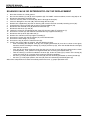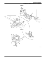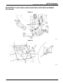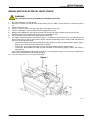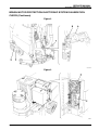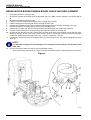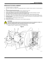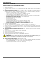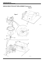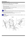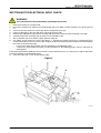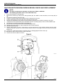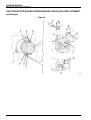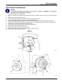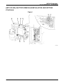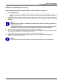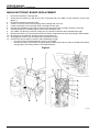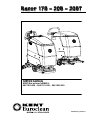
1
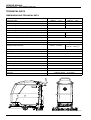
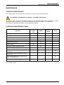
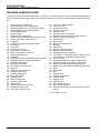
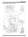
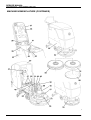
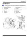
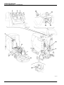
Razor 17B - 20B - 20BT
SERVICE MANUAL
KENT/Euroclean MODELS:
908 7010 020 - 908 7011 020 - 908 7025 020
08603953(2)2003-09
SERVICE MANUAL
INDEX
GENERAL INFORMATION
MACHINE LIFTING
MACHINE TRANSPORTATION
OTHER AVAILABLE MANUALS
SAFETY - ACCIDENT PREVENTION
TECHNICAL DATA
DIMENSIONS AND TECHNICAL DATA
MAINTENANCE
SCHEDULED MAINTENANCE
SCHEDULED MAINTENANCE TABLE
MACHINE NOMENCLATURE
3
3
3
3
3
4
4
5
5
5
6
DETERGENT SUPPLY SYSTEM
DETERGENT TANK AND SUPPLY SYSTEM CLEANING
DETERGENT FILTER CLEANING
SOLENOID VALVE OR DETERGENT FLOW TAP REPLACEMENT
DETERGENT FLOW CABLE AND ADJUSTING LEVER REPLACEMENT
TROUBLESHOOTING
9
9
9
10
12
14
SWEEPING SYSTEM
BRUSH MOTOR ELECTRICAL INPUT CHECK
BRUSH MOTOR PROTECTION ELECTRONIC SYSTEM CALIBRATION CHECK
BRUSH MOTOR BRUSH/CARBON BRUSH CHECK AND REPLACEMENT
BRUSH MOTOR REPLACEMENT
BRUSH REDUCTION UNIT REPLACEMENT
TROUBLESHOOTING
15
15
16
18
19
20
23
RECOVERY SYSTEM
TANK AND SUCTION GRID WITH FLOAT CLEANING
SUCTION MOTOR ELECTRICAL INPUT CHECK
SUCTION MOTOR BRUSH/CARBON BRUSH CHECK AND REPLACEMENT
SUCTION MOTOR REMOVAL
SQUEEGEE REPLACEMENT
SQUEEGEE CLEANING/CHECK AND POSSIBLE RUBBER REPLACEMENT
TROUBLESHOOTING
24
24
25
26
29
30
31
32
DRIVE SYSTEM
DRIVE MOTOR ELECTRICAL INPUT CHECK (for "20BT" version only)
DRIVE MOTOR BRUSH (OR CARBON BRUSH) CHECK AND REPLACEMENT (for "20BT" version only)
DRIVE MOTOR REPLACEMENT (for "20BT" version only)
DRIVE MOTOR BEARING GREASING (for "20BT" version only)
DRIVE WHEEL REPLACEMENT (for "20BT" version only)
DRIVE CONTROL MICRO-SWITCH ADJUSTMENT CHECK (for "20BT" version only)
TROUBLESHOOTING
OPEN CIRCUIT
THE MACHINE DOES NOT MOVE
THE MACHINE START IS SUDDEN, NOT PROGRESSIVE
33
33
34
36
38
39
40
41
41
41
41
08603953
1
SERVICE MANUAL
ELECTRICAL SYSTEM
(WET OR GEL) BATTERY REMOVAL/INSTALLATION AND SETTING
BATTERY CHARGE
MAIN ELECTRONIC BOARD REPLACEMENT
MAIN ELECTRICTRONIC BOARD SETTING CHECK (REFERENCE TABLES)
DRIVE ELECTRONIC BOARD REPLACEMENT (for "20BT" version only)
FUSE CHECK/REPLACEMENT
COMPONENT LAYOUT
WIRING DIAGRAM
2
42
42
44
46
47
49
50
51
53
08603953
SERVICE MANUAL
GENERAL INFORMATION
MACHINE LIFTING
GENERAL INFORMATION
WARNING!
Do not work under the lifted machine if it is not securely fixed.
MACHINE TRANSPORTATION
WARNING!
Before transporting the machine, ensure that:
•
All doors and carters are closed
•
The battery connection connector is disconnected
•
The machine is fastened to the means of transportation
OTHER AVAILABLE MANUALS
The following manuals are available by Kent/ Euroclean Literature Service Department:
–
Razor 17B/20B/20BT Parts List – Form Number 08812947
–
Razor 17B/20B/20BT Instructions for Use - Form Number 08812946
SAFETY - ACCIDENT PREVENTION
The following symbols indicate potentially dangerous situations. Always read carefully this information and take
the necessary precautions to protect people and objects.
DANGER!
Indicates the risk of being injured or the risk of death.
WARNING!
Indicates the risk of being injured.
CAUTION!
Indicates the risk of light injuries to people, machine or other objects.
08603953
3
SERVICE MANUAL
GENERAL INFORMATION
TECHNICAL DATA
DIMENSIONS AND TECHNICAL DATA
Razor 17B
Razor 20B-20BT
430 mm - 17 in
508 mm - 20 in
Machine length with extended handlebar
1158 mm - 45.6 in
1197 mm - 47.1 in
Machine length with lowered handlebar
1040 mm - 40.9 in
1180 mm - 46.5 in
Cleaning width
Machine height with lifted handlebar
1056 mm - 41.6 in
Machine height with lowered handlebar
943 mm - 37.1 in
Machine width without squeegee
Brush diameter
508 mm - 20.0 in
519 mm - 20.4 in
430 mm - 17 in
508 mm - 20 in
Maximum slope
2%
Clean water tank
40 litres - 10.6 gal
Dirty water tank
40 litres - 10.6 gal
Weight without batteries
260 lbs - 118 kg
278 lbs - 126 kg (*)
255 lbs - 115,5 kg
Front wheels on fixed axis
Ø 170 - 6.7 in
Pivoting rear wheels
Ø 80 - 3.1 in
Suction motor power
500 W
Brush motor power
650 W
Drive motor power (*)
130 W
Brush/Pad Speed
Acoustic pressure level
Standard batteries
Battery voltage
Battery compartment size
Vacuum
180 RPM
65 dBA
2x12V 139 Ah WET
24 V
350x350x300 mm - 13.8x13.8x11.8 in
1400 mm Water - 55 in Water
(*): For "20BT" version only
S300389
4
08603953
SERVICE MANUAL
GENERAL INFORMATION
MAINTENANCE
SCHEDULED MAINTENANCE
The machine proper and safe operation is granted by a careful and constant maintenance.
See GENERAL INFORMATION and SAFETY - ACCIDENT PREVENTION
The following table sums up the scheduled maintenance. The indicated periods can be subjected to variations
according to working conditions. These must be defined by the person in charge of the maintenance.
For maintenance operation instructions see the following paragraphs.
SCHEDULED MAINTENANCE TABLE
Operation
Squeegee cleaning
Daily, after
machine
use
!
Tank and suction grid with float cleaning
!
!
Detergent filter cleaning
Nut and screw tightening check
Yearly
!
Brush cleaning
Lead battery (WET) liquid level check
Every six
months
!
Squeegee rubber check (and replacement)
Battery charge
Weekly
!
!
! (1)
Brush electric motor carbon brushes check or
replacement
!
Suction electric motor carbon brush check or
replacement
!
Electric drive motor brush (or carbon brush)
check and replacement (*)
!
Drive shaft bearings greasing (*)
!
(1): and after the first 8 working hours
(*): for "20BT" version
08603953
5
SERVICE MANUAL
GENERAL INFORMATION
MACHINE NOMENCLATURE
In this Manual you find numbers in brackets – example: (2). These numbers refer to the components indicated in
these two nomenclature pages. Refer to these pages each time you want to find the component mentioned in the
text.
1.
2.
3.
4.
5.
6.
7.
8.
9.
10.
11.
12.
13.
14.
15.
16.
17.
18.
19.
20.
21.
22.
23.
24.
25.
26.
27.
28.
29.
30.
31.
32.
33.
34.
35.
Control panel and commands
Charged battery warning light (green)
Half-discharged battery warning light (yellow)
Discharged battery warning light (red)
Brush rotation switch
Suction switch
Detergent flow control lever
Control panel and commands mounting screws
Serial number plate / technical data
Handlebar
Handlebar inclination adjusting handles
Can holder
Tank cover
Pivoting rear wheels
Front wheels on fixed axis
Brush, or pad-holder with pad
Brush/pad-holder plate
Squeegee
Squeegee fastening handwheels to the machine
Squeegee balance adjusting handwheel
Squeegee front rubber
Squeegee rear rubber
Rear rubber fastening hook
Wing nuts
Recovery water drain hose
Detergent drain hose
Squeegee lifting lever
Brush lifting pedal
Detergent filter
Battery chager plug
Battery charger cable
Supplied key
Battery connection connector
Squeegee suction hose
Tank side fastening screw
36.
37.
38.
39.
40.
41.
42.
43.
44.
45.
46.
47.
48.
49.
50.
51.
52.
53.
54.
55.
56.
57.
58.
59.
60.
61.
62.
63.
64.
65.
66.
67.
68.
Tank cover (open position)
Tank cover seal
Compensation hole
Recovery water tank
Detergent tank
Recovery water suction hole
Suction grid with automatic closing with float
Recovery water draining hole
Suction motor
Brush motor
Electrical component box
Batteries
Battery caps
Battery assembly diagram
Electronic battery charger
Charged battery warning light
Lead (WET) or gel (GEL) battery selector switch
positioned on the electronic battery charger
Tank assembly
Brush/pad-holder plate (Razor 20B version)
Brush/pad-holder plate (Razor 17B version)
Machine forward movement adjusting knob
Machine forward movement speed adjusting knob
Brush
Disk-holder
Pad
Battery frame
Detergent tank marks
Counterweight
Detergent tap
Ignition key (*)
Drive control levers (*)
Drive speed adjuster (*)
Box with drive board and drive electrical system
fuses (*)
(*): For "20BT" version
6
08603953
SERVICE MANUAL
GENERAL INFORMATION
MACHINE NOMENCLATURE (CONTINUES)
S300390
08603953
7
SERVICE MANUAL
GENERAL INFORMATION
MACHINE NOMENCLATURE (CONTINUES)
S300391
8
08603953
SERVICE MANUAL
DETERGENT SUPPLY SYSTEM
DETERGENT TANK AND SUPPLY SYSTEM CLEANING
DETERGENT SUPPLY SYSTEM
1.
2.
3.
4.
Empty the detergent tank (40) through the hose (26).
Take the detergent flow control lever (7) in wide-open position, and then activate the machine until the
detergent inside the machine is exhausted.
If necessary, rinse the tank (40) with clean water and repeat steps 1. and 2.
Clean out the detergent filter cleaning (see the following procedure).
DETERGENT FILTER CLEANING
1.
2.
3.
4.
Close the detergent tap (A). If the machine is not equipped with the tap, it is necessary to drain the tank (40)
by means of the hose (26).
Drive the machine on a level ground.
Be sure that the switches (5) and (6) are in the "0" position (off). For "20BT" version machines, turn the key (64)
to "0".
Operating on the right lower side of the machine, remove the transparent cover (B) and the wire gauze (C),
clean and install them again on the related support (D).
Note:
When installed, the wire gauze (C) must be correctly positioned on the support (D) housing (E).
Figure 1
S300482
08603953
9
SERVICE MANUAL
DETERGENT SUPPLY SYSTEM
SOLENOID VALVE OR DETERGENT FLOW TAP REPLACEMENT
1.
2.
3.
4.
5.
6.
7.
8.
9.
10.
11.
12.
13.
14.
15.
16.
17.
Drive the machine on a level ground.
Be sure the switches (5) and (6) are in 0 position (off). For "20BT" version machines, turn the key (64) to "0".
Disconnect the battery connector (33).
If there is recovery water in the tank (39), drain it through the hose(25).
If there is detergent in the tank (40), drain it through the hose (26).
Remove the supplied key (32) from its housing and unscrew the tank assembly fastening screw (35).
Carefully lift the tank assembly (53) by means of the handlebar (10).
Disconnect the solenoid valve (B) electrical connection (A).
Disconnect the hoses (C) and (D).
Loosen the screw (E) and disengage the clamp (G) from the cable (F) of the lever (7).
Unscrew the screws (H) and move the solenoid valve-tap-support assembly (I).
Disconnect the tap lever (M) cable end (L).
Remove the solenoid valve-tap-support assembly (I).
Unscrew the screws (N) and the support (O) at the cabinet bench.
Unscrew the hose fittings (P) and (Q).
Unscrew the tap (R) from the solenoid valve (B).
Install in the reverse order of removal, with the following change:
– when reinstalling the solenoid valve (B), the stamping orientation (S) must be as shown in the figure;
moreover, before installing the fittings (P) and (Q) and the tap (R), clean the related threads and apply
LOCTITE 572 sealant.
– if the tap (R) has been replaced, check that the new part has its lever (M) facing downward as shown
(closed position), if not, position it facing downward after removing the related screw (T).
– after the cable (L) has been installed on the lever (M), fasten the cable (F) by means of the clamp (G)
and of the screw (E) in a position which meets the following conditions:
– the lever (7) in fully closed position, the lever (M) must be vertically positioned as shown (closed tap)
– the lever (7) in fully open position, the lever (M) must be horizontally positioned (open tap)
After all the components have been reinstalled, perform the lever (7) proper operation tests.
10
08603953
SERVICE MANUAL
DETERGENT SUPPLY SYSTEM
Figure 2
S300392
Figure 3
S300305
08603953
11
SERVICE MANUAL
DETERGENT SUPPLY SYSTEM
DETERGENT FLOW CABLE AND ADJUSTING LEVER REPLACEMENT
1.
2.
3.
4.
5.
6.
7.
8.
9.
10.
11.
12.
13.
14.
Drive the machine on a level ground.
Be sure the switches (5) and (6) are in 0 position (off). For "20BT" version machines, turn the key (64) to "0".
Disconnect the battery connector (33).
If there is recovery water in the tank (39), drain it through the hose (25).
If there is detergent in the tank (40), drain it through the hose (26).
Remove the supplied key (32) from its housing and unscrew the tank assembly fastening screw (35).
Carefully lift the tank assembly (53) by means of the handlebar (10).
Loosen the screw (A) and disengage the clamp (B) from the cable (C) of the lever (H).
Disconnect the tap lever (E) cable end (D).
Disconnect the cable (C) from the fixing clamps (F) along its run up to the lever (H).
Remove the handgrip (G) from the lever (H).
Unscrew the screws (I) and lightly move the panel (J).
Unscrew the screws with nut (K) and the control lever with the cable (L).
Install in the reverse order of removal, with the following change:
– after the cable (D) has been installed on the lever (E), fasten the cable (C) by means of the clamp (B)
and of the screw (A) in a position which meets the following conditions:
– the lever (H) in fully closed position, the lever (E) must be vertically positioned as shown (closed tap)
– the lever (H) in fully open position, the lever (E) must be horizontally positioned (open tap)
After all the components have been reinstalled, perform the lever (H) proper operation tests.
Figure 4
S300393
12
08603953
SERVICE MANUAL
DETERGENT SUPPLY SYSTEM
DETERGENT FLOW CABLE AND ADJUSTING LEVER REPLACEMENT
(Continues)
Figure 5
S300507
Figure 6
S300308
08603953
13
SERVICE MANUAL
DETERGENT SUPPLY SYSTEM
TROUBLESHOOTING
SMALL AMOUNT OF THE DETERGENT OR NO DETERGENT REACHES THE BRUSH
Possible cause:
1. The brush switch (5) is not in ON position or it is broken (position it to ON or repair/replace it).
2. The detergent filter is obstructed/dirty (clean it).
3. The detergent flow control lever does not control the related tap anymore (check the control lever cable, from
the lever to the tap).
4. The detergent tap is stuck closed (replace the tap).
5. The solenoid valve is broken or there is an open in the electrical connection (replace the solenoid valve/repair
the electrical connection).
6. The electronic board is broken (replace it).
7. There is debris in the detergent tank obstructing the output hole (clean the tank).
8. There is debris in the detergent hoseline obstructing the detergent flow (clean the hoseline).
THE DETERGENT REACHES THE BRUSH ALSO WHEN THE MACHINE IS OFF
Possible cause:
1. The solenoid valve is broken (replace it).
2. The electronic board is broken (replace it).
14
08603953
SERVICE MANUAL
SWEEPING SYSTEM
BRUSH MOTOR ELECTRICAL INPUT CHECK
SWEEPING SYSTEM
WARNING!
This procedure must be performed by qualified personnel only.
1.
2.
Drive the machine on a level ground.
Be sure the switches (5) and (6) are in the 0 position (off). For "20BT" version machines, turn the key (64) to
"0"
3. Remove the brush (16).
4. If there is recovery water in the tank (39), drain it through the hose (25).
5. If there is detergent in the tank (40), drain it through the hose (26).
6. Remove the supplied key (32) from its housing and unscrew the tank assembly fastening screw (35).
7. Carefully lift the tank assembly (53) by means of the handlebar (10).
8. Set an ammeter (A) on the battery supply positive cable (B).
9. For "20BT" version machines, turn the key (64) to "I". Position the brush switch (5) to I and check that the
brush motor input is 5 A max. If the input is higher, perform the following steps in order to find and eliminate
the cause of the abnormal input:
– remove from the brush rotation shaft/flange possible amounts of dirt or wrapped-round materials (ropes,
clothes, etc.), which prevent or slow down its rotation.
– if necessary, carry out the motor brush check (see the procedure on the following page).
– if necessary, disassemble the motor (see the procedure on the following pages), clean it and check its
moving parts.
If the above-mentioned procedures do not lead to a correct electrical input, it is necessary to replace the
motor (see the procedure on the following pages).
10. Carry out steps from 1. to 9. in the reverse order.
Figure 1
S300309
08603953
15
SERVICE MANUAL
SWEEPING SYSTEM
BRUSH MOTOR PROTECTION ELECTRONIC SYSTEM CALIBRATION
CHECK
Warning!
This procedure must be performed by qualified personnel only.
Note:
The check must be carried out with the batteries charged [check that the indicator light turns
on (2)].
1.
2.
3.
4.
5.
Drive the machine on a rough ground (roadbed or similar). Be careful because during the test, the machine
can leave permanent scratches on the ground.
Close the detergent flow by means of the lever (7).
Lower the brush (E) on the ground by means of the pedal (F).
Set an ammeter (A) on the battery supply cable (B).
For "20BT" version machines, turn the key (64) to "I". Activate the brush (E) by means of the switch (5) and
check that the brush motor protection system turns on with an electrical input between 30 and 45A.
The activation of the brush motor protection system is indicated by the indicator lights (3 and 4) flashing.
Note:
If the roughness of the surface is not enough to activate the motor protection system, add a
supplementary pressure on the brush plate (G) with the foot, until the indicator lights (3 e 4)
flash.
Warning:
In case of system malfunction do not persist in doing the test to avoid damaging the brush
motor or burning the safety fuse (C); proceed as indicated in the following steps.
6.
8.
9.
If the protection system activates with inputs lower than 30A, possible causes and related interventions are
the following:
– Fuse screws (C) non correctly tightened (tighten them)
– Damaged or inadequate value fuse (C) (replace it with a 50A fuse, Nilfisk original spare parts).
– Damaged fuse harness (C) (repair it).
– Damaged electronic board (replace it)
If the protection system activates with inputs higher than 50A or does not activate, possible causes and
related interventions are the following:
– Inadequate value fuse (C) (replace it with a 50A fuse, Nilfisk original spare parts).
– Damaged electronic board (replace it)
– Short circuit in the fuse harness (C) (repair it).
At the end of these operations, perform the test again (see steps from 1. to 6.).
Reset the machine by performing these operations in the reverse order.
16
08603953
7.
SERVICE MANUAL
SWEEPING SYSTEM
BRUSH MOTOR PROTECTION ELECTRONIC SYSTEM CALIBRATION
CHECK (Continues)
Figure 2
S300508
Figure 3
S300484
08603953
17
SERVICE MANUAL
SWEEPING SYSTEM
BRUSH MOTOR BRUSH/CARBON BRUSH CHECK AND REPLACEMENT
1.
2.
Drive the machine on a level ground.
Be sure the switches (5) and (6) are in the 0 position (off). For "20BT" version machines, turn the key (64) to
"0".
3. Disconnect the battery connector (33).
4. If there is recovery water in the tank (39), drain it through the hose(25).
5. If there is detergent in the tank (40), drain it through the hose (26).
6. Remove the supplied key (32) from its housing and unscrew the tank assembly fastening screw (35).
7. Carefully lift the tank assembly (53) by means of the handlebar (10).
8. Remove dust and dirt from the brush motor exterior; then disengage and remove the clamp (A).
9. For each of the four brushes, lift the retaining spring (B) and remove the brushes (C).
10. Check if the four brushes are worn. The brushes are worn when there is not sufficient contact with the motor
armature, because of their use, of the contact surface which is not integral or because the thrust spring is
broken, etc. Check the brush length: new brush = 18 mm, worn brush = 4-5 mm.
11. If necessary, remove the brushes to replace them, by unscrewing the nuts (D) and disengaging the lead-in
wires (E).
NOTE:
It is advisable to replace all four brushes at the same time, even if they are not all worn in the
same way.
12. Install in the reverse order of removal, with the following caution:
– when connecting the terminals (E), take care of their insulation from the surrounding parts of the frame.
Figure 4
S300395
18
08603953
SERVICE MANUAL
SWEEPING SYSTEM
BRUSH MOTOR REPLACEMENT
1.
2.
3.
4.
5.
6.
7.
8.
9.
10.
11.
12.
13.
Drive the machine on a level ground.
Be sure the switches (5) and (6) are in the 0 position (off). For "20BT" version machines, turn the key (64) to
"0".
Disconnect the battery connector (33).
If there is recovery water in the tank (39), drain it through the hose (25).
If there is detergent in the tank (40), drain it through the hose (26).
Remove the supplied key (32) from its housing and unscrew the tank assembly fastening screw (35).
Carefully lift the tank assembly (53) by means of the handlebar (10).
(For "20BT" version only) Loosen the wing nuts (A) and move aside the drive electronic board (B).
Remove the screws (C) and carefully remove the electric component box cover (D) making it slide upwards.
Disconnect the brush motor electrical cables (E) and (F) from the connections (G) (electromagnetic switch)
and (H) (insulator).
Cut the clamps (I) and disengage the motor cable (J).
Remove the nuts (D).
Carefully lift and remove the brush motor (L) with its pinion and bearing.
CAUTION!
To prevent part (M) and part (N) from separating during the motor disassembly/reassembly, it is
advisable to apply adhesive tape temporarily to keep the two parts together.
14. Install in the reverse order of removal, with the following change:
– If applied at step 13, remember to remove the adhesive tape.
Figure 5
S300311
08603953
19
SERVICE MANUAL
SWEEPING SYSTEM
BRUSH REDUCTION UNIT REPLACEMENT
1.
2.
3.
4.
5.
6.
7.
8.
9.
10.
11.
12.
13.
14.
Remove the brush (16).
Be sure the switches (5) and (6) are in the 0 position (off). For "20BT" version machines, turn the key (64) to
"0".
Disconnect the battery connector (33).
Lift the machine by means of a lifting system, if available, in order to work under the brush-holder (54/55); if
the lifting system is not available, lay down the machine on one side and perform the following procedure:
– Remove the suction squeegee (see the related paragraph).
– If there is recovery water in the tank (39), drain it through the hose (25).
– If there is detergent in the tank (40), drain it through the hose (26).
– Remove the supplied key (32) from its housing and unscrew the tank assembly fastening screw (35).
– Carefully lift the tank assembly (53) by means of the handlebar (10).
– Disconnect the battery (47) negative cable (-).
– Disconnect the other cables of the batteries.
– Remove the batteries (47).
– Remove the battery frame (61).
– Perform the following steps from 5. to 8. before laying down the machine.
– Carefully lower the tank assembly (53) by means of the handlebar (10).
– Lay down the machine on one side and set it down carefully on proper guards (A).
– Open the tank assembly (C) completely by means of the handlebar (B).
Disconnect the detergent hose (D).
(For "20BT" version only) Loosen the wing nuts (E) and move aside the drive electric box (F).
Remove the screws (G) and carefully remove the electric component box cover (H) making it slide upwards.
Disconnect the brush motor electrical cables (I) and (J) from the connections (K) (electromagnetic switch)
and (L) (insulator).
Cut the clamps (M) and disengage the motor cable (N).
Operating on the brush installation area, remove the screw (O), remove the flange assembly (P) and recover
the key (Q).
Remove the screws (R) and the reduction unit with the motor (S).
Remove the detergent hose (T).
Remove the motor mounting nuts (U) to the reduction unit.
Carefully lift and remove the brush motor (V) with its pinion and bearing.
CAUTION!
To prevent part (T) and part (U) from separating during the motor disassembly/reassembly, it is
advisable to apply adhesive tape temporarily to keep the two parts together.
15. Recover the reduction unit with oil (Y).
16. Install in the reverse order of removal, with the following change:
– Before installing the new reduction unit, fill in with oil of the type and quantity indicated by the reduction
unit data plate (SAE W 80 - 90 oil). The oil in the tank must cover the gear (Z).
– If applied at step 14, remember to remove the adhesive tape.
20
08603953
SERVICE MANUAL
SWEEPING SYSTEM
Figure 6
S300486
08603953
21
SERVICE MANUAL
SWEEPING SYSTEM
BRUSH REDUCTION UNIT REPLACEMENT (Continues)
Figure 8
Figure 7
S300314
S300396
22
08603953
SERVICE MANUAL
SWEEPING SYSTEM
TROUBLESHOOTING
OPEN CIRCUIT
The brush motor fuse determines the open circuit. This system allows to prevent the brush motor circuits from
being damaged in case of short circuit.
If there is an open in the electrical circuit, the possible causes are the following:
1. Short circuit: check all cable and connection insulation integrity.
2. Engine locked: check that debris or other objects do not prevent the engine rotation.
THE BRUSH DOES NOT ROTATE
Possible cause:
1. The battery voltage is too low (check the battery charge indicator on the control panel).
2. The electrical motor brushes are worn (replace the electrical motor brushes).
3. Malfunction in the electrical motor (repair or replace the electrical motor).
4. Brush motor burned fuse (remove the cause and replace the fuse).
5. The brush ON/OFF switch (5) is broken (replace it).
6. Malfunction in the reduction unit (repair or replace it).
7. The wiring harness is damaged (repair it).
8. The electromagnetic switch is damaged (replace it).
BRUSH MOTOR ELECTRONIC PROTECTION INTERVENTION (See Use and Maintenance Manual)
Possible causes:
1. Insufficient water on the floor (increase water amount).
2. The floor is too rough for the brush you are using.
3. There are bulky waste materials or cords around the brush or between the brush and its flange (disassemble
the brush and remove the waste materials or cords).
4. The brush motor electrical input is too high (check the electrical input).
5. The brush motor protection system does not work properly (see the specified paragraph for the system
calibration).
08603953
23
SERVICE MANUAL
RECOVERY SYSTEM
TANK AND SUCTION GRID WITH FLOAT CLEANING
RECOVERY SYSTEM
1.
2.
3.
4.
5.
Push the machine to the appointed disposal area.
Be sure the switches (5) and (6) are in the 0 position (off). For "20BT" version machines, turn the key (64) to
"0".
Lift the cover (A), clean and wash with clean water the cover (A), the tanks (B) and (C) and the screen (D) of
the suction automatic closing.
Drain the water from the tanks by means of the hoses (25 and 26).
If necessary, release the retainers (E) and open the screen (D); recover the float (F), clean all the
components and then reinstall them.
Check the integrity of the tank cover gasket (G).
Remark:
The gasket (G) creates vacuum in the tank that is necessary for the suction of recovery water.
If necessary replace the gasket (G) after removing it from its housing (H). When assembling the new gasket, install
its joint (I) in the (central) area as shown in the figure.
6. Be sure that the gasket (G) bearing surface (J) is integral and adequate for the gasket.
7. Be sure that the compensation hole (K) is not obstructed.
Remark:
The hole (K), allowing to compensate the air in the cover interspaces, contributes to create
vacuum in the tank.
8.
Close the cover (A).
Figure 1
S300397
24
08603953
SERVICE MANUAL
RECOVERY SYSTEM
SUCTION MOTOR ELECTRICAL INPUT CHECK
WARNING!
This procedure must be performed by qualified personnel only.
1.
2.
Drive the machine on a level ground.
Be sure the switches (5) and (6) are in the 0 position (off). For "20BT" version machines, turn the key (64) to
"0"
3. If there is recovery water in the tank (39), drain it through the hose (25).
4. If there is detergent in the tank (40), drain it through the hose (26).
5. Remove the supplied key (32) from its housing and unscrew the tank assembly fastening screw (35).
6. Carefully lift the tank assembly (53) by means of the handlebar (10).
7. Set an ammeter (A) on the battery supply positive cable (B).
8. For "20BT" version machines, turn the key (64) to "I". Position the suction switch (6) to I and check that the
suction motor input is 22 A max. If the input is higher, perform the following steps in order to find and eliminate
the cause of the abnormal input:
– carry out the motor brush check (see the procedure on the following page).
– if necessary, disassemble the motor (see the procedure on the following pages), clean it and check its
moving parts.
If the above-mentioned procedures do not lead to a correct electrical input, it is necessary to replace the motor
(see the procedure on the following pages).
9. Carry out steps from 1. to 8. in the reverse order.
Figure 2
S300316
08603953
25
SERVICE MANUAL
RECOVERY SYSTEM
SUCTION MOTOR BRUSH/CARBON BRUSH CHECK AND REPLACEMENT
NOTE:
The motor installed on the machine can either be a FISE or a AMETEK.
The following procedure refers to the FISE motor only.
1.
2.
Drive the machine on a level ground.
Be sure the switches (5) and (6) are in the 0 position (off). For "20BT" version machines, turn the key (64) to
"0".
3. Disconnect the battery connector (33).
4. If there is recovery water in the tank (39), drain it through the hose (25).
5. If there is detergent in the tank (40), drain it through the hose (26).
6. Remove the supplied key (32) from its housing and unscrew the tank assembly fastening screw (35).
7. To operate on the suction motor (44) carefully lift the tank assembly (53) by means of the handlebar (10).
8. Disconnect the suction motor electrical connector (A).
9. Unscrew the screws (B) and remove the deadening guard (C).
10. Remove the cover (D) (that is pressurized) from the suction motor (E).
11. Remove the brushes (F).
12. Check if the brushes are worn. The brushes are worn when there is not sufficient contact with the motor
armature, because of their use, of the contact surface which is not integral or because the thrust spring is
broken, etc.
13. If necessary, remove the brushes to replace them, by disengaging the lead-in wires (G).
It is advisable to replace all the brushes at the same time.
14. Install in the reverse order of removal.
Figure 3
S300317
Figure 4
S300318
26
08603953
SERVICE MANUAL
RECOVERY SYSTEM
SUCTION MOTOR BRUSH/CARBON BRUSH CHECK AND REPLACEMENT
NOTE:
The motor installed on the machine can either be a FISE or a AMETEK.
The following procedure refers to the AMETEK motor only.
1.
2.
3.
4.
5.
6.
7.
8.
9.
10.
11.
12.
13.
14.
15.
1. Drive the machine on a level ground.
Be sure that the switches (5) and (6) are in the "0" position (off). For "20BT" version machines, turn the key
(64) to "0".
Disconnect the battery connector (33).
If there is recovery water in the tank (39), drain it through the hose (25).
If there is detergent in the tank (40), drain it through the hose (26).
Remove the supplied key (32) from its housing and remove the tank assembly fastening screw (35).
To operate on the suction motor (44) carefully lift the tank assembly (53) by means of the handlebar (10).
Disconnect the suction motor electrical connector (A).
Remove the screws (B) and remove the deadening guard (C).
Disengage the retainers (D) and (E) and then remove the cover (F) from the suction motor (G).
Loosen the screws (H) and remove the retainers (I).
Disconnect the electrical connections (J) and remove the brushes (K).
Check if the brushes are worn. The brushes are worn when there is not sufficient contact with the motor
armature, because of their use, of the contact surface which is not integral or because the thrust spring is
broken, etc.
If necessary, replace the brushes. It is advisable to replace all the brushes at the same time.
Install in the reverse order of removal.
Figure 5
S300317
08603953
27
SERVICE MANUAL
RECOVERY SYSTEM
SUCTION MOTOR BRUSH/CARBON BRUSH CHECK AND REPLACEMENT
(continues)
Figure 6
S300487
28
08603953
SERVICE MANUAL
RECOVERY SYSTEM
SUCTION MOTOR REMOVAL
NOTE:
The motor installed on the machine can either be a FISE or a AMETEK. The following
procedure refers to both types of motors.
1.
2.
3.
4.
5.
6.
7.
8.
9.
10.
11.
12.
13.
Drive the machine on a level ground.
Be sure the switches (5) and (6) are in the 0 position (off). For "20BT" version machines, turn the key (64) to
"0"
Disconnect the battery connector (33).
If there is recovery water in the tank (39), drain it through the hose (25).
If there is detergent in the tank (40), drain it through the hose (26).
Remove the supplied key (32) from its housing and unscrew the tank assembly fastening screw (35).
To operate on the suction motor (44) carefully lift the tank assembly (53) by means of the handlebar (10).
Disconnect the suction motor electrical connector (A).
Unscrew the screws (B) and remove the deadening guard (C).
Unscrew the motor fastening screws (D).
Remove the suction motor (E) and the joint (F).
Recover the gasket (G) that is between the motor and the structure.
Install in the reverse order of removal.
Figure 7
S300317
Figure 8
S300319
08603953
29
SERVICE MANUAL
RECOVERY SYSTEM
SQUEEGEE REPLACEMENT
1.
2.
3.
4.
5.
6.
7.
Drive the machine on a level ground.
Be sure the switches (5) and (6) are in the 0 position (off). For “20BT” version machines, turn the key (64) to
"0".
Lower the squeegee (18) by means of the lever (27).
Disconnect the suction hose (34) from the squeegee.
Loosen the handwheels (19) and remove the squeegee (18).
Install in the reverse order of removal.
If necessary, adjust the balancing handwheel (20) of the squeegee.
30
08603953
SERVICE MANUAL
RECOVERY SYSTEM
SQUEEGEE CLEANING/CHECK AND POSSIBLE RUBBER REPLACEMENT
CAUTION!
It is advisable to use protective gloves when cleaning the squeegee because there can be cutting
debris.
Squeegee cleaning
1.
2.
3.
Remove the squeegee as described on the previous page.
Wash and clean the squeegee; in particular, clean the compartments (A) and the hole (B) from dirt and
debris. Check that the front rubber (C) and the rear rubber (D) are integral and free from cuts and lacerations;
otherwise replace them (see following steps).
Install in the reverse order of removal.
Squeegee rubber check
4.
5.
6.
Clean the squeegee (as described in the previous steps).
Check that the front rubber edge (E) and the rear rubber edge (F) lay down on the same level, along their
length; otherwise adjust their height as described below:
– disengage the retainer (G) and loosen the wing nuts (H) to adjust the rear rubber (D); then tighten the
wing nuts and engage the retainer.
– loosen the nuts (I) to adjust the front rubber (C); then tighten the nuts.
Check that the front rubber (C) and the rear rubber (D) are integral and free from cuts and lacerations;
otherwise replace them as described below.
Check that the front corner (J) of the rear rubber is not worn; otherwise, overturn the rubber to replace the
worn corner with an integral one. If the other corners are worn too, replace the rubber; proceed as described
below.
Squeegee rubber replacement (or overturning)
7.
To replace (or overturn) the rear rubber (D) disengage the retainer (G), unscrew the wing nuts (H) and the
retaining strip (K). Install in the reverse order of removal.
To replace the front rubber (C) unscrew the nuts (I) and remove the retaining strip (L). Install in the reverse
order of removal.
After the rubber replacement (or overturning), adjust their height as described at step 5.
8. Reinstall the squeegee as described on the previous page.
9. If necessary, adjust the balancing handwheel (20) of the squeegee.
Figure 9
S300320
08603953
31
SERVICE MANUAL
RECOVERY SYSTEM
TROUBLESHOOTING
OPEN CIRCUIT
The suction motor fuse determines the open circuit. This system allows to prevent the suction motor and its circuits
from being damaged in case of short circuit.
If there is an open in the electrical circuit, the possible causes are the following:
1. The motor is damaged (check the motor brushes/motor electrical input).
2. Damaged cable (check all cable and connection insulation integrity).
DIRTY WATER SUCTION IS INSUFFICIENT OR THERE IS NO SUCTION
Possible cause:
1. The float automatic closing (42) is activated because the water recovery tank (39) is too full (empty the water
recovery tank).
2. Dirty float shield (42) (clean it).
3. The tank cover (36) is not correctly positioned (place it correctly).
4. The tank cover gasket is not efficient or the compensating hole (38) is obstructed (remove the causes).
5. The squeegee or the suction hose is obstructed or damaged (clean or repair/replace them)
6. The electrical motor brushes are worn (replace the electrical motor brushes).
7. Malfunction in the electrical suction motor (repair or replace the electrical motor).
8. Burned fuse (remove the cause and replace the fuse)
9. The suction ON/OFF switch (6) is broken (replace it).
10. The wiring harness is damaged (repair it).
11. The suction motor electromagnetic switch is broken (replace it).
THE SQUEEGEE LEAVES LINING OR DOES NOT COLLECT WATER
Possible cause:
1. There is debris under the squeegee lip (remove them).
2. The squeegee rubber lips are torn or worn (replace them)
3. The squeegee is unbalanced [balance it by means of the handwheel (20)].
32
08603953
SERVICE MANUAL
DRIVE SYSTEM
DRIVE MOTOR ELECTRICAL INPUT CHECK (for "20BT" version only)
DRIVE SYSTEM
Warning:
This procedure must be performed by qualified personnel only.
1.
2.
3.
4.
5.
6.
7.
8.
9.
10.
11.
Drive the machine on a level ground.
Turn the key (64) to "0".
If there is recovery water in the tank (39), drain it through the hose (25).
If there is detergent in the tank (40), drain it through the hose (26).
Remove the supplied key (32) from its housing and remove the tank assembly fastening screw (35).
Carefully lift the tank assembly (53) by means of the handlebar (10).
Loosen the screws (A) and remove the drive electronic board cover (B).
Set an ammeter (C) on the drive motor cable (D).
Turn the ignition key (64) to "I" position.
Set the drive speed adjuster (66) at the maximum speed.
Lift the drive wheels (E) from the ground and keeping them well lifted, activate the drive control levers (65)
and check that the drive motor input is max 2,5A at 24V.
Release the levers (65) and when the wheels (E) stop, lower them on the ground; turn the key (64) to "0".
If the electrical input is higher, perform the following operations to detect and correct the causes:
–
Remove from the drive wheels shaft all the possible amounts of dirt or wrapped-round materials (ropes,
clothes, etc.), which prevent or slow down its rotation.
–
If necessary, carry out the motor brush check (see the procedure on the following page).
–
If necessary, disassemble the motor (see the procedure on the following pages), clean it and check its
moving parts.
If the above-mentioned procedures do not lead to a correct electrical input, it is necessary to replace the motor
(see the procedure on the following pages).
12. Carry out steps from 1. to 10. in the reverse order.
Figure 1
S300488
08603953
33
SERVICE MANUAL
DRIVE SYSTEM
DRIVE MOTOR BRUSH (OR CARBON BRUSH) CHECK AND REPLACEMENT
(for "20BT" version only)
1.
2.
3.
4.
5.
6.
7.
8.
9.
10.
11.
12.
13.
Remove the brush (16).
Turn the key (64) to "0".
Disconnect the battery connector (33).
Lay down the machine on one side, operating as described below:
– Remove the suction cap (see the related paragraph).
– If there is recovery water in the tank (39), drain it through the hose (25).
– If there is detergent in the tank (40), drain it through the hose (26).
– Remove the supplied key (32) from its housing and remove the tank assembly fastening screw (35).
– Carefully lift the tank assembly (53) by means of the handlebar (10).
– Disconnect the battery (47) negative cable (-).
– Disconnect the other cables of the batteries.
– Remove the batteries (47).
– Remove the battery frame (61).
– Carefully lower the tank assembly (53) by means of the handlebar (10).
– Lay down the machine on one side and set it down carefully on proper guards (A).
– Open the tank assembly (C) completely by means of the handlebar (B).
Remove the upper drive motor fastening screws (D).
Remove the wheel axle screws (E) and loosen the screws (O).
Turn the drive motor (F) slightly on the wheel axle.
Clean the exterior part of the drive motor (F) from dirty and dust, then mark the reciprocal position (G)
between the cover (H) and the motor body (I).
Carefully remove the screws (L) and the cover (H).
Check if the two brushes (M) are worn. The brushes are worn when there is not sufficient contact with the
motor armature, because of their use, of the contact surface which is not integral or because the thrust spring
is broken, etc.
If necessary, remove the brushes to replace them, by disengaging the lead-in wires (N).
It is advisable to replace all the brushes at the same time.
Install in the reverse order of removal.
Figure 2
S300489
34
08603953
SERVICE MANUAL
DRIVE SYSTEM
DRIVE MOTOR BRUSH (OR CARBON BRUSH) CHECK AND REPLACEMENT
(for "20BT" version only) (Continues)
Figure 3
S300490
08603953
35
SERVICE MANUAL
DRIVE SYSTEM
DRIVE MOTOR REPLACEMENT (for "20BT" version only)
1.
2.
3.
4.
5.
6.
7.
Remove the brush (16).
Turn the key (64) to "0".
Disconnect the battery connector (33).
Loosen the screws (A) and remove the drive electronic board cover (B).
Disconnect the electrical connections (C) and (D) from the drive motor.
Cut the clamp (E) and remove the drive motor harness (F).
Lay down the machine on one side, operating as described below:
– Remove the suction cap (see the related paragraph).
– If there is recovery water in the tank (39), drain it through the hose (25).
– If there is detergent in the tank (40), drain it through the hose (26).
– Remove the supplied key (32) from its housing and remove the tank assembly fastening screw (35).
– Carefully lift the tank assembly (53) by means of the handlebar (10).
– Disconnect the battery (47) negative cable (-).
– Disconnect the other cables of the batteries.
– Remove the batteries (47).
– Remove the battery frame (61).
– Carefully lower the tank assembly (53) by means of the handlebar (10).
– Lay down the machine on one side and set it down carefully on proper guards (G).
– Open the tank assembly (I) completely by means of the handlebar (H).
8. Remove the upper drive motor fastening screws (J).
9. Remove the wheel axle screws (K) and loosen the screws (O).
10. Turn the drive motor (L) slightly on the wheel axle.
11. Remove the screws (M) and carefully remove the drive motor by disengaging the reduction unit (N)
connecting worm screw.
12. Install in the reverse order of removal.
Figure 4
S000491
36
08603953
SERVICE MANUAL
DRIVE SYSTEM
DRIVE MOTOR REPLACEMENT (for "20BT" version only) (continues)
Figure 5
S300492
Figure 6
S300493
08603953
37
SERVICE MANUAL
DRIVE SYSTEM
DRIVE MOTOR BEARING GREASING (for "20BT" version only)
1.
2.
3.
4.
Turn the key (64) to "0".
Remove the protection caps (A) from the lubricators (B) of each drive wheel (C).
By means of a lubricator apply AIVAVIA GREASE 3 or a "Li soap" mineral grease.
Clean the lubricators (B) and install the protection caps (A) again.
Figure 7
S300494
38
08603953
SERVICE MANUAL
DRIVE SYSTEM
DRIVE WHEEL REPLACEMENT (for "20BT" version only)
1.
2.
3.
4.
5.
6.
7.
Turn the key (64) to "0".
Slightly lift the machine drive wheels.
Remove the screws (A).
Remove the wheels (B)
Install the new wheels (B), consider that the right wheel is different from the left wheel; the right wheel has a
blue label (C).
Apply a strip (D) of Loctite 243 at half of the length of the screws (A), then loosen the screws (A) at 50 Nm
tightening torque.
Lower the machine drive wheels.
Figure 8
D
A
B
C
B
A
S300495
08603953
39
SERVICE MANUAL
DRIVE SYSTEM
DRIVE CONTROL MICRO-SWITCH ADJUSTMENT CHECK (for "20BT"
version only)
Note:
Perform this check when there is not a machine progressive start at the activation of the drive
control levers (65), but there is a sudden start.
1.
2.
3.
4.
5.
Turn the ignition key (A) to "0" position.
Remove the half bearing fastening screws (B).
Slightly move the half bearings (C) and (D).
Disconnect the electrical connections from the micro-switches (E) and recover the half bearings (C) and (D).
Activate the drive control levers (G) forward and backward and check that the micro-switch (E) related to
black cam, between the two cams (I), (connected to white cables) is activated first.
Check both micro-switches operation (E) by means of a tester.
If the test is negative, it is necessary to replace the cams and micro-switches assembly.
6. Carry out steps from 2. to 4. in the reverse order.
Figure 9
S300496
40
08603953
SERVICE MANUAL
DRIVE SYSTEM
TROUBLESHOOTING
OPEN CIRCUIT
The drive motor fuse determines the open circuit. This system allows to prevent the drive motor circuits from being
damaged under overload conditions.
If there is an open in the electrical circuit, the possible causes are the following.
Drive motor; the fuse burns and opens the electrical circuit. Possible causes:
1.
2.
3.
There are debris or cords under the machine or around the drive wheels (remove debris or cords).
The motor is damaged (check the motor brushes/motor electrical input).
The slope is excessive (do not use the drive system to pass over slopes higher than 2%)
THE MACHINE DOES NOT MOVE
Possible causes:
1.
2.
3.
4.
5.
The battery voltage is too low (charge the battery).
The electronic board fuse is burned (replace it).
The drive electronic board has a malfunction (replace it).
The drive control lever micro-switches are broken (replace them).
The harness is damaged (repair it).
THE MACHINE START IS SUDDEN, NOT PROGRESSIVE
Possible causes:
The drive control micro-switches with cams assembly does not work (replace it).
08603953
41
SERVICE MANUAL
ELECTRICAL SYSTEM
(WET OR GEL) BATTERY REMOVAL/INSTALLATION AND SETTING
ELECTRICAL SYSTEM
Removal
1.
2.
Drive the machine on a level ground.
Be sure the switches (5) and (6) are in the 0 position (off). For "20BT" version machines, turn the key (64) to
"0"
3. Disconnect the battery connector (33).
4. If there is recovery water in the tank (39), drain it through the hose (25).
5. If there is detergent in the tank (40), drain it through the hose (26).
6. Remove the supplied key (32) from its housing and unscrew the tank assembly fastening screw (35).
7. Carefully lift the tank assembly (53) by means of the handlebar (10).
8. Disconnect the battery cables (47).
9. Remove the batteries (47).
10. If necessary, remove the battery frame (61).
Setting (WET or GEL)
11. If the type of battery chosen to be installed is different from the removed one (not Wet but Gel, or vice versa),
before installing the batteries on the machine and connect the new batteries, the machine electronic board
and battery charger setting must be performed, proceeding in the following way.
Machine setting
12.
13.
14.
15.
Ensure that the battery connector (33) is completely disconnected.
(For "20BT" version only) Loosen the wing nuts (A) and move aside the drive electronic board (B).
Remove the screws (C) and carefully remove the electric component box cover (D) making it slide upwards.
On the electronic board place the micro-switch (F) to the Wet (Pb) or Gel position according to the type of
battery that is to be installed.
WARNING:
Do not move the adjacent switch (E), which is related to the battery charger.
16. Reinstall the electric component box cover (D) and install the screws (C).
17. Reinstall the drive electric board (B) and the wing nuts (A).
Battery charger setting
18. Place the selector (G) to the Wet (Pb) or Gel position according to the type of battery that is to be installed.
Battery installation and charge
19. Install the batteries on the machine according to the diagram (H) and carry out steps 8., 9. and 10. in the
reverse order.
20. If necessary, charge the batteries (see the procedure in the Use and Maintenance Manual).
21. Carry out steps from 1. to 7. in the reverse order.
42
08603953
SERVICE MANUAL
ELECTRICAL SYSTEM
(WET OR GEL) BATTERY REMOVAL/INSTALLATION AND SETTING
(Continues)
Figure 1
S300497
08603953
43
SERVICE MANUAL
ELECTRICAL SYSTEM
BATTERY CHARGE
CAUTION!
Charge the batteries when the warning light (3 or 4) turns on and at the end of every cleaning.
Keeping the batteries charged make their life last longer.
CAUTION!
When the batteries are discharged, recharge them as soon as possible, as that condition
makes their life shorter.
Check for battery charge at least once a week.
WARNING!
Battery charging produces explosive hydrogen gas. Charge the batteries only in
well-ventilated areas and far from naked flames.
Do not smoke during battery charging.
Keep the tank assembly open while recharging the battery.
WARNING!
Pay attention during battery recharging because there can be battery liquid leakages. The
battery liquid is corrosive. If it comes in contact with the skin or eyes, rinse thoroughly with
water and consult a physician.
1.
2.
3.
4.
5.
44
Drive the machine on a level ground.
Remove the supplied key (32) from its housing and remove the tank assembly fastening screw (35).
Carefully lift the tank assembly (53) by means of the maneuver handle (10).
For lead batteries only:
– Check for correct level of electrolyte inside the battery; if necessary, top up through the caps (48).
– Leave the caps (48) open for next recharging.
– Clean (if necessary) the upper surface of the battery.
Proceed with recharging the battery according to one of the following ways, depending on the presence of
the electronic battery charger (50).
08603953
SERVICE MANUAL
ELECTRICAL SYSTEM
BATTERY CHARGE (Continues)
Battery charging with (optional) electronic battery charger installed on the machine
1.
2.
For lead batteries only:
– Check for correct level of electrolyte inside the battery; if necessary, top up through the caps (48).
– When the correct level is reached, close the caps (48) and clean (if necessary) the upper surface of the
battery.
Connect the battery charger electrical connector (30) to the electrical system (the system voltage and
frequency must be compatible with the battery charger values: see the battery charger OPERATING
MANUAL).
Note:
When the battery charger is connected to the electrical system, all machine functions are
automatically cut off.
When the red warning light (4) on the control panel turns on (only with optional battery charger
installed on the machine), it shows that the battery charger is charging the batteries.
3.
4.
5.
6.
7.
When the red warning light (4) turns off, the battery charging is completed.
Once the battery charging is completed, disconnect the battery charger electric connector (30) from the
electric system and hook it to its housing on the machine.
Carefully lower the tank assembly (53) by means of the maneuver handle (10).
Remove the supplied key (32) from its housing and install the tank assembly fastening screw (35).
Now the machine is ready to be used.
Note:
For further information about the battery charger operation (50), see the related Manual.
08603953
45
SERVICE MANUAL
ELECTRICAL SYSTEM
MAIN ELECTRONIC BOARD REPLACEMENT
1.
2.
Drive the machine on a level ground.
Check that the switches (5) and (6) are in the "0" position (off). For "20BT" version machines, turn the key
(64) to "I".
3. Disconnect the battery connector (33).
4. If there is recovery water in the tank (39), drain it through the hose (25).
5. If there is detergent in the tank (40), drain it through the hose (26).
6. Remove the supplied key (32) from its housing and remove the tank assembly fastening screw (35).
7. Carefully lift the tank assembly (53) by means of the handlebar (10).
8. (For "20BT" version only) Loosen the wing nuts (A) and move aside the drive electronic board (B).
9. Remove the screws (C) and carefully remove the electric component box cover (D) making it slide upwards.
10. Disconnect all the electronic board (F) electric connections (E).
11. Disengage the retainers (G) and remove the electronic board (F).
12. Install in the reverse order of removal, with the following change:
– Be sure that the board/solenoid valve fuse (H) is installed.
– Position the switch (J) related to the type of battery (Wet or Gel) and the switch (I) related to the battery
charger (50) in the same position as the replaced board.
Figure 2
S300498
46
08603953
SERVICE MANUAL
ELECTRICAL SYSTEM
MAIN ELECTRICTRONIC BOARD SETTING CHECK (REFERENCE TABLES)
a) Pb/gel micro-selector
1
Pb
Lead/acid batteries
0
Gel
Gel batteries
V tol.: ± 0,1V
Pb
Gel
Green -> yellow
20.0
21.4
Yellow -> red (flashing)
18.6
19.8
b) Battery charger micro-selector
0
Ch
For machines with SPE battery charger on board
WARNING:
The SPE battery charger must be connected to the battery + cable and to the CH faston of the
electronic board to power the electronic board with +24V: if the battery charger is to be removed
from the machine for service, set the selector to "NO Ch" to work with the machine when the
battery charger is not installed.
c) Voltage references:
Working conditions:
A: All turned off
B: Brush on, vacuum motor off
C: Brush off, vacuum motor on
Upper 8-Way Connector MODU1 Type
PIN
Description
Working conditions
A
B
C
1
CS
Switches
24V
24V
24V
2
BS
Brush switch
Indef.
24V
Indef.
3
VS
Aspirator switch
Indef.
Indef.
24V
4
LR
Red LED (<=> EB2 PIN 2)
Indef.
depending on
battery condition
5
LG
Yellow LED (<=> EB2 PIN 3)
Indef.
depending on
battery condition
6
LV
Green LED (<=> EB2 PIN 4)
Indef.
depending on
battery condition
7
LC
LED common (<=> EB2 PIN 1)
24V
24V
24V
8
V-
Aux 0V
0V
0V
0V
08603953
47
SERVICE MANUAL
ELECTRICAL SYSTEM
2-Way Connector MODU1 Type
PIN
Description
Working conditions
A
B
C
1
W+
Solenoid valve +
24V
24V
24V
2
W-
Solenoid valve -
Indef.
0V
Indef.
Lower 8-Way Connector MODU1 Type
PIN
Description
Working conditions
A
B
C
1
CT
Electromagnetic switches
24V
24V
24V
2
BT
Brush electromagnetic switch
Indef.
0V
Indef.
3
VT
Aspirator electromagnetic switch
Indef.
Indef.
0V
4
S-
- shunt
0V
0V
0V
5
S+
+ shunt
0V
<40mV
0V
6
V-
Power -
0V
0V
0V
7
V+
Power +
24V
24V
24V
8
BL
Battery charger output (for red LED)
Indef. (*)
Indef.
Indef.
(*) depends on the connection of the battery charger to the mains: only the battery charger connected to the mains
(ON) => 0V (high resistance) for the red LED cathode.
Fastons
PIN
Description
Working conditions
A
B
C
1
6,3
SPE battery charger power supply
24V (*)
24V (*)
24V (*)
2
4,8
SPE battery charger red LED power supply
Indef. (**)
Indef.
Indef.
(*) depends on the connection of the battery charger to the mains: only with the battery charger connected to the
mains (OFF) => 24V
(**) depends on the connection of the battery charger to the mains: only the battery charger connected to the
mains (ON) => 0V (high resistance) for the red LED cathode.
48
08603953
SERVICE MANUAL
ELECTRICAL SYSTEM
DRIVE ELECTRONIC BOARD REPLACEMENT (for "20BT" version only)
1.
2.
3.
4.
5.
6.
7.
8.
9.
10.
11.
Drive the machine on a level ground.
Turn the key (64) to "0".
Disconnect the battery connector (33).
If there is recovery water in the tank (39), drain it through the hose (25).
If there is detergent in the tank (40), drain it through the hose (26).
Remove the supplied key (32) from its housing and remove the tank assembly fastening screw (35).
Carefully lift the tank assembly (53) by means of the handlebar (10).
Loosen the screws (A) and remove the cover (B).
Disconnect all the drive electronic board (D) electric connections (C).
Remove the nuts (E) and remove the drive electronic board (D).
Install in the reverse order of removal, with the following change:
– Be sure that the electronic board protection fuse (F) is installed.
Figure 3
S300500
08603953
49
SERVICE MANUAL
ELECTRICAL SYSTEM
FUSE CHECK/REPLACEMENT
1.
2.
3.
4.
5.
6.
Disconnect the battery connector (33).
Drain the water from the tanks (39 and 40) by means of the hoses (25 and 26).
Remove the supplied key (32) from its housing and remove the tank assembly fastening screw (35).
Carefully lift the tank assembly (53) by means of the handle (10).
(for "20BT" version only) Loosen the screws (A) and remove the cover (B).
(for "20BT" version only) Check/replace the fuses:
– Drive fuse (30A) (C)
– Electronic board protection fuse (2A) (D)
7. (For "20BT" version only) Loosen the wing nuts (E) and move aside the drive electronic board support (F).
8. Remove the screws (G) and carefully remove the electric component box cover (H) making it slide upwards.
9. Check/replace the fuses:
– Brush safety fuse (50A) (I)
– Vacuum motor fuse (40A) (J)
– Solenoid valve fuse (5A) (K)
10. Install in the reverse order of removal.
NOTE:
Be careful when assembling the fuses, especially those for the brush safety; if not assembled
correctly, the electronic system for the protection of the brush motor overload can be affected.
After fuse replacement, perform the brush motor overload protection electronic system
operation check (see the related paragraph).
Figure 4
S300501
50
08603953
SERVICE MANUAL
ELECTRICAL SYSTEM
COMPONENT LAYOUT
Note:
The symbol in brackets (..) after the name of the component refers to the wiring diagram (see
the following pages).
1.
2.
3.
4.
5.
6.
7.
8.
9.
10.
11.
12.
13.
14.
15.
16.
Charged battery warning light (green)
Half-discharged battery warning light (yellow)
Discharged battery warning light (red)
Brush motor switch (SW1)
Suction motor switch (SW2)
Suction motor (M1)
Brush motor (M2)
Battery connection connector (C1)
Batteries
Battery charger (CH1)
Brush fuse (F1)
Aspirator fuse (F2)
Board/solenoid valve fuse (F3)
Electromagnetic switch
Electromagnetic switch
Main electronic board (EB1)
17.
18.
19.
20.
21.
22.
23.
24.
25.
26.
27.
28.
Lead (WET) or gel (GEL) battery selector switch (positioned on
the electronic battery charger)
Battery charger presence/absence selector (positioned on the
electronic board)
Lead (WET) or gel (GEL) battery selector switch (positioned on
the electronic board)
Detergent supply solenoid valve (EV1)
(*) Drive electronic board (EB3)
(*) Drive fuse (F4)
(*) Key switch (K1)
(*) Drive motor (M3)
(*) Drive control levers
(*) Drive speed adjuster
(*) Drive electronic board fuse
(*) Drive control lever micro-switches
(*): for "20BT" version
S300502
08603953
51
SERVICE MANUAL
ELECTRICAL SYSTEM
S300509
52
08603953
SERVICE MANUAL
ELECTRICAL SYSTEM
WIRING DIAGRAM
Kent Euroclean Razor 17B / 20B
EB2
SW2
SW1
BK
Legend
CH1
C1
EB1
EB2
ES1
ES2
EV1
F1
F2
F3
IS1
IS2
M1
M2
SW1
SW2
Battery charger
Battery connector
Electronic board (CFBA430)
LED board (CFBALED)
Brush switch
Aspirator switch
Aspirator solenoid valve
Brush fuse (50A)
Aspirator fuse (40A)
Solenoid valve fuse (5A)
Negative insulator
Positive insulator
Brush motor
Aspirator motor
Brush switch
Aspirator switch
OG WH PK
BN
BU
GY
1
8
SC SB
SV
LR
LY
V-
LG LC
NO Ch
Ch
Gel
Pb
Charger
SWITCH
Pb/Gel
SWITCH
CH
EB1
W+
BL
W-
EV1
F3
CFBA430
S-
VT
BT
CT
S+
V-
BL
V+
8
1
YE
BU
BN
BK
OR
RD
WH
Colour code
BK
BU
BN
GN
GY
OG
PK
RD
VT
WH
YE
Black
Blue
Brown
Green
Grey
Orange
Pink
Red
Violet
White
Yellow
IS1
V-
IS2
V+
F2
F1
YE
BK
RD
BN
BU
ES1
BK
BN BU
RD
C1
CH1
M1
RD
GY
ES2
BN
M2
RD
+
+
C1
RD
S300510
08603953
53
SERVICE MANUAL
ELECTRICAL SYSTEM
Kent Euroclean Razor 20BT
EB2
VT
VT
VT
VT
SW2
SW1
K1
R1
RD BU BN OG WH PK GY VT
8
1
SC SB SV LR
LY
LG LC KY
SW3
WH
NO Ch
Ch
Charger
SWITCH
SW4
BN
Gel
Pb
Pb/Gel
SWITCH
CH
BK
W+
EB1
BL
M-
W-
BN WH
BU YE VT
B-
EV1
M+
B+
CT BT
CFBA430
S-
VT
BU
F3
S+ V- V+ BL
YE BU BN
BK RD
RD
OR WH
8
4
IS1
IS2
V+
V-
F2
RD
BN
BU
BN BU
RD
RD
ES1
BK
RD
M1
GY
C1
CH1
5
1
F4
F1
YE
BK
M3
EB3
8
1
ES2
BN
M2
RD
+
+
C1
RD
S300511
Colour code
Legend
CH1
C1
EB1
EB2
EB3
ES1
ES2
EV1
F1
F2
F3
F4
IS1
IS2
K1
M1
M2
M3
R1
SW1
SW2
SW3
SW4
54
Battery charger
Battery connector
Electronic board (CFBA430)
LED board (CFBALED)
Traction electronic board
Brush switch
Aspirator switch
Aspirator solenoid valve
Brush fuse (50A)
Aspirator fuse (40A)
Solenoid valve fuse (5A)
Traction fuse (30A)
Negative insulator
Positive insulator
Key switch
Brush motor
Aspirator motor
Drive motor
Drive speed governor
Brush switch
Aspirator switch
Traction control micro-switch
Drive motor micro-switch
BK
BU
BN
GN
GY
OG
PK
RD
VT
WH
YE
Black
Blue
Brown
Green
Grey
Orange
Pink
Red
Violet
White
Yellow
08603953