1
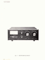
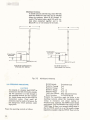
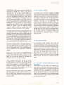
$3
...~%
...
>:
;.,
.- ...~
,, m
' . .
,p
5 : ..
.F z*-
.>,; , .$j.'
,-,.=
6
5".
.1:.
..
.+&-7&&:~-
~:
::
:a
;I:+
-
...
.....
-.
..
,- .
L
.
...-
.
;'?:
-
,.>.z*$&=:+z 7:i.- . :
:
--.%
3.
<:.*+;;
#g.'*e=-.? :&
~:
.
.
-. . . . . . .
~.
~ Z . .
... ..~= . .
-.
.
@
?.
~
R. L. DRAKE COMPANY
:~
- ..
:*.&
+,.@: @$
.
.-
dL_w$,
:l
;;,.: .=<-.
>+
.
,
.:
. .. ."-
.?, .'>
~
:
.. .
19.78
I
. . . .,
..
. -. . .,:.
~.
. ..
..: . ...-.: .....~.
. .
. :. 7. 1 .
. . . . .
.. .. . >;.<r-..
.
. ,
.
.
6
C~
. . , . < . '
-
~
,
. ..
.
....
*a%
. =.
= -=.
PRINTED IN U.S.A.
... -
.,
,...
,.=
. . .
.
,,
<.
<
..:-
r
...
..
-
.
. .
:
:.-. ... *
...
I?
: . ,
.
. .. .
.. .. ..
.;., :-,.. :.:c ;
;
YL.f*
?., . >.? 7 -?*
.:.. - .~
.-<,,
~,.
=
.:.' 7
~-,.-+
'-zu
> _
j:a.2:..s$;,
-.y22
*:&..~::?
, <$
aar
- Es
-rr &&_~
TABLE OF CONTENTS
CHAPTER I
1.1.
1.2.
CHAPTER ll
2.1.
PAGE
................... 1.1
Description . . . . . . . . . . . . . . . . . . . . . . . . . . . . . . . . . . . .
Specifications . . . . . . . . . . . . . . . . . . . . . . . . . . . . . . . . . . . . . .
INSTALLATION . . . . . . . . . . . . . . . . . . . . . . . . . . . . . . . . . . . . . . . . . . .
. . . . . . . .2.1
2.2.
Unpacking . . . . . . . . . . . . . . . . . . . . . . . . . . . . . . . . . . . . . . . . . . . . . . . . . . . . . . . . . . . 2-1
Location . . . . . . . . . . . . . . . . . . . . . . . . . . . . . . . . . . . . . . . . . . . . . . . . . . . . . . . . . . . . . 2.1
2.3.
2.4.
Requirements . . . . . . . . . . . . . . . . . . . . . . . . . . . . . . . . . . . . . . . . . . . . . . . . . . . . . . . . 2.1
Antenna Connections . . . . . . . . . . . . . . . . . . . . . . . . . . . . . . . . . . . . . . . . . . . . . . . . 2.1
OPERATION
..........................................
......
CHAPTER I11
3.1 .
Front Panel Controls . . . . . . . . . . . . . . . . . . . . . . . . . . . . . . . . . . . . . . . . . . . . . . . . . .
3.2.
3.3.
Rear Panel Connections . . . . . . . . . . . . . . . . . . . . . . . . . . . . . . . . . . . . . . . . . . . . .
Use of the Drake B-1000Accessory Balun . . . . . . . . . . . . . . . . . . . . . . . . . . . . . . . .
.
3.4
3.5 .
3.6.
3.7.
.
INTRODUCTION . . . . . . .
CHAPTER IV
Operating Procedure-. . . . . . . . . . . . . . . . . . . . . . . . . . . . . . . . . . . . . . . . . . . . . . . . .
0ff.the.Air Tuning . . . . . . . . . . . . . . . . . . . . . . . . . . . . . . . . . . . . . . . . . . . . . . . . . . . .
Reflected Power . . . . . . . . . . . . . . . . . . . . . . . . . . . . . . . . . . . . . . . . . . . . . . . . . . . . .
Use with Transceivers or TIR Combinations . . . . . . . . . . . . . . . . . . . . . . . . . . . . . .
MAINTENANCE
............
Fig. 1-1
MN2700 Matching Network
CHAPTER I
INTRODUCTION
The typical modern transmitter or high-power
amplifier has either a pi-network tank circuit or a
broadband transformer output and will work into
resistive loads of 50 to 75 ohms with Voltage
Standing Wave Ratios (VSWR) of 2:l or less. This
resistive load can only he achieved with a resonant
antenna; thus, for multiband operation, multiple
antennas are required. Space and cost considerations render this solution impractical for most
amateurs. In addition, many singleband antennas
will not maintain less than 2:l VSWR across the entire band. The MN-2700 impedancematching network can:
1. Measure feedline VSWR, then reduce the
VSWR a t the transmitter output to 1:l.
2. Monitor transmitter power output in watts
directly and continuously.
3. Attenuate 2nd harmonic output from a transmitter by 25 to 35 dB; thus i t may eliminate
the need for a low-pass TVI filter.
4. Match an antenna to a transmitter having
fixed loading.
5. Give optimum match with multiband
antennas.
6. Precisely match a transmitter to an antenna
across a complete amateur band.
7. Permit off the air transmitter tuning using a
dummy load.
8. Eliminate the necessity of retuning the
transmitter when switching from "barefoot"
to linear amplifier operation since the
transmitter always "sees" 50 ohms resistive.
9. Help localize trouble by comparing transmitter output into an antenna and into a dummy load.
10. Allow antenna comparisons with the use of
the internal antenna switch.
11. Permit the use of open-wire feedline antenna
systems, with the use of an accessory balun.
12. Permit the use of long-wires of various
impedances. The accessory balun can be used
to match the higher impedance ranges.
1-2. SPECIFICATIONS.
Frequency Coverage:
Input Impedance:
Load Impedance:
Balanced Feedlines:
Long-Wire Antennas:
Power Capability:
1.8 to 30 MHz. Band
Switch marked for 160,
80, 40, 20, 15, and 10
meter amateur bands;
however,
frequency
coverage
between
amateur bands is possible
by using the nearest band
positions with a small
reduction in matching
capability.
50 ohms (resistive).
50 ohm coaxial with
VSWR of 5:l or less a t
any phase angle (3:l on 10
meters). 75 ohm coaxial a t
a lower VSWR can be
used.
With the Drake B-1000
accessory balun, tunes
feed point impedances of
40 to 1000 ohms, or 5:l
VSWR referenced to 200
ohms (3:l on 10 meters).
Feed point impedances up
to 5:l VSWR referenced
to 50 ohms. Also, 5:l
referenced to 200 ohms
with the Drake B-1000 accessory balun (3:l on 10
meters).
Meter:
Wattmeter Accuracy:
Insertion Loss:
Dimensions:
Front Panel Controls:
Rear Panel
Connectors:
1000 watts average
continuous duty, 2000
watts PEP
Reads VSWR or forward
power, 0-200 watts or
0-2000 watts.
f 5% of reading 1% of
full scale.
0.5 dB or less on each
band after tuning.
Height: 4-17132 in. (11.5
cm)
Width: 13-3/32 in. 133.26
cm)
Depth: 13 in. (33 cm) including connectors.
Weight: 11 lbs. (5 kg)
Provide for the adjusb
ment of resistive and
reactive tuning, antenna
switching, band switching, VSWR calibration,
and selection of watts or
VSWR functions of the
meter.
The rear panel has four
type SO-239 connectors
(one for input and 3 for
outputs), three screw terminal connections (for
long-wire and open-wire
feeder systems), and a
ground post.
+
CHAPTER ll
--INSTALLATION
3. REQUIREMENTS.
Carefully remove the MN-2700 from the shipping
carton and examine it for evidence of damage. If any
damage is discovered, immediately notify the
transportation company that delivered the unit. Be
sure to keep the shipping carton and packing
material for the transportation company to examine
if there is a damage claim. Keeping these items is
recommended in any case, since having them
available makes shipment of the unit much easier
should it ever be necessary to return it to the factory
for service.
NOTE
Fill out the enclosed registration card and
return it to the factory within 10 days of
purchase to insure registration and
validation of the warranty.
Connect the RF output of your transmitter or
amplifier to the XMTR connector of the MN-2700,
using 50 ohm coaxial cable such as RGdlU. Cable
length is not critical. In installations using a
transceiver or transmitter-receiver combinations,
the matching network should be the last item the
out-going RF signal passes through before entering
the feedline to the antenna. The effects of this on
receiver operation will be discussed in Chapter 111,
Operation, of this manual.
Connect the EXT GND post of the matching network to the station ground with a short piece of
heavy braid.
2.4. ANTENNA CONNECTIONS.
Antennas such as beam antennas, single band
dipoles, trap dipoles, and verticals fed with coaxial
cable should be connected to the rear oanel connectors marked ANT 1 or ANT 2.
-
-9-2LOCATION.
The MN-2700 will work properly in almost any location. Select a location on the operating table that
will allow yoq to reach the control knobs easily.
Figure 2-1 illustrates recommended viewing options
using the hardware furnished with the unit.
Connect end-fed long-wireantennas to the rear panel
screw terminals labeled LW3 or LW4. A good RF
ground should be connected to the EXT GND post.
Antennas fed with balanced feedline should be connected as explained in Chapter 111, Section 3-3of
this manual.
STANDARD
I
1
,
-
\
-
- 4 -
OPIIONAL f t f l
~H,E,,,AL
Fig. 2-1
r r u o l o x 1 4 x 5/8 L O N G
IUPPLI€O WITH U N l I
Viewing Angle Options
,
Fig. 3-2
.
Rear Panel Connections
CHAPTER Ill
OPERATION
3-1. FRONT PANEL CONTROLS. (Figure 1-1)
VSWR SET Control:
Varies the sensitivity of the VSWR sensing
circuitry.
Meter:
Displays either forward power in watts or
VSWR as selcted by meter switches.
VSWR SET Switch:
Used to calibrate the meter for VSWR measure
ments.
VSWR READ Switch:
Causes meter to indicate VSWR.
200 and 2000 Watt Switches:
Causes meter to indicate forward power, either
200 or 2000 watts full scale.
ANTENNA Switch:
Selects the desired antenna and grounds all
unused antenna terminals. Positions are provided for Dummy Load (which can also be used for
an additional antenna or as a grounding position for antennas 1 through 4), 2 coaxial-fed
antennas (1,2) and two long-wire antennas (3,4
without accessory balun). With accessory
B-1000 balun, balanced feedline capability or
1:l and 41 match to long-wire antennas are
available.
BAND Switch:
Selects the fixed capacitors and inductors for
each band. In the DIRECT position, bypasses
the matching network and connects the RF
through the meter circuitry directly to the
antenna selected.
REACTIVE Tuning:
Tunes out the series reactive component of the
antenna impedance.
Reactive Range Switch:
Switches in additional fixed capacity to provide
additional reactive tuning range.
RESISTIVE Tuning:
Varies the resistive component of the MN-2700
output impedance to match the series resistive
component of the load.
Resistive Range Switch:
Switches in additional fixed capacity to provide
additional resistive tuning range.
3.2 REAR PANEL CONNECTIONS. (Figure 3-2)
XMTR Jack:
50-239 socket for input from the transmitter
DL Jack:
50-239 socket for the connection of a dummy
load (or another coaxial fed antenna).
ANT 1-and ANT 2:
50-239 sockets for 2 separate coaxial fed
antennas.
LW3 and LW4:
Screw terminals for two longwire antennas,
when used without the accessory balun (1:l impedance ratio to matching range of network).
Numbers correspond to ANTENNA selector
switch position.
3.3. USE OF THE DRAKE B.1000 ACCESSORY
BALUN
Installation:
Remove the three screws at terminals marked
LW3, LW4, NC and then reinstall these screws
through the holes in the balun board to the
matching terminals on the MN-2700. Also, install the two mounting screws in the other two
corners of the balun board to the MN-2700.
Balanced Feedlines:
The two wires of the balanced feeders are connected on the top of the balun board, under the
heads of terminal screws marked BAL and
BALlLW(1:l or 4:l). The ANTENNA selector
switch is placed in position 3 when this antenna
system is used.
Long-Wire Antenna Using Balun:
(Cannot be used when balanced feeders are attached.) Connect the longwire to the terminal
marked BALILW (1:1 or 41). In ANTENNA
switch position 3, the antenna will be matched
with a 1:l impedance ratio. In position 4, the
antenna will be matched with a 4:l impedance
ratio, providing for a higher impedance range
matching capability. It is absolutely necessary
to have a good RF ground.
Multiband Antenna:
A doublet antenna 135 feet long, center fed with
open-wire feeders 67 feet long, can be matched
using the accessory balun on 80 through 10
meters. The feeders make a good 160 meter vertical when connected together and to the
BALILW (1:l or 4:l) terminal of the balun
*
I
TO M A T c m m
NETWORK
1
"lw~-r+I
TO MATCHING
BALILW (1:l or 4:l)
8010 METER CONFIGURATION
(POS31BAL ON MN2700)
,
:.*
.'.*
2
. -=
.c.-,.
"
-
:--
:
'
A
"
.
.
--
<. -,< , .:s.
.:<
.~ <:*.-:.,*
.
- a 3,&+,:
,
.-
-.
.. -. 2 :
~..
--..
-.
&*I.
~
"
.
~, .
-
:.~.:;. .-
?..'.' z-'
160 METER INVERTED 'L'
(POS 4/UNBAL ON MN2700)
,-
~
.
.
1
jl::
.
. .
..- ,.=:>.>:
. .. . -.F-.
~..*.'II,..
- .
=
Fig. 3-3 Multiband Antenna
CAUTION
An antenna or a dummy load MUST be
connected to the MN-2700 before energizing the transmitter to avoid damage to
the matching network and the transmib
ter. Initial tuning must be done with low
transmitter power. Final small adjustments may be made a t full power. Do
not change any switch positions under
high power.
Preset the operating controls as follows:
BAND Switch:
To desired band
Resistive Tuning:
To 5
Reactive Tuning:
To 5
Resistive Range:
To o - 10
Reactive Range:
To o - 10
VSWR Set Control: Fully Counterclockwise
Meter Switches:
To VSWR READ
Energize the transmitter, apply low power to the
matching network, adjust the transmitter plate
tuning to resonance, and adjust loading to
minimum (max. capacity). The VSWR meter should
read upscale. Vary the RESISTIVE tuning until the
VSWR dips. If there is not enough tuning range to
dip the VSWR, switch in or out theresistive range
capacitor as needed to dip the VSWR. Then turn the
REACTIVE tuning control clockwise. Readjust the
RESISTIVE tuning for a dip. If this dip is
downscale from the first dip, you are tuning in the
right direction, and should continue to alternately
move the REACTIVE tuning control clockwise and
tune the RESISTIVE tuning for a dip, until a
minimum VSWR indication is obtained. If the second dip found reads higher on the meter than the
first dip, the REACTIVE tuning control must be
turned counterclockwise a short distance, and the
RESISTIVE tuning adjusted for a dip. Continue
alternating these actions until a minimum VSWR
reading is reached. Again, if additional tuning
range is needed, switch in or out the range
capacitors to obtain minimum VSWR reading.
If the dips found during the tuning procedure are so
far downscale that i t becomes difficult to tell
whether a particular dip is lower or higher than the
preceding one, you can increase the meter sensitivity and get readings that are fartherupscale by turning the VSWR SET knob clockwise. With this added sensitivity it may not be possible to dip to the
meter zero, but any residual reading will represent a
very small power level, probably less than 0.1 watt.
When the matching network has been adjusted
the lowest possible dip, it is properly tuned to present a 50 ohm resistive load to the transmitter. Adjust the transmitter plate tuning and loading controls as directed by the transmitter instruction
manual.
Make a note of the settings of the RESISTIVE and
and the
tuning and range
BAND switch. The next time you operate on this
band, you can tune up quickly by returning the
MN-2700 controls Co the same settings.
With the range switch in 0-10 position, the tuning
control would be recorded as the number on the
knob dial between 0 and 10. With the range switch
in the 10-20 position, 10 should be added to the
number on the dial - record a number between 10
and 20. In the 20-30 switch position, add 20 and
record a number between 20 and 30.
Push the VSWR SET button and rotate the VSWR
SET knob clockwise until the meter needle lines up
with the SET mark (full-scale) on the meter face.
Push the VSWR READ button. The meter will now
indicate VSWR.
b5. OFF-THE-AIRTUNING.
If a 50 ohm dummy load that is capable of handling
full transmitter power output is available, i t and the
MN-2700 can be used to tune up with minimdm interference. Connect the 50 ohm dummy load to
DL connector on the MN-2700, switch the ANTENNA switch to GNDIDL, switch theBAND switch to
DIRECT, and turn on the transmitt@r. The
transmitter (and high-power amplifier, if used) can
now be tuned to match the 50 ohm dummy load.
Then turn off the amplifier and reduce the transmitter power output, without changing the transmitter
tuning. As little as 10 watts input to the MN-2700 is
enough. Set the BAND switch to the desired band,
the ANTENNA switch to the desired antenna, tune
the matching network for minimum VSWR, and
then increase the transmitter power to normal
operating level.
3-6.REFLECED POWER.
I t is possible to read reflected power with the
MN-2700, although the instrument was not primarily designed to do this, T~ read reflected power, first
rotate the VSWR SET knob fully counterclockwise,
and press either the 200 WATTS or 2000 WATTS
meter switch, Increase transmitter Dower to the
desired level (do not exceed full scale on the meter).
then press the VSWR SET button. Rotate the
VSWR SET knob clockwise until the meter indicates the same forward power. Press the VSWR
READ button, The meter now indicates reflected
power,
3.7. USE WI
rRANSCElVERS OR TIR COMBINATIONS.
Adjustment of the MN-2700 with a transceiver is
done exactly as described in Sections 3-4and 3-5
Since the received signal will be passed through the
matching network, i t is necessary to change the
BAND switch to either DIRECT, or to the band the
receiver is tuned to. If this is not done, the received
signal will be attenuated by the matching network
whenever the BAND switch setting is not the same
as the band being tuned.
I
NOTES
CHAPTER IV
MAINTENANCE
The MN-2700 should be practically maintenance
free, since it is a passive device. If either, or both, of
the AA-119 diode rectifiers for the wattmeter are
damaged, they must be replaced with the same type
diodes. Substitution of other type diodes may
seriously degrade the accuracy of the wattmeter. If
any problems arise that cannot be corrected, either
return the unit to your dealer, or write to our Service
Department. Please describe your problem in detail,
including external connections, control settings,
type of antenna, transmitter, ete. Do not return
your MN-2700 to the factory without proper
authorization. Send your requests for authorization
to the following address:
R.L. DRAKE COMPANY
540 Richard Street
Miamisburg, OH 45342
ATTN: Customer Service Dept.
Telephone: (Area Code 513) 866-3211
Telex No. 288-017
NOTES