1
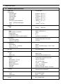
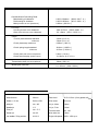
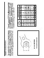
SPEC I FICAT IONS
A.
GENERAL SPECIFICATIONS
Basic color
Dimensions:
Overall length
Overal I width
Overall height
Seat height
Wheelbase
Minimum ground clearance
Caster (steering head angle)
TraiI
Weight:
Net
Crystal Silver
2180mm (85.8 in.)
835mm (32.9 in.)
1150mm (45.3 in.)
810mm (31.9 in.)
1465mm (57.7 in.)
145mm (5.7 in.)
27°
110mm (4.3 in.)
229 kg
(505 Ibs.)
_ _ _ _ _ _ _ _ ~ ~
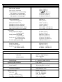
Engine:
Type
Bore x stroke x cylinders
Displacement
Compression ratio
Compression pressure (warm engine)
D.O.H.C., air-cooled, triple
68mm x 68.6mm x 3
747cc
8.5: 1
142 Ibs in² (±14 Ibs in²)
Lubr ication :
Lubrication system
Delivery pump type
Pressure lubricated, wet sump
Trocoid
Carburetion:
Manufacture
Type, I.D. No., Quantity
Rated venturi size
Mikuni
BS34, constant velocity, 1J701, 3 pcs.
34mm
Air filter
Dry foam rubber
Ignition:
Type
Spark plug
Charging
Type
Manufacture, I.D. No.
Maximum output
Battery type
Battery dimensions
Regulator
Rectifier
Starting
Battery/coiI
NGK BP-7ES, Champion N-7Y
Three-phase, regulated alternator
Hitachi LD120-02
14.5 Vo lt/l8 amp
12 volt
14 amp-hour
134 x 166 x 89mm
Hitachi TL1Z-80
Stanley DE-4404, Silicon, full wave
Transmission coupled kick
Mitsuba Electric SM-224C
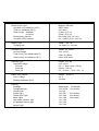
Primary drive
Type
Teeth, ratio
Clutch
Hy-Vo silent chain
45/27
1.666
Wet, multiple disc.
Transmission:
Teeth, ratio, overall
1st
2nd
3rd
4th
5th
Constant mesh, 5-speed, drum shifter
32/13
2.461
13.285
27/17
1.588
8.636
26/20
1.300
7.069
1
1.095
5.955
22/23
0.956
5.201
Secondary Drive:
Shaft drive
Transmission 0utput :
Type, teeth, ratio
Middle gear case
Type, teeth, ratio
Final gear case
Type, teeth, ratio
Chassis:
Frame
Suspension:
Front (type, travel)
Rear (type, travel)
Tires:
Front
Rear
Brakes:
Front
Rear
Fuel tank
Wheels:
Front
Rear
Spur gear, 34/32, 1.063
Bevel gear, 19/18, 1.056
Bevel gear, 32/11, 2.909
Tubular steel double cradle
Telescopic fork, 175mm (6.9 in.)
Swing arm, 75mm (3.0 in.)
3.25 H 19 Bridgestone
4.00 H 18 Bridgestone
Dual hydraulic disc
Single hydraulic disc
US gal.) Regular leaded or unleaded
1.85 x 19 Cast Aluminum
2.15 x 18 Cast Aluminum
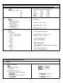
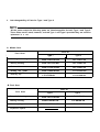
B. MAINTENANCE SPECIFICATIONS
1. Engine
Engine Oil Capacity
(3.7
(3.4 US qt.)
(3.0 US qt.)
Oil and filter change
Oil change
R ecommended Iubricant :
If temperature does not go below
SAE
SE motor oil
SAE
SE motor oil
If temperature does not go above
Middle gear case capacity:
Final Gear case capacity
Recommended Iubr icant
If temperature does not go below
5°C (40°F)
If temperature does not go above
15°C (60°F)
A II weather
375cc ( 13 oz.)
300cc ( 100 oz.)
Cranking pressure (at sea level)
Maximum difference between cylinders
10 ± 1 kg/cm² (142 ± 14 psi)
1 .0 kg/cm² (14 psi)
SAE 90 Hypoid gear oil, G L-4
SAE 80 Hypoid gear oil, GL-4
SAE 80W90 Hypoid gear oil, GL-4
Camshafts
I
Wear I im it
A
Exhaust B
C
Camshaft bearing surface diameter
Camshaft-to-cap clearance :
Standard
Maximum
Camshaft runout limit
8.018mmm
28.285 ±0.05mm
36.303 ± 0.05mm
24.97~24.98mm (0.9830~0.9835 in.)
.020~.054mm (.0008~.002 in.)
.160mm (.006in.)
I
0.1 mm (.004 in)
I
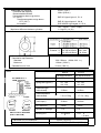
Valves
INNER
OUTER
INTAKE/EXHAUST
ALLOWABLE T I L T
FROM VERTICAL
OUTER
INTAKE
OUTER
EXHAUST
DIRECTION OF WINDINGS
(TOP TO BOTTOM)
INTAKE/EXHAUST
Free length
35.6mm
39.9mm
Spring rate (kg/mm)
K1 1.84
K2 2.36
K1 3.32
K2 4.18
31.5mm
34.5mm
Installed length
(valve closed)
I
-------------
28.13mm
36.15mm
Installed pressure
(valve closed)
1
7.5 ± 0.75kg
17.5 ± 1.2kg
Compressed length
(valve open)
23.0mm
26.0mm
Wire diameter
2.8mm
3.9mm
Number of windings
7.75
6.4
Winding O.D.
15+ 0.3mm
0
21.6
I
I
Valve stem run-out maximum
Valve seat width standard/maximum
~
0
- 0.3mm
1
.03mm (.0012 in.)
1.3mm (.050 in.) / 2.0mm (.080 in.)
C Iea rance
(Cold engine)
0.1 6~ 0.20m m
"A" head diameter
36 + 0.2
I "B"
"B"
face width
2.26 ± 0.57mm
"C" seat width
1.3 ±0.15mm
"D" margin thickness
1.2 ± 0.2mm
Stem diameter (O.D.)
7 + .010mm
-.025mm
7 + .019mm
-.010mm
Guide diameter (I.D.)
I Stem-to-guide clearance I
0.020~0.041mm
I
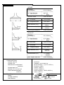
EXHAUST
Cylinder and Piston
Cylinder material
Cylinder liner
Standard bore sizehtandard
maximum
Cylinder taper limit
Cylinder out-of-round limit
Piston clearancehtandard
maximum
Piston Rings
Design
End gap (installed)
Side clearance
CIea rance
(Cold engine)
0.2 1~0.25mm
"A" head diameter
31 + 0.2mm
"B" face width
2.26 ± 0.57mm
"C" seat width
1.3 ± 0.15mm
"D" margin thickness
1.2± 0.2mm
Stem diameter (O.D.)
7 +.025mm
-.040 mm
Guide diameter (I.D.)
7
Stem -to-guide clea ra nce
0.035~0.059mm
+ .019mm
Aluminum
Pressed in; special cast iron
68.00~68.02mm / (2.677~2.678 in.)
68.10mm (2.681)
0.05mm (.002 in.)
0.01mm (.0004 in.)
0.050~0.055mm / (.0020~.0022 in.)
0.1mm (.004 in.)
Oil
-0.4mm
0.04-0.08mm
-0.4mm 0.2~0.9mm
0.03-0.07mm
Crankshaft and Connecting Rods:
Main bearing oil clearance
Rod bearing oil clearance
Main journal run-out (maximun)
0.022~0.044mm (.0009~.0017 in.)
0.032~0.054mm (.0013~.0021 in.)
0.03mm (.0012 in.)
Oil Pump
Housing-to-outer rotor clearance
Outer rotor-to-inner rotor clearance
,090~.015mm (.0035~.0059 in.)
.03 ~.09mm (.0011~.0035 in.)
Clutch
Friction plate thickness standard
minimum
Clutch plate warp maximum
3.0mm (0.12 in.)
2.8mm (0.11 in.)
0.05mm (.002 in)
Clutch spring length standard
minimum
42.8mm (1.685 in.)
41.5mm (1.634 in.)
Clutch push rod run-out maximum
Clutch lever freeplay (end of lever)
0.4mm (.016in.)
13~26mm (0.5~1.0 in)
Transmission shaft run-out maximum
.08mm (.001 in.)
Middle gear case lash
0.1 ~0.2mm (.004~.008 in.)
2. Carburetion
I
Manufacturer
Mikuni
Float level
26.5 ±2.5mm (from gasket surf
Model, I. D. No.
BS34,1J701
Pilot screw
2¼ turns
Main jet
No. 145
Air jet, Main
1 .0mm
Needle jet
Y-2
Air jet, Pilot
1.6mm
Pilot jet
No. 17.5
Throttle valve
No. 140
Starter jet
No. 45
Inlet valve size
2.0mm
Jet needles / Clip position
4H11/3
Engine idle speed 1050 ~ 1150 r.p.m.
3. Chassis
Wheels and Tires
Rim run-out, vertical
Rim run-out, horizontal
Tire pressure, front, normal riding
High speed or with passenger
Tire pressure, rear, normal riding
High speed or with passenger
2.0mm (.080 in.)
l.0mm (.040 in.)
1.8
(26 p.s.i.)
2.0 kg/cm2 (28 p.s.i.)
2.0 kg/cm2 (28 p.s.i.)
2.3 kg/cm2 (33 p.s.i.)
Brakes
Recommended fluid
Minimum boiling point
DOT No. 3
240°C (464°F)
5.5mm (0.18 in.)
0.15mm (.006 in.)
6.5mm (0.26 in.)
5.0~10.0mm (0.2~0.4 in.)
5.0~10.0mm (0.2~0.4 in.)
Pad thickness wear limit
Brake disc maximum deflection
Brake disc minimum thickness
Front brake freeplay (end of lever)
Rear brake freeplay (end of pedal)
~~
Front forks
Spring (upper) free length
preload length
Spring (lower) free length
preload length
Spring rate (0 ~100mm travel)
(100~175mm travel)
Fork oil capacity (each side)
55.8mm (2.2 in.)
50.8mm (2.0 in.)
448.3mm (17.65 in.)
423.3mm (16.67 in.)
0.5 kg/mm (28 Ibs/in.)
0.6 kg/mm (33.6 Ibs./in.)
170cc (5.75 US fl. oz.)
Rear shock absorbers
Spring free length
Spring preload length
Spring rate (0~45mm travel)
(45~75mm travel)
253mm (9.95 in.)
228 mm (9.0 in.)
1.9 kg/mm (106 Ibs./in.)
2.6 kg/mm (145 Ibs./in.)
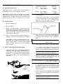
10° @ 1100 rpm
38.5° ± 1.5°@ 2,900 rpm
1550 + 200 rpm
0
NGK BP-7ES or Champion N-7Y
0.7~ 0.8mm (.028~.032 in)
Ignition timing retarded
adva nced
advance starts
Spark plug
Electrode gap
Spark plug cap resistance
I
5.0 K ohms
Contact point gap
Spring tension
0.3~0.4mm (.012 ~.016 in)
750 ± 100g (26.5 ± 3.5 oz)
Condenser capacity
Insulation resistance
0.22µF ± 10%
10 M ohms or more
Ignition coil type
Spark gap 6V
12V
Primary resistance (20°C)
Secondary resistance (20°C)
H itachi CM11-52A
6mm @ 100 rpm
7mm @ 5,000 rpm
4.0 ± 0.4 ohms
11.0 ± 1.1K ohms
~ ~~
Starter motor type
Armature coil resistance (2O°C)
Field coil resistance (2O°C)
Brush length standard
minimum
Brush spring pressure
Armature mica undercut
Mitsuba SM-224C
0.007 ohms
0.01 ohms
12.5mm (0.5 in)
5.5mm (0.22 in)
620 ± 60g (22.0 ± 2.0 oz)
0.5 ~ 0.8mm (0.02 ~ 0.03 in)
Battery type
Charging rate
Yuasa
YB 14L
1.4 amps for 10 hours
Generator type
No load voltage
Field (inner) coil resistance(20°C)
Stator (outer) coil resistance (20°C)
Hitachi Ld 120-02
14.5 ± 0.5V
4.04 ± 0.4 ohms
0.48 ± 0.05 ohms
Regulator type
Regulated vo It age
Core gap
Yoke gap
Point gap
Hitachi TLIZ-80
14.5 ± 0.5V
0.6 ~ 1 .0mm (.024 ~.040 in)
0.9mm (.035 in)
0.3 ~ 0.4mm (.012 ~.016 in)
Starter relay switch
Cut-in voltage
Winding resistance (20°C)
Hitachi A104-70
6.5 V
3.5 ohms
Lighting
Headlight
Ta iIIight/stop I ight
License light
Flasher Iight
Flasher pilot light
Meter Iights
High beam indicator light
Oil pressure warning light
Neutral light
Sealed beam
12V 8/27W
12 v 8W
12V 27W
12V 3.4W
12V 3.4W
12 v 3.4w
12 v 3.4w
12 v 3.4w
12V50/40W
(two bulbs)
(four bulbs)
(two bulbs)
(two bulbs)
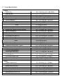
C. Torque Specifications
I
I
Engine
Spark plug
Cam cap nut
Rod cap
Starter clutch bolt
Shift cam locating bolt
Detent assembly
Transmission bearing caps
Crankcase bolts 8mm
10mm
Clutch holding nut
Clutch spring screws
Middle gear case mounting screws
Rotor holding bolt
Bearing housing bolt
Oil pipe union bolt
Oil pump drive gear nut
Crankshaft turning nut
Cylinder head 8mm
10mm
Cylinder holding nuts
Camshaft cap nuts
Engine mounting bolts 10mm
12mm
Engine oil drain plug
Oil filter mounting bolt
Middle gear drain plug
Chassis
Front axle nut
Front axle holder nuts
Rear axle nut
Rear axle pinch bolt
Brakes
Caliper support bolt
Caliper mounting bolt
Brake hose union bolt
Disc mounting bolt
Front fork pinch bolt
Steering stem top bolt
Swing arm pivot lock nut
Rear shock absorber nut
I
1.5 ~ 2.5 m-kg (11.0 ~18.0 ft-lbs.)
0.8 ~ 1.O m-kg (6.0 ~ 7.0 ft-lbs.)
3.8 m-kg (27 ft-lbs.)
2.8 ~ 3.2 m-kg (20 ~ 23 ft-lbs.)
1.3 ~ 2.1 m-kg (9 ~ 15 ft-lbs.)
4.0 ~ 4.5 m-kg (29 ~ 32 ft-lbs.)
1.8 ~ 2.2 m-kg (13 ~ 16 ft-lbs.)
2.0 rn-kg (14 ft-lbs.)
3.7 m-kg (27 ft-lbs.)
8 m-kg (58 ft-lbs)
0.8 ~ 1.O m-kg (6.0 ~ 7.0 ft-lbs.)
2.0 ~ 2.5 m-kg (14 ~ 18 ft-lbs.)
3.0 ~ 4.0 m-kg (22 ~ 29 ft-lbs.)
2.0 ~ 2.4 m-kg (14 ~ 17 ft-lbs.)
2.0 ~ 2.2 m-kg (14 ~ 16 ft-lbs.)
8.0 ~ 12.0 m-kg (58 ~ 87 ft-lbs.)
1.5 ~ 2.9 m-kg (11 ~ 21 ft-lbs.)
2.0 m-kg (14 ft-lbs.)
3.5 m-kg (25 ft-lbs.)
2.0 m-kg (14 ft-lbs.)
1.O m-kg (7 ft-lbs.)
5.0 ~ 6.0 m-kg (36 ~ 43 ft-lbs.)
8.0 ~ 11.0 m-kg (58 ~ 80 ft-lbs.)
3.9 ~ 4.7 m-kg (28 ~ 34 ft-lbs.)
3.0 ~ 3.4 m-kg (22 ~ 25 ft-lbs.)
3.9 ~ 4.7 m-kg (28 ~ 34 ft-lbs.)
7.0 ~ 10.0 m-kg (50 ~ 72 ft-lbs.)
1.3 ~ 2.3 m-kg (9 ~ 17 ft-lbs.)
12.0 ~ 18.0 m-kg (87 ~ 130 ft-lbs.)
0.45 ~ 0.75 m-kg (3.0 ~ 5.0 ft-lbs.)
1.5 ~ 2.0 m-kg (11 ~ 15 ft-lbs.)
4.5 ~ 5.0 m-kg (28 ~ 35 ft-lbs.)
2.3 ~ 2.8 m-kg (16 ~ 20 ft-lbs.)
1.7 ~ 2.2 m-kg (12 ~ 16 ft-lbs.)
1.3 ~ 2.3 m-kg (9 ~ 17 ft-lbs.)
6.6 ~ 10.5 m-kg (48 ~ 76 ft-lbs.)
8.0 ~ 10.0 m-kg (58 ~ 72 ft-lbs.)
2.3 ~ 3.7 m-kg (20 ~ 27 ft-lbs.)
1
Components should be
500 - 600
room temperature.
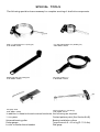
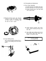
SPECIAL TOOLS
Valve guide remover
Clutch holding t o o l
Final drive gear holding t o o l
Valve guide installer
Clutch plate installation t o o l
Middle and final gear holding t o o l
Valve spring compressor
Clutch lock nut wrench
Damper special tool
Valve seat cutter set
Cam chain cutter
Rotor puller
Tappet adjusting t o o l
Slide hammer
Rotor holding t o o l
Gear lash measurement t o o l
(middle gear)
Gear lash measurement t o o l
(fin al gear)
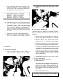
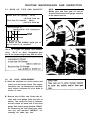
Vacuum gauge
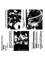
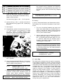
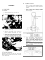
d. Turn petcocks to "prime" position.
e. Start motorcycle and allow it t o warm up for
2-3 minutes. The warm-up is complete when
engine responds normally t o threttle opening.
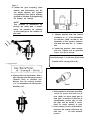
a. The engine must be warmed up before setting
idle speed.
b. Set engine idle speed by turning the throttle
stop screw in (to increase engine speed) or out
(t o decrease speed).
f. Adjust damping valve on each vacuum gauge
until the needle flutters only slightly. The
gauge needles must respond quickly to rapid
opening of the throttle.
Standard Idle RPM
1,050 - 1,1 50rpm
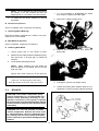
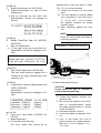
g. Each gauge will indicate the same reading i f
the carburetors are synchronized. The left and
right carburetors are to be synchronized t o the
center carburetor, which has no synchronizing
screw. Turn the l e f t carburetor synchronizing
screw until the gauge reading is the same as
for the center carburetor. Repeat for the right
carburetor.
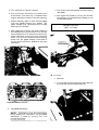
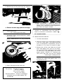
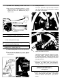
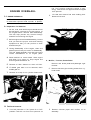
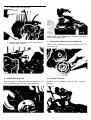
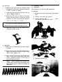
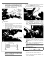
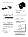
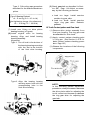
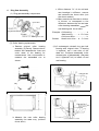
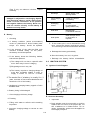
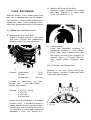
B. Air Filter
1. Removal
a. Li f t the seat and remove the air filter case cap
by removing the pan head screws (2).
-_-
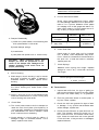
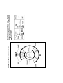
SYNCHRONIZING SCREWS
3. Idle speed adjustment.
NOTE: Carburetors must be synchronized
before setting final idle speed. The idle speed
adjustment i s made b y turning only one
throttle stop screw.
b. Pull out the element.
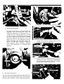
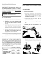
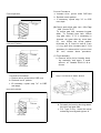
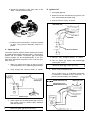
C. Engine/Transmission Oil
1. Oil level measurement
a. T o check the level, warm the engine up for
several minutes. Stop the engine. With the
engine stopped, screw the dip stick completely
out and then rest the stick in the hole.
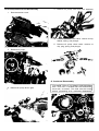
2. Cleaning method
a. Tap the element lightly t o remove most of the
dust and dirt; then blow out theremainingdirt
with compressed air through the inner surface
of the element. I f element isdamaged, replace.
NOTE: When checking engine oil level with
the dip stick, let the unscrewed dip stick rest
on the case threads. Be sure the engine is
stopped and the machine is positioned straight
up and on both wheels.
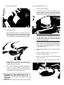
b. The dip stick has a Minimum and a Maximum
mark. The oil level should be between the two.
If the level is low, add sufficient oil to raise it
t o the proper level.
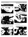
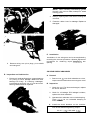
2. Engine/Transmission oil and oil filter replacement
a. Start the engine. Allow it t o warm up for
minutes. Stop the engine.
b. Place an oil pan under the engine and remove
the oil filler cap.
c. Remove the drain plug and drain the oil.
b. Reassemble by reversing the removal procedure. Check whether the element is seated
completely against the case.
c. The air filter element should be cleaned once
a month or every 1,600km (1,000 miles). It
should be cleaned more often i f the machine
is operated in extremely dusty areas.
without the air cleaner element installed. Excessive oil contamination and engine wear
may result.
d. Remove the oil filter bolt and filter element.
e. Reinstall the drain plug (make sure it istight).
4.0 ~ 4.5m-kg (28.9-32.5ft-lb)
f. Install the oil filter element andcover. Tighten
the oil filter bolt.
NOTE: Make sure the " 0 ' ring is positioned
properly.
h. After replacement of engine oil, and/or oil
filter, be sure t o check the oil pressure and oil
leakage. The oil pressure indicator lightshould
go of f afte r the engine i s started.
CAUTION:
If the "Oil" indicator light
remains on, immediately stop the engine.
Refer t o lubrication information in Sec. 3-5
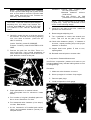
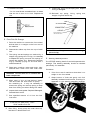
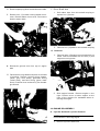
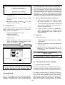
D. Middle Gear/Final Gear Oil
1. Oil level measurement
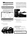
a. Place the machine on a level surface and place
it on the center stand. The engine should be
cool ( at atmospheric temperature). Allow 2
minutes for oil t o drain t o bottom of cases.
b. Remove the oil filler cap. Check the oil level
with level gauge (from tool kit) as shown.
The correct oil level i s between the two marks
on each end of the level gauge. Use end of
gauge marked "REAR" for measuring the
rear (final) gear case. Use the end marked
measuringthe middlegear case.
NOTE: Middle gear and final gear oil can be
checked with same level gauge, which is in
the owners tool kit.
g. Add oil through the dip stick hole.
Oil quantity:
Periodic Oil Change
2.8 lite r ( 3 US qt)
With oil filter change:
3.2 liter (3.4 US qt)
Recommended oil: except in cold weather
Yamalube 4-cycle or SAE 20W40 "SE"
(see page 8 )
d. Fill the gear case(s) up to specified level.
CAUTION: Take care not to allow foreign
material t o enter the middle and/or final
aear case.
Oil Capacity:
Middle gear case: 375cc (12.7 U S . fl 02)
300cc (10.0 U.S. fl 02)
Final gear case:
Recommended oil: (see page 8 )
2. Gear oil replacement
a. Place an oil pan under the transmission for
the middle gear and under the final gear case.
e. Reinstall the filler cap(s) securely.
NOTE: After initial 250 mile oil change, it
i s normally not necessary to change middle
and final gear oil more frequently than the
indicated service interval of 6,000 miles.
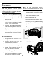
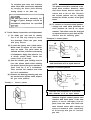
E. Clutch Adjustment
b. Remove the middle and/or final gear oil filler
cap(s) and the drain plug(s), and drain the oil.
not to allow foreign material to enter the
middle andlor final gear case. Do not allow
the gear oil to contact the tire and wheel.
c. Reinstall the middle and/or final drain plug(s).
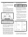
This model has a clutch cable length adjustor and a
clutch mechanism adjustor. The cable length adjustor5
are used to take up slack from cable stretch and to
provide sufficient free play for proper clutch operation
under various operating conditions. The clutch mechanism adjustor is used to provide the correct amount
of clutch "throw" for proper disengagement. Normally, once the mechanism i s properly adjusted, the only
adjustment required is maintenance of free play at
the clutch handle lever.
1. Free play adjustment
Loosen either the handle lever adjustor lock
nut or the cable length adjustor lock nut.
Next, turn the length adjustor either in or out
until proper lever free play is achieved.
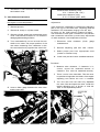
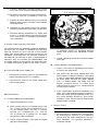
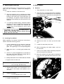
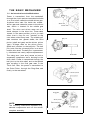
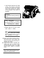
1. Remove the breaker cover
2.
Remove the cam chain tensioner cover.
2. Mechanism adjustment
The second adjustment is located behind the
adjusting cover. Removing the cover will
expose the adjusting set screw and lock nut.
Loosen the lock nut and rotate the set screw
in until it lightly seats against a clutch push
rod that works with the set screw to operate
the clutch. Back the set screw out ¼ turn and
tighten the lock nut. This adjustment must be
checked because heat and clutch wear will
affect this free play, possibly enough t o
cause improper clutch operation. Recheck
clutch cable adjustment a t handlebar after
adjusting.
Loosen the tensioner stopper bolt lock nut
and then loosen the stopper bolt.
4. Slowly rotate the crankshaft counterclockwise
several turns. When the tensioner gets deepest
into the tensioner holder, tighten the stopper
bolt and secure it with the lock nut.
F. Cam Chain Adjustment
The cam chain becomesstretched with use, resulting in
improper valve timing and engine noise. To prevent this
the cam chain tensioner must be adjusted regularly.
S
5. Reinstall the chain tensioner cap and the con-
Exhaust valve clearance (cold)
0.21 - 0.25mm (.008 -.010")
tact breaker cover.
Intake valve clearance (cold)
0.16 - 0.20mm (.006 - ,008")
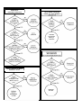
G. Valve Clearance Adjustment
NOTE: Valve clearance must be measured with
the engine a t room temperature.
Adjustment
1. Remove gas tank.
Valve clearance is adjusted by replacing the adjusting
pad on the top of the valve lifter. Adjusting pads are
available in 25 thicknesses ranging from No. 200
(2.00mm) to No. 320(3.20mm) in steps of 0.05mm.
The thickness of each pad is marked on the pad face
that contacts the valve lifter (not the cam). Adjustment
of valve clearance is accomplished as follows:
2. Remove air scoop on cylinder head
3. Remove cylinder head cover and breaker point
cover. Care should be taken to not scratch or
damage gasket sealing surfaces.
4. Turn crankshaft with nut on l e f t end ofcrankshaft to turn cams. The proper position of the
cam when measuring valve clearance is with
the cam lobe directly opposite the valve lifter.
1. Determine valve clearance
measurement.
(feeler
gauge
2. Remove adjusting pad and note number.
3. Select proper pad from appropriate chart
(intake or exhaust chart).
4.
Install new pad and check installed clearance.
Procedure
1. Measure valve clearance. I f clearance is incorrect, record the measured amount of
clearance. This must be measured carefully.
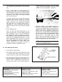
2. There is a slot in the valve lifter. This slot must
be positioned opposite the blade of the tappet
adjusting tool before the tool i s installed.
3. Turn the cam until the lobe fully depresses
5. Insert a feeler gauge between the valve lifter
and the cam heel.
the valve lifter and opens the valve. Install the
tappet adjusting tool as shown to hold the
lifter in this depressed position.
AD JUST ING
TOOL,
CYLINDER
PAD REMOVAL
SLOT
NOTE: The tappet adjusting tool is fastened
to the cylinder head using one ( 1 ) allen screw
such as one used t o install the cylinder head
cover. Make sure that the tool contacts the
lifter only, and not the pad.
CAUTION: If th e cam lobe touches th e tappet
adjusting tool, th e stress may fracture the
cylinder head. DO N O T A L L O W TH E C A M
T O CO NTAC T TH E TAPPET ADJUSTING
TOO L.
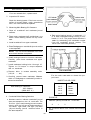
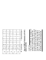
EXAMPL E: Exhaust valve, installed pad:
No. 250 (read down)
Measured clearance: 0.32mm
(read across)
New pad number: No. 260
(intersection o f d o w n & across)
NOTE: The new pad number is to be used as
a guide only. Verify the correctness o f this
choice in the following steps).
7. Install the new pad in the lifter. Install the
pad w it h the number down.
8. Remove tappet adjusting to ol.
4. Carefully rotate the cam so that the pad can
be removed. To avoid cam touching adjusting
tool, tu rn cams as follows: (view f r o m left
side o f machine)
Intake: Carefully rotate CLOCKWISE.
Exhaust: Carefully rotate COUNTERCLOCKWISE.
5. Remove the pad fro m the lifter. There is a
slot in the lifter. Use a small screwdriver or
other blade and a magnetic rod to remove the
pad. Note the number on the pad.
9. T u r n crankshaft to rotate cam several rotations. This w il l set the pad in the lifter.
10. Check valve clearance (step 3). I f clearance is
incorrect, repeat preceding steps until proper
clearance is obtained.
11. Inspect head cover gasket. If bent o r torn,
replace gasket.
12. Reinstall removed parts in reverse order.
H. Compression Pressure Measurement
Insufficient compression pressure w il l result in performance loss and may indicate leaking valves o r worn
o r damaged rings.
Procedure
1. Make sure valve clearance is correct.
2. Warm up engine 2-3 minutes. Stop engine.
3. Remove spark plugs.
4. Install compression check gauge.
6. Proper pad selection is made as follows:
(Use appropriate chart fo r exhaust o r intake
valves.)
a. Fi n d number o f original (installed) pad number on chart. Read d o w n on chart.
b. Find measured valve clearance (fr om step 1)
o n chart. Read across.
c. A t the intersection of installed pad number
(down) and measured clearance (across) is a
new pad number.
Intake
CLEARANCE
...
,
.
.
.
. . ..
..
..
..
. ,.
.
.
.
Exhaust
.
.
.
.
.
.
.
.
.
.
.
..
.
i..
:
.
I
.
5. Turn over engine with kick or electric starter
(make sure battery is fully charged) with
throttle wide open until pressure indicated on
the gauge does not increase further.
2.
Remove the drain cover and clean it with
solvent.
Standard:
I 0 k g / c m ² (142 psi)
Minimum: 9kg/cm² (128 psi)
Maximum: 11kg /cm² (156 psi)
. I f pressure is too low, squirt a few drops of oil
into the cylinder being measured. Measure
compression again. I f there is a higher reading
than before (without oil), the piston rings
may be worn or damaged. If the pressure remains th e same after measuring with the oil,
either or both the rings and valves may be
the cause.
Check each cylinder. Compression pressure
should not vary more than 1kg/cm² (14 psi)
from one cylinder t o any other cylinder.
2 - 4 CHASSIS
A. Fuel Petcock Cleaning
1. Turn the petcock lever t o the "ON" or
"RES" position. Remove the fuel pipe.
B. Fuel Petcock Disassembly
I f the fuel petcock is leaking or excessively contaminated, it should be removed from the fuel tank and
inspected.
1. Remove fuel tank and position it so that fuel
will not spill when the petcock is removed.
2.
Remove petcock and inspect filter screen.
Replace filter if seriously contaminated.
3.
Remove 4 screws on front and rear of petcock
and remove plate, gaskets, lever and diaphragm.
4.
Inspect all components and replace any that
are damaged. I f the diaphragm is in any way
damaged, or the petcock body gasket surfaces
scratched or corroded, the petcock assembly
must be replaced. I f there i s abrasive damage
to any component, the fuel tank must be
drained and flushed.
5. Reassemble petcock and install on fuel tank.
C. Front And Rear Brake
See pages 158-159 for adjustments
1. Brake adjustment
The brakes can be adjusted by simply adjusting
the free play of the brake lever and pedal.
piston in the caliper moves forward as the
brake pad wears out, automatically adjusting
the clearance between the brake pad and the
brake disc.)
a. Front brake lever free play
CAUTION: Proper lever free play is essential
t o avoid excessive brake drag.
1) Loosen the adjusting screw lock nut.
2. Brake pad check
To check pad wear, open the wear indicator
cap. If any pad is worn t o the red line, replace
both pads in the caliper.
2) By turning the adjusting screw in or out,
adjust the play of the brake lever and then
tighten the lock nut. Measure free play a t
end of lever.
FREEPLAY
-
I
Free play: 5~8mm (0.2~0.3 in.)
1
b. Rear brake pedal free play
I
CAUTION: Proper pedal free play is essential
to avoid excessive brake drag.
I
FREE PLAY : 10mm (0.437 in.)
1) Loosen the adjuster lock nut a t the push rod.
2) By turning the adjuster in or out, adjust
the play of the brake pedal and then tighten
the lock nut.
3
Check the brake fluid level
Insufficient brake fluid rnay allow air t o enter
the brake system, possibly causing the brake
t o become ineffective. Check the brake fluid
level and replenish when necessary and observe
these precautions:
a. Use only the designated quality brake fluid;
otherwise, the rubber seals rnay deteriorate,
causing leakage and poor brake performance.
Recommended brake fluids:
DOT No. 3 with 240° C (464°F)
boiling point
b. Refill with the same type and brand of brake
fluid; mixing fluids may result in a harmful
chemical reaction and lead t o poor performance.
c. Be careful that water or other contamination
does not enter the master cylinder when refilling. Water will significantly lower the
boiling point and may result in vapor lock.
2. Front axle
a. Check axle nuts.
Front axle nut torque:
7.0~10.0 m-kg
(50~72 ft-lb)
Rear axle nut torque:
12~18 m-kg
(87~130 ft-lb)
b. Check axle holder nuts (right side).
I
Front axle holder nuts:
1.3 - 2.3 m-kg (9-17 ft-lbs)
1
CAUTION: First tighten the nut on the front
end of the axle holder, and then tighten the
nut on the rear end.
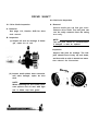
D. Wheels And Tires
Rear axle pinch bolt:
0.45 - 0.75 m-kg (3-5 ft-lbs)
1. Checking the aluminum wheels.
3. Tires
a. Check for cracks, bends or warpage of the
wheels. If a wheel is deformed or cracked, it
must be replaced.
I
,
NOTE: These aluminum wheels are NOT designed for use with tubeless tires.
b. Raise the wheel off the ground. Spin.
Rim runout limits:
Vertical - 2mm (0.08 in.)
Lateral - 1m m ( 0.04 in.)
Tire pressure
,
I
Front
1.8 kg/cm²
(26 psi)
Rear
2.0 kg/cm² | Normal riding
(28 psi)
I
b. Check the tire wear
9. Inspect the O-ring on the spring seat. Replace
O-ring i f damaged.
If a tire tread shows crosswise lines, it means
that the tire is worn to i t s limit. Replace the
tire.
10. Reinstall top spring, O-ring, spring seat,
stopper ring and rubber cap.
STOPPER RING
E. Front Fork Oil Change
1. Raise the machine or remove the front wheel
so that there i s no weight on the front end of
the machine.
2. Remove the rubber cap from the top of each
fork.
CAUTION: Always use a new stopper ring
(wire circlip).
3. The spring seat and springs are retained by a
stopper ring (spring wire circlip). I t is necessary
to depress the spring seat and fork springs to
remove the stopper ring. Remove the stopper
ring by carefully prying out one end with a
small screwdriver.
4. Place open container under each drain hole.
Remove drain screw from each outer tube.
CAUTION: Do not allow oil to contact disc
brake components.
5. When most of the oil has drained, slowly
raise and lower the outer tubes to pump
the remaining oil. I t may be necessary to
remove the spring seat and top spring t o keep
them from falling out when raising fork tubes.
6. Inspect drain screw gasket. Replace ifdamaged.
Reinstall drain screw.
7. Pour specified amount of oil into the fork
inner tube.
Front fork oil (each fork): 170cc
2OW Yamaha Fork Oil
8. After filling, slowly pump the outer tubes up
and down to distribute the oil.
F.
Steering Head Adjustment
The XS750D steering head is fitted with tapered roller
bearings. The steering assembly should be checked
periodically for looseness.
Procedure
1. Raise front end of machine so that there i s no
weight on the front wheel.
2. Grasp bottom of forks and gently rock fork
assembly backward and forward, checking for
looseness in the steering assembly bearings.
3. If there is looseness i nthe steering head, loosen
the crown pinch bolt and steering fitting bolt.
Contact Breaker Gap:
0.3 - 0.4mm (.012~.016 in.)
4. Use steering nut wrench to loosen top steering
fitting nut. The top nut serves as a lock nut.
5. Tighten the lower steering fitting nut until the
steering head is tight, but does not bind when
forks are turned.
6. Retighten the top steering fitting nut, steering
fitting bolt and crown pinch bolt, in that order.
7. Recheck steering adjustment to make sure
there is no binding when the forks are moved
from lock to lock. I f necessary, repeat adjustment procedure.
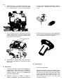
G.Throttle Cable And Grip Lubrication
The throttle twist grip assembly should be greased a t
the time that the cable is lubricated since the grip
must be removed t o get a t the end of the throttle
cable. Two screws clamp the throttle housing t o the
handlebar. Once these two are removed, the end of
the cable can be heid high t o pour in several drops of
lubricant. With the throttle grip disassembled, coat
the inside surface of the throttle grip guide tube with
a suitable all-purpose grease to cut down friction.
H. Lubrication Of Levers, Pedals, Etc.
1. Lubricate the pivoting parts of the brake and
clutch levers with motor oil (10W30).
2.
Lubricate the shaft of the brake pedal with
lithium soap grease.
I f necessary, adjust b y loosening securing
screws and moving the adjustable contact
point.
4. Tighten adjusting screws and recheck breaker
point gap.
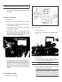
B. Contact Breaker Point Maintenance
1. Apply a few drops of lightweight lubricant to
the point cam lubricators.
2. The points can be lightly sanded with fine
emery paper t o remove corrosion. Then place
a piece of clean paper between the points and
let them close. Remove the paper. Repeat
until no residue shows. The paper may be
dipped in lacquer thinner or contact point
cleaning fluid t o remove oil or sanding residue
from the point surface.
3. Point replacement should be necessary only
2-5 ELECTRICAL
A. Contact Breaker Point Adjustment
when point gap exceeds maximum tolerance,
when the points become severely pitted, or if
the points become shorted or show faulty
operation. New points must be cleaned and
adjusted when installed.
1. Remove breaker point cover.
2. Each cylinder has a set of breaker points. The
No. 1 (left) cylinder set is marked with a "1"
on the backing plate. The No. 2 (center)
cylinder set i s marked with a "2", and the
No. 3 cylinder set is marked "3". The spark
plug wires are also numbered.
3. Check contact breaker point gap (at largest
gap) with feeler gauge.
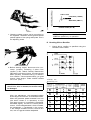
C. Ignition Timing
NOTE: Point gap must beset before setting timing.
1. Ignition timing is checked with a timing light
by observing the position of the stationary
pointer and the marks stamped on the governor assembly. The governor assembly is
marked as follows:
8. The above procedure i s recommended for setting ignition timing. However, the following
information i s provided so that the position of
the static pointer can be verified using a degree
wheel.
There are also three (3) pair of unmarked
lines. They indicate the Full Advance firing
range for each cylinder.
Retarded ignition: 10° BTDC
Fully Advanced Ignition: 38.5±1.5° BTDC
Connect timing light t o No. 1 (left) cylinder.
D. Battery
2. Ignition timing of No. 1 cylinder must be set
first. Connect timing light t o No. 1 spark plug
lead wire.
A poorly maintained battery will deteriorate quickly.
The battery fluid should be checked a t least once a
month.
3. Start engine
4. The stationary pointer should line up with the
" 1F " timing mark on the governor. I f it does
not align, loosen 3 breaker backing plate
screws and move the complete backing plate
until "1F" and the pointer marks align.
1. The level should be between the upper and
lower level marks. Use only distilled water for
refilling. Normal tap water contains minerals
which are harmful to a battery; therefore, refill only with distilled water.
2. Always make sure the connections are correct
when installing the battery. The red lead i s for
the (+) terminal and the black lead is for the
(-) terminal. Make sure the breather pipe i s
properly connected, properly routed, and is
not damaged or obstructed.
NOTE: The battery must be charged before
using to insure maximum performance. Failure
t o properly charge the battery before first use,
or a low electrolyte level, will cause premature
failure of the battery.
Charging current: 1.4 Amps
Charging hours: 10 hrs.
5. Retighten screw. Check timing again for the
No. 1 cylinder.
6. Rev the engineto above 3,000 rpm. The pointer
should indicate the area of the two "full advance" marks on the governor.
NOTE:
7.
Retarded ignition: 1,100~1,550
Advance begins: 1,600'
Full Advance achieved: 2,900
Repeat procedure (steps 2-7) for remaining
cylinders. Loosen each individual point assembly plate before adjusting. Retighten
screws and recheck timing for each cylinder.
CAUTION:
Never bend adjusting pointer.
E. Spark Plug
The spark plug indicates how the engine i s operating.
If the engine is operating correctly. and the machine
is being ridden properly, the tip of the white insulator
around the positive electrode of the spark plug will be
a medium tan color. I f the insulator is very dark brown
or black color, then a plug with a hotter heat range
might be required. This situation is quite common
during the engine break-in period. If the insulator tip
shows a very light tan or white color or is actually
pure white and glazed, or if electrodes show signs of
melting, then a spark plug with a colder heat range is
required. Remember, the insulator area surrounding
the positive electrode of the spark plug must be a
medium tan color. I f it is not, check carburetion,
timing and ignition adjustments.
b. Adjust vertically as follows:
The spark plug must be removed and checked. Check
electrode wear, insulator color, and electrode gap.
1) Loosen adjusting screw under headlight
body.
Spark plug gap:
0.6~0.7mm (0.02~0.03 in.)
Engine heat and combustion chamber deposits will
cause any spark plug t o slowly break down and erode.
I f the electrodes finally become too worn, or if for
any reason you believe the spark plug is not functioning correctly, replace it. When installing the plug, always clean the gasket surface, use a new gasket, wipe
off any grime that might be present on the surface of
the spark plug, and torque the spark plug properly.
Champion N - 7 Y
Tightening Torque:
1.5~2.5 m-kg
(10.8~18.1 ft-lb)
Adjust vertically by moving the headlight
body. When proper adjustment is determined, retighten adjusting screw.
F. Headlight
2.
Replacing the headlight bulb.
1. Headlight beam adjustment.
When necessary, adjust the headlight beam as
follows:
a. Adjust horizontally by tightening or loosening
the adjust screw.
a. Unhook springs and pull the defective unit out
of the shell.
b. Slip a new unit into position and install springs.
c. Adjust headlight beam.
To adjust to the right: Tighten the screw
To adjust t o the left: Loosen the screw
NOTE: Take care not to damage the headlight.
It i s very fragile.
ENGINE OVERHAUL
3 - 1 ENGINE R EMO VAL
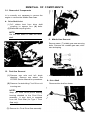
the "on" position unless the engine is operating). Disconnect fuel pipes and vacuum pipes
from petcock.
2. L i f t seat and remove fuel tank holding bolt.
Remove fuel tank.
NOTE: It is n ot necessary t o remove the engine
t o remove the cylinder head, cylinder, or pistons.
A. Preparation For Removal
1. All dirt, mud, dust and foreign material should
be thoroughly removed f ro m the exterior o f
the engine before removal and disassembly.
This will help prevent any harmful foreign
material from entering the engine.
2. Before engine removal and disassembly, be sure
that you have the proper tools and cleaning
equipment so that you can perform a clean
and efficient job.
3. During disassembly o f the engine, clean and
place all parts in trays in order o f disassembly.
This will speed assembly time and help insure
correct reinstallation o f all engine parts.
4. Place machine on center stand. Start engine
and allow it t o warm up. Stop engine and
drain engine/transmission oil.
5. Remove oil filter element t o drain oil filter.
6. If middle gear case i s t o be removed, drain
middle gear oil.
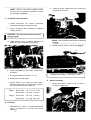
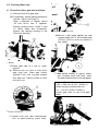
C. Muffler, Footrest, Brake Pedal
Remove rear brake pedal and passenger right
footrest.
2. Remove exhaust pipe holding screws from cylinder head.
7. Remove air scoop from cylinder head cover.
B. Fuel Tank Removal
1. Turn fuel petcocks t o "on" (there is n o "off"
position-fuel will n o t f l ow f ro m a petcock o n
3. Remove exhaust pipes and muffler as an
assembly.
D. Side Cover, Air Cleaner Case
1. Remove left and right side covers.
4.
Remove bolts holding air cleaner case to
frame. Note ground wire connection on left
frame bracket.
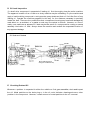
DOHC
5. Pull air cleaner case t o the rear. Remove clutch
cable from holder attached t o the left carburetor. L i f t carburetors back and to the left.
Remove throttle cable from carburetors.
2. Remove screws holding intake silencers (left
and right). Remove intake silencers.
6. Remove air cleaner case,
E. Wiring and Cables
3. Loosen clamps holding carburetors t o air cleaner case and intake manifolds. Loosen breather
hose clamp a t a i r cleaner case junction.
1. Pull back rubber cover on clutch adjustor a t
engine. Disconnect clutch cable.
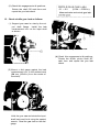
2. Remove spark plug wires and tachometer cable.
3. Remove t w o ( 2 ) screws holding starter moto r
F. Drive Shaft Joint
1. Pull rubber boot from drive shaft coupling t o
expose four (4) bolts.
cover. Remove starter moto r cover. Disconnect
electric starter cable.
2. Remove fo ur (4) bolts o n drive shaft coupling.
G . Removal
1 . Remove three ( 3) engine mounting bolts from
frame. Remove footrests w it h the t w o ( 2 ) rear
engine mounting bolts.
4. Disconnect ground wire from top o f engine
case.
5. Disconnect wiring harness couplers on left side
of machine. Remove ignition wiring (orange,
yellow, grey, blue wires), generator wiring
(white wires), and field wiring (green, black
wires). Position wires so that they can be safely removed.
2. Slide engine forward. Remove engine t o the
right. Position a box or other support to the
right of the machine for assistance when removing the engine.
3-2 ENGINE DISASSEMBLY
A. Cylinder Head and Cylinder Removal
NOTE: Cylinder head and cylinder can be removed wit hout removing engine.
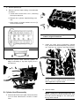
1.
Remove cylinder head cover.
2. Remove points cover. Rotate the crankshaft
t o T.D.C. o f the compression stroke o n the
NO. 1 (L.H.) cylinder. Tie each end of the cam
chain t o prevent it fr o m falling in to the crankcases when it i s separated. Push o u t the master
link pins w i t h the cam chain cutter.
5.
Remove the cam caps
CAUTION: To avoid damage to the camshaft
caps, observe the following:
a. Position cams as described in step 3.
b. The camshaft caps are numbered le ft t o
right 1, 2, 3, 4 and 'E' or 'I' fo r intake or exhaust. Damage w i ll result if the caps are incorrectly removed or installed.
c. Remove camshaft caps from right t o le ft
(4, 3, 2, 1). Notice that the arrows on the
caps all point t o th e LEFT.
d. Remove cams.
6.
Remove t w o (2) cam chain tensioner securing
bolts and remove tensioner assembly.
CAUTION : Whenever the cam chain is separated, valve and cylinder head damage can
occur by random turn ing of th e cam shafts.
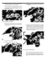
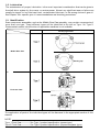
3. Rotate intake cam 1/6 turn counterclockwise
(from L.H. end) and rotate exhaust cam 1/6
turn clockwise ( f r o m L.H. end). See illustration.
7. Remove cylinder head oil pipe un ion bo lts and
remove oil pipe. No te placement o f copper
gaskets.
EXHAUST
4.
INTAKE
Remove cam chain guide stopper.
8. Remove spark plugs.
9. Remove cylinder head holding nuts and bolts
as follows:
a. Loosen each n u t and b o l t ½ t u r n , observing
the torque sequence.
b. Remove the cylinder head holding nuts
first.
c. Note location of larger washers on t w o (2)
center exhaust studs.
CAUTION: Lifters must always be installed
in their original locations.
2.
Install the valve spring compressor (special
too l). Remove the valve keepers b y using a magnet. Remove the retainer and valve springs.
CYLINDER HOLDING NUTS
10. Remove cylinder head. Remove cylinder. It
may be necessary t o tap each lightly w i t h a
soft hammer.
NOTE: The valve springs are progressively
wound. The more tig htly wou nd end is placed
down against the cylinder head.
3. Remove valves.
B. Cylinder Head Disassembly
1. Remove valve lifters and pads. Place each lifter
in a box that identifies the location o f each
lifter.
NOTE: Deburr any deformed valve stem end.
Use an o il stone t o smooth the stem end. This
will help prevent damage t o the valve guide
during valve removal.
C. Piston Removal
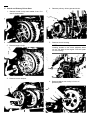
4.
1. Mark each piston t o aid in reassembly.
Remove the bolt, plate washer and lock washer
from the rotor. Use the rotor holding tool and
bolt (special tools) t o remove rotor.
2. Place a clean towel or rag into the crankcase
t o keep circlips and material from falling into
the engine.
3. Remove piston pin clips, piston pins, and
pistons.
5.
Remove the crankcase cover bolts and remove
the cover.
6. Remove oil pressure warning switch.
D. Generator
1. Remove generator wiring harness from mounting clips. Remove oil pressure warning switch
wire.
E. Bearing Housing
Remove four (4) bearing housing securing bolts and
remove bearing housing.
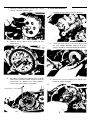
2. Remove kick crank
3.
Remove generator cover.
F. Clutch and Primary Driven Gear
4.
Remove primary driven gear and chain.
1. Remove small circlip and washer from R.H.
end of transmission.
5. Remove clutch housing.
2. Remove larger circlip.
NOTE: If the clutch plates are stuck to the
housing, thread in the clutch adjuster screw
on the left side of the engine. This will push
off the housing.
3. Remove clutch damper.
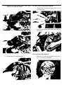
6. Remove washer and circlip in front of
pressure plate.
7.
Remove pressure plate screws and clutch
springs. Remove pressure plate.
G. Kick Gear Removal
1. Remove circlip holding the kick idlegear.
8.
Remove clutch plates, clutch push rod and
ball bearing.
2. Install the kick crank on the kick shaft. Pull
the kick starter assembly and the kick idle
gear o u t together. Remove bearing and washer.
9. Use clutch holding tool (special tool) t o hold
clutch boss. Use deep 32mm socket to remove
clutch boss nut. Remove nut, spring washer,
clutch boss, plate washer, and spacer.
3. Remove the circlip holding kick gear 4. Remove the washer and gear.
4.
Remove kick gear holder bolts. Use a slide
hammer to remove the holder.
H. Shift Lever, Shift Shaft Removal
1. Remove clip holding shift lever two (2). Remove the lever.
2.
Remove clip holding shift shaft lever. Remove
shift shaft.
I. Governor Assembly Removal
5. Remove the kick shaft assembly.
1. Remove bolt holding crankshaft turning nut
from L.H. end of crankshaft.
2. Remove neutral light wire. Remove breaker
assembly wiring harness from clamps on crankcase. Remove three (3) breaker plate holding
screws and remove breaker assembly.
3. Remove governor assembly.
4.
J.
Remove starter clutch assembly
Electric Starter Removal
Remove L.H. crankcase cover.
2. Remove idler gear 1 and shaft.
5. Remove oil delivery pipe,
3. Place a folded rag between the kick idler
gear two (2) and pump drive gear as shown.
Remove pump drive gear nut and gear. Remove cam chain.
6. Remove cam chain dampers.
Middle Gear Case Disassembly is covered in the Shaft
Drive, Section page 102.
7. Remove two (2) starter motor securing bolts.
Remove starter motor.
L. Transmission Bearing Housing Removal
Remove the transmission bearing housing bolts. Remove housing.
K. Middle Gear Removal
M. Breather Removal
Remove seven (7) middle gear case securing bolts. Remove the middle gear case, drive cam and spring.
Remove six (6) breather securing bolts. Remove
breather.
N. Oil Pump Removal and Disassembly
4.
Remove oil pump cover and rotor assembly.
1. Remove strainer cover.
5. Remove pressure relief valve: remove circlip,
washer, spring, and plunger.
6. Remove oil pump check valve: remove circlip, plug, spring, and plunger.
2. Remove oil pump.
O. Crankcase Disassembly
3. Remove oil pump driven gear.
bolt. This bolt is located near the transmission
drive axle, as shown. This bolt must be located
before proceeding with crankcase disassembly.
1. Loosen each bolt ½ turn, starting with the
unnumbered bolt. Continue by loosening the
highest numbered bolts first. The numbers of
the bolts are cast in the cases. Numbers 24~
15 are on the top case. Numbers 14-1 are on
the bottom case.
2.
Remove shift fork guide bar circlip (E-clip).
Remove guide bar.
2. Remove all crankcase holding bolts. Use a soft
rubber hammer to carefully separate the
crankcases. The crankshaft and transmission
shafts should stay in the bottom crankcase.
,
1
3. Remove main axle assembly.
4.
Remove circlip (E-clip) holding shift fork
guide two
5.
Remove guide bar, washer and both shift forks.
3. Remove crankshaft. Note location of special
main bearing ('A' bearing). This is a combination side thrust bearing and main bearing.
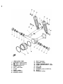
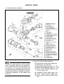
P. Transmission Disassembly
1. Remove middle driven gear.
6. Remove bolt holding middle drive gear t o
drive axle. Remove spacer.
7. Loosen transmission bearing cap nuts ½ turn.
Remove nuts and cap.
9. Remove shift cam detent and shaft cam securing bolt.
10. Remove circlip on shift cam stopper plate.
Remove stopper plate and shift cam.
8. Remove middle drive gear. Push drive axle up
a t the bearing and out so that the middle drive
gear can be removed. Remove drive axle.
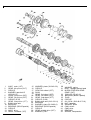
Further disassembly of the transmission shafts
can be undertaken after study of the transmission illustration.
1
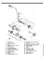
2
3
4
5
6
7
8
9
10
11
12
13
14
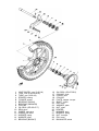
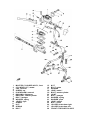
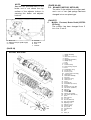
AXLE, main (13T)
GEAR, 4th pinion (21T)
CIRCLIP
WASHER, gear hold 5
(25.2-30-1 .O)
GEAR, 3rd pinion (20T)
GEAR, 5th pinion (23T)
CIRCLIP (S-25)
GEAR, 2nd pinion (17T)
SHIM, drive axle
BEAR ING
BEARING (B5205 special)
CIRCLIP
AXLE, drive
GEAR, 1st wheel (32T)
15 WASHER, plate (30.2-40-2.0)
16 CIRCLIP
17 G EA R 4th wheel (23T)
18 SHIM
19 GEAR, 3rd wheel (26T)
20 GEAR, 5th wheel (22T)
21 GEAR, 2nd wheel (27T)
22 CIRCLIP (S-30)
23 SHIM, drive axle (24.2-33-1.6)
24 BEARING
25 WASHER, plate (30.2-40-2.0)
26 BEARING (B5206 special)
27 CI RCLlP
28 GEAR, middle drive (32T)
29 WASHER, plate
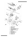
30
31
32
33
34
35
36
37
38
39
40
41
42
43
WASHER, spring
BOLT, hexagon socket head
MIDDLE DRIVEN GEAR
COMP. (34T)
COLLAR (35-40-16)
BEARING (B6207 special)
PLUG
CIRCLIP
OIL SEAL (SW-48.8-72-9)
NUT, hexagon
WASHER, plate
CAM, driven
CAM, drive
BEARING
SPRING, compression
29
1
2
3
4
5
6
7
8
9
10
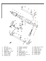
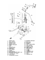
CAM, shift
PIN, dowel (4-8)
PIN, dowel (4-17.8)
BEARING
C l R C L l P ( 3 4 ø special)
PLAT E, side
SCREW, flat head
P L AT E , stopper
C l R C L l P ( S -3 0 )
STOPPER, cam
11
12
13
14
15
16
17
18
19
20
SPRING, compression
G ASKET, drain plug
SCREW
BOLT
WASHER, lock
B AR , shift fork guide 1
F O R K , shift 2
PIN, cam follower
WASHER, plate (12-22-1.0)
C l R C L l P (E-10)
21
22
23
24
25
26
27
28
29
B A R , shift fork guide 2
F OR K, shift 1
SHAF T , shift lever
SCREW, flat head
LEVER , shift 2
C l R C L l P (E-9)
SPRING, torsion
LEVER , shift 3
C l R C L l P (E-7)
3-3 INSPECTION AND REPAIR
A. Cylinder Head Cover
Intake
.020-.041mm
(.0008~.0016")
0.10 mm
(.004")
Place head cover o n a surface plate. There should be
no warpage. Correct b y re-surfacing as follows:
Exhaust
.035-.059mm
(.0014~.0023")
0.12mm
Place #400 o r #600 grit w et sandpaper o n surface
plate and re-surface head cover using a figure-eight
sanding pattern. Rotate head cover several times to
avoid removing t o o much material fr o m one side.
(.005")
2. Valve stem end
Inspect end o f valve stem. I f the end appears
t o be "mushroomed" o r has a larger diameter
than the rest of the stem, the valve, valve
guide, and oil seal should be replaced.
B. Cylinder Head
1. Remove spark plugs.
2. Remove valves.
3. Using a rounded scraper, remove carbon deposits f r o m combustion chamber. Take care
to avoid damaging spark plug threadsand valve
seats. Do n o t use a sharp instrument. Avoid
scratching the aluminum.
3. Tu r n valve o n a "V" block and measure the
amount o f stem run ou t w i t h a dial gauge. If
it exceeds the maximum limit, replace the
valve.
4. Place on a surface plate. There should be n o
warpage. Correct b y re-surfacing as follows:
Place #400 o r #600 grit we t sandpaper o n surface plate and re-surface head using a figureeight sanding pattern. Rotate head several
times t o avoid removing t o o much material
fr o m one side.
C.
Maximum Valve Stem Ru nou t:
.03mm (.0012")
4.
Valve guide and valve o il seal replacement
I f o il leaks in to the cylinder through a valve
due to a w o rn valve guide, o r i f a valve i s replaced, the valve guide should also be replaced.
Valve, Valve Guide and Valve Seat
1. Valve stem wear must be measured and then
combined w i t h valve guide measurements t o
guide clearance. This clearance must be w i t h i n
tolerances. I f it exceeds the ma x imu m limit,
then replace either o r b o th valve and guide, as
necessary .
NOTE: The valve o il seal should be replaced
whenever a valve i s removed o r replaced.
a. Measure valve guide inside diameter w i t h a
small bore gauge. I f it exceeds the limit, replace w i t h an oversize valve guide.
I
Guide diameter (I.D.): 7.01-7.02mm 7.10mm
(.276-.277") (0.280')
I
b. To ease guide removal and reinstallation, and
t o maintain the correct interference fit, heat
the head to 100°C (212°F). Use an oven to
avoid any possibility o f head warpage due t o
uneven heating.
c. Use the appropriate shouldered punch (special
to o l) t o drive the old guide o u t and drive the
new guide in.
NOTE: When a valve guide is replaced, the
o-ring should also be replaced.
d. Af te r installing t h e valve guide, use 7mm
reamer (special to o l) t o obtain the proper valve
clearance.
pits s t il l exist, then continue to c u t w i t h the
45° cutter. Remove just enough material t o
achieve a satisfactory seat.
Afte r fit tin g the valve guide i n t o th e cylinder
head, be sure to grind the valve seat, and perfo r m valve lapping. The valve must be replaced
w i t h a new one.
Seat w id th
5. Grinding the valve seat
Standard Width
Wear Limit
1.3mm
(.050")
2.0mm
(.080)
c. If the valve seat is uniform around the perimeter of the valve face, b u t i s t o o wide or not
centered o n the valve face, it must be altered.
Use either the " FLAT" , 4 5 °or 30°cutters
t o correct the improper seat location in the
manner described below:
a. The valve seat is subject to severe wear similar
t o valve face. Whenever the valve face i s resurfaced, the valve seat should also be re-sur
faced a t a 45° angle. I n addition, i f a new valve
guide has been installed ( w i t h o u t any valve repair), the valve seat should be checked to
guarantee complete sealing between the valve
face and seat.
1) I f the valve face shows that the valve seat is
centered o n th e valve face, but t o o wide,
then lig htly use both the " F L A T " and th e
30° cutters t o reduce the seat w i d t h to
1.3mm (.05").
2) If the seat shows to be in the mid dle o f t h e
valve face, but too narrow, use the 4 5 °
cutter u n t il the w i d t h equals 1.3mm (.05").
3) If the seat i s t o o narrow and rig ht u p near
the valve margin, then first use th e" F LA T"
cutter and then the 45° cutter to get the
correct seat width.
4) If the seat is too narrow and d o w n near the
bottom edge o f the valve face, then fir st use
the 30° cutter and then the 45° cutter.
CAUTION: I f th e valve seat is obviously
pitted or worn, it should be cleaned w i t h a
valve seat cutter. Use the 45° cutter, and when
twisting th e cutter, keep an even downward
pressure to prevent chatter marks.
If cuttin g section " A ' o f the intake valve seat,
use " F L A T " cutter (radius cutter). If cuttin g
section "A" o f the exhaust valve seat, use
" F L A T " cutter (also: radiused). If c ut tin g section "B", use the 4 5 °cutter.
b. Measure valve seat width. A p p ly mechanic's
bluing dye (such as Dyke m) to the valve face,
apply a very small amount of fine grinding
compound around the surface o f the valve
seat, insert the valve i n t o position, and spin the
valve q u ick ly back and forth. Li ft th e valve,
clean o f f all grinding compound, and check
valve seat width. The valve seat w i ll have removed the bluing wherever it contacted the
valve face. Measure the seat w i d t h w i t h vernier
calipers. It should measure approximately
1.3mm (.05"). Also, the se at should be un iform
in contact area. If valve seat w i d t h varies, or if
I
6. Lapping th e valve/valve seat assembly
a. The valve/valve seat assembly should be lapped
if (1) neither the seat no r the valve face are
severely worn, or (2) if th e valve face and valve
seat have been re-surfaced and now require a
final light grinding operation for perfect sealing.
measure spring free length. I f the free length
of any spring has decreased more than 2mm
(.080") from i t s specification, replace it.
b. Apply a small amount of coarse lapping compound t o valve face. Insert the valve into the
head. Rotate the va!ve until thevalveandvalve
seat are evenly polished. Clean of f the coarse
compound, then follow the same procedure
with fine compound,
Continue lapping until the valve face shows a
complete and smooth surface all the way
around. Clean of f the compound material.
Apply bluing dye to the valve face and rotate
the valve face for full seat contact which is
indicated by a shiny surface all around the
valve face where the bluing has been rubbed
away.
c. Valve leakage check
After all work has been performed on the
valve and valve seat, and all head parts have
been assembled, check for proper valve/valve
seat sealing by pouring solvent into each of
the intake ports, then the exhaust ports. There
should be no leakage past the seat. I f fluid
leaks, disassemble and continue t o lap with
fine lapping compound. Clean a ll parts thoroughly, reassemble and check again with
solvent. Repeat this procedure as often as
necessary t o obtain a satisfactory seal.
c. Another symptom of a fatigued spring is insufficient spring pressure when compressed.
This can be checked using a valve spring compression rate gauge. Test each spring individually. Place it in the gauge and compress the
spring first t o the specified compressed length
with the valve closed (all spring specifications
can be found in the previous section, Valve
Spring), then t o the length with the valve
open. Note the poundage indicated on the
scale a t each setting. Use this procedure with
the outer springs, then the inner springs.
NOTE: All valve springs must be installed with
greater pitch upward as shown.
D. Valve Spring and Lifters
1. Checking the valve springs
a. This engine uses two springs of different sizes
t o prevent valve float or surging. The chart
below shows the basic value characteristics.
0
b. Even though the spring is constructed of durable spring steel, it gradually loses some of it's
tension. This is evidenced by a gradual shortening of free length. Use a vernier caliper t o
OUTER
Free length
Installed length (valve closed)
Installed pressure
Compressed length (valve open)
Compressed pressure
Allowable tilt from vertical
39.9mm (1.571")
34.5mm (1.358")
16.27~18.73 kg (35.9~41.3 Ib)
26.0mm (1.024")
49.29~56.71 kg (108.7~125 Ib)
1.6mm (.063") or 2.5°
INNER
35.6mm (1.402")
31.5mm (1.240")
6.75~8.25 kg (14.9~18.2 Ib)
23.0mm (.908")
25.57~29.43 kg. (56.4~64.9 Ib)
2. Valve lifter
a. Check each valve lifte r for scratches or other
damage. I f the lifter i s damaged in any way,
the cylinder head surface in which it rides is
probably also damaged. I f the damage is severe,
it may be necessary to replace both the lifter
and the cylinder head.
I
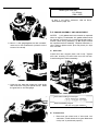
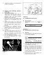
PLASTIGAUGE
CAMSHAFT
CYLINDER HEAD STUDS
FOR CAMSHAFT CAP
Cap Nut Tightening Torque:
0.8~1.0 m-kg (5.8~7.2 ft-lbs)
NOTE: Do not turn camshaft when measuring
clearance with Plastigauge.
NOTE: For proper valve lifter-to-head clearance, always install lifters on their original
valves.
E. Camshafts, Cam Chain and Cam Sprockets
1. Camshaft
Camshaft-to-cap Clearance:
Standard: .020~.054mm (.0008~.0021")
Maximum: 0.160mm (.006")
If camshaft-to-cap clearance exceeds specification, measure camshaft bearing surface diameter.
a. The cam lobe metal surface may have a blue
discoloration due t o excessive friction. The
metal surface could also start t o flake off or
become pitted.
NOTE: The exhaust cam appears darker than
the intake cam. This is due to a special hardening process and is not due to excessive
enaine heat.
b. I f any of the above wear conditions are readily
visible, the camshaft should be replaced.
c. Even though the cam lobe surface appears t o
be in satisfactory condition, the lobes should
be measured with a micrometer. Cam lobe
wear can occur without scarring the surface.
I f this wear exceeds a pre-determined amount,
valve timing and lift are affected. Replace the
camshaft if wear exceeds the limits.
d. Install the camshaft on the cylinder head.
Place a strip of Plastigauge between camshaft
and camshaft cap as illustrated (lengthwise
along camshaft). Tighten the nuts with
specified torque. Remove the camshaft cap
and determine the clearance by measuring
the width of the flattened Plastigauge.
Bearing Surface Diameter:
Standard:24.97~24.98mm (0.9830~0.9835")
1) I f camshaft diameter is less than specification, causing excessive clearance, replace
camshaft.
2) If camshaft is within specification and camshaft-to-cap clearance is excessive, replace
cylinder head.
2. Cam Chain
Except in cases of oil starvation, the cam chain
wears very little. If the cam chain has stretched
excessively and it is difficult t o keep the proper cam chain tension, the chain should be
replaced.
3. Cam Sprockets
Check cam sprockets for obvious wear. Examine damping rubber on sides of cam
sprockets. If the damping rubber is disintegrating, the sprocket should be replaced. Damaged
I
or disintegrating damping rubber will contaminate the engine oil and will lead to excessive
engine noise.
Cylinder wear should be measured a t three
depths with a cylinder bore gauge. (See illustration.)
Standard
Wear Limit
Cylinder bore
68.00~68.02mm
(2.677~2.678 in.)
68.10mm
(2.681 in.)
Cylinder taper
........
0.05mm
(0.002 in.)
Cylinder
out-of-round
........
4. Cam Chain Dampers
Inspect the top cam chain damper (stopper
guide) and two (2) vertical (slipper-type)
dampers for excessive wear. Any that shows
excessive wear should be replaced. Worn
dampers may indicate an improperly adjusted
or worn-out cam chain.
0.05mm
(0.002 in.)
If the cylinder wall is worn more than wear limit, it
should be rebored.
G. Piston And Piston Rings
1. Piston
a. Measure the outside diameter of t he piston a t
the piston skirt.
Measurement should be made a t a point l0mm
in.) above the bottom edge of the piston.
Place the micrometer a t right angles t o the
piston pin.
F. Cylinder
1. Inspect the cylinder walls for scratches. I f
vertical scratches are evident, the cylinder
wall should be rebored or the cylinder should
be replaced.
2. Measure cylinder wall wear as shown. I f wear
is excessive, compression pressure will decrease. Rebore the cylinder wall and replace
the piston and piston rings.
The color mark is painted on the expander
spacer.
Standard
Oversize 1
Oversize 2
67.96mm
67.97m m
68.25mm
68.50mm
Oversize 3
68.75mm
Size
Oversize 1
Oversize 2
Oversize 3
Oversize 4
Color
Brown
Black
Yellow
c. Push the ring into the bore and check end gap
clearance with a feeler gauge.
b. Determine piston clearance as follows:
Minimum bore measurement
- Maximum Diston measurement
= Piston clearance
I
NOTE: The end gap on the expander spacer
of the oil control ring is unmeasureable. I f the
oil control ring rails show excessive gap, a ll
three components should be replaced.
Top/2nd ring
EXAMPLE:
68.02mm
- 67.97mm
=
.05mm piston clearance
c. Piston ring/ring groove fit must have correct
clearance. If the piston and ring have already
been used, the ring must be removed and the
ring groove cleaned of carbon. The ring should
then be reinstalled. Use a feeler gauge to measure the gap between the ring and the land.
Side clearance
0.04-0.08mm
(0.0016-0.003 in.)
0.03-0.07mm
(0.0012-0.0028 in .)
Oil control
(Rails)
0.2~0.4mm
(.008~.016 in.)
0.2~0.9mm
0.80mm
(0.03 in.)
Visual
H. Piston Pin
1. Apply a light film of oil to pin. Install in connecting rod small end. Check for play. There
should be no noticeable vertical play. If play
exists, check connecting rod small end for
wear. Replace pin and connecting rod as required.
2. The piston pin should have no noticeable free
play in piston. If the piston pin is loose, replace the pin andlor the piston.
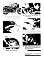
I. Crankshaft
1. Crankshaft Run-Out
Support the crankshaft a t both ends on
V-blocks. Measure the amount of crankshaft
run-out on the main bearing journals with a
dial gauge while rotating crankshaft.
2. Piston Ring
a. The oversize top and middle ring sizes are
stamped on top of the ring.
Oversize 2
Oversize 3
Oversize 4
0.50mm
0.75mm
1.00mm
b. The expander spacer of the bottom ring (oil
control ring) is color-coded t o identify sizes.
I
Run-out limit: .03mm (.001 in.)
I
If run-out exceeds limit, replace crank.
2. Inspection Of Inserts
LEFT CENTER
Check the bearing inserts. If the inner orouter
surface is burned, flaked, rough, scratched or
worn, the insert should be replaced.
3. Measuring Main Bearing Oil Clearance
a. Clean all crankshaft and crankcase journal
surfaces.
b. Each main bearing journal is numbered 1, 2
or 3. Each crankcase bearing housing is numbered 4, 5 or 6. The proper insert selection is
made by subtracting the crankcase number
from the crankshaft journal number. The
result is the insert size (number).
b. Place upper crankcase half upside-down on a
bench. Install bearing inserts into top crankcase.
c. Install crankshaft into upper crankcase.
d. Place Plastigauge on crankshaft journal surface
t o be inspected.
NOTE: Do not move crankshaft until clearance check has been completed.
e. Install bearings inserts into bottom crankcase.
Carefully, place lower crankcase onto upper
crankcase.
f. Install crankcase holding bolts 1 through 10.
Tighten to full torque in torque sequence
cast on crankcase.
g. Remove bolts in reverse assembly order
(10,9,8.. . . .etc.)
h. Carefully remove lower crankcase. Measure
width of Plastigauge on crankshaft journals to
determine clearance.
I
TOP CRANKCASE
Use the color code table to choose the proper insert.
INSERT COLOR CODE
Main bearing oil clearance:
.022~.044mm
(.0008~.0017 in.)
4. Crankshaft Main Bearing Selection
a. Numbers used to indicate crankshaft journal
sizes are stamped on the L.H. crank web. The
first four (4) are main bearingjournal numbers,
starting with the left journal and proceding to
left center, right center, and right. The three
(3) rod bearing journal numbers follow in
the same sequence.
No. 1
Blue
No. 2
No. 3
No. 4
No. 5
Black
Brown
Green
Yellow
EXAMPLE:
Case No. (Minus) Journal No. = Insert No.
4
-
2
No. 2 insert is Black. U s e a black main bearing
insert.
NOTE: There is a special thrust bearing
(insert) located in the No. 3 main bearing
housing in the upper crankcase. The function
of this insert is t o provide a bearing surface
for crankshaft side thrust.
c. When assembling, apply a liberal coat of
motor oil t o all bearing surfaces.
d. Observe normal
torque sequence.
J.
crankcase
holding
bolt
Connecting Rod
1.
c. Remove connecting rod and cap. Measure
width of Plastigauget o determine oil clearance.
I
Oil clearance (rod):
.032~.054mm (.001~.002 in.)
I
I
I
d. Remove Plastigauge from bearing surfaces.
4. Selecting Rod Bearing Inserts
a. Connecting rod size numbers are indicated by
4. 5 or 6 and are marked in ink on the connecting rods and caps.
Remove rod cap securing nuts, rod cap and
inserts.
2. Inspection
a. Examine bearing inserts for scratches, flaking
or other obvious signs of wear or damage. If
the inner or outer surfaces are worn or damaged, the inserts should be replaced.
b. Examine the connecting rods and crankshaft.
3. Measure Rod Bearing Clearance
Measurement o f rod bearing clearance is
similar to main bearingclearance measurement.
a. Clean a ll bearing surfaces.
b. The rod bearing journal size numbers are indicated by 1, 2 or 3 and are stamped on the left
end of the crankshaft,
b. Place a piece of Plastigauge on connecting rod
cap. Place cap on crankshaft journal. Do not
allow the cap t o move. Install special bolts and
apply molybdenum
grease t o the
threads. Install rod cap and nuts. Tighten rod
caps evenly t o specified torque:
c. The proper insert selection is made by subtracting the rod size number from the crankshaft journal number. Use the color code t o
choose the proper insert.
Rod No. (Minus)
5
Rod cap torque: 3.8 kg-m (27 ft-lbs)
-
Journal No. = Insert No.
2
=
3
No. 3 insert is Brown. Use brown bearing inserts.
EXAMPLE:
INSERT COLOR CODE
No. 1
No. 2
Blue
Black
No. 3
Brown
No. 4
Green
No. 5
Yellow
a conventional motorcycle drive chain. The
plates of the chain form a mating surface for
the primary gear teeth. That is, the primary
gears actually mesh with the chain plates. This
chain is extremely durable and, under normal
conditions, can be expected t o last the li fe
of the motorcycle engine. However, if obvious
damage is caused through serious oil starvation or abrasive oil contamination, the chain
should be replaced.
2. Clutch Damper
d. When assembling, apply a liberal coat of motor
oil t o al l bearing surfaces.
NOTE: When applying final torque to the rod
caos. Observe the following procedures:
Apply molybdenum disulfide grease t o connecting rod bolt threads. Apply torque evenly
to both ends of the cap. While tightening, if
a torque of 3.3 m-kg (24 ft-lbs) or more is
reached, DO NOT STOP tightening until
final torque is reached. If tightening is interrupted between 3.3 m-kg and 3.8 m-kg,
loosen the nut t o less than 3.3 m-kg and sta rt
again. Tighten t o full torque specification
without pausing.
a Remove circlip using a press and special tool.
Press tool on collar no more than necessary t o
remove circlip. Damper springs may be damaged if excessive pressure is applied.
b. Inspect damper cam and pin surfaces. Check
for smooth cam action (as illustrated by
arrows). Check for excessive wear on cam and
pin surfaces. If operation is not smooth or cam
surfaces are severely worn, replace damper
assembly.
K. OIL PUMP
1. Check the clearance between housing and
outer rotor.
Standard clearance:
0.09~0.015mm
(0.0035~0.0059 in.)
2. Check the clearance between outer rotor and
inner rotor.
Standard clearance:
0.03~0.09mm
(0.0011~0.0035 in.)
3. Remove the relief valve and check valve plungers from oil pump assembly. Check the
plungers for scratches and wear.
L. PRIMARY DRIVE
1. "Hy-Vo" Chain And Primary Gears
The "Hy-Vo" primary chain is a plate-and-pin
type that does not use rollers as in the case of
c. Inspect plate washer and thrust bearing for
wear or damage. Replace as necessary.
NOTE: Galling on clutch plate splines will
cause erratic clutch operation.
5.
Friction and Clutch Plates
Check clutch steel plates and friction plates
for heat damage. Measure friction plate thickness at 3 or 4 points. Measure clutch plates
for warpage with a dial gauge and stand. Replace clutch plate or friction plates as a set if
any is faulty or beyond wear limits.
d. Damper Reassembly
1) Install thin plate washer, thrust bearing and
thick plate washer in that order.
I
Friction plate
thickness
Clutch plate
warp limit
I
Standard
Wear Limit
3.0mm
(0.12 in.)
2.8mm
(0.11 in.)
0.05mm
(0.002 in.)
I
2)Install damper springs.
6. Clutch Push Rod
3) Install collar.
4) Use press and special tool t o install circlip.
CAUTION:
When installing circlip,
damper pin must be positioned in
center of the damper cam. Damage t o
damper assembly could result from
proper positioning.
the
the
the
im-
3. Clutch Housing
a. Check dogs on clutch housing. Look for cracks
and signs of galling on edges. If damage is
moderate, deburr. If severe, replace clutch
Check ends of clutch push rod for indentation. If severe, clutch adjustment may be difficult. Check for loosenessof the steel ends of
the push rod. I f ends are loose or indented,
replace push rod.
7. Clutch Springs
Measure clutch spring free length. Replace
springs as a set i f any is less than minimum
free length.
Clutch spring minimum length:
4.15mm (1.63 in.)
housing.
NOTE: Galling on the friction plate dogs of
the clutch housing will cause erratic clutch
operation.
b. Apply a thin film of oil t o transmission main
shaft and inside surface of clutch housing. Slip
clutch housing over main shaft.
M. Transmission
1. Inspect each shift fork for signs of galling on
gear contact surfaces. Check for bending. Make
sure each fork slides freely on i t s guide bar.
2. Roll the guide bars across a surface plate. I f
any bar is bent, replace.
4. Clutch Boss
3. Check the shift cam grooves for signs of wear
b. The clutch boss contains a built-in damper beneath the first clutch plate (clutch plate 2). lt
is not normally necessary to remove thecirclip
and disassemble the built-in damper unless
there is serious clutch chattering.
b. Check splines on clutch boss for galling. I f
damage is slight t o moderate, deburr. I f it is
severe, replace clutch boss.
or damage. I f any profile has excessive wear
and/or damage, replace cam.
4. Check the cam followers on each shift fork for
wear. The follower should fit snugly into i t s
seat in the shift fork, but should not be overly
tight. Check the ends that ride in the grooves
in the shift cam. I f they are worn or damaged,
replace followers.
b. Kick Clip Spring
5. Check shift cam dowel pins and side plate for
looseness, damage or wear. Replace as required.
1) The kick clip is fitted to kick gear (5) and
slides i n the groove. A too-tight or loosefitting clip may result in improper operation.
I f too loose, bend the kick clip so that
the friction increases, or replace clip.
6. Check the shift cam stopper plate and circlip
and stopper for wear. Replace as required.
7. Check the transmission shafts using acentering
device and dial gauge. I f any shaft is bent beyond specified limit, replace shaft.
Maximum run-out:
.03mm (.001")
O. Crankcases and Strainer Cover
1. Check crankcases for cracks or other damage.
8. Carefully inspect each gear. Look for signs of
obvious heat damage (blue discoloration).
Check the gear teeth for signs of pitting,
galling or other extreme wear. Replace as
required.
2. Clean all oil passages and blow out with compressed air.
3. Strainer cover: Apply Loctite to strainer cover
bolts during reassembly.
9. Check to see that each gear moves freely on
i t s shaft.
10. Check to see that all washers and clips are
properly installed and undamaged. Replace
bent or loose clips and bent washers.
11. Check to see that each gear properly engages
i t s counterpart on the shaft. Check the mating
dogs for rounded edges, cracks, or missing
portions. Replace as required.
N. Starter Drives
P.
Bearings and Oil Seals
1. After cleaning and lubricating bearings, rotate
inner race with a finger. I f rough spots are felt,
replace the bearing.
NOTE: Bearings are most easily removed or
installed if the housings are first heated to
approximately 95°~ 125°C (200°~250°F).
Bring the case up t o proper temperature
slowly. Use an oven t o avoid distortion.
1. Electric Starter Clutch And Gears
a. Check pin contact surface of idle gear (2) for
pitting or other damage. I f severe, replacegear.
2. Check oil seal lips for damage and wear.
Replace as required.
b. Check spring caps and springs for deformation
or damage. I f severe, replace as necessary.
Q. Middle Gear Case
c. Check starter clutch bolt (allen screw) for
looseness. I f loose, remove bolt and replace
with new bolt. Apply Loctite t o threads and
tighten to specified torque. Stake over end of
bolts in oil pump driven gear (1).
NOTE: This section involves external inspection
only. For middle gear case overhaul and adjustment, refer to the Shaft Drive Section page 102.
Starter clutch bolt torque:
2.8~3.2 m-kg (20~23 ft-lbs)
2. Kick Starter
a. Kick Gears
1) Check the kick gears for wear or scratches
on teeth, particularly in the chamfered area
of each gear.
1. Inspect entire exterior for leakage. If leakage
is found, the unit should be disassembled.
2. Check middle gear lash as follows:
a. Support gear case in a vise by the output
shaft flange. Connect the lash measurement
tool to the input shaft as shown.
Middle gear case lash:
0.1~0.2mm
(.004~.008")
If lash is not within tolerance, refer to Drive
Shaft Section page 102
3-4 ENGINE ASSEMBLY AND ADJUSTMENT
b. Mount a dial gauge against the lash measurement tool a t the scribed mark (34mm from the
center of the shaft).
NOTES: 1) All gaskets and seals should be replaced
when an engine is overhauled. All gasket surfaces must
be cleaned. 2) Properly oil all mating engineand transmission parts during assembly. 3) All circlips should
be inspected before assembly. Replace distorted circlips. Always replace cotter pins and piston pin clips
after one use.
A. Shift Cam
Install shift cam, stopper plate, and circlip. Tighten
shift cam locating bolt and bend over the lock tab.
Install and tighten detent assembly.
c. Hold the gear case and rotate the input shaft
back and forth using the special wrench. Read
the gear lash on the dial gauge.
Shift cam locating bolt torque:
1.3~2.1m-kg (9-15ft-lbs)
Detent assembly torque:
4.0~4.5 m-kg (29~32ft-lbs
B. Transmission
1. Place 2nd gear wheel end of drive axle into
crankcase. Install middle drive gear. Make sure
circlip half is positioned properly.
5. Install main shaft and clutch push rod seal.
2. Install bearing cap, washers, dnd nuts. Tighten
bearing cap.
Bearing cap torque:
1.8~2.2 m-kg (13~16 ft-lbs)
3. Install plate washer, spring washer, and bolt
6.
Install shift fork guide bar and shift fork 1.
Install circlips (E-clips).
7. Install middle driven gear. Make sure circlip
halves are properly installed. Each circlip half
f i t s into both crankcases.
ClRCLlP
HA LF
holding drive axle.
4. Place shift fork guide bar into crankcase. Place
plate washer and shift forks on the guide bar.
The washer must be positioned next to the
bearing cap. Install the circlip (E-clip) on the
shaft to hold the plate washer next to the
bearing cap.
M ID DL E
NOTE: When installing shift forks, make sure
cam follower pins are correctly positioned in
the shift cam.
GEAR BEARING
2.
NOTE: When a new seal is installed, grease
the lips of the seal before installation. Inspect
the seal after installation.
Install oil pump. Make sure rotor housing seal
is positioned correctly.
C. Crankshaft and Crankcases
1. Install crankshaft into bottom crankcase.
Crankcase bearings must be well oiled.
2. Apply Yamabond No. 4 sealant to crankcase
mating surfaces.
CAUTION: DO not allow sealant t o contact
bearing inserts.
I
NOTE: The oil pump must be full of oil when
installed.
3. Make sure the o-ring is installed. Make sure a ll
shafts and seals are positioned properly.
3. Install strainer cover. Use a new gasket.
4.
Install crankcase top and bolts. Install bolts
as follows:
a. Use copper washers on bolts 5, 6, 7, 8.
b. Bolt threads must be oiled.
c. Tighten bolts in two stages in proper torque
sequence. Start with bolt number one. Tighten
the unnumbered bolt as number 24.
Stage 1: 8mm bolts 1 . 0 m - k g (7 ft-lb)
10mm bolts
2.0 m-kg (14 ft-lb)
Stage 2: 8mm bolts
2.0 m-kg (14 ft-lb)
10mm bolts
3.7 m-kg (27 ft-lb)
D. Oil Pump
1. Reassemble oil pump in reverse disassembly
order. Lubricate the oil pump well during
assemb Iy .
I
Strainer cover torque: 1.0 m-kg (7 ft-lb)
I
E. Shifter Assembly
1. Install shift shaft. Install circlip (E-clip) on
left side of crankcases.
1
CRANK, kick
2 COVER, kick lever
3 BOSS, kick crank
4 BOLT
5 WASHER, plate (15.5-24-1.5)
6 CIRCLIP (E-10)
7 B A L L (7/32 inch)
8 SPRING, compression
9 01L SEAL (SD-20-30-7)
10 WASHER, plate (20.2-30-1.0)
11 ClRCLlP (S-20)
12 COVER, kick spring
13 SPACER
14 SPRING, torsion
15 KIC K S H A FT ASS'Y (22T)
16
17
18
19
20
21
22
23
24
25
26
27
28
29
SHIM, kick shaft 1 (40.3-54-0.8)
BEARING
KICK ID L E GEAR ASS'Y (38/30T)
SHIM, kick shaft 2 (35.3-54-0.8)
CIRCLIP (S-35)
CIRCLIP (S-17)
SH IM
GEAR, kick 4 (20T)
HOLDER, kick gear
PIN, dowel (4-10)
BOLT, hexagon socket head
CLIP, special
GEAR, kick 5 (21T)
SH AFT, kick 2
1
2
3
4
5
6
7
8
9
10
11
12
13
14
DAMPER ASS'Y
CIRCLIP
WASHER, plate (76-95-0.8)
BEARING
WASHER, plate (69-95-5.4)
SPRING, damper
COLLAR
CIRCLIP
CLUTCH ASS'Y
CLUTCH HOUSING COMP.
SCREW
SPRl NG, compression
PLATE, pressure
PLATE, friction 1
15 PLATE, clutch 1
16 CLUTCH BOSS ASS'Y
17 PLATE, seat
18 SPRING, clutch boss
19 PLATE, clutch 2
20 CIRCLIP
21 CIRCLIP (S-20)
22 WASHER, plate (21.2-29-2)
23 CIRCLIP
24 GEAR, primary driven (45T)
25 WASHER, plate (22-36-2.6)
26 ROD, push 1
27 NUT, hexagon
28 WASHER, conical spring
29 WASHER, plate (25.2-39-1.0)
30 SPACER
31 B A L L (5/16 inch)
32 ROD, push
33 OIL SEAL (SD-8-25-8)
34 BALL SCREW ASS'Y
35 SCREW, adjusting
36 NUT, adjusting
37 SPRING, torsion
38 HOOK, spring
39 SCREW, pan head
40 JOINT
41 PIN
42 PIN, cotter
2. Install shift lever 2. The dot on shift lever 2
must align with the dot on the shaft.
4.
Install shim and bearing onto idler shaft. Oil
the bearing.
3. Shift transmission into second gear. The line
on the shift cam must align with the line on
shift lever 2. I f not aligned, adjust by turning
the adjusting screw.
F. Kick Starter Assembly
1. Install kick gear 5 assembly into crankcases.
The kick clip (special clip) must be positioned
in the groove.
2.
Install kick gear holder.
3.
Install kick gear 4, shim, and circlip.
5. Install the kick starter shaft and kick idle gear
assembly together. Use the kick crank to help
install the kick shaft assembly. Install the
torsion spring on the boss. Install the washer
and circlip on the kick shaft. Check the movement of the kick shaft with the kick crank.
Remove the kick crank.
G. Clutch and Primary Drive
1. Install clutch spacer, plate washer, and clutch
boss. Install the spring washer and lock nut.
Use the clutch holding tool and special 32mm
deep socket (special tool) to tighten the clutch
nut.
Clutch nut torque:
8m-kg (58 ft-lbs)
I
next dot on the clutch boss. Follow this pattern clockwise around the clutch boss until
al l friction and steel clutch plates are installed.
3. Install push rod 1 intotheslot in the main axle.
4.
2.
Install plate washer onto main axle. Install
pressure plate with the arrows matching the
arrows on the clutch boss.
Install a clutch friction plate, then a steel
clutch plate. Install clutch friction plates and
steel plates alternately.
5. Install two clutch springs and screws lightly
so that the clutch plates can be moved.
6. Install the clutch alignment tool (special
tool) t o align the clutch friction plates. The
tool must be centered on the clutch pressure
plate.
7. Install remaining clutch springs and screws.
Tighten all clutch screws. Remove clutch alignment tool. Install circlip. Install plate washer.
NOTE: Each steel clutch plate has a tab. There
is a dot on the clutch boss t o correspond t o
each tab. Install a clutch plate tab next t o one
dot. Position the next steel plate next t o the
Clutch screw torque:
0.8~1.0 m-kg (6~7 ft-lbs)
.^
8. Carefully install spacer and clutch housing. Use
care t o avoid damaging friction plates.
9. Place drive chain on drive gear. Install damper
assembly into primary driven gear and install
this assembly into the clutch assembly.
I
Rotor bolt torque:
3.0~4.0 m-kg (22~29 ft-lbs)
4. Install generator assembly. Connect oil pressure warning wire to the switch. Install all
generator cover and right crankcase cover
screws. Route the wiring harness and install
generator cover screw with wire harness clamp.
5.
Install breather cover.
J. Middle Gear
1. Install drive cam and spring onto middlegear
shaft.
10. Install plate washer and circlip on main axle.
Install large circlip on clutch damper.
H. Bearing Housing
Install bearing housing. Tighten bearing housing bolts.
Bearing housing bolt torque:
2.0~2.4 m-kg (14~17 ft-lbs)
I. Right Crankcase Cover
1. Install oil pressure sending switch.
2. Install a new gasket and install middle gear case.
2. Place plate washer on kick shaft. Install a new
gasket and the right crankcase cover. Do not
use all cover screws until rotor and generator
cover are installed.
3.
Install rotor, plate washer, spring washer and
bolt. Hold rotor with special rotor holding
tool and tighten bolt.
I
Middle gear case bolt torque:
2.0-2.5 m-kg (14-18 ft-lbs)
I
K. Drive Axle Bearing Housing
1. Oil drive axle bearing.
2. Install drive axle shim on drive axle.
3. Oil the o-ring on the bearing housing. Install
bearing housing. Attach wire harness clamp to
lower securing screw.
3. Install cam chain dampers. Install the damper
with the three (3) raised blocks t o the front.
4.
Install cam chain onto drive sprocket. Connect
wire t o each end of cam chain.
5. Install oil pump drive gear. Place a rag between
oil pump drive gear and driven gear t o lock the
gears. Install plate washer and nut. Tighten nut.
L. Left Crankcase Cover
1. Oil Delivery Pipe
Oil the threads of the oil delivery pipe union
bolts. Install new washers on each side of each
bolt and tighten bolts.
gear nut torque:
8.0~12.0 m-kg (58~87 ft-lbs)
Oil delivery pipe torque:
2.0~2.2 m-kg (14~16 ft-lbs
2.
Install plate washer on oil pump driven gear
shaft. Install starter clutch assembly.
I
6. Install starter motor
7. Install starter motor idler gear and kick idler
gear. Install the idler gear shaft.
I
Crankshaft turning nut (bolt) torque:
1.5~2.9 m-kg (11~21 ft-lb)
8 . Install clutch ball bearing and clutch push rod.
N. Pistons and Cylinder
1. Install pistons on rods. The arrow on the pistons must point to the front of the engine.
NOTE: Always install new piston pin circlips.
2.
Install a new cylinder base gasket. Install new
cylinder seal 2, with f l a t side into crankcase.
Install three cylinder base o-rings.
9. Install plate washer on starter clutch shaft.
Install left crankcase cover.
NOTE: Install two wiring harness clamps on
lower cover screws.
M. Ignition Assembly
1. Install governor assembly.
2.
Install contact breaker plate assembly. Route
the assembly wires using the clamps provided.
3. Attach neutral light wire.
4. Install crankshaft turning nut on crankshaft.
Tighten securing bolt.
3. Install two round cylinder seals (cylinder seal
3). The flat side of the seal is the top and f i t s
into the cylinder.
CYLINDER HEAD
CYLINDER SEAL 3
CYLINDER
CRANKCASE
4. Position piston rings as shown.
TOP
Stage 1 :
l0mm nut (No.1-8): 1.5 m-kg ( 1 1 ft-lbs)
8mm bolt (No. 9, 10): 1 m-kg (7 ft-lbs)
OIL RING
(LOWER RAIL)
Stage 2:
10mm nut (No. 1-8):
3.5 m-kg (25 ft-lbs)
8mm bolt (No. 9,10):2.0 m-kg (14ft-lbs)
5.
OIL RING
(UPPER RAIL)
Install two (2) cylinder head holding nuts
with washers on left side of cylinder.
2ND
NOTE: Make sure ends of oil ring expanders
are not overlapped.
O. Cylinder Head Installation
NOTE: The assembly of the cylinder head is the
reverse of the disassembly procedure. Install valve
springs with tighter windings (smaller pitch) down.
Install each valve lift er in i t s original location.
a
1. Install new cylinder head gasket. Place thegasket with the tab forward. Install a new cylinder seal 1.
2. Install two new cylinder seals (cylinder seal 3)
with the rounded side into the cylinder.
3. Install cylinder head. Place two (2)thicker
plate washers on two (2)center exhaust studs.
Install remaining washers and nuts.
4. Tighten ten (10)top cylinder head nuts and
bolts. Oil the threads before tightening. Tighten in two (2)stages of one-half torque each.
Tighten according t o the proper sequence
(No. 1, 2, 3, etc.)
CYLINDER HOLDING NUTS
I
Holding Nuts Torque: 2.0 m-kg (14 ft-lbs)
6. Install oil delivery pipe. Use a copper washer
on each side of each end of the pipe. Install
the shorter union bolt into the crankcase.
P.
Camshaft Installation
1. Position cylinder No. 1 (l e f t ) a t T.D.C.
2. Oil the exhaust cam bearing surfaces. Oil the
cam caps. Install the exhaust cam and caps.
The dot on the cam must align with the arrow
on the No. 1 cap. The caps are numbered from
left t o right: 1, 2, 3,4. The arrows on the caps
point t o the left.
CYLINDER HEAD TO RQ UE SEQUENCE
3. Place washers and nuts on cam shaft cap studs.
NOTE:
Manufacturer's marks or numbers
stamped on the rings are on the top side of the
rings. Coat pistons and rings well with oil.
5.
Install the cylinder. A ring compressor is
usually not necessary.
CAUTION: Do not turn camshaft except as
noted in Step 4. Damage to valves could result.
2. Place cam chain on cam sprockets. The dots on
the cams must be aligned with the arrows on
the No. 1 cam caps. The No. 1 cylinder must
be a t T.D.C. (The No. 1 "T" mark on the governor aligned with the stationary timing mark.)
3. Install a new cam chain tensioner. Remove
the tensioner cover. Loosen the adjuster bolt.
Turn the crankshaft until the cam chain tensioner rod moves t o i t s inner most position.
Tighten the adjuster bolt and lock nut. Install
tensioner cover.
4. Turn exhaust cam only 1/6 turn (one flat)
clockwise, and back to arrow-to-dot alignment.
This will help seat the camshaft on the bearing
surfaces. Gradually tighten caps from left t o
right. No 1 4 in that order.
-
1/6TURN ONLY
EXHAUST
I
INTAKE
Camshaft Cap Torque: 1 m-kg (7 ft-lbs)
5.
I
I
Install intake cam using procedures 1-4. Turn
intake cam 1/6 turn counterclockwise.
R. Cylinder Head Cover
1. Install new cylinder head cover gasket. Install
cylinder head cover.
2.
Install air scoop brackets.
Q. Cam Chain Installation
1. Install guide stopper
3-5 REMOUNTING ENGINE
See page 106 sections 3-6 timing plate setting.
A. Remounting Engine
1. Refer to Chapter 3-1 for engine removal. Reverse the applicable removal steps.
2.
Install and tighten engine mounting bolts.
Engine mounting bolt torque:
l0mm bolt: 5.0~6.0 m-kg (36~43 ft-lbs)
12mm bolt: 8.0~11.O m-kq (58~80 ft-lbs)
3.
Install oil filter. Remove oil filter filler bolt.
Fill oil filter with 0.5 lit (0.5 qt.) engine oil.
ADD OI L H E R
CAUTION: The filter must be filled with the
specified amount of oil t o prime the oil pump
of an overhauled engine.
4. Tighten engine oil drain plug, oil filter mounting bolt, and middle drain plug.
Torque:
Engine oil drain plug:
3.9~4.7 m-kg (28~34 ft-lbs)
Oil filter mounting bolt:
3.0~3.4 m-kg (22~25 ft-lbs)
Middle gear drain plug:
3.9~4.7 m-ka (28~34 ft-lbs)
5. Add oil to engine and middle gear case
Engine oil: 3.0 lit (3.2 US qt.)
Middle gear oil: 360cc (12 oz)
I
NOTE: These oil quantities are for an overhauled engine. Observe oil filter filling procedure.
CAUTION: If oil pressure warning light (red
light) stays on after starting engine, stop engine
immediately. Fill oil filter with oil as in step 3
above. Check for proper operation of the
warning light.
NOTE: See sections 3-6 on page 106 Timing plate setting.
1
2
3
4
5
6
7
8
9
10
11
12
13
14
15
16
17
18
19
20
21
22
23
24
25
26
27
28
29
30
31
32
33
34
35
36
37
38
39
40
41
42
43
44
45
CARBURETOR ASS'Y
CARBURETOR ASS'Y 1
CARBURETOR ASS'Y 2
CARBURETOR ASS'Y 3
NOZZLE, main (Y- 2)
O-RING
V AL V E SEAT ASS'Y (2.0 ø)
WASHER, valve seat
NET, filter
F LO AT
PIN, float
GASKET, float chamber
BODY, float chamber
JET, pi lot (No. 17.5)
SCREW, pan head
WASHER, spring
JET, main
WASHER
SCREW, plug
DIAPHRAGM ASS'Y
NEEDLE (4H11-3)
CLIP, needle
PLATE, needle fitting
SPRl NG, diaphragm
COVER, diaphragm
SCREW, pan head
WASHER, spring
GASKET, starter body
BODY, starter
PLUNGER, starter
SPRING, plunger
WASHER
CAP, plunger
COVER, plunger cap
BUSHING, starter plunger
CLIP
RING
WASHER
LEVER, starter 1
WASHER
SPRING, starter lever
WASHER, spring
SCREW, pan head
SPRING, pilot screw
SCREW, pilot
I
46
47
48
49
50
51
52
53
54
55
56
57
58
59
60
CAP, pi lot screw
NUT
WASHER
COLLAR, spring
LEVER, throttl e
SPRING, throttl e
S EAL ( 8 ø )
SCREW, throttl e stop
SPRING, throttl e stop
ROD, push
SPRING, adjuster
CLIP
BRACKET
SCREW, pan head
WASHER, spring
61
62
63
64
65
66
67
68
69
70
71
72
73
74
75
BUSHING
ADJUSTER
SCREW, pan head
NIPPLE
THROT TLE BRACKET ASS'Y
PLATE, upper
PLATE, lower
WASHER, spring
SCREW, pan head
LEVER, starter 2
SCREW
PIPE, starter lever shaft
SPRING, starter lever shaft
SHAFT, starter lever
CLIP
CAR B U R ETION
4-1 CARBURETOR
A. Description
The XS750D is equipped with three "constant velocity" (C V) carburetors mounted on rubber intake manifolds.
Air flow through the venturi is controlled by a throttle slide (vacuum piston). The slide is raised and lowered by
engine vacuum rather than a cable linked directly t o the throttle grip. This type of carburetor Compensates automatically for atmospheric pressure changes such as those encountered when riding t o high altitudes.
B. Specifications
Main j et
Jet needle
Needle jet
Starter jet
Float height
Pilot jet
Low speed screw
Fuel valve seat
3. Remove vacuum chamber cover. Remove the
spring, needle fitting plate, needle, and diaphragm (vacuum piston).
#145
4H11-3
Y-2
#45
26.6mm (abovegasket
surface)
#17.5
preset
2.0mm
4. Note that there are tabs on the rubber diaphragm. There are matching recesses in the
carburetor body for the diaphragm tabs.
T
NOTE: The low speed mixture screw settings are
adjusted at the factory with the use of specialized
equipment. Do not attempt t o change these settings.
C. Disassembly
1. Prepare t o separate carburetors (separation not
necessary if only float level adjustment or
throttle slide inspection i s to be done). Remove starter lever ( 1). Loosen starter lever (2)
securing screws and remove starter lever rod.
2.
Remove upper and lower brackets. Note position of synchronizing screws for guidance in
reassembly. Separate carburetors.
5. To inspect starter jet, remove three (3)screws
holding the starter body t o the left side of the
carburetor.
6. Remove the four (4) screws holding the float
bowl cover.Remove float bowl cover. The main
jet is located under a cover in the float bowl.
3.
7. Pull out float pivot pin. Remove the float as-
4. Inspect vacuum piston and rubber diaphragm.
If the piston i s scratched or the diaphragm i s
torn, the assembly must be replaced.
sembly. Be careful t o not lose the float valve
needle located under the float level adjustment
tang. Remove the needle jet.
Inspect inlet needle valve and seat for wear or
contamination. Replace these components as
a set.
FLOAT LEVEL PIN
8. Reassemble in reverse order. Pay close attention t o the installation of the vacuum piston
diaphragm.
E. Adjustments
D. Inspection
1. Float level adjustment
1. Examine carburetor body and fuel passages. If
contaminated, wash carburetor in petroleumbased solvent. Do not use caustic carburetor
cleaning solutions. Blow out all passages and
jets with compressed air.
2. Examine condition of floats. If floats are
leaking or damaged, they should be replaced.
Measure the distance from the bottom of the
float t o the float bowl gasket surface.Bendthe
tang on the float arm if any float level adjustment is necessary. Both floats must be a t the
same height. I f the fuel level is too high, a rich
air/fuel mixture will occur. I f too low, a lean
mixture will result.
TANG
2. Jet needle adjustment
The mid-range air/fuel supply is affected by
the position of the needle i n the needle jet. If
it is necessary to alter the mid-range air/fuel
mixture characteristics of the machine, the jet
needle position may be changed. Move the jet
needle up for a leaner condition or toward the
bottom position for a richer condition.
I
Jet needle
C. Front Wheel Inspection
CHASSIS
1. Check for cracks, bends or warpage of wheels.
If a wheel is deformed or cracked, it must be
replaced.
5-1 FRONT WHEEL
A. Removal
2. Check wheel run-out. I f deflection exceeds
tolerance, check wheel bearing or replace
wheel as required.
1. Remove cotter pin from front axle nut.
2. Remove the front axle nut.
3. Loosen the two axle nut holder nuts a t the
bottom of the fork leg.
4.
Raise the front wheel of the machine by
placing suitable stand under the engine.
5. Remove the front wheel axle by simultaneously twisting and pulling out on the axle.
Then remove the wheel assembly. The speedometer gear unit housing must be removed.
Rim run-out limits:
Vertical -- 2mm (0.08 in.)
Lateral -- l m m (0.04 in.)
3. Check wheel balance. Rotate wheel lightly
several times and observe resting position. If
wheel is not statically balanced, wheel will
come t o rest a t the same position. Install
balance weight a t lighter position (at top) as
iIlustrated.
NOTE: The wheel should be balanced with
brake discs installed.
B. Front Axle Inspection
Remove any corrosion from axle with emery cloth.
Place the axle on a surface plate and check for bends.
I f bent, replace axle.
D. Replacing Wheel Bearings
5-2 REAR WHEEL
I f the bearings allow play in the wheel hub or if wheel
does not turn smoothly, replace the bearings as
follows:
1. Clean the outside of the-wheel hub.
A. Removal
2. Drive the bearing out by pushing the spacer
aside and tapping around the perimeter of the
bearing inner race with a soft metal drif t pin
and hammer. The spacer "floats" between the
bearings. Both bearings can be removed in this
manner.
1. Place machine on center stand.
2. Raise the seat. Unscrew rear fender installation
bolts until their threaded portion iscompletely
out. Raise fender. Reinsert bolts as stoppers to
support raised fender.
3. To install the wheel bearing, reverse the above
sequence. Be sure to grease the bearing before
installation. Use a socket that matches the
outside race of the bearing as a tool to drive
in the bearing.
the center race or
balls of the bearing. Contact should be made
only with the outer race.
E. Installing Front Wheel
3. Remove the muffler protector.
When installing front wheel, reverse the removal procedure. Note the following points:
1. Lightly grease lips of front wheel oil seals and
gear teeth of speedometer drive and driven
gears. Use lightweight lithium soap basegrease.
pads.
5. Loosen the rear axle pinch bolt.
6. While supporting the brake caliper, pull out
7. Hold up the brake caliper assembly and place
it on the hook of the rear arm.
3. Check for proper engagement of the boss on
the outer fork tube with the locating slot on
8. Move the wheel to the right side to separate it
speedometer gear unit housing.
4. Always secure the front wheel axle as follows:
a. Tighten the front axle nut.
Axle nut torque:
8.3~13 m-kg (60~94 ft-lb)
b. Tighten axle holder nuts. First tighten nut on
front end of axle holder, then tighten nut on
rear end.
I
nut.
the rear axle.
2. Make sure there i s enough gap between disc
I
4. Remove the axle nut cotter pin and the axle
Holder nut torque:
1.1~1.8 m-kg (8.0~13.0 ft-lb)
c. Install a new cotter pin.
I
from the final gear case and remove the rear
wheel.
21
25
1
2
3
4
5
6
7
8
9
10
11
12
13
14
15
CAST WHEEL, rear (2.15-18)
TIRE, rear (4.00-18-4PR)
TUBE, rear (4.00-18)
SPACER, bearing
FLANGE, spacer
BEARING (B6204)
BEARING (B6204RS)
COLLAR
OIL SEAL (SD-25-47-7)
SEAL,dust
COVER, plate dust
SCREW, pan head
WASHER, spring
WASHER, plate
BEARING (B6304Z)
16
17
18
19
20
21
22
23
24
25
26
27
28
29
30
OIL SEAL (SO-27-52-5)
COLLAR, shaft
COVER, dust
COLLAR
PLATE, stopper torque
SHAFT, wheel
PIN, cotter
WASHER, plate
NUT, shaft
SPACER
WASHER, plain
WASHER, spring
NUT, hexagon
PIN, cotter
BALANCER, wheel
1
2
3
4
5
6
7
8
9
10
11
12
13
DISK, rear brake
WASHER, lock
BOLT, hexagon
CALIPER ASS’Y, rear
CALIPER PAD K I T
BUSHING, boot
SLEEVE
BOLT, support
SCREW, bleed with cap
CALIPER SEAL K I T
NUT, crown
WASHER, spring
WASHER, plate
1 PEDAL, brake
2 BOLT, hexagon
3 WASHER, spring
4 SPRING, torsion
5 SHAFT, brake pedal
6 JOINT
7 PIN
8 WASHER, plate
9 CIRCLIP (E-6)
10 ROD, brake
11 NUT, hexagon
12 SCREW
13 NUT, adjusting
14 MASTER CYLINDER ASS'Y, rear
15 CYLINDER KIT, master
16 CAP, reservoir
17 DIAPHRAGM, reservoir
18
19
20
21
22
23
24
25
26
27
28
29
30
31
32
33
BUSHING, diaphragm
BOLT, cap
BOLT, plug
GASKET
BOOT, master cylinder
BOLT, hexagon
WASHER, spring
HOSE, rear brake
BOLT, union
WASHER, plain
CLAMP 1
CLAMP 2
SCREW, pan head
WASHER, spring
BOLT
WASHER, lock
NOTE: Do not depress the brake pedal when
the wheel is o ff the machine so that the
caliper piston is not forced out of thecylinder.
9. To install the rear wheel, reverse the removal
A. Caliper Pad Replacement
1. I t is not necessary to disassemble the brake
fluid hoses t o replace the brake pads.
2.
Remove the caliper support bolt.
procedure.
B. Rear Axle Inspection
(See Front Wheel, Axle Inspection Procedure.)
C. Replacing Wheel Bearings
Rear wheel bearing replacement is similar t o the procedure for the front wheel.
D. Rear Wheel Inspection
(See Front Wheel, Inspection Procedures.)
E. Installing Rear Wheel
3. Remove the Phillips screw that holds the
1. Lightly grease lips of rear wheel oil seals.
2.
brake pads.
Make sure the brake pads are installed properly
and that there i s enough gap t o install the
rear disc.
3. Install wheel assembly and axle.
NOTE: When installing the rear wheel, be
sure the splines on the wheel hub fit into the
final gear case.
Always use a new cotter pin on the axle nut.
Torque:
Axle nut: 12~18 m-kg (87~130 ft-lb)
Axle pinch bolt: 0.45~0.75 m-kg (3~5 ft-lb)
4.
Pull caliper cylinder o ff caliper frame.
5. Install new brake pads. Replace pads as a set.
Replace the following when pads are replaced:
5-3
BRAKES
CAUTION: Disc brake components rarely
require disassembly. Do not disassemble components unless absolutely necessary. If any
hydraulic connection in the system is opened,
the entire system should be disassembled, drained,
cleaned and then properly filled and bled upon
reassembly.
CAUTION: D o not use solvents on brake
internal components. Solvents will cause seals
t o swell and distort. Use only clean brake fluid
for cleaning. Use care with brake fluid. Brake
fluid is injurious to eyes and will damage painted
surfaces.
1
2
3
4
5
6
7
8
9
10
11
12
13
14
MASTER CYLINDER ASS'Y, front
CYLINDER KIT, master
CAP, reservoir
SCREW, cap
DIAPHRAGM, reservoir
BUSHING, diaphragm
BRACKET, master cylinder
BOLT, hexagon
WASHER, spring
LEVER, right
SCREW
N UT
SPRING
BOLT
15
16
17
18
19
20
21
22
23
24
25
26
27
28
N UT
BOLT, union
WASHER
HOSE, brake 1
BOOT, master cylinder
JOINT
BOLT, hexagon
WASHER, spring
WASHER, plate
HOSE, brake 2
BOLT, union
HOLDER, brake hose right
HOLDER, brake hose left
FRONT STOP SWITCH ASS'Y
1
2
DISK, front brake
WASHER, lock
3 BOLT, hexagon
4 F RO NT CALIPER ASS'Y, right
5 F RO NT CALIPER ASS'Y, left
6 CALIPER PAD K I T
7 BUSHING, boot (with grease)
8 SLEEVE
9 BOLT, support
10 SCREW, bleed with cap
11 CALIPER SEAL K I T
12 BOLT, hexagon
13 WASHER, spring
14 WASHER, plate
6. Lightly grease the surface of the shim that
contacts the pad. Bend each tab of the shim
over the brake pad. The arrow on the shim
must be in the turning direction of the wheel.
b. Remove brake lever and spring.
c. Remove brake hose.
B. Caliper Disassembly (Front and Rear)
1.
Remove caliper brake hose. Allow caliper assembly to drain into a container.
2. Place the open hose end into the container and
pump the old fluid out.
3. Remove caliper support bolt and pad securing
screw as in Caliper Pad Replacement procedure.
4.
Remove caliper assembly from caliper frame.
5. Remove retaining ring and dust seal.
6. Carefully force the piston out of the caliper
cylinder with compressed air. Never t r y t o pry
out the piston.
CAUTION: Cover the piston with a rag. Use
care so t h a t piston does not cause injury as it
is expelled from the cylinder.
d. Remove master cylinder from handlebars. Remove cap and drain remaining fluid.
2.
Rear
a. Remove brake hose.
b. Remove two (2) bolts holding master cylinder
to frame. Remove reservoir cap and drain
brake fluid.
NOTE: The following steps 3 and 5 apply t o
both front and rear systems.
7. Remove piston seal.
3. Remove master cylinder dust boot,
4. Remove snap ring.
C. Master Cylinder Disassembly
1. Front
a. Disconnect brake light wire.
5. Remove master cylinder cup assembly. Note
that the cylinder cups are installed with the
larger diameter (lips) inserted first.
6. Check for wear and deflection o f disc (front
and rear).
D. Brake Inspection and Repair
Recommended Brake Component Replacement
Schedule:
. . . . . . . . . . . .As required
Piston seal, dust seal . . . . .Every two years
Brake hoses. . . . . . . . . . ..Every four years
Brake fluid . . . . . . . . . . . .Replace only when
Brake pads.
brakesare disassembled
1. Replace caliper piston if it is scratched.
Maximum deflection: 0.15mm (.006 in.)
Minimum disc thickness: 6.5mm (0.26 in.)
2. Replace any brake pad worn beyond limits.
Replace brake pads as a set.
CHECK WEAR ON DISC BRAKE PAD
I f disc is worn beyond minimum thickness or
deflection exceeds specified amount, replace
disc.
E. Brake Reassembly
PAD THICKNESS
1. All internal parts should be cleaned in new
brake fluid. Internal parts should be lubricated
with brake fluid when installed.
2. Caliper Reassembly
WEAR LIMIT LINE (RED)
Wear limit: front and rear
5.5mm (0.18 in.)
Replace the following parts whenever a caliper
is disassembled: bleed screw and cap, boot
bushing, piston seal, dust seal, retaining ring.
I
See Caliper Pad Replacement procedure for
parts t o be replaced when pads are replaced.
BLEED SCREW
BUSH BOOT
3. Replace piston and dust seals if damaged. Replace seals every two years.
4. Inspect master cylinder body. Replace if
scratched. Clean all passages with new brake
fluid.
5. Inspect brake hoses. Replace every four years
or if cracked, frayed or damaged.
RETAINING RING
a. Install piston seal and piston. Place caliper
cylinder into caliper frame.
b. Install pad spring, shim (with arrow) and retainer. The shim arrow is in the direction of
wheel rotation. Install dust seal and clip.
Brake hose torque: (all brake union bolts)
c. Install pad spring and pads,
5. Brake Disc Assembly
2.3~2.8 m-kg (16~20 ft-lbs)
d. Install support bolt and remount caliper on
brackets.
I f brake disc has been removed from hub or
is loose, tighten bolts. Use new locking washers
and bend over locking tabs after bolts are
tightened.
I
Disc bolt torque:
1.7~2.2 m-kg (12~16 ft-lbs)
6. Air Bleeding
CAUTION: If the brake system is disassembled
or if any brake hose has been loosened or removed, the brake system must be bled to remove air from the brake fluid. If the brake
fluid level i s very low or brake operation i s
incorrect, bleed the brake system.
Support bolt torque:
1.5~2.0 m-kg (11~15 ft-lb)
1. Add proper brake fluid t o the reservoir. Install the diaphragm, being careful not to
spill or overflow the reservoir.
Mounting bolt torque:
4.5~5.0 m-kg (28~35 ft-lbs)
3. Attach brake hoses (front and rear).
2. Connect the clear plastic tube tightly t o the
caliper bleed screw. Put the end of the tube
into a container.
Brake hose torque:
2.3~2.8 m-kg (16~20 ft-lbs)
4. Master Cylinder Reassembly
Reassemble master cylinder as shown in
illustration.
3. Slowly apply the brake lever or pedal several
times. Pull in lever (push down pedal). Hold
lever or pedal in "on" position. Loosen bleed
screw. Allow the pedal or lever t o travel
slowly toward i t s limit. When the limit is
reached, tighten bleed screw.
4. Continue step 3 until all air bubbles are removed from system.
NOTE: I f bleeding is difficult, it may be
necessary t o let the brake system stabilize
for a few hours. Repeat bleeding procedure.
5-4 WHEELS, TIRES, TUBES
NOTE: Make sure the wheel is balanced every time
the tire is replaced. (Refer t o Front Wheel Inspection.)
A. Wheel Inspection
Wheels should be inspected frequently. Wheel run-out
and balancing is discussed in Chapter 5-1. I n addition,
wheels must be carefully inspected for small cracks,
bends or warpage. A ny wheel damaged or beyond
specified limits should be replaced. Do not attempt
t o straiqhten a bent wheel.
WARNING: XS750D aluminum wheels are not
designed for use with tubeless tires.
I
I
5-5 FRONT FORKS
A. Removal and Disassembly
1. Disconnect speedometer cable. Disconnect
brake calipers and remove front wheel. Place
wooden wedge or other object into caliper
assemblies t o keep brake pads from falling
out. Remove front fender.
B. Tire, Tube Removal
2.
1. Remove valve cap, valve core and valve stem
lock nut.
Loosen pinch bolts on steering stem and
crown and remove fork.
3. Remove fork tube caps, spring clips, spring
2. When al l air is out of tube, separate tire bead
from rim (both sides) by stepping on tire with
your foot.
3. Use two (2) wide, flat tire irons with rounded
stopper seats, and oil drain screws. Drain fork
oil.
4. Remove Allen b ol t from bottom of fork
assembly. Pull inner tube out of outer tube.
edges t o work the tire bead over the edge of
the rim, starting 180° opposite the tube stem.
Be careful not t o pinch the tubeas you do this.
4. After you have worked one side of the tire
completely off the rim, slip the tube out. Be
very careful not t o damage the stem while
pushing it back out of the rim hole.
NOTE: I f you are changing the tire itself,
then finish the removal by working the second
bead o ff the rim.
C. Installation
Reinstall the tire and tube by reversing the disassembly
procedure. After the tube has been installed, but
before the tire has been completely slipped onto the
rim, put a small amount of air into the tube. This removes any creases that might exist. Release the air
and continue with reassembly. After the tire has been
completely slipped onto the rim, make sure the stem
comes out of the hole in the rim at a right angle t o
the rim. Finally, inflate the tire.
Normal riding
Front Tire
Rear Tire
1.8 kg/cm²
2.0 kg/cm²
(26 psi )
5. T o remove fork seal, pull off dust cover.
Remove spring clip over oil seal. P r y out oil
seal, being careful to not damage the fork tube.
1
2
3
4
5
6
7
8
9
10
11
12
13
FRONT FORK ASS'Y
FORK TUBE, outer left
FORKTUBE, outer right
SEAL, spacer
O ILS E AL
STOPPER RING, oil seal
BOLT, stud
PIECE, oil lock
INNER TUBE COMP.
SPRING, rebound
RING, front fork piston
CYLINDER COMP., front fork
SPRING, front fork
14
15
16
17
18
19
20
21
22
23
24
25
26
SEAL, dust
GASKET
GUIDE, cover under
GUIDE, cover upper
SEAT, spring upper
SPRING
O-RING
SEAT, spring
RING, stopper
CAP, front fork
UNDER BRACKET COMP.
BOLT
WASHER, spring
27
28
29
30
31
32
33
34
35
HOLDER, axle
WASHER, plate
NUT, nylon
BOLT, hexagon socket head
SCREW, drain
COVER, upper left
COVER, upper right
REFLECTOR
WASHER, spring
WASHER, plain
CLAMP
B. Inspection
1. Examine fork inner tube for scratches and
straightness. If the tube is scratched severely
or bent, it should be replaced.
5-6 STEERING HEAD
A. Adjustment
(See Chapter 2-4 for Steering Head Adjustment.J
B. Removal
2.
If the lips of the oil seal are worn, or the oil
seal is leaking, replace it.
3. Check the outer tube for dents. If any dent
causes the inner tube to “hang up” during
operation, the outer tube should be replaced.
4.
1. Remove front wheel, front forks and handle
bars.
2.
Remove front brake pipe junction.
3. Loosen steering stem
bolt. Remove stem bolt and washer.
Check the free length of the springs.
Top spring free length: 55.8mm (2.19 in.)
Bottom spring free length: 448.3mm (17.6 in.)
5. Check the o-ring on the top spring seat. If
damaged, replace o-ring.
4. Remove steering crown.
C. Assembly
1. Make sure all components are clean before
assembly.
2. Apply oil to the fork seal and install the seal
spacer and seal by pressing in with a large
socket. Install retaining clip.
3. Install inner tube into outer tube. Install dust
cover. Install and tighten Allen bolt and
washer. Assembly procedure is the reverse of
the disassembly procedure.
NOTE:
When installing fork springs, the
greater pitch should be at the bottom. The
main fork spring has a small coil diameter at
the bottom.
5.
Remove top fitting nut.
pinch
1
2
3
4
5
6
7
8
9
10
11
BEARING
BEARING
COVER, ball race 1
NUT, fitting
CROWN, handle
WASHER, plate
BOLT, stem
BOLT, pinch
BOLT, pinch
WASHER, plain
NUT, crown
12
13
14
15
16
17
18
19
20
21
22
BOLT, hexagon socket head cap
CAP, bolt
HOLDER, handle upper
HOLDER, handle under
WASHER
BUSHING, rubber
WASHER, plate
NUT, hexagon
CLIP
PLUG
GUIDE, wire
6. Support steering stem (underbracket) and re-
D. Reassembly
move bottom fitting nut.
7.
Remove bearings.
Grease bearings and races with wheel bearing
grease.
2. Install steering stem (underbracket) and bearings.
3. Install bottom fitting nut. Tighten t o approximately 1.0~1.2 m-kg (7 ~9 ft-lbs). Do not
over-tighten. Tighten top fitting nut.
4. Continue reassembly i n reverseassembly order.
5. When assembly is complete, check steering
stem by turning it from lock t o lock. If there
is any binding or looseness, readjust steering
stem tightness.
C.
Inspection
1. Wash bearings in solvent.
2. Inspect bearings for pitting or other damage.
Replace bearings if pitted or damaged. Replace
races when bearings are replaced.
Pinch bolt torque:
1.3-2.3 m-kg
17 ft-lbs)
Steering stem bolt torque:
6.6- 10.5
(48- 76 ft-lbs)
3. Clean and inspect bearing races. If races are
damaged, replace races and bearings.
5-7 SWING ARM
A. Inspection
1. Free Play Inspection
4. Install bearings in races. Spin bearings. If the
bearings hang up or are not smooth in their
operation in the races, replace bearings and
races.
Remove rear wheel and shock absorbers. Grasp
the swing arm and move it from side t o side as
should be no noticeable side play.
1
2
3
4
5
6
7
a
9
10
REAR ARM COMP.
BEARING, tapered roller
OIL SEAL (SD-25-40-5)
COLLAR (17-25-7)
SHAFT, pivot
NUT, pivot shaft
PLUG
BOOT, rubber
SPRING, tension
SPRING, tension
11 BOLT, hexagon
12 WASHER, spring
13 REAR CUSHION ASS’Y, left
14 REAR CUSHION ASS’Y, right
15 NUT, cap
16 WASHER
17 WASHER, plate (10-25-2.0)
18 BOLT
19 WASHER, spring
2. The swing arm is mounted on tapered bearings.
Move the swing arm up and down as shown.
The swing arm should move smoothly, without tightness, binding or rough spots that
could indicate damaged bearings.
Adjustment
1. Remove pivot shaft plugs from left and right
sides of the swing arm.
3.
I f the l e f t and right gaps differ by more than
the limit
adjust as follows:
a. Loosen both the left and right pivot shaft nuts.
b. Loosen pivot shaft on the side of the greater
swing
gap. Loosen only slightly
(counterclockwise, approximately one-half
turn). After loosening, tighten the opposite
pivot shaft (clockwise) t o 0.5~0.6
(43~52
2. Measure gap between frame and swing arm on
left and right sides. There should be no more
than
(0.062 in.) difference between
the l e f t and right gaps.
c. Measure gap again between frame and swing
arm. If the left and right gaps are not within
(0.062 in.) of each other, repeat step
d. When the left and right gaps are adjusted properly, tighten pivot shaft lock nut.
NOTE: Do not allow pivot shaft t o turn while
tightening lock nut.
Pivot shaft lock nut torque:
8.0~10.0
(58~72
C. Removal
NOTE:
I t may be easier t o inspect the gaps
with the rear wheel removed; however, such
removal is not necessary.
1. Remove middle gear flange holding bolt.
2.
Remove rear wheel and shock absorbers. Remove rear brake ass'y.
NOTE: When installing new bearings, grease
liberally with lithium base, waterproof wheel
bearing grease.
2. Always replace grease seals when bearings are
removed.
3. Examine rubber boot for damage. Replace if
damaged.
3.
Remove final gear assembly and drive shaft.
E. Installation
4. Remove swing arm pivot plugs, pivot shafts
and swing arm.
Installation of the swing arm can be accomplished by
reversing the removal procedure. Observe adjustment
procedures for obtaining equal
arm
spacing.
5-8 REAR SHOCK ABSORBER
D. Inspection and Lubrication
1. Remove oil seals and bearings. Inspect bearings
for pitting or other damage. Make sure that
bearings roll freely. If a bearing i s damaged,
both bearings and both sets of inner and outer
bearing races should be replaced.
A. Removal
1. Remove one
rear shock absorber a t a time,
inspect and reinstall before removing the other.
B. Inspection
1. Check the rod. If it isbentordamaged, replace
the shock absorber.
2. Check for oil leakage. If oil leakage is evident,
replace the shock absorber.
3. Operate shock absorber rod to checkdamping.
There
be no noticeable damping as
shock extends.
4. Install the shock absorber on the machine.
Rear shock absorber tightening torque:
2.3~3.7
(19.6~26.8
CABLES AND FITTINGS
5-10 FINAL DRIVE GEAR
A. Cable Maintenance
NOTE: See Maintenance and Lubrication intervals
charts. Cable maintenance i s primarily concerned
with preventing deterioration through rust and weathering and providing proper lubrication to allow the
cable t o move freely within i t s housing. Cable removal
is straightforward and uncomplicated. Removal will
not be discussed within this section.
For details of cable routing, see the table routing
diagrams at the end of the manual. Improperly
routed, assembled or adjusted cables may make
the vehicle unsafe for operation.
1 . Remove the cable.
2 . Check for free movement of cable within i t s
housing. If movement i s obstructed, check for
fraying or kinking of cable strands. I f damage
is evident,
cable assembly.
NOTE: This section describes external inspection
only. See shaft drive section page 102 for overhaul
and adjustment.
1. inspect exterior for leakage. Refer t o Shaft
Drive Service Section forcorrection of leakage.
2. Check final drive gear lash as follows:
a. Remove final drive gear case.
b. Place gear case in a vise or other support.
c. Remove one nut from a final drive case stud
bolt. Place gear holder (special tool) over ring
gear surface and stud bolt. Tighten holder on
gear. Tighten holder t o stud bolt with nut.
3. To lubricate cable, hold in vertical position.
. lubricant t o uppermost end of cable.
Leave in vertical position until lubricant
appears a t bottom. Allow excess t o drain and
reinstall.
.
.
... ...
NOTE: Choice of lubricant depends upon
conditions and preferences. However, a semidrying chain and cable lubricant will probably
perform adequately under most conditions.
.
B. Throttle Maintenance
1. Remove Phillips head screws from throttle
housing assembly and separate tw o halves of
housing.
2 . Disconnect cable end from throttle grip
assembly and remove grip assembly.
3. Wash all parts in mild solvent and check contact surfaces for burrs or other damage. (Also
clean and inspect right hand end of handlebar.)
4. Lubricate contact surfaces with light coat of
lithium soap base grease and reassemble.
NOTE: Tighten housing screws evenly to
maintain an even gap between the tw o halves.
5. Check for smooth throttle operation and quick
spring return when released and make certain
that housing does not rotate on handlebar.
d. Install final gear lash measurement tool
coupling (input side).
Place dial gauge and stand t o measuregear lash
(movement) asshown. Gear lash
ment from gear engagement t o gear engagement as the gear coupling is rotated. The
measurement point on the tool i s
from
the surface o f the gear coupling.
f. Use special wrench t o gently rotate gear
pling from engagement to engagement. Note
the lash measurement on the dial gauge.
Final gear lash:
in.)
If lash is not within tolerance, refer t o Shaft
Drive Section for adjustment and repairpage.
XS750 Power Flow Schematic
THE BASIC MECHANISM
1-1. An Introduction to the Mechanism
Power i s transmitted from the crankshaft
through the clutch and two transmission shafts
to a third shaft, called the middle driven gear.
A splined drive cam fits inside the middle
driven gear and transmits power t o the driven
cam, which is located on the middle gear
shaft. The drive and driven cams act as a
shock damper in the drive line. These cams
remain i n the same position relative to each
other; that is, they do not "ratchet" or slip
over when under heavy load. The middle gear
case contains two geared shafts; the drive
pinion (shaft and gear) and the driven pinion
(gear). A flange rides on the driven pinion
spline and is bolted t o the ball joint. The ball
joint acts like the universal joints i n an automobile drive shaft. The ball joint is permanentl y lubricated and rarely requires replacement.
The swing arm (rear arm) serves as both a
suspension component and a housing for the
drive shaft. Power is transmitted through the
ball joint t o the drive shaft, and t o the splined
gear coupling in the final gear case. In the
Final Gear Case, the power is transmitted t o
the Drive Pinion, through the Ring Gear, and
finally to the rear wheel.
NOTE:
The following illustrations represent only
selected components and not the actual
complete assembly.
Ball j o i n t
The main service concerns of the Middle
Gear Case assembly are:
(1) Gear Lash: The play between the gear
teeth. This can be adjusted by shimming.
(2) Tooth Patterns: The locations and
terns of contact that are made on the gear
teeth. This can be adjusted by shimming.
(3) Bearing Clearance: The distance between
a bearing and i ts bearing housing cap.
This is an extremely small clearance that
must be carefully adjusted by shimming.
Gear
(4) Bearing Preload: The set load forcing
tapered roller bearings against their races.
In this case it is measured as the torsional
resistance of the driven pinion bearings. I t
is usually adjusted by replacing the
Expansion Spacer and very carefully
adjusting the torque on the special nut.
1-2. Lubrication
The maintenance of proper lubrication i s the most important consideration that can be given t o
the shaft drive system by the owner or service person. Almost any significant wear or failure can
usually be traced t o low lubricant level, contaminated lubricant, or the wrong choice of gear oil.
See Chapter 3 for specific gear oil recommendations and checking procedures.
1-3. Identification
Some component assemblies, such as the Middle Gear Case assembly, may contain components of
more than one type. These different types will be identified in the text as Type 1 or Type 2.
Precise serial number identification of applicable machines is not available.
Identifying Feature
Middle Gear Case
Housing cap
Final Gear Case
The application of parts of the individual types will be discussed in the appropriate section of this
manual.
NOTE:
Type 1 Final Gear ............... See Type 1 preload specification (spacer type)
Type 2 Final Gear ............... See Type 2 preload specification (expansion spacer type)
SPECIAL TOOLS
The following special tools are necessary for complete servicing of shaft drive components.
Gear la sh measurement tool (final gear)
Gear lash measurement tool (middle gear)
P.No.90890-01231
P.No.90890-01230
Middle and final gear holding tool
Ring gear holding tool
P.No.90890-01229
P.No. 90890-01254
Dial gauge stand
Torque wrench (0
P.No.90890-01232
- 30 cm-kg)
P.No.90890-05147
In addition t o these tools and common hand tools, the following are required:
1 - t o n press
Universal bearing puller
Feeler gauges
Loctite or similar thread sealant
Contact pattern paint (See Section 6-2)
Bearing installation collars
Torque wrench 0 -~10 m-kg (0 ~ 70 ft-lbs)
Dial gauge
The following special tools are not available but can be constructed for shaft drive component
disassembly and assembly:
Press Tool No. 1 For final gear guide
coller removal (see page126)
Final Gear Stand
Press Tool No. 2 For final gear roller bearing and oil seal installation
(see page
)
ROUTINE MAINTENANCE AND INSPECTION
3-1. GEAR OIL TYPE AND QUANTITY
Middle Gear Oil Capacity: 375 cc
(13.0 U.S. fluid oz)
Final Gear Oil Capacity: 300 cc
(10.0 U.S. fluid oz)
0°C
If desired, an SAE 8OW/90 hypoid gear oil
may be used for all conditions.
NOTE:
“GL-4” is a gear oil quality and additive
rating. “GL-5” or “GL-6” designated gear
oils of the proper weight may also be used.
3-2. OIL LEVEL MEASUREMENT
A. Place the machine on a level surface and
place it on the center stand. The engine
should be cool (at atmospheric temperature). Allow 2 minutes for oil to drain to
bottom of cases.
B. Remove the oil filler cap. Check the oil
level with level gauge (from tool kit) as
shown. The correct oil level is between
the two marks on each end of the level
gauge. Use end of gauge marked “REAR”
for measuring the rear (final) gear case.
Use the end marked “MIDDLE” for
measuring the middle gear case.
NOTE:
Middle gear and final gear oil can be
checked with same level gauge, which is
in the owners tool kit.
3-3.
GEAR OIL REPLACEMENT
NOTE:
See Chapter 4 regarding the inspection of
drained oil. page 110
A. Place an oil pan under the transmission
for the middle gear and under the final
gear case.
C. Reinstall the middle and/or final drain
plug(s).
MIDDLE GEAR DRAIN BOLTTORQUE:
4.3 m-kg (31 ft-lb)
FINAL GEAR DRAIN BOLT TORQUE:
2.3 m-kg (17 ft-lb)
D. Fill the gear case(s) up to specified level.
B. Remove the middle and/or final gear oil
filler cap(s) and the drain plug(s), and
drain the oil.
WARNING:
When draining or filling, take care not to
allow foreign material to enter the middle
and/or final gear case. Do not allow the
gear oil to contact the tire and wheel.
Oil Capacity:
Middle Gear Case:
375 cc
(13.0 U.S. fl. oz)
Final Gear Case:
300 cc
(10.0 U.S. fl.
Recommended oil: (See page 9)
E.
Reinstall
the
filler
cap(s)
securely.
NOTE:
After initial 400 km (250 mi) oil change,
it is normally not necessary to change
middle and final gear oil more frequently
than the indicated service interval of
9,600 km (6,000 mi ).
TROUBLESHOOTING
4-1. TROUBLESHOOTING CONDITIONS
Basic conditions
1. A pronounced hesitation or "jerky"
movement during acceleration, decelera
tion, or sustained speed. (This must not
be confused with engine surging or
transmission characteries).
2. A "rolling rumble" noticeabte a t low
Possible damaged areas
A. Damage t o bearings.
B.
Improper gear lash; improper gear tooth contact.
C.
Gear tooth damage.
D. Drive flange/ball joint bolts loose.
speed; a high-pitched whine; a "clunk"
from a shaft drive component or area.
3. A locked-up condition of the shaft drive
mechanism; no power transmitted from
engine to rear wheel.
E.
Broken drive shaft.
F.
Disconnected flange/ball joint connection.
G.
Driven cam seized t o middle gear drive pinion shaft.
H. Broken gear teeth.
I.
Seizure due t o lack of lubrication.
J.
Small foreign object lodged between moving parts.
NOTE:
Damage areas A, B and C above may be extremely difficult to diagnose. The symptoms are quite
subtle and difficult to distinguish from normal machine operating noise. I f there is reason to believe
component ( s) are damaged, remove component (s) for specific inspection.
B. Consider the following
Inspection Notes:
(1) During coasting, accelerating or decelerating, the “rolling rumble” will increase with rear
wheel speed, not engine or transmission gear speeds. However, such noise may also be due to
wheel bearings.
(2) Noise that varies with acceleration and deceleration: Following incorrect reassembly, a condition of too-little gear lash may produce a whine during deceleration.
CAUTION:
Too-little gear lash is extremely destructive to gear teeth. If a test ride following reassembly
indicates this condition, stop riding immediately to minimize damage to gears.
(3) A slight “thunk” must be distinguished from normal machine operation. It will be most
noticeable at low speed and could indicate broken gear teeth.
WARNING:
If broken gear teeth are suspected, stop riding immediately. This condition could lead to
locking-up of the shaft drive assembly and result in harm to a rider.
(4) If the drive flange/ball joint bolts are slightly loose, a “clunk” may be felt when slowly taking
off, or when changing from slow acceleration to slow deceleration. At high speed this will
result in vibration.
WARNING:
Do not continue riding a machine suspected of having loose flange/ball joint bolts. The components may break, causing injury to a rider.
C. Troubleshooting Chart
Where Basic Conditions (1) and (2) above exist, consider the following Chart:
Feel for wheel bearing damage.
Replace wheel bearing.
(See XS750D Service Manual)
No
Check rear wheel (with brake caliper
removed). Feel for bearing damage.
Yes
Remove rear wheel
bearing damage.
Rear wheel bearings and shaft drive
not damaged.
bearing s probably
Repeat test or remove individual
components.
Replace rear wheel bearing.
No
Remove drive shaft components.
Inspect according to proper section of
manual.
D. Oil Leak Inspection
If a shaft drive component is suspected of leaking oil, first thoroughly clean the entire machine.
The apparent location of an o il leak on a dusty machine may be misleading. Dry the machine and
apply a leak-localizing compound or a dry-powder spray deodorant that will limit the flow o f any
leaking oil. Operate the machine prepared in this way for the distance necessary t o percisely
locate the leak. There are the possibilities that a component housing may have been damaged b y
road debris or an accident, or a gasket or seal may be cracked or broken. However, on new or
nearly new machines an apparent oil leak may be the result o f a rust-preventive coating or excess
assembly lubrication of seals. Always clean the machine and recheck the suspected location of
any apparent leakage.
Oil Seals and Gaskets
Rubber seal
(Drive shaft housing in
swing arm contains no oil)
E. Checking Drained Oil
Whenever a problem is suspected in either the middle or final gear assemblies, drain and inspect
the oil. Metal particles on the drain plug or in the oil could indicate a bearing seizure or other
problem i n the component. However, a small amount of metal particles in the oil is normal.
REMOVAL OF COMPONENTS
5-1. Removal of Components
It is normally not necessary to remove the
engine t o remove the Middle Gear Case.
A. Drive Shaft Joint
(1) Pull rubber boot from drive shaft
coupling t o expose four (4) bolts.
(2)Remove 4 coupling bolts;
NOTE:
Use the rear brake t o lock the drive
shaft.
C. Middle Gear Removal
Remove seven (7) middle gear case securing
bolts, Remove the meddle gear case, drive
cam and spring.
B. Final Gear Removal
( 1 ) Remove rear axle and left shock
absorber. Remove rear wheel. See
XS750D Service Manual for procedures.
(2) Remove 4 nuts holding Fi n a l Drive unit
t o swing arm.
NOTE:
Keep the Final Drive pinion bearing
housing attached t o the Final Drive
assembly. I t may tend to separate
from the Final Gear (for Type 1 Final
Gear only).
(3) Remove the Final Drive Gear assembly.
1. Drive cam
2 . Sprlng
D. Drive Shaft
Remove drive shaft as shown.
5-2. Checking Gear Lash
A. Check final drive gear lash as follows
(1) Remove final drive gear case.
(2) Temporarily secure bearing housing as
follows (Type 1 and Type 2 ):
Place a thickness of washer (about
1/4 inch thick) over 2 opposite
bearing housing studs. Install 2 nuts
on these studs and temporarily
tighten the bearing housing to the
final drive housing.
1 . Gear lash measurement tool
(6)Mount a dial gauge against the lash
measurement tool a t the scribed mark
(60 mm (2.36 in) from the center of
the shaft).
1. Washers
(3) Place gear case in a vice or other
support.
(4) Remove one nut from a final drive
case stud bolt. Place gear holder
(Special Tool) over ring gear surface
and stud bolt. Tighten holder to stud
bolt with nut.
(7) Use special wrench to gently rotate
gear coupling back and forth. Note
the lash measurement on the dial gauge.
FINAL GEAR LASH
0.25 - 0.50 mm (0.010 - 0.020 in):
When using the measurment tool.
0.1 - 0.2 mm (0.004-0.008 in):
Actual gear lash on the final gear
teeth.
I.
( 5 ) Install final gear lash measurement
tool on gear coupling (input side).
1 . Middle and final gear holding
(8) Check this engagement at 4 positions.
Rotate the shaft 90° each time and
repeat the gear lash check.
0.1
- 0.2
(0.004 - 0.008 in):
Measured value and actual gear lash
B. Check middle gear lash as follows
( 1) Support gear case in a vise by the out.
put shaft flange. Install the lash
measurement tool on the input shaft
as shown.
1. Middle and final gear holding tool
1. Gear lash measurement tool
(2) Mount a dial gauge against the lash
measurement tool a t the scribed mark
(34 mm (1.34 in) from the center of
the shaft).
Hold the gear case and rotate the input
shaft back and forth using the special
wrench. Read the gear lash on the dial
gauge.
(4 ) Check this engagement at 4 positions.
Rotate the driven pinion shaft 90°
each time and repeat the gear lash
check.
MIDDLE GEAR
6-1. Disassembly and Inspection
A. Purpose of Drive Pinion Removal
If either the drive pinion or driven pinion
gears are damaged, both must be replaced as
a set. Please note also that all bearings that
are removed in the following operations must
be replaced during reassembly. By removing
only the drive pinion it is possible to perform
a thorough inspection of the middle gear
assembly.
By removing the drive pinion shaft only,
the following can be inspected:
(1) Drive Pinion Bearing (page 117 - 118)
(2) Driven Pinion Bearings (page 118 - 119)
(3) Drive Pinion Bearing Housing Cap
clearance (page 120)
(4) Condition of gear teeth (page 117)
(5) Tooth contact pattern (page 121)
(6) Driven pinion bearing preload (page
122 -
B. Disassembly (Initial)
C.
(1) Remove bearing housing cap.
Drive Pinion Assembly Inspection
Check bearing movement for damage to
balls, rough spots, bearing looseness.
Inspect gear teeth. If any gear tooth is
damaged, the gear set must be replaced.
D. Driven Pinion Assembly Inspection
Leave driven pinion installed. Spin the
shaft to check for bearing damage. Inspect
gear teeth.
E.
Drive Pinion Bearing Removal (for replacement only)
Bend down locking collar of the nut.
(2) Remove drive pinion circlip.
(2) Use special tool to hold splined end of
shaft and remove the nut.
(3) Tap on splined end of drive pinion
shaft with a soft hammer. Remove the
drive pinion assembly.
(3) Remove housing with bearing. Remove
bearing from case.
(2) Hold flange in a vise. Remove selflocking nut.
(3) Tap driven pinion with a soft hammer.
Remove pinion from bearing housing.
F. Driven Pinion Disassembly (for replacement only)
NOTE:
The following driven pinion disassembly
should be performed only if the bearings
are to be replaced. Do not re-use bearings
or races that have been installed and
removed.
(1)
Remove bearing housing screws.
Remove bearing housing from case.
(4) Small bearing (rear):
Remove bearing housing oil seal and
bearing inner race.
6-2. Reassembly and Adjustment
A. Drive Pinion Assembly
(1) Install bearing into middle gear case.
(2) Install bearing into bearing housing.
(3) Install bearing inner race half onto
drive pinion shaft.
(5) Bearing housing outer race removal
requires an oven. Heat bearing housing
to 100°C (212°F). If necessary, tap
the races out with a punch.
(4) Install bearing housing onto drive
pinion. Install remaining bearing inner
race half.
(5) Use middle gear holding tool to lock
drive pinion shaft and install nut.
Tighten to specified torque.
(6) Large bearing (front):
Use a universal-type bearing puller to
remove the bearing from the driven
pinion.
Drive Pinion Nut Torque:
11 m-kg (80 ft.lb)
(6) Stake the locking collar of the nut to
the slot on the drive pinion shaft.
(3) When gap is adjusted properly, remove
cap. Install new housing cap gasket.
Reinstall cap and tighten screws to
specified torque.
(7) Install a new o-ring on the bearing
housing.
(8)
Install original shim on bearing
housing assembly and install drive
pinion assembly into middle gear case.
C. Gear Lash
NOTE:
It may be helpful to temporarily install the long mounting screw through
the bearing housing and shim.
(1) Check middle gear lash.
See Section 5
2. Page 114
(2) To reduce gear lash, remove the drive
pinion
assembly and reduce the
thickness of the bearing housing shim(s). By combining available shims it is
possible to decrease total shim thickness in 0.05 mm steps.
B. Bearing Housing Cap Clearance
(1) Install the original thrust shim.
Install the housing cap without a
gasket. The sealing surfaces must be
clean to obtain an accurate measurement.
(2) Hold the housing cap in position.
Insert a feeler gauge between the cap
and the case. If necessary, select
an appropriate thrust shim to achieve
specified gap.
Cap to housing gap (no gasket):
0.2 - 0.25 mm (0.0079 - 0.0098 in)
L
I
To increase gear lash, use a thicker
shim. Gear lash can also be adjusted
by changing the driven pinion bearing
housing shim(s) in the same way.
Too little gear lash is extremely destructive to gears. Always recheck an
assembled component for specified
D. Tooth Pattern Inspection and Adjustment
(1) The
free
the
with
middle gear case must be relatively
of oil, with only enough to protect
bearings. Clean the gear teeth
spray solvent.
NOTE:
The pattern should be centered in the
tooth drive surface. However, wear
and drive forces tend to move the
contact area to the out side. Therefore
the correct pattern can be slightly
toward the inside, or heel, of the gear
tooth.
(5) To correct an incorrect tooth pattern,
change the total shim thickness at
each location (A and B) an equal
amount. The shims must be changed
an equal amount or gear lash will be
affected. Use the following guide:
Example 2. Incorrect pattern
(2) To mark the gears, use a white paint.
White lead or artist’s oil zinc white
may be used. The paint must be
smooth and firm, with the consistency
of toothpaste. Apply this paint to 3 or
4 driven pinion teeth. Cover the
contact faces of the teeth.
(3) Use the middle gear holding tool to
turn the pinion shaft while holding
the driven pinion flange to simulate a
load. Turn for 2 or 3 revolutions.
Decrease shim thickness at A increase
shim thickness at B an equal amount.
Example 3. Incorrect pattern
Then reverse the rotation and load
for 2 or 3 revolutions.
(4) Remove the bearing housing cap and
tap out the drive pinion shaft. Inspect
the gear tooth patterns.
Example 1. Correct pattern
Driven
pinion
Increase shim thickness at A decrease
shim thickness at B an equal amount.
Remove original contact pattern and
recheck with fresh paint. If the new
pattern is correct, thoroughly clean all
paint from the teeth and flush the
case several times with solvent to
remove all traces of paint. Immediately
oil all bearings with gear oil. Recheck
gear lash.
(6) Final assembly
a. Install circlip on drive pinion shaft.
(2) Install the larger bearing on driven
shaft using a press and a collar of the
proper size. Oil the bearing.
b. Remove housing cap screws. Clean
threads and apply thread sealant
such as “Loctite”, and reinstall.
Remove driven pinion bearing housing screws, clean threads and apply
thread sealant. Tighten all screws to
specified torque.
Bearing Housing Screw Torque
(drive and driven pinion bearing
housings) : 2.5 m-kg (18 ft-lb)
E. Driven Pinion Reassembly
(1) Heat driven pinion bearing housing to
100°C (212°F). Install new bearing
outer races.
Outer races
(3) Install smaller bearing inner race into
bearing housing. Oil the bearing.
(4) Install a new oil seal into the bearing
housing. Use a press if necessary.
(5) Install the washer and a new expansion spacer on the driven pinion shaft.
(6) Install the driven pinion assembly into
the bearing housing assembly.
(7) Grease the inside surfaceof the bearing
housing oil seal and install the flange.
(8) Install plate washer and nut. Gradually
tighten nut to proper pre-load as follows:
a. Use a O-30 cm-kg torque wrench.
b. Hold flange and tighten nut slightly.
Avoid obertightening. Overtightening will require disassembly and
replacement of the expansion
spacer.
1. Torque wrench
c. Hold bearing housing and check
preload. This preload is determined
by turning the shaft with a torque
wrench and measuring the resistance
of the bearings to the rotation of
the shaft.
CAUTION:
Do not hold the bearing housing in
a vise.
Preload Specification:
4 ~ 5 cm-kg (3.4 - 4.3 in-lb)
Nut tightening torque (for reference):
10~15m-kg (72 - 108ft-lb)
d. Repeat steps (a), (b) and (c) until
proper preload is reached.
NOTE:
Early type 1 units used a slightly
greater preload, however, use the
above specification for all types,
(9) Apply tooth pattern checking paint to
drive pinion gear. Check pattern and
adjust if necessary. Use procedure for
checking drive pinion.
(10) Install driven pinion assembly into
middle gear case as shown. Clean
bearing housing screws and apply
thread sealant. Tighten to specified
torque.
Driven Pinion Bearing Housing Screw
Torque: 2.5 m-kg (18 ft-lb)
FINAL GEAR
7-1. Disassembly and Inspection
23. Ring gear shim ,0.25.0.3.
0.35.0.4.0.45.0.5~
A. Purpose of Ring Gear Removal
By removing the ring gear assembly
only, the following inspections can be
made.
(I) Drive pinion bearings (page 117 ~118, 125)
(2) Ring gear bearings
(3) Gear teeth condition
(4) Tooth contact pattern (page 121, 128 - 129)
(5) Drive pinion bearing preload (page 128 - 128)
B. Ring Gear Removal
(1) Remove the nuts (10) holding the bearing
housing.
(2) Remove the ring gear assembly and thrust
washer from final gear case.
NOTE:
The following drive pinion disassembly
should be performed only if gearing replacement
is necessary. Do not re-use
bearings or races after removal.
(1) Hold gear coupling with special tool.
Remove self-locking nut from drive
pinion. Tap lightly with a soft hammer . .
to remove drive pinion from coupling.
C. Inspection
Inspect bearings and gear teeth as in
Middle Gear procedure. If necessary, check
tooth contact pattern. See page 128 for
basic procedure.
D. Drive Pinion Removal
Use two slied weights and 6 mm shafts
to remove bearing housing.
NOTE:
On Type 2 Final Gear assemblies, remove
bearing housing securing screw before
removing bearing housing.
E. Drive Pinion Disassembly (replacement
(2) Small bearing (front): Remove oil seal
from bearing housing. Remove outer
races. Use drift punch to remove outer
race. Do not re-use bearing.
(3) Large bearing (rear): Use a universaltype bearing puller to remove inner
race of large bearing from the drive
pinion.
7-2. Reassembly and Adjustment
A. Drive Pinion Assembly
(4) Use a press and the press tool No. 1
(Special Tool) to push the guide
oil seal, and roller bearing from the
main housing. Use appropriate supports for the main housing during this
operation. If undamaged, the roller
bearing may be re-used. Do not re-use
oil seal.
(1) Install 2 new bearing outer races into
the drive pinion bearing housing.
(2) Install the inner race of the smaller
bearing to drive pinion shaft. Oil the
bearing.
(5) Rear drive pinion roller bearing:
Removal of this bearing is difficult
and seldom necessary. Heat the bare
housing to 150°C (302° F). Use appropriately shaped punch to remove the
roller bearing outer race. Remove
inner race from the drive pinion.
(3) Install the inner race of the smaller
bearing into the bearing housing. Oil
the bearing.
(4) Grease a new oil seal and install it into
the bearing housing.
(5) Type 2 only: Install new expansion
spacer on the drive pinion shaft.
(6) Install the drive pinion into the driven
pinion bearing housing according to
the following types and procedures.
Type 1:
a. Install the gear coupling, plate
washer, and self-locking nut. Do
not install spacers yet. Tighten
nut gradually until proper bearing
preload is reached. Overtightening
will damage the bearings.
NOTE:
This preload is determined by
turning the shaft with a torque
wrench and measuring the resistance
of the bearings to the rotation of
the shaft.
c. Choose spacers that will reduce
clearance at “c” in the illustration
to 0.02 mm (.0008 in) that is, the
thickness of the spacers must be
0.02 mm less than the “c” dimension.
d. Install the spacers, plate washer,
and nut. Tighten nut to specified
torque and check preload.
Specified torque: 7.5-8.5 m-kg (54-61 ft-lb)
Preload:10-12 cm-kg (9-10 in-lb)
b. Remove the nut and washer. Use a
dial indicator and dial gauge stand
(Special Tool) to measure the
distance from the coupling shoulder
(“a” in illustration) to drive pinion
shoulder (“b”).
e. If the preload is less than specified,
reduce the spacer thickness by 0.02
mm (.0008 in) more (total gap to
0.04 mm). If preload is still not to
specification, reduce gap in 0.02
mm steps until the preload is correct.
Check for correct assembly of parts.
f. If the preload is over specification,
increase the spacer thickness by
0.02 mm
in) and recheck
preload.
(9) Check gear lash as described in Section 5-2. Page 114 Adjust as neces-
Type 2: Follow the same procedure
described for the Middle Gear driven
pinion.
sary by the following procedure:
a. Lash too large: Install one-size
smaller ring gear shim.
b. Lash too small: Install one-size
larger ring gear shim. Recheck
gearlash.
Type 2 Bearing Preload:
4 - 5 cm-kg (3.4 - 4.3 in-lb)
Nut tightening torque (for reference):
10- 15 m-kg (72 ~ 108 ft-lb)
(7) Install new O-ring on drive pinion
bearing housing (all types).
(8) Install original shim on bearing
housing. Align and install bearing
housing assembly.
Alignment:
Type 1: The oil hole in the bottom of
the bearing housing must align
with the slot in the bottom
of the final drive housing.
B. Tooth Contact pattern and Gear Lash
(1) Remove drive pinion assembly from
final gear housing. The ring gear must
be assembled for this check.
(2) Apply contact pattern checking paint
to ring gear. (See Section 6-2 D for
basic contact pattern checking procedure. Page 121)
(3) Observe the locations of the following
components.
I
Type2: Align the bearing housing
securing screw hole with the
corresponding hole in the
final drive housing.
NOTE:
In the following pattern adjustment
procedures, always increaseor decrease
the drive pinion shim for adjusting the
tooth contact and increase or decrease
the ring gear shim for adjusting the
gear lash.
Correct pattern
Correct Procedure:
a. Increase drive pin ion shim 0.05 mm.
b. Recheck tooth pattern.
c. If necessary, repeat step "a" in 0.05
mm steps.
D r i v e pinion
Incorrect Pattern
(4) Check and adjust gear lash. (See Page
114 , Section 5-2)
To reduce gear lash, increase ring gear
shim. To increase gear lash, reduce
ring gear shim. If it i s necessary t o
increase ring gear shim b y more than
0.1 mm reduce the thrust washer
thickness b y 0.1 mm for each 0.1 mm
o f rin g gear shim increase and i f it i s
necessary t o reduce shim b y more than
0.1 mm, reverse above procedure.
( 5 ) Final assembly
Drive pinion
Correction Procedure:
a. Reduce drive pinion shim 0.05 mm.
a. Remove drive pinion bearing housing assembly and apply a small
amount of Yamaha Bond # 4 as
shown.
Apply a small amount of Yamaha Bond # 4
b. Recheck to o th pattern.
c. If necessary, repeat step "a" in 0.05
mm steps.
Incorrect pattern
b. Reinstall the bearing housing assembly into final gear case.
c. For Type 2 only: Install the screw
to bearing housing and tighten it.
Drive pinion
c. If the distance "a" of the old and
new bearings i n different, remove
and measure the thrust shim (not
the thrust washer).
d. Use a new thrust shim that is thicker
or thinner to correspond t o the
difference between the old and new
roller bearing assemblies. Install the
new bearing and thrust shim.
C. Ring Gear Assembly
( 1 ) Ring gear assembly components
washer
Example: Old bearing. . . . . . . . . . . . . . .a
New bearing. . . . . . a + 0.1 mm
Old thrust shim . . . . . . . . . . b
Choose: New thrust shim. . b - 0.1 mm
Bearing outer race
(2) Roller bearing replacement
(3) If undamaged, reinstall ring gear ball
a, Remove original roller bearing
assembly (2 pieces). Remove thrust
washer and assemble the inner and
bearing and original shim. If bearing
is replaced, use a new shim of the
same size. Continue reassembly in the
reverse order of disassembly. Use press
tool 2 (Special Tool) to install oil seal
and bearing.
outer races of the bearing for
measurement. Use a micrometer to
measure the assembled size as
shown.
I
I
race
b. Measure the new roller bearing
assembly the same way (without
thrust shim)
DRIVE SHAFT
8-2. Ball Joint inspection
8-l. Drive Shaft Inspection
A. Removal
See page 113, Section 5-1D for drive
shaft removal.
A. Removal
Remove middle gear and final gear cases.
Remove drive shaft. The ball joint can
now be easily removed from the swing
arm cavity.
B. Inspection
(1) Inspect oil seal for damage. If damaged, replace the oil seal.
NOTE:
The ball joint cannot be disassembled.
If damaged, it must be replaced.
Inspection
Inspect ball joint for leakage. The ball
joint should move freely up and down,
and from side to side. It should not move
when twisted. See illustrations.
(2) Inspect shaft splines have excessive
wear and/or damaged, replace the drive
shaft.
NOTE:
When installing the drive shaft, lubricate splines and oil seal with light
coat of lithium soap base grease.
6-1 ELECTRIC STARTING SYSTEM
A. Starter Motor
1. Circuit diagram.
RELAY SWITCH
STARTER
r
STARTER
SWITCH
BATTERY
T
2. Removal (see Section 3-2, Engine Disassembly).
3. Inspection and repair
a. Check the outer surface of the commutator.
If i t s surface is dirty, clean with No. 600
grit sand paper.
b. The mica insulation between commutator
segments should be 0.5~0.8mm (0.02~0.03")
below the segment level. If not, scrape t o proper limits with appropriately shaped tool. (A
hack saw blade can be ground t o fit.)
I
Coil Resistance
Armature coil
Field Coil
I
0.007
(20°C)
0.01
(20°C)
d. Check the front and rear cover bearings for
damage. I f damaged, the starter assembly
must be replaced.
e. Check brush length. Replace brush if at, or
near, limits.
MICA UNDERCUT
0.5-0.8mm
(0.02-0.03 in.)
COMMUTATOR
c. Check the armature and field coil for shorting
and insulation. Replace armature as required.
I
Minimum brush lenoth: 5.5mm (0.22 in.)
f. Check brush spring pressure. Replace spring if
it is weak.
MAIN
B. Starter Relay Switch
A C GEN ER A TOR
1. Inspection
a. Disconnect starter relay leads a t the relay.
R EGU LATOR
b. Connect pocket tester leads to the relay terminals (ohms x 1 scale).
c. Turn ignition on ("I" position) and engine
stop switch t o "RUN".
B. A.C. Generator
1. Checking method.
d. Push starter button. The relay should click
once and the scale should read zero ohms.
If the relay clicks but the scale does not read
zero, the relay must be replaced.
a. Connect D.C. voltmeter t o the battery terminals.
b. Start engine.
e. I f the relay does not click, check the wires from
the starter button and the battery (red/white,
blue/white). Turn ignition off. Use (ohms x 1 )
scale on tester. The resistance between these
wires should be no more than 3.5 ohms. If
there is more resistance, the relay should be
replaced.
6-2 CHARGING SYSTEM
A. Charging Circuit Diagram
c. Accelerate engine to approximately 2,000 rpm
or more and check generated voltage.
I
Generated voltage: 14.5±0.5V
I
d. If the indicated voltage cannot be reached,
then perform the tests in step 2.
NOTE:
Never disconnect wires from the
battery while the generator is in operation. If
the battery is disconnected, the voltage across
the generator terminals will increase,damaging
the
2. Resistance test of field coil and stator coil.
Check the resistance between terminals. If resistance is out of specification, coil is broken.
Check the coil connections. I f the coil connections are good, then the coil is broken inside
and it should be replaced.
-1
RECTIFIER
I
1. When adjusting the regulator, a D.C. voltmeter,
ammeter, and tachometer are necessary. They
are connected as illustrated, and adjustment
should be made in the following sequence:
a. Remove the regulator from the frame, and
check the contact points. I f the point surfaces
are rough, they should be smoothed with sand
paper (No. 500 or No. 600). After sandpapering, thoroughly clean contact points with contact point-cleaner.
white
white
b. Check the core and points for gap adjustment.
If any gap is incorrect, it should be adjusted.
First adjust the core gap and then the point gap.
Core gap . . . . . . . . .0.6~1.0mm
Point gap. . . . . . . . .0.3~0.4mm
F IE LD COIL
TO O I L PRESSURE SWITCH
NOTE: No adjustment is required for the
yoke gap.
Field coil resistance: (Green-Black)
4.04 ohms ± 10% a t 20°C (68° F)
A RM ATUR E
LOWER
CORE GAP
Stator coil resistance:
(W1-W2, W2-W3. W3-W1)
0.48 ohms ± 10% a t 20° C (68° F)
C. Voltage Regulator
The regulator's function is t o passacontrolled amount
of current through the field windings which creates a
magnetic field that produces a charging voltage in the
three stator windings.
LOCKNUT
\
II
\
COIL
ABOUT 0.5V
.,
CORE GAP (LA RGE)
.
CORE GAP (SMALL)
I
c. Charging voltage output can be controlled a t
the regulator. Inside the housing isascrewthat
pushes against a flat spring steel plate. This is
the adjusting screw.
ENGINE SPEED (R.P.M.)
NOTE: The regulator should bechecked every
12,000 km (8,000 mi.) of operation.
D. Checking Silicon Rectifier
1. Check silicon rectifier as specified using the
Yamaha Pocket Tester.
I
d. Before starting engine, disconnect wire connector (coupler) containing 5 wires from
rectifier (1 red, 1 black, 3 white). Remove the
RED wire from theconnector. Connect pocket
tester (DC20V) red tester lead (+) t o red wire
from rectifier. Connect tester black(-)to good
ground. Start engine. Tester should indicate
14.5~15V (DC).
Continuity:
white
Con
Discontinuity: Dis
I
CAUTION: Take care t o not short the red
wire. If t h i s wire is shorted, the rectifier could
be damaged.
After the adjustment, the generated voltage
shows slight fluctuations as illustrated below.
When the generator speed increases from low
(the lower contact is in operation) t o high
(the upper contact is in operation), thevoltage
fluctuates slightly, but this is a normal phenomenon. If the voltageshowsa 0.5volt increase,
the adjustment is considered t o be correct.
I f the voltage increase is more or less than 0.5
volt, the core gap should be readjusted.
II
I
I
I
I
I
inf
inf
inf
I
I
I
I
I
V
I
I
E
E
U
V
E
V
E
E
W
inf
inf
inf
inf
inf
inf
inf
inf
inf
inf
inf
inf
inf
E
W
I
inf
W
W
I
Even if only one element is broken, replace
assembly.
Battery
CAUTION:
The silicon rectifier can be
damaged if subjected t o overcharging. Special
care should be taken t o avoid a short circuit
and/or incorrect connection of the positive
and negative leads a t the battery. Never connect the rectifier directly t o the battery t o
make a continuity check.
I
Electrolyte
Specific gravity: 1.28
Quantity: 81Occ
Initial charging
current
1.4 amp for 10 hours
Recharging
current
10 hours
(or until specific
gravity reaches 1.28)
Refill fluid
Distilled water
(t o maximum level line)
Refill period
Check once per month
(or more often, as
required)
E. Battery
1. Checking
a. I f battery sulfation (white accumulation)
occurs on plates due to lack of battery electrolyte. the battery should be replaced.
(new battery)
3. If the motorcycle is not t o be used for a long
time, remove the battery and have it stored.
The following instructions should be observed:
b. If the bottoms of the cells are filled with
corrosive material falling off the plates,
the battery should be replaced.
a. Recharge the battery periodically.
b. Store the battery in a cool, dry place.
c. If the battery shows the following defects,
it should be replaced:
1) The voltage will not rise to a specific value
e v e n after many hours of charging.
1 2V 14AH
c. Recharge the battery before reinstallation.
6-3 IGNITION SYSTEM
A. Ignition Circuit Diagram
2) No gassing occurs in any cell
ENGINE STOP
3) The battery requires a charging voltage of
SWITCH
more than regulating voltage in order t o
supply a current o f 1.4A for 10 hours.
2. The service life of a battery is usually 2 t o 3
years, but lack of care as described below will
shorten the l i f e of the battery.
a. Negligence in keeping battery topped o ff with
distilled water.
BREAKER
b. Battery being l e f t discharged.
c. Over-charging with heavy charge.
I
B. Governor Assembly
d. Freezing.
e. Filling with water or sulfuric acid containing
impurities.
f. Improper charging voltage or current on new
battery.
1. Inspection
a. Both weights must pivot smoothly or ignition
advance will not occur a t the proper rpm, nor
will it advance t o i t s fullest extent. On occasion, lightweight grease must be applied t o
the weight pivot pins.
b. Check the operation of the point cam on the
shaft. I t must rotate smoothly.
D. Ignition Coil
1. Coil spark gap test.
a. Remove fuel tank and disconnect ignition coil
from wire harness and spark plug.
b. Connect Electro Tester as shown.
IGNITION COIL,
‘ORANGE
c. Examine point cam surface. If surface is pitted
or worn, the governor assembly must be replaced.
C. Spark Gap Test
ELECTRO-TESTER
The entire ignition system can be checked for misfire
and weak spark using the ElectroTester. I f the ignition
system will fire across a sufficient gap, the engine
ignition system can be considered good. I f not, proceed with individual component tests until the problem is found.
1. Warm up engine thoroughly so that a ll electrical components are at operating temperature.
2. Stop engine and connect tester as shown.
c. Connect fully charged battery to tester.
d. Turn on spark gap switch and increase gap
until misfire occurs.
Minimum spark gap: 6mm (0.24 in.)
I
2. Direct current resistance test.
Use a pocket tester or equivalent ohmmeter
t o determine resistance and continuity of
primary and secondary coil windings.
PRIMARY COIL
RESISTANCE VALUE
SECONDARY COIL
RESISTANCE VALU
SPARK PLUG
’
3. Start engine and increase spark gap until misfire occurs. (Test a t various rpm‘s between
idle and red line.)
I
Minimum spark gap: 6mm (0.24 in.)
|
IGNITION COIL
I
able ones determined by the color and condition of
the bad plugs. One machine may be ridden only in
urban areas a t low speeds; another may be ridden for
hours a t high speed. Confirm what the present plugs
indicate by asking the rider how long and how fast he
rides. Recommend a hot, standard, or cold plug type
accordingly. I t is actually economical t o install new
plugs often since it will tend to keep theengine in good
condition and prevent excessive fuel consumption.
Standard values:
Primary coil resistance:
4.0 ohms ± 10% at 20°C (68°F)
Secondary coil resistance
11.0K ohms ± 20% at 20°C (68°F)
Insulation test.
a. Connect ohmmeter as shown (ohms x 1,000
or more).
b. Resistance reading should be
3M ohms. I f less, replace.
A. How To "Read" A Spark Plug (Condition)
1. Best condition: When the porcelain around
the center electrode is a light tan color.
or a t least
2.
E. Condenser Test
If the contact points show excessive wear, or the
spark is weak (but the ignition coil is in good condition), check the condenser.
1. Capacity test (use Electro Tester).
INSULATION TEST.
a. Calibrate capacity scale.
I
I f the electrodes and porcelain are black and
somewhat oily, replace the plug with a hotter
type for low speed riding.
3. I f the porcelain is burned or glazed white
and/or the electrodes are partially burned
away, replace the plug with a colder type for
high speed riding.
B. Inspection
b. Connect tester
Instruct the rider to:
c. Meter needle will deflect and return to
center as condenser is charged. After needle
scale.
stops, note reading on
1. Inspect and clean the spark plug every 3,200km
(2,000 miles).
Condenser capacity:
2. Clean the electrodes of carbon and adjust the
electrode gap.
± 10%
3. Be sure to use the proper reach plug as a replacement t o avoid overheating, fouling or
piston damage.
I
I
Spark plug type: N-7Y (Champion) or
BP-7ES (NGK)
Spark plug gap: 0.7~0.8mm
I
(0.028~0.031")
6-5 LIGHTING AND SIGNAL SYSTEMS
A. Lighting Tests and Checks
CAUTION: After this measurement, the condenser should be discharged by shorting the
positive lead wire t o the condenser case.
6 - 4 SPARK PLUG
The life o f a spark plug and it s discoloring vary according to the habits of the rider. A t each periodic
inspection, replace burned or fouled plugs with suit-
The battery provides power for operation o f the horn,
tail light, stop light, neutral light, and flasher light. If
The battery provides power for operation o f the horn,
The battery provides power for operation o f the horn,
tail light, stop light, neutral light, and flasher light. If
none of the above operates, always check battery
voltage before proceeding further. Low battery voltage indicates either a faulty battery, low battery
water, or a defective charging system. See section
6-2 Charging System, for checks o f battery and
charging system. Also check fuse condition. Replace any "open" fuses. There are individual fuses
for various circuits (see complete Circuit Diagram).
1. Horn does not work:
a. Check for 12V on brown wire t o horn.
2)Check for 12V on brown wire t o flasher
relay.
3) Replace flasher relay.
4) Replace flasher switch.
e. Check flasher self-canceling system. (Refer t o
flasher self-canceling system.)
b. Check for good grounding o f horn (pink wire)
when horn button is pressed.
5. Neutral light does not work:
2. Brake light does not work:
a. Check bulb.
a. Check bulb.
b. Check for 12V on sky blue wire t o neutral
switch.
b. Check for 12V on yellow wire t o brake light.
c. Replace neutral switch.
c. Check for 12V on brown wire t o each brake
light switch (front brake' and rear brake
switches).
6. Oil pressure light does not work:
3. Tail light does not work:
a. Connect oil pressure switch (black/red wire)
t o ground. If light comes on, check for proper
oil pressure.
a. Check bulb.
b. Check for 12V on blue wire.
b. If oil pressure is correct, replace oil pressure
switch.
c. Check for ground on black wire t o tail/brake
light assembly.
B. Reserve Lighting System
4.
Flasher light(s) do not work:
a. Check bulb.
b. Right circuit:
1) Check for 12V on dark green wire t o light.
2) Check for ground on black wire to light
assemb Iy.
1. Description:
The reserve lighting system has two functions:
(1) I t notifies the rider that one o f the head
lamp filaments i s inoperative, and (2) it
switches current from the inoperative filament
t o the remaining functional filament.
The system is connected t o the headlight circuit only. The reserve lighting system unit is
located under the fuel tank.
c. L ef t circuit:
1) Check for 12V on dark brown wire t o light.
2)Check for ground on black wire to light
assembly.
d. Right and left circuits do not work:
1)Check for 12V on brown/white wire t o
flasher switch on left handlebar.
HEADLIGHT
CONDITION
Normal
"HEAD"
lNDICATOR
RESERVE LIGHTING
FUNCTION
I
*Comes on
(very dim)
High beam faulty
Comes on
Low beam comes on
Low beam faulty
Comes on
High beam comes on
at low brilliance
I f the signal operates normally in L, R, and
OFF, the following are in good condition:
C. Self-Canceling Flasher System
1. Description:
The self-canceling flasher system turns off the
turn signal after a period of time or distance
involved in turning or changing lanes. Generally, the signal will cancel after either10 seconds.
or 130 meters (142 yards), whichever i s
greater. A t very low speed, the function is
determined by distance; a t high speed, it is
determined by time. A t low speed, especially
when changing speeds, the canceling determination is a combination of both time and
distance.
2. Operation:
The handle switch has three positions: -- L
(left), OFF, and R (right). The switch lever
will return t o the "OFF" position after being
pushed t o L o r R , but the signal will function.
By pushing the lever in, the signal may be
cancelled manually.
3. Circuit diagram.
1
FLASHER LIGHTS
I
1) Flasher unit.
2) Bulb.
3) Lighting circuit.
4) Handle switch light circuit.
If (1) through (4) are in good condition, the
following may be faulty:
1) Flasher canceling unit.
2) Handle switch reset circuit.
3) Speedometer sensor circuit.
b. Pull o ff the 6-pin connector from the flasher
canceling unit, and connect a tester (ohms x
100 range) across the white/green and the
black lead wires on the wire harness side. Turn
the speedometer shaft. If the tester needle
swings back and forth, four times between 0
and
the speedometer sensor circuit is in
good condition. If not, the sender or wire
harness may be inoperative.
c. Pull o ff the 6-pin connector from the flasher
canceling unit. Check if there is continuity
between the yellow/red lead wire on the wire
harness side and the chassis.
.. . . . .inf
. . ...O ohms
Flasher switch OFF.
Flasher switch L or R
I
If the tester needle does not swing as indicated above, check the handle switch circuit
and wire harness.
CANCELLING
UNIT
4.
Inspection:
If the flasher self-canceling system should be.
come inoperative, proceed as follows:
a. Pull off the 6-pin connector from the flasher
canceling unit, and operate the handle switch.
d. If no defect i s found with the above three
check-ups and the flasher canceling system is
still inoperative, replace the flasher canceling
unit.
e. If the signal flashes only when the handle
switch lever is turned t o L or R and it turns
o ff immediately when the handle switch lever
returns to center, replace the flasher canceling
unit.
HEADLIGHT
DOES NOT FUNCTION
I
INDICATOR LIGHT DOES NOT
LIGHT WHEN LOW BEAM
COMES ON-HIGH BEAM IS
Reserve Unit
Indicator
Light and/or
Wiring is
Defective
NOT FUNCTION
"HEAD" INDICATOR BULB
DOES NOT GLOW
1
Voltage on "LG"
Wire to Reserve
Headlight
Ground
.
CASE EXCHANGE
When the exterior of the middle gear or final
gear case is damaged and must be replaced,
pay attention to the numbers scribed on the
replacement cases. Follow assembly instructions in the appropriate section of this manual.
B. Selection of Driven Pinion Shim
Note the number scribed on the middle
gear cases. Proceed as in above steps
( Page 122, Section 6-2. E).
9-1. Middle Gear Case Replacement
A. Selection of Drive Pinion Shim
Note the number scribed on the middle
gear cases (original and replacement).
Note the original drive shim thickness:
C. Final Inspection
Install gear assemblies according of
appropriate sections of this manual.
Check tooth contact patterns and gear
lash before mounting new assembly on
machine. Refer to 6, Section 6-2D for
tooth contact pattern inspection. Page
121
9-2. Final Gear Case Replacement
Example: Replacement . . . . . . . . . 79.73
Original . . . . . . . , . . . . .79.93
Original shim . . . . . . .0.10 rnm
Selection of new drive pinion shim(s) and
thrust shim(s) is similar to middle gear drive
pinion shim determination.
Formula for determining new shim:
Original shim - (new case number original case number)
Example: 0.10-(79.73-79.93)
0.10-(-0.2.)
0.10 + 0.20
0.30 new shim
Notice that the subtraction of a negative
number-(-0.20) is the same operation as
adding that amount as a positive number.
Use this shim and the normal instructions
for installation of middle gear components
described in Page 119, Section 6-2.
1 . Drive pinion ride
2. Ring gear
2.
Interchangeability of Parts for Type 1 and Type 2
All the parts except the following parts are interchangeable for both Type 1 and Type 2.
These items can be used, however, on both Type 1 and Type 2 provided they are used for
replacement in a set.
A. Middle Gear
Parts No.
I
Parts Name
Type 1
Type 2
Middle gear housing
YG4-11011-00-1G
1J7-17511-Y0
Bearing housing
YG4-11011-10-0G
1J7-17521-Y0
Pinion shim
YG4-11710-70-0G
1J7-17531-Y0
YG4-11005-40-0G
1J7-17519-Y0
1J7-17538-01
1J7-17538-Y1
Housing cap
gasket
Housing cap
B. Final Gear
Parts No.
Parts Name
Type 1
Type 2
Drive shaft housing camp.
YG4-11011-50-0G
1J7-46150-Y0
Bearing housing
YG4-11006-90-1G
1J7-46124-Y0
Gear coupling
YG4-11707-11-0G
1J7-46123-Y0
Expansion spacer
O I L S C A V E N G E ( R et u r n )
SUPPLEMENT
XS750 - 2D
Note: This section only covers those points which are
different from the XS 750 D.
If the subject does not appear in this section,
please refer to the Contents page.
SPECIFICATIONS (XS750-2D Only)
A.
GENERAL SPECIFICATIONS
Dimensions:
Overall length
Overall width
Overall height
Seat height
Wheelbase
Minimum ground clearance
Caster (steering head angle)
Trail
2,160 mm
895 mm
1,150 mm
820 mm
1,470 mm
140 mm
27°
110 mm
Weight:
Net
232 kg (512 Ib)
(85.0 in)
(35.2 in)
(45.3 in)
(32.3 in)
(57.9 in)
(5.5 in)
(4.3 in)
Engine:
Type
Bore x stroke x cylinders
Displacement
Compression ratio
D.O.H.C., air-cooled, triple
68 mm x 68.6 mm x 3
747 cc
8.5 : 1
Lubrication:
Lubrication system
Delivery pump type
Pressure lubricated, wet sump
Tr oc oid pump
Carburetion:
Manufacture
Type, I.D. No., Quantity
Rated venturi size
Mikuni
BS34, Constant velocity, 1J701,3pcs
34 mm
Air filter:
Dry foam rubber
Type
Ignition:
Battery/coil
NGK BP-7ES or CHAMPION N-7Y
Type
Spark plug
Charging:
Three-phase, regulated alternator
Hitachi LD120-02
14.5 V/18A
12V 14A-Hr.
134 x 166 x 89 mm
National RD1143. I C Regulator
National RD1143, Silicon, full wave
Type
Manufacture, I.D. No.
Maximum output
Battery type
Battery dimensions
Regulator
Rectifier
Starting
Transmission Coupled kick
Mitsuba Electric SM-224C
Primary deive
Hy-Vo silent chain
45/27 (1.666)
Type
Teeth, ratio
Wet, multiple disc
Clutch
Transmission:
Ty pe
Teeth. ratio, overall
1st
2nd
3rd
4th
5th
Constant mesh, 5-peed, drum shifter
32/13
(2.461)
13.285
27/17
(1.588)
8.636
26/20
(1.300)
7.069
23/21
(1.095)
5.955
22/23
(0.956)
5.201
Secondary Drive:
Type
Transmission Output:
Type. teeth, ratio
Middle gear case
Type. teeth, ratio
Final gear case
Type, teeth, ratio
Chassis:
Frame
Suspension:
Front (type, travel)
Rear (type, travel)
Tires:
Front
Rear
Brakes:
Front
Rear
Fuel tank
Wheels:
Front
Rear
Shaft drive
Spur gear, 34/32, 1.063
Bevel gear, 19/18, 1.056
Bevel gear. 32/11,2.909
Tubular st ee l double cradle
Telescopicfork, 175 mm (6.9 in)
Swing arm,80 mm (3.2 in)
3.25 H 19-4PR Bridgestone
4.00 H 18-4PR Bridgestone
Dual hydraulic disc
Single hydraulicdisc
17.0 lit (4.5 USgal)
1.85 x 19 Cast Aluminum
2.15 x 18 Cast Aluminum
leaded or unleaded
B.
1.
M A IN T E N A N C E SPECIFICATIONS
Engine
Engine/Transmission oil capacity
Total amount
Oil and filter change
Oil change
3,800 cc (4.0 US qt)
3,500 cc (3.7 US qt )
3,000 cc (3.2 US q t )
2. Carburetion
Manufacturer
Model, I.D.No.
Main jet
Needle j e t
Pilot j e t
Starter j et
Jet needlelclip position
Mikuni
BS34.1J701
No. 145
Y-2
No. 17.5
No. 25
4H
Float level
Pilot screw
Air jet, Main
Air jet, Pilot
Throttle valve,
Inlet valve size
Engine idle speed
26.5 ± 2.5mm (from gasket surface)
2-1/4 turns
1.0 mm
1.6 mm
No. 140
2.0 mm
1,050 - 1,150 rpm
Brakes
Recommended fluid
Minimum boiling point
Pad thickness wear limit
Brake disc maximum deflection
Brake disc minimum thickness
Front brake freeplay (end of lever)
Rear brake freeplay (end of pedal)
DOT No.3
240°C
6.0 mm
0.15 m m
6.5 mm
5 - 8 mm
10 mm
Front forks
Spring free length
Spring preload length
Spring rate (0 ~100 m m travel)
(100~175 m m travel)
Fork oil capacity (each side)
503.2 m m
(19.81 in)
473.2 mm
(18.63 in)
0.5 kg/mm
(28 Ib/in)
0.648 kg/mm
(36.3 Ib/in)
200 cc (6.76 US fl.oz.)
Rear shock absorbers
Spring free length
Spring preload length
Spring rate ( 0 ~ 4 5 m m travel)
(45 ~ 80 mm travel)
256 mm (10.08 in)
228 mm (9.0 in)
1.9 kg/mm (106 Ib/in)
2.52 kg/mm 1141.1 Ib/in)
4. Electrical
Ignition timing retarded
advanced
advance s ta r t s
(464°F)
(0.24 in)
(0.006 in)
(0.26 in)
(0.2- 0.3 in)
(0.40 in)
10°@1.100 rpm
28.5°±1.5°@3.050±150rpm
1,800±100 rpm
Spark plug cap resistance
4.25~6.0 K ohms
Regulator type
Regulated voltage
National RD1 143
14.5±0.3V
Lighting
Headlight
Ta i I Iight/stoplight
Flasher light
Flasher pilot light
Meter lights
High beam indicator light
Oil pressure warning light
Neutral light
Sealed beam
12V. 8/27W
12V. 27W
12V. 3.4W
12V. 3.4W
12 v. 3.4 w
12v. 3.4w
12v. 3.4w
12V, 50/40W
(two bulbs)
(four bulbs)
(two bulbs)
(two bulbs)
Page numbers shown in brackets correspond to page numbers of the XS750D Service Manual.
-
(PAGE 19 20)
A. Maintenance Intervals For New Machines (XS750D, XS750-2D)
Initial 400Km (250miles):
Cam chain adjustment
Spark plug inspection
Wheel, tire inspection
Fuel petcock cleaning
Battery maintenance
Lights, signals check
Fittings, fasteners tightening
Brake system inspection
Initial 800km (500miles):
Carburetor adjustment
Brake system inspection
Wheel, tire inspection
Battery maintenance
Ignition timing check
Lights, signals check
Fittings, fasteners tightening
Clutch adjustment
Steering head adjustment
B.
Initial 1,600km (1,000miles):
Air filter cleaning
Brake system inspection
Wheel, tire inspection
Fuel petcock cleaning
Battery maintenance
Lights. signals check
Fittings, fasteners tightening
Initial 3.200km(2,000miles):
Clutch adjustment
Cylinder cornpression check
Valve clearance check
Cylinder head torque check
Cam chain adjustment (4,800km or 3,000miles)
Spark plugs inspection and cleaning
Carburetor adjustment
Brake system inspection
Wheel, t i r e inspection
Battery maintenance
Ignition timing adjustment
Lights, signals check
Fittings, fasteners tightening
Routine Maintenance intervals (XS750D, XS750-2D)
Every 1 ,600km (1,000miles):
Air filter cleaning
Brake system inspection
Wheel, tire inspection
Battery maintenance
Lights, signals check
Fittings, fasteners tightening
Every 3,200km (2,000miles):
Spark plug inspection
Carburetor adjustment
Fuel petcock cleaning
Ignition timing check and adjustment
Clutch adjustment
Every 6,400km (4,000miles):
Cylinder compression check
Valve clearance check and adjustment
(9,600km or 6,000miles)
Cylinder head torque check
Cam chain adjustment
(4,800km or 3,000miles)
Steering head adjustment
Swing arm bearing adjustment
C.
Lubrication Intervals For New Machines (XS750D, XS750-2D)
Initial 400km (250miles):
Replace engine/transmission oil
Replace oil filter
Replace middle/final(rear)gear oil
Lubricate throttle griplhousing
Check brake fluid
Initial 800km (500miles):
Check brake fluid
Initial 3,200km (2,000miles):
Replace engine/transmission oil
(2,400km or 1,500miles)
Lubricate control/meter cables
Lubricate throttle grip/housing
Check brake fluid
Replace front fork oil
Replace oil filter (4,800km or 3,000miles)
Replace steering bearing grease
Lubricate speedometer gear housing
Initial 1,600km (1,000miles)
Check brake fluid
D.
Routine Lubrication Intervals (XS750D, XS750-2D)
Every 1,600km (1,000miles):
Check brake fluid
Every 3,200km (2,000miles):
Lubricate control/meter cables
Lubricate point cam lubrication wicks
Every 9,600km (6,000miles):
Replace oil filter
Replace middle/final (rear) gear oil
Every 12,800km (8,000miles):
Replace steering bearing grease
Replace rear arm pivot bearing grease
Replacewheel bearing grease
Every 4,800km (3,000miles):
Replace engine/transmission oil
Every 6,400km (4,000miles):
Lubricate throttle grip/housing
Replace front fork oil
Lubricate speedometer gear housing
NOTE:
Brake fluid replacement:
1. When disassembling the master cylinder or caliper cylinder, replace and bleed the air from
the brake fluid. Normally check the brake fluid level and add the fluid as required.
2. Replace the master cylinder and caliper cylinder internal seals every two years.
3. Replace the brake hoses every four years, or if cracked or damaged.
E.
Recommended Lubricants (XS750D, XS750-2D)
Middle/Final (rear) gear
3. SAE 80, API " G L - 4 " Hypoid gear oil, for use below 15°C (41°F)
Torque Specifications
Engine:
Spark plug
Cam cap nut
Rod cap
Starter clutch bolt
Shift cam locating bolt
Detent assembly
Transmission bearing caps
Crankshaft bolts
8 mm
10 mm
Clutch holding nut
Clutch spring screws
Middle gear case mounting screws
Rotor holding bolt
Bearing housing bolt
Oil pipe union bolt
Oil pump drive gear nut
Crankshaft turning nut
Cylinder head
8 mm
10 mm
Cylinder holding nuts
Camshaft cap nuts
Engine mounting bolts
10 m m
12mm
Engine oil drain plug
Oil filter mounting bolt
Middle gear drain plug
Final gear assembly mounting nuts
2.0 m-kg
0.9 m-kg
3.8 m-kg
3.0 m-kg
1.7 m-kg
4.3 m-kg
2.0 m-kg
2.0 m-kg
3.7 m-kg
12.0 m-kg
0.9 m-kg
2.3 m-kg
3.5 m-kg
2.2 m-kg
2.1 m-kg
10.0 m-kg
2.3 m-kg
2.0 m-kg
3.5 m-kg
2.0 m-kg
1.O m-kg
5.5 m-kg
9.5 m-kg
4.3 m-kg
3.2 m-kg
4.3 m-kg
4.0 m-kg
(14 ft-l b)
( 7 ft-lb)
(27 ft-lb)
(22 ft-lb)
(12 ft-l b)
(31 ft-l b)
(14 ft-l b)
(14 ft-l b)
(27 ft-lb)
(87 ft-l b)
( 7 ft-l b)
(17 ft-lb)
(25 ft-lb)
(16 ft-l b)
(15 ft-lb)
(72 ft-lb)
(17 ft-lb)
(14ft- lb)
(25 ft-lb)
(14 ft-lb)
( 7 ft-l b)
(40 ft-lb)
(69 ft-l b)
(31 ft-l b)
(23 ft-lb)
(31 ft-l b)
(29 ft-lb)
10.7 m-kg
2.0 m-kg
15.0 m-kg
0.6 m-kg
3.5 m-kg
4.0 m-kg
(77 ft-lb)
(14 ft-lb)
(108 f t - l b )
( 4 ft-lb)
(25 ft-lb)
(29 ft-lb)
1.8 m-kg
3.5 m-kg
2.6 m-kg
2.0 m-kg
1.8 m-kg
8.6 m-kg
10.0 m-kg
3.0 m-kg
(13 ft-lb)
(25 ft-l b)
(19ft-lb)
(14 ft-lb)
( 13f t- l b)
(62 ft-l b)
(72 ft-lb)
(22 ft-lb)
Chassis
Front axle nut
Front axle holder nuts
Rear axle nut
Rear axle pinch bolt
Rear shock absorber
(Top)
(Bottom)
Brakes
Caliper support bolt
Cali per mounting bolt
Brake hose union bolt
Disc mounting bolt
Front fork pinch bolt
Steering stem top bolt
Swing arm pivot lock nut
Rear shock absorber nut
(PAGE 24)
C. Engine/Transmission oil (XS750-2D)
2. Engine/Transmission oil and oil filter
replacement.
g. Add oil through the dip stick hole.
Specifications should be changed as
follows:
3.0 lit er (3.3 US qt)
With oil filter change
(PAGE 25)
D. Middle Gear/Final Gear Oil (XS750D,
XS750-2D)
2. Gear oil replacement
d. F i l l the gear case(s) up to specified level.
Specifications should be changed as follows:
adjusted that it has a free play 5 ~ 8mm
(0.2 ~ 0.3 in) at the lever end.
1 ) Loosen the locknut on the brake
lever.
2) Turn the adjustor so that the brake
lever movement a t the lever end is
5 ~ 8 mm (0.2 ~ 0.3 in) before
the adjustor contacts the master
cylinder piston.
3) After adjusting, tighten the locknut.
NOTE:
Check for correct play and make it
i s working properly.
Free play: 5 ~ 8 m m (0.2 ~ 0.3 in)
Oil Capacity:
Middle gear case: 375cc(12.7 U.S. f l o z )
Final gear case: 300cc(10.0 U.S. f l o z )
I
(PAGE 26)
F. Cam Chain Adjustment (XS750-2D)
The cam chain tensioner stopper bolt i s
located on the right (inboard) side of the
tensioner boss.
(PAGE 28)
H. Compression Pressure Measurement (XS
750D, XS750-2D)
Procedure 5.
Specifications should be changed as follows:
Compression pressure:
Standard: 10 kg/cm²
Minimum: 9 kg/cm²
Maximum: 11 kg/cm²
C.
( a t sea level)
(142 psi)
(128 psi)
(156 psi)
E 30)
Front And Rear Brake (XS750D, XS
750-2D)
1. Brake adjustment
a. Front brake lever free play
The front brake lever should be so
1. Adjustor
a. 5 ~ 8 mm (.02 ~ 0.3 in)
2. Locknut
b. Rear brake pedal free play
CAUTION:
Proper pedal free play is essential t o
avoid excessive brake drag.
1) Loosen the adjustor locknut (for
pedal height).
2) By turning the adjustor bolt clockwise or counterclockwise, adjust
the brake pedal position as shown
in the illustration.
3) Secure the adjustor locknut.
4) Loosen the brake rod adjustor locknut.
5) Turn i n the brake rod until it
lightly touches the master cylinder,
then turn it out by approx. 1-½ ~
1-¾ turns.
NOTE:
See that the punched mark on the
brake rod is not above the top
surface of the adjustor locknut in
securing the brake rod adjustor
locknut.
(PAGE 86~90)
5-3. BRAKES (XS750D, XS750-2D)
The shim in the caliper is no longer used,
and a set of two pad springs has been
changed into a one piece type.
(PAGE 37)
C. Muffler, Footrest, Brake Pedal (XS7502D Only)
The muffler has been changed from 3
into 1 to 3 into 2.
1. Brake rod
2. Adjustor bolt (for pedal height)
3. Locknut
4.
5.
6.
7.
Footrest
Brake pedal
Joint
Locknut
(PAGE 68)
XS750D, XS750-2D
1
2.
3
4.
5.
Damper assembly
Circlip
Plate washer (76-95-0.8)
Bearing
Plate washer (69-95-5.4)
6. Damper spring
7. Collar
8. Circlip
9 . Clutch assembly
10. Clutch housing complete
11. S crew
12. Compression spring
13. Pressure plate
14. Friction plate
14-1. Friction plate (cork lining)
15. Clutch plate 1
16. Clutch boss assembly
17. Seat plate
18. Clutch boss spring
19. Clutch plate 2
20. Circlip
21. Circlip (S -20)
22. Plate washer (21.2-29.2)
23. Circlip
24. Primary driven gear (45T)
25. Plate washer (22-36-2.6)
26. Push rod 1
27. Hexagon
28. Lock washer
29. Conical spring washer
30. Plate washer (25.2-39-1.0)
31. Spacer
32. Ball (5/16 inch)
33. Push rod
34. Oil seal (SD-8-25.8)
35 . Ball screw assembly
36. Adjusting screw
37. A d j u s t i n g nu t
38. Torsion spring
39. Spring hook
40. Pan head screw
41. Joint
42. Pin
43. C otter pin
(PAGE 69)
G. Clutch and Primary Drive (XS750D,
XS750-2D)
1 . Install clutch spacer, plate washer, and
clutch boss. Install the spring washer,
lock washer and locknut. Use the clutch
holding tool and special 32mm deep
socket (special t oo l) t o tighten the
clutch nut.
NOTE:
Bend over locking tab after locknut is
tightened.
Clutch n u t torque:
12.0 m-kg (87 f t-lb )
,
1
(PAGE 73)
N. Piston and Cylinder (XS750D. XS7502D )
4. Position piston rings as shown.
NOTE:
1 ) Make sure ends of oil ring expanders are no t overlapped.
2) Manufacturer's marks or numbers
stamped o n the rings are on the t op
side o f the rings. Coat pistons and
rings well w it h oil.
Main a xle
Locknut
Lock
(LOWER
2.
Install a clutch friction plate, then a
steel clutch plate. Install clutch friction
plates and steel plates alternately.
NOTE:
Each steel clutch plate has a tab. There
i s a do t on the clutch boss t o correspond
t o each tab. I ns t all a clutch plate tab
next t o one dot. Position the next steel
plate next t o the next do t on the clutch
boss. Follow this pattern clockwise
around the clutch boss until all friction
and steel clutch plates are installed.
I n this case, the friction pl ate w it h cork
lining should be installed on the extreme
outside.
(UPPER RAI L)
5.
Install the cylinder. A ring compressor
is usually no t necessary.
(PAGE 74)
P.
Camshaft installation
Delete the following sentences.
NOTE:
Manufacturer's
marks or numbers
stamped on the rings are on the t o p side
of the rings. Coat pistons and rings well
wit h oil.
5.
Install the cylinder. A ring compressor is
usually not necessary.
3-6.TIMING PLATE SETTING (XS750D,
A.
1.
2.
3.
4.
5.
XS750-2D)
Timing plate setting
Adjustments required when the following parts are replaced; crankcase,
crankcase cover (left side) governor
assembly and/or crankshaft.
Install the governor and breaker plate
assembly on the crankcase cover (left
side).
Install the dial gauge in the spark plug
hole in the left cylinder (No.1 cylinder).
The dial gauge stand (special tool) i s
required.
By turning the crankshaft counterclockwise slowly, locate T.D.C. on the
power stroke in the left cylinder (No. 1
cylinder).
Align the timing plate tip with the "T"
mark on the governor for the l eft cylinder (No. 1 cylinder). Lock the timing
plate setting screw with paint.
For th e subsequent operations, follow
the procedure described "2-5. C. Ignition Timing".
(PAGE 78)
4-1. CARBURETOR (XS750-2D)
B.
Specifications
Specification should
follow:
be c ha
as
Starter jet: #25
(PAGE 82)
5-2. REAR WHEEL (XS750-2D Only)
A.
Removal
1 . Place machine on side stand and remove
l e f t rear shock absorber.
NOTE:
When reinstalling rear shock absorber,
tighten t o following torque:
Top mount:
3.5 m-kg (25 ft-lb)
Bottom mount:
4.0 m-kg (29 ft-lb)
2. Hook one end of the wire tool to the
gauge
hook attached to the frame.
3. Apply your weight t o the rear part of
the seat, and contract the rear shock
absorber by pulling up the right side of
the swing arm with your hand, then
connect the free end of the wire tool
t o the swing arm as shown.
4. With the wire tool in this position, pull
machine onto center stand.
5. Raise the seat and unscrew the rear fender installation bolts u n til their threaded
portion is completely out. Reinsert those
bolts as stoppers while holding the rear
fender.
8. While supporting the brake caliper, pull
o u t the rear axle.
'
9.
Hold u p the brake caliper assembly and
place it o n the hook o f the rear arm.
1. Installation bolts
6.
Remove the axle n u t cotter p in and the
axle nut.
10. Move the wheel t o the right side t o
separate it from the final gear case and
remove the rear wheel.
7. Loosen the rear axle pinch bolt.
NOTE:
Do n o t depress the brake pedal when
the wheel is off the machine so that
the caliper piston is n o t forced o u t
of the cylinder.
Voltage Regulator with Rectifier
11. To install the rear wheel, reverse the
removal procedure.
NOTE:
When installing the rear wheel, be sure
the splines on the wheel hub f i t into the
final gear case. Make sure there is an
enough gap between the disc pads for
the brake disc.
CA UTION:
Always use a new cotter pin when reassembling rear axle nut.
Axle nut:
15.0 m-kg (108 ft -lb)
Axle pinch bolt: 0.60 m-kg (4 ft -lb)
1
Rear wheel hub splines
2. Final gear case splines
6-2. CHARGING SYSTEM (XS750-2D Only)
A. Charging Circuit Diagram
NOTE:
Rectifier is combined w i t h the Voltage
Requlator in the same housing.
A.C.
Field
(PAGE 137)
C. Voltage Regulator (XS750-2D Only)
The regulator has been changed from a
mechanical-point type t o an IC(Integrated
Circuit) type. The IC Voltage Regulator is a
small and normally very reliable component.
Due to i t s construction, it i s lightweight and
free from the wear and misadjustment associated w i t h mechanical voltage regulators.
I f the following inspection reveals that the
regulator i s faulty, it cannot be adjusted and
must be replaced.
Checking IC Voltage Regulator
1. Measure the specific gravity o f the battery fluid. I f it is less than 1.26, remove
the battery and recharge until it i s more
than 1.26.
2. Remove the left hand side cover.
3. Check the battery terminals and couplers
for looseness.
4. Connect t w o Yamaha pocket testers to
the regulator coupler as illustrated.
CAUTION:
Beware of short-circuiting when connecting tester lead wires to the coupler.
8. If these levels are not maintained, the
regulator is defective and must be replaced.
Checking Silicon Rectifier
1. Check silicon rectifier as
using Yamaha pocket tester.
specified
5 . Turn the main switch on. Make sure that
V 2 i s less than1.8V.
NOTE:
Do n ot turn o n lights or signals.
6. Make sure that V2 gradually increases
u p to 9 ~ 11V when the engine is started
F Green
and i t s revolutions go up.
7. Make sure that V 1 keeps the level of
14.2 ~ 14.8V even when engine revolutions increase.
U White
connecting
Replace
0
0
X
X
0
0
X
X
0
X
0
0
X
X
0
X
0
U
Engine revolutions
.
Replace
Good
element
01
X
CAUTION:
The silicon rectifier can be damaged if
subject to overcharging. Special care
should be taken to avoid a short circuit
and/or incorrect connection of the positive and negative leads at the battery.
Never connect the rectifier directly to
the battery to make a continuity check.
X: